What is gas hydrates?
|
|
|
- Samson Clark
- 5 years ago
- Views:
Transcription

1 서유택 Flow Assurance
 Sufficient water is present ii) Hydrate former is")
2 What is gas hydrates? : An ice-like solid that forms when i) Sufficient water is present ii) Hydrate former is present (i.e. C1, C2, and C3) iii) Right combination of Pressure and Temperature


3 Petrobras hydrate experience Gas dominated system During normal operation - Gradual build up until plug During start-up - Small accumulation of free water can yield localized blockage - A few meters of water can create hydrate plug that blocks a pipeline or subsea equipment
4 North Sea Plug Case History 16inch, 22mile pipeline in UK sector MEG injection line had sheared 1.2 mile long plug Upstream of platform by <0.25 miles FPSO brought in from Stavanger Depressurized both sides of plug 8 weeks total downtime, $3MM cost

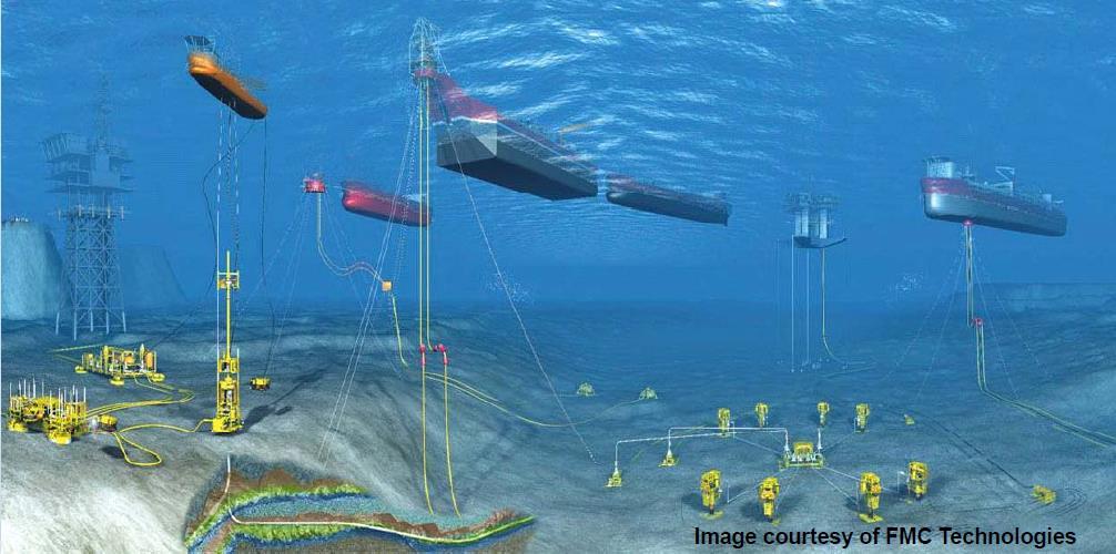
5 Complete FPSO/Manifold Interface
6

 : 28 API o black oil (gas gravity 0.")
7 Favorable condition for hydrate formation P, T profile in offshore flowlines : 8.27 inch ID, 27.6 mile insulated flowline (overall U-value of 3.6 Btu/hr ft 2 o F) : 28 API o black oil (gas gravity 0.83, GOR 200 scf/bbl)

8 Hydrate formation mechanism
 Hydrate nucleation and growth 3) Adhesion and aggregation 4) Deposition 5) Jamming or plugging - Hydrate")

9 Hydrate formation in normal operation - Hydrate formation in gas condensate system 1) Emulsification of oil into water 2) Hydrate nucleation and growth 3) Adhesion and aggregation 4) Deposition 5) Jamming or plugging - Hydrate formation in gas system 1) Hydrate coating on wall 2) Annulus growth of coating 3) Sloughing 4) Plugging Coating of hydrate on pipe wall is resulted from no emulsification and not enough interfacial tension Pipe material can make difference

10 Hydrate formation process - Hydrate do not act like hard spheres - Hydrate particles appear to aggregate (concentrated emulsion)
11 Proposed hydrate deposition for annular flow
12 Proposed hydrate deposition for wavy flow
13 Proposed hydrate deposition for stratified flow
14 Pipeline pressure drops due to hydrate
15 Early warning signs of hydrates Inspection of pigging returns for slush Changes in separator rates and compositions - Decrease in water flow - Decrease in H 2 S gas content Pressure drop increases (spikes) Acoustic signals (pinging along pipe)
16 How are hydrate plugs located? Locate center of plug - Close valve at wellhead - Depressurize platform end of line - Ratio rise in downstream vs. upstream P Locate downstream plug end - Pump gas into line from platform - Monitor P with time to calculate volume - Pipe length before plug = volume / area
17 How do they dissociate?

18 Pictures of dissociating hydrate plugs
19 Hydrate dissociation with ice and water present
20 Plug dissociation guideline Always dissociated: but require patience - Days or weeks required - Hourly changes ineffectual Cannot blow plug out of line - Causes more hydrate to form Depressurize lines as rapidly as safety allows - From both ends of plug - Ice formation helps transmit heat to plug
21 Dissociation guidelines (cont d) Depressure from one side slowly & carefully Difficult to locate plug & determine length Heating not recommended for plug Coiled tubing primary mechanical removal Liquid head can prevent dissociation Inject inhibitors before any shutdown Remove residual water after dissociation
22 Hydrate formation in Werner Bolley gas line sloughing plugging : Hydrate formation by coating and sloughing : Pressure spikes by onset of hydrate and partial plug at middle : Pressure surge by complete plug at final
23 Industry Practice: Rules of thumb (Natural Gas Hydrates in Flow Assurance, 2011, Dendy Sloan) If there is no water, then hydrate will not form For gas systems - Most likely to form hydrates during normal and startup operating scenarios - Most likely to form hydrates in the subsea system in areas where water collect and/or areas where flow direction is changed. - Most likely to form hydrates in the well across the choke For oil systems - Most likely to form hydrates during startup operating scenarios - Most likely to form hydrates in the subsea system in areas where gas and water have broken out of solution during startup operating scenarios
24 Hydrate mitigation Insulation - Pipe-in-pipe - Wet Insulation Active heating systems - Hot Water - Electric (DEH) Subsea Chemicals Injection - Methanol, MEG - LDHI Flowline Pressure Reduction Water removal (especially for Gas Export Pipeline)
25 Thermodynamic Hydrate Inhibitors (THIs) Methanol : Low cost : Low viscosity : No fouling : More toxic : Too little can be worse than none at low levels : Inefficient to recover : Reduce hydrocarbon sales value : High loss to gas phase MEG : Less toxic : Under-treating not as bad : Efficient to recover : Does not affect hydrocarbon value : Loss to gas phase negligible : High viscosity : Salts precipitation : Fouling by salt deposition
26 Application factors for THI Injection hardware Delivery & storage - large volumes Loss to hydrocarbon phase Salt precipitation Compatibility (materials & chemical) In-situ vs average water production rate Environmental, health & safety Regeneration
27 Estimation of Hydrate Formation/Inhibition (Accurate to ± 25%) 1. A pipeline pressure/temperature flow simulation should be done to determine the conditions between the wellhead and the pipeline discharge. (Pipesim, Olga, Leda, etc) 2. Hydrate formation conditions should be calculated, and pressures and temperatures of vapor and aqueous liquid inhibited by various amounts of THI should be considered. (Hammerschmidt eq., PVTSim, Multiflash, etc) 3. Calculate the amount of inhibitor injected into pipelines based on the amount of free-water phase
28 Hammerschmidt equation (1934) Hammerschmidt proposed the first empirical equation to find the required concentration of an inhibitor X, in an aqueous solution, for lowering the hydrate formation temperature by a given amount,( o F): T = ( 2335 MW X 1 X ) Where T temperature lowering, MW methanol molecular weight, X wt% methanol in aqueous phase. (For MEG, use 2000 instead of 2335) Extended equation for methanol (more accurate than the Hammerschmidt equation) T = ln(1 N) Where N mole fraction of methanol The accuracy the Hammerschmidt eq is surprisingly good; tested against 75 data points, the average error in T was 5%.
29 Cubic Equation of State (1980 ) Thermodynamic equilibrium Gas Gas Liquid HC Aqueous fugacity T Liquid HC fugacity Hydrate Aqueous f Gas = f LiqHC = f Aq f Gas = f LiqHC = f Aq = f Hyd
30 Fugacities in hydrate equilibrium Fluid Phases : Gas, Liquid, Aqueous : Fugacities from EoS (SRK, PR, etc) Hydrate Phases : Langmuir adsorption model : f hyd = f(langmuir Constants, Filling degree)
31 Effect of adding inhibitor Gas INH HC HC H 2 O Liquid HC HC HC HC HC HC HC H 2 O INH Aqueous H 2 OINH INH H 2 O INH HC HC Cluster formation by hydrogen bonding : lowering fugacity coefficient of water in aqueous phase
32 Pressure (bara) Required MEG concentration 350 Inhibition Point Hydrate Stability Zone Hydrate Free Zone Temperature ( C) 0 wt% MEG 10 wt% MEG 20 wt% MEG 30 wt% MEG 40 wt% MEG 50 wt% MEG 49 wt% MEG 48 wt% MEG 47 wt% MEG 48.5 wt% MEG Inhibition Point

33 Amount of free water Using water-content chart : Calculate for both inlet and outlet gas from the pipeline : Subtract the water content of the outlet from the inlet to determine the free-water phase condensed per mmscf Using equation of state : Calculate via super-saturation of dry gas under reservoir condition
34 Amount of inhibitor lost to the gas and HC phase MEG loss to vapor is negligible MeOH - At 39 o F, P > 1000 psi, MeOH lost to vapor phase is 1 lbm MeOH/mmscf for every wt% MeOH in the free-water phase (i.e. 27 wt% MeOH indicates 27 lbm MeOH/mmscf lost to vapor) - When the MeOH vapor loss can be substantially higher, ex) low water amount, it is recommended to use Kv for MeOH (=Yv/Xeq) Kv = exp ( (1/T( o R))) - MeOH loss to liquid HC (correlation for CH 4, C 3 H 8, n-heptane) Kv = exp ( (1/T( o R))) The total amount of MeOH injected to pipeline is therefore MeOH in aqueous phase + MeOH in gas + MeOH in condensate
35 Physical properties of MEG Pure MEG is given for reference only. Lean MEG or MEG90 (a mixture of 90 wt% MEG and 10 wt% water) is the fluid used for hydrate inhibition. MEG density at 10.0 o C Component Density Pure MEG kg/m 3 MEG kg/m 3 MEG90 will be transported at high pressure in the MEG distribution system, umbilicals and flowlines. It is important to know the physical properties of Lean MEG at elevated pressures and temperatures.
36