5555ter supply the Eugene Mill Race is a costly task that may have alternatives not explored by its
|
|
|
- Cameron Little
- 5 years ago
- Views:
Transcription
1 Scdr ter supply the Eugene Mill Race is a costly task that may have alternatives not explored by its proprietor. The electrical pumping of water into the no longer used Mill Race is costing the University of Oregon more than $30,000 annually. The University took on the operation and expense of the pump and used the Mio Race water to cool the discharge from the campus heating system. Now the use of more sustainable technologies has brought to question if the expense of pumping water in the waterway is justifiable as its current only use is a historical one. In this essay I will propose two options that could be considered that can bring the Eugene Mill Race water in a more sustainable and I will discuss other ways that water can be delivered to the Mill Race without the cost of the current electrical pump. Then I will propose and design that can help connect Springfield, Glenwood and Eugene for generations to come.

Pipe supply water source (2) Body of pump (3)Waste valve and flap (4) Check valve (5)Air chamber (6) Output pipe line basic design pipes gravity fed water in the intake")
2 An old technology can be used that can bring water up the 7 foot vertical distance from the Willamette River up to the mouth of the Mill Race without using electricity nor any other power source other than the river. Hydraulic Ram Pumps are complete automatic devices that use the kinetic energy of the river to pump water up hill. The design of the ram pump is simple and inexpensive to make. Figure 2. Ram pump start of cycle The (1)Pipe supply water source (2) Body of pump (3)Waste valve and flap (4) Check valve (5)Air chamber (6) Output pipe line basic design pipes gravity fed water in the intake body of the pump. The body has two exits. One through a waste flap valve that closes when the water build up cause s friction to push it up shut (see figure 1). When the flap closes the water Figure 1 Ram Pump in mid cycle pressure opens the other exit that is a check valve allowing the water to fill an air tight chamber (see figure 2). As the chamber fills with water the air in the chamber compresses. When the water pressure and air pressure are equal the pressure switch valve no longer is pushed open by water flow and shuts. At this point two things happen. The friction on the check valve is removed and the flap opens letting out water and causing flow to start in the body again. With the switch pressure valve closed the compressed air pushes the water in the chamber out the output pipe (see figure 3). The flow through

3 the body builds up and closes the check flap and the process repeats continuously cycling up to 100 times a minute. The output pipe must be half the diameter of the intake pipe. The cycles happen fast enough that a continuous flow of water is pumped up hill. In most models the amount of water moved uphill is 30% of the intake with the remaining water expelled as waste water out the check valve, however I have seen models claiming 75% efficiency according to Home Power Magazine (HPM 2017). Formulas used: I used the Hazel-Williams formula to calculate the flow rate each pump would produce with the above design. Q= 1440 [ES/(L/F)] Q= pumping rate in gallons per day (g/d) E= efficiency of hydraulic ram pump (using 0.6) Figure 3 Ram Pump end and restart of cycle S= source flow rate through the drive pipe in gallons per minute (g/m) L= vertical elevation lift from pump to output in feet per second (f/s) F= vertical fall from the source through the drive pipe feet per second (f/s) To calculate the velocity of the water entering the body of the pumps I used the Manning equation. V= (1.49/n) [(D/4) (2/3)] (S0.5) V= velocity of the water n- The roughness coefficient of the pipe D= pipe diameter S= slope of the pipe
4 According to the roughness coefficient: of concrete or cast iron is 100, for steel 120, cement 140, copper, plastics 150 for circular pipes. The formula is: D=(S x F x E)/L Where: D = Amount delivered in liters per 24 hours. S = Quantity of water supplied in liters per minute. F = the fall or height of the source above the ram in meters. E = the efficiency of the ram (for commercial models use 0.66, for home built use 0.33 unless otherwise indicated). L = the lift height of the point of use above the ram in meters. Above shows a possible set up for the ram pump. Using a galvanized pipe with a 15 inch diameter 418 feet long extended up river to reach a vertical head of 7 feet. This amount of head is able to pump water up to a maximum of 49 vertical feet above the ram pump. My survey of the area found that the highest point between the Mill Race and the suggested location of the pump was 9 feet in elevation. Horizontal distance does not change the output of the pump.


5 Following the above path to feed the ram pump with intake pipe diameter of 15 inches the calculations used produced the ability of the pump to produce gallons/min into the Mill Race using no other energy but that of the gravity flow in the head pipe. More than one pump can be installed to reach desired flow rate. Another option is to reconnect the river so that gravity instead of pumps feed water to the Mill Race. Although flooding and the new I-5 bridge construction has left little hope in restoring the original head water, there is another way. After spending many hours wondering through Glenwood taking GPS readings and finding elevation levels I have found a system that with some work and collaboration with the Cities of Eugene and Springfield the University can solve the Mill Race dilemma for good. The plan would be to connect the River via pipeline to a slough that runs along the outskirts of Glenwood being used mainly as storm water drainage. Then connecting the slough to the mouth of the Eugene Mill Race. This would create a canoe run running 2.3 miles long. Starting and the train trestle crossing the Willamette River south of the Springfield Bridge in Glenwood an intake pipe similar to the one that the Figure 5 Intake for Alton Baker Park Cano Canal city of Eugene uses for supplying water to the canoe canal at 4 Section 1

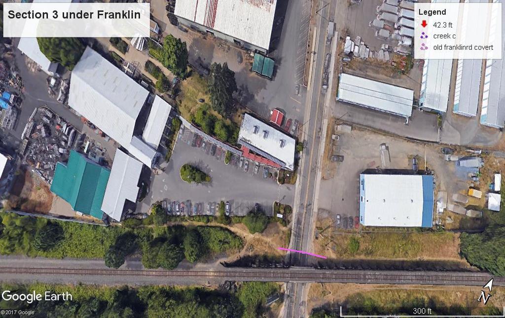
6 Alton Baker Park (see figure 4). In order to connect the intake to the slough a pipe line must be made through a landscape with varied elevations. After calibrating a GPS location reader I walked along many possible paths taking longitude and latitude readings at the same altitude as I progressed and later used those coordinates to precisely gain elevation points using Google Earth Pro. With the software I then constructed a series of sections in which each section having similar terrain and elevations. Depending on the average elevations in each section, I calculated the depth of the pipe that would be needed for gravity to feed water through it from the intake. Each section would have to be dug up and the pipe buried at the following locations. Creating a tunnel would allow access to the underground pipe and would be the ideal way, but building manholes every 50 yards with flush out valves could help keep maximum flow and the pipeline clear of debris. At the intake the water elevation is at 433. Section one would have to be put in the ground at an average depth of 14 for a distance of 418. Starting at coordinates 44 degrees north and -123 degrees west and ending at 44 degrees north and -123 degrees west (see data sheet for the remaining sections coordinates). Next, section 2 would run 361 at an average depth on 17. Which brings the pipe line to old Franklin Blvd. The pipe would need to extend 96 long and 16 deep under the road. Section four would have an average depth of 12 traveling 570. The longest section 5, must be 1,147 long averaging 8 deep. That would bring
7 the path to 19 th street. A depth of 18 must be made for 360 under 19 th street for section 6. Then section 7 would require the pipe to lay 450 feet long, 12 feet under the surface. At the end of section 7 the path intersects the slough, section 8 can go two different ways. At this point the bottom of the gully is at the exact elevation as the intake on the river. One option is to continue the pipe line along the railroad tracks digging 20 feet deep for another 577 feet and then a 1,100 feet 6 foot deep path to connect to the slough at its lowest point which is the same elevation at the start of the Mill Race, 428 feet. The other option is to end the pipe line at the end of section 7. As you can see in figure 6 there is some room to put a small parking lot. With Figure 6 some development the new Beginning to the open Eugene Mill Race could start at this point. For the canoe canal/mill race to continue above ground in section 9 a bridge would have to be built on Henderson to span the waterway. Currently the slough flows through a covert under the street. Once on the other side of Henderson Road the pond starts at the 428 foot elevation that makes this route so appealing. Section 10 would consist of another bridge constructed to replace the covert going under Glenwood Dr. The challenge that is left after Glenwood Dr. in this 2,611 foot long, 15 to 20 foot wide, already filled water way stretching to the I-5 Willamette Bridge would be getting rid of non-native species a restoring native fora and fauna to the area.
8 For the last section, anew canal would have to be made from the I5 bridge to the Mill Race, connecting the two waterways and thus creating a 2.3 mile sustainable canal (see figure 7) Figure 7 If this plan is to be realized, an effort should be made to study the existing environment and ecology to assess the impact on the wildlife that currently are in the area. Timing could not be any better for a project like this. With The annexation of Glenwood, the Springfield City Council has mandated that plans be made to redevelop the urban area to include restoration efforts for riparian areas, including wet lands, that promote citizen walking and that facilitate a connection between Springfield and Eugene. It s not hard to imagine a collaboration of the city of Springfield, the city of Eugene, The University of Oregon, Willamalane, the State of Oregon Conservation Strategy, and local
9 Conversation/Restoration organization. For the University any investment that leads to discontinue the electrical pump now supplying the water to the race would eventually pay for itself. Data collected: latitude all at 44 degrees and 02' longitude all at -123 degrees elevation "" N 1'37.104"W 428 ft " N 1'37.89"W 442 ft "N 1;57.126"W 447ft " N 2'.798"W 438ft 19,902"N 2'17.066"W 428ft "N 2'35.190"W 428 ft "N 3'23.520"W 428 ft "N 3'22.008"W 428 ft "N 3'20.694"W 428 ft Paths of sections
10

11

12


13


14


15


16
17