Hydraulic Machines, K. Subramanya
|
|
|
- Bernadette Armstrong
- 5 years ago
- Views:
Transcription
1 Hydraulic Machines power point presentation Slides has been adapted from Hydraulic Machines, K. Subramanya Prepared by Dr. Assim Al-Daraje 1
2 Chapter (1 Part 1) Prepared by Dr. Assim Al-Daraje INTRODUCTION 2
3 Hydraulic machinery Turbine is a device that extracts energy from a fluid (converts the energy held by the fluid to mechanical energy) Pumps are devices that add energy to the fluid (e.g. pumps, fans, blowers and compressors). 3
4 INTRODUCTION Fluid-flow machines are very broadly classified as turbo-machines and positive displacement machines. A turbo-machine is a device that adds energy to a fluid or extracts energy from the fluid by virtue of a rotating system of blades. These machines require a rotating element called rotor and relative motion between the fluid and the rotor. 4
5 If the machine adds energy it is called a pump; if it extracts energy it is called a turbine. The fluid to be pumped can be in incompressible mode throughout its passage in the machine or compressibility effects may come in to picture at different phases of its interaction in the machine. If the fluid is water, the pump device is labeled as water pump. 5
6 Turbines J.V. Poncelet first introduced the idea of the development of mechanical energy through hydraulic energy Modern hydraulic turbines have been developed by L.A. Pelton (impulse), G. Coriolis and J.B. Francis (reaction) and V Kaplan (propeller) 6

7 A-Pelton Wheel, B-Francis, Turbine, C-Kaplan Turbine 7
")
8 Pelton (impulse) 8
9 9
10 Kaplan (propeller) 10
11 11
12 Turbines Hydro electric power is the most remarkable development pertaining to the exploitation of water resources throughout the world Hydroelectric power is developed by hydraulic turbines which are hydraulic machines. Turbines convert hydraulic energy or hydropotential into mechanical energy. Mechanical energy developed by turbines is used to run electric generators coupled to the shaft of turbines Hydro electric power is the most cheapest source of power generation. 12
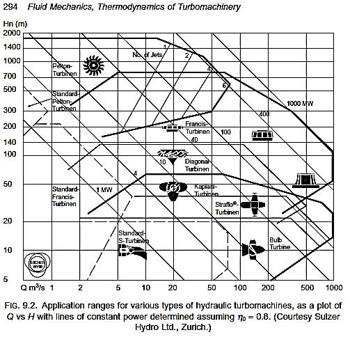
13 Classification of turbines Based on head and quantity of water According to head and quantity of water available, the turbines can be classified into a) High head turbines b) Medium head turbines c) Low head turbines a) High head turbines High head turbines are the turbines which work under heads more than 250m. The quantity of water needed in case of high head turbines is usually small. The Pelton turbines are the usual choice for high heads. 13
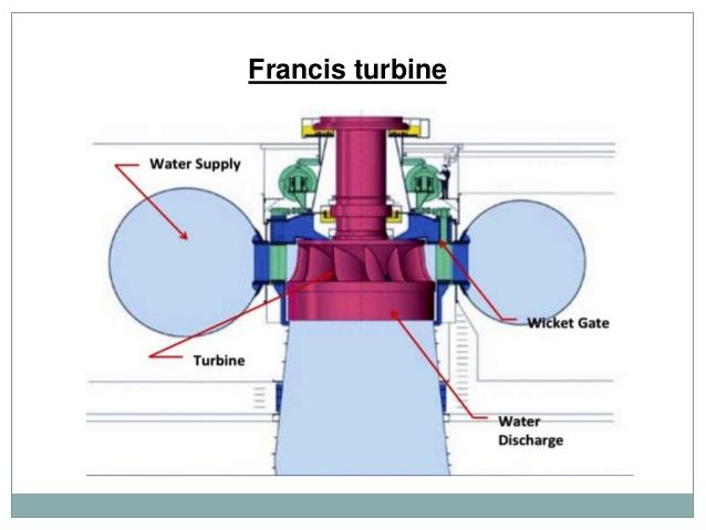
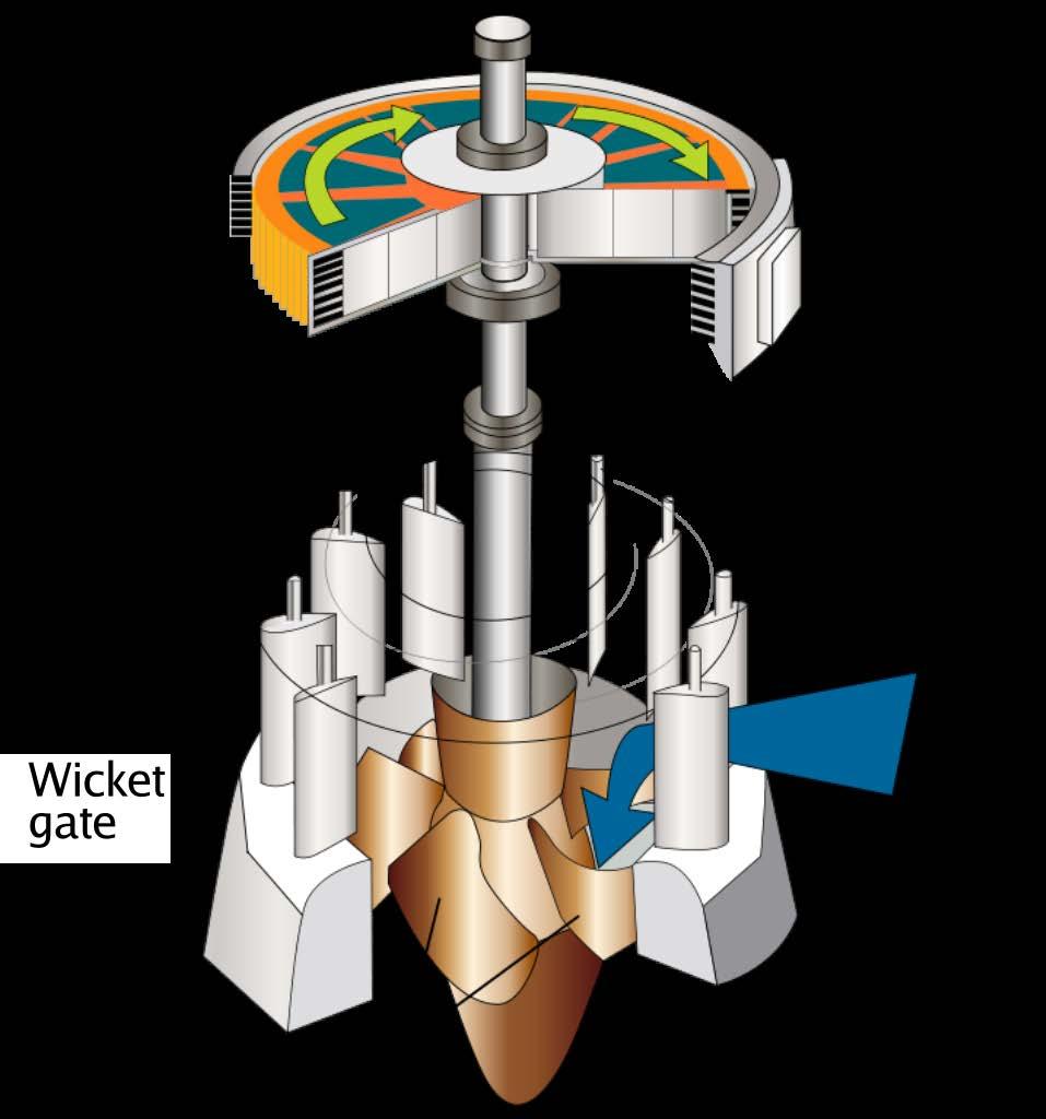
14 b) Medium head turbines The turbines that work under a head of 45m to 250m are called medium head turbines. It requires medium flow of water. Francis turbines are used for medium heads. c) Low head turbines Turbines which work under a head of less than 45m are called low head turbines. Owing to low head, large quantity of water is required. Kaplan turbines are used for low heads. 14
15 Classification of turbines: Based on hydraulic action of water According to hydraulic action of water, turbines can be classified into a) Impulse turbines b) Reaction turbines a) Impulse turbines If the runner of a turbine rotates by the impact or impulse action of water, it is an impulse turbine. b) Reaction turbines These turbines work due to reaction of the pressure difference between the inlet and the outlet of the runner. 15
16 Classification of turbines Based on specific speed of turbines Specific speed of a turbine is defined as the speed of a geometrically similar turbine which produces a unit power when working under a unit head. The specific speed of Pelton turbine ranges between 8-30, Francis turbines have specific speed between , Specific speed of Kaplan lies between Based on disposition of shaft of runner Usually, Pelton turbines are setup with horizontal shafts, where as other types have vertical shafts. 16
17 pumps For compressible fluids, the pump devices have nomenclatures such as fans, blowers and compressors. In positive displacement pumps, the fluid mass is physically displaced from one position to another owing to mechanical action of a boundary, for example a piston. There is a flow of fluid to fill the void created by this displacement and by repeated action, a continuous flow system is developed. A reciprocating pump is a typical example of a positive displacement pump. 17
18 Centrifugal Pumps A machine for moving fluid by accelerating the fluid RADIALLY outward. From the Center of a Circle RADIAL DIRECTION To the Outside of a Circle 18
19 Centrifugal Pumps This machine consists of an IMPELLER rotating within a case (diffuser) Liquid directed into the center of the rotating impeller is picked up by the impeller s vanes and accelerated to a higher velocity by the rotation of the impeller and discharged by centrifugal force into the case (diffuser). IMPELLER 19
20 Centrifugal Impellers Impeller Vanes Eye of the Impeller Water Entrance Diameter of the Impeller Thickness of the impeller Thicker the Impeller- More Water Larger the DIAMETER - More Pressure Increase the Speed - More Water and Pressure 20
21 Two Impellers in Series Direction of Flow Twice the pressure Same amount of water 21
22 Multiple Impellers in Series Direction of Flow Direction of Flow Placing impellers in series increases the amount of head produced The head produced = No. of impellers x head of one impeller 22
23 Heads, Losses and Efficiencies of Heads Hydraulic Turbines These are defined as below: (a) Gross Head: Gross or total head is the difference between the head race level and the tail race level when there is no flow. (b) Net Head: Net head or the effective head is the head available at the turbine inlet. This is less than the gross head, by an amount, equal to the friction losses occurring in the flow passage, from the reservoir to the turbine inlet. 23
24 Heads, Losses and Efficiencies of Hydraulic Turbines (d) Leakage losses: In case of impulse turbines, whole of the water may not be striking the buckets and therefore some of the water power may go waste. In a reaction turbine, some of the water may be passing through the clearance between the casing and the runner without striking the blades and thus not doing any work. These losses are called leakage losses. 24
25 (e) Mechanical losses: The power produced by the runner is not available as useful work of the shaft because some power may be lost in bearing friction as mechanical losses. f) Generator losses: Due to generator loss, power produced by the generator is still lesser than the power obtained at the shaft output. Efficiencies Various types of efficiencies are defined as under: (a) Hydraulic efficiency: It is the ratio of the power developed by the runner to the actual power supplied by water to the runner. It takes into account the hydraulic losses occurring in the turbine 25
26 Efficiencies of Turbines Attached figure is a definition sketch giving a schematic layout of a reaction turbine setup together with definition of various heads. Section 1 marks the entrance to the turbine. V e is the velocity at the exit of the draft tube. The velocity head V e 2, the energy head not utilized by the 2g turbine. For the turbine, the gross head H o is the difference between the upstream reservoir water level and the water level in the tailrace channel on the downstream. lf H L the head loss in the penstock (water conductor system), the head 26

27 available at entrance to the turbine minus the unutilized energy at the exit of the draft tube is called net head. The net head for a reaction turbine is 27
28 28
29 Heads, Losses and Efficiencies of Hydraulic Turbines η h = Runner output / Actual power supplied to runner = Runner output / (ρqgh) Where, Q = Quantity of water actually striking the runner blades H = Net head available at the turbine inlet 29
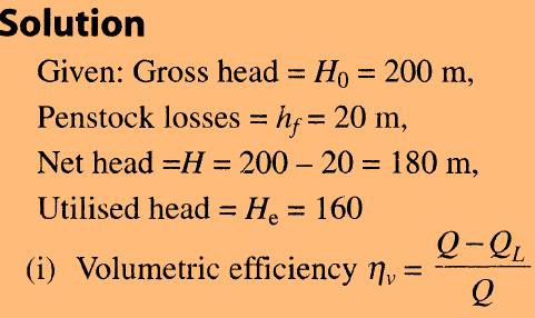
30 Heads, Losses and Efficiencies of Hydraulic Turbines Efficiencies (b) Volumetric efficiency: It is the ratio of the actual quantity of water striking the runner blades to the quantity supplied to the turbine. It takes into account the volumetric losses. Let Q = Quantity of water leaking or not striking the runner blades η v = Q / (Q+ Q) (c) Mechanical efficiency: The ratio of the shaft output to the runner output is called the mechanical efficiency and it accounts for the mechanical losses. η m = Shaft output / Runner output 30
31 Heads, Losses and Efficiencies of Hydraulic Turbines Efficiencies (d) Overall efficiency: Ratio of shaft output to the net power available at the turbine inlet gives overall efficiency of the turbine η m = Shaft output / Net power available η o Shaft. output = ρ ( Q + Q) gh Thus all the three types of losses, mechanical, hydraulic and volumetric have been taken into account. η o = Shaft. output Runner. output Runner. output ρqgh Q ( Q + Q) η = η η η o m h v 31
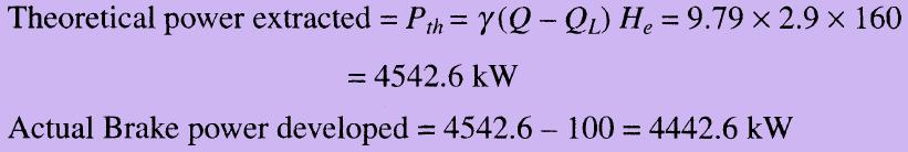
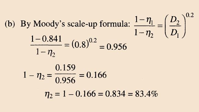
32 CH1 PART 1 Example 1:In a hydroelectric project, the upstream reservoir water level is 200 m above the tailrace water level of the power plant. When a discharge of 3.0 m3/s is supplied to the turbine, the frictional losses in the penstock are 20 m and the head utilized in the turbine is 160 m. The leakage loss is estimated at 0.1 m3/s and the mechanical losses can be taken as 100 kw. (a) Calculate the (i) volumetric efficiency, (ii) hydraulic efficiency (iii) mechanical efficiency, and (iv) overall efficiency of the system. (b) If a homologous turbine having a runner of diameter ratio.0.8 were tested under similar conditions, what would be its overall efficiency?
33
34
35