STATUS OF THE DEEP TUNNEL PROJECT OF GREATER CHICAGO
|
|
|
- Morgan Davidson
- 5 years ago
- Views:
Transcription

1 250 STATUS OF THE DEEP TUNNEL PROJECT OF GREATER CHICAGO by W. J. Bauer Bauer Engineering, Inc. Chicago, Illin o is Banquet Speaker - Thursday Evening - April 17 Construction Work Although no comprehensive plan for a tunnel system has as yet been adopted for the Chicago metropolitan area, three tunnels are currently under construction in the hard rock under the city. (See Fig. 1) One of these is (a) the Lawrence Avenue project of the City of Chicago; the other two are projects of the Metropolitan Sanitary D istrict of Greater Chicago, (b) one along 47th Street in the vicinity of LaGrange and Brookfield, and (c) the other along Crawford Avenue north of the Cal-Sag channel. All of them are being constructed by "moles". Lawrence Avenue tunnel will also involve the use of d rillin g and b la sting in some portions. This project has a completed length of about 7000 feet of mole-driven tunnel with a diameter of 13'8". The total in filtration into this tunnel in its present unlined and ungrouted condition is about 125 gallons per minute. The walls of the unlined tunnel were observed by the writer to have a roughness comparable to that of a large concrete pipe or concrete-lined tunnel. Very few rock fa lls occurred in the unlined mole-driven tunnel, and no rock bolts were required in this portion to hold up the rock in the roof. The other two tunnels are not far enough along at the present to comment on the progress to date. Unit costs based on contract amounts for construction of these tunnels including the cost of shafts for access and ventilation are compared in the following table: TABLE I COMPARISON OF TUNNEL COSTS Diameter Unit cost in $/ft/ft. dia. Tunnel Lined Unlined Lined Unlined Lawrence Avenue 12' CO CO i $30.00 $ th Street 15' 161-8" Crawford Avenue 15' 16'-8"


2 251 Figure 1 4- S «S c g / s trt /*^/ss Tunnels in rock under construction Tunnels in rock likely to be constructed during CALUMET AREA LEGEND { ~ Servtca area JL Treatment ptar. O Pumping statu P a rt A P a rt B... P o rt C

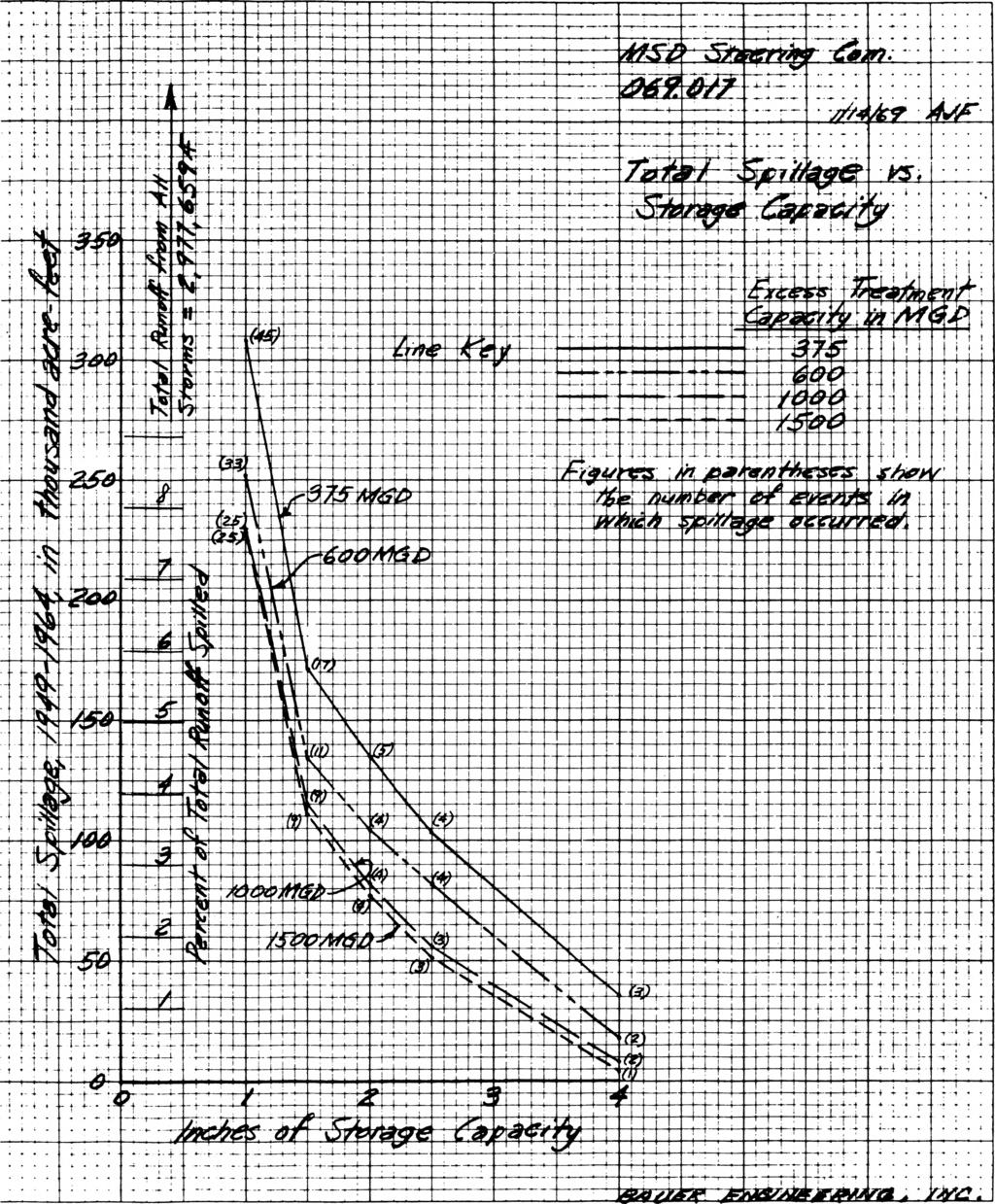
3 252 The cost in dollars per foot of length per foot of diameter for the lined tunnels is believed to be equal to or less than the cost of near-surface sewers of equal hydraulic capacity. It is therefore evident that the cost without lining is substantially less than would be required with conventional sewers. The lining is not required for the purpose of preventing pollution of the aquifer. It is also not required for structural or hydraulic purposes. Therefore it is likely, in the opinion of this writer, that the concrete lining will be omitted, and the corresponding cost saving achieved. Furthermore, not included in the foregoing cost comparison with conventional near-surface construction are the economic losses produced by the interruption of the use of the street during the period of construction of a near-surface sewer. Such interruptions are nearly eliminated with the choice of the hard rock tunnel. Because of the inherent capital cost savings and the avoidance of interruption of fa c ilitie s which can be achieved by using them, moledriven tunnels in rock are likely to be the choice for future large sewers in built-up portions of the Chicago area. This is true even if low-level outlets are not provided for such tunnels. S t ill further capital cost and operating cost savings could be achieved i f these tunnels were designed as parts of a deep tunnel plan such as that proproposed by Harza-Bauer for the Chicago area. Therefore, i t is reasonable to assume that an integrated and comprehensive plan w ill be developed by the agencies which have jurisd iction. Recent Studies Effect Upon Sewage Treatment Plant Capacity Recent studies have shown that storage of wastewater (both dryweather and storm flow) can be used to achieve a higher load factor on the treatment plants. In the Chicago area the dry-weather flow is about 0.01 cfs per acre or about 88 inches per year. The storm runoff is about 12 inches per year. Thus a treatment plant operated at ( )/88=1.14 times dry-weather flow and 100% load factor would treat the sum of dry-weather and storm flow. This would of course require an unlimited volume of storage. Conventional practice would use only the storage inherent in the collection and treatment system, and would provide, say, 2.0 times dry-weather flow in treatment capacity. Studies of 16 years of record of hourly rainfall in the Chicago area have indicated the relationship between storage volume treatment capacity, and the number and volume of runoff events not captured and treated. See Figure 2 attached. Discussion of the nature of this storage, and of the associated problems of solide handling and prevention of septic conditions are beyond the scope of this paper. It is very clear, however, that storage can be obtained for less cost than treatment plant capacity over the range of capacities studied which


4 253 Figure 2
 Water Reclamation.")
5 254 ranged from 2.0 down to 1.25 times dry-weather flow. (The curves labeled 375 MGD Excess Capacity in Figs. 1 and 2 are for 1.25 times dry-weather flow. The curves labeled 1500 MGD Excess Capacity in Figs. 1 and 2 are for 2.00 times dry-weather flow.) Water Reclamation. The use of storage and the associated high load factor on the treatment plants results in a water reclamation benefit as compared to treatment of the same volume of water at higher rates for shorter periods of time. The reason lies in the manner in which water may be withdrawn from Lake Michigan. Not only is the total volume of such withdrawal limited by Supreme Court Decree, but minimum flow rates must be maintained for purposes of dilution of effluent and for navigation. If captured storm water is treated at high rates and released over a short period to time, much of it would be of no use for purposes of dilution and navigation, as the rate.would be excessive. However, i f the same total volume can be treated and released at rates equal to or less than the requirements for dilution and navigation, it can be used to replace the corresponding discharge which would otherwise be withdrawn for Lake Michigan. At the present time about 500 cfs of the 3200 cfs allocation to Illin o is is not available for withdrawal from Lake Michigan because this much must be allowed for the storm runoff from watersheds formerly tributary to Lake Michigan. Capture and storage of this water would make part or all of this 500 cfs available for water supply. Comprehensive Planning. The Northeastern Illin o is Planning Commission (which operates in 6 counties having a population of about 6.5 million and an area of 3700 square miles) is currently developing a comprehensive plan for wastewater, stormwater, water supply, and solid waste disposal. In connection with this work, tunnel systems and alternatives to them are being considered from the point of view of how they w ill f it into the overall comprehensive plan. The following table indicates one perspective in which this consideration is being made: TABLE II COMPARISON OF COMBINED-SEWER AREA WITH REMAINDER OF 6-COUNTY AREA Combined Sewer Area Remainder of 6-County Area Approximate area in square miles Approximate population (1960) million 2.5 million Source of water supply Principally Principally Lake Michigan Groundwater

6 Cost estimates made in connection with comprehensive planning for the 300-square mile area indicate that the total cost for new treatment plants and new sewers without the tunnel system would be about equal to the cost of the alternative treatment plants and sewers with the tunnel system.. In other words, the savings in capital cost of new treatment plants and new sewers which would accrue from the construction of the tunnel system would be about equal to the cost of the tunnel system. Of course, the system with the tunnels would capture and treat nearly all of the overflows from the combined sewers, whereas the alternative conventional system of approximately the same cost would not. The foregoing comparison of costs of alternative systems is predicated upon the planning for tertiary and advanced treatment of waste water, including nutrient removal, filtra tio n, and chlorination. I f such treatment processes are to be constructed, i t becomes increasingly important to secure the high load factor on the plant which the storage provided by the tunnel system makes possible. Future Engineering Studies Vertical Shafts. There would be several hundred vertical shafts required for the complete tunnel system, ranging in hydraulic capacity from perhaps 40 cubic feet per second to as much as 1500 cubic feet per second. Tests may be underway in the near future to test a 12" shaft under a vertical drop of 170 to 300 feet to determine the requirements for operation with subatmospheric pressures so as to minimize the volume of a ir which is entrained in the water. Current designs for vertical shafts provide for a larger discharge rate for air than for water. I f the a ir can be largely excluded, the cost can be substa n tia lly reduced and w e ll-d rillin g techniques used in the construction of the shafts which w ill minimize disturbance to surrounding f a c ilit ie s during construction. Such shaft tests will also be used to evaluate the problems of trash, energy dissipation, and the possible change in settleable solids which may result from the passage of sewage through such a large drop. As shown in Figure 3, shaft heights w ill depend upon the depth of the tunnel; the piezometric head differential of the flow through the shaft w ill depend upon the location of the shaft along the route of the tunnel. Savings in Costs of Municipal Drainage. Although there have been made rough estimates, probably conservative, of the savings in costs of municipal drainage which would arise from the provision of the lowlevel outlet by the tunnel system, a series of studies of individual proposed drainage projects would be necessary to evaluate the savings on a municipality-by-m unicipality basis. In some instances, a proposed municipal drain would be completely eliminated by a tunnel following the same route. Figure 4 illu stra te s the reason for the savings in other instances.

7 Figure 3 PART B I- Conveyance along main drainage routes. 2. Interception of over flow points along rivers and channels. 3. Possible storage en route to reduce conveyance costs.

8 257 Possible surfoce reservoirs on local level for temporary storage of combined sewage in unusual circumstances PART C I. Conveyance through cities and villages to the conveyance tunnels of Part B. 2. Improvements in neighborhood drainage within cities and villages. Figure

9 258 The conveyance tunnel provides the outlet for the new local tunnel at a low elevation, affording much increased piezometric gradient for the new local tunnel, resulting in a smaller diameter. This saving would be added to the saving inherent in the use of the unlined mole-driven tunnel in the f ir s t place. By way of illustration, using $25 per foot per foot diameter for the alternative sewer and $17.50 for the unlined mole-driven tunnel, and assuming a ratio of piezometric gradients of 3:1, the diameter ratio would be 1.25:1, which would correspond to an 8' diameter instead of a 10', for example. The cost of the conventional 10' sewer would be 10 x $25 = $250 per foot. The cost of the 8' mole-driven unlined tunnel would be 8 x $17.50 = $140 per foot. The savings would be $90 per foot or 36%. This would not be an unusual case. Treatment Effect of Power Operation. Further studies are needed to evaluate the effect of the power generating operations on the quality of the water involved. No credit was taken for this effect in the evaluations of the tunnel concept so far, but it is recognized that several important inherent treatment effects may be present. Figure 5 illustrates the components of the system involved in an evaluation of the inherent treatment aspects. First of all, a large volume of power water is kept in the system at all times for purposes of power generation. This volume of water is alternately dropped through the turbines for the generation of power during periods of peak demand, and then pumped back up to the upper reservoir during periods of slack demand. It is exposed to the atmosphere in the upper reservoir, and may be conveniently aerated if desired in both the generating and pumping phases. Assuming that 1 mg/1 of oxygen were to be added during each pass through the pump-turbines and that the contemplated 7,000 million gallons of water are utilized each day in the power cycle, it would be possible to add about 100,000 pounds of oxygen per day to the water involved. This represents about 6% of the total present capacity of the Metropolitan Sanitary District. In addition, oxygen could be added by mechanical aeration in the upper reservoir. This p ossib ility could have an effect on the design of the integrated treatment system which would include the tunnel system and the present system of near-surface sewers and treatment plants. The volume of power water kept in the system is eaual to about 4 days of dry-weather flow of the entire system of the Metropolitan Sanitary District. Emergency bypasses could be handled relatively easily by simply passing them to the tunnel system, diluting them with the power water, and then returning them for treatment when the plant is ready to handle them. The value of this aspect of the tunnel system should also be evaluated by further study. Satellite Storage. The p ossib ility of using satellite storage along the route of the tunnel should be investigated. The value of such storage may be explained with the aid of Figure 6. With such storage the piezometric gradients applied to the tunnels may be made much

10 259 PART A I. Storage 2. Pumping - generating 3. Water reclamation Figure


11 260 Figure 6 ALTERNATIVE PART B Conveyance along main drainage routes 2. Interception of overflow points along rivers and channels 3. Possible storage en route to reduce conveyance costs

12 steeper, thus providing more conveyance capacity during the peak of the storm. Later, after the peak of the runoff rate has been passed, the entire system would drain out to the lower end for longer-term storage and subsequent treatment. Summary The current status of the deep-tunnel project for the Chicago metropolitan area may be summarized as follows: 1. Three tunnels in hard rock are under construction. Contract prices are less than conventional sewers of comparable hydraulic capacity, even without a low-level outlet for any of these tunnels. If a low-level outlet could be provided by an integrated system of tunnels and underground storage, the cost would be much lower s t i l l. 2. The provision of storage in the tunnel system makes possibl a much higher load factor on treatment fa c ilitie s. This has very important effects on the capacity of future additions to treatment f a c ilit ie s, a reduction in capacity of over 1000 MGD being possible by the use of storage. 3. The use of storage and the associated lower rate of treatment results in additional water supply being made available for withdrawal from Lake Michigan. 4. Studies made by the writer in connection with comprehensive planning for the Northeastern Illin o is area indicate that the total cost of waste-water handling without the tunnel system would be about the same as that of an integrated system in which no present conventional systems would be integrated into a tunnel system. The integrated system would provide much greater benefits. 5. Some of the future studies which should be made are those for the economical design of vertical shafts, for the design of future municipal drains to be connected to the tunnel system, for the evaluation of the inherent treatment capacity of the power-generation system, and for the benefit of sate llite or auxiliary storage along the tunnel routes.