NDE, Materials State Awareness, and Reliability Within the US Air Force
|
|
|
- Annice Briggs
- 5 years ago
- Views:
Transcription


1 NDE, Materials State Awareness, and Reliability Within the US Air Force 22 June 2016 Integrity Service Excellence Ryan Mooers Associate Materials Research Engineer Materials State Awareness Branch (RXCA) Structural Materials Division Materials and Manufacturing Directorate Air Force Research Laboratory 1
2 Disclaimer The views expressed in this presentation are those of the author and do not reflect the official policy or position of the United States Air Force, Department of Defense, or the United States Government 2

3 Outline Introduction Vision/ Motivation Who, What, How, and Where s Current Branch Efforts In-House Research Contracted Efforts POD and Reliability Connection with ASIP Doing a POD study Photo Courtesy of Dr. Eric Lindgren 3


4 USAF NDE Vision Digitally-enabled Reliable Nondestructive Quantitative Materials / Damage Characterization Regardless of Scale 4
5 Motivation / Objectives Improve NDE Capability / Reliability / Efficiency to Provide decision quality information to determine asset integrity (Safety FIRST!) Maintain user confidence in asset safety Minimize disassembly and related maintenance induced damage (save time and money) Minimize false calls Optimize materials design and production For Our Airmen 5

6 Initially for Quality Control Where We Came From 1919 Materials Section mission included make routine inspection tests for Procurement Section * Initial applications in radiography and magnetic particle inspections Evolved to include parts in use US Air Force established in 1947 Formalized NDT Section in 1952 NDE Branch stood up in 1974 Materials State Awareness Branch: Result of Reorganization in 2012 The next Air Force is going to be built around scientists around mechanically minded fellows. Gen H.H. Arnold Lt. H.H. Arnold, Military Aviator Number 1, 1911 General of the Air Force *Slipstream, 1919 McCook Field Newsletter 6


7 Where We Fit & What We Do Air Force Research Laboratory RXCA Research, Development, Transition RXSA Advanced Engineering, Rapid Response AF Life Cycle Management Center AF NDI Office Maintain NDI operational infrastructure NDI Executive Working Group AF Sustainment Center AFSC NDI Program Manager Complex NDI Managers Depot/Field/SPO Support 7

 Model-driven Quantitative Representation of Material/Damage State with Statistical Metrics")
8 How We Do It NDE Damage / Materials Characterization 3D Representation and Validation 1 Signal MAPOD Analysis 0.9 exp and Uncertainty Quantification POD crack length (in) Model-driven Quantitative Representation of Material/Damage State with Statistical Metrics Efficient and Effective ASIP/PSIP/MX Actions Augmented Materials Design, Processing, and Performance 8

9 Current Branch Activities Photo Courtesy of Dr. Eric Lindgren 9


10 In House Research Efforts Modeling and Simulation Eddy Current Ultrasound Complex/ Commercial Probes Angular/ Dimension Variation True Impedance Comparison Realistic microstructure Anisotropy Characterization based on received signal 10


11 In-House Research Efforts Composites Impact Damage Characterization 5 MHz Beam Model Area and depth shear longitudinal 10 MHz Beam Model shear longitudinal 11


12 In-House Research Material Characterization Micro texture Regions Produce false indication Potential to affect material properties Single Crystal Elastic Constant Measurement Crystal plasticity models Need accurate values CMC Degradation FTIR Inspection Chemical changes due to heating 70 μm SiC fiber BN SiO 2 Oxygen matrix 12


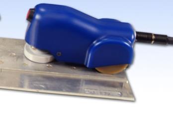
13 Contractual Efforts Structures Advanced Scanning Systems Increased accuracy, reliability, effectiveness Magneto Resistive Sensing Low frequency, multilayer inspection Remote Access NDE Hard to reach areas Minimize disassembly 13


 x V horiz 60 40 20 0 index,y (mils)")
 400 300 200 100 0-100 -200-300 -400 Simulation")

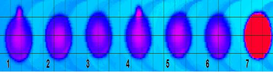
14 Sonic IR for Turbine Blades Whole field inspection Reduction operator time Reduced false call and hazardous waste Transitioning to Tinker AFB Next step: Disks Crack sizing in disk Model assisted inversion routine Contractual Efforts Propulsion Experimental. EC Probe y index,y (mils) T D40 20 x 10.matb scan,x (mils) x V horiz index,y (mils) V vert T D40 20 x 10.matb scan,x (mils) Simulation Model-assisted analysis of EC impedance plane index,y (mils) VIC-3D: 20x10x1.2 mil scan,x (mils) index,y (mils) VIC-3D: 20x10x1.2 mil scan,x (mils)
15 Longer Term Initiatives ASK (Advance Sustainment Knowledge) NDE Capture / exploit all NDE related data Assure inspections performed and performed as intended Increase effectiveness/efficiency of inspection processes Integrate into characterization efforts Damage State Awareness (DSA) Quantify size of damage detected Significant leveraging of modeling and simulation Data driven and Bayesian inversion routines Data Registration Register inspection data to specific location Use for potential inversion Tie to location and into Digital Thread/ Digital Twin 15

16 Life Management, POD and Reliability Photo Courtesy of Dr. Eric Lindgren 16


17 Link to USAF Integrity Programs Structures Aircraft Structural Integrity Program (ASIP) Established in 1958 after five destroyed B-47 aircraft in March April 1958* Four losses attributed to fatigue Uses probabilistic approach to establish aircraft service life capability: Safe-Life Loss of F-111 (Dec, 1969)* and F-5 (April, 1970)* far short of qualified Safe-Life Designs intolerant of manufacturing and/or service-induced defects Leads to Damage Tolerance Approach Tolerate defects for some inspection-free period of service usage Formally integrated into ASIP in 1975 *ASC-TR , Threats to Aircraft Structural Safety, Incl. a Compendium of Selected Structural Accidents/Incidents, March
 ENSIP MIL-STD 1783, published 1984 Becomes MIL-HDBK-1783 in 1997, now Rev B PSIP MIL-STD 3024, published 2008 Applicable to gas turbine engines")

18 Link to USAF Integrity Programs Propulsion Propulsion Structural Integrity Program (PSIP) Introduced in 1978 as Engine Structural Integrity Program (ENSIP) ENSIP MIL-STD 1783, published 1984 Becomes MIL-HDBK-1783 in 1997, now Rev B PSIP MIL-STD 3024, published 2008 Applicable to gas turbine engines Essentially a safe life approach but crack growth criteria also enforced Components retired with remaining serviceable life Damage Tolerance Methods to extend service life are being pursued P&W F-100* GE F-110** * ** 18
19 Overview of ASIP Aircraft Structural Integrity Program (ASIP) Governed by MIL-STD-1530C Establishes required safety metrics for structures Fracture mechanics enables predictive management of fatigue Periodic inspection before crack reaches critical size Composites are approaching DTA capability Predictive damage evolution is maturing towards realization Corrosion managed by time-based assessments Prediction of corrosion evolution not available Primary hurdle is predicting breakdown of coatings and/or inhibitors in primers/sealants USAF is meeting required safety metrics for structures, but at a high cost 19
20 NDE in ASIP: Representative DTA Risk Assessment Initial Crack Size Distribution Inspection Capability (POD) Repair Crack Size Distribution Probability of Failure between Inspections Max Stress per Flight Integration/ Calculation Single Flight Probability of Failure Crack Growth Curve Stress Intensity Factor Fracture Toughness Cumulative Expected Failures 20
21 NDE in ASIP: Representative DTA Risk Assessment Initial Crack Size Distribution Max Stress per Flight Crack Growth Curve Inspection Capability (POD) Stress Intensity Factor Integration/ Calculation Repair Crack Size Distribution NDE/SHM POD: a primary input into risk assessment Fracture Toughness Probability of Failure between Inspections Single Flight Probability of Failure Cumulative Expected Failures 21
22 DTA Crack Growth Crack Size, l Critical Length Initial Flaw Size Estimate I 1 I 2 Time to Critical Length Flight Hours 22
23 DTA Crack Growth Cont. Crack Size, l We didn t find anything We get to use new initial crack length based on NDE capability Flight Hours I 1 23
24 DTA Crack Growth Cont. Crack Size, l We didn t find anything How Do We get to use new Determine initial our crack length NDE Capability based on NDE capability Flight Hours I 1 24
25 Probability of Detection Probability that, for a crack of certain length: The signal will be at a detectable level during a given inspection scenario & The inspector will call out a flaw Sources of uncertainty: Probe characteristics Operator Calibration procedure Electrical noise in systems Crack features And many more 25
26 Major Parts to a POD Study Capture variability in parameter space Some are known to be unimportant others are too difficult to vary over Develop a test matrix to capture data from all variations Determine min and max values of parameters or guess at distributions (Full or Sparse) Document why other parameters weren t considered Gather Experimental Data Many inspection opportunities representative parts With and without flaws 26
27 Signal Strength, a (V) 0.35 Building a POD Curve a = β 0 + β 1 a + ε ε~n[0, σ 2 ] Flaw Size, a(mm) 27
28 Signal Strength, a (V) Flaw Size, a(mm) Building a POD Curve Flip the graph on its side Signal Flaw Strength, Size, a(mm) (V)
29 Flaw Size, a(mm) Building a POD Curve Set threshold value a th Fix value of a Identify region of response curve above threshold Fixed a value Integrate this area for all values of a Signal Strength, a (V) 29
30 POD Curve This is where we get the NDE limit Probability of Detection, POD(a) a 20 a 90 a 90/95 Which Point Input to DTA Curve or just a few points Largest flaw we will miss Flaw Size, a x
31 NDE in ASIP: Representative DTA Risk Assessment Initial Crack Size Distribution Inspection Capability (POD) Repair Crack Size Distribution Probability of Failure between Inspections Max Stress per Flight Integration/ Calculation Single Flight Probability of Failure Crack Growth Curve Stress Intensity Factor Fracture Toughness Cumulative Expected Failures 31

32 Thank you! Questions? Photo Courtesy of Dr. Eric Lindgren 32