Section 3: Management Practice Standards
|
|
|
- Sydney Small
- 5 years ago
- Views:
Transcription
1 Section 3: Management Practice Standards SECP Code NRCS Code CASQA Code SECP, NRCS, and CASQA Codes Current Irrigation Infrastructure Practices I Drip/microspray irrigation installed and used. I I I I Use of irrigation equipment (sprinklers, micro-sprinklers, emitters, etc.) to match soil infiltration rates as much as possible to prevent runoff. Recirculation systems are used to keep sediment and farm inputs on site. Water is recirculated to irrigated other fields. In-furrow dams are used to increase infiltration and settling out of sediment prior to entering the tail ditch. Storm water is captured using field borders to reduce runoff and supplement field irrigation. I EC-10 Use of flow dissipaters to minimize erosion at discharge point. I Shorter irrigation runs are used with checks to manage and capture flows. I-8 464, 466 Land grading has been done to increase irrigation efficiency and improve control of drainage. I-9 330, 331 Fields are planted on the contour to reduce runoff. I I , 362, 423 Crop rows are graded, directed and at a length that will optimize the use of rain and irrigation water. Berms are constructed at low ends of fields to capture runoff and trap sediment. I Vegetative filter strips and buffers are used to capture flows. I , 462 Subsurface pipelines are used to channel runoff water. I-14 I-15 I-16 SECP Code 350, 378, 554 NRCS Code M M-2 449, 595 M-3 635, 412 SE-3 SE-4, EC-9, SC-1, SE-10, EC-11 CASQA Code Hedgerows or trees are used to help stabilize soils and trap sediment movement. Sediment basins / holding ponds are used to settle out sediment and hydrophobic pesticides such as pyrethroids from irrigation and storm runoff. Other irrigation practices (attach additional sheets if necessary to list and describe practices): Current Irrigation Management Practices Use of irrigation scheduling methods and equipment to match irrigations to crop needs where possible. The time between pesticide applications and the next irrigation is lengthened as much as possible to mitigate runoff of pesticide residue. Vegetated ditches are used to remove sediment as well as water soluble pesticides, phosphate fertilizers and some forms of nitrogen.
2 SECP, NRCS, and CASQA Codes M Cover crops or native vegetation are used to reduce erosion. M-5 324, 610 M EC-5 Soil water penetration has been increased through the use of amendments, deep ripping and/or aeration. PAM (polyacrylamide) used in furrow and flood irrigated fields to help bind sediment and increase infiltration. M-7 345, 329 Minimum tillage incorporated to minimize erosion. M-8 EC-3, EC-7, EC-4, EC-6 Other irrigation management practices (attach additional sheets if necessary to list and describe practices): SECP Code NRCS Code CASQA Code Other Practices O TC-2 Grade access roads to reduce on-road erosion. O-2 578, 587 Control concentrated drainage on roads with culverts, rolling dips, etc. O-3 472, 560 Direct drainage off road to vegetated area, ditches, sediment basins, etc. O-4 342,560 O Protect roads in rainy season by seeding roads, rice straw, gravel, avoid use, etc. Check culverts in rainy season to ensure they are not plugged with debris. O Minimize erosion downstream of culverts by using energy dissipaters. O-7 Remove/avoid stream crossings wherever possible. O-8 580, 322 EC-12 Creek banks and stream banks have been stabilized. O-x 468 TC-1 Other practices *CASQA: California Storm Water Quality Association
3 Resource Index NRCS Conservation Practice Standards Irrigation System, Microirrigation (441) Irrigation Water Management (449) Irrigation System, Tailwater Recovery (447) Irrigation System, Surface and Subsurface (443) Stormwater Runoff Control (570) Structure for Water Control (587) Irrigation Land Leveling (464) Land Smoothing (466) Contour Farming (330) Contour Orchard and Other Perennial Crops (331) Row Arrangement (557) Diversion (362) Hillside Ditch (423) Sediment Basin (350) Filter Strip (393) Precision Land Forming (462) Subsurface Drain (606) Hedgegrow Planting (422) Drainage Water Management (554) Pond (378) Integrated Pest Management (595) Grassed Waterway (412) Vegetated Treatment Area (635) Cover Crop (340) Deep Tillage (324) Salinity and Sodic Soil Management (610)
4 Anionic Polyacrylamide (PAM) Application (450) Residue and Tillage Management No-Till/Stip Till/Direct Seed (329) Access Road (560) Stream Crossing (578) Access Control (472) Critical Area Planting (342) Amending Soil Properties with Gypsum Products (333) Streambank and Shoreline Protection (580) Lined Waterway or Outlet (468) CASQA Best Management Practices Velocity Dissipation Devices (EC-10) Sediment Trap (SE-3) Check Dams (SE-4) Earth Dikes and Drainage Swales (EC-9) Silt Fence (SC-1) Storm Drain Inlet Protection (SE-10) Slope Drains (EC-11) Soil Binders (EC-5) Geotextiles and Mats (EC-7) Hydraulic Mulch (EC-3) Hydroseeding (EC-4) Straw Mulch (EC-6) Stabilized Construction Roadway (TC-2) Stabilized Construction Entrance/Exit (TC-1)

5 Irrigation System, Microirrigation (441) Conservation Practice Standard Overview Irrigation System, Microirrigation (441) A microirrigation system, also known as drip or trickle irrigation, is used to make frequent application of small quantities of water on or below the soil surface, as drops, tiny streams or miniature spray through emitters, or applicators placed along a water delivery line. Practice Information Microirrigation systems are installed to efficiently and uniformly apply irrigation water and/or chemicals directly to the plant root zone and maintain soil moisture for optimum plant growth. Microirrigation is also used to provide irrigation water to establish desired vegetation such as windbreaks, living snow fences, riparian forest buffers, and wildlife plantings. Microirrigation is suited to virtually all agricultural crops, as well as residential and commercial landscape systems. It is also suited to steep slopes where other methods would cause excessive erosion, and areas where other application devices interfere with cultural operations. Local water test results should be obtained and used to determine irrigation suitability and plan for potential treatment needs. The movement of dissolved substances below the root zone may affect groundwater quality. As with all irrigation, there may be effects to downstream flows or aquifers, and the amount of water available for other water uses. Operation and maintenance of a microirrigation system involves periodic inspections and the prompt repair or replacement of clogged or damaged components. Additionally, the operator will need to determine and control the volume, frequency and application rate of irrigation water in a planned, efficient manner. Common Associated Practices Irrigation System, Microirrigation (441) is commonly applied with conservation practices such as Water Well (642), Irrigation Reservoir (436), Pumping Plant (533) Irrigation Water Conveyance, Pipeline (430), and Irrigation Water Management (449). For further information, contact your local NRCS field office. Natural Resources Conservation Service Helping People Help the Land USDA is an equal opportunity provider and employer. September
6 441-CPS-1 Natural Resources Conservation Service CONSERVATION PRACTICE STANDARD IRRIGATION SYSTEM, MICROIRRIGATION CODE 441 (Ac.) DEFINITION An irrigation system for frequent application of small quantities of water on or below the soil surface: as drops, tiny streams, or miniature spray through emitters or applicators placed along a water delivery line. PURPOSE This practice is applied to achieve the following purpose: Efficiently and uniformly apply irrigation water and maintain soil moisture for plant growth. Prevent contamination of ground and surface water by efficiently and uniformly applying chemicals. Establish desired vegetation (e.g., windbreaks). CONDITIONS WHERE PRACTICE APPLIES This practice applies on sites where soils and topography are suitable for irrigation of crops or other desirable vegetation and an adequate supply of suitable quality water is available for the intended purpose(s). Microirrigation is suited to virtually all agricultural crops, and residential and commercial landscape systems. Microirrigation is also suited to steep slopes where other methods would cause excessive erosion, and areas where other application devices interfere with cultural operations. Microirrigation is suited for use in providing irrigation water in limited amounts to establish desired vegetation such as windbreaks, living snow fences, riparian forest buffers, and wildlife plantings. This practice standard applies to systems that wet only a specific area (e.g., an individual plant or tree) and typically have design discharge rates less than 60 gal/hr at individual application discharge points. Use NRCS Conservation Practice Standard (CPS) Code 442, Sprinkler System, for systems that uniformly wet the entire field and typically have design discharge rates of 60 gal/hr or greater at individual application discharge points. CRITERIA General Criteria Applicable to All Purposes Design the system to uniformly apply water and chemicals without excessive water loss, erosion, reduction in water quality, or salt accumulation. Provide backflow prevention devices on all microirrigation systems equipped for chemical injection. Locate and install injectors (chemical, fertilizer, or pesticides) and other automatic operating equipment in Conservation practice standards are reviewed periodically and updated if needed. To obtain the current version of this standard, contact your Natural Resources Conservation Service State office or visit the Field Office Technical Guide. NRCS, NHCP September
7 accordance with manufacturer s recommendations and include integrated back flow prevention protection. 441-CPS-2 Include all system appurtenances necessary for proper operation. Size and position each appurtenance in accordance with sound engineering principles and site-specific features. Appurtenances may include but are not limited to totalizing flow measurement devices, water filtration, air vent valves, vacuum relief valves, pressure relief valve(s), water control valve(s), pressure gauges, pressure regulators, and pressure reducers. Water Quality. Test and assess the irrigation water supply for physical, chemical, and biological constituents commonly encountered in the area that may cause clogging of microirrigation system emitters. Use water test results to determine irrigation suitability and treatment requirements. Emitter Discharge Rate. Determine the design discharge rate of applicators based on manufacturer s data for expected operating conditions. Limit discharge rates to avoid creating runoff within the immediate application area. For bubbler irrigation, design a basin around the plant for water control, and confine applications to the basin area. Number and Spacing of Emitters. Provide adequate water distribution to the plant root zone and percent plant wetted area (Pw) with proper emitter selection and spacing of emitters along each lateral. Use procedures found in NRCS National Engineering Handbook (NEH), Part 623, Chapter 7, Microirrigation, to calculate Pw. Operating pressure. Select the design operating pressure in accordance with published manufacturer s recommendations. Account for pressure losses and gains through system components and field elevation effects. Do not exceed the manufacturer s recommendations for maximum pressure in any lateral or manifold during any phase of operation. Emitter manufacturing variability. Obtain and use the manufacturer s coefficient of variation (Cv) to assess acceptability of a particular product for a given application. Select products that have a Cv of less than 0.05 for point source emitters and less than 0.07 for line source emitters. Allowable pressure variations. Manifold and lateral lines. Design manifold and lateral lines operating at design pressure to provide uniform discharge to all applicators in an irrigation subunit or zone. The flows to all applicators in an irrigation subunit or zone will not have a total variation greater than 20 percent of the design discharge rate. Follow manufacturer recommendations concerning internal pressure during all phases of operation. Main and submain lines. Design mains and submain lines to supply water to all manifold and lateral lines at a flow rate and pressure not less than the minimum design requirements of each subunit. Provide adequate pressure to overcome all friction losses in the pipelines and appurtenances (valves, filters, etc.). Maintain flow velocities at no more than 5.0 ft/sec in all mains and submains during all phases of operation, or provide special consideration to flow conditions and take measures to adequately protect the pipe network against surge pressures. NRCS CPS Code 430, Irrigation Pipeline, applies to mains and submains but not to manifolds. Emission Uniformity (EU). Pipe sizes for mains, submains, and laterals shall maintain subunit (zone) emission uniformity (EU) within recommended limits as determined by procedures contained in NEH, NRCS, NHCP September
8 441-CPS-3 Part 623, Chapter 7, Microirrigation. System design EU must be 85 percent or higher where fertilizer, pesticides, or treatment chemicals are applied through the system. Filters. Provide a filtration system at the system inlet. Design the filters for a maximum head loss of 5 psi under clean conditions. Base the maximum design head loss across a filter before cleaning on manufacturer s recommendations. In the absence of manufacturer s data, maximum head loss across a filter before cleaning is 10 psi. Size the filtration system to prevent the passage of solids in sizes or quantities that might obstruct the emitter openings. Design the filtration system to remove solids based on the emitter manufacturer s recommendations. In the absence of manufacturer s data or recommendations, design filtration systems to remove solids equal to and larger than one-tenth the emitter opening diameter. Ensure filter back flush does not cause discharge of media material, excessive flush water, or unacceptable EU. Ensure design provides for disposal and utilization of filter back flush water. Back flush water should not cause erosion or chemical contamination. Air/Vacuum Relief Valves. Design and install air and vacuum relief valves at system manifolds and lateral summits. Design and locate all vacuum relief valves to prevent introduction of soil particles into the irrigation system due to vacuum. Install air/vacuum relief valves on both sides of all subunit or manifold water supply control valves. Pressure regulators. Use pressure regulators where topography and the type of applicator dictate their use. System flushing. Install appropriate fittings above ground at ends of all mains, submains, and lateral flush manifolds to facilitate flushing. An acceptable alternative to flush manifolds would be to install fittings at the end of individual laterals to provide flushing above ground or into a drainage ditch. Design and install the system to provide a minimum flow velocity of 1 ft/sec during flushing. Do not exceed flush velocities of 7 ft/sec in submains or manifolds located downstream from a control valve. Do not exceed the manufacturer s maximum recommended flushing pressure in laterals. Include a pressure gauge and/or Schrader valve tap at each flushing manifold outlet serving subsurface drip irrigation (SDI) systems. Make provisions for flush water discharged from flush valves. Locate flush valves such that flows are directed away livestock, electrical equipment, and other control valves or hook-ups. Ensure discharge of flush water is in a non-erosive manner Water Management Plan. Develop an Irrigation Water Management Plan meeting the requirements of NRCS CPS Code 449, Irrigation Water Management, for use with this practice. Additional Criteria Applicable to Efficiently and Uniformly Apply Irrigation Water System capacity. Design the system with sufficient capacity to meet water application requirements during critical crop growth periods. Include in the design capacity an allowance for reasonable water losses (evaporation, runoff, deep percolation, and system deterioration over time), and auxiliary water needs such as leaching, frost protection, and cooling. If water test results indicate a need include adequate water for leaching in the gross application volume calculation to maintain a steady state salt balance. Subsurface Drip Irrigation (SDI). Tubing depth and spacing are soil and crop dependent. Select the emitter line depth based on the auxiliary irrigation methods used for leaching, germination, and initial development. The maximum lateral line distance from the crop row is 24 inches for annual row crops. NRCS, NHCP September
9 441-CPS-4 Surface Microirrigation Systems (SI). Install surface drip lateral lines on the ground along the plant row(s). Provide 2 percent extra length to surface laterals to allow for expansion and contraction of the line. Pin or anchor above-ground drip lines to prevent dislodging or movement of the line away from the plants or pots. In lieu of pins, laterals may be buried (2 4 ) below the soil surface and under mulch or plastic row covers. When lateral emitter spacing or capacities vary with each row, design the laterals separately. Design and install main and submain lines to have safe velocities. Anchor mains, submains, manifolds, and laterals as needed to prevent undesired movement. NRCS CPS Code 430, Irrigation Pipeline, applies to mains and submains but not to manifolds. Additional Criteria Applicable to Preventing Contamination of Ground and Surface Water Chemigation and Chemical Water Treatment. System EU shall not be less than 85 percent where fertilizer or pesticides, or treatment chemicals are applied through the system. Backflow prevention devices shall be provided on all microirrigation systems equipped for chemical injection. Injectors (chemical, fertilizer, or pesticides) and other automatic operating equipment shall be located and installed in accordance with manufacturer s recommendations and include integrated back flow prevention protection. Chemigation shall be accomplished in the minimum length of time needed to deliver the chemicals and flush the pipelines. Application amounts shall be limited to minimum amount necessary, and rate shall not exceed maximum rate recommended by chemical label. Proper maintenance and water treatment shall be followed to prevent clogging based upon dripper and water quality characteristics. Irrigation water supply tests shall be used to plan for addressing or avoiding chemical reactions with injected chemicals to prevent precipitate or biological plugging. Additional Criteria Applicable to Establishing Desired Vegetation System capacity. Design the system with capacity to provide supplemental water at a rate that will ensure establishment and survival of planned vegetation. Net application volumes per plant are dependent on the species of tree or shrub and the age (e.g., first, second, and subsequent years). Determine the gross application volume per plant using field application efficiency consistent with the type of microirrigation system planned. Systems may utilize manual flush screen filters and manual flush valves or fittings at individual lateral ends. Filter screening criteria is in the section General Criteria for All Purposes. Place drip lateral lines installed on the ground surface along the plant row(s) in a serpentine pattern to allow for expansion and contraction of the line while keeping the emitter close to the tree or shrub. Pin or anchor above-ground laterals to prevent the line from being dislodged or moved away from the trees or shrubs. Design each lateral separately when lateral emitter spacing or capacities vary with each row. CONSIDERATIONS System operation should not exceed 22 hours per day or 6 days per week. NRCS, NHCP September
10 441-CPS-5 In the absence of local experience, use a field application efficiency (E) of 90 percent to estimate system capacity. In arid climates with subsurface systems, natural precipitation and stored soil water is often inadequate to provide crop germination. If the microirrigation system cannot germinate seeds or establish transplants, make special provisions for germination (i.e., portable sprinklers). Limit the depth of subsurface systems on annual crops to retain the ability of the system to germinate seeds, unless providing other provisions for this function. Consider potential rodent damage when selecting materials and deciding on above-, shallow-, or belowground system installation. Organic farmers may apply less soluble fertilizers through the microirrigation system. Take precautions against potential emitter clogging. Consider weather conditions before applying chemicals. Pest or nutrient management planning should address the timing and rate of chemical applications. Field shape and slope often dictate the most economical lateral direction. Laying laterals down slope can allow for longer lateral run lengths and lateral size reduction. The designer must ensure pressure stays in a reasonable range. Uneven topography may require use of pressure-compensating emitters. Economic assessments of alternative designs should include equipment and installation as well as operating costs. It is preferable to have an air/vacuum relief with continuous air release function on the mainline side of zone valves. During establishment of windbreaks, use longer, less frequent irrigations to encourage deeper root development that increases drought tolerance. Include secondary screen filters following the media filters or a rinse cycle valve to prevent release of contaminants following the backwashing process. Do not apply chemicals if rainfall is imminent unless system applies chemicals under plastic mulch. Use irrigation water supply tests and/or the jar test to help avoid reactions with injected chemicals and prevent precipitate or biological plugging. Place laterals upslope of crop rows when they are on the contour to assure even wetting patterns within the root zone. Installation and operation of microirrigation systems has the potential to save energy due to reduced seasonal irrigation application, and in some situations reduced operating pressures. PLANS AND SPECIFICATIONS Describe the requirements for properly installing the practice to achieve its intended purpose in the plans and specifications. Include in the plan: A plan map showing the location, key elevations, system layout documenting material, and sizes of all pipelines, control valves, air/vacuum valves, pressure regulating valves, wellhead components, and other appurtenances. System design pressure and flow rate. NRCS, NHCP September
11 Subunit location, dimensions, and layout. Emitter type, design operating pressure, and flow rate. Appurtenance location, type, size, and installation requirements. 441-CPS-6 Provide site specific construction specifications that describe in detail installation of the irrigation system and all associated components. Additional information regarding operation of the system will be included in the Irrigation Water Management Plan, Waste Utilization Plan and/or Nutrient Management Plan, as applicable for the practice purpose. OPERATION AND MAINTENANCE Operation and maintenance (O&M) items specific to vegetation establishment are included in NEH, Part 652, Chapter 6, (h), Windbreaks. Develop and review the site-specific O&M plan with the landowner/operator. Provide specific instructions in the O&M plan for operating and maintaining the system to ensure it functions properly, including reference to periodic inspections and the prompt repair or replacement of damaged components. At a minimum, include the following items in the O&M plan: Inspect flow meter, if applicable, and monitor water application. Clean or backflush filters, as needed. Flush lateral lines at least annually. Perform visual inspection of crop performance and emission device flows if visible and replace applicators, as necessary. Measure pressure often on installed gauges or at Schrader valves with a handheld gauge to ensure proper system operation. A pressure drop (or rise) may indicate a problem. Check pressure gauges to ensure proper operation. Repair or replace damaged gauges. Follow proper maintenance and water treatment to prevent clogging based upon dripper and water quality characteristics Inject chemicals as required to prevent precipitate buildup and algae growth. Check chemical injection equipment regularly to ensure it is operating properly. Check and assure proper operation of backflow protection devices. Make provisions for the complete removal of water from the pipeline by gravity or other means when: o Freezing temperatures are a hazard, o The pipe manufacturer requires draining, o Draining of the pipeline is otherwise specified. The water drained from pipelines shall not cause water quality, soil erosion, or safety problems upon release. REFERENCES USDA-NRCS, National Engineering Handbook, Part 623, Chapter 7, Trickle Irrigation. USDA-NRCS, National Engineering Handbook, Part 652, Irrigation Guide. NRCS, NHCP September
12 3-8

13 Irrigation Water Management (449) Conservation Practice Standard Overview Irrigation Water Management (449) Irrigation water management is the process of determining and controlling the volume, frequency, and application rate of irrigation water in a planned, efficient manner. Practice Information Irrigation water management is primarily used to manage soil moisture to promote plant growth. It can also be used to optimize use of available water supplies, minimize irrigationinduced erosion, reduce surface and groundwater pollution, manage salts in the root zone, and provide for safe chemigation or fertigation. Additional uses include management of air, soil, or plant microclimates and dust control. Proper irrigation scheduling is the most critical component of this practice. The operator must understand when it is time to irrigate, how much water to apply, and where the water is going when it is applied. The operator must also know how to prevent erosion and groundwater contamination and how to adjust the system to account for these concerns. Additional specialized requirements apply to surface, subsurface, and pressurized irrigation systems. When irrigation is used for chemical, nutrient, or wastewater application, it should be scheduled to coincide with the irrigation cycle in order to avoid excess runoff to surface water or leaching to groundwater. Irrigation water management is an annual practice that may change with the crops grown. Common Associated Practices Irrigation Water Management (449) is a required component when conservation practices Sprinkler System (442), Irrigation System, Microirrigation (441), or Irrigation System, Surface and Subsurface (443) are used. For further information, contact your local NRCS field office. Helping People Help the Land USDA is an equal opportunity provider and employer. September
14 NATURAL RESOURCES CONSERVATION SERVICE CONSERVATION PRACTICE STANDARD IRRIGATION WATER MANAGEMENT (Ac.) CODE 449 DEFINITION The process of determining and controlling the volume, frequency, and application rate of irrigation water. PURPOSE Improve irrigation water use efficiency Minimize irrigation induced soil erosion Decrease degradation of surface and groundwater resources Manage salts in the crop root zone Manage air, soil, or plant micro-climate Reduce energy use CONDITIONS WHERE PRACTICE APPLIES This practice is applicable to all irrigated lands. An irrigation system adapted for site conditions (soil, slope, crop grown, climate, water quantity and quality, air quality, etc.) must be in place and capable of efficiently applying water to meet the intended purpose(s). CRITERIA UGeneral Criteria Applicable to All Purposes Develop an Irrigation Water Management (IWM) Plan that will guide the irrigator or decision-maker in the proper management and application of irrigation water. When irrigation water is limited, develop an IWM Plan that will meet critical crop growth stages. Include in the IWM plan the method for determining the flow rate or total volume of irrigation water required for each irrigation event. Include in the IWM plan the method for determining the timing and amount of each irrigation event using at least one of the following methods: Evapo-transpiration of the crop, using appropriate crop coefficients and reference evapo-transpiration data, Soil moisture monitoring, and/or Scientific plant monitoring (e.g. leaf water potential or leaf/canopy temperature measurements). When irrigation water is not available on demand, such as when provided by an irrigation district, use the planned availability to determine the timing of the irrigation event. In this case, adjust irrigations amounts appropriately. In locations where rain is expected during the growing season, and where a soil water balance is calculated, include measurements from a rain gauge (or other accurate method of determining local rainfall) that represent the managed field(s). Base the volume of water needed for each irrigation event on: the available water-holding capacity of the soil for the crop rooting depth, the management allowed soil water depletion, the current soil moisture status, Conservation practice standards are reviewed periodically and updated if needed. To obtain the current version of this standard, contact your Natural Resources Conservation Service State Office or visit the Field Office Technical Guide. the current crop/forage growth stage, NRCS, NHCP September
15 449-2 the distribution uniformity of the irrigation event, and the water table contribution. For adjustable rate systems (e.g variable rate irrigation center pivots), base the application rate of irrigation water on: the volume of water to be applied, the frequency of irrigation applications, soil infiltration and permeability characteristics, and the capacity of the irrigation system. For surface irrigation, apply irrigation water at a rate that achieves an acceptable distribution uniformity (DU) and that minimizes irrigation induced erosion. UAdditional Criteria to Decrease Degradation of Surface and Groundwater Resources Plan irrigation water application rates and volumes that minimize transport of sediment, nutrients and chemicals to surface waters and groundwater. Schedule the application of nutrients and chemicals to avoid excess leaching below the root zone to the groundwater and excess runoff to surface waters. Do not conduct fertigation or chemigation operations if rainfall that may produce runoff or deep percolation is imminent. Limit application of chemicals or nutrients to the minimum length of time required to deliver them and flush the pipelines. Limit the irrigation application amount to the amount necessary to apply the chemicals or nutrients to the soil depth recommended by the manufacturer. Base the timing and rate of application on the NRCS approved pest, herbicide, or nutrient management plan. Ensure that the irrigation and delivery system is equipped with properly designed and operating valves and components to prevent backflows into the water source(s) and/or contamination of groundwater, surface water, or the soil. UAdditional Criteria to Manage Salts in the Crop Root Zone Ensure the irrigation application volume provides an appropriate salt balance in the soil profile. Base the water requirement on the leaching procedure contained in NRCS National Engineering Handbook (NEH), Part 623, Chapter 2, Irrigation Water Requirements, and NEH, Part 652, National Irrigation Guide, Chapters 3 and 13. UAdditional Criteria to Manage Air, Soil or Plant Micro-Climate The irrigation system must have the capacity to apply the required rate of water for cold or heat protection as determined by the methodology contained in NEH, Part 623, Chapter 2, Irrigation Water Requirements. UAdditional Criteria Applicable to Reduce Energy Use Provide analysis to demonstrate reduction of energy use from practice implementation. Calculate the reduction of energy use as the average annual or seasonal energy reduction compared to previous operating conditions. CONSIDERATIONS Consider the following when planning irrigation water management: Crop residue and soil surface storage can increase effective precipitation and reduce soil surface evaporation. There is a potential for spray drift and odors when applying agricultural and municipal waste waters. Timing of irrigation should be based on prevailing winds to reduce odor. In areas of high visibility, irrigating at night should be considered. Overspray from end guns should not reach public roads. Modify equipment and/or soil amendments such as polyacrylamides and mulches to decrease erosion. NRCS, NHCP September
16 449-3 The water quality can impact the crop quality and plant development. The water quality can impact the soil's physical and chemical properties, such as soil crusting, ph, permeability, salinity, and structure. Avoid traffic on wet soils to minimize soil compaction. Schedule salt leaching events to coincide with low levels of residual soil nutrients and pesticides. Manage water so it does not drift or come in direct contact with surrounding electrical lines, supplies, devices, controls, or components that would cause shorts in the same or the creation of an electrical safety hazard to humans or animals. The effect of the electrical load control/interruptible power schedules, repair and maintenance downtime, and harvest downtime may change the IWM Plan. Improvements to the irrigation system may increase the distribution uniformity or application efficiency of irrigation water applications. PLANS AND SPECIFICATIONS Application of this standard may include job sheets or similar documents that specify the applicable requirements, system operations, and components necessary for applying and maintaining the practice to achieve its intended purpose(s). The Irrigation Water Management (IWM) Plan will contain, at a minimum: An irrigation system layout map showing the main pipeline(s), irrigated area, soil moisture sensor locations and depths (if used), and soils. The methods used to measure or determine the flow rate or volume of the irrigation applications. Documentation of the scientific method used for scheduling the timing and amount of irrigation applications. The seasonal or annual planned water application volumes by crop. The management allowable depletion (MAD) and depth of the managed crop root zone for each crop. An estimate of the irrigation system distribution uniformity, based on testing, evaluation, or observation. The specific soil moisture monitoring objectives, if soil moisture sensors are used. Indicate how data from the soil moisture sensor locations and depths will be considered to make field-wide irrigation decisions. Information on how to recognize irrigation induced erosion and how to mitigate it. Recordkeeping documents for the irrigator to use during operation and management. OPERATION AND MAINTENANCE Include a maintenance checklist to ensure the system performance is optimum. The irrigator will document all irrigation water management activities with adequate records. At a minimum: Record each irrigation event, including the amount or depth of water applied and the date of application, and Record the data from the method(s) used for determining the timing and amount of the irrigation event. Other necessary O&M items are addressed in the physical component standards considered companions to this standard. REFERENCES USDA-NRCS, National Engineering Handbook, Part 623, Chapter 2, Irrigation Water Requirements. USDA-NRCS, National Engineering Handbook, Part 623, Chapter 9, Water Measurement Manual. USDA-NRCS, National Engineering Handbook, Part 652, National Irrigation Guide. NRCS, NHCP September

17 Irrigation System, Tailwater Recovery (447) Conservation Practice Standard Overview Irrigation System, Tailwater Recovery (447) An irrigation tailwater recovery system is an irrigation system in which all facilities utilized for the collection, storage, and transportation of irrigation tailwater for reuse have been installed. Practice Information Tailwater recovery involves the collection of recoverable irrigation runoff flows and is applied to conserve irrigation water supplies and/or improve offsite water quality. It applies to systems where recoverable irrigation runoff flows can be anticipated under current or expected management practices. Facilities are needed to store the collected water and to convey water from the storage facility to a point of entry back into the irrigation system. Additional storage may be required to provide adequate retention time for the breakdown of chemicals in the runoff waters or to provide for sediment deposition. Allowable retention times are specific to the particular chemical used. Seepage from a storage facility is controlled through natural soil or commercial liners, soil additives, or other approved methods when chemical-laden waters are stored. Protection of system components from storm events and excessive sedimentation are also considered in the planning and design of a system. The irrigation tailwater recovery systems will require maintenance over the expected life of the practice. Common Associated Practices Irrigation System, Tailwater Recovery (447) is commonly applied with conservation practices such as Pumping Plant (533), Irrigation Ditch Lining (428), Pond Sealing or Lining (521), and Irrigation Water Management (449). For further information, contact your local NRCS field office. Helping People Help the Land USDA is an equal opportunity provider and employer. September
18 NATURAL RESOURCES CONSERVATION SERVICE CONSERVATION PRACTICE STANDARD IRRIGATION SYSTEM, TAILWATER RECOVERY (No.) CODE 447 DEFINITION An irrigation system designed to collect, store, and convey irrigation tailwater and/or rainfall runoff for reuse in irrigation. PURPOSE Improve irrigation water use efficiency Improve offsite water quality Reduce energy use CONDITIONS WHERE PRACTICE APPLIES A tailwater recovery system is suitable for use on lands that have a properly designed and installed irrigation system where recoverable irrigation runoff and/or rainfall runoff flows can be anticipated under current or expected management practices. The components of the system may include, but are not limited to, ditches, water control structures, sumps, collecting basins, pumping plants and pipelines. It does not apply to detailed design criteria or construction specifications for individual structures or components of the recovery system. CRITERIA UGeneral Criteria Applicable To All Purposes Use appropriate NRCS standards and specifications in the design and construction Conservation practice standards are reviewed periodically and updated if needed. To obtain the current version of this standard, contact your Natural Resources Conservation Service State Office or visit the Field Office Technical Guide. of components needed for a tailwater recovery system. Use sound engineering principles for the design of components not addressed in NRCS Conservation Practice Standards. The collection, storage, and conveyance of irrigation tailwater and rainfall runoff can be an integral part of irrigation systems covered by NRCS Conservation Practice Standards. Collection. Tailwater and/or rainfall collection components may include, but are not limited to, ditches, culverts, pipelines, water control and/or grade stabilization structures or other erosion control measures, as needed. Storage. Storage components are needed to store the collected water until it is redistributed in the irrigation system. Include the runoff volume, runoff rate and the required level of water control at the point where the tailwater is returned to the irrigation system in the storage capacity design calculations. For systems where tailwater is discharged into a collecting basin, irrigation reservoir or pipeline that has components for regulating fluctuating flows (e.g. a float valve), small sumps with frequently cycling pumping plants may be used. If the storage component is not designed to regulate flows, ensure the capacity of the tailwater NRCS, NHCP April
19 447-2 sumps or collection basins is large enough to provide the regulation needed to permit efficient use of the water. Design the tailwater recovery system to store, at a minimum, the complete runoff from a single irrigation set, if one or more of the following conditions apply: The energy sources for tailwater pump back systems are subject to interruption, Safe emergency bypass areas cannot be provided, or Tailwater discharge violates local or state regulations. Equip sumps and collecting basins with inlets designed to protect the side slopes and the collection components from erosion. Where required by state law, provide a diversion, dike, or water control structure to limit entrance of rainfall runoff into the designed inlet structure. Install sediment traps as needed. Where tailwater recovery systems are used to collect rainfall runoff for storage and use as irrigation reservoir replenishment, base the size and capacity of collection and storage on expected runoff volumes and rates. Provide an adequate outlet for rainfall runoff that exceeds the expected runoff volume. Conveyance. All tailwater recovery systems require components that convey water from the storage component to a point of entry in the irrigation system. These components may consist of a pumping plant and pipeline to return the water to the upper end of the field, or a gravity outlet having a ditch or pipeline to convey the water to a lower elevation in the irrigation system. Other components or combinations of components may be necessary as determined on a sitespecific basis. Determine the capacity of conveyance components by an analysis of the expected runoff rate, the planned tailwater irrigation collecting basin or irrigation reservoir storage capacity, and the anticipated irrigation application. If the return flow is used as an independent irrigation supply rather than as a supplement to the primary irrigation water supply, ensure the rate and volume of flow is adequate for the irrigation system supplied. UAdditional Criteria Applicable To Improving Offsite Water Quality Storage Components. Where additional storage is required to provide adequate retention time for the breakdown of chemicals in runoff water, size the storage components accordingly. Use site specific information about the chemical of concern to determine allowable retention times. Where additional storage is required to provide for sediment deposition, base additional storage volumes on site specific information of the contributing watershed. UAdditional Criteria Applicable to Reduce Energy Use Provide analysis to demonstrate reduction of energy use from practice implementation. Calculate the reduction of energy use as the average annual or seasonal energy reduction compared to previous operating conditions. NRCS, NHCP April
20 447-3 CONSIDERATIONS Water Quantity Good irrigation system design and management will limit tailwater volume to that needed for effective operation. This may reduce the capacity of the collection, storage, and conveyance components. Changes in irrigation water management may be necessary to optimize the use of return flows. Downstream flows and aquifer recharge dependent on tailwater and rainfall runoff will be reduced and may cause undesirable environmental, social, or economic effects. Water Quality Effects on surface and groundwater quality by the movement of sediment and soluble and sediment-attached substances should be considered. Chemical-laden water can create a potential hazard to wildlife, especially waterfowl that are drawn to ponded water. Treatment of tailwater to eliminate pathogens that cause food-borne illnesses may be necessary if it is used to irrigate fruits and vegetables. Plan nutrient and pest management measures to limit chemical-laden tailwater when practical. Protect system components from storm events and excessive sedimentation. Other Considerations Effects on the visual quality of water resources should be considered. To the extent possible, control seepage from the storage component when it is expected to receive chemical-laden waters. Control may be in the form of natural soil liners, soil additives, commercial liners, or other approved methods. PLANS AND SPECIFICATIONS Prepare plans and specifications for irrigation tailwater recovery systems in accordance with this standard and describe the requirements for applying the practice to achieve its intended purpose. At a minimum, include the following in the plans and specifications: Site plan layout of the tailwater recovery system and associated components, Cross sections and profiles, Type, quality, and quantity of the various system components, and Location of utilities and notification requirements. OPERATION AND MAINTENANCE Prepare an Operation and Maintenance plan specific to the components installed for use by the landowner or operator responsible for operation and maintenance. Provide specific instructions for operating and maintaining components to ensure they function properly. The plan shall include provisions to address the following, at a minimum: Periodic cleaning and re-grading of collection components to maintain proper flow lines and functionality. Periodic checks and removal of debris as necessary from trash racks and structures to assure proper operation. Periodic removal of sediment from traps and/or storage components to maintain design capacity and efficiency. NRCS, NHCP April
21 447-4 Inspection or testing of all pipeline and pumping plant components and appurtenances, as applicable. Routine maintenance of all mechanical components in accordance with the manufacturer s recommendations. REFERENCES Natural Resources Conservation Service (NRCS) National Engineering Handbook. Part 652. Irrigation Guide. Natural Resources Conservation Service (NRCS) National Engineering Handbook. Section 15 Chapter 8. Irrigation Pumping Plants. Natural Resources Conservation Service (NRCS) National Engineering Handbook. Part 623 Chapter 2. Irrigation Water Requirements. Natural Resources Conservation Service (NRCS) National Engineering Handbook. Part 650. Engineering Field Handbook, Chapter 15, Irrigation. NRCS, NHCP April
22 3-18

23 Irrigation System, Surface and Subsurface (443) Conserva on Prac ce Standard Overview Irriga on System, Surface and Subsurface (443) An irrigation system for surface or subsurface irrigation is a system that includes all the components necessary for the efficient application of irrigation water by surface means or by subsurface means. Prac ce Informa on With surface irrigation systems, water is directly applied to the soil surface in a way that does not cause excessive water loss, erosion, or water quality impairment. This can be done with delivery ditches or above ground multioutlet water pipes. The soils in the field should not be excessively permeable to avoid seepage losses. Water that runs off the end of the field can be captured and recycled with the use of a tailwater recovery system. Subsurface irrigation systems are designed to maintain the water table at predetermined design elevations below the ground surface at all points in the field. The soils in the plant root zone must be permeable enough to allow lateral water movement from the ditches or perforated irrigation pipes. These soils must be underlain by a slowly permeable waterrestrictive layer to keep the desired water table height. This combination of soils allows the producer to alter the water table elevation in a timely manner in order to meet the plant needs. This practice has a minimum expected life of 15 years. Maintenance requirements include regular inspections, removal of sediment and debris, repair and revegetation of eroded areas and outlets, inspection and testing of pipeline and pumping equipment, and regrading the fields to maintain the design grade in the direction of flow. Common Associated Prac ces An Irrigation System, Surface or Subsurface (443) must be applied in conjunction with Irrigation Water Management (449). Other practices it is commonly applied with include Irrigation Pipeline (430), Irrigation Reservoir (436), Irrigation System, Tailwater Recovery (447), Irrigation Field Ditch (388), Structure for Water Control (587), Pumping Plant (533), and Subsurface Drain (606). For further information, contact your local NRCS field office. Helping People Help the Land USDA is an equal opportunity provider and employer. December
24 443-1 NATURAL RESOURCES CONSERVATION SERVICE CONSERVATION PRACTICE STANDARD IRRIGATION SYSTEM, SURFACE AND SUBSURFACE (Ac.) CODE 443 DEFINITION A system in which all necessary earthwork, multi-outlet pipelines, and water-control structures have been installed for distribution of water by surface means, such as furrows, borders, and contour levees, or by subsurface means through water table control. PURPOSE This practice may be applied as part of a resource management system to achieve one or more of the following purposes: Efficiently convey and distribute irrigation water to the surface point of application without causing excessive water loss, erosion, or water quality impairment. Efficiently convey and distribute irrigation water to the subsurface point of application without causing excessive water loss or water quality impairment. Apply chemicals and/or nutrients as part of a surface irrigation system in a manner which protects water quality. Reduce Energy Use. CONDITIONS WHERE PRACTICE APPLIES Areas must be suitable for irrigation and water supplies must be adequate in quantity and quality to make irrigation practical for planned crops to be grown and application methods to be used. This standard does not apply to detailed design criteria and construction specifications for individual water control or conveyance structures, or appurtenances. Site conditions for a subsurface irrigation system shall be such that a water-table can be Conservation practice standards are reviewed periodically and updated if needed. To obtain the current version of this standard, contact your Natural Resources Conservation Service State Office or visit the Field Office Technical Guide. created and maintained to supply water to the crop root zone. Subsurface irrigation under this standard applies to irrigation through water table control by adding water at water control structures and using perforated pipe, tubing (usually 3 inches or greater diameter), or operation of ditch structures to raise the water table. This standard does not apply to irrigation systems employing subsurface line-source emitters on buried drip tapes or tubing which is addressed with NRCS Conservation Practice Standard, Irrigation System, Microirrigation (441). CRITERIA General Criteria Applicable to All Purposes Conservation irrigation methods. All irrigation systems must be designed as an integral part of an overall plan of conservation land use and treatment for the farm which is based on capabilities of the land and needs of the irrigated area. All farm irrigation system designs shall be based on the use of sound irrigation water application methods which are suited to site conditions (combination of soil and slope) and crops to be grown. Adapted methods are those methods which will provide efficient use of water without destructive soil erosion or water quality degradation. Capacity. The irrigation system shall have adequate capacity to meet the intended purpose(s). If more than one irrigation method will be used on the same field, the system capacity shall be adequate for the method requiring the highest NRCS, NHCP May
25 443 2 water delivery rate. All structures and water delivery components shall be designed for maximum flow conditions expected and shall have adequate capacity and/or freeboard. Water control. Farm irrigation systems shall include necessary structures required for water control such as: measuring devices, division boxes, checks, turnouts, pipelines, lined ditches, valves, pumps, and gates to control and regulate water for efficient application. Additional Criteria Applicable to Surface Irrigation Systems Design of physical components shall be in accordance with NRCS Conservation Practice Standards, Irrigation Pipeline (430), Irrigation Canal or Lateral (320), Irrigation Field Ditch (388), Structure for Water Control (587), Pumping Plant (533), and other pertinent conservation practice standards. Capacity. In computing capacity requirements, allowance must be made for reasonable water losses during application and any leaching requirements. Design application rate. The design rate of application shall be within a range established by the minimum practical application rate for climatic conditions and the maximum rate consistent with the soil water intake rate and conservation practices used on the land. Water surface elevation. All systems for irrigation by surface methods shall be designed with water surface elevation at field takeout points adequate to provide required flow onto the field surface. A head of at least 4 inches shall be provided. Location of delivery ditches or aboveground, multi-outlet distribution pipelines. Delivery ditches or pipelines used for surface irrigation shall be located so irrigation water can be applied uniformly over the entire field without causing erosion. Ditch or pipeline spacing shall be such that irrigation run lengths are not longer than maximums specified in local irrigation guides or those determined acceptable based on field slopes. If more than one crop is to be grown or more than one method of irrigation used, the ditch or distribution pipeline spacing shall not exceed NRCS, NHCP May 2011 the allowable run length determined for the limiting crop or method. Irrigation Water Management. An Irrigation Water Management Plan meeting requirements of NRCS Conservation Practice Standard, Irrigation Water Management (449) shall be developed for use with this practice. Aboveground, multi-outlet distribution pipeline. Working pressure. The maximum working pressure for all aboveground, multi-outlet distribution pipe except for poly irrigation tubing shall be 10 pounds per square inch or 23 feet of head. Appropriate head control appurtenances shall be installed to reduce maximum working pressure to acceptable levels. For poly irrigation tubing, manufacturer s recommendations for maximum allowable working pressure shall be followed. If the manufacturer s recommendations are not available, the hoop stress formula in NRCS National Engineering Handbook (NEH) Part 636, Chapter 52, shall be used to determine maximum working pressure, using a Factor of Safety of 1.5. Friction losses. For design purposes, friction head losses shall be no less than those computed by the Hazen-Williams equation, using roughness coefficients of C=130 for aluminum pipe and C=150 for plastic or poly irrigation tubing. Flow velocity. Velocity in the pipeline when operating at system capacity shall not exceed 7 feet per second unless appropriate surge protection is provided. Capacity. The design capacity of the pipeline shall be sufficient to deliver an adequate irrigation stream to the design area for the planned irrigation method. Outlet gates. Individual outlet gates shall have capacity at design working pressure to deliver required flow to a point at least 4 inches above the field surface. Head requirement. The working head shall not be less than 0.5 foot above outlet gates, unless a detailed design or manufacturer's literature indicates a lower head is adequate to deliver required water to the field. 3-21
26 443-3 Where either design working head exceeds 5 feet or stream flows are erosive, an effective method of energy dissipation shall be installed at each gate, or permanent vegetation shall be established and maintained along the pipeline to provide erosion control. Flushing. A suitable outlet shall be installed at the end of the pipeline for flushing the line free of sediment or other foreign material. Materials. Pipe shall be aluminum or plastic material certified for above ground use. All fittings and couplers shall equal or exceed the pressure rating of the pipe with which they will be used. They shall be made of material which is recommended by the manufacturer for use with the pipe Pipe and appurtenances shall be furnished with a coupling system which is compatible with the selected pipe material. Rubber gaskets shall be according to the manufacturer's standard design dimensions and tolerances for the pipe material selected. They shall be of such size and shape that, after assembly, adequate compressive force is provided against the spigot and socket to affect a positive seal. The gasket shall be a continuous elastomeric ring and shall be the sole element depended upon to make the joint flexible and watertight. Minimum wall thickness for aluminum gated pipe shall be inches for 6 through 10 inches in diameter, and inches for 12 inch diameter pipe. Corrosion protection shall be provided for aluminum pipe when: Conveying water with a copper content exceeding 0.02 parts per million. In contact with soil having a resistivity of less than 500 ohm-centimeters. In contact with soil having a ph less than 4 or greater than 9. Minimum wall thickness of PVC gated pipe including consideration of any standard manufacturing tolerances shall be not be less than 0.09 inch. The pressure rating of the pipe shall be 22 pounds per square inch or greater, prior to gate installation. Minimum wall thickness of poly irrigation tubing shall be 6 mil (0.006 inch). Related structures. An open ditch supply shall include a permanent water control structure as the inlet to multi-outlet pipe. When the water supply for poly irrigation tubing is greater than 0.5 foot above the ground, a PVC or aluminum fitting shall be used to convey water between the supply outlet and the poly irrigation tubing at ground level. Erosion control. The design of farm irrigation systems shall provide for the conveyance and distribution of irrigation water without causing damaging soil erosion. All unlined ditches shall have non-erosive gradients. If water is conveyed on slopes steep enough to cause excessive flow velocities, the irrigation system design shall provide for the installation of structural erosion control measures such as pipe drops, chutes, buried pipelines, and erosion-resistant ditch linings. Polyacrylamide may be applied for erosion control according to NRCS Conservation Practice Standard, Anionic Polyacrylamide (PAM) Application (450) in lieu of, or in combination with structural measures. Seepage control. If site conditions require conveyance of water across excessively permeable soils, the irrigation system design shall provide for pipelines, flumes, or lined ditches, as needed, to prevent excessive seepage losses. Tailwater and excess runoff removal. Irrigation system designs shall include facilities of adequate capacity for safe removal of irrigation tailwater and storm water runoff. If erosion is a hazard, collection facilities (ditches) constructed for this purpose shall be on non-erosive gradients or stabilized by lining or structural measures. If field elevations do not permit non-erosive disposal of tailwater or excess water by gravity flow, the design shall provide for installation of pumping plants and other needed appurtenant structures. Ditches shall be protected from bank erosion. If excess water will be reused for irrigation, the system shall include a tailwater reuse system that conforms to NRCS Conservation Practice Standard, Irrigation System, Tailwater Recovery (447). NRCS, NHCP May
27 443 4 Additional Criteria Applicable to Subsurface Irrigation Systems Subsurface irrigation systems shall be designed to maintain the water table at predetermined design elevations below the ground surface at all points in the application area. Feeder ditches or conduits for subsurface irrigation shall be spaced so the variation in depth from the land surface to the water table provides adequate irrigation of the most limiting crop to be grown. Design of physical components shall be in accordance with NRCS Conservation Practice Standards, Subsurface Drain (606), Structure for Water Control (587), Pumping Plant (533), and other pertinent conservation practice standards. Soils. Site conditions shall be such that water can move laterally from open ditches or irrigation tiles to form and maintain a water table at the design depth as specified in the irrigation water management plan. Subsurface irrigation shall not be employed unless the irrigated area has a slowly permeable water restrictive layer. Soil survey information for the irrigated area can be used in preliminary planning. Final design shall be based on on-site lateral hydraulic conductivity measurements or average lateral hydraulic conductivity determined from laboratory tests of each soil layer. Lateral Spacing. Laterals shall be equally spaced in each subunit. Maximum spacing of irrigation tiles or open ditches shall be no more that one-half the lateral or ditch spacing specified in local drainage guides or no more that one-half the lateral or ditch spacing computed using procedures found in NRCS Part 650, Chapter 14, or NRCS NEH Part 624. Water Control. Within each managed subunit, the water level control structure shall be of sufficient size to allow adequate flow to meet water requirements of that subunit. The control structures should be set on elevation intervals not to exceed 1 foot. Water level control structures must be covered or otherwise protected to prevent accidental entry by animals, livestock, machinery or humans. Irrigation Water Management. An Irrigation Water Management Plan meeting requirements of NRCS Conservation Practice Standard, Irrigation Water Management (449) shall be developed for use with this practice. Additional Criteria Applicable to Application of Chemicals and/or Nutrients with a Surface Irrigation System The installation and operation of an irrigation system for the purpose of chemical and/or nutrient application shall comply with all applicable federal, state and local laws, rules and regulations. This includes backflow and anti-siphon prevention measures to protect surface and ground water sources. Additionally, surface waters shall be protected from direct application and runoff. Design of physical components shall be in accordance with NRCS Conservation Practice Standards Irrigation Pipeline (430), Waste Transfer (634), Structure for Water Control (587), Pumping Plant (533), and other pertinent conservation practice standards. Capacity. The system shall have a design capacity adequate to supply the specified amount of chemical and/or nutrients to the design area in the specified operating period. Nutrient and Pest Management. Chemicals, fertilizers, waste water, and liquid manure shall be applied in accordance with appropriate NRCS Conservation Practice Standards, Nutrient Management (590), Pest Management (595), and Waste Utilization (633). Additional Criteria Applicable to Reduce Energy Use Provide analysis to demonstrate reduction of energy use from practice implementation. Reduction of energy use is calculated as average annual or seasonal energy reduction compared to previous operating conditions. NRCS, NHCP May
28 443-5 CONSIDERATIONS When planning this practice the following items should be considered: Effects of soluble salts, nutrients, and /or pesticides on surface and ground water quality. Effects of saturated water levels on such soil nutrient processes as plant nitrogen use or denitrification, and root development. Effects on the soil biota which will alter nutrient cycling carbon utilization. Water logged and tillage dominated soils become bacteria driven systems which denitrify and ineffectively utilize carbon. Effects on aquatic and wildlife communities, wetlands or water-related wildlife habitats, including effects upon pollinator foraging and nesting habitats. When planning and designing surface and subsurface irrigation systems: soil texture, intake, slope, and depth are important soil properties which influence installation, performance and soil limitations related to intake rate, seepage, corrosivity, and soil compaction. Designers should refer to soil survey information for the irrigated area during preliminary planning and conduct on-site soil investigations prior to final design. When designing a surface irrigation system the following should be considered: To improve surface irrigation efficiency surface tillage should be reduced when possible. The destruction of soil structure caused by physical and chemical disturbance can severely impede some soils ability to take in water. Impact of salt leaching requirements on system management, capacity, and drainage requirements. Effects of erosion and/or movement of sediment and sediment-attached substances carried by runoff including salinity, nutrients, pesticides, seeds and vegetative portions of invasive plants. Effect of elevated irrigation tailwater temperatures on downstream receiving waters. Irrigation system capacity should be determined based on appropriate design application efficiency. Design application efficiency should be no greater than 90 percent for properly designed level surface irrigation systems and a maximum of 80 percent for graded systems. Guidance for selecting design application efficiencies is provided in NRCS NEH Part 623, and NRCS NEH Part 652. Design, evaluation, and simulation models WINSRFR and SURFACE can be very useful tools in finalizing surface system designs. When designing a subsurface irrigation system the following should be considered: Potential benefits of water level control on downstream water quality. Potential effects of practice management on lateral seepage. Orienting lateral lines along the contours to maximize the area influenced by each water level control structure. Soil layers in the water transmission zone (root zone) should have a higher lateral saturated hydraulic conductivity than the vertical saturated hydraulic conductivity of the water restrictive layer. However, if lateral hydraulic conductivity of any single soil layer in the root zone exceeds 10 times that of other layers, lateral seepage may make it difficult to raise the water table to the design depth. Irrigation system capacity should be determined based on an appropriate design application efficiency. Design application efficiency should be no greater than 90 percent for soils with minimal lateral losses and a maximum of 75 percent for all other soils. Be aware that additional pumping capacity may be needed to raise the water table during drought periods. Design procedures and guidance for subsurface irrigation system planning and NRCS, NHCP May
29 443 6 design are provided in NRCS NEH Part 624, Chapter 10. When planning a surface irrigation system employing an above ground, multi-outlet, distribution pipeline the following should be considered: Provisions should be made for thrust control at locations subject to pipe movement. Good grade control along the pipeline and along the rows is needed to assure uniform water distribution. Consider the water source and potential trash types and amounts when designing or selecting inlet screen types and sizes. Plan for disposal of used poly irrigation tubing and encourage recycling. Anchor poly irrigation tubing when winds may cause it to move. PVC Gated pipe with wall thickness less than 0.12 inch will be more flexible making soil support and uniform pipe grade more important if an irrigation stream contains sand. Sand will tend to settle and accumulate in any gated pipe lows. PLANS AND SPECIFICATIONS Plans and specifications for surface and subsurface irrigation systems shall be in keeping with this standard and shall describe the requirements for applying this practice to achieve its intended purpose. OPERATION AND MAINTENANCE An operation and maintenance plan specific to the facilities installed shall be prepared for use by the landowner or operator responsible for operation and maintenance. The plan should provide specific instructions for operating and maintaining facilities to ensure they function properly. The plan shall include provisions to address the following: Periodic cleaning and regrading of tailwater collection facilities to maintain proper drainage, capacity, and functionality. Periodic checks and removal of debris as necessary from trash racks and structures to assure proper operation. Periodic removal and planned placement of sediment from traps and/or storage facilities to maintain design capacity and efficiency. Inspection and testing of all pipeline and pumping plant components and appurtenances. Routine maintenance of all mechanical components in accordance with the manufacturer s recommendations. Periodic land smoothing or grading of surface irrigated fields required to maintain the design grade in the direction of flow. Additionally for a subsurface irrigation, the plan shall include, as a minimum: Water control structure elevation settings by date required to maintain water table at design depth. Critical dates and water table target elevations during planned crop growing season. Inclusion of specification and locations of all required groundwater observation wells. REFERENCES USDA-NRCS, National Engineering Handbook, Part 623, Irrigation. USDA-NRCS, National Engineering Handbook, Part 624, Drainage. USDA-NRCS, National Engineering Handbook, Part 636, Chapter 52, Structural Design of Flexible Conduits. USDA-NRCS, National Engineering Handbook, Part 650, Engineering Field Handbook, Chapter 14, Water Management (Drainage). USDA-NRCS, National Engineering Handbook, Part 652, National Irrigation Guide. NRCS, NHCP May
30 3-26

31 Stormwater Runoff Control (570) Conserva on Prac ce Standard Overview Stormwater Runoff Control (570) Stormwater runoff control provides control of quantity and quality of runoff caused by construction operations at development sites, and by other land-disturbing activities. Prac ce Informa on The purpose of this practice is to regulate the rate and amount of runoff and sediment from development sites during and after construction operations, to minimize flooding, erosion, and sedimentation. The practice is used when there is a need to compensate for increased peak discharges and erosion resulting from construction operation at development sites or other disturbed areas needing the practice. Stormwater runoff control will require maintenance over the expected life of the practice. Common Associated Prac ces as Dams (402), Pond (378), Diversion (362), Grade Stabilization Structure (410), Grassed Waterway (412), Structure for Water Control (587), Water and Sediment Control Basin (638), Access Control (472), and Critical Area Planting (342). For further information, contact your local NRCS field office. Stormwater Runoff Control (570) is commonly associated with conservation practices, such Helping People Help the Land USDA is an equal opportunity provider and employer. December
32 570-1 NATURAL RESOURCES CONSERVATION SERVICE CONSERVATION PRACTICE STANDARD STORMWATER RUNOFF CONTROL (No. and Ac.) CODE 570 DEFINITION Controlling the quantity and quality of stormwater runoff. PURPOSE To control stormwater runoff to achieve one or more of the following: Minimize erosion and sedimentation during and following construction activities. Reduce the quantity of stormwater leaving developing or developed sites. Improve the quality of stormwater leaving developing or developed sites. CONDITIONS WHERE PRACTICE APPLIES This practice applies to sites where stormwater runoff causes or may cause undesirable downstream flooding, sedimentation or channel degradation and/or degradation of surface or ground water quality if left untreated. This practice may apply both to sites undergoing development as well as remedial work on already developed sites. CRITERIA General Criteria Applicable to All Purposes Plan, design and construct stormwater runoff controls to comply with applicable federal, state, and local laws and regulations. Develop a plan to reduce the impacts of stormwater runoff from the site based on an assessment of the downstream area. As applicable include in the plan practices or management activities that will: Reduce onsite erosion. Reduce offsite impacts from sedimentation. Reduce the quantity of stormwater leaving the site to levels that will not adversely affect downstream receiving channels. Improve the quality of runoff leaving the site. Leave the site in a stable condition after construction. Vegetative Measures. Where appropriate, stabilize all areas disturbed by construction with vegetation as soon as possible after construction. Refer to Conservation Practice Standard, (342) Critical Area Planting for the establishment of vegetation. If vegetation is not appropriate for the site, use other measures to stabilize the area. Safety. Detention ponds and other areas where water is detained or flows swiftly, can present hazards to the public. Where necessary, include appropriate safety features to warn of potential dangers or deter entry to hazardous areas such as fences, gates and warning signs. Additional Criteria for the Reduction of Water Quantity. Design stormwater control systems to control flow from the area of concern to rates and volumes that will not cause degradation of downstream areas due to erosion or sedimentation. Acceptable peak rates are dependent upon the capacity and stability of the receiving channel. Local regulations may specify acceptable discharge rates for different storm frequencies. Runoff is controlled by slowing the release of runoff from the site. This can be accomplished by onsite storage, increasing infiltration onsite, lengthening the flow path of runoff or a Conservation practice standards are reviewed periodically and updated if needed. To obtain the current version of this standard, contact your Natural Resources Conservation Service State Office or visit the Field Office Technical Guide. NRCS, NHCP September
33 570-2 combination of these methods. All runoff control methods must include provisions to safely bypass runoff in excess of the design storm. Additional Criteria for the Improvement of Water Quality. Runoff from developing areas can be contaminated with a variety of substances including sediment, oils, chemicals and trash. Runoff control systems must include provisions to reduce contaminates in the runoff leaving the site. This can include vegetated filtration areas and other biofilters, trash guards and settling areas that are readily accessible for cleanout. For runoff that is known to be contaminated with substances that may be particularly harmful to the water supply or fish and wildlife, additional measures may be necessary. Additional Criteria for Erosion and Sediment Control. Control erosion on the site by limiting the amount and length of time that bare soil is exposed to precipitation. This can be accomplished by staging construction and only removing vegetation from a portion of the site at a time, revegetating areas incrementally during construction or using temporary seeding and mulching to stabilize areas until permanent vegetation can be established. Structural erosion control practices can also be installed to reduce the flow length and velocity of runoff to limit erosion. When erosion cannot be stopped at the source, sediment laden runoff must be filtered or detained to allow sediment particles to settle out to acceptable levels before runoff is released from the site. This can be accomplished by sediment traps, sediment basins and other structures designed to detain or filter runoff. Refer to Conservation Practice Standard, (350) Sediment Basin for design requirements for sediment basins. CONSIDERATIONS Research has shown that the first runoff from a site is often the most contaminated. After this initial flush, less pollutants are available for removal and dilution lessens the impact. Consequently treatment of this first flush of runoff is often sufficient to address the water quality concern. The exact amount of runoff to treat varies depending upon the surface and level of contamination. Determine the amount of runoff to treat based on appropriate research or experience. Stormwater control practices can affect downstream hydrology. While this is the point of most stormwater control systems the effect of changing the peak rate and volume of runoff should be considered on downstream areas. The effect of a single project should also be considered in context with other projects in the watershed to determine the cumulative effect. Generally peak rates of runoff should be kept at or below pre-development rates of runoff from the site for the 2 year 24 hour storm. For already developed areas consider reducing the peak flow from the current developed condition. Design stormwater control practices to fit into the visual landscape as well as to function for runoff control. Since stormwater control practices are generally installed in public spaces, consider how the space will be used and the visual impact the practices will have. If properly designed, stormwater control practices can be beneficial to wildlife. When possible use native vegetation to provide food and habitat for wildlife and pollinators. Since most stormwater control practices are in aquatic environments, they can inhibit the movements of aquatic organisms. When designing these structures include provisions for the safe passage of aquatic organisms that may inhabit the site. To be most effective, stormwater control should include a system of practices working together. This might include detention along with infiltration areas and the maintenance of natural, undisturbed areas. However, it could also include managing the development of the site to limit the disturbed area, ensuring that revegation occurs in a timely manner and controlling where heavy equipment is allowed to travel on a site. Large storms can quickly fill stormwater runoff practices with sediment that must be removed in order for the practices to function correctly. Consequently these practices should be designed for easy access and maintenance. Since stormwater control practices are often installed in urban and public spaces, vandalism may be a problem. Consider using practices that cannot be easily vandalized such as grouting rock in place and installing barriers and locks where appropriate. NRCS, NHCP September
34 570-3 PLANS AND SPECIFICATIONS Prepare plans and specifications for stormwater runoff control systems that describe the requirements for applying the practice according to this standard. As a minimum the plans and specifications shall include: 1. A plan view showing the extent of the practice. 2. Where appropriate, cross-sections and/or profiles showing elevations and distances. 3. Where appropriate, plans for structural details. 4. Where appropriate, seeding requirements. 5. Construction specifications that describe in writing site specific installation requirements for the stormwater runoff control systems. OPERATION AND MAINTENANCE Prepare an operation and maintenance plan for the operator. The minimum requirements to be addressed in the operation and maintenance plan are: 1. Periodic inspections, especially immediately following significant rainfall events. 2. Prompt repair or replacement of damaged components especially surfaces that are subjected to wear or erosion. 3. Regular inspection of settling basins, trash guards and other practices to collect and remove accumulated sediment and debris. 4. Where vegetation is specified, periodic mowing, fertilization and control of vegetation. REFERENCES Bannerman, Roger, and E. Considine, Rain Gardens: A How-to Manual for Homeowners. University of Wisconsin Extension Publication GWQ037 or Wisconsin Department of Natural Resources Publication PUB-WT Madison, WI U. S. Environmental Protection Agency Developing Your Stormwater Pollution Prevention Plan. Washington, DC United States Environmental Protection Agency Stormwater Technology Fact Sheet: Bioretention. Publ. EPA-832-F Office of Water, Washington, D.C. NRCS, NHCP September

35 Structure for Water Control (587) Conserva on Prac ce Standard Overview Structure for Water Control (587) A structure for water control is a structure in a water management system that conveys water, controls the direction or rate of flow, maintains a desired water surface elevation, or measures water. Prac ce Informa on A structure for water control may be installed for a wide variety of conservation purposes. These structures are often installed in a planned irrigation or drainage system. Flashboard risers, check dams, division boxes, water measurement devices, and pipe drop inlets are examples of structures that could be used. The structure may be part of a wildlife project that requires modification of the water flow with chutes or cold water releases. Sluices to provide silt management; debris screens to keep trash, debris, or weed seeds out of pipelines; and tide gates to prevent backflow into a channel are examples of other uses of this practice. Bridges, culverts, flumes, inverted siphons, and long span pipes can be used to convey water over, under, or along a ditch, canal, road, railroad or other barrier. The plans and specifications for installing this practice will include a site-specific design that will describe the requirements for applying the practice to achieve its intended purpose. This practice has a minimum expected life of 20 years. Operation requirements for the facility will depend upon the type of system chosen by the operator. The operation and maintenance plan will describe the amount and timing of water level management needed for the planned system. Semiannual maintenance will include inspection of the components and removal of debris. Additional inspection will be needed after major storm events. Common Associated Prac ces Structure for Water Control (587) is commonly associated with conservation practices such as Dike (356), Subsurface Drain (606), Open Channel (582), or Wetland Restoration (657). For further information, contact your local NRCS field office. Helping People Help the Land USDA is an equal opportunity provider and employer. December
36 587-1 NATURAL RESOURCES CONSERVATION SERVICE CONSERVATION PRACTICE STANDARD STRUCTURE FOR WATER CONTROL (No.) CODE 587 DEFINITION A structure in a water management system that conveys water, controls the direction or rate of flow, maintains a desired water surface elevation or measures water. PURPOSE The practice may be applied as a management component of a water management system to control the stage, discharge, distribution, delivery or direction of water flow. CONDITIONS WHERE PRACTICE APPLIES This practice applies wherever a permanent structure is needed as an integral part of a water-control system to serve one or more of the following functions: Convey water from one elevation to a lower elevation within, to or from a water conveyance system such as a ditch, channel, canal or pipeline designed to operate under open channel conditions. Typical structures: drops, chutes, turnouts, surface water inlets, head gates, pump boxes and stilling basins. Control the elevation of water in drainage or irrigation ditches. Typical structures: checks, flashboard risers and check dams. Control the division or measurement of irrigation water. Typical structures: division boxes and water measurement devices. Keep trash, debris or weed seeds from entering pipelines. Typical structure: debris screen. Control the direction of channel flow resulting from tides and high water or back-flow from flooding. Typical structures: tide and water management gates. Control the water table level, remove surface or subsurface water from adjoining land, flood land for frost protection or manage water levels for wildlife or recreation. Typical structures: water level control structures, flashboard risers, pipe drop inlets and box inlets. Convey water over, under or along a ditch, canal, road, railroad or other barriers. Typical structures: bridges, culverts, flumes, inverted siphons and long span pipes. Modify water flow to provide habitat for fish, wildlife and other aquatic animals. Typical structures: chutes, cold water release structures and flashboard risers. Provide silt management in ditches or canals. Typical structure: sluice. Supplement a resource management system on land where organic waste or commercial fertilizer is applied. Create, restore or enhance wetland hydrology. CRITERIA General Criteria Applicable to All Purposes Vegetation complying with Critical Area Planting standard (code 342) shall be established on all disturbed earth surfaces. Where soil, climate or site specific conditions preclude establishing permanent vegetation, other protective means such as mulches or gravels, shall be used. The structure shall be fenced, if necessary, to protect the vegetation. Conservation practice standards are reviewed periodically and updated if needed. To obtain the current version of this standard, contact your Natural Resources Conservation Service State Office or visit the Field Office Technical Guide. NRCS, NHCP April
37 587-2 Structures shall not be installed that have an adverse effect on septic filter fields. The water level upstream of water control structures shall not be raised on adjacent landowners without their permission. CONSIDERATIONS When planning, designing, and installing this practice, the following items should be considered: Effects on the water budget, especially on volumes and rates of runoff, infiltration, evaporation, transpiration, deep percolation and ground water recharge. Potential for a change in the rate of plant growth and transpiration because of changes in the volume of soil water. Effects on downstream flows or aquifers that would affect other water uses or users. Effects on the field water table to ensure that it will provide a suitable rooting depth for the anticipated crop. Potential use for irrigation management to conserve water. Effect of construction on aquatic life. Effects on stream system channel morphology and stability as it relates to erosion and the movement of sediment, solutes and sediment-attached substances carried by runoff. Effects on the movement of dissolved substances below the root zone and to ground water. Effects of field water table on salt content in the root zone. Short term and construction-related effects of this practice on the quality of downstream water. Effects of water level control on the temperatures of downstream waters and their effects on aquatic and wildlife communities. Effects on wetlands or water-related wildlife habitats. Effects on the turbidity of downstream water resources. Existence of cultural resources in the project area and any project impacts on such resources. Conservation and stabilization of archeological, historic, structural and traditional cultural properties when appropriate. Design alternatives presented to the client should address economics, ecological concerns and acceptable level of risk for design criteria as it relates to hazards to life or property. PLANS AND SPECIFICATIONS Plans and specifications for installing structures for water control shall be in keeping with this standard and shall describe the requirements for applying the practice to achieve its intended purpose. The plan shall specify the location, grades, quantities, dimensions, materials, and hydraulic and structural requirements for the individual structure. Provisions must be made for necessary maintenance. Care must be used to protect the surrounding visual resources. If watercourse fisheries are important, special precautions or design features may be needed to facilitate continuation of fish migrations. OPERATION AND MAINTENANCE An operation and management plan shall be provided to and reviewed with the land manager. The plan shall be site specific and include but not be limited to the following: Structures will be checked and necessary maintenance, including removal of debris, shall be performed after major storms and at least semi-annually. Water level management and timing shall be adequately described wherever applicable. NRCS, NHCP April
38 3-34

39 Irrigation Land Leveling (464) Conserva on Prac ce Standard Overview Irriga on Land Leveling (464) Precision land forming is reshaping the surface of land to planned grades. Prac ce Informa on The purpose of land leveling is to permit uniform and efficient application of surface irrigation water without significant erosion, loss of water quality, or damage to soil and crops from water-logging. This practice requires a detailed engineering survey, design, and layout. Implementation of this practice requires cutting and filling earth material to achieve the designed grades. The earth moving usually damages the topsoil somewhat, but the damage is generally temporary and may be offset by increased crop yields and subsequent increases in organic material returned to the soil. In all cases, following construction, the root zone of the soil must be sufficiently deep that, after leveling, an adequate, usable root zone remains that will permit satisfactory crop production with proper conservation measures. Limited areas of shallow soils may be leveled to provide adequate irrigation grades or an improved field alignment. This practice applies to land that is suitable for irrigation and the proposed method of irrigation. In addition, water supplies and irrigation delivery facilities should be sufficient to make irrigation practical for the crops to be grown and the planned water application method. The maintenance on leveled fields includes the periodic removal or grading of mounds and/or depressions. Land grading may periodically be needed to restore the design gradient. Common Associated Prac ces Irrigation Land Leveling (464) is commonly applied with conservation practices such as Irrigation System, Surface and Subsurface (443); Irrigation Water Management (449); and Irrigation System, Tailwater Recovery (447). For further information, contact your local NRCS field office. Helping People Help the Land USDA is an equal opportunity provider and employer. December
40 464-1 NATURAL RESOURCES CONSERVATION SERVICE CONSERVATION PRACTICE STANDARD IRRIGATION LAND LEVELING (Ac.) CODE 464 DEFINITION Reshaping the surface of land to be irrigated, to planned lines and grades. PURPOSE To facilitate the efficient use of water on irrigated land. CONDITIONS WHERE PRACTICE APPLIES This standard applies to the leveling of land irrigated by surface or subsurface irrigation systems. The leveling is based on a detailed engineering survey, design, and layout. This standard does not apply to Precision Land Forming (462) or Land Smoothing (466). CRITERIA Land to be leveled shall be suitable for irrigation and for the proposed methods of water application. Soils shall be deep enough that, after leveling, an adequate usable root zone remains that will permit satisfactory crop production with proper conservation measures. Limited areas of shallow soils may be leveled to provide adequate irrigation grades or an improved field alignment. The finished leveling work must not result in exposed areas of highly permeable soil materials that would inhibit proper distribution of water over the field. All leveling work shall be planned as an integral part of an overall farm irrigation system to enhance the conservation of soil and water resources. The boundaries, elevations, and direction of irrigation of individual field leveling jobs shall be such that the requirements of all adjacent areas in the farm unit can be met. Field grades. If more than one method of water application or more than one kind of crop is planned, the land must be leveled to meet the requirements of the most restrictive method and crop. All leveling work must be designed within the slope limits required for the methods of water application to be used, to provide for the removal of excess surface water, and to control erosion caused by rainfall. Reverse grades in the direction of irrigation shall not be permitted. Slope for level irrigation methods. The maximum fall in the direction of irrigation shall not exceed one-half the design depth of application for a normal irrigation. The difference in elevation across an individual border strip shall not exceed 0.1 foot. Slope for graded irrigation methods. The maximum slope in the direction of irrigation, if rainfall erosion is not a significant problem, shall be as follows: Furrows - 3 percent. Corrugations - 8 percent. Borders for non-sod forming crops, such as alfalfa or grain - 2 percent. Borders for erosion-resistant grass or grass-legume crops or for non-sod forming crops on sites where water application by the border method will not be required until after good crop stands have been established - 4 percent. In areas where potential for rainfall erosion is great, the maximum slope for furrows shall be 0.5 percent, 2 percent for borders for sod forming grasses, and 0.5 percent for other crops. On slopes in the direction of irrigation of more than 0.5 percent, and where leveling designs provide for increasing or decreasing slopes, Conservation practice standards are reviewed periodically and updated if needed. To obtain the current version of this standard, contact your Natural Resources Conservation Service State Office or visit the Field Office Technical Guide. NRCS, NHCP September
41 464-2 the following limits shall apply: The change in slope in any 100-foot reach shall not exceed one-half the maximum permissible change along the length of run. However, short level sections are permissible at the upper or lower ends of irrigation runs to facilitate water control or to reduce runoff. The maximum permissible slope change is the difference between the flattest and steepest design slope along the length of run. Cross slope. The maximum cross slope for borders shall be 0.1 foot per border strip width. The allowable cross slope for furrows and corrugations depends on the stability of the soil, the size of furrows that are to be used, and the rainfall pattern in the area. Cross slopes must be such that breakthroughs from both irrigation water and runoff from rainfall are held to a minimum. Slope for subsurface irrigation methods. In areas where irrigation is practiced through ground water level control, the field surface shall be shaped to parallel the expected subsurface water elevations. The design shall be based on the desired depth from the soil surface to the elevation of the ground water. Surface drainage. Farm irrigation systems shall include provisions for removing or otherwise controlling excess irrigation and storm water. Leveling designs must provide field elevations and field grades that will permit proper functioning of the planned surface drainage system facilities. Maximum field elevation. All leveling work shall be designed to permit the delivery of required irrigation flows to the highest point on the field surface. Field elevations shall be at least 0.33 foot below the water surface elevation at the point of delivery. CONSIDERATIONS In the design consider the excavation and fill material required for or obtained from such structures as ditches, ditch pads, and roadways. The appropriate yardage shall be included when balancing cuts and fills and determining borrow requirements. Consider related structures and measures needed to control irrigation water and/or storm water runoff. Consider crops, method of irrigation, soil intake rates, field slope, irrigation stream size and resulting deep percolation and runoff when determining or evaluating length of irrigation runs. Consider the depth of cuts and the resulting available plant rooting depths to saline soils and to shallow water tables. In areas with sediment-laden irrigation water, consider increasing the required height of the water surface at the point of delivery. Consider effects on water flows and aquifers, and the affect to other water uses and users. Consider the effects on adjacent wetlands. PLANS AND SPECIFICATIONS Plans and specifications for irrigation land leveling shall be site specific, and show the requirements for installing the practice to achieve its intended purpose. Site specifics include field boundaries, planned cuts and fills, earthwork volumes, cut/fill ratio, direction of irrigation, design run slope and cross slope, required water surface and location of irrigation water delivery, tailwater return/disposal, and appurtenant structures. OPERATION AND MAINTENANCE The maintenance on leveled fields includes the periodic removal or grading of mounds and/or depressions. Land grading may periodically be needed to restore the design gradient. NRCS, NHCP September
42 3-38

43 Land Smoothing (466) Conserva on Prac ce Standard Overview Land Smoothing (466) Land smoothing is removing irregularities on the land surface with earth-moving equipment. Prac ce Informa on Land smoothing is classified as rough grading and does not require a complete grid survey. Irregularities are smoothed to the degree required for installation of other conservation practices and farming activities. Land smoothing is used to improve surface drainage, provide for a more effective use of precipitation, provide for more uniform planting and cultivation, improve equipment operation and efficiency, improve terrace alignment, and facilitate contour cultivation. Land smoothing creates a more level area for crop production. It is used where depressions, mounds, old terraces, turn-rows, and other surface irregularities interfere with the application of needed soil and water conservation and management practices. Common Associated Prac ces Land Smoothing (466) is commonly applied with conservation practices such as Dike (356); Structure for Water Control (587); Drainage Water Management (554); and Surface Drain, Field Ditch (607). For further information, contact your local NRCS field office. Land smoothing will require maintenance over the expected life of the practice. Helping People Help the Land USDA is an equal opportunity provider and employer. December
44 466-1 NATURAL RESOURCES CONSERVATION SERVICE CONSERVATION PRACTICE STANDARD LAND SMOOTHING (Ac.) CODE 466 DEFINITION Land smoothing is removing irregularities on the land surface. PURPOSE Land smoothing improves surface drainage, provides for more uniform cultivation, and improves equipment operation and efficiency. CONDITIONS WHERE PRACTICE APPLIES This practice applies to land areas where depressions, mounds, old terraces, turn-rows, and other surface irregularities interfere with the application of needed soil and water conservation and management practices. Land smoothing is limited to land areas having adequate soil depth or where topsoil can be salvaged and replaced. Land smoothing does not apply to the regular maintenance on irrigated land or on land that has been modified using practice standards Precision Land Forming (462) or Irrigation Land Leveling (464). CRITERIA The extent of rough grading required and tolerances of the finished smoothing job must be in keeping with the requirements of the planned cropping system. Construction operations are to be carried out in such a manner that erosion and air and water pollution are minimized. Smooth irregularities to the degree required for the planned use. The land to be smoothed will be cleared of vegetative matter and trash. CONSIDERATIONS Where possible, the ground surface should be plowed or disked prior to smoothing. Consider the effects on the water budget, especially on volumes and rates of runoff, infiltration, and evaporation. Effect on erosion and the movement of sediment and soluble substances attached to sediment carried by runoff should be minimized. Potential for earth moving to uncover or redistribute toxic materials, such as saline soils should be addressed. Consider the effects on wetland hydrology and/or wetland wildlife habitat. Address potential impacts to existing utilities by locating and avoiding all utilities. Consider the effects on soil loss due to increased wind erosion potential and subsequent deposition. Ensure that cultural resources, inventory and assessment have been completed prior to movement of soil. PLANS AND SPECIFICATIONS Plans and specifications for land smoothing must be in keeping with this standard and must describe the requirements for applying the practice to achieve its intended purpose. Plans and specifications must include construction plans, drawings, job sheets or other similar documents. These documents must specify the requirements for installing the practice. Conservation practice standards are reviewed periodically and updated if needed. To obtain the current version of this standard, contact your Natural Resources Conservation Service State Office or visit the Field Office Technical Guide. NRCS, NHCP December
45 466-2 OPERATION AND MAINTENANCE An Operation and Maintenance (O&M) plan must be prepared for and reviewed with the landowner or operator. Actions must be carried out to insure that this practice functions as intended. Such action must include performing maintenance when needed to insure that surface irregularities are maintained at the degree of smoothness required. The plan must specify that the treated areas and associated practices are inspected annually and after significant storm events to identify repair and maintenance needs. REFERENCES U.S. Department of Agriculture, Natural Resources Conservation Service, Engineering Field Handbook, Chapter 1. Surveying. National Engineering Handbook, Part , Washington, DC. U.S. Department of Agriculture, Natural Resources Conservation Service, Engineering Field Handbook, Chapter 4. Elementary Soils Engineering. National Engineering Handbook, Part , Washington, DC. U.S. Department of Agriculture, Natural Resources Conservation Service, Irrigation Land Leveling. Section 15, Chapter 12. National Engineering Handbook, Part Washington, DC. NRCS, NHCP December
46 3-42

47 Contour Farming (330) Conservation Practice Standard Overview Contour Farming (330) Contour farming is using ridges and furrows formed by tillage, planting and other farming operations to change the direction of runoff from directly downslope to around the hillslope. Practice Information Contour farming is generally used on sloping land where tillage, planting, and cultivation are used to grow annual crops. In a properly designed contour farming system the tillage furrows intercept runoff and allow more moisture to infiltrate into the soil. Contour farming is most effective on slopes between 2 and 10 percent. Conservation benefits may include, but are not limited to: reduced sheet and rill erosion reduced transport of sediment, other solids and the contaminants attached to them increased water infiltration To maintain the effectiveness of this practice, all tillage and planting operations must be parallel to the established markers. Common Associated Practices Because rainfall amounts occasionally exceed the ability of contours to control runoff, Contour Farming (330) is commonly planned in conjunction with other erosion controlling practices such as, Residue and Tillage Management Practices; Mulch Till (345), No- Till/Strip Till/Direct Seed (329),and Ridge Till (346); and Contour Buffer Strips (332). To protect areas of existing or potential concentrated flow erosion Contour Farming (330) is commonly applied with practices such as Grassed Waterway (412), Water and Sediment Control Basin (638), and Underground Outlet (620). For further information, contact your local NRCS field office. Helping People Help the Land USDA is an equal opportunity provider and employer. June
48 330-1 NATURAL RESOURCES CONSERVATION SERVICE CONSERVATION PRACTICE STANDARD CONTOUR FARMING (Ac.) CODE 330 DEFINITION Aligning ridges, furrows, and roughness formed by tillage, planting and other operations to alter velocity and/or direction of water flow to around the hillslope. PURPOSE This practice is applied to achieve one or more of the following: Reduce sheet and rill erosion - Resource Concern (SOIL EROSION Sheet, rill, & wind erosion). Reduce transport of sediment, other solids and the contaminants attached to them - Resource Concern (SOIL EROSION Sheet, rill, & wind erosion). Reduce transport of contaminants found in solution runoff - Resource Concern (WATER QUALITY DEGRADATION Excess nutrients in surface and ground waters; Pesticides transported to surface and ground waters; Excess pathogens and chemicals from manure, bio-solids or compost applications). Increase water infiltration Resource Concern (INSUFFICIENT WATER - Inefficient Moisture Management). CONDITIONS WHERE PRACTICE APPLIES This practice applies on sloping land where crops are grown. For orchards, vineyards and nut crops use Conservation Practice Standard Contour Orchard and Other Fruit Areas (code 331). CRITERIA Conservation practice standards are reviewed periodically and updated if needed. To obtain the current version of this standard, contact your Natural Resources Conservation Service State Office or visit the Field Office Technical Guide. General Criteria Applicable to All Purposes Minimum Row Grade. The crop rows shall have sufficient grade to ensure that runoff water does not pond and cause unacceptable crop damage. Maximum Row Grade. The maximum row grade shall not exceed one-half of the up-anddown hill slope percent used for conservation planning with a maximum 4 percent row grade. Up to a 25% deviation from the design row grade is permitted within 150 feet of a stable outlet. When the row grade reaches the maximum allowable design grade, a new baseline shall be established up or down slope from the last contour line, and used for layout of the next contour pattern. Minimum Ridge Height. Row spacing greater than 10 inches. The minimum ridge height shall be 2 inches during the period of the rotation that is most vulnerable to sheet and rill erosion. Ridge height will be determined using the current approved water erosion prediction technology. Row spacing 10 inches or less. The minimum ridge height shall be one inch for close-grown crops, such as small grains. Plant height shall be at least 6 inches high and the spacing between plants within the row shall not be greater than 2 inches during the time most vulnerable to sheet and rill erosion. The minimum ridge height criteria are not required when the Conservation Practice Standard Residue and Tillage Management NRCS, NHCP December
49 330-2 No Till (Code 329) is used on the contour and at least 50 percent surface residue cover is present between the rows after planting. Stable Outlets. Surface flow from contoured fields shall be delivered to stable outlets. Additional Criteria to Increase Water Infiltration Row Grade. The maximum row grade shall not exceed 0.2%. CONSIDERATIONS General. Several factors influence the effectiveness of contour farming to reduce soil erosion. These factors include: 10-year, 24- hour rainfall in inches; ridge height; row grade; slope steepness; soil hydrologic group; cover and roughness; and slope length. Cover and roughness, row grade, and ridge height can be influenced by management and provide more or less benefit depending on design. Contour farming is most effective on slopes between 2 and 10 percent. This practice will be less effective in achieving the stated purpose(s) on slopes exceeding 10 percent and in areas with 10-year, 24-hour rainfall of about 6.5 inches. The practice is not well suited to rolling topography having a high degree of slope irregularity because of the difficulty meeting row grade criteria. This practice is most effective on slopes between 100 and 400 feet long. On slopes longer than 400 feet, the volume and velocity of overland flow exceeds the capacity of the contour ridges to contain them. Increasing residue cover and roughness will change the vegetative cover-management conditions and decrease overland flow velocities, thus increasing the slope length at which this practice is effective. Increasing roughness alone is not sufficient to produce this effect. The closer the row grade is to the true contour, the greater the erosion reduction. Absolute row grade should be should be selected rather than relative row grade in the supporting practices step of RUSLE2 when designing contour strips. Prior to design and layout, obstruction removal and changes to field boundaries or shape should be considered, where feasible, to improve the effectiveness of the practice and the ease of performing farming operations. When the intersection of crop rows with the field edge is not perpendicular, Conservation Practice Standard Field Border (Code 386) may be needed to allow farm implements room to turn and control erosion along the field border. If using ridge till on the contour, avoid crossing over ridged rows at correction areas because this will destroy the effectiveness of the ridges. Sod turn strips may be established if correction areas are unavoidable. The width of correction areas, and the distance between baselines, should be adjusted for equipment operation widths. Ridge Height. Ridge height is created by the operation of tillage and planting equipment. The greater the ridge height, the more effective the operation is in slowing overland flow. The RUSLE2 Operations database contains the ridge height value for each field operation. Stable Outlets. Grassed waterways, water and sediment control basins, underground outlets, or other suitable practices should be used to protect areas of existing or potential concentrated flow erosion. PLANS AND SPECIFICATIONS Specifications for establishment and operation of this practice shall be prepared for each field according to the Criteria, Considerations, and Operation and Maintenance described in this standard. The plans shall include, as a minimum: Percent land slope used for conservation planning; The minimum and maximum allowable row grades for the contour system; A sketch map or photograph of the field showing: the approximate location of the baselines used to establish the system; the location of stable outlets for the system NRCS, NHCP December
50 330-3 Specifications shall be recorded using approved implementation requirement document. OPERATION AND MAINTENANCE Perform all tillage and planting operations parallel to contour baselines or terraces, diversions, or contour buffer strip boundaries where these practices are used, provided the applicable row grade criteria are met. Where terraces, diversions, or contour buffer strips are not present, maintain contour markers on grades that, when followed during establishment of each crop, will maintain crop rows at designed grades. Contour markers may be field boundaries, a crop row left untilled near or on an original contour baseline or other readily identifiable, continuous, lasting marker. All tillage and planting operations shall be parallel to the established marker. If a marker is lost, re-establish a contour baseline within the applicable criteria set forth by this standard prior to seedbed preparation for the next crop. Farming operations should begin on the contour baselines and proceed both up and down the slope in a parallel pattern until patterns meet. Where field operations begin to converge between two non-parallel contour baselines, establish a correction area that is permanently in sod or established to an annual close-grown crop. Where contour row curvature becomes too sharp to keep machinery aligned with rows during field operations, establish sod turn strips on sharp ridge points or other odd areas as needed. REFERENCES Foster, G.R. Revised Universal Soil Loss Equation, Version 2 (RUSLE2) Science Documentation (In Draft). USDA-ARS, Washington, DC Renard, K.G., G.R. Foster, G.A. Weesies, D.K. McCool, and D.C. Yoder, coordinators Predicting soil erosion by water: A guide to conservation planning with the Revised Universal Soil Loss Equation (RUSLE).U.S. Department of Agriculture, Agriculture Handbook 703. NRCS, NHCP December

51 Contour Orchard and Other Perennial Crops (331) Conservation Practice Standard Overview Contour Orchard and Other Perennial Crops (331) The Contour Orchard and Other Perennial Crops Conservation Practice Standard calls for planting orchards, vineyards, or other perennial crops on or near the contour. Practice Information This practice is used when orchards, vineyards, or other perennial crops are established on sloping land. Planting on the contour conserves and protects soil, water, and related natural resources. Conservation benefits may include but are not limited to: Reduce sheet and rill soil erosion Reduce transport of excessive sediment and other associated contaminants Improve water use efficiency with improved infiltration The practice also benefits equipment operation and improves aesthetics. a bench or terrace to provide access to the growing trees or shrubs. Common Associated Practices Contour Orchard and Other Perennial Crops (331) is commonly applied with practices such as Access Road (560), Diversion (362), Grassed Waterway (412), Underground Outlet (620), and Conservation Cover (327). For further information, contact your local NRCS field office. Planting orchards and fruit areas on the contour generally requires the construction of Natural Resources Conservation Service Helping People Help the Land USDA is an equal opportunity provider and employer. September
52 331-CPS-1 Natural Resources Conservation Service CONSERVATION PRACTICE STANDARD CONTOUR ORCHARD and OTHER PERENNIAL CROPS Code 331 (Ac.) DEFINITION Planting orchards, vineyards, or other perennial crops so that all cultural operations are done on or near the contour. PURPOSE Reduce sheet and rill soil erosion Reduce transport of excessive sediment and other associated contaminants Improve water use efficiency with improved infiltration CONDITIONS WHERE PRACTICE APPLIES This practice applies on sloping land where orchards, vineyards, or other perennial crops are to be established. For annually planted crops use CPS Code 330, Contour Farming. CRITERIA General Criteria Applicable to All Purposes Where sites are disturbed, install temporary erosion control measures until plantings and companion cover is established. Divert overland flow from adjacent sites to ensure the proper functioning of this practice. Avoid applying this practice on areas that have evidence of mass movement or have the potential for landslides. Row Grade. Maximum row grade will be aligned as closely to the contour as feasible, but not to exceed: one-half of the up and downhill slope percent used for conservation planning, or 4 percent (or 10 percent when conservation cover is provided in the alley areas), whichever is less. Up to a 25-percent deviation from the design row grade is permitted within 150 feet of a stable outlet. When the row grade reaches the maximum design grade, establish a new baseline up or down slope from the last contour line and use for layout of the next contour pattern. On soils with slow to very slow infiltration rates (hydrologic soil group C or D) or where the planted crop could be damaged by ponded water conditions for periods of less than 48 hours, establish a row grade of not less than 0.2 percent. Conservation practice standards are reviewed periodically and updated if needed. To obtain the current version of this standard, contact your Natural Resources Conservation Service State office or visit the Field Office Technical Guide. NRCS, NHCP August
53 Critical Slope Length. Do not install on a hill slope that is longer than the critical slope length. 331-CPS-2 When the critical slope length is exceeded shorten slope lengths through the use of diversions, terraces, or other structures. Use current erosion prediction technology to determine the critical slope length. Stable Outlets. Deliver runoff from contour rows to a stable outlet. Additional Criteria to Improve Infiltration and Reduce Transport of Sediment and Other Associated Contaminants Provide an inward-sloping bench or berm at or near the tree or vine row. CONSIDERATIONS Fields that are cut by gullies or have strongly undulating topography are not well suited for this practice because of the difficulty of meeting the row grade criteria. A topographic survey or topo map helps to see if the desired planting pattern will fit the slopes. Following the level contour may not be desirable where slow drainage may increase disease problems or where furrows could fill with water and overtop. Outward sloping benches are subject to erosion caused by runoff from slopes above the bench. This practice works best as a system in combination with vegetative ground cover and appropriate irrigation conveyance practices, where applicable. Vegetative ground cover, particularly in alleys between rows of trees/vines, in row furrows, and on terraces and diversions can increase infiltration, reduce runoff, aid in controlling erosion, provide habitat for beneficial species and pollinators, and facilitate nutrient cycling. PLANS AND SPECIFICATIONS Plans and specifications shall be prepared for each field site where contour orchards or other perennial crops will be installed. Record practice specifications on the Contour Orchards and Other Perennial Crops Implementation Requirement document. Plans and specifications will include: Percent land slope used for conservation planning The minimum and maximum allowable row grades for the contour system A sketch map or photograph of the field showing: o the approximate location of the baselines used to establish the system o the location of stable outlets for the system Temporary cover specifications if appropriate The evaluation report of the conservation system using the currently approved water erosion prediction technology will be documented in the plan. OPERATION AND MAINTENANCE Maintenance needed for this practice includes: Performing all cultural operations between tree or vine rows on or near the contour Periodic inspection and repairs to runoff water outlets Protecting uphill and downhill farm roads from erosion Maintaining adequate vegetative cover to control erosion NRCS, NHCP August
54 REFERENCES 331-CPS-3 Foster, G.R., D.C. Yoder, G.A. Weesies, D. K. McCool, K.G. McGregor, and R.L. Binger User s Guide Revised Universal Soil Loss Equation (RUSLE2). Version 2. USDA. Renard, K. G., G. R. Foster, G. A. Weesies, D. K. McCool, and D. C. Yoder Predicting soil erosion by water: A Guide to conservation planning with the Revised Universal Soil Loss Equation (RUSLE). Agriculture Handbook 703. USDA. NRCS, NHCP August

55 Row Arrangement (557) Conserva on Prac ce Standard Overview Row Arrangement (557) Row arrangement is a system of crop rows established on planned grades and lengths for erosion control and/or water management. Prac ce Informa on The purpose of this practice is to establish rows in the appropriate direction, grade, and length to provide adequate drainage, reduce erosion, control runoff water, and permit optimum use of rainfall and irrigation water. Row arrangement utilizes furrows to slow runoff and allow more moisture to infiltrate the soil. Arranging rows on the contour can increase erosion if the rainfall amount exceeds the ability of the contours to control runoff. Therefore, this practice is usually planned in conjunction with other practices needed for support in the event that runoff exceeds the carrying capacity of the contours. Local standards and specifications generally cover the alignment requirements when planned and applied with common associated practices; alignment requirements when contour farming is applied without protection from supporting practices; and established tolerance for deviation from true contour, row grade, and row length. Row arrangement will require maintenance over the expected life of the practice. Common Associated Prac ces Row Arrangement (557) is commonly applied with conservation practices, such as Grassed Waterway (412), Underground Outlet (620), Lined Waterway or Outlet (468), Terrace (600), and Diversion (362). For further information, contact your local NRCS field office. Helping People Help the Land USDA is an equal opportunity provider and employer. December
56 557-1 NATURAL RESOURCES CONSERVATION SERVICE CONSERVATION PRACTICE STANDARD ROW ARRANGEMENT (Ac.) CODE 557 DEFINITION Row Arrangement is a system of crop rows on planned directions, grades and lengths. PURPOSE This practice establishes the crop rows in direction, grade and length to: Provide adequate drainage Provide erosion control Permit optimum use of rainfall and irrigation water. CONDITIONS WHERE PRACTICE APPLIES Proper row arrangement is applicable: As part of a surface drainage system for a field where the rows are planned to carry runoff to main or lateral drains. To facilitate optimum use of water in graded furrow irrigation systems. In dryland areas where it is necessary to control the grade of rows to more fully utilize available rainfall. On sloping land where control of the length, grade and direction of the rows can help reduce soil erosion, as a stand-alone practice or in association with other conservation practices. CRITERIA General Criteria Applicable to All Purposes Row arrangement must be designed to accommodate the type and size of farm equipment to be used in the field. Additional Criteria for Surface Drainage As part of a surface drainage system, row arrangement must: 1. Conform to the NEH, Part 650, Engineering Field Handbook, Chapter 14, Water Management (Drainage) for the area regarding grade, depth, and permissible velocities. 2. Facilitate flow of excess water from the field into surface ditches. Additional Criteria for Furrow Irrigation As part of a furrow irrigation system, row arrangement must: 1. Conform to the irrigation guide for the area regarding grade and length. 2. Facilitate irrigation water management in the field. Additional Criteria for Erosion Control and Water Conservation As part of an erosion control and/or water conservation system for a field, row arrangement must: 1. Conform to the particular Conservation Practice Standard for the area (such as 449, Irrigation Water Management) for which row arrangement is a facilitating practice. 2. Conform to the grade and length requirements for Conservation Practice Standard 600, Terrace if the arrangement is used without another engineering practice. Conservation practice standards are reviewed periodically and updated if needed. To obtain the current version of this standard, contact your Natural Resources Conservation Service State Office or visit the Field Office Technical Guide. NRCS, NHCP April
57 557-2 CONSIDERATIONS When planning this practice as part of the Resource Management System for a field, the following considerations should be made for water quantity and quality, as applicable: Effects upon components of the water budget, especially on volumes and rates of runoff, infiltration, evaporation, transpiration, deep percolation and ground water recharge. Effects of snow catch and snowmelt on water budget components. The potential for a change in plant growth and transpiration due to changes in the volume of soil water. Effects on downstream flows and aquifers that would affect other water uses and users. This would include the effect of nutrients and pesticides on surface and ground water, the movement of dissolved substances below the root zone and toward the ground water, and soil water level control on the salinity of the soils, soil water or downstream water. Effects on the volume of downstream flow to prohibit undesirable environmental, social or economic effects, such as, effects on wetlands or water-related wildlife habitats. The effects on the water table of the field and/or soil moisture to ensure that it will provide a suitable rooting depth for the anticipated land uses. Potential use for water management to conserve water. PLANS AND SPECIFICATIONS Plans and specifications for row arrangement must be in keeping with this standard and must describe the requirements for properly applying the practice to achieve its intended purpose. OPERATION AND MAINTENANCE An O&M plan specific to the intended purpose of the row arrangement system must be provided to the landowner. REFERENCES U.S. Department of Agriculture, Natural Resources Conservation Service, Specifications for Construction Contracts. National Engineering Handbook, Part 642. Washington, DC. U.S. Department of Agriculture, Natural Resources Conservation Service, Engineering Field Handbook, Chapter 1. Surveying. National Engineering Handbook, Part , Washington, DC. U.S. Department of Agriculture, Natural Resources Conservation Service, Engineering Field Handbook, Chapter 4. Elementary Soils Engineering. National Engineering Handbook, Part , Washington, DC. U.S. Department of Agriculture, Natural Resources Conservation Service, Engineering Field Handbook, Chapter 14. Water Management (Drainage). National Engineering Handbook, Part , Washington, DC. NRCS, NHCP April
58 3-54


59 Diversion (362) Conservation Practice Standard Overview Diversion (Code 362) A diversion is an earthen channel that is installed across a slope with a supporting ridge on the downhill side. Practice Information May 2016 The primary purpose of a diversion is to direct excess water in a new direction for use or safe disposal. Uses include interception of concentrated water that is flowing down long slopes; collection of water for storage; diversion of water away from gullies, farmsteads, or animal waste systems; and supplementing water management on conservation cropping systems. The design criteria for a diversion depend on its purpose. Diversions that divert water away from buildings, roads, or animal waste systems will be larger than ones used to protect agricultural land. A diversion can be parabolic, V-shaped, or trapezoidal in cross-section. The ridge located on the downhill side will typically be about 4-feet wide at the top and will have stable side slopes. The channel and ridge will be vegetated in most cases. If needed for erosion protection, the channel may be lined with gravel, concrete, or similar material. The diversion must outlet into a stable channel such as a grassed waterway, a lined waterway, a grade stabilization structure, an underground outlet, or a stable water course. The location of a diversion is determined by outlet conditions, topography, land use, farming operations, and soil type. Maintenance requirements include regular inspections, removal of sediment, repair and revegetation of eroded areas and outlets, and regrading the diversion to maintain the planned capacity. Common Associated Practices Diversion (Code 362) is commonly applied with practices such as Grassed Waterway (Code 412), Terrace (Code 600), Waste Storage Facility (Code 313), or Underground Outlet (Code 620). For further information, contact your local NRCS field office. Natural Resources Conservation Service Helping People Help the Land USDA is an equal opportunity provider, employer, and lender. 3-55
60 362-CPS-1 Natural Resources Conservation Service CONSERVATION PRACTICE STANDARD DIVERSION Code 362 (ft) DEFINITION A channel generally constructed across the slope with a supporting ridge on the lower side. PURPOSE This practice may be applied to support one or more of the following purposes: Break up concentrations of water on long slopes, on undulating land surfaces and on land that is generally considered too flat or irregular for terracing. Divert water away from farmsteads, agricultural waste systems, and other improvements. Collect or direct water for storage, water-spreading, or water-harvesting systems. Protect terrace systems by diverting water from the top terrace where topography, land use, or land ownership prevents terracing the land above. Intercept surface and shallow subsurface flow. Reduce runoff damages from upland runoff. Reduce erosion and runoff on urban or developing areas and at construction or mining sites. Divert water away from active gullies or critically eroding areas. Supplement water management on conservation cropping or stripcropping systems. CONDITIONS WHERE PRACTICE APPLIES This practice applies to all land uses where surface runoff water control and management are needed, and where soils and topography are such that the diversion can be constructed and a suitable outlet is available or can be provided. CRITERIA Capacity Diversions as temporary measures, with an expected life-span of less than 2 years, will be designed for a minimum capacity for the peak discharge from the 2-year frequency, 24-hour-duration storm. Diversions that protect agricultural land must have a minimum capacity for the peak discharge from a 10- year frequency, 24-hour-duration storm. Diversions designed to protect areas such as urban areas, buildings, roads, and animal waste management systems require a minimum capacity for the peak discharge from a storm frequency consistent with the hazard involved but not less than a 25-year frequency, 24-hour-duration storm. Freeboard minimum depth is 0.3 ft. NRCS reviews and periodically updates conservation practice standards. To obtain the current version of this standard, contact your Natural Resources Conservation Service State office or visit the Field Office Technical Guide. USDA is an equal opportunity provider, employer, and lender. NRCS, NHCP May
61 Design depth is the channel storm-flow depth plus freeboard. Cross Section The channel may be parabolic, V-shaped, or trapezoidal. The diversion side slopes are based on stability and access requirements for maintenance. 362-CPS-2 The minimum top width of the supporting ridge is 4 feet except for diversions with less than 10 acres of drainage area above cropland, pastureland, or woodland, where the minimum top width of the supporting ridge may be 3 feet. The top of the constructed ridge at any point must not be lower than the design depth plus the specified overfill for settlement. The diversion design depth at a culvert crossing must equal the headwater depth for the culvert design storm plus freeboard. Channel Stability and Capacity Channel grades may be uniform or variable. Determine minimum depth and width requirements for channel stability by using the procedures in the National Engineering Handbook, Part 650, Engineering Field Handbook, Chapter 9, Diversions; or Agricultural Research Service (ARS) Agricultural Handbook 667, Stability Design of Grass-Lined Open Channels (Sept. 1987); or other equivalent methods. The ARS handbook can be found on the USDA National Agricultural Library Digital Collections Web site. When a retardance class method is used to determine capacity (Q) of the diversion by the relationship Q=AV, and, the velocity (V) is calculated by using Manning's Equation; use the highest expected value of Manning s "n", which represents the flow retardance due to the height, density and type of vegetation. Protection Against Sedimentation Diversions normally should not be used below high sediment-producing areas. When they are, a practice or combination of practices for the drainage area are needed to prevent damaging accumulations of sediment in the channel. This may include practices such as land treatment erosion control practices, cultural or tillage practices, vegetated filter strip, or structural measures. Install needed sediment control practices in conjunction with or before the diversion construction. If movement of sediment into the channel is a problem, include extra capacity for sediment accumulation in the design and instructions for periodic removal in the operation and maintenance plan. Outlets Each diversion must have a safe and stable outlet with adequate capacity. The outlet may be a grassed waterway, a lined waterway, vegetated or paved area, a grade stabilization structure, an underground outlet, a stable watercourse, a sediment basin, or a combination of these practices. The outlet must convey runoff to a point where outflow will not cause damage. Install vegetative outlets before diversion construction to insure establishment of stable vegetative cover in the outlet channel. When using an underground outlet, the diversion ridge must contain the design storm runoff combined with an underground outlet release rate to protect from overtopping. To prevent the diversion from overtopping, the designed outflow capacity of the outlet(s) must be achieved at, or below, the design depth of the diversion at their junction. NRCS, NHCP May
62 362-CPS-3 Vegetative Establishment Vegetate diversions according to NRCS Conservation Practice Standard (CPS) Critical Area Planting (Code 342). Select species suited to the site conditions and intended uses. Use plant species that exhibit the capacity to achieve adequate density, height, and vigor within an appropriate time frame to stabilize the diversion. Establish vegetation as soon as conditions permit. Use mulch anchoring, nurse crop, rock, straw or hay bale dikes, fabric checks, filter fences, or runoff diversion to protect the vegetation until it is established. Planting of a close-growing crop, (e.g., small grains or millet), on the contributing watershed prior to construction of the diversion can significantly reduce the flow through the diversion during establishment. Lining If the soils or climatic conditions preclude the use of vegetation for erosion protection, nonvegetative linings such as concrete, gravel, rock riprap, cellular block, or other approved manufactured lining systems may be used. Design diversion channel liners in accordance with CPS Lined Waterway or Outlet (Code 468). CONSIDERATIONS A diversion in a cultivated field should be aligned and spaced from other structures or practices to permit use of modern farming equipment. The side slope lengths should be sized to fit equipment widths when cropped. At noncropland sites, consider planting native vegetation in areas disturbed due to the diversion construction. Diversion of upland water to prevent entry into a wetland may convert a wetland by changing the hydrology. In analyzing downslope impacts, minimize adverse effects to existing wetland functions and values. Similarly consider how to maximize wetland functions and values with the diversion design. Provide construction inspection to ensure that the top of the constructed ridge at any point meets the design depth plus the specified overfill for settlement. Any construction activities should minimize disturbance to wildlife habitat. Opportunities should be explored to restore and improve wildlife habitat, including habitat for threatened, endangered, and other species of concern. For vegetated diversions, avoid areas where unsuitable subsurface, subsoil, substratum material that limits plant growth such as salts, acidity, root restrictions, etc., may be exposed during implementation of the practice. Where these areas cannot be avoided, seek recommendations from a soil scientist for improving the condition or, if not feasible, consider stock piling the topsoil, over excavating the diversion and replace the topsoil over the excavated area to facilitate vegetative establishment. PLANS AND SPECIFICATIONS Prepare plans and specifications for diversions that describe the requirements for applying the practice according to this standard. As a minimum, the plans and specifications must include A plan view of the layout of the diversion. Typical cross sections of the diversion(s). Profile(s) of the diversion(s) that include both the channel bottom and supporting ridge top. Disposal requirements for excess soil material. Vegetative establishment requirements. NRCS, NHCP May
63 OPERATION AND MAINTENANCE Prepare an operation and maintenance plan for use by the client. Include specific instructions for maintaining diversion capacity, storage of runoff water, ridge height, and outlets in the plan. The minimum requirements to be addressed in the operation and maintenance plan are 362-CPS-4 Provide periodic inspections, especially immediately following significant storms. Promptly repair or replace damaged components of the diversion as necessary. Maintain diversion capacity, ridge height, and outlet elevations especially if high sediment-yielding regions are in the drainage area above the diversion. Establish necessary clean-out requirements. Each inlet for underground outlets must be kept clean and sediment buildup redistributed so that the inlet is at the lowest point. Inlets damaged by farm machinery must be replaced or repaired immediately. Redistribute sediment as necessary to maintain the capacity of the diversion. Maintain vegetation and trees and control brush by hand, chemical, and mechanical means. Maintenance of vegetation will be scheduled outside of the primary nesting season for grassland birds. Control pests that will interfere with the timely establishment of vegetation. Keep machinery away from steep-sloped ridges. Keep equipment operators informed of all potential hazards. REFERENCES USDA, ARS Stability design of grass-lined open channels. Agriculture Handbook 667. USDA, NRCS. National Engineering Handbook, Part 650, Engineering Field Handbook, Chap. 9, Diversions. NRCS, NHCP May
64 3-60

65 Hillside Ditch (423) Conserva on Prac ce Standard Overview Hillside Ditch (423) A hillside ditch is a channel that has a supporting ridge on the lower side, constructed across the slope at defined gradient and horizontal or vertical interval, with or without a vegetative barrier. Prac ce Informa on A hillside ditch will safely control the flow of water by diverting runoff from upland sloping areas to a stable outlet. This practice applies to steeply sloping sites where surface flow is damaging sloping upland, and there is sufficient soil depth for constructing a hillside ditch system. Hillside ditches shall not be used to provide protection to buildings, roads, or other improvements. A hillside ditch is used to help control erosion on steep cropland by diverting runoff to a protected outlet. The hillside ditches are installed at designed vertical intervals down the slope and at nonerosive grades within the channels. Adequate outlets for runoff water are required before installing the hillside ditches. The outlets may be constructed waterways or natural waterways that have a protective cover of grass. Other disposal areas such as well-established pasture would be acceptable. A hillside ditch will require maintenance over the expected life of the practice. Common Associated Prac ces A Hillside Ditch (423) is commonly applied with conservation practices such as Grassed Waterway (412), Lined Waterway or Outlet (468), Underground Outlet (620), Grade Stabilization Structure (410), and Critical Area Planting (342). For further information, contact your local NRCS field office. Helping People Help the Land USDA is an equal opportunity provider and employer. December
66 423-1 NATURAL RESOURCES CONSERVATION SERVICE CONSERVATION PRACTICE STANDARD HILLSIDE DITCH (Ft.) CODE 423 DEFINITION A channel that has a supporting ridge on the lower side, constructed across the slope at defined gradient and horizontal or vertical interval, with or without a vegetative barrier. PURPOSE To safely control the flow of water by diverting runoff from upland sloping areas to a stable outlet. CONDITIONS WHERE PRACTICE APPLIES This practice applies to steeply sloping sites where surface flow is damaging sloping upland, and there is sufficient soil depth for constructing a hillside ditch system. Hillside ditches shall not be used to provide protection to buildings, roads, or other improvements. CRITERIA Location. Locate hillside ditch systems to fit land conditions, soil texture, and field slope, and to drain to a stable outlet. Outlets. Locate or establish adequate outlets prior to the construction of hillside ditches, with enough capacity to dispose of discharged water without creating an erosion hazard. An outlet may be a grade control structure, a natural or constructed waterway, a stable watercourse, or a stable disposal area such as a wellestablished pasture. Criteria for grassed waterways are found in NRCS Conservation Practice Standard, Grassed Waterway (412). Length. The maximum allowable length of ditch draining in one direction is 400 feet, unless an extension is necessary to reach a stable outlet. In no case shall a ditch exceed 500 feet in length. Permissible velocities. Design the ditch to be compatible with the erosion resistance characteristics of soils of the site. Maximum channel velocities shall not exceed those recommended in NRCS National Engineering Handbook, Part 650, Engineering Field Handbook, Chapter 9, Diversions. Horizontal spacing Use Table 1 to determine the maximum horizontal spacing. Land Slope (percent) < >40 Table 1 Maximum Spacing (feet) Capacity At a minimum, hillside ditches shall safely carry the peak discharge from a 10-year frequency, 24-hour duration, rainfall event. CONSIDERATIONS When planning this practice, consider the following as applicable: Conservation practice standards are reviewed periodically, and updated if needed. To obtain the current version of this standard, contact your Natural Resources Conservation Service State Office, or visit the Field Office Technical Guide. NRCS, NHCP May
67 423-2 Effects upon components of the water budget, especially effects on volumes and rates of runoff, infiltration, evaporation, transpiration, deep percolation, and ground water recharge. Filtering effects of vegetation on movement of sediment and dissolved and sediment-attached substances. Short-term and construction-related effects of this practice on the quality of downstream water. Steep fields with sandy soils may benefit more from NRCS Conservation Practice Standard, Vegetative Barrier (601), than from hillside ditches. Potential for development of saline seeps or other salinity problems resulting from increased infiltration in the presence of restrictive layers. Potential to affect significant cultural resources. PLANS AND SPECIFICATIONS Plans and specifications for constructing hillside ditches shall be in keeping with this standard and shall describe the requirements for applying the practice to achieve its intended purpose. The plan shall specify the locations, grades, dimensions, quantities, and materials requirements for the hillside ditch. Provisions must be made for necessary maintenance. OPERATION AND MAINTENANCE An Operation and Maintenance plan shall be prepared for use by the landowner or operator. The plan shall include provisions to address the following, as a minimum: Maintain hillside ditch capacity, ridge height, and the outlet capacity. Remove vegetative growth or debris interfering with the proper functioning of the ditch, as necessary. Remove debris interfering with the outlet operation, as necessary. Maintain well-established vegetation in the outlet at all times, to provide stability. Maintenance and repairs should be done on a routine basis with special emphasis on inspection as soon as possible after heavy rainfall events. Sediment accumulated in the ditches shall be removed and disposed of properly, as needed, to maintain the required minimum cross section and grade. REFERENCES Temple, D.M., K.M. Robinson, R.M. Ahring, A.G. Davis Agriculture Handbook 667, Stability Design of Grass-Lined Open Channels. USDA-Agricultural Research Service. NRCS, NHCP May
68 3-64

69 Sediment Basin (350) Conservation Practice Standard Overview Sediment Basin (350) A sediment basin is a constructed basin designed to collect and store waterborne debris or sediment. Practice Information Sediment basins are used where physical conditions, ownership, management, or economics preclude treatment of a sediment source by use of other conservation practices. Sediment basins are often installed on construction or mining sites to protect the natural resources until vegetation or structures are installed to control sources of sediment. Other practices are sometimes needed with a sediment basin to protect natural resources. Sediment basins; preserve the capacity of reservoirs, culverts, ditches, canals, diversions, waterways, and streams; prevent excessive down-slope deposition; trap sediment originating from construction sites; and reduce or abate damage to natural resources from pollution or deposition of sediment. Sediment basins are designed to intercept as much of the runoff as possible from a disturbed area and detain that runoff long enough for most of the sediment to settle to the bottom of the basin. Operation and maintenance requirements will include periodic inspections with prompt repair or replacement of damaged components, periodic removal of sediment, and periodic mowing of vegetation. Common Associated Practices Sediment Basin (350) may be a component practice of a required storm water management plan and/or erosion and sediment control plan. It is commonly applied with practices such as Critical Area Planting (342), Mulching (484), and water control structures For further information, contact your local NRCS field office. Helping People Help the Land USDA is an equal opportunity provider and employer. July
70 350-CPS-1 Natural Resources Conservation Service CONSERVATION PRACTICE STANDARD SEDIMENT BASIN Code 350 (No.) DEFINITION A basin constructed with an engineered outlet, formed by constructing an embankment, excavating a dugout, or a combination of both. PURPOSE To capture and detain sediment-laden runoff, or other debris for a sufficient length of time to allow it to settle out in the basin. CONDITIONS WHERE PRACTICE APPLIES This practice applies to urban land, construction sites, agricultural land, and other disturbed lands where Physical conditions or land ownership preclude treatment of a sediment source by the installation of erosion-control measures. Failure of the basin will not result in loss of life, damage to homes, commercial or industrial buildings, main highways or railroads; or in the use of public utilities. The product of the storage times the effective height of the dam is less than 3,000. Storage is the volume, in acre-feet, in the reservoir below the elevation of the crest of the auxiliary spillway. The effective height of the dam is 35 feet or less. The effective height of the dam is the difference in elevation between the auxiliary spillway crest and the lowest point in the cross section taken along the centerline of the dam. The dam is classified low hazard according to section (E) of the NRCS National Engineering Manual (NEM). CRITERIA Plan, design, and construct the sediment basin to comply with all applicable Federal, State, and local laws and regulations. Location Sediment basins provide the last line of defense for capturing sediment when erosion has already occurred. When possible construct the basin prior to soil disturbance in the watershed. Choose the location of the sediment basin so that the basin intercepts as much of the runoff as possible from the disturbed area of the watershed. Choose a location that minimizes the number of entry points for runoff into the basin and interference with construction or farming activities. Do not locate sediment basins in perennial streams. NRCS reviews and periodically updates conservation practice standards. To obtain the current version of this standard, contact your Natural Resources Conservation Service State office or visit the Field Office Technical Guide. USDA is an equal opportunity provider, employer, and lender. NRCS, NHCP May
71 Storage Capacities The sediment basin must have sediment storage, detention storage, and temporary flood storage capacities as follows: 350-CPS-2 Design a minimum sediment storage capacity equal to the design life of the structure, or provide for periodic cleanout. For maximum sediment retention, design the basin so that the detention storage remains full of water between storm events. However, if site conditions, safety concerns, or local laws preclude a permanent pool of water, provide for dewatering of all or a portion of the detention and sediment storages between storm events. Design flood storage based on the required design storm for the auxiliary spillways. Provide a minimum of 1 foot in elevation between the principal and auxiliary spillways. Calculate the sediment storage volume from the bottom of the basin to the top of the sediment storage. Calculate the detention volume from the top of the sediment storage to the crest of the principal spillway. Calculate the flood storage between the crest of the principal spillway and the crest of the auxiliary spillway. Principal and Auxiliary Spillway Design Design the principal and auxiliary spillways as follows: Design the principal spillway to carry long-duration, continuous, or frequent flows without discharge through the auxiliary spillway. Design the principal spillway to drawdown the temporary flood storage within 24 hours. Use a principal spillway pipe 6-inches diameter or greater. Provide a stable outlet of the principal spillway for anticipated design flow conditions. Provide means such as perforations or small openings in the principal spillway riser when dewatering all or a portion of the detention and sediment storages. Design the auxiliary spillway to pass large storms without damage to the basin. Refer to criteria in NRCS Conservation Practice Standard (CPS) Pond (Code 378), for the required design criteria for the principal and auxiliary spillways. Basin Shape Design the sediment basin with a length-to-width ratio of 2 to 1 or greater. If needed, use baffles to divert the flow in the basin to lengthen the flow path of incoming water to achieve the required length-to-width ratio. Embankment and Side Slopes If the sediment basin includes an embankment, refer to criteria in CPS Pond (Code 378), for design requirements. Provide side slopes of the pool area 3 horizontal to 1 vertical, or flatter, above the permanent waterline, and 2 horizontal to 1 vertical, or flatter, below the permanent waterline. Safety Design measures necessary to prevent serious injury or loss of life in accordance with requirements of NRCS NEM, Part 503, Safety. Vegetation and Soil Protection Seed or sod the exposed surfaces of earthen embankments, earth spillways, borrow areas, and other areas disturbed during construction in accordance with the criteria in CPS Critical Area Planting (Code 342). When necessary to provide surface protection where climatic conditions preclude the use of seed or sod, use the criteria in CPS Mulching (Code 484), to install inorganic cover material such as gravel. NRCS, NHCP May
72 350-CPS-3 Cultural Resources Evaluate the existence of cultural resources in the project area and any project impacts on such resources. Provide conservation and stabilization of archeological, historic, structural, and traditional cultural properties when appropriate. CONSIDERATIONS A large sediment basin may have an effect on the peak discharge rate from a watershed. Planners should consider this, and take steps to mitigate any potential negative effects this may have on riparian habitat downstream from the structure. In many cases, the use of a sediment basin alone may not provide sufficient protection for offsite sedimentation problems. To work most effectively, the sediment basin should be the last practice in a series of erosion control and sediment capturing practices installed in the disturbed area. This incremental approach will reduce the load on the basin and improve effectiveness of the overall effort to prevent offsite sedimentation problems. Many factors influence the efficiency of sediment removal in a basin. These include the detention time of runoff, the type of dewatering device, the presence of a permanent pool in the basin, a decrease in turbulence in the basin, and soil particle size. Use the following techniques as needed to remove clay and other fine-grained particles. Increase detention time by increasing the storage volume in the basin. Increased storage along with a properly designed dewatering device can significantly improve the efficiency of sediment capture. Dewater in a manner that removes the cleaner water above the sediment storage, without removing the sediment-laden water found deeper in the basin. The use of a skimming device that floats on the surface and adjusts to water level changes can improve the quality of the water leaving the basin. The North Carolina Erosion and Sediment Control Planning and Design Manual provides details for this type of dewatering device. Maintaining a permanent pool also improves sediment trapping by reducing the resuspension of sediment in the basin. Only dewatering the temporary flood storage or a portion of the detention storage can accomplished this goal. Removal of sediment from the basin before it reaches the sediment storage elevation will maintain the pool volume and improve trapping efficiency. Reduce turbulence in the basin by constructing porous baffles that extend across the entire basin. The baffles slow down flows and force water to spread across the entire width of the basin. The North Carolina Erosion and Sediment Control Planning and Design Manual contains a thorough discussion and design criteria for porous baffles. For very fine-grained sediments, add flocculants to the runoff before it enters the basin. One commonly used flocculant is anionic polyacrylamide (PAM). Do not use cationic polyacrylamide because it can be toxic to aquatic life. Diverting runoff from undisturbed areas away from the basin will improve the function of the basin. The design storm for diversion measures should be equal to the design storm for the auxiliary spillway of the basin. Use forebays, separate from the main basin and easily accessible for cleanout, to reduce turbulence and allow larger particles to settle out of the runoff before it enters the main basin. Because the sediment storage capacity of a basin is finite, choose a location that allows access for sediment removal when the storage capacity is full. Visual resource design. Carefully consider the visual design of sediment basins in areas of high public visibility and those associated with recreation. The shape and form of ponds, excavated material, and plantings are to relate visually to their surroundings and to their function. NRCS, NHCP May
73 350-CPS-4 Shape the embankment to blend with the natural topography. Shape the edge of the pond so that it is generally curvilinear rather than rectangular. Shape excavated material so that the final form is smooth, flowing, and fitting to the adjacent landscape rather than angular geometric mounds. If feasible, add islands to provide visual interest and to attract wildlife. Changed Use. In some situations, after they have served the sediment capture function, sediment basins may remain in place to function as stormwater detention or wildlife ponds. This requires appropriate planning during the design phase to ensure that the basin can function for a different use. This may also require significant modifications to outlet structures as well as removal of accumulated sediment to convert it to a new use. Use by Wildlife. If the basin will be used by wildlife, the use of native species is recommended to provide food and habitat diversity. Also, consider wildlife use of the basin when scheduling maintenance activities that may disrupt wildlife life cycles or negatively impact pollinators. PLANS AND SPECIFICATIONS Prepare plans and specifications that describe the requirements for applying the practice according to this standard. As a minimum, include the following items: A plan view of the layout of the sediment basin. Typical profiles and cross sections of sediment basin. Details of the outlet system. Structural drawings adequate to describe the construction requirements. Requirements for vegetative establishment and/or mulching, as needed. Safety features. Site-specific construction and material requirements. OPERATION AND MAINTENANCE Prepare an operation and maintenance plan for the operator. As a minimum, include the following items in the operation and maintenance plan: Periodic inspections of all structures, earthen embankments, spillways, and other significant appurtenances. Prompt removal of trash from pipe inlets and trash racks. Prompt repair or replacement of damaged components. Prompt removal of sediment when it reaches predetermined storage elevations. Periodic removal of trees, brush, and undesirable species. Periodic inspection of safety components and immediate repair if necessary. Maintenance of vegetative protection and immediate seeding of bare areas as needed. REFERENCES American Society for Testing and Materials. Standard Practice for Classification of Soils for Engineering Purposes (Unified Soil Classification System), ASTM D2487. West Conshohocken, PA. California Stormwater Quality Association California Stormwater BMP Handbook, Construction. Menlo Park, CA. Center for Watershed Protection Improving the Trapping Efficiency of Sediment Basins, Article 58, The Practice of Watershed Protection: Techniques for Protecting and Restoring Urban Watersheds. Ellicott City, MD. NRCS, NHCP May
74 Department of Conservation and Recreation, Commonwealth of Virginia Virginia Erosion and Sediment Control Handbook, 3 rd Edition, Richmond, VA. Jarrett, A. R. August Controlling the Dewatering of Sedimentation Basins, Agricultural and Biological Engineering, Pennsylvania State University, University Park, PA. 350-CPS-5 North Carolina Department of Environmental and Natural Resources, Division of Land Resources North Carolina Erosion and Sediment Control Planning and Design Manual. Raleigh, NC. Tennessee Erosion and Sediment Control Handbook Tennessee Department of Environment and Conservation. Nashville, TN. USDA NRCS. Engineering Technical Releases, TR , Earth Dams and Reservoirs. Washington, DC. USDA NRCS. National Engineering Handbook (NEH), Part 628, Dams. Washington, DC. USDA NRCS. NEH, Part 633, Soil Engineering. Washington, DC. USDA NRCS. NEH, Part 636, Structural Engineering. Washington, DC. USDA NRCS. NEH, Part 650, Engineering Field Handbook. Washington, DC. USDA NRCS. NEH, Section 3, Sedimentation. Washington, DC. USDA NRCS. National Engineering Manual. Washington, DC. USDA NRCS & Illinois Environmental Protection Agency Illinois Urban Manual. Champaign, IL. NRCS, NHCP May

75 Filter Strip (393) Conservation Practice Standard Overview Filter Strip (393) A filter strip is an area of vegetation established for removing sediment, organic material, and other pollutants from runoff and wastewater. Practice Information Filter strips are generally located at the lower edge(s) of a field and are designed to serve as a buffer between a field and environmentally sensitive areas such as streams, lakes, wetlands, and other areas susceptible to damage by sediment and waterborne pollutants. In addition to serving as a buffer, with proper plant selection and management. filter strips can provide additional benefits such as: improved fish and wildlife habitat, improved field access, and increased livestock forage. Operate and maintain filter strips by, mowing, fertilizing, controlling weeds, and reseeding (as needed) to promote dense vegetative growth. After storm events, inspect filter strips and if needed, fill in gullies and remove accumulated sediment to keep filter strips functioning effectively. Exclude livestock and vehicular traffic from filter strips during wet periods of the year to reduce compaction that will limit infiltration. Common Associated Practices Filter Strips (393) are commonly applied with conservation practices such as Nutrient Management (590), Integrated Pest Management (595), Waste Recycling (633) and Residue and Tillage Management (329, 345, 346). For further information, contact your local NRCS field office. Helping People Help the Land USDA is an equal opportunity provider and employer. July
76 393-1 NATURAL RESOURCES CONSERVATION SERVICE CONSERVATION PRACTICE STANDARD FILTER STRIP (Ac.) CODE 393 DEFINITION A strip or area of herbaceous vegetation that removes contaminants from overland flow. PURPOSE This practice supports one or more of the following purposes: Reduce suspended solids and associated contaminants in runoff Resource concerns (WATER QUALITY DEGRADATION Excess nutrients in surface and ground waters, Pesticides transported to surface and ground waters, Excess pathogens and chemicals from manure, bio-solids or compost applications, and Excessive sediment in surface waters). Reduce dissolved contaminant loadings in runoff Resource concerns (WATER QUALITY DEGRADATION Excess nutrients in surface and ground waters, Pesticides transported to surface and ground waters, and Excess pathogens and chemicals from manure, bio-solids or compost applications). Reduce suspended solids and associated contaminants in irrigation tailwater Resource concern (WATER QUALITY DEGRADATION Excess nutrients in surface and ground waters, Pesticides transported to surface and ground waters, Excess pathogens and chemicals from manure, bio-solids or compost applications, and Excessive sediment in surface waters). CONDITIONS WHERE PRACTICE APPLIES Filter strips are established where environmentally-sensitive areas need to be protected from sediment; other suspended solids and dissolved contaminants in runoff. CRITERIA General Criteria Applicable to All Purposes Overland flow entering the filter strip shall be uniform sheet flow. Concentrated flow shall be dispersed before it enters the filter strip. The maximum gradient along the leading edge of the filter strip shall not exceed one-half of the up-and-down hill slope percent, immediately upslope from the filter strip, up to a maximum of 5%. State-listed noxious or invasive plants will not be established in the filter strip. Filter strips shall not be used as a travel lane for equipment or livestock. Additional Criteria to Reduce Suspended Solids and Associated Contaminants in Runoff The filter strip will be designed to have a 10- year life span, following the procedure in the Agronomy Technical Note No. 2 (Using RUSLE2 for the Design and Predicted Effectiveness of Vegetative Filter Strips (VFS) for Sediment), based on the sediment delivery in RUSLE2 to the upper edge of the filter strip and ratio of the filter strip flow length to the length of the flow path from the contributing area. The minimum flow length through the filter strip shall be 20 feet. The filter strip shall be located immediately downslope from the source area of contaminants. The drainage area above the filter strip shall Conservation practice standards are reviewed periodically, and updated if needed. To obtain the current version of this standard, contact your Natural Resources Conservation Service State Office, or visit the Field Office Technical Guide. NRCS, NHCP December
77 393-2 have a slope of 1% or greater. Vegetation. The filter strip shall be established to permanent herbaceous vegetation Species selected shall be: able to withstand partial burial from sediment deposition and tolerant of herbicides used on the area that contributes runoff to the filter strip. Species selected shall have stiff stems and a high stem density near the ground surface. Species selected for seeding or planting shall be suited to current site conditions and intended uses. Selected species will have the capacity to achieve adequate density and vigor within an appropriate period to stabilize the site sufficiently to permit suited uses with ordinary management activities. Species, rates of seeding or planting, minimum quality of planting stock, such as PLS or stem caliper, and method of establishment shall be specified before application. Only viable, high quality seed or planting stock will be used. Site preparation and seeding or planting shall be done at a time and in a manner that best ensures survival and growth of the selected species. What constitutes successful establishment, e.g. minimum percent ground/canopy cover, percent survival, stand density, etc. shall be specified before application. Planting dates shall be scheduled during periods when soil moisture is adequate for germination and/or establishment. Seeding shall be timed so that tillage for adjacent crop does not damage the seeded filter strip. The minimum seeding and stem density shall be equivalent to a high quality grass hay seeding rate for the climate area or the density of vegetation selected in RUSLE2 to determine trapping efficiency, whichever is the higher seeding rate. Additional Criteria to Reduce Dissolved Contaminants in Runoff The criteria given in Additional criteria to reduce suspended solids and associated contaminants in runoff for location, drainage area and vegetation characteristics also apply to this purpose. The minimum flow length for this purpose shall be 30 feet. Additional Criteria to Reduce Suspended Solids and Associated Contaminants in Irrigation Tailwater Filter strip vegetation shall be a small grain or other suitable annual plant. The seeding rate shall be sufficient to ensure that the plant spacing does not exceed 4 inches (about plants per square foot). Filter strips shall be established early enough prior to the irrigation season so that the vegetation is mature enough to filter sediment from the first irrigation. CONSIDERATIONS General. Filter strip width (flow length) can be increased as necessary to accommodate harvest and maintenance equipment. Filters strips with the leading edge on the contour will function better than those with a gradient along the leading edge. Seeding rates that establish a higher stem density than the normal density for a high quality grass hay crop will be more effective in trapping and treating contaminants. If needed, invasive plant species may be controlled through mowing, herbicides and hand weeding based on the land users situation. Reducing Suspended Solids and Associated Contaminants in Runoff. Increasing the width of the filter strip beyond the minimum required will increase the potential for capturing contaminants in runoff. Creating, Restoring or Enhancing Herbaceous Habitat for Wildlife and Beneficial Insects and Pollinators. Filter strips are often the only break in the monotony of intensively-cropped areas. The wildlife and pollinator benefits of this herbaceous cover can be enhanced by: Where site appropriate, use native grass species that fulfill the purposes of the NRCS, NHCP December
78 393-3 practice while also providing habitat for priority wildlife. Adding herbaceous plant species including native forbs to the filter strip seeding mix that are beneficial to wildlife and pollinators and be compatible for one of the listed purposes. Changing the seeding mix should not detract from the purpose for which the filter strip was established. Increasing the width beyond the minimum required. This additional area can increase food and cover for wildlife and pollinators. Management activities on filter strips, such as mowing, burning, or light disking, should not be done more often than every other year with frequency dependent on geographical location to maintain the purposes of the practice. Management activities on the filter strip should be completed outside of the primary nesting, fawning, and calving seasons. Activities should be timed to allow for regrowth before the growing season ends whenever possible. Organic producers may have to submit plans and specifications to their certifying agent for approval prior to installation, as part of the organic producer s Organic System Plan Maintain or Enhance Watershed Functions and Values. Filter strips can: enhance connectivity of corridors and noncultivated patches of vegetation within the watershed. enhance the aesthetics of a watershed. be strategically located to reduce runoff, and increase infiltration and ground water recharge throughout the watershed. Increase Carbon Storage. Increasing the width of a filter strip beyond the minimum required will increase the potential for carbon sequestration. PLANS AND SPECIFICATIONS Applicable to All Plans and specifications shall be prepared for each field site where a filter strip will be installed. Record practice specifications on the Filter Strip Implementation Requirement document. A plan includes information about the location, construction sequence, vegetation establishment, and management and maintenance requirements. As a minimum, the plans shall include: Length, width (width refers to flow length through the filter strip), and slope of the filter strip to accomplish the planned purpose. Species selection and seeding or sprigging rates to accomplish the planned purpose. Planting dates, care and handling of the seed to ensure that planted materials have an acceptable rate of survival. A statement that only viable, high quality and regionally adapted seed will be used. Site preparation instructions sufficient to establish and grow selected species. OPERATION AND MAINTENANCE For the purposes of filtering contaminants, permanent filter strip vegetative plantings shall be harvested as appropriate to encourage dense growth, maintain an upright growth habit and remove nutrients and other contaminants that are contained in the plant tissue. Control undesired weed species, especially state-listed noxious weeds. If prescribed burning is used to manage and maintain the filter strip, an approved burn plan must be developed. Inspect the filter strip after storm events and repair any gullies that have formed, remove unevenly deposited sediment accumulation that will disrupt sheet flow, reseed disturbed areas and take other measures to prevent concentrated flow through the filter strip. Apply supplemental nutrients as needed to maintain the desired species composition and stand density of the filter strip. NRCS, NHCP December
79 393-4 Periodically re-grade and re-establish the filter strip area when sediment deposition at the filter strip-field interface jeopardizes its function. Reestablish the filter strip vegetation in these regraded areas, if needed. If grazing is used to harvest vegetation from the filter strip, the grazing plan must insure that the integrity and function of the filter strip is not adversely affected. Organic producers may have to maintain records for five years, as part of their Organic System Plan. REFERENCES Dillaha, T.A., and J.C. Hayes A Procedure for the Design of Vegetative Filter Strips: Final Report Prepared for U.S. Soil Conservation Service. Dillaha, T.A., J.H. Sherrard, and D. Lee Long-Term Effectiveness and Maintenance of Vegetative Filter Strips. VPI-VWRRC Bulletin 153. Foster, G.R. Revised Universal Soil Loss Equation, Version 2 (RUSLE2) Science Documentation (In Draft). USDA-ARS, Washington, DC M.G.Dosskey, M.J Helmers, and D.E.Eisenhauer 2008 A Design Aid for Determining Width of Filter Strips, Journal of Soil and Water Conservation OMRI Organic Seeds Database. Organic Materials Review Institute. Renard, K.G., G.R. Foster, G.A. Weesies, D.K. McCool, and D.C. Yoder, coordinators Predicting Soil Erosion by Water: A Guide to Conservation Planning with the Revised Universal Soil Loss Equation (RUSLE). U.S. Department of Agriculture. Agriculture Handbook 703. Revised Universal Soil Loss Equation Version 2 (RUSLE2) website (checked May 2007): RUSLE2_Index.htm. Sources of Organic and Untreated Non-GMO Seeds. National Sustainable Agriculture Information Service. USDA-AMS National Organic Program National List of Allowed and Prohibited Substances. USDA-AMS National Organic Program Regulations, 7 CFR Part NRCS, NHCP December
80 3-76

81 Precision Land Forming (462) Conservation Practice Standard Overview Precision Land Forming (462) Precision land forming is reshaping the surface of land to planned grades. Practice Information The purpose of the practice is to improve surface drainage, provide more effective use of rainfall, facilitate installation of more workable drainage systems, reduce mosquito infestations, control erosion, improve water quality, and prevent damage to land from water logging. Precision land forming is used on any land suitable for the planned use, and where the practice is feasible. Soils must be sufficiently deep and of suitable textures that an adequate root zone remains following construction activities. Precision land forming should be planned as an integral part of a conservation plan that provides for the wise use of the natural resources. Precision land forming will require maintenance over the expected life of the practice. Common Associated Practices Precision Land Forming (462) is commonly applied with conservation practices such as Access Control (472), Access Road (560), Critical Area Planting (342), Diversion (362), Drainage Water Management (554), Grade Stabilization Structure (410), Land Clearing (460), Nutrient Management (590), Open Channel (582), Structure for Water Control, (587), and Water and Sediment Control Basin (638). For further information, contact your local NRCS field office. Helping People Help the Land USDA is an equal opportunity provider and employer. September
82 462-1 NATURAL RESOURCES CONSERVATION SERVICE CONSERVATION PRACTICE STANDARD PRECISION LAND FORMING (Ac.) CODE 462 DEFINITION Precision Land Forming is reshaping the surface of land to planned grades. PURPOSE This practice improves surface drainage and controls erosion. CONDITIONS WHERE PRACTICE APPLIES This practice applies to all land where soils will be of sufficient depth and of suitable textures so that after completing precision land forming, an adequate root zone remains to permit the planned use of the land and the application of proper conservation measures, soil amendments, and fertilizer. This standard does not apply to areas needing Conservation Practice Land Smoothing (466) or Conservation Practice Irrigation Land Leveling (464). CRITERIA Plan all precision land forming as an integral part of an overall system to facilitate the conservative use of soil and water resources. Design and installation must be based on adequate engineering surveys and investigations. If the land is to be formed for more than one purpose, it must be formed to meet the requirements of the most restrictive purpose or crop. All forming work must be designed within the slope limits required for the proposed use and provide for the removal of excess surface water. If other conservation practices such as grassed waterways, surface field ditches, and filter strips are needed to accomplish the stated Conservation practice standards are reviewed periodically, and updated if needed. To obtain the current version of this standard, contact the Natural Resources Conservation Service. purpose, they must be included in the plans for improvement. Slope Requirements. Slope may be uniform in the direction of flow or may increase or decrease. Reverse grades in the direction of planned water flow must not be permitted. Short level sections are permissible to meet field conditions. Depending on cultural practices, cross slopes must be such that water can be contained within the furrows to prevent breakthroughs from rainfall runoff. Slope to Control Erosion Caused by Runoff from Rainfall. Design field grades must be such that erosion caused by runoff from rainfall can be controlled within the limits permissible for conservation farming. When benching between land-formed plots exceeds 1 foot, a permanent grassed area or border ridge must be left between the plots to reduce the possibility of gully erosion. Surface Drainage. All precision land-forming systems must include plans for removing or otherwise providing for control of excess water. Designs must provide field elevations and field grades that will permit proper functioning of the planned drainage facilities. Borrow Computations. Excavation and fill material required for or obtained from such structures as ditches, ditch pads, and roadways must be considered part of the precision landforming design, and the appropriate yardage must be included when balancing cuts and fills and determining borrow requirements. NRCS, NHCP September
83 462-2 CONSIDERATIONS Effects on the water budget, especially on volumes and rates of runoff, infiltration, deep percolation, and evaporation should be considered. Short-term and construction effects of installation on downstream water resources should be minimized. Potential for earth moving to uncover or redistribute toxic materials, such as saline soils, and make them available to water or plants should be addressed. Consider effects on wetland hydrology and/or wetland wildlife habitat. Address potential impacts to existing utilities by relocating and avoiding all utilities. Consider effects on soil loss due to increased wind erosion potential and subsequent deposition. PLANS AND SPECIFICATIONS REFERENCES U.S. Department of Agriculture, Natural Resources Conservation Service, Engineering Field Handbook, Chapter 1. Surveying. National Engineering Handbook, Part , Washington, DC. U.S. Department of Agriculture, Natural Resources Conservation Service, Engineering Field Handbook, Chapter 4. Elementary Soils Engineering. National Engineering Handbook, Part , Washington, DC. U.S. Department of Agriculture, Natural Resources Conservation Service, Irrigation Land Leveling. Section 15, Chapter 12. National Engineering Handbook, Part Washington, DC. U.S. Department of Agriculture, Natural Resources Conservation Service, Engineering Field Handbook, Chapter 14. Water Management (Drainage). National Engineering Handbook, Part , Washington, DC. Plans and specifications for land smoothing must be in keeping with this standard and must describe the requirements for applying the practice to achieve its intended purpose. Plans and specifications must include construction plans, drawings, job sheets or other similar documents. These documents must specify the requirements for installing the practice. OPERATION AND MAINTENANCE An Operation and Maintenance (O&M) plan must be prepared for and reviewed with the landowner or operator. Actions must be carried out to insure that this practice functions as intended. Such action must include performing maintenance when needed to insure that surface irregularities are maintained at the degree of smoothness required. The plan must specify that the treated areas and associated practices be inspected annually and after significant storm events to identify repair and maintenance needs. NRCS, NHCP September
84 3-80

85 Subsurface Drain (606) Conserva on Prac ce Standard Overview Subsurface Drain (606) A subsurface drain is a conduit, such as corrugated plastic tubing, tile, or pipe, installed beneath the ground surface to collect and/or convey drainage water. Prac ce Informa on Subsurface drains are used to improve the environment for crops, reduce erosion, improve water quality, regulate water tables, collect groundwater for beneficial uses, or to remove salts and other contaminants from the soil profile. Subsurface drainage is used in areas having a high water table where the benefits of lowering the water level are worth the expense. The practice also applies to areas that will benefit from controlling ground water and/or surface runoff. The soil must meet certain suitability requirements and an adequate outlet must be available to assure the drain will function properly. The operation and maintenance of a subsurface drainage system includes periodic inspection and prompt repair of system components (e.g. structures for water control, underground outlets, vents, drain outlets, trash and rodent guards). In cold climates, winterization protection from freezing conditions will be necessary. Common Associated Prac ces Subsurface Drain (606) is commonly applied with conservation practices such as Pest Management (595), Nutrient Management (590), Surface Drainage, Main or Lateral (608), Underground Outlet (620), Critical Area Planting (342), and Drainage Water Management (554). For further information, contact your local NRCS field office. Helping People Help the Land USDA is an equal opportunity provider and employer. December
86 606-1 NATURAL RESOURCES CONSERVATION SERVICE CONSERVATION PRACTICE STANDARD SUBSURFACE DRAIN (Ft.) CODE 606 DEFINITION A conduit installed beneath the ground surface to collect and/or convey excess water. PURPOSE This practice may be applied as part of a resource management system to achieve one or more of the following purposes: Remove or distribute excessive soil water. Remove salts and other contaminants from the soil profile. CONDITIONS WHERE PRACTICE APPLIES This standard applies to agricultural land where a shallow water table exists and where a subsurface drainage system can mitigate the following adverse conditions caused by excessive soil moisture: Poor health, vigor and productivity of plants. Poor field trafficability. Accumulation of salts in the root zone. Health risk and livestock stress due to pests such as flukes, flies, or mosquitoes. Wet soil conditions around farmsteads, structures, and roadways. This standard also applies where collected excess water can be distributed through a subsurface water utilization or treatment area. CRITERIA Capacity. Design capacity shall be based on the following, as applicable: Application of a locally proven drainage coefficient for the acreage drained. Conservation practice standards are reviewed periodically and updated if needed. To obtain the current version of this standard, contact your Natural Resources Conservation Service State Office or visit the Field Office Technical Guide. Yield of groundwater based on the expected deep percolation of irrigation water from the overlying fields. Comparison of the site with other similar sites where subsurface drain yields have been measured. Measurement of the rate of subsurface flow at the site during a period of adverse weather and groundwater conditions. Application of Darcy s law to lateral or artesian subsurface flow. Contributions from surface inlets based on hydrologic analysis or flow measurements Size. The size of subsurface drains shall be computed by applying Manning s formula, using roughness coefficients recommended by the manufacturer of the conduit. The size shall be based on the maximum design flow rate and computed using one of the following assumptions: The hydraulic grade line parallel to the bottom grade of the subsurface drain with the conduit flowing full at design flow (normal condition, no internal pressure). Conduit flowing partly full where a steep grade or other conditions require excess capacity. Conduit flowing under internal pressure with hydraulic grade line set by site conditions, which differs from the bottom grade of the subsurface drain. All subsurface drains shall have a nominal diameter that equals or exceeds 3 inches. Internal Hydraulic Pressure. Drains are normally designed to flow with no internal pressure, and the flow is normally classified as open channel. The design internal pressure of drains shall not exceed the limits NRCS, NHCP September
87 606-2 recommended by the manufacturer of the conduit. Horizontal Alignment. A change in horizontal direction of the subsurface drain shall be made by one of the following methods: 1. The use of manufactured fittings. 2. The use of junction boxes or manholes. 3. A gradual curve of the drain trench on a radius that can be followed by the trenching machine while maintaining grade. Location, Depth, and Spacing. The location, depth, and spacing of the subsurface drain shall be based on site conditions including soils, topography, groundwater conditions, crops, land use, outlets, saline or sodic conditions, and proximity to wetlands. The minimum depth of cover over subsurface drains may exclude sections of conduit near the outlet or through minor depressions, providing these sections of conduit are not subject to damage by frost action or equipment travel. In mineral soils, the minimum depth of cover over subsurface drains shall be 2.0 feet. In organic soils, the minimum depth of cover after initial subsidence shall be 3.0 feet. If water control structures are installed and managed to limit oxidation and subsidence of the soil, the minimum depth of cover may be reduced to 2.5 feet. For flexible conduits, maximum burial depths shall be based on manufacturer s recommendations for the site conditions, or based on a site-specific engineering design consistent with methods in NRCS National Engineering Handbook (NEH), Part 636, Chapter 52, Structural Design of Flexible Conduits. For computation of maximum allowable loads on subsurface drains of all materials, use the trench and bedding conditions specified, and the compressive strength of the conduit. The design load on the conduit shall be based on a combination of equipment loads, trench loads, and road traffic, as applicable. Equipment loads shall be based on the maximum expected wheel loads for the equipment to be used, the minimum height of cover over the conduit, and the trench width. Equipment loads on the conduit may be neglected when the depth of cover exceeds 6 feet. Trench loads shall be based on the type of backfill over the conduit, the width of the trench, and the unit weight of the backfill material. Minimum Velocity and Grade. In areas where sedimentation is not a hazard, minimum grades shall be based on site conditions and a velocity of not less than 0.5 feet per second. If a sedimentation hazard exits, a velocity of not less than 1.4 feet per second shall be used to establish the minimum grades. Otherwise, provisions shall be made for preventing sedimentation by use of filters or by collecting and periodically removing sediment from installed traps, or by periodically cleaning the lines with high-pressure jetting systems or cleaning solutions. Maximum Velocity. Design velocities for perforated or open joint pipe shall not exceed those given in Table 1, unless special protective measures are installed. Design velocities with protective measures shall not exceed manufacturer s recommended limits. Table 1. Maximum Flow Velocities by Soil Texture. Soil Texture Velocity, ft./sec. Sand and sandy loam 3.5 Silt and silt loam 5.0 Silty clay loam 6.0 Clay and clay loam 7.0 Coarse sand or gravel 9.0 Ref: NEH 624, Chapter 4, Subsurface Drainage. On sites where topographic conditions require drain placement on steep grades and design velocities greater than indicated in Table 1, special measures shall be used to protect the conduit or surrounding soil. Protective measures for high velocities shall include one or more of the following, as appropriate: 1. Enclose continuous perforated pipe or tubing with fabric type filter material or properly graded sand and gravel. NRCS, NHCP September
88 Use non-perforated continuous conduit or a watertight pipe, and sealed joints. 3. Place the conduit in a sand and gravel envelope, or initial backfill with the least erodible soil available. 4. Select rigid butt end pipe or tile with straight smooth sections and square ends to obtain tight fitting joints. 5. Wrap open joints of the conduit with tarimpregnated paper, burlap, or special fabric-type filter material. 6. Install larger diameter drain conduit in the steep area to help assure a hydraulic grade line parallel with the conduit grade. 7. Install open air risers for air release or entry at the beginning and downstream end of the high velocity section. Releases from drainage water management structures shall not cause flow velocities in perforated or open joint drains to exceed allowable velocities in Table 1, unless protective measures are installed. Thrust Control. Follow pipe manufacturer s recommendations for thrust control or anchoring, where the following conditions exist: Axial forces that tend to move the pipe down steep slopes. Thrust forces from abrupt changes in pipeline grade or horizontal alignment, which exceed soil bearing strength. Reductions in pipe size. In the absence of manufacturer s data, thrust blocks shall be designed in accordance with NEH, Part 636, Chapter 52, Structural Design of Flexible Conduits. Outlets. Drainage outlets shall be adequate for the quantity and quality of water to be discharged. Outlets to surface water shall be designed to operate without submergence under normal conditions. For discharge to streams or channels, the outlet invert shall be located above the elevation of normal flow and at least 1.0 foot above the channel bottom. Outlets shall be protected against erosion and undermining of the conduit, entry of tree roots, damaging periods of submergence, and entry of rodents or other animals into the subsurface drain. A continuous section of pipe without open joints or perforations, and with stiffness necessary to withstand expected loads, shall be used at the outlet end of the drain line. Minimum lengths for the outlet section of conduit are provided in Table 2. Single-wall Corrugated Plastic Pipe is not suitable for the section that outlets into a ditch or channel. For outlets into sumps, the discharge elevation shall be located above the elevation at which pumping is initiated. Table 2. Minimum Length of Outlet Pipe Sections. Pipe Diameter, in. Min. Section Length, ft. 8 and smaller to to Larger than The use and installation of outlet pipe shall conform to the following requirements: If burning vegetation on the outlet ditch bank is likely to create a fire hazard, the material from which the pipe is fabricated must be fireproof. At least two-thirds of the pipe section shall be buried in the ditch bank, and the cantilever section must extend to the toe of the ditch side slope, or the side slope shall be protected from erosion. If ice or floating debris may damage the outlet pipe, the outlet shall be recessed to the extent that the cantilevered part of the pipe will be protected from the current of flow in the ditch or channel. Headwalls used for subsurface drain outlets must be adequate in strength and design to avoid washouts and other failures. Protection from Biological and Mineral Clogging. Drains in certain soils are subject to clogging of drain perforations by bacterial action in association with ferrous iron, manganese, or sulfides. Iron ochre can clog NRCS, NHCP September
89 606-4 drain openings and can seal manufactured (fabric) filters. Manganese deposits and sulfides can clog drain openings. Where bacterial activity is expected to lead to clogging of drains, access points for cleaning the drain lines shall be provided. Where possible, outlet individual drains to an open ditch to isolate localized areas of contamination and to limit the translocation of contamination throughout the system. Protection from Root Clogging. Problems may occur where drains are in close proximity to perennial vegetation. Drain clogging may result from root penetration by water-loving trees, such as willow, cottonwood, elm, soft maple, some shrubs, grasses, and deeprooted perennial crops growing near subsurface drains. The following steps may reduce the incidence of root intrusion: Install a continuous section of nonperforated pipe or tubing with sealed joints, through the root zone. Remove water-loving trees for a distance of at least 100 feet on each side of the drain, and locate drains a distance of 50 feet or more from non-crop tree species. Provide for intermittent submergence of the drain to limit rooting depth by installing a structure for water control (e.g. an inline weir with adjustable crest) that allows for raising the elevation of the drain outlet. Water Quality. Septic systems shall not be directly connected to the subsurface drainage system, nor shall animal waste be directly introduced into the subsurface drainage system. Materials. Subsurface drains include flexible conduits of plastic, bituminized fiber, or metal; rigid conduits of vitrified clay or concrete; or other materials of acceptable quality. The conduit shall meet strength and durability requirements for the site. All conduits shall meet or exceed the minimum requirements of the appropriate specifications published by the American Society for Testing and Materials (ASTM), American Association of State Highway Transportation Officials (AASHTO), or the American Water Works Association (AWWA). Foundation. If soft or yielding foundations are encountered, the conduits shall be stabilized and protected from settlement. The following methods are acceptable for the stabilization of yielding foundations: Remove the unstable material and provide a stable bedding of granular envelope or filter material. Provide continuous cradle support for the conduit through the unstable section. Bridge unstable areas using long sections of conduit having adequate strength and stiffness to ensure satisfactory subsurface drain performance. Place conduit on a flat, treated plank. This method shall not be used for flexible (e.g. Corrugated Plastic Pipe) without proper bedding between the plank and conduit. Filters and Filter Material. Filters shall be used around conduits, as needed, to prevent movement of the surrounding soil material into the conduit. The need for a filter shall be determined by the characteristics of the surrounding soil material, site conditions, and the velocity of flow in the conduit. A suitable filter shall be used if any of the following conditions exist: Local experience with soil site conditions indicates a need. Soil materials surrounding the conduit are dispersed clays, silts with a Plasticity Index less than 7, or fine sands with a Plasticity Index less than 7. The soil is subject cracking by desiccation. The method of installation may result in inadequate consolidation between the conduit and backfill material. If a sand-gravel filter is specified, the filter gradation shall be designed in accordance with NEH, Part 633, Chapter 26, Gradation Design of Sand and Gravel Filters. Specified filter material must completely encase the conduit such that all openings are covered with at least 3 inches of filter material, except where the top of the conduit and side filter material are be covered by a sheet of plastic or similar impervious material to reduce the quantity of filter material required. In all cases, the resulting flow pattern through filter NRCS, NHCP September
90 606-5 material shall be a minimum of 3 inches in length. Geotextile filter materials may be used, provided that the effective opening size, strength, durability, and permeability are adequate to prevent soil movement into the drain throughout the expected life of the system. Geotextile filter material shall not be used where the silt content of the soil exceeds 40 percent. Envelopes and Envelope Material. Envelopes shall be used around subsurface drains if needed for proper conduit bedding or to improve flow characteristics into the conduit. Materials used for envelopes do not need to meet the gradation requirements of filters, but they must not contain materials that will cause an accumulation of sediment in the conduit, or materials that will render the envelope unsuitable for bedding of the conduit. Envelope materials shall consist of sandgravel, organic, or similar material. 100 percent of sand-gravel envelope materials shall all pass a 1.5-inch sieve; not more than 30 percent shall pass a Number 60 sieve; and not more than 5 percent shall pass the Number 200 sieve. Organic or other compressible envelope materials shall not be used below the centerline of flexible conduits. All organic or other compressible materials shall be of a type that will not readily decompose. Placement and Bedding. Placement and bedding requirements apply to both excavation trenching and plow type installations. Place the conduit on a firm foundation to ensure proper alignment. Conduits shall not be placed on exposed rock, or on stones greater than 1½ inches for conduits 6 inches or larger in diameter, or on stones greater than ¾ inch for conduit less than 6 inches in diameter. Where site conditions do not meet this requirement, the trench must be over-excavated a minimum of 6 inches and refilled to grade with a suitable bedding material. If installation will be below a water table or where unstable soils are present, special equipment, installation procedures, or bedding materials may be needed. These special requirements may also be necessary to prevent soil movement into the drain or plugging of the envelope, if installation will be made in materials such as soil slurries. For the installation of Corrugated Plastic Pipe with diameters of 8 inches or less, one of the following bedding methods shall be specified: 1. A shaped groove providing an angle of support of 90 degrees or greater shall be provided in the bottom of the trench for tubing support and alignment. 2. A sand-gravel envelope, at least 3 inches thick, to provide support. 3. Compacted bedding material beside and to 3 inches above the conduit. For the installation of Corrugated Plastic Pipe with diameters larger than 8 inches, the same bedding requirements shall be met except that a semi-circular or trapezoidal groove shaped to fit the conduit with a support angle of 120 degrees will be used rather than a V-shaped groove. For rigid conduits installed in a trench, the same requirements shall be met except that a groove or notch is not required. For trench installations where a sand-gravel or compacted bedding is not specified, the initial backfill for the conduit shall be selected material containing no hard objects (e.g. rocks or consolidated chunks of soil) larger than 1.5 inches in diameter. Initial backfill shall be carried to a minimum of 3 inches above the conduit. Auxiliary Structures and Protection. The capacity of any structure installed in the drain line shall be no less than that of the line or lines feeding into or through them. Structures for water table management, with provisions to elevate the outlet and allow submergence of the upstream drain, shall meet applicable design criteria in NRCS Conservation Practice Standards, Structure for Water Control (587), and Drainage Water Management (554). If the drain system is to include underground outlets, the capacity of the surface water inlet shall not be greater than the maximum design flow in the downstream drain line or lines. Covers or trash racks shall be used to ensure that no foreign materials are allowed in the drain lines. Inlets shall be protected from entry NRCS, NHCP September
91 606-6 of animals or debris. If sediment may pose a problem, sediment traps shall be installed. The capacity of a relief well system shall be based on the flow from the aquifer, the well spacing, and other site conditions, and shall be adequate to lower the artesian water head to the desired level. Relief wells shall not be less than 4 inches in diameter. Junction boxes, manholes, catch basins, and sand traps must be accessible for maintenance. A clear opening of not less than 2.0 feet will be provided in either circular or rectangular structures. The drain system shall be protected against turbulence created near outlets, surface inlets or similar structures. Continuous nonperforated or closed-joint pipe shall be used in drain lines adjoining the structure where excessive velocities will occur. Junction boxes shall be installed where three or more lines join or if two lines join at different elevations. If the junction box is buried, a solid cover should be used, and the junction box should have a minimum of 1.5 feet of soil cover. Buried boxes shall be protected from traffic. If not connected to a structure, the upper end of each subsurface drain line will be closed with a tight-fitting cap or plug of the same material as the conduit, or other durable materials. Watertight conduits designed to withstand the expected loads shall be used where subsurface drains cross under irrigation canals, ditches, or other structures. CONSIDERATIONS When planning, designing, and installing this practice, the following items should be considered: Protection of shallow drains, auxiliary structures, and outlets from damage due to freezing and thawing. Proper surface drainage to reduce the required intensity of the subsurface drainage system. Designs that incorporate drainage water management practices (or facilitate its future incorporation) to reduce nutrient loading of receiving waters. Drainage laterals oriented along elevation contours to improve the effectiveness of drainage water management structures. The effects of drainage systems on runoff volume, seepage, and the availability of soil water needed for plant growth. Confirmation of soil survey information with site investigation, including auguring and shallow excavations to identify soil profile hydraulic characteristics, soil texture layering, water table depth, etc. The effects of drainage systems on the hydrology of adjacent lands. Subsoiling or ripping of soils with contrasting texture layers to improve internal drainage. Installations in dry soil profile to minimize problems of trench stability, conduit alignment, and soil movement into the drain. The effects to surface water quality. Use of temporary flow blocking devices to reduce risk of drain water contamination from surface applications of manure. PLANS AND SPECIFICATIONS Plans and specifications for installing subsurface drains shall be in keeping with this standard and shall describe the requirements for applying the practice to achieve its intended purpose. At a minimum, plans specifications shall include, as applicable: location of drainage system; wetland delineation(s); conduit lengths, grades, sizes, and type of materials; structure locations, dimensions, and elevations; outlet locations, elevations, and protection required; and normal water level elevations in outlet ditches or streams. OPERATION AND MAINTENANCE The Operation and Maintenance (O&M) Plan shall provide specific instructions for operating and maintaining the system to insure proper function as designed. At a minimum, the O&M Plan shall address: Necessary periodic inspection and prompt repair of system components (e.g. structures for water control, underground NRCS, NHCP September
92 606-7 outlets, vents, drain outlets, trash and rodent guards). Winterization protection from freezing conditions for drainage systems in cold climates. REFERENCES USDA-NRCS, National Engineering Handbook, Part 624, Chapter 4, Subsurface Drainage. USDA-NRCS, National Engineering Handbook, Part 633, Chapter 26, Gradation Design of Sand and Gravel Filters. USDA-NRCS, National Engineering Handbook, Part 636, Chapter 52, Structural Design of Flexible Conduits. NRCS, NHCP September

93 Hedgegrow Planting (422) Conserva on Prac ce Standard Overview Hedgerow Plan ng (422) Hedgerow planting involves establishment of dense vegetation in a linear design to achieve a natural resource conservation purpose. Prac ce Informa on Hedgerows are established using woody plants or perennial bunch grasses that produce erect stems of at least 3 feet in height that will persist over winter. Conservation benefits include but are not limited to: improved wildlife habitat, and reduced drift of airborne dust, chemicals, and odors. Hedgerows also help to screen noise and improve landscape appearance. Hedgerows containing a mixture of native shrubs and small trees provide the greatest environmental benefits. It is important to consider the amount of shading a hedgerow will provide at maturity. Shading and root growth may impact growth of adjacent plants and microclimate. Common Associated Prac ces Hedgerow Planting (422) is commonly applied with conservation practices such as Tree/ Shrub Establishment (612) and Upland Wildlife Habitat Management (645). For further information, contact your local NRCS field office. Helping People Help the Land USDA is an equal opportunity provider and employer. December
94 422-1 NATURAL RESOURCES CONSERVATION SERVICE CONSERVATION PRACTICE STANDARD HEDGEROW PLANTING (Ft.) CODE 422 DEFINITION Establishment of dense vegetation in a linear design to achieve a natural resource conservation purpose. PURPOSE Providing at least one of the following conservation functions: Habitat, including food, cover, and corridors for terrestrial wildlife. To enhance pollen, nectar, and nesting habitat for pollinators. Food, cover, and shade for aquatic organisms that live in adjacent streams or watercourses. To provide substrate for predaceous and beneficial invertebrates as a component of integrated pest management. To intercept airborne particulate matter. To reduce chemical drift and odor movement. Screens and barriers to noise and dust To increase carbon storage in biomass and soils. Living fences Boundary delineation and contour guidelines CONDITIONS WHERE PRACTICE APPLIES: This practice applies wherever it will accomplish at least one of the purposes stated above. CRITERIA General Criteria Applicable to All Purposes Hedgerows shall be established using woody plants or perennial bunch grasses producing erect stems attaining average heights of at least 3 feet persisting over winter. Plants selected must be suited and adapted to soil and site conditions, climate, and conservation purpose. No plant listed by the state as a noxious weed shall be established in a hedgerow. Species shall be selected that do not host pests or diseases that could pose a risk to nearby crops. The practice shall be protected from livestock grazing and trampling to the extent necessary to ensure that it will perform the intended purpose(s). Competing vegetation shall be controlled until the hedgerow becomes established. Control shall continue beyond the establishment period, if necessary. All planned work shall comply with federal, state and local laws and regulations. No minimum width beyond a single row is required except where wildlife food and cover is an objective. Additional Criteria for Wildlife Food, Cover and Corridors Establish at least two compatible species of native vegetation. Multiple species increase food and habitat diversity while reducing pest and disease risk. Selected plants shall provide cover and/or food to support the landowner s wildlife objectives. Minimum hedgerow width, at maturity, shall be 15 feet. This may necessitate the Conservation practice standards are reviewed periodically and updated if needed. To obtain the current version of this standard, contact your Natural Resources Conservation Service State Office or visit the Field Office Technical Guide. NRCS, NHCP September
95 422-2 establishment of more than one row of plants. Additional Criteria for Pollinator Habitat Hedgerow plants must provide abundant pollen and nectar resources. Multiple species with different blooming periods (early spring through late summer) shall be included in the planting. The actual number of species is dependent upon the availability of adjacent flowering plants. Plants that bloom during the same period as adjacent insect-pollinated crops can be excluded. Pollinator hedgerows will be protected from pesticides that may harm pollinators. If pest control is required, only non-blooming plants will be treated, and/or only pesticides non-toxic to pollinators shall be used. Additional Criteria for Living Fences Selected plants shall attain a size and density adequate to create a barrier to contain livestock or humans, as needed. If the purpose is to contain livestock, selected plants shall not be poisonous or hazardous to the animals. Additional Criteria for Boundary Delineation Hedgerows shall be aligned along boundaries of fields, or forestlands to differentiate land management units. Additional Criteria for Contour Guidelines Hedgerows shall be aligned so they provide permanent contour markers supporting implementation of Contour Farming (330) or Stripcropping (585). Refer to those conservation practice standards for alignment criteria. Additional Criteria for Screens and Noise Barriers Screening hedgerows provide privacy, hide unsightly areas from view or reduce noise. Hedgerows shall be located where they most completely obstruct a line of sight or offensive sound. Selected plants shall attain a height and fullness sufficient to break the line of sight or baffle sound. Additional Criteria for Improvement of Landscape Appearance The hedgerow design shall meet the aesthetic objectives of the landowner. Plants shall be selected based upon the landowner s preferences for color, texture and growth habit. Additional Criteria for Reducing Particulate Matter Movement The hedgerow will be oriented as close to perpendicular to the prevailing wind direction as possible. Hedgerow density on the upwind side shall be at least 50% at maturity. Hedgerow density adjacent to the particulate source shall be at least 65% at maturity. Additional Criteria to Reduce Odor Movement and/or Chemical Drift Orientation of the hedgerow shall be as close to perpendicular to the prevailing wind direction during the period of concern as possible, and between the source of the odor or chemical drift and the sensitive areas. Hedgerows shall be located upwind of the odor producing area and the chemical application area. Tree and shrub species used shall have foliar and structural characteristics that optimize interception, adsorption and absorption of airborne chemicals or odors. Plant species shall be selected that are tolerant of anticipated chemical use. CONSIDERATIONS General Planting a hedgerow larger than the required length and minimum width will increase the amount of carbon stored in the soil and biomass. Larger and more diverse hedgerows will generally enhance most other resource values. Hedgerows should be planned in combination with other practices to develop holistic conservation systems that enhance landscape aesthetics, reduce soil erosion, improve sediment trapping, improve water quality and provide wildlife habitat. Hedgerows following land contours create meandering lines on the landscape, produce a NRCS, NHCP September
96 422-3 natural appearance and increase the availability of edge wildlife habitats. Hedgerows containing a mixture of native shrubs and small trees provide greatest environmental benefits. Use of bareroot and containerized seedlings will accelerate hedgerow development. Consider the amount of shading a hedgerow will provide at maturity. Shading may impact growth of adjacent plants, microclimate and aesthetics. Limiting renovation events to one-third of a hedgerow s length or width will prevent sudden elimination of the practice s wildlife habitat function. Periodic root pruning can reduce nutrient and water robbing from adjacent cropland. Consider avoiding the use of plants that spread by root suckers as hedgerow may expand beyond the desired treatment area. Wildlife Food, Cover and Corridors Hedgerows can provide travel lanes, or corridors that allow wildlife to move safely across a landscape. Generally, wider corridors accommodate more wildlife use. Linking fragmented habitats may increase wildlife use of an area. In grassland ecosystems, hedgerows may adversely affect area-sensitive nesting birds by fragmenting habitat patches and increasing the risk of predation. Hedgerows can complement the availability of naturally occurring wildlife foods. Hedgerows can provide wildlife with cover for feeding, loafing, nesting and caring for young. Dense or thorny shrub thickets provide songbirds with important nesting sites and a refuge to escape predators. Establishment of evergreen plants provides year-round concealment and thermal cover for wildlife. Establishment of herbaceous vegetation along the edges of a hedgerow can further enhance the habitat functions of a hedgerow. Installation of artificial nest boxes with predator guards can encourage cavity-nesting birds and small mammals to utilize a hedgerow. Living Fences Thorny shrubs and trees can improve a living fence s barrier effect. Screens and Noise Barriers From eye-level, hedgerows reduce the line-ofsight across open areas, concealing objects behind them from view. Consider the design from viewpoints on both sides of the screen. Locate noise barriers as close to the source of noise as possible. Combination of shrubs and/or trees can create more effective screens than single species plantings. Evergreens provide foliage that can maintain a screen s year-round effectiveness. Improving Landscape Appearance Consider plants seasonal display of colors on bark, twigs, foliage, flowers and fruit. Consider plants growth habits (outline, height and width). Water Quality and Quantity Water quality benefits may arise from: Arresting sediment movement and trapping sediment-attached substances. Infiltration and assimilation of plant nutrients. Water cooling effects resulting from reducing the incidence of solar radiation on small watercourses through shading. A hedgerow will increase surface water infiltration by improving soil structure around its root zone. However, evapotranspiration may reduce groundwater recharge benefits. Incidental Trapping of Snow or Soil Although not a primary purpose, hedgerows may incidentally trap wind blown snow or soil. Consider installing hedgerows on alignments that prevent trapping and accumulation of snow and sand on public roads. Refer to the Windbreak/Shelterbelt Establishment (380) standard for criteria when NRCS, NHCP September
97 422-4 snow or sand trapping is a primary conservation purpose. PLANS AND SPECIFICATIONS Plans and specifications for this practice shall be prepared for each site. Plans and specifications shall be recorded using approved specification sheets, job sheets, or narrative documentation in the conservation plan, or other acceptable documentation. OPERATION AND MAINTENANCE Vegetation shall be maintained to ensure continued control of odor movement and chemical drift. Supplemental planting may be required when survival is too low to produce a continuous hedgerow. Vegetation shall be protected from unwanted fire and grazing throughout its life span. Pests shall be monitored and controlled. Periodic applications of nutrients may be needed to maintain plant vigor. Renovation activities shall be scheduled to prevent disturbance during the wildlife nesting season. REFERENCES National Biology Handbook, Part 614.4, Conservation Corridor Planning at the Landscape Level. Natural Resources Conservation Service, August Shepherd, M., S. L. Buchmann, M. Vaughan, and S. H. Black Pollinator Conservation Handbook. Xerces Society. Portland, OR. NRCS, NHCP September
98 3-94

99 Drainage Water Management (554) Conserva on Prac ce Standard Overview Drainage Water Management (554) Drainage water management is the process of managing water discharges from surface and/ or subsurface agricultural drainage systems with water-control structures. Prac ce Informa on The purpose of regulating water in a drainage system is to manage moisture by controlling the outflow of drainage water. This practice applies to areas where drainage is needed during certain periods and where it is advantageous to limit the outflow, at other times, when the moisture can be utilized by crops or when wet conditions are needed to conserve organic material (organic soils). This practice is especially applicable in highly permeable soils that have a low available water capacity and in organic soils that tend to subside when soil-moisture conditions are favorable for decomposition of organic material. Management is based upon the time and stage of water held in ditches, pumping schedules, and coordination of these items with rainfall, season, crop needs, and soil requirements. In-field water table observation points may be used to determine the relationship of the control elevation settings relative to critical field water table depths. Common Associated Prac ces Drainage Water Management (554) is commonly applied with conservation practices, such as Structure for Water Control (587); Subsurface Drain (606); Surface Drainage, Main, or Lateral (608); Pumping Plant (533); Vertical Drain (630); Water and Sediment Control Basin (638); Dike (356); and Critical Area Planting (342). For further information, contact your local NRCS field office. Helping People Help the Land USDA is an equal opportunity provider and employer. December
100 554-1 NATURAL RESOURCES CONSERVATION SERVICE CONSERVATION PRACTICE STANDARD DRAINAGE WATER MANAGEMENT (Ac.) CODE 554 DEFINITION The process of managing water discharges from surface and/or subsurface agricultural drainage systems. PURPOSE The purpose of this practice is: Reduce nutrient, pathogen, and/or pesticide loading from drainage systems into downstream receiving waters Improve productivity, health, and vigor of plants Reduce oxidation of organic matter in soils Reduce wind erosion or particulate matter (dust) emissions Provide seasonal wildlife habitat CONDITIONS WHERE PRACTICE APPLIES This practice is applicable to agricultural lands with surface or subsurface agricultural drainage systems that are adapted to allow management of drainage discharges. The practice may not apply where saline or sodic soil conditions require special considerations. This practice does not apply to the management of irrigation water supplied through a subsurface drainage system. For that purpose, use NRCS Conservation Practice Standard, Irrigation Water Management (449). CRITERIA General Criteria Applicable to All Purposes The management of gravity drained outlets shall be accomplished by adjusting the elevation of the drainage outlet. The management of pumped drainage outlets shall be accomplished by raising the on-off elevations for pump cycling. Structures and pumps shall be located where they are convenient to operate and maintain. Raising the outlet elevation of the flowing drain shall result in an elevated free water surface within the soil profile. When operated in free drainage mode, water control structures shall not restrict the flow of the drainage system. Drainage discharges and water levels shall be managed in a manner that does not cause adverse impacts to other properties or drainage systems. Release of water from control structures shall not allow flow velocities in surface drainage system components to exceed acceptable velocities prescribed by NRCS Conservation Practice Standard, Surface Drainage, Main or Lateral (608). Release of water from flow control structures shall not allow flow velocities in subsurface drains to exceed velocities prescribed by NRCS Conservation Practice Standard, Subsurface Drain (606). Conservation practice standards are reviewed periodically, and updated if needed. To obtain the current version of this standard, contact your Natural Resources Conservation Service State Office, or visit the Field Office Technical Guide. NRCS, NHCP September
101 554-2 Additional Criteria to Reduce Nutrient, Pathogen, and/or Pesticide Loading During non-cropped periods, the system shall be in managed drainage mode within 30 days after the season s final field operation, until at least 30 days before commencement of the next season s field operations, except during system maintenance periods or to provide trafficability when field operations are necessary. The drain outlet shall be raised prior to and during liquid manure applications to prevent direct leakage of manure into drainage pipes through soil macro pores (cracks, worm holes, root channels). Manure applications shall be in accordance with NRCS Conservation Practice Standards, Nutrient Management (590) and Waste Utilization (633). Additional Criteria to Improve Productivity, Health, and Vigor of Plants When managing drainage outflow to maintain water in the soil profile for use by crops or other vegetation, the elevation at which the outlet is set shall be based on root depth and soil type. If using this practice to control rodents, apply in conjunction with NRCS Conservation Practice Standard, Pest Management (595). Additional Criteria to Reduce Oxidation of Organic Matter in Soils Drainage beyond that necessary to provide an adequate root zone for the crop shall be minimized. To reduce oxidation of organic matter, the outlet elevation shall be set to enable the water table to rise to the ground surface, or to a designated maximum elevation, for sufficient time to create anaerobic soil conditions. The implementation of this practice must result in a reduced average annual thickness of the aerated layer of the soil. Additional Criteria to Reduce Wind Erosion or Particulate Matter (Dust) Emissions When the water table is at the design elevation, the system shall provide a moist field soil surface, either by ponding or through capillary action from the elevated water table. Additional Criteria to Provide Seasonal Wildlife Habitat During the non-cropped season, the elevation of the drainage outlet shall be managed in a manner consistent with a habitat evaluation procedure that addresses targeted species. CONSIDERATIONS In-field water table elevation monitoring devices can be used to improve water table management. Reducing mineralization of organic soils may decrease the release of soluble phosphorus, but water table management may increase the release of soluble phosphorus from mineral soils. Elevated water tables may increase the runoff portion of outflow from fields. Consider conservation measures that control sediment loss and associated nutrient discharge to waterways. Elevate the drainage outlet for subsurface drains during and after manure applications to decrease potential for nutrient and pathogen loading to receiving waters. Consider manure application setbacks from streams, flowing drain lines, and sinkholes, to reduce risk of contamination. To maintain proper root zone development and aeration, downward adjustments of the drainage outlet control elevation may be necessary, especially following significant rainfall events. Monitoring of root zone development may be necessary if the free water surface in the soil profile is raised during the growing season. PLANS AND SPECIFICATIONS Plans and specifications shall be prepared in accordance with the criteria of this standard as necessary and shall describe the requirements for applying the practice to achieve its intended purpose(s). NRCS, NHCP September
102 554-3 OPERATION AND MAINTENANCE An Operation and Maintenance plan shall be provided that identifies the intended purpose of the practice, practice life safety requirements, and water table elevations and periods of operation necessary to meet the intended purpose. If in-field water table observation points are not used, the relationship of the control elevation settings relative to critical field water table depths shall be provided in the operation plan. The Operation and Maintenance Plan shall include instructions for operation and maintenance of critical components of the drainage management system, including instructions necessary to maintain flow velocities within allowable limits when lowering water tables. To prevent leakage of liquid manure applications into drain pipes, the plan shall specify the elevation of the raised drainage outlet and the number of days prior to and after the application that a raised outlet elevation is to be maintained. Replace warped flashboards that cause structure leakage. REFERENCES USDA, NRCS National Engineering Handbook, Part 624, Sec. 16, Drainage of agricultural land. USDA, NRCS National Engineering Handbook, Part 650, Engineering Field Handbook, Chapter 14, Water management (Drainage). NRCS, NHCP September

103 Pond (378) Conserva on Prac ce Standard Overview Pond (378) A pond is a water impoundment made by constructing an embankment, by excavating a dugout, or by a combination of both. Prac ce Informa on NRCS defines ponds constructed by the first method as embankment ponds, and those constructed by the second method as excavated ponds. The purpose of a of pond is to store water for livestock, fish and wildlife, recreation, fire control, erosion control, flow detention, and other uses such as improving water quality. The Pond practice standard applies where failure of the embankment and resulting release of water will not result in loss of life, damage to homes, commercial buildings, main highways, railroads, or interruption of public utilities; the product of the storage (acre/feet) times the effective height of the dam is less than 3,000 and the effective height of the dam is 35 feet or less. The site must be such that runoff from the design storm can pass through a natural or constructed spillway at a safe velocity. The drainage area must be protected from erosion that would significantly reduce the expected life of the structure and be large enough so that surface runoff and groundwater flow will normally maintain an adequate supply of water in the pond. The water quality must be suitable for the intended use of the water. The topography and soil must be suitable for the pond. The pond will require maintenance over the expected life of the practice. Common Associated Prac ces A Pond (378) is commonly applied with conservation practices such as Prescribed Grazing (528), Fence (382), Access Control (472), and Critical Area Planting (342). For further information, contact your local NRCS field office. Helping People Help the Land USDA is an equal opportunity provider and employer. October
104 378-CPS-1 Natural Resources Conservation Service CONSERVATION PRACTICE STANDARD POND Code 378 (No.) DEFINITION A pond is a water impoundment made by constructing an embankment, by excavating a dugout, or by a combination of both. In this standard, NRCS defines ponds constructed by the first method as embankment ponds, and those constructed by the second method as excavated ponds. Ponds constructed by both the excavation and the embankment methods are classified as embankment ponds if the depth of water impounded against the embankment at the auxiliary spillway elevation is 3 feet or more above the lowest original ground along the centerline of the embankment. PURPOSE A pond stores water for livestock, fish and wildlife, recreation, fire control, erosion control, flow detention, and other uses such as improving water quality. CONDITIONS WHERE PRACTICE APPLIES This practice applies to all excavated ponds. It also applies to embankment ponds that meet all of the criteria for low-hazard dams as listed below: The failure of the dam will not result in loss of life, damage to homes, commercial or industrial buildings, main highways, or railroads, or in interruption of the use or service of public utilities. The product of the storage times the effective height of the dam is less than 3,000 acre-feet 2. Storage is the capacity of the reservoir in acre-feet below the elevation of the crest of the lowest auxiliary spillway or the elevation of the top of the dam if there is no open channel auxiliary spillway. The effective height of the dam is the difference in elevation, in feet, between the lowest open channel auxiliary spillway crest and the lowest point in the original cross section taken on the centerline of the dam. If there is no open channel auxiliary spillway, use the lowest point on the top of the dam instead of the lowest open channel auxiliary spillway crest. The effective height of the dam is 35 feet or less. CRITERIA General Criteria Applicable to All Purposes Design a minimum sediment storage capacity equal to the design life of the structure, or provide for periodic cleanout. Protect the drainage area above the pond to prevent sedimentation from adversely affecting the design life. NRCS reviews and periodically updates conservation practice standards. To obtain the current version of this standard, contact your Natural Resources Conservation Service State office or visit the Field Office Technical Guide. USDA is an equal opportunity provider, employer, and lender. NRCS, NHCP September
105 378-CPS-2 Design measures necessary to prevent serious injury or loss of life in accordance with requirements of NRCS National Engineering Manual (NEM), Part 503, Safety. Seed or sod the exposed surfaces of earthen embankments, earth spillways, borrow areas, and other areas disturbed during construction in accordance with the criteria in NRCS Conservation Practice Standard (CPS) Code 342, Critical Area Planting. When necessary to provide surface protection where climatic conditions preclude the use of seed or sod, use the criteria in CPS Code 484, Mulching, to install inorganic cover material such as gravel. Cultural resources. Evaluate the existence of cultural resources in the project area and any project impacts on such resources. Provide conservation and stabilization of archeological, historic, structural, and traditional cultural properties when appropriate. Site conditions. Select or modify the site to allow runoff from the design storm to safety pass through (1) a natural or constructed auxiliary spillway, (2) a combination of a principal spillway and an auxiliary spillway, or (3) a principal spillway. Select a site that has an adequate supply of water for the intended purpose via surface runoff, groundwater, or a supplemental water source. Water quality must be suitable for its intended use. Reservoir. Provide adequate storage volume to meet user demands for all intended purposes. Account for sedimentation, season of use, evaporation loss, and seepage loss when computing the storage volume. Criteria Applicable to Embankment Ponds. Geological investigations. Use pits, trenches, borings, and reviews of existing data or other suitable means of investigation to characterize materials within the embankment foundation, auxiliary spillway, and borrow areas. Classify soil materials using the Unified Soil Classification System (ASTM D2487). Foundation cutoff. Design a cutoff of relatively impervious material under the dam and up the abutments as required for preventing seepage. Locate the cutoff at, or upstream from, the centerline of the dam. Extend the cutoff deep enough to intercept flow and connect with a relatively impervious layer. Combine seepage control with the cutoff as needed. Use a cutoff bottom width adequate to accommodate the equipment used for excavation, backfill, and compaction operations. Design cutoff side slopes no steeper than one horizontal to one vertical. Seepage control. Include seepage control if (1) foundation cutoff does not intercept pervious layers, (2) seepage could create undesired wet areas, (3) embankment stability requires seepage control, or (4) special problems require drainage for a stable dam. Control seepage by (1) foundation, abutment, or embankment filters and drains; (2) reservoir blanketing; or (3) a combination of these measures. Top width. Table 1 provides the minimum top widths for dams of various total heights. Total height is the vertical distance between the settled top of the dam and the lowest elevation at the downstream toe. Design a minimum width of 16 feet for one-way traffic and 26 feet for two-way traffic for the top of dams used as public roads. Design guardrails or other safety measures where necessary and follow the requirements of the responsible road authority. For dams less than 20 feet in total height, maintenance considerations or construction equipment limitations may require increased top widths from the minimum shown in table 1. NRCS, NHCP September
106 378-CPS-3 Table 1. Minimum top width for dams. Total height of dam (feet) Top width (feet) Less than or more 15 Side slopes. Design each side slope with a ratio of two horizontal to one vertical or flatter. Design the sum of the upstream- and downstream-side slopes with a ratio of five horizontal to one vertical or flatter. As required, design benches or flatten side slopes to assure stability of all slopes for all loading conditions. Slope protection. Design special measures such as berms, rock riprap, sand-gravel, soil cement, or special vegetation as needed to protect the slopes of the dam from erosion. Use NRCS Engineering Technical Release (TR) , A Guide for Design and Layout of Vegetative Wave Protection for Earth Dam Embankments, and TR , Riprap for Slope Protection against Wave Action, as applicable. Freeboard. Design a minimum of 1.0 feet of freeboard between design high-water-flow elevation in the auxiliary spillway and the top of the settled embankment. Design a minimum 2.0 feet of elevation difference between the crest of the auxiliary spillway and the top of the settled embankment when the dam has more than a 20-acre drainage area or more than 20 feet in effective height. Design a minimum of 1.0 feet of freeboard above the peak elevation of the routed design hydrograph to the top of the settled embankment, when the pond has no auxiliary spillway. Settlement. Increase the height of the dam by the amount needed to ensure that the settled top elevation of the dam equals or exceeds the design top elevation. Design a minimum of 5 percent of the total height of the dam associated with each dam cross section, except where detailed soil testing and laboratory analyses or experience in the area shows that a lesser amount is adequate. Principal spillway and pipe conduit through the embankment. Design a pipe conduit with needed appurtenances through the dam, except where rock, concrete, or other types of lined spillways are used, or where a vegetated or earth spillway can safely handle the rate and duration of base flow. Design a minimum of 0.5-feet difference between the crest elevation of the auxiliary spillway and the crest elevation of the principal spillway when the dam has a drainage area of 20 acres or less. Design a minimum of 1.0-foot difference when the dam has a drainage area of over 20 acres. Provide an antivortex device for a pipe conduit designed for pressure flow. Design the inlet and outlet to function for the full range of flow and hydraulic head anticipated. Design adequate pipe conduit capacity to discharge long-duration, continuous, or frequent flows without causing flow through the auxiliary spillway. Design a principal spillway pipe with a minimum inside diameter of 4 inches. Design pipe with a minimum inside diameter of 1-1/4 inches for water supply pipes or for pipes used for any other purpose. NRCS, NHCP September
107 378-CPS-4 Design pipe conduits using ductile iron, welded steel, corrugated steel, corrugated aluminum, reinforced concrete (pre-cast or site-cast), or plastic. Do not use cast iron or unreinforced concrete pipe if the dam is 20 feet or greater in total height. Design and install pipe conduits to withstand all external and internal loads without yielding, buckling, or cracking. Design rigid pipe for a positive projecting condition. Design flexible pipe conduits in accordance with the requirements of NRCS National Engineering Handbook (NEH), Part 636, Chapter 52, Structural Design of Flexible Conduits. Design connections of flexible pipe to rigid pipe or other structures to accommodate differential movements and stress concentrations. Design and install all pipe conduits to be watertight using couplings, gaskets, caulking, water stops, or welding. Design joints to remain watertight under all internal and external loading including pipe elongation due to foundation settlement. Design a concrete cradle or bedding for pipe conduits if needed to reduce or limit structural loading on pipe and improve support of the pipe. Design outlet structures, such as cantilever pipe outlet sections and impact basins, to dissipate energy as needed. Corrosion protection. Provide protective coatings for all steel pipe and couplings in areas that have traditionally experienced pipe corrosion or in embankments with saturated soil resistivity less than 4,000 Ohm-cm or soil ph less than 5. Protective coatings may include asphalt, polymer over galvanizing, aluminized coating, or coal tar enamel. Ultraviolet protection. Use ultraviolet-resistant materials for all plastic pipe or provide coating or shielding to protect plastic pipe exposed to direct sunlight. Cathodic protection. Provide cathodic protection for coated welded steel and galvanized corrugated metal pipe where soil and resistivity studies indicate that the pipe needs a protective coating and where the need and importance of the structure warrant additional protection and longevity. If the original design and installation did not include cathodic protection, consider establishing electrical continuity in the form of joint-bridging straps on pipes that have protective coatings. Add cathodic protection later if monitoring indicates the need. Filter diaphragms. When the effective height of the dam is 15 feet or greater and the effective storage of the dam is 50 acre-ft. or more, provide filter diaphragms to control seepage on all pipes extending through the embankment with inverts below the peak elevation of the routed design hydrograph. Design filter diaphragms or alternative measures as needed to control seepage on pipes extending through all other embankments or for pipes with inverts above the peak elevation of the routed design hydrograph. Design the filter diaphragm in accordance with the requirements of NEH, Part 628, Chapter 45, Filter Diaphragms. Locate the filter diaphragm immediately downstream of the cutoff trench, but downstream of the centerline of the dam if the foundation cutoff is upstream of the centerline or if there is no cutoff trench. To improve filter diaphragm performance, provide a drain outlet for the filter diaphragm at the downstream toe of the embankment. Protect the outlet from surface erosion and animal intrusion. Ensure filter diaphragm functions both as a filter for adjacent base soils and as a drain for seepage that it intercepts. Materials for the filter diaphragm shall meet the requirements of NEH Part 628, Chapter 45, Filter Diaphragms, Section (d), Filter and Drain Gradation. NRCS, NHCP September
108 378-CPS-5 When using anti-seep collars in lieu of a filter diaphragm, ensure a watertight connection to the pipe. Limit the maximum spacing of the anti-seep collars to 14 times the minimum projection of the collar measured perpendicular to the pipe, or 25 feet, whichever is less. Locate anti-seep collars no closer than 10 feet apart. Use a collar material that is compatible with the pipe material. When using anti-seep collars, design the collars to increase the seepage path along the pipe within the fill by at least 15 percent. Trash guard. Install a trash guard at the riser inlet to prevent clogging of the conduit, unless the watershed does not contain trash or debris that could clog the conduit. Pool Drain. Provide a pipe with a suitable valve to drain the pool area if needed for proper pond management or if required by State law. The designer may use the principal spillway conduit as a pond drain if it is located where it can perform this function. Auxiliary spillways. A dam must have an open channel auxiliary spillway, unless the principal spillway is large enough to pass the peak discharge from the routed design hydrograph and the trash that comes to it without overtopping the dam. The minimum criteria for acceptable use of a closed conduit principal spillway without an auxiliary spillway consist of a conduit with a cross-sectional area of 3 feet 2 or more, an inlet that will not clog, and an elbow designed to facilitate the passage of trash. Design the minimum capacity of a natural or constructed auxiliary spillway to pass the peak flow expected from a total design storm of the frequency and duration shown in table 2, less any reduction creditable to the conduit discharge and detention storage. Design the auxiliary spillway to safely pass the peak flow through the auxiliary spillway, or route the storm runoff through the reservoir. Start the routing either with the water surface at the elevation of the crest of the principal spillway or at the water surface after 10 days drawdown, whichever is higher. Compute the 10-day drawdown from the crest of the auxiliary spillway or from the elevation attained from impounding the entire design storm, whichever is lower. Design the auxiliary spillway to pass the design flow at a safe velocity to a point downstream where the flow will not endanger the dam. A constructed auxiliary spillway consists of an inlet channel, a control section, and an exit channel. Design the auxiliary spillway with a trapezoidal cross section. Locate the auxiliary spillway in undisturbed or compacted earth or in-situ rock. Design for stable side slopes for the material in which the spillway is to be constructed. Design a minimum bottom width of 10 feet for dams having an effective height of 20 feet or more. Design a level inlet channel upstream from the control section for the distance needed to protect and maintain the crest elevation of the spillway. If necessary, curve the inlet channel upstream of the level section to fit existing topography. Design the exit channel grade in accordance with NEH Part 628, Chapter 50, Earth Spillway Design, or with equivalent procedures. Structural auxiliary spillways. When used for principal spillways or auxiliary spillways, design chute spillways or drop spillways according to the principles set forth in NEH, Part 650, Engineering Field Handbook; and NEH, Section 5, Hydraulics; Section 11, Drop Spillways; and Section 14, Chute Spillways. Design a structural spillway with the minimum capacity required to pass the peak flow expected from a total design storm of the frequency and duration shown in table 2, less any reduction creditable to the conduit discharge and detention storage. NRCS, NHCP September
109 378-CPS-6 Criteria for Excavated Ponds Runoff. Design a minimum of 1.0 feet of freeboard above the peak elevation of the routed design hydrograph. Design a pipe and auxiliary spillway that will meet the capacity requirements of table 2. Consider runoff flow patterns when locating the excavated pond and placing the spoil. Side slopes. Design stable side slopes in the excavated area no steeper than one horizontal to one vertical. Watering Ramp. When wildlife or livestock need access to stored water, use the criteria in NRCS CPS Code 614, Watering Facility, to design a watering ramp. Inlet protection. Protect the side slopes from erosion where surface water enters the pond in a natural or excavated channel. Excavated material. Place the material excavated from the pond so that its weight does not endanger the stability of the pond side slopes and so that the soil will not wash back into the pond by rainfall. Dispose of excavated material in one of the following ways: Uniformly spread to a height that does not exceed 3 feet, with the top graded to a continuous slope away from the pond. Uniformly place or shape reasonably well, with side slopes assuming a natural angle of repose. Place excavated material at a distance equal to the depth of the pond, but not less than 12 feet from the edge of the pond. Shape to a designed form that blends visually with the landscape. Provide for low embankment construction and leveling of surrounding landscape. Haul material offsite. Table 2. Minimum auxiliary spillway capacity Drainage area (acre) Effective height of dam 1 (feet) Detention storage (acre-feet) Minimum design storm 2 Frequency (years) 20 or less 20 or less < than or less > than 20 < than > than 20 - < than All others Defined under Conditions where Practice Applies. 2. Select rain distribution based on climatological region. Minimum duration (hours) CONSIDERATIONS Visual resource design. Carefully consider the visual design of ponds in areas of high public visibility and those associated with recreation. The shape and form of ponds, excavated material, and plantings are to relate visually to their surroundings and to their function. Shape the embankment to blend with the natural topography. Shape the edge of the pond so that it is generally curvilinear rather than rectangular. Shape excavated material so that the final form is smooth, flowing, and fitting to the adjacent landscape rather than angular geometric mounds. If feasible, add islands to provide visual interest and to attract wildlife. Fish and wildlife. Locate and construct ponds to minimize the impacts to existing fish and wildlife habitat. NRCS, NHCP September
110 378-CPS-7 When feasible, retain structures such as trees in the upper reaches of the pond and stumps in the pool area. Shape upper reaches of the pond to provide shallow areas and wetland habitat. If operations include stocking fish, use CPS Code 399, Fishpond Management. Vegetation. Stockpile topsoil for placement on disturbed areas to facilitate revegetation. Consider selecting and placing vegetation to improve fish habitat, wildlife habitat and species diversity. Water quantity. Consider effects upon components of the water budget, especially Effects on volumes and rates of runoff, infiltration, evaporation, transpiration, deep percolation, and groundwater recharge. Variability of effects caused by seasonal or climatic changes. Effects on downstream flows and impacts to environment such as wetlands, aquifers, and social and economic impacts to downstream uses or users. Water quality. Consider the effects of Erosion and the movement of sediment, pathogens, and soluble and sediment-attached substances that runoff carries. Short-term and construction-related effects of this practice on the quality of downstream watercourses. Water-level control on the temperatures of downstream water to prevent undesired effects on aquatic and wildlife communities. Wetlands and water-related wildlife habitats. Water levels on soil nutrient processes such as plant nitrogen use or denitrification. Soil water level control on the salinity of soils, soil water, or downstream water. Potential for earth moving to uncover or redistribute toxic materials. Livestock grazing adjacent to the pond. Consider fencing to keep livestock activities out of direct contact with the pond and dam. PLANS AND SPECIFICATIONS Prepare plans and specifications that describe the requirements for applying the practice according to this standard. As a minimum, include the following items: A plan view of the layout of the pond and appurtenant features Typical profiles and cross sections of the principal spillway, auxiliary spillway, dam, and appurtenant features as needed Structural drawings adequate to describe the construction requirements Requirements for vegetative establishment and/or mulching, as needed Safety features Site-specific construction and material requirements OPERATION AND MAINTENANCE Prepare an operation and maintenance plan for the operator. As a minimum, include the following items in the operation and maintenance plan: Periodic inspections of all structures, earthen embankments, spillways, and other significant appurtenances Prompt repair or replacement of damaged components Prompt removal of sediment when it reaches predetermined storage elevations Periodic removal of trees, brush, and undesirable species Periodic inspection of safety components and immediate repair if necessary NRCS, NHCP September
111 Maintenance of vegetative protection and immediate seeding of bare areas as needed 378-CPS-8 REFERENCES American Society for Testing and Materials. Standard Practice for Classification of Soils for Engineering Purposes (Unified Soil Classification System), ASTM D2487. West Conshohocken, PA. USDA NRCS. Engineering Technical Releases, TR , Earth Dams and Reservoirs. Washington, DC. USDA NRCS. National Engineering Handbook (NEH), Part 628, Dams. Washington, DC. USDA NRCS. NEH, Part 633, Soil Engineering. Washington, DC. USDA NRCS. NEH, Part 636, Structural Engineering. Washington, DC. USDA NRCS. NEH, Part 650, Engineering Field Handbook. Washington, DC. USDA NRCS. National Engineering Manual. Washington, DC. NRCS, NHCP September
112 3-108


 is commonly associated with conservation practices such as Conservation Crop")
113 Integrated Pest Management (595) Conserva on Prac ce Standard Overview Integrated Pest Management (595) Integrated pest management (IPM) is a sitespecific combination of pest prevention, pest avoidance, pest monitoring, and pest suppression strategies. Prac ce Informa on IPM is used to prevent or mitigate pest management risks for identified natural resource concerns. Strategies that keep pest populations below economically damaging levels and minimize pest resistance should be utilized because they also help prevent unnecessary pest management risks to natural resources and humans. IPM is crop and/or land use specific and adheres to applicable elements and guidelines accepted by the local land grant university or extension. Common Associated Prac ces Integrated Pest Management (595) is commonly associated with conservation practices such as Conservation Crop Rotation (328), Nutrient Management (590), Conservation Cover, and Cover Crop (340). For further information, contact your local NRCS field office. Helping People Help the Land USDA is an equal opportunity provider and employer. December
114 595-1 NATURAL RESOURCES CONSERVATION SERVICE CONSERVATION PRACTICE STANDARD INTEGRATED PEST MANAGEMENT (IPM) (Ac.) CODE 595 DEFINITION A site-specific combination of pest prevention, pest avoidance, pest monitoring, and pest suppression strategies. PURPOSE 1. Prevent or mitigate off-site pesticide risks to water quality from leaching, solution runoff and adsorbed runoff losses. 2. Prevent or mitigate off-site pesticide risks to soil, water, air, plants, animals and humans from drift and volatilization losses. 3. Prevent or mitigate on-site pesticide risks to pollinators and other beneficial species through direct contact. 4. Prevent or mitigate cultural, mechanical and biological pest suppression risks to soil, water, air, plants, animals and humans. CONDITIONS WHERE PRACTICE APPLIES On all lands where pests will be managed. CRITERIA General Criteria Applicable to All Purposes IPM strategies (Prevention, Avoidance, Monitoring and Suppression or PAMS ) shall be employed to prevent or mitigate pest management risks for identified natural resource concerns. A comprehensive IPM plan utilizing PAM s strategies will be developed in accordance with this standard to document how specific pest management risks will be prevented or mitigated. The IPM plan must be crop and/or land use specific and adhere to applicable elements and guidelines accepted by the local Land Grant University or Extension. If a comprehensive IPM system is not feasible, utilize appropriate IPM techniques to adequately prevent or mitigate pest management risks for identified natural resource concerns. Additional Criteria to Prevent or Mitigate Off-site Pesticide Risks to Water Quality from Leaching, Solution Runoff and Adsorbed Runoff Losses For identified water quality concerns related to pesticide leaching, solution runoff and adsorbed runoff, the current version of the USDA-NRCS WIN-PST program will be used to evaluate potential risks to humans and/or fish, as appropriate, for each pesticide to be used. The minimum level of mitigation required for each resource concern is based on the final risk ratings in the WIN-PST Soil/Pesticide Interaction Hazard Ratings Table below: WIN-PST Identified Hazard Rating Low or Very Low Intermediate 20 High 40 Extra High 60 Minimum Mitigation Index Score Level Needed None Needed Use Agronomy Technical Note 4, Pest Management in the Conservation Planning Process - Table II to determine if planned conservation practices provide adequate mitigation. If they do not, use Agronomy Technical Note 4 - Table I to apply appropriate IPM techniques with this practice. Conservation practice standards are reviewed periodically and updated if needed. To obtain the current version of this standard, contact your Natural Resources Conservation Service State Office or visit the Field Office Technical Guide. NRCS, NHCP January
115 595-2 Additional Criteria to Prevent or Mitigate Off-site Pesticide Risks to Soil, Water, Air, Plants, Animals and Humans from Drift and Volatilization Losses For identified natural resource concerns related to pesticide drift, use Agronomy Technical Note 4, Pest Management in the Conservation Planning Process Table II to determine if planned conservation practices provide adequate mitigation. If they do not, use Agronomy Technical Note 4 - Table I to apply appropriate IPM techniques with this practice. The minimum level of mitigation required for drift is an index score of 20. For Volatile Organic Compound (VOC) emission concerns, apply at least one IPM mitigation technique from the Pesticide Volatilization section of Agronomy Technical Note 4 - Pest Management in the Conservation Planning Process. Additional Criteria to Prevent or Mitigate On-site Pesticide Risks to Pollinators and Other Beneficial Species through Direct Contact For direct contact pesticide risks to pollinators and other beneficial species in the application area, apply at least two IPM mitigation techniques from the Pesticide Direct Contact section of Agronomy Technical Note 4 - Pest Management in the Conservation Planning Process. Additional Criteria to Prevent or Mitigate Cultural, Mechanical and Biological Pest Suppression Risks to Soil, Water, Air, Plants and Animals For identified natural resource concerns related to cultural, mechanical and biological pest suppression, (e.g. air quality concerns with burning for weed control or soil erosion concerns with tillage for weed control), natural resource concerns shall be addressed to FOTG quality criteria levels. CONSIDERATIONS IPM strategies that keep pest populations below economically damaging levels and minimize pest resistance should be utilized because they also help prevent unnecessary pest management risks to natural resources and humans. For noxious weed and invasive species control, the minimum level of pest suppression necessary to meet natural resource objectives should be used, however, for the eradication of invasive species, the acceptable pest threshold may be zero. IPM Prevention, Avoidance, Monitoring, and Suppression (PAMS) techniques include: Prevention Activities such as cleaning equipment and gear when leaving an infested area, using pest-free seeds and transplants, and irrigation scheduling to limit situations that are conducive to disease development. Avoidance Activities such as maintaining healthy and diverse plant communities, using pest resistant varieties, crop rotation, and refuge management. Monitoring Activities such as pest scouting, degree-day modeling, and weather forecasting to help target suppression strategies and avoid routine preventative treatments. Suppression Activities such as the judicious use of cultural, mechanical, biological and chemical control methods that reduce or eliminate a pest population or its impacts while minimizing risks to non-target organisms. IPM guidelines from the local Land Grant University or Extension may be supplemented with information from appropriately certified professionals. When providing technical assistance to organic producers, the IPM approach to managing pests should be consistent with the USDA-Agricultural Marketing Service National Organic Program standard which includes: A diverse crop rotation that reduces habitat for major pests and increases habitat for natural enemies Use of farmscaping principles to create borders of beneficial species habitat Farming techniques to improve soil quality Planting of locally adapted, pest resistant crop cultivars. Adequate plant nutrients and soil moisture, including favorable ph and soil quality, can reduce plant stress, improve plant vigor and NRCS, NHCP January
116 595-3 increase the plant's overall ability to tolerate pests. On irrigated land, irrigation water management should be designed to avoid conditions conducive to disease development and minimize offsite contaminant movement. Producers should be reminded that they are responsible for following all pesticide label instructions and complying with all applicable Federal, state and local regulations, including those that protect Threatened and Endangered Species. Enhancement Considerations 1. A more intensive level of IPM focused primarily on prevention and avoidance strategies can further minimize pest management risks to natural resources and humans. 2. Precision pesticide application techniques in an IPM system can further minimize pesticide risks to natural resources and humans. PLANS AND SPECIFICATIONS The IPM plan shall be prepared in accordance with the criteria of this standard and shall describe the requirements for applying the practice to achieve its intended purpose. The IPM plan shall include at a minimum: 1. Plan map and soil map of site/affected area, if applicable (use conservation plan maps if available). 2. Location of sensitive resources and setbacks, if applicable (use conservation plan maps if available). 3. Interpretation of the environmental risk analysis. Note: all pesticide label requirements and federal, state, and local regulations must be followed for all pesticide applications. 4. Identification of appropriate mitigation techniques. See Agronomy Technical Note 4 - Table I for pesticide risk mitigation management techniques. 5. A list of pest prevention and avoidance strategies that will be implemented, if applicable. 6. A scouting plan and threshold levels for each pest, if applicable. 7. Other monitoring plans, if applicable, such as weather monitoring to indicate when pesticide application for prevention is warranted. 8. A list of accepted pest thresholds or methods to determine thresholds that warrant treatment, if applicable. Note: Items 5, 6, 7 and 8 are required to document a comprehensive IPM system, but they may not be applicable when only a limited number of mitigation techniques are sufficient to address identified natural resource concerns. Record Keeping. The following records, where applicable, shall be maintained by the producer: 1. Monitoring or scouting results including the date, pest population/degree of infestation, and the crop or plant community condition. 2. When and where each pest suppression technique was implemented. 3. When and where special IPM techniques were implemented to mitigate site-specific risks (e.g. soil incorporation of a pesticide to reduce its surface runoff to a nearby stream). Note: Applicability will depend on the level of IPM adoption and mitigation requirements. OPERATION AND MAINTENANCE The IPM plan shall include appropriate operation and maintenance items for the client. These may include: Review and update the plan periodically in order to incorporate new IPM strategies, respond to cropping system and pest complex changes, and avoid the development of pest resistance. Maintain mitigation techniques identified in the plan in order to ensure continued effectiveness. Calibrate application equipment according to Extension and/or manufacturer recommendations before each season of use and with each major chemical change. Maintain records of pest management for at least two years. Pesticide application records shall be in accordance with USDA NRCS, NHCP January
117 595-4 Agricultural Marketing Service s Pesticide Recording Keeping Program and site specific requirements. REFERENCES National Information System for the Regional IPM Centers IPM Elements and Guidelines: cfm USDA-AMS National Organic Program, National List of Allowed and Prohibited Substances. TemplateData.do?template=TemplateN&navI D=NationalListLinkNOPNationalOrganicProgr amhome&rightnav1=nationallistlinknopnati onalorganicprogramhome&topnav=&leftnav= NationalOrganicProgram&page=NOPNational List&resultType=&acct=nopgeninfo USDA-NRCS GM Pest Management Policy: r.aspx?hid=17015 Using Farming Bill Programs for Pollinator Conservation: Bill_Programs_for_Pollinator_Conservation.pd f NRCS, NHCP January
118 3-114

119 Grassed Waterway (412) Conservation Practice Standard Overview Grassed Waterway (412) A grassed waterway is a shaped or graded channel that is established with suitable vegetation to convey surface water at a nonerosive velocity using a broad and shallow cross section to a stable outlet. Practice Information Waterways are constructed to convey runoff from concentrated-flow areas, terraces, or diversions where erosion control is needed. Waterways can be used to control gullies and/ or improve the water quality of downstream water bodies by reducing the sediment carried by runoff water. Grassed waterways are usually parabolic or trapezoidal in shape and are designed to allow farm equipment to cross without damaging the waterway or the equipment. When possible, species of vegetation should be selected that can serve multiple purposes, such as benefiting wildlife, while still meeting the basic criteria needed for providing a stable conveyance for runoff. Tall bunch grasses and perennial forbs may also be planted along waterway margins to improve wildlife habitat. Including diverse legumes or other forbs that provide pollen and nectar will have the added benefit of providing habitat for native bees. This practice has a minimum expected life of 10 years. Some maintenance will be needed to maintain the waterway capacity, vegetative cover, and outlet stability. This will include mowing (or controlled grazing), fertilizing, and sediment removal. Most of the damage that occurs to grassed waterways is caused by equipment or herbicides and can be avoided by careful management. Vegetation that is damaged by machinery, herbicides, or erosion must be repaired promptly. Common Associated Practices Grassed Waterway (412) is commonly applied with conservation practices such as Terrace (600), Diversion (362), Critical Area Planting (342), and other erosion control practices. For further information, contact your local NRCS field office. Helping People Help the Land USDA is an equal opportunity provider and employer. October
120 412-1 NATURAL RESOURCES CONSERVATION SERVICE CONSERVATION PRACTICE STANDARD GRASSED WATERWAY (Ac.) CODE 412 DEFINITION A shaped or graded channel that is established with suitable vegetation to convey surface water at a non-erosive velocity using a broad and shallow cross section to a stable outlet. PURPOSE To convey runoff from terraces, diversions, or other water concentrations without causing erosion or flooding. To prevent gully formation. To protect/improve water quality. CONDITIONS WHERE PRACTICE APPLIES This practice is applied in areas where added water conveyance capacity and vegetative protection are needed to prevent erosion and improve runoff water quality resulting from concentrated surface flow. CRITERIA General Criteria Applicable to All Purposes Plan, design, and construct grassed waterways to comply with all federal, state, and local laws and regulations. Capacity. Design the waterway to convey the peak runoff expected from the 10-year frequency, 24-hour duration storm. Increase capacity as needed to account for potential volume of sediment expected to accumulate in the waterway between planned maintenance activities. When the waterway slope is less than 1 percent, out-of-bank flow may be permitted if such flow will not cause excessive erosion. Ensure that the design capacity, at a Conservation practice standards are reviewed periodically and updated if needed. To obtain the current version of this standard, contact your Natural Resources Conservation Service State Office or visit the Field Office Technical Guide. minimum, will remove the water before crops are damaged. Stability. Determine the minimum depth and width requirements for stability of the grassed waterway using the procedures in the NRCS National Engineering Handbook, Part 650, Engineering Field Handbook, Chapter 7, Grassed Waterways or Agricultural Research Service (ARS) Agriculture Handbook 667, Stability Design of Grass-Lined Open Channels. Ensure that the vegetation species selected are suited to the current site conditions and intended uses. Select species that have the capacity to achieve adequate density, height, and vigor within an appropriate time frame to stabilize the waterway. Width. Keep the bottom width of trapezoidal waterways less than 100 feet unless multiple or divided waterways or other means are provided to control meandering of low flows. Side slopes. Keep the side slopes flatter than a ratio of two horizontal to one vertical. Reduce the side slopes as needed to accommodate the equipment anticipated to be used for maintenance and tillage/harvesting equipment so that damage to the waterway is minimized. Depth. The capacity of the waterway must be large enough so that the water surface of the waterway is below the water surface of the tributary channel, terrace, or diversion that flows into the waterway at design flow. Provide 0.5 foot freeboard above the designed depth when flow must be contained to prevent damage. Provide freeboard above the designed depth when the vegetation has the maximum expected retardance. NRCS, NHCP September
121 412-2 Drainage. When needed to establish or maintain vegetation on sites having prolonged flows, high water tables, or seepage problems, use Subsurface Drain (606), Underground Outlet (620), or other suitable measures in waterway designs. Where drainage practices are not practicable or sufficient to solve these seepage problems, use conservation practice Lined Waterway or Outlet (468) in place of Grassed Waterway (412). Outlets. Provide a stable outlet with adequate capacity. The outlet can be another vegetated channel, an earthen ditch, a grade-stabilization structure, filter strip or other suitable outlet. Vegetative Establishment. Establish vegetation as soon as possible using the criteria listed under Establishment of Vegetation in the conservation practice standard Critical Area Planting (342) and/or the state planting guide. Establish vegetation as soon as conditions permit. Use mulch anchoring, nurse crop, rock or straw or hay bale dikes, fabric or rock checks, filter fences, or runoff diversion to protect the vegetation until it is established. Planting of a close growing crop, e.g. small grains or millet, on the contributing watershed prior to construction of the grassed waterway can also significantly reduce the flow through the waterway during establishment. Provide livestock and vehicular crossings as necessary to prevent damage to the waterway and its vegetation. CONSIDERATIONS Where environmentally-sensitive areas need to be protected from dissolved contaminants, pathogens, or sediment in runoff, consider establishment of an increased width of vegetation on the waterway above the flow area. Increasing the width of the waterway above the flow area will increase filtering of sediment and pathogens as well as increase infiltration of runoff and increase nutrient removal. Where sediment control is the primary concern, consider using vegetation in the waterway which can withstand partial burial and adding sediment control measures above the waterway such as residue management. NHCP, NRCS September 2014 Consider increasing the channel depth and/or designing areas of increased width or decreased slope to trap and store sediment to reduce the amount of sediment that leaves a field. Be sure to provide for regular cleaning out of the waterway when trapping sediment in this manner. Tillage and crop planting often takes place parallel to the waterway, resulting in preferential flow and resulting erosion along the edges of the waterway. Consider installation of measures that ensure that runoff from adjacent areas will enter the waterway. Measures such as directing spoil placement or small swales can direct this preferential flow into the grassed waterway. Avoid areas where unsuitable plant growth limiting subsoil and/or substratum material such as salts, acidity, root restrictions, etc. may be exposed during implementation of the practice. Where areas cannot be avoided, seek recommendations from a soil scientist for improving the condition or, if not feasible consider over-cutting the waterway and add topsoil over the cut area to facilitate vegetative establishment. Avoid or protect, if possible, important wildlife habitat, such as woody cover or wetlands when determining the location of the grassed waterway. If trees and shrubs are incorporated, they should be retained or planted in the periphery of grassed waterways so they do not interfere with hydraulic functions. Medium or tall bunch grasses and perennial forbs may also be planted along waterway margins to improve wildlife habitat. Waterways with these wildlife features are more beneficial when connecting other habitat types; e.g., riparian areas, wooded tracts and wetlands. When possible, select plant species that can serve multiple purposes, such as benefiting wildlife, while still meeting the basic criteria needed for providing a stable conveyance for runoff. Water-tolerant vegetation may be an alternative to subsurface drains or stone center waterways on some wet sites. Use irrigation in dry regions or supplemental irrigation as necessary to promote germination and vegetation establishment
122 412-3 Wildlife habitat benefits can be provided by adding width of appropriate vegetation to the sides of the waterway. Care should be taken to avoid creating small isolated planting zones that could become population sinks where wildlife attracted to an area experience reproductive loss due to predation. Consider including diverse legumes, forbs, and flowering plants such as milkweeds that provide pollen and nectar for native bees and other pollinators. In dry regions, these sites may be able to support flowering forbs with higher water requirements and thus provide bloom later in the summer The construction of a grassed waterway can disturb large areas and potentially affect cultural resources. Be sure to follow state cultural resource protection policies before construction begins. PLANS AND SPECIFICATIONS Prepare plans and specifications for grassed waterways that describe the requirements for applying the practice according to this standard. As a minimum include: A plan view of the layout of the grassed waterway. Typical cross sections of the grassed waterway(s). Profile(s) of the grassed waterway(s). Disposal requirements for excess soil material. Site specific construction specifications that describe in writing the installation of the grassed waterway. Include specification for control of concentrated flow during construction and vegetative establishment. Vegetative establishment requirements. OPERATION AND MAINTENANCE Provide an operation and maintenance plan to review with the landowner. Include the following items and others as appropriate in the plan. Establish a maintenance program to maintain waterway capacity, vegetative cover, and outlet stability. Vegetation damaged by machinery, herbicides, or erosion must be repaired promptly. Protect the waterway from concentrated flow by using diversion of runoff or mechanical means of stabilization such as silt fences, mulching, hay bale barriers and etc. to stabilize grade during vegetation establishment. Minimize damage to vegetation by excluding livestock whenever possible, especially during wet periods. Permit grazing in the waterway only when a controlled grazing system is being implemented. Inspect grassed waterways regularly, especially following heavy rains. Fill, compact, and reseed damaged areas immediately. Remove sediment deposits to maintain capacity of grassed waterway. Avoid use of herbicides that would be harmful to the vegetation or pollinating insects in and adjacent to the waterway area. Avoid using waterways as turn-rows during tillage and cultivation operations. Mow or periodically graze vegetation to maintain capacity and reduce sediment deposition. Mowing may be appropriate to enhance wildlife values, but must be conducted to avoid peak nesting seasons and reduced winter cover. Apply supplemental nutrients as needed to maintain the desired species composition and stand density of the waterway. Control noxious weeds. Do not use waterways as a field road. Avoid crossing with heavy equipment when wet. Lift tillage equipment off the waterway when crossing and turn off chemical application equipment. REFERENCES USDA, ARS Stability design of grasslined open channels. Agriculture Handbook 667. NHCP, NRCS September
123 412-4 USDA, NRCS National Engineering Handbook, Part 650, Engineering Field Handbook, Chap. 7, Grassed waterways. NHCP, NRCS September
124 3-120

125 Vegetated Treatment Area (635) Conserva on Prac ce Standard Overview Vegetated Treatment Area (635) An area of permanent vegetation used for agricultural wastewater treatment. Prac ce Informa on Vegetated treatment areas are used to improve water quality by reducing loading of nutrients, organics, pathogens, and other contaminants associated with animal manure and other wastes and wastewater by treating agricultural wastewater and runoff from livestock holding areas. More than one treatment strip may be needed. For the wastewater treatment strip to work properly, discharge to and through it must be in the form of sheet flow so that the discharge does not concentrate into channels. Some means, such as a ditch, curb, or gated pipe, is provided to disperse concentrated flow and ensure sheet flow across the width of the treatment strip. Permanent herbaceous vegetation, consisting of a single species or a mixture of grasses, legumes, and/or other forbs adapted to the soil and climate, is established in the treatment strip. The vegetated treatment area must receive regular maintenance for it to operate as planned. Common Associated Prac ces Vegetated Treatment Area (635) is commonly applied with conservation practices such as Waste Storage Facility (313), Waste Utilization (633), Heavy Use Area Protection (561), Critical Area Planting (342), Nutrient Management (590), and Solid/Liquid Separation Facility (632). For further information, contact your local NRCS field office. Helping People Help the Land USDA is an equal opportunity provider and employer. September
126 635-CPS-1 NATURAL RESOURCES CONSERVATION SERVICE CONSERVATION PRACTICE STANDARD VEGETATED TREATMENT AREA CODE 635 (Ac.) DEFINITION An area of permanent vegetation used for agricultural wastewater treatment. PURPOSE Improve water quality by using vegetation to reduce the loading of nutrients, organics, pathogens, and other contaminants associated with livestock, poultry, and other agricultural operations. CONDITIONS WHERE PRACTICE APPLIES This practice applies where: A vegetated treatment area (VTA) can be constructed, operated and maintained to treat contaminated runoff from such areas as feedlots, feed storage, compost areas, solid manure storage areas, barnyards, and other livestock holding areas; or to treat process wastewater from agricultural operations. A VTA is a component of a planned agricultural waste management system. CRITERIA Size the total treatment area for the VTA on both the contributing site water runoff and vegetation nutrient balances. Water balance is the soil s capacity to infiltrate and retain runoff within the root zone. Base the runoff determination on the most restrictive soil layer within the root zone regardless of its thickness. Use the soil s water holding capacity in the root zone, infiltration rate, permeability, and hydraulic conductivity to determine its ability to absorb and retain runoff. Nutrient balance utilizes the nutrients from the waste runoff to meet the nutrient removal requirements in the harvested vegetation. Base the nutrient balance on the most limiting nutrient (i.e. nitrogen or phosphorus). Divert uncontaminated water from the treatment area to the fullest extent possible unless additional moisture is needed to manage vegetation growth in the treatment area. Establish permanent vegetation in the treatment area. Use a single species or a mixture of grasses, legumes, and other forbs adapted to the soil and climate. Select species to meet the current site conditions and intended use. Selected species will have the capacity to achieve adequate density, vigor, and yield within an appropriate time frame to treat contaminated runoff. Complete site preparation and seeding at a time and in a manner that best ensures survival and growth of the selected species. Conservation practice standards are reviewed periodically and updated if needed. To obtain the current version of this standard, contact your Natural Resources Conservation Service State office or visit the Field Office Technical Guide. NRCS, NHCP September
127 635-CPS-2 Select vegetation that will withstand anticipated wetting or submerged conditions. Harvest vegetation as appropriate to encourage dense growth, maintain an upright growth habit, and remove nutrients and other contaminants that are contained in the plant tissue. Design the VTA based on the need to treat the runoff volume from the 25-year, 24-hour storm event from the agricultural animal management facility. Infiltrate a portion or the entire volume of the design storm, based on management objectives. Unless discharge is permitted by applicable regulations, store the noninfiltrated portion of the design volume for utilization or treatment. Exclude all livestock, including grazing, from the VTA. Apply discharge into and through vegetated treatment area as sheet flow. To encourage sheet flow across the treatment area, provide a means to disperse concentrated flow, such as a ditch, curb, gated pipe, level spreader, or a sprinkler system. Complete land grading and install structural components necessary to maintain sheet flow throughout the treatment area. Limit the natural or constructed slope of the VTA from 0.3 to 6 percent. The minimum entrance slope to the VTA is 1 percent. Use NRCS Conservation Practice Standard (CPS) Code 632, Waste Separation Facility, to pretreat influent with waste separation (i.e., settling basin) to reduce organic loading and nutrients to levels that are tolerated by the VTA and to prevent excessive accumulation of solids in the treatment area. Utilize inlet control structures to control the rate and timing of inflow during normal operations and to control inflow as necessary for operation and maintenance. Locate VTAs outside of floodplains. However, if site restrictions require location within a floodplain, provide protection from inundation or damage from a 25-year flood event, or larger, if required by regulation. Install VTAs where the water table is either naturally deep or artificially lowered so that the infiltrated runoff does not mingle with the groundwater at the bottom of the root zone. Subsurface drainage within the VTA is not allowed. Subsurface drainage may be used to lower the seasonal high water table to an acceptable level provided the subsurface drain lines are at least 10 feet away from the VTA boundary. Unless soil moisture can be maintained to prevent drying and cracking, do not plan infiltration areas where soil features such as cracking will result in preferential flow paths that transport untreated runoff from the surface to below the root zone. Ensure that appropriate erosion control measures and sheet flow control measures (i.e., gravel spreaders) are adequately addressed over the entire length of the VTA. Additional Criteria for Pressure Dosing Systems Distribute the effluent over the VTA through sprinkler irrigation or other pressure dosing system. Match the application rate of sprinkler nozzles to the most restrictive soil infiltration rate or other factors to prevent effluent from discharging from the VTA. CONSIDERATIONS Additional nutrient and infiltration design guidance in Vegetated Treatment Systems for Open Lot Runoff, (Koelsch, et. al., 2006). Provide more than one vegetated treatment area to allow for resting, harvesting vegetation, and maintenance, and to minimize the potential for overloading. NRCS, NHCP September
128 635-CPS-3 Provide additional storage in the basin collection area to minimize or eliminate discharge into the VTA during rainfall events. Delay application until rainfall has ended to improve infiltration and nutrient uptake. To maximize nutrient uptake, use warm and cool season species in separate areas to ensure that plants are actively growing during different times of the year. Supplement water as necessary to maintain plants in a condition suitable for the treatment purpose. Direct contaminated effluent to a waste storage facility during excessively wet or cold climatic conditions. Consider suspension of application to treatment area when weather conditions are not favorable for aerobic activity or when soil temperatures are lower than 39 F. When soil temperatures are between 39 F and 50 F, consider reducing application rate and increasing application period while maintaining a constant hydraulic loading rate. Manage the VTA to maintain vegetative treatment effectiveness throughout the growing season. Time the harvest of the VTA plants so vegetation can regrow to a sufficient height to effectively filter effluent late in the growing season. Install a berm around the lower end of the VTA to contain excess runoff that may occur. Effluent from the VTA may be stored for land application, recycled through the wastewater management system, or otherwise used in the agricultural operation. Install fences or other measures to exclude or minimize access of the VTA to humans or animals. Install a pumping system at the bottom of the VTA to either recirculate the effluent to the top of the VTA or transfer to a waste storage facility. PLANS AND SPECIFICATIONS Prepare plans and specifications that describe the requirements for applying the practice to achieve its intended use. As a minimum include: Critical construction perimeters, necessary construction sequence, vegetation establishment requirements, level spreader mechanism requirements, associated practices and agronomic nutrient removal Plan view showing the location of the VTA Details of the length, width, and slope of the treatment area to accomplish the planned purpose (length refers to flow length down the slope of the treatment area) Herbaceous species, seed selection, and seeding rates to accomplish the planned purpose Planting dates, care, and handling of the seed to ensure that planted materials have an acceptable rate of survival Site preparation sufficient to establish and grow selected species OPERATION AND MAINTENANCE Develop an operation and maintenance plan consistent with the purposes of the practice, its intended life, safety requirements, and the criteria for its design. Include the following items as appropriate: Control undesired weed species, especially state-listed noxious weeds, and other pests that could inhibit proper functioning of the VTA Inspect and repair treatment areas after storm events to address gullies, reseed disturbed areas, NRCS, NHCP September
129 635-CPS-4 and prevent concentrated flow Apply supplemental nutrients and soil amendments as needed to maintain the desired species composition and stand density of herbaceous vegetation Maintain or restore the treatment area as necessary by periodically grading or removing excess material when deposition jeopardizes its function. Reestablish herbaceous vegetation Routinely dethatch or aerate a treatment area used for treating runoff from livestock holding areas in order to promote infiltration Conduct maintenance activities only when the surface layer of the VTA is dry enough to prohibit compaction Monitor treatment areas in arid or semiarid regions that potentially could be affected by high salinity or sodium content for excessive salt and sodium buildup. Take corrective action if excessive salt or sodium is found. Monitor all treatment areas to maintain optimal crop growth and environmental protection. Ensure that neither phosphorus is accumulating in the soil profile, nor nitrogen is leaching below the root zone. REFERENCES USDA/NRCS, National Engineering Handbook, Part 651, Agricultural Waste Management Field Handbook. Koelsch, R., B. Kintzer, and D. Meyer. (ed.) Vegetated Treatment Systems for Open Lot Runoff - A Collaborative Report. USDA, NRCS. NRCS, NHCP September
130 3-126

131 Cover Crop (340) Conservation Practice Standard Overview Cover Crop (340) Cover crop is growing a crop of grass, small grain, or legumes primarily for seasonal protection and soil improvement. Practice Information Cover and green manure crops are grown on land where seasonal or long-term benefits of a cover crop are needed. This practice is used to control erosion, add fertility and organic material to the soil, improve soil tilth, increase infiltration and aeration of the soil, and improve overall soil health. The practice is also used to increase populations of bees for pollination purposes. Cover and green manure crops have beneficial effects on water quantity and quality. Cover crops have a filtering effect on movement of sediment, pathogens, and dissolved and sediment-attached pollutants. Operation and maintenance of cover crops include: controlling weeds by mowing or by using other pest management techniques, and managing for the efficient use of soil moisture by selecting water-efficient plant species and terminating the cover crop before excessive transpiration. Use of the cover crop as a green manure crop to cycle nutrients will impact when to terminate the cover to match release of nutrient with uptake by following cash crop. Common Associated Practices Cover Crop (340) is commonly applied with practices such as Conservation Crop Rotation (328); Residue and Tillage Management, No Till (329); Residue and Tillage Management, Reduced Till (345); Nutrient Management (590), and Integrated Pest Management (595). For further information, contact your local NRCS field office. Helping People Help the Land USDA is an equal opportunity provider and employer. October
132 340-1 NATURAL RESOURCES CONSERVATION SERVICE CONSERVATION PRACTICE STANDARD COVER CROP (Ac.) CODE 340 DEFINITION Grasses, legumes, and forbs planted for seasonal vegetative cover. PURPOSE This practice is applied to support one or more of the following purposes: Reduce erosion from wind and water. Maintain or increase soil health and organic matter content. Reduce water quality degradation by utilizing excessive soil nutrients. Suppress excessive weed pressures and break pest cycles. Improve soil moisture use efficiency. Minimize soil compaction. CONDITIONS WHERE PRACTICE APPLIES All lands requiring seasonal vegetative cover for natural resource protection or improvement. CRITERIA General Criteria Applicable to All Purposes Plant species, seedbed preparation, seeding rates, seeding dates, seeding depths, fertility requirements, and planting methods will be consistent with applicable local criteria and soil/site conditions. Select species that are compatible with other components of the cropping system. Ensure herbicides used with crops are compatible with cover crop selections and purpose(s). Cover crops may be established between successive production crops, or companionplanted or relay-planted into production crops. Select species and planting dates that will not compete with the production crop yield or harvest. Do not burn cover crop residue. Determine the method and timing of termination to meet the grower's objective and the current NRCS Cover Crop Termination Guidelines. When a cover crop will be grazed or hayed ensure the planned management will not compromise the selected conservation purpose(s). Do not harvest cover crops for seed. If the specific rhizobium bacteria for the selected legume are not present in the soil, treat the seed with the appropriate inoculum at the time of planting. Additional Criteria to Reduce Erosion from Wind and Water Time the cover crop establishment in conjunction with other practices to adequately protect the soil during the critical erosion period(s). Select cover crops that will have the physical characteristics necessary to provide adequate erosion protection. Use the current erosion prediction technology to determine the amount of surface and/or canopy cover needed from the cover crop to achieve the erosion objective. Additional Criteria to Maintain or Increase Soil Health and Organic Matter Content Cover crop species will be selected on the basis of producing higher volumes of organic material and root mass to maintain or increase soil Conservation practice standards are reviewed periodically and updated if needed. To obtain the current version of this standard, contact your Natural Resources Conservation Service State Office or visit the Field Office Technical Guide. NRCS, NHCP September
133 340-2 organic matter. The planned crop rotation including the cover crop and associated management activities will score a Soil Conditioning Index (SCI) value > 0, as determined using the current approved NRCS Soil Conditioning Index (SCI) procedure, with appropriate adjustments for additions to and or subtractions from plant biomass. The cover crop shall be planted as early as possible and be terminated as late as practical for the producer s cropping system to maximize plant biomass production, considering crop insurance criteria, the time needed to prepare the field for planting the next crop, and soil moisture depletion. Additional Criteria Reduce Water Quality Degradation by Utilizing Excessive Soil Nutrients Establish cover crops as soon as practical prior to or after harvest of the production crop. (i.e. before or after harvest) Select cover crop species for their ability to effectively utilize nutrients. Terminate the cover crop as late as practical to maximize plant biomass production and nutrient uptake. Practical considerations for termination date may include crop insurance criteria, the amount of time needed to prepare the field for planting the next crop, weather conditions, and cover crop effects on soil moisture and nutrient availability to the following crop. If the cover crop will be harvested for feed (hay/balage/etc.), choose species that are suitable for the planned livestock, and capable of removing the excess nutrients present. Additional Criteria to Suppress Excessive Weed Pressures and Break Pest Cycles Select cover crop species for their life cycles, growth habits, and other biological, chemical and or physical characteristics to provide one or more of the following: To suppress weeds, or compete with weeds. Break pest life cycles or suppress of plant pests or pathogens. Provide food or habitat for natural enemies of pests. Release compounds such as glucosinolates that suppress soil borne pathogens or pests. Select cover crop species that do not harbor pests or diseases of subsequent crops in the rotation. Additional Criteria to Improve Soil Moisture Use Efficiency In areas of limited soil moisture, terminate growth of the cover crop sufficiently early to conserve soil moisture for the subsequent crop. Cover crops established for moisture conservation shall be left on the soil surface. In areas of potential excess soil moisture, allow the cover crop to grow as long as possible to maximize soil moisture removal. Additional Criteria to Minimize Soil Compaction Select cover crop species that have the ability to root deeply and the capacity to penetrate or prevent compacted layers. CONSIDERATIONS Plant cover crops in a timely matter and when there is adequate moisture to establish a good stand. When applicable, ensure cover crops are managed and are compatible with the client s crop insurance criteria. Maintain an actively growing cover crop as late as feasible to maximize plant growth, allowing time to prepare the field for the next crop and to optimize soil moisture. Select cover crops that are compatible with the production system, well adapted to the region s NRCS NHCP September
134 340-3 climate and soils, and resistant to prevalent pests, weeds, and diseases. Avoid cover crop species that harbor or carry over potentially damaging diseases or insects. Cover crops may be used to improve site conditions for establishment of perennial species. When cover crops are used for grazing, select species that will have desired forage traits, be palatable to livestock, and not interfere with the production of the subsequent crop. Use plant species that enhance forage opportunities for pollinators by using diverse legumes and other forbs. Cover crops may be selected to provide food or habitat for natural enemies of production crop pests. Cover crops residues should be left on the soil surface to maximize allelopathic (chemical) and mulching (physical) effects. Seed a higher density cover crop stand to promote rapid canopy closure and greater weed suppression. Increased seeding rates (1.5 to 2 times normal) can improve weedcompetitiveness. Cover crops may be selected that release biofumigation compounds that inhibit soil-borne plant pests and pathogens. Species can be selected to serve as trap crops to divert pests from production crops. Select a mixture of two or more cover crop species from different plant families to achieve one or more of the following: (1) species mix with different maturity dates, (2) attract beneficial insects, (3) attract pollinators, (4) increase soil biological diversity, (5) serve as a trap crop for insect pests, or (6) provide food and cover for wildlife habitat management. Plant legumes or mixtures of legumes with grasses, crucifers, and/or other forbs to achieve biological nitrogen fixation. Select cover crop species or mixture, and timing and method of termination that will maximize efficiency of nitrogen utilization by the following crop, considering soil type and conditions, season and weather conditions, cropping system, C:N ratio of the cover crop at termination, and anticipated nitrogen needs of the subsequent crop. Use LGU- recommended nitrogen credits from the legume and reduce nitrogen applications to the subsequent crop accordingly. If the specific rhizobium bacteria for the selected legume are not present in the soil, treat the seed with the appropriate inoculum at the time of planting. Time the termination of cover crops to meet nutrient release goals. Termination at early vegetative stages may cause a more rapid release compared to termination at a more mature stage. Both residue decomposition rates and soil fertility can affect nutrient availability following termination of cover crops Allelopathic effects to the subsequent crop should be evaluated when selecting the appropriate cover crop. Legumes add the most plant-available N if terminated when about 30% of the crop is in bloom. Additional Considerations to Reduce Erosion by Wind or Water To reduce erosion, best results are achieved when the combined canopy and surface residue cover attains 90 percent or greater during the period of potentially erosive wind or rainfall. Additional Considerations to Reduce Water Quality Degradation by Utilizing Excessive Soil Nutrients Use deep-rooted species to maximize nutrient recovery. When appropriate for the crop production system, mowing certain grass cover crops (e.g., sorghum-sudangrass, pearl millet) prior to heading and allowing the cover crop to regrow can enhance rooting depth and density, thereby increasing their subsoiling and nutrient-recycling efficacy. Additional Considerations to Increase Soil Health and Organic Matter Content Increase the diversity of cover crops (e.g., mixtures of several plant species) to promote a wider diversity of soil organisms, and thereby promote increased soil organic matter. Plant legumes or mixtures of legumes with grasses, crucifers, and/or other forbs to provide nitrogen through biological nitrogen fixation. NRCS, NHCP September
135 P P Legumes add the most plant-available N if terminated when about 30% of the crop is in bloom. PLANS AND SPECIFICATIONS Prepare plans and specifications for each field or treatment unit according to the planning criteria and operation and maintenance requirements of this standard. Specifications shall describe the requirements to apply the practice to achieve the intended purpose for the practice site. Plans for the establishment of cover crops shall, as a minimum, include the following specification components in an approved Cover Crop, 340, Implementation Requirements document: Field number and acres Species of plant(s) to be established. Seeding rates. Seeding dates. Establishment procedure. Rates, timing, and forms of nutrient application (if needed). Dates and method to terminate the cover crop. Other information pertinent to establishing and managing the cover crop e.g., if haying or grazing is planned specify the planned management for haying or grazing. OPERATION AND MAINTENANCE Evaluate the cover crop to determine if the cover crop is meeting the planned purpose(s). If the cover crop is not meeting the purpose(s) adjust the management, change the species of cover crop, or choose a different technology. REFERENCES A. Clark (ed.) Managing cover crops profitably. rd 3P ed. Sustainable Agriculture Network Handbook Series; bk 9. Hargrove, W.L., ed. Cover crops for clean water. SWCS, Magdoff, F. and H. van Es. Cover Crops p In Building soils for better crops. 2nd ed. Sustainable Agriculture Network Handbook Series; bk 4. National Agriculture Library. Beltsville, MD. Reeves, D.W Cover crops and erosion. p In J.L. Hatfield and B.A. Stewart (eds.) Crops Residue Management. CRC Press, Boca Raton, FL. NRCS Cover Crop Termination Guidelines: 21TUhttp:// national/climatechange/?cid=stelprdb Revised Universal Soil Loss Equation Version 2 (RUSLE2) website: 21TUhttp:// national/technical/tools/rusle2/u21t Wind Erosion Prediction System (WEPS) website: 21Thttp:// national/technical/tools/weps/21t USDA, Natural Resources Conservation Service, National Agronomy Manual, th 4P Edition, Feb Website: 21Thttp://directives.sc.egov.usda.gov/ 21T Under Manuals and Title 190. NRCS NHCP September
136 3-132


137 Deep Tillage (324) Conserva on Prac ce Standard Overview Deep Tillage (324) Deep tillage means performing tillage operations below the normal tillage depth to modify the physical or chemical properties of a soil. It includes tillage operations commonly referred to as deep plowing, subsoiling, ripping, or row-till, which are carried out on an as-needed basis. Prac ce Informa on Deep tillage is conducted on land having adverse soil conditions that inhibit plant growth or restrict root penetration, such as compacted layers formed by field operations; restrictive layers such as claypans or fragipans; overwash from flooding; deposits from wind and water erosion; or from contamination in the root zone. The soil moisture content is a very important factor to consider when performing deep tillage operations. Soil moisture should be less than 30 percent of field capacity at the maximum depth of tillage in order to avoid causing compaction. Common Associated Prac ces Herbaceous Weed Control (315) is commonly applied with practices such as Prescribed Grazing (528), Prescribed Burning (338), Forest Stand Improvement (666), and Upland Wildlife Habitat Management (645). For further information, contact your local NRCS field office. Helping People Help the Land USDA is an equal opportunity provider and employer. July
138 324-1 NATURAL RESOURCES CONSERVATION SERVICE CONSERVATION PRACTICE STANDARD DEEP TILLAGE (Ac.) CODE 324 DEFINITION Performing tillage operations below the normal tillage depth to modify adverse physical or chemical properties of a soil. PURPOSE This practice supports one or more of the following purposes: Bury or mix soil deposits from wind or water erosion or flood overwash Resource concern (DEGRADED PLANT CONDITION Undesirable plant productivity and health). Fracture restrictive soil layers Resource concern (SOIL QUALITY DEGRADATION Compaction). CONDITIONS WHERE PRACTICE APPLIES This practice applies to land having adverse soil conditions which inhibit plant growth, such as compacted layers formed by field operations, restrictive layers such as cemented hardpans (duripan) in the root zone, overwash or deposits from wind and water erosion or flooding. This practice does not apply to normal field operations and tillage methods for planned crop production. CRITERIA General Criteria Applicable to All Purposes Deep tillage operations shall be performed when soil moisture is less than percent of field capacity, according to the feel test or Conservation practice standards are reviewed periodically and updated if needed. To obtain the current version of this standard, contact your Natural Resources Conservation Service State Office or visit the Field Office Technical Guide. other acceptable method, at the maximum depth to which the tillage will be done. Additional Criteria to Fracture Restrictive Soil Layers Deep tillage operation to fracture restrictive layers shall be operated, at a minimum, to a depth of 1" below the bottom of the restrictive layer The horizontal extent of the fractured layer, at a minimum, shall be sufficient to permit root penetration below the restrictive soil layer. Additional Criteria to Bury or Mix Soil Deposits from Wind and Water Erosion or Flood Overwash Deep tillage operation to invert and mix soil deposits shall be operated to a the depth needed to meet planning objectives Soil deposits shall be inverted and mixed a minimum of 2 times (2X) the depth of the deposited material CONSIDERATIONS Where restrictive layers are a concern, the effects of this practice can be enhanced by including deep rooted crops in the rotation that are able to extend to and penetrate the restrictive layer. Reduce or control equipment traffic during periods when soils are prone to compaction and formation of tillage pans. Caution should also be exercised when excessively heavy equipment is used to ensure that soils are not prone to compaction. Loads greater than 6 tons/axle have been found to cause compaction to depths of approximately 16 inches which is below normal depths of tillage NRCS, NHCP December
139 324-2 and may cause yield reductions for several years. Reducing contact pressure between the load and the soil may also be helpful to reduce recompaction. Typical bias-ply tires require excessive inflation pressures which can concentrate the loads on the soil surface and cause excessive soil compaction. Radial tires offer superior soil compaction and traction characteristics when properly inflated to the manufacturer s specifications. Other methods that can be used to further spread the load and potentially reduce soil recompaction include using dual tires or tracks beneath tractors, grain wagons, slurry tanks, etc. Research on numerous crops has shown that tillage conducted excessively deeper than the compacted layer does not promote increased yields, requires excessive amounts of tillage energy, and promotes future compaction from nearby vehicle traffic. To help reduce development of compacted restrictive layers, conduct normal tillage operations when soil moisture is less than 50 percent of field capacity. When possible, harvest operations should be avoided when soil moisture is greater than 50 percent of field capacity. Field harvest haul traffic should be limited to end rows or haul roads. Compacted regions between crop rows that are not fractured can assist in supporting vehicle traffic, limiting rutting and soil compaction beneath the row. When infertile flood overwash is mixed with the pre-flood soil profile, the soil rebuilding process can be enhanced by additions of organic matter, such as manure or cover crops utilized as green manure. Crop rotations, tillage and planting systems, which maintain high levels of crop residues, such as no-till, can also accelerate this process. Where the flood overwash layer is too thick to effectively mix with the pre-flood soil profile, redistribution of the overwash layer by smoothing or removal may be necessary. Generally, no more than about 6 inches of overwash can be uniformly mixed into the soil profile using commonly available equipment. Specialized equipment may be necessary where greater depths of overwash are to be incorporated. Where unfavorable soil materials such as high sodium, calcium, gypsum or other undesirable materials, are within anticipated deep tillage depth and would be brought to the surface by deep tillage operations, this practice should not be applied. Transport of sediment-borne pollutant(s) offsite can be reduced when this practice is used in a conservation management system, by reducing the concentration of pollutants in the surface layer. Moldboard plows and large tandem disks, when used to bury and mix soil deposits can have a destructive effect on soil physical characteristics. These implements create conditions ideal for soil compaction to occur. Chisels with twisted points have a slightly less destructive impact. Disruption of the soil surface is not desired and should be minimized where possible through proper selection of shanks. Excessive disturbance of the soil surface can cover plant residues which should be maintained on the soil surface to intercept rainfall and impede surface runoff. PLANS AND SPECIFICATIONS Specifications for establishment and operation of this practice shall be prepared for each field or treatment unit according to the selected conservation practice purposes, criteria and conditions, and considerations in this conservation practice standard. Record practice design using approved Implementation Requirements document. OPERATION AND MAINTENANCE Evaluate effectiveness of deep tillage field operations applied for fracturing restrictive layers or mixing soil deposits and adjust plan if needed and reapply deep tillage when these field conditions reoccur. REFERENCES Baumhardta, R.L., O.R. Jones, and R.C. Schwartz Long-term effects of profile modifying deep plowing on soil properties and crop yield. Soil Sci. Soc. Am. J. 72: NRCS, NHCP December
140 324-3 Reeder, R. and D. Westermann Soil management practices. p. 63. In M. Schnepf and C. Cox (ed.) Environmental benefits of conservation on cropland: The status of our knowledge. Soil and Water Conservation Society, Ankeny, IA. USDA, NRCS Soil Quality Information Sheet: Sediment deposition on cropland. NRCS, NHCP December
141 Salinity and Sodic Soil Management (610) NATURAL RESOURCES CONSERVATION SERVICE CONSERVATION PRACTICE STANDARD SALINITY AND SODIC SOIL MANAGEMENT (Ac.) CODE 610 DEFINITION Management of land, water and plants to reduce accumulations of salts and/or sodium on the soil surface and in the crop rooting zone. PURPOSE Improve soil health by reducing: salt concentrations in the root zone problems of crusting, permeability, or soil structure on sodium affected soils soil salinization and/or discharge of saline water tables at or near the soil surface downslope from saline seep recharge areas CONDITION WHERE PRACTICE APPLIES This practice applies to all land uses where one or more of the following conditions exist: The concentration or toxicity of salt limits the growth of desirable plants Excess sodium causes crusting and permeability problems Saline seep recharge and discharge areas CRITERIA General Criteria Applicable to All Purposes Localized ponding that persists for more than 24 hours after irrigation or precipitation events shall be alleviated by improvements to surface drainage. In crop areas, shallow water tables shall be maintained below depths that cause salt accumulation in the root zone. Where depth to shallow water cannot be maintained by proper irrigation water management or by cropping practices, drainage shall be improved by one or more of the following: Interception and diversion of the subsurface inflows. Subsoiling where internal soil drainage is restricted by layers of contrasting permeability and soil moisture levels are low enough to allow shattering and mixing of soil layers. Installation of surface and/or subsurface drainage systems. Criteria Applicable to Irrigated Lands Soil electrical conductivity in the plant root zone shall be measured to determine the depth of water application necessary for flushing accumulated salts and maintaining a proper salt balance. The suitability of applied water for irrigation and leaching shall be based on a representative water quality test report that includes electrical conductivity (EC), sodium adsorption ratio (SAR), and ph as well as the concentrations of the following individual constituents: calcium, magnesium, sodium, and sulfate concentrations. The volume of irrigation water applied shall include the leaching fraction necessary to maintain root zone salinity and sodium levels within acceptable levels for crops and for soil quality. Leaching fractions shall be determined using methods in the National Engineering Handbook, Part 623, Chapter 2, Irrigation Water Requirements. Criteria Applicable to Non-irrigated Lands Reclamation shall utilize vegetative methods, soil amendments, and/or enhanced drainage to effect a reduction in soil salinity. Conservation practice standards are reviewed periodically, and updated if needed. To obtain the current version of this standard contact your Natural Resources Conservation Service State Office, or visit the Field Office Technical Guide. NRCS, NHCP September
142 610-2 Criteria to Reduce Problems of Crusting, Permeability or Soil Structure on Sodiumaffected Soils. For the root zone profile, soil tests from each quarter of the root zone shall report electrical conductivity (EC); hydrogen ion concentration (ph); exchangeable sodium percentage (ESP); and ion concentrations of sodium, calcium, magnesium, and sulfate-sulfur. Ion concentrations shall be determined from a saturated paste extract. Local conditions may indicate need for more exhaustive soil tests (e.g. potassium and potentially toxic ions). The need for soil amendments to treat sodium affected soils shall be based on the sodium adsorption ratio of the soil water extract. Soil amendments shall be of a type that causes replacement of adsorbed soil sodium by calcium. Application rates for soil amendments shall be based on SAR soil test results from the depth of the root zone to be treated; the purity of the applied amendment; and quality of the irrigation water. Criteria Specific to Saline Seeps and their Recharge Areas Mitigation shall include vegetative measures to reduce subsurface water and salt movement from the recharge area to the discharge area. Vegetative measures include establishment of deep rooted perennial crops such as wheatgrass and the deeper rooted cultivars of alfalfa. The following measures shall be applied to reduce subsurface water and salt movement to the seep outlet: Establish deep-rooted, long season species in the recharge watershed area to utilize soil moisture and limit ground water movement to the seep area. Remove ponded surface water from the recharge area before it percolates below the root zone. Where practical, re-vegetation of the saline seep discharge area shall be accomplished with species adapted to utilize excess soil moisture and to prevent upflux of water and salts. CONSIDERATIONS Tools such as electromagnetic induction (EMI), salinity probes (i.e. four electrode Wenner array), electrical conductivity instruments, and field soil test kits are appropriate for evaluating and for monitoring soil salinity levels. Representative water chemistry reports for surface water sources may be available from USGS or from water districts. Rigorous irrigation water quality tests for potassium, chloride, bicarbonate, and carbonate levels may be warranted in areas of high concern. Consult published data for crop salt tolerances, and specific ion toxicities of crops for crop recommendations. Local conditions and specific crop ion sensitivities may warrant water quality analysis for toxic salts (boron, chloride, etc.). Sulfur or sulfuric acid applications enhance conversion of naturally occurring calcium carbonate to more soluble gypsum. Leaching should be delayed until the sulfur has oxidized and gypsum has formed. Applications of a soluble calcium source such as gypsum in combination with irrigation leaching applications will help in displacing sodium from the root zone. Seasonal changes in source water quality may require water quality evaluations at several times during the season of use. Drainage water discharges may have high concentrations of salt. Select appropriate outlets and consider effects to surface water and groundwater. Subsoiling for improvement of internal soil drainage may not be effective in soils of uniform texture/permeability, or if soils are not dry during subsoiling operations. Avoid inversion tillage that can bring salinity to the surface and negate the leaching process. Incorporation of green manure crops or organic matter into the soil can improve soil structure and permeability. Salt tolerant crops with vigorous growing, fibrous root systems (e.g. sorghum, sudangrass) can increase the carbon dioxide content of the soil water, increasing the NRCS, NHCP September
143 610-3 solubility of calcium carbonate to facilitate leaching of sodium. For leaching of salts, water of slight to moderate salinity not dominated by sodium can be more effective than water of low salinity. Crop residue management can improve the organic matter content of the soil, improve infiltration, and minimize surface evaporation and capillary rise of salts to the soil surface. Select crop bedding shapes and planting methods that reduce the concentration of salinity near the plant root zone, especially for germinating seeds. Foliar damage can be an indicator of specific ion toxicities. PLANS AND SPECIFICATIONS Specifications for establishment and operation of this practice shall be prepared for each field or treatment unit according to the Criteria described in this standard and shall include the following items as applicable: Plan map showing location of: o Salinity/sodium affected areas o o Saline seep recharge areas Saline seep outlets or discharge areas. Geologic investigation showing: o o location (depth, extent) of materials contributing to salinity/sodicity on saline seep recharge areas impervious layers that cause hillside seeps. Soil tests required to determine current soil salinity/sodicity, plus previous test results to evaluate the effectiveness of the planned treatment and potential need for revision. Water tests required to determine suitability for irrigation and leaching. Leaching requirements for specific soils and crops, including the method and timing of water application. REFERENCES USDA-NRCS, National Engineering Handbook, Part 623, Chapter 2, Irrigation Water Requirements. NRCS, NHCP September
144 3-140


145 Anionic Polyacrylamide (PAM) Application (450) Conserva on Prac ce Standard Overview Anionic Polyacrylamide (PAM) Applica on (450) The application of anionic polyacrylamide helps to reduce irrigation-associated erosion and may be used in areas where disturbance activities prevent establishment or maintenance of a cover crop. Prac ce Informa on Polyacrylamide (PAM) application is used on irrigated lands susceptible to irrigation-induced erosion where the sodium adsorption ratio (SAR) of irrigation water is less than 15. It is also used in critical areas where the timely establishment of vegetation may not be feasible or where vegetative cover is absent or inadequate, or areas where plant residues are inadequate to protect the soil surface from wind or water erosion. This practice does not apply to soils with peat or organic matter surface horizons and does not apply to the application of PAM to flowing, non-irrigation waters. Common Associated Prac ces Polyacrylamide (PAM) Application (450) is commonly applied with conservation practices such as Irrigation System, Sprinkler (442) and Irrigation System, Surface & Subsurface (443). For further information, contact your local NRCS field office. Helping People Help the Land USDA is an equal opportunity provider and employer. December
146 450-1 NATURAL RESOURCES CONSERVATION SERVICE CONSERVATION PRACTICE STANDARD ANIONIC POLYACRYLAMIDE (PAM) APPLICATION (Ac.) CODE 450 DEFINITION Application of water-soluble Anionic Polyacrylamide (PAM) to meet a resource concern. PURPOSE This practice may be applied as part of a resource management system to achieve one or more of the following purposes: Reduce soil erosion by water or wind. Improve water quality. Improve air quality by reducing dust emissions. Reduce energy use. CONDITIONS WHERE PRACTICE APPLIES This practice applies to: Irrigated lands susceptible to irrigationinduced erosion where the sodium adsorption ratio (SAR) of irrigation water is less than 15. Critical areas where the timely establishment of vegetation may not be feasible or where vegetative cover is absent or inadequate. CRITERIA General Criteria Applicable To All Purposes All application rates listed in this standard are based on active ingredient of PAM in the product. Various formulations of PAM products should be applied according to the actual amount of PAM contained in the product. The PAM shall: Be of the anionic type meeting acrylamide monomer limits of 0.05 percent. Have a charge density of 10 to 55 percent, by weight. Have a molecular weight of 6 to 24 Mg/mole. Be mixed and/or applied in accordance with Occupational Safety and Health Administration (OSHA) Material Safety Data Sheet requirements and the manufacturer s recommendations. Additional Criteria Applicable to Reduce Soil Erosion by Water or Wind Surface Irrigation. PAM shall be used during the first irrigation and after any soil disturbance (for example cultivation). PAM shall be used during later irrigations if soil movement is observed. Pre-irrigation is considered irrigation. Areas where plant residues are inadequate to protect the soil surface from wind or water erosion. Sites where disturbance activities prevent establishment or maintenance of a cover crop. This practice does not apply to soils with peat or organic matter surface horizons. This practice does not apply to the application of PAM to flowing, non-irrigation waters. Conservation practice standards are reviewed periodically and updated if needed. To obtain the current version of this standard, contact your Natural Resources Conservation Service State Office or visit the Field Office Technical Guide. Add mixed concentrations of PAM to irrigation water only during the advance phase of a surface irrigation. The advance phase shall be considered the time irrigation starts until water has advanced to the end of the field. Place dry or patch treatments of PAM over an area of the first 5 feet of furrow. The resulting concentration of PAM in irrigation water shall not exceed 10 ppm of pure form polyacrylamide, applied on a total product basis. Sprinkler Irrigation. The maximum application NRCS, NHCP May
147 450 2 rate of polyacrylamide active ingredient shall not exceed 4 pounds per acre per single application event. Totally mix and liquefy PAM mixtures prior to injection into the irrigation system. Inject only on the downstream side of all screens and filters. Conform to all federal and state chemigation standards. Critical Areas. The maximum application rate of pure form polyacrylamide shall not exceed 200 pounds per acre per year. Insure uniform application coverage to the target area, minimizing drift to non-target areas. Additional Criteria Applicable to Reduce Energy Use Provide analysis to demonstrate reduction of energy use from practice implementation. Reduction of energy use is calculated as average annual or seasonal energy reduction compared to previous operating conditions. CONSIDERATIONS The following relate to the application of PAM that may enhance or avoid problems with the practice, but are not required to insure its basic conservation function. General PAM application rates may need to be adjusted based on soil properties, slope, and type of resource concern targeted. Where reasonably possible, tailwater or runoff containing PAM should be stored for re-use or recycled on other land areas. Use of PAM in combination with other conservation and Best Management Practices may improve erosion control. The use of PAM may increase downstream or offsite deposition of sediment. Irrigation Induced Erosion Considerations Other conservation treatments such as land leveling, irrigation water management, reduced tillage, reservoir tillage, crop rotations, etc., should be used in conjunction with this practice to control irrigation-induced erosion. On fine to medium textured soils, PAM may result in an increase in surface irrigation infiltration of up to 60 percent, with 15 percent being typical on medium textured soils. Infiltration increases can be expected to diminish or be eliminated in succeeding treated irrigations, if there is no soil disturbance between applications. Use of higher than recommended application rates will usually decrease infiltration rates, rather than increase them. PAM use on coarser textured soil is more likely to decrease infiltration. To compensate for PAM changes in infiltration, adjustments in flow rates, set times, and tillage practices should be considered. Reduction from maximum PAM rates and volumes should be considered, as long as no visible erosion occurs. Sprinkler systems will likely need multiple applications to achieve a significant erosion reduction. Applications at the end of the season are discouraged, unless the field has been recently tilled. Wind/Precipitation Erosion and Dust Emissions Considerations Combining seed with the PAM mixture extends erosion protection beyond the life of the PAM material. Safety and Health Use proper personal protective equipment, e.g. gloves, masks, and other health and safety precautions in accordance with the label, industry, and other federal or state, and local chemigation rules and guidelines. PAM dust can cause choking and difficulty in breathing if inhaled. Persons handling and mixing PAM shall use a dust mask of a type recommended by the manufacturer. PAM solutions can cause floors, other surfaces, tools, etc. to become very slippery when wet. Clean liquid PAM spills with dry absorbent material (sawdust, soil, cat litter, etc.) and sweep/collect dry PAM material without washing with water. To prevent slick conditions, avoid sprinkling roadways when applying PAM. NRCS, NHCP May
148 450-3 PLANS AND SPECIFICATIONS Specifications will be developed site specifically for each application. Specifications for this practice will be prepared for each field or treatment unit according to the criteria, considerations, and operation and maintenance described in this standard. Specifications shall be recorded using approved specification sheets, job sheets, narrative statements in the conservation plan, or other acceptable documentation. OPERATION AND MAINTENANCE An Operation and Maintenance Plan must be prepared for use by the landowner or operator responsible for PAM application. The plan shall provide specific instructions for PAM applications to: Reapply PAM to disturbed or tilled areas, including high traffic use areas. Monitor advance phases of the irrigation to assure applications are discontinued when runoff begins. Operate and maintain equipment to allow uniform application rates. Maintain screens and filtering facilities. Clean all PAM mixing and application equipment thoroughly with water to avoid the formation of PAM residues. For sprinkler systems, flush injection equipment (PAM injection pump, tubing, valves, etc.) with crop oil before and after injecting concentrated liquid PAM (30 to 50 percent active ingredient). Crop oil provides a buffer between PAM and water so nonflowing PAM does not contact water and form a gelatinous mass that can plug valves and tubing. For sprinkler injection, the PAM injection pump should be started after water is flowing in the sprinkler system. To flush PAM from sprinklers stop injection pump before the irrigation pump stops. REFERENCES Aase, J.K., D.L. Bjorneberg, and R.E. Sojka Sprinkler irrigation runoff and erosion control with polyacrylamide - laboratory tests. Soil Sci. Soc. Am. Journal. 62: Lentz, R.D. and R.E. Sojka Applying polymers to irrigation water: Evaluating strategies for furrow erosion control. Trans. ASABE 43(6): Sojka, R.E., D.L. Bjorneberg, J.A. Entry, R.D. Lentz, and W.J. Orts Polyacrylamide in agriculture and environmental land management. Advances in Agronomy 92: NRCS, NHCP May

149 Residue and Tillage Management No-Till/Stip Till/Direct Seed (329) Conservation Practice Standard Overview Residue and Tillage Management (329) No-Till/Strip Till/Direct Seed The residue and tillage management no-till/ strip till/direct seed practice addresses the amount, orientation, and distribution of crop and other plant residue on the soil surface year-round. Crops are planted and grown in narrow slots or tilled strips established in the untilled seedbed of the previous crop. Practice Information This practice includes maintaining most of the crop residue on the soil surface throughout the year, commonly referred to as no-till, zero till, slot plant, row till, strip till, or just the generic term, conservation tillage. The common characteristic of this practice is that the only tillage performed is a very narrow strip prepared by coulters, sweeps, or similar devices attached to the front of the planter. Benefits to soil include increasing organic matter, improving soil tilth, and increasing productivity as the constant supply of organic material left on the soil surface is decomposed by a healthy population of earthworms and other organisms. Operations and maintenance for this practice includes evaluating the crop-residue cover and orientation for each crop to ensure the planned amounts, orientation, and benefits are being achieved. Weeds and other pests must be monitored to ensure pest populations do not exceed thresholds. Common Associated Practices Residue and Tillage Management No-till/Strip Till/Direct Seed Practice (329) is commonly applied with practices such as Conservation Crop Rotation (328), Nutrient Management (590), Pest Management (595), and Irrigation Water Management (449). For further information, contact your local NRCS field office. Helping People Help the Land USDA is an equal opportunity provider and employer. August
150 329-1 NATURAL RESOURCES CONSERVATION SERVICE CONSERVATION PRACTICE STANDARD RESIDUE AND TILLAGE MANAGEMENT NO TILL (Ac.) CODE 329 DEFINITION Limiting soil disturbance to manage the amount, orientation and distribution of crop and plant residue on the soil surface year around. PURPOSE Reduce sheet, rill and wind erosion Resource Concern (SOIL EROSION - Sheet, rill, & wind erosion). Reduce tillage-induced particulate emissions Resource Concern (AIR QUALITY IMPACTS - Emissions of Particulate Matter - PM - and PM Precursors). Maintain or increase soil quality and organic matter content Resource Concern (SOIL QUALITY DEGRADATION Organic matter depletion). Reduce energy use Resource Concern (INEFFICIENT ENERGY USE Farming/ranching practices and field operations). Increase plant-available moisture Resource Concern (INSUFFICIENT WATER Inefficient moisture management). Provide food and escape cover for wildlife Resource Concern (INADEQUATE HABITAT FOR FISH AND WILDLIFE Habitat degradation). CONDITIONS WHERE PRACTICE APPLIES This practice applies to all cropland. This practice only involves an in-row soil tillage operation during the planting operation and a seed row/furrow closing device. There is no fullwidth tillage performed from the time of harvest or termination of one cash crop to the time of harvest or termination of the next cash crop in the rotation regardless of the depth of the tillage operation. CRITERIA General Criteria Applicable to All Purposes Residue shall not be burned. All residues shall be uniformly distributed over the entire field. Removing residue from the row area prior to or as part of the planting operation is acceptable. No full-width tillage is performed from the time of harvest or termination of one cash crop to the time of harvest or termination of the next cash crop in the rotation regardless of the depth of the tillage operation. The Soil Tillage Intensity Rating (STIR) value shall include all field operations that are performed during the crop interval between harvest or termination of the previous cash crop and harvest or termination of the current cash crop (includes fallow periods). The STIR value shall be no greater than 20. Additional Criteria to Reduce Sheet/Rill Erosion; Reduce Wind Erosion and Tillage Induced Particulate Matter. Use the current approved water and/or wind erosion prediction technology to determine the: amount of randomly distributed surface residue needed; time of year the residue needs to be present in the field, and the amount of surface soil disturbance allowed Conservation practice standards are reviewed periodically and updated if needed. To obtain the current version of this standard, contact your Natural Resources Conservation Service State Office or visit the Field Office Technical Guide. NRCS-NHCP December
151 329-2 to reduce erosion to the desired level. Calculations shall account for the effects of other practices in the management system. Additional Criteria to Improve Soil Quality and Organic Matter Content Ensure that an evaluation of the cropping system using the current approved soil conditioning index (SCI) procedure results in an SCI rating of zero or higher. Additional Criteria to Increase Plant- Available Moisture and Reduce Evaporation from the Soil Surface. Maintain a minimum of 2000 pounds per acre or 60 percent residue cover on the soil surface throughout the year. Crop stubble height during the time of expected evaporation losses shall be: at least 10 inches for crops with a row spacing of less than 15 inches; at least 15 inches for crops with a row spacing of 15 inches or greater. These stubble heights shall be present on at least 60% of the field. Trapping Snow. Crop stubble height during the time significant snowfall is expected to occur shall be: at least 10 inches for crops with a row spacing of less than 15 inches; at least 15 inches for crops with a row spacing of 15 inches or greater. These heights shall be present over at least 50% of the field. Additional Criteria to Reduce Energy Use Reduce the total energy consumption associated with field operations by at least 25% compared to the benchmark condition. Use the current approved NRCS tool for determining energy use to document energy use reductions. Additional Criteria to Provide Food and Cover for Wildlife Use an approved habitat evaluation procedure to determine when residue needs to be present, and the amount, orientation, and stubble height needed to provide adequate food and cover for target species. CONSIDERATIONS General Considerations - Removing of crop residue, such as by baling or grazing, can have a negative impact on resources. These activities should not be performed without full evaluation of impacts on soil, water, animal, plant, and air resources. Production of adequate crop residues to achieve the purpose of this practice can be enhanced through the use of high residue crops and crop varieties, the use of cover crops, and adjustment of plant populations through seeding rates and row spacing. When providing technical assistance to organic producers, residue management, and tillage activities should be consistent with the USDA- Agricultural Marketing Service National Organic Program standard. Residue should not be shredded after harvest. Shredding residue makes it susceptible to movement by wind or water, and areas where residue accumulates may interfere with planting the next crop. Using Residue Management - No Till for all crops in the rotation or cropping system can enhance the positive effects of this practice by: increasing the rate of soil organic matter accumulation. keeping soil in a consolidated condition, which provides additional resistance to the erosive forces of water and wind. sequestering additional carbon in the soil. further reducing the amount of particulate matter generated by field operations. reduce energy inputs to establish crops. forming root channels and other nearsurface voids that increase infiltration. Considerations for Improving Soil Organic Matter Content - Carbon loss is directly related to the volume of soil disturbed, the intensity of the disturbance and the soil moisture content and soil temperature at the time the disturbance occurs. The following guidelines can make this practice more effective: When deep soil disturbance is performed, such as by subsoiling or fertilizer injection, NRCS-NHCP December
152 329-3 make sure the vertical slot created by these implements is closed at the surface. Planting with a single disk opener no-till drill will release less CO2 and oxidize less organic matter than planting with a widepoint hoe/chisel opener seeder drill. Soil disturbance that occurs when soil temperatures are below 50 F will oxidize less organic matter and release less CO2 than operations done when the soil is warmer Maximizing year-round coverage of the soil with living vegetation and/or crop residues builds organic matter and reduces soil temperature, thereby slowing organic matter oxidation. Considerations for Improving Soil Health/Quality To achieve major improvements in soil health requires more than no-till alone. The following activities/practices are needed to make significant changes in soil health: Use a diverse crop rotation, incorporating multiple crop types (cool-season grass, coolseason legume/forb, warm-season grass, warm-season legume/forb) into the crop rotation. Plant a cover crop after every cash crop in the rotation. Multi-species cover crop mixes provide greater benefits than single-specie cover crops. Considerations for Managing Soil Moisture and Protecting Crops from Freeze Damage The type, timing and depth of soil-disturbing activities all influence moisture loss. Shallow operations (1-2 inches) or operations that do not invert the soil will reduce moisture loss compared to deeper operations or those that invert and mix the soil. Soil-disturbing operations performed when the soil surface is moist will result in greater moisture loss than operations done when the top two to three inches of soil have dried. Leaving stubble taller than the minimum required will increase the relative humidity close to the soil surface, which reduces the rate of evaporative loss from the soil. Leaving stubble taller than the 10-inch minimum will trap more snow and provide better protection to plants from freezing or desiccation. Variable-height stubble patterns may be created to further increase snow storage. Performing all field operations on the contour will slow overland flow and allow more opportunity for infiltration. Considerations for Wildlife Food and Cover Leaving rows of unharvested crop standing at intervals across the field or adjacent to permanent cover will enhance the value of residues for wildlife food and cover. Leaving unharvested crop rows for two growing seasons will further enhance the value of these areas for wildlife. Leave crop residues undisturbed after harvest (do not shred or bale) to maximize the cover and food source benefits for wildlife. Avoid disturbing standing stubble or heavy residue during the nesting season for groundnesting species. PLANS AND SPECIFICATIONS Specifications for establishment and operation of this practice shall be prepared for each field or treatment unit. The specifications shall identify, as appropriate: The resource concern to be treated or the purpose for applying the practice Planned crop(s) The amount of residue produced by each crop. All field operations or activities that affect: Residue cover Residue orientation Surface disturbance The amount of residue (pounds/acre or percent surface cover) required to accomplish the purpose, and the time of year it must be present The maximum STIR value allowed to accomplish the purpose, and the time of year that soil disturbance is allowed NRCS, NHCP December
153 329-2 The minimum soil conditioning index value required to accomplish the purpose Record the specifications using the Practice Implementation Requirements document. OPERATION AND MAINTENANCE Evaluate/measure the crop residues cover and orientation after each crop to ensure the planned amounts and orientation are being achieved. Adjust management as needed to either plan a new residue amount and orientation or adjust the planting and/or harvesting equipment. Limited tillage is allowed to close or level ruts from harvesting equipment. No more than 25% of the field may be tilled for this purpose. If there are areas of heavy residue accumulation (because of movement by water or wind) in the field, spread the residue prior to planting so it does not interfere with planter operation. REFERENCES Bolton, Ryan Impact of the surface residue layer on decomposition, soil water properties and nitrogen dynamics. M.S. thesis. Univ. of Saskatchewan, Saskatoon, Saskatchewan, CA. Reicosky, D.C., M.J. Lindstrom, T.E. Schumacher, D.E. Lobb and D.D. Malo Tillage-induced CO2 loss across an eroded landscape. Soil Tillage Res. 81: Reicosky, D.C Tillage-induced soil properties and chamber mixing effects on gas exchange. Proc. 16th Triennial Conf., Int. Soil Till. Org. (ISTRO). Renard, K.G., G.R. Foster, G.A. Weesies, D.K. McCool, and D.C. Yoder, coordinators Predicting soil erosion by water: A guide to conservation planning with the Revised Universal Soil Loss Equation (RUSLE). U.S. Department of Agriculture, Agriculture Handbook No Shaffer, M.J., and W.E. Larson (ed.) Tillage and surface-residue sensitive potential evaporation submodel. In NTRM, a soil-crop simulation model for nitrogen, tillage and crop residue management. USDA Conserv. Res. Rep USDA-ARS. Skidmore, E.L. and N.P. Woodruff Wind erosion forces in the United States and their use in predicting soil loss. U.S. Department of Agriculture. Agriculture Handbook No U.S.D.A. Natural Resources Conservation Service National Agronomy Manual. 190-V. 4th ed NRCS-NHCP December
154 345-1 NATURAL RESOURCES CONSERVATION SERVICE CONSERVATION PRACTICE STANDARD RESIDUE AND TILLAGE MANAGEMENT, REDUCED TILL (Ac.) CODE 345 DEFINITION Managing the amount, orientation and distribution of crop and other plant residue on the soil surface year round while limiting the soildisturbing activities used to grow and harvest crops in systems where the field surface is tilled prior to planting. PURPOSE This practice is applied as a part of a conservation management system to support one or more of the following purposes: Reduce sheet, rill and wind erosion Resource Concern (SOIL EROSION - Sheet, rill, & wind erosion). Reduce tillage-induced particulate emissions Resource Concern (AIR QUALITY IMPACTS - Emissions of Particulate Matter - PM - and PM Precursors). Maintain or increase soil quality and organic matter content Resource Concern (SOIL QUALITY DEGRADATION Organic matter depletion). Reduce energy use Resource Concern (INEFFICIENT ENERGY USE Farming/ranching practices and field operations). Increase plant-available moisture Resource Concern (INSUFFICIENT WATER Inefficient moisture management). CONDITIONS WHERE PRACTICE APPLIES This practice applies to all cropland. This practice includes tillage methods commonly referred to as mulch tillage or conservation tillage where the entire soil surface is disturbed by tillage operations such as chisel plowing, field cultivating, tandem disking, or vertical tillage. It also includes tillage/planting systems with few tillage operations (e.g. ridge till) but which do not meet the STIR criteria for Residue and Tillage Management - No Till (code 329). CRITERIA General Criteria Applicable to All Purposes Uniformly distribute residues over the entire field. Removing residue from the row area prior to or as part of the planting operation is acceptable. Do not burn residues. The Soil Tillage Intensity Rating (STIR) value shall include all field operations that are performed during the crop interval between harvest of the previous cash crop and harvest or termination of the current cash crop (includes fallow periods). The STIR value rating shall be no greater than 80, and no primary inversion tillage implements (e.g. moldboard plow) shall be used. Additional Criteria to Reduce Sheet and Rill Erosion and Reduce Wind Erosion Use the current approved water and/or wind erosion prediction technology to determine the: amount of randomly distributed surface residue needed; time of year the residue needs to be present in the field, and the amount of surface soil disturbance allowed Conservation practice standards are reviewed periodically and updated if needed. To obtain the current version of this standard, contact your Natural Resources Conservation Service State Office or visit the Field Office Technical Guide. NRCS, NHCP December
155 345-2 to reduce erosion to the desired level. Calculations shall account for the effects of other practices in the management system. In ridge-till systems, plan ridge height and ridge orientation to manage runoff and minimize erosion, with a maximum row grade of 4%. Additional Criteria to Reduce Tillage-Induced Particulate Emissions Reduce or modify tillage operations that create dust, especially during critical air quality periods. Adopt tillage practices that reduce particulate emissions. Additional Criteria to Maintain or Improve Soil Quality and Organic Matter Ensure that an evaluation of the cropping system using the current approved soil conditioning index (SCI) procedure results in zero or higher. Additional Criteria to Increase Plant- Available Moisture Reducing Evaporation from the Soil Surface. Maintain a minimum 60 percent surface residue cover throughout the year. Trapping Snow. Fall tillage operation shall leave the crop stubble in an upright position. Maintain a crop stubble height during the time significant snowfall is expected to occur: at least 10 inches for crops with a row spacing of less than 15 inches; at least 15 inches for crops with a row spacing of 15 inches or greater Maintain these heights over at least 50% of the field. Conduct fall tillage operations as close as possible to perpendicular to the direction of prevailing winds during the time that significant snowfall is expected to occur. Additional Criteria to Reduce Energy Use Reduce the total energy consumption associated with field operations by at least 25% compared to the benchmark condition. Use the current approved NRCS tool for determining energy use to document energy use reductions. CONSIDERATIONS General - Removal of crop residue, such as by baling or grazing, can have a negative impact on resources. These activities should not be performed without full evaluation of impacts on soil, water, animal, plant, and air resources. Reduced till may be practiced continuously throughout the crop sequence, or may be managed as part of a residue management system that includes other tillage methods such as no till. Selection of acceptable tillage methods for specific site conditions may be aided by the use of an approved Soil Tillage Intensity Rating (STIR). Production of adequate amounts of crop residue necessary for the proper functioning of this practice can be enhanced by selection of high residue producing crops and crop varieties in the rotation, use of cover crops and adjustment of plant populations and row spacing. When providing technical assistance to organic producers, residue management, and tillage activities should be consistent with the USDA- Agricultural Marketing Service National Organic Program standard. Considerations for improving Soil Organic Matter Content Carbon loss is directly related to the volume of soil disturbed, the intensity of the disturbance, the soil moisture content, and soil temperature at the time the disturbance occurs. The following guidelines can make this practice more effective: Shallow soil disturbance (1-3 inches) releases less CO 2 than deeper operations. When deep soil disturbance is performed, such as by subsoiling or fertilizer injection, make sure the vertical tillage slot created by these implements is closed at the surface. Planting with a single-disk opener no-till drill will release less CO 2 than planting with a wide-point hoe/chisel opener air seeder drill. Soil disturbance that occurs when soil temperatures are below 50 F will release less CO 2 than operations done when the soil is warmer. NRCS, NHCP December
156 345-3 Considerations for Improving Soil Health/Quality Producers can achieve major improvements in soil health by using the following activities/practices: Use a diverse crop rotation, incorporating multiple crop types (cool-season grass, coolseason legume/forb, warm-season grass, warm-season legume/forb) into the crop rotation. Plant a cover crop after every cash crop in the rotation. Multi-species cover crop mixes provide greater benefits than single-specie cover crops. Using undercutting tools rather than burying tools will enhance accumulation of organic material in the surface layer. Conducting any soil-disturbing field operation when soil moisture is optimal, neither excessive nor too dry, will help maintain soil tilth, and reduce the need for additional tillage in the future. Increasing Plant-available Moisture The effectiveness of stubble to trap snow increases with stubble height. Increasing the stubble height beyond the minimum required will increase the amount of snow trapped. Variable height stubble patterns may be created to further increase snow trapping and storage. Tillage and planting operations done on the contour will help slow overland flow and increase infiltration, thus increasing the potential for increased water storage in the root zone. Providing Food and Escape Cover for Wildlife - Avoid tillage and other soil and residue/stubble disturbing operations during the nesting season and brood-rearing period for ground-nesting species Forgoing fall shredding or tillage operations will maximize the amount of wildlife food and cover during critical winter months. Leaving rows of unharvested crop standing at intervals across the field or adjacent to permanent cover will enhance the value of residues for wildlife food and cover. Leaving unharvested crop rows for two growing seasons will further enhance the value of these areas for wildlife. An approved habitat evaluation procedure will aid in determining the appropriate time and amount of residue and stubble needed to provide adequate food and cover for the target wildlife species. PLANS AND SPECIFICATIONS Specifications for establishment and operation of this practice shall be prepared for each field or treatment unit. The specifications shall identify, as appropriate: The resource concern to be treated or the purpose for applying the practice Planned crop(s) The amount of residue produced by each crop. All field operations or activities that affect: Amount of residue cover Residue orientation Surface disturbance The amount of residue (pounds/acre or percent surface cover) required to accomplish the purpose, and the time of year it must be present The maximum STIR value allowed to accomplish the purpose, and the time of year that soil disturbance is allowed The minimum soil conditioning index value required to accomplish the purpose Record the specifications using the Practice Implementation Requirements document. OPERATION AND MAINTENANCE Evaluate/measure the crop residues cover and orientation for each crop to ensure the planned amounts and orientation are being achieved. Adjust management as needed to either plan a new residue amount or orientation; or adjust the planting, tillage, or harvesting equipment. If there are areas of heavy residue accumulation (because of movement by water or wind) in the field, spread the residue prior to planting so it does not interfere with planter operation. NRCS, NHCP December
157 345-2 REFERENCES Kuepper, George, Pursuing conservation tillage systems for organic crop production. ATTRA. Reicosky, D.C Tillage-induced soil properties and chamber mixing effects on gas exchange. Proc. 16 th Triennial Conf., Int. Soil Till. Org. (ISTRO). Reicosky, D.C., M.J. Lindstrom, T.E. Schumacher, D.E. Lobb and D.D. Malo Tillage-induced CO 2 loss across an eroded landscape. Soil Tillage Res. 81: Renard, K.G., G.R. Foster, G.A. Weesies, D.K. McCool and D.C. Yoder, coordinators Predicting soil erosion by water: A guide to conservation planning with the Revised Universal Soil Loss Equation (RUSLE). USDA, Agricultural Handbook 703. Shaffer, M.J., and W.E. Larson (ed.) Tillage and surface-residue sensitive potential evaporation submodel. In NTRM, a soil-crop simulation model for nitrogen, tillage and crop residue management. USDA Conserv. Res. Rep USDA, NRCS National Agronomy Manual. 190-V. 4 th Ed. USDA-ARS. Skidmore, E.L. and N.P. Woodruff Wind erosion forces in the United States and their use in predicting soil loss. USDA, Agriculture Handbook 346 NRCS, NHCP December
158 3-154

159 Access Road (560) Conservation Practice Standard Overview Access Road (560) An access road is an established route for equipment and vehicles. Practice Information An access road is installed to provide a fixed route for vehicular travel to allow management of timber, livestock, agriculture, wildlife habitat, and other conservation enterprises. Access roads range from single purpose, seasonal use roads, designed for low speed and rough driving conditions, to allpurpose, all-weather roads. The design of an access road is based on the soils, climate, topography, drainage patterns, and anticipated operating conditions. Surface treatments vary from bare earth to a hardened surface such as asphalt or gravel. Drainage features associated with the practice could include culverts or surface cross drains. This practice has an expected life of 10 years. Operation and maintenance of the access road includes inspection of the road surface and the drainage features after every major runoff event and prompt repair or replacement of damaged components. Common Associated Practices Access Road (560) is applied for various land uses, including headquarters areas, cropland, pasture, and forestland. Commonly associated conservation practices include Critical Area Planting (342), Structure for Water Control (587), Stream Crossing (580), Diversion (362), and Dust Control on Unpaved Roads and Surfaces (373). For further information, contact your local NRCS field office. Helping People Help the Land USDA is an equal opportunity provider and employer. September
160 560-1 NATURAL RESOURCES CONSERVATION SERVICE CONSERVATION PRACTICE STANDARD ACCESS ROAD (Ft.) CODE 560 DEFINITION An access road is an established route for equipment and vehicles. PURPOSE An access road is used to provide a fixed route for vehicular travel for resource activities involving the management of timber, livestock, agriculture, wildlife habitat, and other conservation enterprises. CONDITIONS WHERE PRACTICE APPLIES This practice applies where access is needed from a private or public road or highway to a land use enterprise or conservation measure, or where access is needed in a planned land use area. Access roads range from single purpose, seasonal use roads, designed for low speed and rough driving conditions, to all-purpose, all-weather roads. Single purpose roads provide access to areas such as forest fire lines, forest management activities, remote recreation areas, or for maintenance of facilities. This practice does not apply to temporary or infrequently used trails used for logging. Use NRCS Conservation Practice Standard (CPS) Forest Trails and Landings (Code 655). Trails and walkways used for animals, pedestrians, or off-road vehicles are addressed in NRCS CPS Trails and Walkways (Code 575). CRITERIA Design the access road to serve the enterprise or planned use with the expected vehicular or equipment traffic. Factors in the design include the type of vehicle or equipment and the speed, loads, soils, climate, and other conditions under which vehicles and equipment are expected to operate. Location. Locate the access road to serve the purpose intended, to facilitate the control and disposal of surface and subsurface water, to control or reduce erosion, and to make the best use of topographic features. Design the layout of the road to follow natural contours and slopes to minimize disturbance of drainage patterns. Locate the access road where it can be maintained and where water management problems are not created. To reduce potential pollution, position the road as far as possible from water bodies and watercourses. To the extent possible, do not impede overland flow. Alignment. Adapt the gradient and horizontal alignment to the intensity of use, the mode of travel, the type of equipment and load weights, and the level of development. Grades normally should not exceed 10 percent except for short lengths. A maximum grade of 15 percent should only be exceeded if necessary for special uses such as field access roads or fire protection roads. Width. The minimum width of the roadbed for an all-purpose road is 14 feet for one-way traffic and 20 feet for two-way traffic. The roadbed width includes a tread-width of 10 feet for one-way traffic or 16 feet for two-way traffic and 2 feet of shoulder width on each side. Increase the two-way traffic width by a minimum of 4 feet for trailer traffic. Single purpose roads will have a minimum width of 10 feet with greater widths at curves and turnouts. Use vegetation or other measures to protect the shoulders from erosion. Use turnouts on single lane roads where vehicles travel in both directions on a limited NRCS, NHCP September
161 560-2 basis. Design the turnout to accommodate the anticipated vehicle use. Provide a turnaround at the end of dead end roads. Size the turnaround for the anticipated vehicle type that will be using the road. Provide parking space as needed to keep vehicles from parking on the shoulder or other undesirable locations. Side Slopes. Design all cuts and fills to have stable slopes that are a minimum of 2 horizontal to 1 vertical. For short lengths, rock areas, or very steep hillsides, steeper slopes may be permitted if soil conditions warrant and special stabilization measures are installed. Where possible, avoid areas with geological conditions and soils that are subject to slides. When the area cannot be avoided, treat the area to prevent slides. Drainage. The type of drainage structures used will depend on the intended use and runoff conditions. Provide a culvert, bridge, ford, or surface cross drain for water management at every natural drainage way. The capacity and design of the drainage feature must be consistent with sound engineering principles and must be adequate for the class of vehicle, road type, land use in the watershed, and intensity of use. When a culvert or bridge is installed in a drainage way, it must have a minimum capacity that is sufficient to convey the design storm runoff without causing erosion or road overtopping. Table 1 lists minimum design storm frequencies for various road types. Table 1 Road Intensity & Usage Intermittent; single purpose or farm use Frequent; farm headquarters, livestock access, isolated recreation areas High intensity; residential or public access Storm Frequency 2 year - 24 Hour 10 year - 24 Hour 25 year - 24 Hour Use NRCS CPS Stream Crossing (Code 578) to design stream crossings. An erosion-resistant low point or overflow area may be constructed across the access road to supplement the culvert capacity on non-public use roads. Surface cross drains, such as broad-based or rolling dips, may be used to control and direct water flow off the road surface on low-intensity use forest, ranch or similar roads. Protect the outlets of drainage measures to limit erosion. On steep grades where water could run down the road, use a broad-based dip or other similar feature to divert runoff. The surface cross drain must be constructed of materials that are compatible with the use and maintenance of the road surface. The discharge area for a surface cross drain must be well-vegetated or have other erosion resistant materials. See Figure 1 - Recommended Spacing of Surface Cross Drains Based on Soil Type. Reduce separation distances as needed to account for local hydrologic conditions. Crown the road surface to direct precipitation off of the road. Provide ditches, as needed, to move water away from the road. Maintain unobstructed flow into the ditches to prevent flows from causing roadside erosion. The capacity of a roadside ditch must be adequate to carry the drainage from the road surface. Design ditch channels to have stable grades and side slopes. Provide a stable outlet for the ditch. Protection may include riprap or other similar materials. Use NRCS CPSs such as Structure for Water Control (Code 587); Lined Waterway or Outlet (Code 468); or Grade Stabilization Structure (Code 410), if needed. Surfacing. Install a wearing course or surface treatment on the access road if required by traffic needs, soil, climate, erosion control, particulate matter emission control, or other site condition. If none of these factors apply, no special treatment of the surface is required. When a treatment is used, the type of treatment will depend on local conditions, available materials, and the existing road base. On roads made of soils with weak bearing capacity, such as silts, organics, and clays, or where it is necessary to separate the surfacing NRCS, NHCP September
162 560-3 material from the foundation material, place a geotextile material specifically designed for road stabilization applications under the surface treatment. Use the criteria in NRCS CPS Heavy Use Area Protection (Code 561) to design the surface treatment. Do not use toxic and acid-forming materials to build the road. If dust control is needed, use NRCS CPS Dust Control on Unpaved Roads and Surfaces (Code 373). Figure 1. Recommended Spacing of Surface Cross Drains Based on Soil Types From US Forest Service Publication SDTDC, Water/Road Interaction: Introduction to Surface Cross Drains, July 2003 Spacing (feet) Road Grade (%) Safety. Provide passing lanes, turnouts, guardrails, signs, and other facilities as needed for safe traffic flow. Design an intersection to a public highway to meet applicable federal, state and local criteria. Erosion Control. Use the criteria in NRCS CPS Critical Area Planting (Code 342) or the NRCS State-approved seeding specification to vegetate road banks and disturbed areas as soon soil and climatic conditions are favorable. If permanent vegetation cannot be established in a timely manner, use appropriate temporary measures to control erosion. If the use of vegetation is precluded and protection against erosion is needed, use the criteria in NRCS CPS Mulching (Code 484) to provide surface protection. During and after construction, use erosion and sediment control measures to minimize off-site damages. CONSIDERATIONS Consider visual resources and environmental values during planning and design of the road system. NRCS, NHCP September
163 560-4 Limiting the number of vehicles and vehicle speed will reduce the potential for generation of particulate matter and decrease safety and air quality concerns. Consider using additional conservation practices to reduce the potential for generation and transport of particulate matter emissions such as NRCS CPSs Dust Control on Unpaved Roads and Surfaces (Code 373) or Windbreak/Shelterbelt Establishment (Code 380). During adverse weather, some roads may become unsafe or may be damaged by use. Consider restricting access to the road at that time. Consideration should be given to the following: Effects on downstream flows, wetlands or aquifers that would affect other water uses or users. Effects on wildlife habitats that would be associated with the practice. Utilizing buffers where possible to protect surface water. Short-term and construction-related effects of this practice. PLANS AND SPECIFICATIONS Provide plans and specifications that describe the requirements for applying the practice to achieve its intended purpose. As a minimum, include: A plan view of the proposed road that shows water features, known utilities, and other features that affect the design. Road width and length with profile and typical cross section(s) including turnouts, parking, and turnarounds. Design road grades or maximum grades when applicable. Soils investigation. Location of soil borings and plot of the soil/geologic boring showing the USCS, as needed Type and thickness of surface treatment including any subbase preparation. Grading plan. Cut and fill slopes where applicable. Planned drainage features. Location, size, type, length and invert elevations of all required water control structures. Vegetative requirements that include vegetation materials to be used, establishment rates, and season of planting. Erosion and sediment control measures, as needed. Safety features. Construction and material specifications. OPERATION AND MAINTENANCE Prepare a written Operation and Maintenance Plan for the access road. As a minimum, include the following activities: Inspect culverts, roadside ditches, water bars and outlets after each major runoff event and restore flow capacity as needed. Ensure proper cross section is available and outlets are stable. Maintain vegetated areas in adequate cover to meet the intended purpose(s). Fill low areas in travel treads and regrade, as needed, to maintain road cross section. Repair or replace surfacing materials as needed. Selection of chemical treatment(s) for surface treatment or snow/ice removal, as needed. Select the chemicals used for surface treatment or snow and ice removal to minimize adverse effects on stabilizing vegetation. Selection of dust control measures, as needed. REFERENCES United States Forest Service. July Water/Road Interaction: Introduction to Surface Cross Drains (Publication SDTDC). NRCS, NHCP September
164 3-160

165 Stream Crossing (578) Conserva on Prac ce Standard Overview Stream Crossing (578) A stream crossing is a stabilized area or a structure constructed across a stream to provide a travel way for people, livestock, equipment, or vehicles. Prac ce Informa on Stream crossings can be used to provide access to another land unit, improve water quality by reducing sediment and nutrient loading of the stream, or reduce streambank and streambed erosion. This practice applies where an intermittent or perennial water course exists and a ford, bridge, or culverttype crossing is needed. A ford crossing is best suited for a wide, shallow watercourse with a firm streambed. Typical materials used for a ford crossing are concrete or rock. Ford crossings have the least detrimental effect on water quality when their use is infrequent. If the stream crossing will be used often, as in a dairy operation, a bridge or culvert crossing should be used. Culverts and bridges work best on sites where the stream channel is relatively narrow or where the banks are steep. Bridges that fully span the stream are preferred where excessive sediment flows or large woody debris is expected. Culvert crossings are usually more economical to install than bridges. However, culverts have some potential to impede passage of fish and other aquatic organisms. This issue is addressed by placing the bottom of at least one culvert at an elevation that is 6 inches below the existing stream bottom. Evaluate the need for safety features such as guard rails and reflectors on culvert or bridge crossings, and water-depth signage on ford crossings. This practice has a minimum expected life of 10 years. Operation and maintenance requirements include inspection of the site after storm events, repair of damaged components, removal of debris accumulations, and replacement of surfacing stone, as needed. Common Associated Prac ces Stream Crossing (578) is commonly applied with conservation practices such as Animal Trails and Walkways (575), Access Road (560), and Fence (382). For further information, contact your local NRCS field office. Helping People Help the Land USDA is an equal opportunity provider and employer. December
166 578-1 NATURAL RESOURCES CONSERVATION SERVICE CONSERVATION PRACTICE STANDARD STREAM CROSSING (No.) CODE 578 DEFINITION A stabilized area or structure constructed across a stream to provide a travel way for people, livestock, equipment, or vehicles. PURPOSE Provide access to another land unit Improve water quality by reducing sediment, nutrient, organic, and inorganic loading of the stream Reduce streambank and streambed erosion CONDITIONS WHERE PRACTICE APPLIES This practice applies to all land uses where an intermittent or perennial watercourse exists and a ford, bridge, or culvert type crossing is needed. CRITERIA Apply this standard in accordance with all local, State, Tribal, and Federal regulations, including flood plain regulations and flowage easements. Identify significant cultural resources or threatened or endangered species that could be affected by the implementation of the practice. Location. Locate stream crossings in areas where the streambed is stable or where it can be stabilized (see NRCS Conservation Practice Standard, Channel Bed Stabilization, Code 584). Do not place crossings where channel grade or alignment changes abruptly, excessive seepage or instability is evident, overfalls exist (evidence of incision and bed instability), where large tributaries enter the stream, or within 300 feet of known spawning areas of listed species. Avoid wetland areas. Discourage livestock loafing in the stream by locating crossings, where possible, out of shady riparian areas or by including gates in the design. Install stream crossings perpendicular to the direction of stream flow where possible. Fully consider the natural lateral migration pattern of the stream in the design. Avoid skews on all but the smallest streams. Access Roads. Where the stream crossing is installed as part of a roadway, size the crossing according to NRCS Conservation Practice Standard, Access Road, Code 560. Width. Provide an adequate travel-way width for the intended use. Make livestock- only crossings no less than 6 feet wide and no more than 30 feet wide, as measured from the upstream end to the downstream end of the stream crossing, not including the side slopes. Side Slopes. Make all side slope cuts and fills stable for the channel materials involved. Make the side slopes of cuts or fills in soil materials no steeper than 2 horizontal to 1 vertical (2:1). Make rock cuts or fills no steeper than 1.5 horizontal to 1 vertical (1.5:1). Stream Approaches. Blend approaches to the stream crossing with existing site conditions, where possible. Use streambank soil bioengineering practices as appropriate and feasible. Make the approaches stable, with gradual ascent and descent grades which are not steeper than 4 horizontal to 1 vertical (4:1), and of suitable material to withstand repeated and long term use. Make the minimum width of the approaches equal to the width of the crossing surface. Divert surface runoff around the approaches to prevent erosion. Direct roadside ditches into a Conservation practice standards are reviewed periodically and updated if needed. To obtain the current version of this standard, contact your Natural Resources Conservation Service State Office or visit the Field Office Technical Guide. NRCS, NHCP September
167 578-2 diversion or away from the crossing surface. Configure the crossing approaches (gradient and curves) to properly accommodate the length and turning radii of vehicles using the crossing. Rock. All rock must be able to withstand exposure to air, water, freezing, and thawing. Use rock of sufficient size and density to resist mobilization by design flood flows. Use appropriate rock sizes to accommodate the intended traffic without damage to the livestock, people, or vehicles using the crossing. Fencing. Exclude livestock access to the crossing through the use of fence and gates, as needed. Install cross-stream fencing at fords, with breakaway wire, swinging floodgates, hanging electrified chain, or other devices to allow the passage of floodwater and large woody material during high flows. Design and construct all fencing in accordance with NRCS Conservation Practice Standard, Fence, Code 382. Vegetation. Plant all areas to be vegetated as soon as practical after construction. If completion does not coincide with appropriate planting dates for permanent cover, use a cover of temporary vegetation to protect the site until permanent cover can be established. Native or functioning-as-native plant species are preferred. Use NRCS Conservation Practice Standard, Critical Area Planting, Code 342, where vegetation is unlikely to become established by natural regeneration, or where acceleration of the recovery of vegetation is desired. In areas where the vegetation may not survive, use NRCS Conservation Practice Standard, Heavy Use Area Protection, Code 561. Bridge Crossings Design bridges in a manner that is consistent with sound engineering principles and adequate for the use, type of road, or class of vehicle. Design bridges with sufficient capacity to convey the design flow and transported material without appreciably altering the stream flow characteristics. Design bridges to fully span the stream, passing at least the bankfull flow where the design flow is not dictated by regulation. Bankfull flow is the discharge that fills a stream channel up to the elevation at which flow begins to spill onto the floodplain. Adequately protect bridges protected so that out-of-bank flows safely bypass without damaging the culvert or eroding the banks. Vehicle and pedestrian bridges must be designed in accordance with the current American Association of State Highway and Transportation Officials Load and Resistance Factor Design (LRFD) bridge design specifications (AASHTO, 2010). Evaluate the need for safety measures such as guardrails and reflectors at bridge crossings. Acceptable bridge materials include concrete, steel, and wood. Culvert Crossings Design culverts in a manner that is consistent with sound engineering principles and adequate for the use, type of road, or class of vehicle. For culverts associated with a road, culvert design flow shall meet the criteria in NRCS Conservation Practice Standard, Access Road, Code 560. The design flow for culverts not associated with a road will be the 2-year, 24-hour storm discharge, or bankfull flow, whichever is less. Design culverts with sufficient capacity to convey the design flow and transported material without appreciably altering the stream flow characteristics. Design culverts to minimize habitat fragmentation and to minimize barriers to aquatic organism movement. Do not use culverts where large flows of sediment or large woody material are expected, or where the channel gradient exceeds 6 percent (100 horizontal to 6 vertical). Evaluate the need for safety measures such as guardrails at culvert crossings. Crossings shall be adequately protected so that out-of-bank flows safely bypass without damaging the structure or eroding the streambanks or the crossing fill. At least one culvert pipe shall be placed with its entire length set six inches below the existing stream bottom. Additional culverts may be used at various elevations to maintain terrace or floodplain hydraulics and water surface elevations. NRCS, NHCP September
168 578-3 Make the barrel length of the culvert adequate to extend the full width of the crossing, including side slopes, and inlet or outlet extensions. Acceptable culvert materials include concrete, corrugated metal, corrugated plastic, new or used high quality steel, and any other materials that meet the requirements of NRCS Conservation Practice Standard, Structure for Water Control, Code 587. Ford Crossings The following criteria apply to all ford crossings: Make the cross-sectional area of the crossing equal to or greater than the natural channel cross-sectional area. Make a portion of the crossing depressed at or below the average stream bottom elevation when needed to keep base flows or low flows concentrated. Match ford shape to the channel cross-section to the extent possible. Provide cutoff walls at the upstream and downstream edges of ford-type stream crossings when needed to protect against undercutting. Evaluate the need for water depth signage at ford crossings. To the extent possible, the top surface of the ford crossing shall follow the contours of the stream bottom but in no case shall the top surface of the ford crossing be higher than 0.5 foot above the original stream bottom at the upstream edge of the ford crossing. Make the downstream edge of the ford crossing with a low-flow hydraulic drop less than 0.5 foot above the original stream bottom. Concrete Fords Use concrete ford crossings only where the foundation of the stream crossing is determined to have adequate bearing strength. Use concrete with a minimum compressive strength of 3,000 psi at 28 days, with a ratio of water to cementitious materials of 0.50 or less. Use coarse aggregate of 0.75 to 1 inch nominal size. If designed for freezing conditions, use concrete with 4 to 8 percent air-entrainment. Use a minimum thickness of 5 inches of placed concrete. Pour the concrete slab on a minimum 4-inch thick gravel base, unless the foundation is otherwise acceptable. Construct toe-walls at the upstream and downstream ends of the crossing. Make the toe-walls a minimum of 6 inches thick and 18 inches deep. Extend the toe-walls in the stream approaches to the bankfull flow elevation. Precast concrete panels may be used in lieu of cast-in-place concrete slabs. To the extent possible, the panels shall follow the contours of the stream bottom in order to avoid potential problems with sediment accumulation. Use concrete units that have adequate reinforcement for transportation and placement. Dewatering of the site and toe-walls is required during placement of the concrete to maintain the proper water/cement ratio. Flowing water will erode concrete that is not sufficiently hardened. The stream must be diverted or retained from flowing over the concrete for at least 12 hours after placement of the concrete. During construction, aquatic species must be removed from the construction area according to State protocols. Rock Fords and the Use of Geosynthetics Coarse aggregate or crushed rock ford crossings are often used in steep areas subject to flash flooding and where normal flow is shallow or intermittent. When the site has a soft or unstable subgrade, use geotextiles in the design of rock ford crossings. Dewater and excavate the bed of the channel to the necessary depth and width and cover with geotextile material. Install the geotextile material on the excavated surface of the ford and extend it across the bottom of the stream and at least up to the bankfull flow elevation. Cover the geotextile material with at least 6 inches of crushed rock. Use minimum 6-inch deep geocells, if geocells are used. Use durable geosynthetic materials and install them according to the manufacturer's recommendations, including the use of staples, clips, and anchor pins. NRCS, NHCP September
169 578-4 Design all rock ford stream crossings to remain stable for the bankfull flow. Compute channel velocities and choose rock size using procedures in NEH630; NEH654 TS14N; and EFH Chapter 16 (NEH650), Appendix 16A, or other procedures approved by the State Conservation Engineer. Where rock is used for ford crossings for livestock, use a hoof contact zone or alternative surfacing method over the rock. CONSIDERATIONS Avoid or minimize the use of or number of stream crossings, when possible, through evaluation of alternative trail or travel-way locations. Assess landuser operations to consolidate and minimize the number of crossings. Where feasible, use existing roads. Evaluate proposed crossing sites for variations in stage and discharge, tidal influence, hydraulics, fluvial geomorphic impacts, sediment transport and flow continuity, groundwater conditions, and movement of woody and organic material. Increase crossing width or span to accommodate transport of large woody material in the flow. Design passage features to account for the known range of variation. For culvert crossings, consider incorporating natural streambed substrates throughout the culvert length for passage of aquatic organisms (see Bunt and Abt, 2001, for sampling procedures). Natural streambeds provide passage and habitat benefits to many life stage requirements for aquatic organisms and may reduce maintenance costs. Consider all life stages of aquatic organisms in the stream crossing design to accommodate their passage, in accordance with the species requirements. Design criteria are available in NEH Part 654, Technical Supplement 14N, Fish Passage and Screening Design; U.S Forest Service low-water design guidance (USFS, 2006); and stream simulation guidance (USFS,2008). Each State also has specific design criteria for culverts and stream crossings (e.g., MassDOT, 2010). See also Harrelson, et al. 1994, for stream reference site descriptions. Where a stream crossing is installed to remove an existing barrier to the passage of aquatic organisms, consider using NRCS Conservation Practice Standard, Aquatic Organism Passage, Code 396. Consider relevant aquatic organisms in the design and location of crossings to improve or provide passage for as many different aquatic species and age classes as possible. Consider the habitat requirements of other aquatic or terrestrial species that may be affected by construction of a stream crossing. For example, a crossing may be designed with features that also promote safe crossing by terrestrial vertebrates. Ford crossings have the least detrimental impact on water quality when their use is infrequent. Ford crossings are adapted for crossing wide, shallow watercourses with firm streambeds. If the stream crossing is to be used frequently, or daily, as in a dairy operation, a culvert crossing or curbed bridge should be used, rather than a ford crossing. Locate stream crossings to avoid adverse environmental impacts and consider the following: Effects on upstream and downstream flow conditions that could result in increases in erosion, deposition, or flooding. Consider habitat upstream and downstream of the crossing to avoid fragmentation of aquatic and riparian habitats. Short-term and construction-related effects on water quality. Overall effect on erosion and sedimentation that will be caused by the installation of the crossing and any necessary stream diversion. Effects of large woody material on the operation and overall design of the crossing. Consider adding a well-graded rock riprap apron on the downstream edge of concrete crossings to dissipate flow energy. Ford crossings should not be placed immediately downstream from a pipe or culvert because of potential damage from localized high velocity flows. NRCS, NHCP September
170 578-5 PLANS AND SPECIFICATIONS Prepare plans and specifications for stream crossings in keeping with this standard. The plans and specifications must clearly describe the requirements for applying the practice to achieve its intended purpose. As a minimum, include the following in plans and specifications: Location of stream crossing. Stream crossing width and length with profile and typical cross sections. Design grades or slopes of stream approaches. Design flow calculations. Thickness, gradation, quantities, and type of rock or stone. Type, dimensions, and anchoring requirements of geotextile. Thickness, compressive strength, reinforcement and other special requirements for concrete, if used. Vegetative requirements that include seed and plant materials to be used, establishment rates, and season of planting. Location, type, and extent of fencing required. Method of surface water diversion and dewatering during construction. Location of utilities and notification requirements. OPERATION AND MAINTENANCE Develop an operation and maintenance plan and implement it for the life of the practice. Include the following items in the operation and maintenance plan, as a minimum: Inspect the stream crossing, appurtenances, and associated fence after each major storm event and make repairs if needed. Remove any accumulation of organic material, woody material, or excess sediment. Replace surfacing stone used for livestock crossing as needed. REFERENCES AASHTO, American Association of State Highway and Transportation Officials Load and Resistance Factor Design (LRFD) Bridge Design Specifications, Customary U.S. Units, 5 th Edition, with 2010 edits; ISBN Number: Bunte, Kristin; Abt, Steven R Sampling surface and subsurface particle-size distributions in wadable gravel-and cobble-bed streams for analyses in sediment transport, hydraulics, and streambed monitoring. Gen. Tech. Rep. RMRS-GTR-74. Fort Collins, CO: U.S. Department of Agriculture, Forest Service, Rocky Mountain Research Station. 428 p ( ) Harrelson, Cheryl C; Rawlins, C. L.; Potyondy, John P, Stream channel reference sites: an illustrated guide to field technique. Gen. Tech. Rep. RM-245. Fort Collins, CO: U.S. Department of Agriculture, Forest Service, Rocky Mountain Forest and Range Experiment Station. 61 p. ( /RM245E.PDF) MassDOT, Design of Bridges and Culverts for Wildlife Passage at Freshwater Streams. Massachusetts Department of Transportation, Highway Division. ( ev/design_bridges_culverts_wildlife_passage _ pdf ) NRCS, NHCP September


 is commonly applied with conservation practices such as Prescribed Grazing (528), Tree/Shrub Establishment")
171 Access Control (472) Conserva on Prac ce Standard Overview Access Control (472) Access control includes temporary or permanent exclusion of animals, people, vehicles, and/or equipment from an area. Prac ce Informa on Controlling access is often used to protect, maintain, or improve the quantity and quality of natural resources in an area. The purpose also includes aesthetic resources as well as human health and safety. Access control can play a role in establishing, protecting, and maintaining vegetation, and is often essential to conserving the other natural resources. The barriers constructed for access control must be adequate to prevent intrusion of the target animals, vehicles, or people. Barriers are usually fences, but may also be natural and artificial structures such as logs, boulders, earth fill, gates, signs, or similar structures. Common Associated Prac ces Access Control (472) is commonly applied with conservation practices such as Prescribed Grazing (528), Tree/Shrub Establishment (612), Vegetative Treatment Area (635), and Wetland Creation (658). For further information, contact your local NRCS field office. Helping People Help the Land USDA is an equal opportunity provider and employer. December
172 472-1 NATURAL RESOURCES CONSERVATION SERVICE CONSERVATION PRACTICE STANDARD ACCESS CONTROL (Ac.) CODE 472 DEFINITION The temporary or permanent exclusion of animals, people, vehicles, and/or equipment from an area. PURPOSE Achieve and maintain desired resource conditions by monitoring and managing the intensity of use by animals, people, vehicles, and/or equipment in coordination with the application schedule of practices, measures and activities specified in the conservation plan. CONDITIONS WHERE PRACTICE APPLIES This practice applies on all land uses. CRITERIA Use-regulating activities (e.g., posting of signs, patrolling, gates, fences and other barriers, permits) shall achieve the intended purpose and include mitigating associated resource concerns to acceptable levels during their installation, operation, and maintenance. Activities will complement the application schedule and life span of other practices specified in the conservation plan. Each activity or measure will identify the entity to be monitored and regulated (animals, people, vehicles and/or equipment) and specify the intent, intensity, amounts, and timing of exclusion by that entity. Activities may involve temporary to permanent exclusion of one to all entities. Placement, location, dimensions and materials (e.g., signs, gates), and frequency of use (e.g., continuous, specific season, or specific dates) shall be described for each activity including monitoring frequency. CONSIDERATIONS Even though usage of the area is monitored and controlled, the land manager and/or tenant should be advised about emergency preparedness agencies and related information, e.g., the local fire/wildfire control agency and pumper truck water sources on or near the area. Information should be designated initially and redesignated annually. PLANS AND SPECIFICATIONS Specifications for applying this practice shall be prepared for each area and recorded using approved specification sheets, job sheets, and narrative statements in the conservation plan, or other acceptable documentation. OPERATION AND MAINTENANCE Monitoring of the effectiveness of use-regulating activities will be performed routinely and at least annually with changes made to specifications and operation and maintenance requirements as necessary. Modifications to activities and use of measures are allowed temporarily to accommodate emergency-level contingencies such as wildfire, hurricane, drought, or flood as long as resource conditions are maintained. REFERENCES Gucinski, H.; M.J. Furniss, R.R. Ziemer, M.H. Brookes Forest roads: a synthesis of scientific information. Gen. Tech. Rep. PNWGTR-509. Portland, OR: U.S. Department of Agriculture, Forest Service, Pacific Northwest Research Station. Conservation practice standards are reviewed periodically, and updated if needed. To obtain the current version of this standard, contact your Natural Resources Conservation Service State Office, or visit the Field Office Technical Guide. NRCS, NHCP September
173 472-2 U.S. Department of Transportation, Federal Highway Administration Manual on Uniform Traffic Control Devices for Streets and Highways - Part 5, Traffic Control Devices for Low-Volume Roads. Washington, DC. ex.htm NRCS, NHCP September
174 3-170

175 Critical Area Planting (342) Conservation Practice Standard Overview Critical Area Planting (342) Critical area planting establishes permanent vegetation on sites that have, or are expected to have, high erosion rates, and on sites that have conditions that prevent the establishment of vegetation with normal practices. Practice Information Erosion control is the primary consideration for plant material selection. However, a broad choice of grass, trees, shrubs, and vines are usually available and adapted for most sites. Wildlife and beautification are additional considerations that influence planning decisions on a site needing this practice. Conservation benefits may include, but are not limited to: reduced sheet and rill erosion reduced transport of sediment stabilized slopes, road banks, stream banks, shorelines, sand dunes The following decisions must be made when planning this practice: species of plants to establish methods and rates of planting fertilizer and soil amendments necessary for establishment and growth mulching requirements planting site preparation irrigation requirement site management following establishment of the vegetation Common Associated Practices Installation of practices such as Diversion (362), Obstruction Removal (500), Subsurface Drain (606), or Underground Outlet (620) may be necessary to prepare the area or ensure vegetative establishment. Critical Area Planting (342) is commonly applied with practices such as Mulching (484), Nutrient Management (590), and Herbaceous Weed Control (315). For further information, contact your local NRCS field office. Helping People Help the Land USDA is an equal opportunity provider and employer. June
176 342-1 NATURAL RESOURCES CONSERVATION SERVICE CONSERVATION PRACTICE STANDARD CRITICAL AREA PLANTING (Ac.) CODE 342 DEFINITION Establishing permanent vegetation on sites that have, or are expected to have, high erosion rates, and on sites that have physical, chemical or biological conditions that prevent the establishment of vegetation with normal practices. PURPOSE This practice supports one or more of the following purposes: Stabilize stream and channel banks, pond and other shorelines Resource concern (SOIL EROSION Excessive bank erosion from streams shorelines or water conveyance channels). Stabilize areas with existing or expected high rates of soil erosion by wind or water Resource concern (SOIL EROSION Concentrated flow erosion and/or SOIL EROSION - Sheet, rill, & wind erosion and/or SOIL QUALITY DEGRADATION Concentration of salts or other chemicals). Stabilize areas, such as sand dunes and riparian areas Resource concern (SOIL EROSION Concentrated flow erosion and/or SOIL EROSION - Sheet, rill, & wind erosion). CONDITIONS WHERE PRACTICE APPLIES This practice applies to highly disturbed areas such as: active or abandoned mined lands; urban restoration sites; construction areas; conservation practice construction sites; areas needing stabilization before or after natural disasters such as floods, hurricanes, tornados and wildfires; eroded banks of natural channels, banks of newly constructed channels, and lake shorelines; other areas degraded by human activities or natural events. CRITERIA General Criteria Applicable to All Purposes Site Preparation. A site investigation shall be conducted to identify any physical, chemical, or biological conditions that could affect the successful establishment of vegetation. Areas to be planted will be cleared of unwanted materials and smoothed or shaped, if needed, to meet planting and landscaping purposes. A suitable seedbed shall be prepared for all seeded species. Compacted layers will be ripped and the soil re-firmed prior to seedbed preparation. As site conditions dictate, when grading slopes, stockpile topsoil to be redistributed over area to be planted Species Selection. Species selected for seeding or planting shall be suited to local site conditions and intended uses, and be common to the site or location. Selected species will have the capacity to achieve adequate density and vigor to stabilize the site within an appropriate period. Establishment of Vegetation. Seeds will be planted using the method or methods best Conservation practice standards are reviewed periodically and updated if needed. To obtain the current version of this standard, contact your Natural Resources Conservation Service State Office or visit the Field Office Technical Guide. NRCS, NHCP December
177 342-2 suited to site and soil conditions. Sod placement shall be limited to areas that can naturally supply needed moisture or sites that can be irrigated during the establishment period. Sod will be placed and anchored using techniques to ensure that it remains in place until established. Species, rates of seeding or planting, minimum quality of planting stock (e.g. pure live seed (PLS) or stem caliper), method of seedbed preparation, and method of establishment shall be specified before application. Only viable, high quality seed or planting stock will be used. Seeding or planting shall be done at a time and in a manner that best ensures establishment and growth of the selected species Planting shall be done during approved times for the species to be used. Apply soil amendments (e.g. lime, fertilizer, compost) according to the requirements in the local Field Office Technical Guide. Plantings shall be mulched as necessary to ensure establishment. Other disturbed areas shall be mulched as necessary to prevent erosion. Additional Criteria to Stabilize Stream and Channel Banks, Pond and other Shorelines Bank and Channel Slopes. Channel side slopes shall be shaped so that they are stable and allow establishment and maintenance of desired vegetation. A combination of vegetative and structural measures may be necessary on slopes steeper than 2:1 to ensure adequate stability. Species Selection. Plant material used for this purpose shall: be adapted to the hydrologic zone (see Fig. 1) into which they will be planted. be adapted and proven in the regions in which they will be used. be compatible with existing vegetation in the area protect the channel banks but not restrict channel capacity. Establishment of Vegetation. The species used, planting rates, spacing, and methods and dates of planting shall be based on local planting guides or technical notes. Identify and protect desirable existing vegetation during practice installation. A combination of vegetative and structural practices using living and inert material shall be used when flow velocities, soils, and bank stability preclude stabilization by vegetative establishment alone. If the existing vegetation on a site will compete with species to be established vegetatively (e.g. bare-root, containerized, ball-and-burlap, potted), it will be controlled in a manner that ensures the successful establishment of the planted species. Streambank stabilization plantings shall be in accordance with the NRCS Engineering Field Handbook Part 650, Chapter 16 (Streambank and Shoreline Protection) and Chapter 18 (Soil Bioengineering for Upland Slope Protection & Erosion Reduction). Site Protection and Access Control. Restrict access to planted areas until fully established. NRCS, NHCP December

178 342-3 Figure 1. Location of hydrologic zones along a channel or shoreline. Definitions and descriptions of hydrologic zones used for channels and shorelines: Bankfull Discharge Elevation - In natural streams, it is the elevation at which water fills the channel without overflowing onto the flood plain. Bank Zone - The area above the Toe Zone located between the average water level and the bankfull discharge elevation. Vegetation may be herbaceous or woody, and is characterized by flexible stems and rhizomatous root systems. Overbank Zone - The area located above the bankfull discharge elevation continuing upslope to an elevation equal to two thirds of the flood prone depth. Vegetation is generally small to medium shrub species. Toe Zone - The portion of the bank that is between the average water level and the bottom of the channel, at the toe of the bank. Vegetation is generally herbaceous emergent aquatic species, tolerant of long periods of inundation. Transitional Zone - The area located between the overbank zone, and the flood prone width elevation. Vegetation is usually larger shrub and tree species. Upland Zone The area above the Transitional Zone; this area is seldom if ever saturated. Note: some channels or shorelines have fewer than four hydrologic zones because of differences in soils, topography, entrenchment and/or moisture regime. Additional Criteria to Restore Coastal Areas, such as Sand Dunes and Riparian Areas Plants for sand dunes and coastal sites must be able to survive being buried by blowing sand, sand blasting, salt spray, salt water flooding, drought, heat, and low nutrient supply. Sand trapping devices such as sand fences or brush matting shall be included in the revegetation/stabilization plans where applicable. CONSIDERATIONS Species or mixes that are adapted to the site and have multiple benefits should be considered. Native species may be used when appropriate for the site. To benefit pollinators and other wildlife, flowering shrubs and wildflowers with resilient root systems and good soil holding capacity also should be considered for incorporation as a small percentage of a larger grassdominated planting. Where appropriate consider a diverse mixture of forbs to support pollinator habitat. NRCS, NHCP December
179 342-4 Avoid species that may harbor pests. Species diversity should be considered to avoid loss of function due to species-specific pests. Planning and installation of other conservation practices such as Diversion (code 362), Obstruction Removal (code 500), Subsurface Drain (code 606), or Underground Outlet (code 620) may be necessary to prepare the area or ensure vegetative establishment. Areas of vegetation established with this practice can create habitat for various type of wildlife. Maintenance activities, such as mowing or spraying, can have detrimental effects on certain species. Perform management activities at the times and in a manner that causes the least disruption to wildlife. PLANS AND SPECIFICATIONS Prepare plans and specifications for each field or management unit according to the criteria and operation and maintenance sections of this standard. Record practice specifications using approved Implementation Requirement document. The following elements shall be addressed in the plan, as applicable, to meet the intended purpose. Site preparation Topsoil requirements Fertilizer application Seedbed/planting area preparation Methods of seeding/planting Time of seeding/planting Selection of species Seed/plant source Seed analysis Seeding rate/plant spacing Mulching Supplemental water needed for establishment Protection of plantings Describe successful establishment (e.g. minimum percent ground/canopy cover, percent survival, stand density. OPERATION AND MAINTENANCE Use of the area shall be managed as long as necessary to ensure the site remains stable. Plantings shall be protected from pests (e.g. weeds, insects, diseases, livestock, or wildlife) as necessary to ensure long-term survival. Inspections, reseeding or replanting, and fertilization may be needed to ensure that this practice functions as intended throughout its expected life. Observation of establishment progress and success should be performed at regular intervals until the practice has met the criteria for successful establishment and implementation. All areas to be grazed will follow a grazing plan that meets the criteria in the local Field Office Technical Guide. Grazing will be permanently excluded on high hazard sites, such as cut banks, areas of seepage, or other potential unstable areas. REFERENCES Federal Interagency Stream Restoration Working Group Stream corridor restoration: principles, processes, and practices. National Engineering Handbook, Part 653. USDA-NRCS National Engineering Handbook, Part 654. Stream restoration guide. USDA-NRCS The PLANTS Database ( checked September 2010). National Plant Data Center. NRCS, NHCP December
180 3-176

181 Amending Soil Properties with Gypsum Products (333) Conservation Practice Standard Overview Amending Soil Properties with Gypsum Products (333) The use of gypsum products involves managing the amount, placement, source, and application timing of gypsum to improve soil properties to address soil health, ameliorating aluminum toxicity, reducing phosphorus runoff, and reducing potential pathogens in surface runoff. Practice Information Gypsum may be used where the land application of gypsum products will be used to alter the physical or chemical characteristics of the soil to improve soil health and reduce the surface transport of phosphorus and other contaminants. It is critical that a current soil test be used to determine if gypsum should be used and how much gypsum will be needed to achieve the planned purpose. It is also critical the gypsum source be validated to ensure it does not contain harmful concentrations of heavy metals and other potential contaminants. The application rates are based on 100 percent calcium dehydrate equivalence so for gypsum sources less than 100 percent calcium dehydrate the rate needs to be adjusted accordingly. The objective is to apply the proper amount of gypsum at the proper time to achieve the desired purpose. Rates of gypsum application is dependent upon the base saturation of calcium, magnesium, potassium, and hydrogen and the cation exchange capacity of the soil. Do not allow livestock into fields treated with gypsum until the gypsum is washed off the vegetation and residue. Operation and maintenance includes monitoring soil test levels of all nutrients, cation exchange capacity, and base saturations. Do not apply gypsum after the soil test indicates the soil test for calcium level exceeds the maximum level established by the land grant university. Maintain record of gypsum application, timing, rate, and source. Common Associated Practices Amending Soil Properties with Gypsum (333) is commonly applied with conservation practices needed to mitigate soil erosion and nutrient runoff. For further information, contact your local NRCS field office. Natural Resources Conservation Service Helping People Help the Land USDA is an equal opportunity provider and employer. June
182 333-CPS-1 Natural Resources Conservation Service CONSERVATION PRACTICE STANDARD AMENDING SOIL PROPERTIES WITH GYPSUM PRODUCTS Code 333 (Ac.) DEFINITION Using gypsum- (calcium sulfate dihydrate) derived products to change the physical and/or chemical properties of soil. PURPOSE Improve soil health by improving physical/chemical properties and increasing infiltration of the soil. Improve surface water quality by reducing dissolved phosphorus concentrations in surface runoff and subsurface drainage. Improve soil health by ameliorating subsoil aluminum toxicity. Improve water quality by reducing the potential for pathogens and other contaminants transport from areas of manure and biosolids application. CONDITIONS WHERE PRACTICE APPLIES This practice applies where land application of gypsum products will be used to alter the physical and/or chemical characteristics of soil to help achieve one of the above purposes. To remediate sodic soils, use Conservation Practice Standard (CPS) Code 610, Salinity and Sodic Soil Management. CRITERIA General Criteria Applicable to All Purposes Do not apply gypsum products in watersheds where sulfate additions are restricted. Validation of product. It is the responsibility of the amendment provider to furnish chemical analysis documentation for the product to the producer. The chemical analysis documentation will include the calcium and sulfur content and content of heavy metals and all other potential contaminants listed in table 1. Concentrations of potential contaminants cannot exceed maximum allowable concentrations listed in table 1. In addition, the radium-226 concentration in the gypsum-derived product cannot exceed 10 picocuries per gram (pci/g). Flue gas desulfurization (FGD) gypsum that is produced by forced-oxidation wet systems after the removal of fly ash is acceptable for these uses. Conservation practice standards are reviewed periodically and updated if needed. To obtain the current version of this standard, contact your Natural Resources Conservation Service State office or visit the Field Office Technical Guide. NRCS, NHCP June
183 333-CPS-2 The prescribed minimum application rates are based on a calcium sulfate dihydrate equivalency of 100 percent. Application rates for products that are less than 100 percent calcium sulfate dihydrate equivalence should be adjusted accordingly. Table 1. Screening values for elements in gypsum-derived products for use as a soil amendment. Symbol (Element) Units gram (g) kilogram (kg) milligram (mg) Screening Value for Gypsum-Derived Products Comment Ag (Silver) mg kg -1 No limit required Al (Aluminum) g kg -1 No limit required As (Arsenic) mg kg B (Boron) mg kg Ba (Barium) mg kg Be (Beryllium) mg kg Ca (Calcium) g kg -1 Ca fertilizer; no limit required Cd (Cadmium) mg kg Co (Cobalt) mg kg Cr(III) (Chromium) mg kg Cu (Copper) mg kg Fe (Iron) g kg -1 No limit required Hg (Mercury) mg kg Mg (Magnesium) g kg -1 Mg fertilizer; no limit required Mn (Manganese) mg kg Mo (Molybdenum) mg kg Ni (Nickel) mg kg Pb (Lead) mg kg S* (Sulfur) g kg S fertilizer; *limit access to ruminants Sb (Antimony) mg kg Se (Selenium) mg kg Sn (Tin) mg kg -1 No limit required Tl (Thallium) mg kg V (Vanadium) mg kg Zn (Zinc) mg kg Should not apply greater than 0.9 lb. hot water soluble B/acre with gypsum amendment application rate. Cd is 1% of Zn limit to restrict food-chain risks of soil Cd. * Prevent ruminant livestock from ingesting gypsum from storage piles; prevent grazing on amended pastures until one rainfall (or irrigation) event to wash forage. Gypsum-derived products must have a particle size less than 1/8 inch. Fluid application is acceptable. Do not exceed annual application rates of 5 tons/acre for the purposes defined in this standard. Use a soil analysis no older than 1 year that provides cation exchange capacity (CEC), calcium, magnesium, ph, and phosphorus, as a minimum, to plan the appropriate application rate of the gypsum products. NRCS, NHCP June
184 333-CPS-3 Additional Criteria to Improve Soil Health by Improving Physical/Chemical Properties and Increasing Infiltration of the Soil. Gypsum may be applied to pastures anytime livestock are not present. Do not allow livestock reentry until the gypsum products have been removed from the vegetation by rainfall/irrigation. Use tables 2a and 2b to determine the application rate of gypsum products when slow infiltration and percolation due to poor aggregation is caused by an imbalance between calcium and magnesium. CEC is an indirect indicator of clay and organic matter content of soil and is related to how adjustment is needed when certain cations are excessive or deficient. The saturation ranges in table 2a represent optimal cation availability for good soil structure as well as plant and biological use. Table 2a: Target ranges for base saturation of cations to improve soil chemical and physical properties. Base Saturation Balanced Calcium 70 80% Magnesium 10 13% Potassium 2 5% Hydrogen 1 10% Of the cations listed in table 2a, calcium and magnesium have the greatest impact on soil structure. Lower CEC soils that tend to be droughty would prefer calcium at the lower end of the range and magnesium to be at the higher end. Higher CEC soils tend to perform best with calcium at mid-to-high range and magnesium at the lower end of the range. (NOTE: Amendment tables based on electrical conductivity for addressing saline and sodic soils are not addressed in this standard. See CPS Code 610, Salinity and Sodic Soil Management.) Table 2b lists recommended annual application rates based on CEC. Multiple applications at the recommended rates will improve soil chemical and physical properties in a reasonable time without creating soil nutrient imbalances. Once the ratios shown in table 2a are achieved, application rates can be reduced or stopped until soil test values indicate otherwise. Table 2b: Gypsum application rates to improve soil chemical and physical properties. Goal: Base saturation of calcium = 70 to 80 percent. CEC Annual Application Rate (ton gypsum/acre) < >15 2 Additional Criteria to Improve Surface Water Quality by Reducing Dissolved Phosphorus Concentrations in Surface Runoff and Subsurface Drainage. General Use on High Phosphorus Soils. Apply no less than 1 ton/acre broadcast on the soil surface when soil test phosphorus (STP) is greater than two times the maximum optimum level for crop production, or when the P Index rating for the field is HIGH or VERY HIGH. Manure Application. Broadcast no less than 1 ton/acre of gypsum within 5 days after manure application or prior to the next runoff event, whichever occurs first. Mixing gypsum with manure prior to application is acceptable. CAUTION: Under anaerobic conditions, gypsum added to liquid manure NRCS, NHCP June
185 333-CPS-4 storage facilities can result in dangerous levels of hydrogen sulfide emissions. Mixing or agitation of liquid manure with gypsum should not be conducted indoors. Gypsum has also been known to produce excessively high hydrogen sulfide emissions when mixed into outdoor, open-top liquid manure storages. Additional Criteria to Improve Soil Health by Ameliorating Subsoil Al Toxicity. When exchangeable aluminum below a 12-inch soil depth is greater than 1.0 milliquivalent/100 mg soil, apply gypsum at a rate recommended by the land grant university (LGU) or the Agricultural Research Service (ARS). Use a soil analysis for aluminum no older than 1 year to plan the appropriate application rate of the gypsum products. Additional Criteria to Reduce the Potential for Pathogen Transport. Apply no less than 2 tons/acre of gypsum within 5 days after manure or biosolid application, or prior to the next runoff event after manure application, whichever occurs first. CONSIDERATIONS General Considerations. If soil ph is less than 5, the application of products with high sulfite content may be harmful to plants that are present at the time of application. Long-term use of gypsum or using rates higher than given in the criteria can have adverse impacts on soil or plant systems. This can include: Where gypsum-derived products are alkaline due to impurities, raising the soil ph to a level that is detrimental to plant growth or nutrient balance Creating a calcium imbalance with other mineral nutrients such as magnesium and potassium Additional Considerations for Improving Soil Health by Increasing Infiltration and Improving Physical/Chemical Properties of the Soil. There is some research that shows gypsum application can increase crop-rooting depth, total root biomass, and nitrogen uptake. Additional Considerations to Improve Surface Water Quality by Reducing Dissolved Phosphorus Concentrations in Surface Runoff. Increasing the gypsum application rate beyond that set in Criteria will provide an additional decrease in dissolved phosphorus loss. However, the additional decrease in phosphorus runoff at gypsum rates above 2 tons/acre is not proportional to the additional cost. PLANS AND SPECIFICATIONS Plans and specifications shall be prepared for each field site where gypsum products will be applied. Record practice specifications on CPS Code 333, Amending Soil Properties with Gypsum Products, Implementation Requirement document. Plans and specifications will include: The source of the product, e.g., flue gas desulfurization, mined Purpose(s) for its use and the planned outcomes Chemical analysis of the amendment product Soil analyses demonstrating the need for the amendment Application methodology, including rates, timing, sequence of application with other nutrient materials (i.e., manures, biosolids, fertilizers), mixing instructions when mixed with manure prior to field application Required soil and/or plant analyses after application to determine the effectiveness of the amendment NRCS, NHCP June
186 333-CPS-5 OPERATION AND MAINTENANCE Do not allow livestock access to stacked gypsum. Do not resume grazing until rainfall or irrigation has washed gypsum off the vegetation. Do not apply gypsum after the soil test calcium level exceeds the maximum level established by the LGU. REFERENCES Baligar, V. C., R. B. Clark, R. F. Korcak, and R. J. Wright Flue Gas Desulfurization Products Use on Agricultural Land. In Donald L. Sparks, editor: Advances in Agronomy. Vol Academic Press, pp Chaney, R.L Food safety issues: Mineral and organic fertilizers. Adv. Agron. 117: Chen, Liming, and Warren Dick Gypsum as an Agricultural Amendment. Extension Bulletin 945. The Ohio State University. Columbus, OH. Dungan, R.S., R.L. Chaney, N. Basta, E. Dayton, T. Taylor and C. Davis Risk characterization of spent foundry sands in soil-related applications. U.S. EPA Document. Washington, DC. Endale, D. M., H. H. Schomberg, D. S. Fisher, D. H. Franklin, and M. B. Jenkins Flue gas desulfurization gypsum: Implication for runoff and nutrient losses associated with boiler litter use on pastures on ultisols. J. Environ. Qual /jeq Holmgren, G.G.S., M.W. Meyer, R.L. Chaney and R.B. Daniels Cadmium, lead, zinc, copper, and nickel in agricultural soils of the United States of America. J. Environ. Qual. 22: Jenkins, M. B., H. H. Schomberg, D. M. Endale, D. H. Franklin, and D.S. Fisher Hydrologic transport of fecal bacteria attenuated by flue gas desulfurization gypsum. J. Environ. Qual /jeq Norton, L.D., and K Donstova Use of soil amendments to prevent soil surface sealing and control erosion. Adv. Geoecology 31: Shainberg, I., M.E. Sumner, W.P. Miller, M.P.W. Farina, M.A. Pavan, and M.V. Fey Use of gypsum on soils. A review. Advances in Soil Science 9:1 111 Smith, D.B., W.F. Cannon, L.G. Woodruff, F. Solano, J.E. Kilburn, and D.L. Fey Geochemical and mineralogical data for soil of the conterminous United States: U.S. Geological Survey Data Series 801, 19p. Sumner, M.E. Gypsum and acid soils: The world scene. P In D.L Sparks (ed). Advances in Agronomy, Vol. 51. Academic Press Inc, San Diego, CA. Torbert, H. A., and D. B. Watts Impact of flue gas desulfurization gypsum application on water quality in a coastal plain soil. J. Environ. Qual /jeq U.S. Environmental Protection Agency Potential uses of phosphogypsum and associated risks: Background Information Document. EPA-402/R U.S. Environmental Protection Agency, Office of Radiation Programs, Washington, DC. NRCS, NHCP June

187 Streambank and Shoreline Protection (580) Conserva on Prac ce Standard Overview Streambank and Shoreline Protec on (580) Streambank and shoreline protection consists of applying vegetative or structural measures to stabilize and protect banks of streams, lakes, estuaries, or excavated channels from scour or erosion. Prac ce Informa on Streambank and shoreline protection can be used to prevent the loss of land adjacent to the water. It can also be used to reduce water and erosion damage to land use or buildings or to protect known historical, archeological, and traditional cultural properties. This practice can also be used to maintain the flow capacity of streams or channels, reduce the offsite effects of sediment resulting from bank erosion, or improve or enhance the stream corridor for fish and wildlife habitat, aesthetics, or recreation. This is one of the more complex conservation practices because of the amount of analysis needed to determine the cause of the problem. When the cause of the streambank or shoreline instability is within the control of the landowner, treatment will also include ways to address the cause. Unlimited livestock access is an example of something that can be changed. In most cases, the cause of the instability is not within the control of the landowner. An example of this would be development of the upstream watershed. In this case, treatments may be focused on limiting further damage. This practice has a minimum expected life of 20 years. Operation and maintenance requirements will be specific to the type of treatments selected for the site. The site must be inspected periodically and after storm events. Vegetation may have to be planted multiple times to ensure good establishment. Structural measures, such as riprap or gabions, may need to be repaired or replaced. Common Associated Prac ces Streambank and Shoreline Protection (580) is commonly associated with conservation practices such as Riparian Forest Buffer (391), Riparian Herbaceous Buffer (390), Fence (382), Channel Bed Stabilization (584), and Open Channel (582). For further information, contact your local NRCS field office. Helping People Help the Land USDA is an equal opportunity provider and employer. December
188 580-1 NATURAL RESOURCES CONSERVATION SERVICE CONSERVATION PRACTICE STANDARD STREAMBANK AND SHORELINE PROTECTION (Ft.) CODE 580 DEFINITION Treatment(s) used to stabilize and protect banks of streams or constructed channels, and shorelines of lakes, reservoirs, or estuaries. PURPOSE To prevent the loss of land or damage to land uses, or facilities adjacent to the banks of streams or constructed channels, shoreline of lakes, reservoirs, or estuaries including the protection of known historical, archeological, and traditional cultural properties. To maintain the flow capacity of streams or channels. Reduce the offsite or downstream effects of sediment resulting from bank erosion. To improve or enhance the stream corridor for fish and wildlife habitat, aesthetics, recreation. CONDITIONS WHERE PRACTICE APPLIES This practice applies to streambanks of natural or constructed channels and shorelines of lakes, reservoirs, or estuaries where they are susceptible to erosion. It does not apply to erosion problems on main ocean fronts, beaches or similar areas of complexity. CRITERIA General Criteria Applicable to All Purposes Treatments shall be in accordance with all applicable local, state and federal laws and regulations. Treatments applied shall seek to avoid adverse effects to endangered, threatened, and candidate species and their habitats, whenever possible. Treatments applied shall seek to avoid adverse effects to archaeological, historic, structural, and traditional cultural properties, whenever possible. An assessment of unstable streambank or shoreline sites shall be conducted in sufficient detail to identify the causes contributing to the instability (e.g. livestock access, watershed alterations resulting in significant modifications of discharge or sediment production, in channel modifications such as gravel mining, head cutting, water level fluctuations, boat-generated waves, etc.). Proposed protective treatments to be applied shall be compatible with improvements being planned or installed by others. Protective treatments shall be compatible with the bank or shoreline materials, water chemistry, channel or lake hydraulics, and slope characteristics above and below the water line. End sections of treatment areas shall be adequately anchored to existing treatments, terminate in stable areas, or be otherwise stabilized to prevent flanking of the treatment. Protective treatments shall be installed that result in stable slopes. Design limitations of the bank or shoreline materials and type of measure installed shall determine steepest permissible slopes. Designs will provide for protection of installed treatments from overbank flows resulting from upslope runoff and flood return flows. Internal drainage for bank seepage shall be provided when needed. Geotextiles or properly Conservation practice standards are reviewed periodically, and updated if needed. To obtain the current version of this standard, contact the Natural Resources Conservation Service State Office, or visit the Field Office Technical Guide. NRCS, NHCP September
189 580-2 designed filter bedding shall be incorporated with structural measures where there is the potential for migration of material from behind the measure. Treatments shall be designed to account for any anticipated ice action, wave action, and fluctuating water levels. All disturbed areas around protective treatments shall be protected from erosion. Disturbed areas that are not to be cultivated shall be protected as soon as practical after construction. Vegetation shall be selected that is best suited for the site conditions and achieves the intended purpose(s). In order to ensure plant community establishment and integrity, a vegetative management plan shall be prepared in accordance with NRCS conservation practice standard Critical Area Planting, Code 342. Additional Criteria for Streambanks Stream segments to be protected shall be classified according to a system deemed appropriate by the state. Segments that are incised or that contain the 5-year return period (20 percent probability) or greater flows shall be evaluated for further degradation or aggradation. A site assessment shall be performed to determine if the causes of instability are local (e.g. poor soils, high water table in banks, alignment, obstructions deflecting flows into bank, etc.) or systemic in nature (e.g. aggradation due to increased sediment from the watershed, increased runoff due to urban development in the watershed, degradation due to channel modifications, etc.). The assessment need only be of the extent and detail necessary to provide a basis for design of the bank treatments and reasonable confidence that the treatments will perform adequately for the design life of the measure. Changes in channel alignment shall not be made without an assessment of both upstream and downstream fluvial geomorphology that evaluates the affects of the proposed alignment. The current and future discharge-sediment regime shall be based on an assessment of the watershed above the proposed channel alignment. Bank protection treatment shall not be installed in channel systems undergoing rapid and extensive changes in bottom grade and/or alignment unless the treatments are designed to control or accommodate the changes. Bank treatment shall be constructed to a depth at or below the anticipated lowest depth of streambed scour. If the failure mechanism is a result of the degradation or removal of riparian vegetation, stream corridor restoration shall be implemented, where feasible, (see Additional Criteria for Stream Corridor Improvement) as well as treating the banks. Toe erosion shall be stabilized by treatments that redirect the stream flow away from the toe or by structural treatments that armor the toe. Additional design guidance is found in the EFH Part 650, Chapter 16, Streambank and Shoreline Protection. Where toe protection alone is inadequate to stabilize the bank, the upper bank shall be shaped to a stable slope and vegetated, or shall be stabilized with structural or soilbioengineering treatments. Channel clearing to remove stumps, fallen trees, debris, and sediment bars shall only be performed when they are causing or could cause unacceptable bank erosion, flow restriction, or damage to structures. Habitat forming elements that provide cover, food, pools, and water turbulence shall be retained or replaced to the extent possible. Treatments shall be functional and stable for the design flow and sustainable for higher flow conditions. Treatments shall not induce an increase in natural erosion. Treatments shall not limit stream flow access to the floodplain. Where flooding is a concern, the effects of protective treatments shall not increase flow levels above those that existed prior to installation. Additional Criteria for Shorelines All revetments, bulkheads or groins are to be no higher than 3 feet (1 meter) above mean high tide, or mean high water in non-tidal areas NRCS, NHCP September
190 580-3 Structural shoreline protective treatments shall be keyed to a depth to prevent scour during low water. For the design of structural treatments, the site characteristics below the waterline shall be evaluated for a minimum of 50 feet (15 meters) horizontal distance from the shoreline measured at the design water surface. The height of the protection shall be based on the design water surface plus the computed wave height and freeboard. The design water surface in tidal areas shall be mean high tide. When vegetation is selected as the protective treatment, a temporary breakwater shall be used during establishment when wave run up would damage the vegetation. Additional Criteria for Stream Corridor Improvement Stream corridor vegetative components shall be established as necessary for ecosystem functioning and stability. The appropriate composition of vegetative components is a key element in preventing excess long-term channel migration in re-established stream corridors. The establishment of vegetation on channel banks and associated areas shall also be in accordance with conservation practice standard Critical Area Planting, Code 342. Treatments shall be designed to achieve habitat and population objectives for fish and wildlife species or communities of concern as determined by a site-specific assessment or management plan. Objectives shall be based on the survival and reproductive needs of populations and communities, which include habitat diversity, habitat linkages, daily and seasonal habitat ranges, limiting factors and native plant communities. The type, amount, and distribution of vegetation shall be based on the requirements of the fish and wildlife species or communities of concern to the extent possible. Treatments shall be designed to meet aesthetic objectives as determined by a site-specific assessment or management plan. Aesthetic objectives shall be based on human needs, including visual quality, noise control, and microclimate control. Construction materials, grading practices, and other site development elements shall be selected and designed to be compatible with adjacent land uses. Treatments shall be designed to achieve recreation objectives as determined by a sitespecific assessment or management plan. Safety requirements shall be based on type of human use and recreation objectives. CONSIDERATIONS When designing protective treatments, consider should be given to the changes that may occur in the watershed hydrology and sedimentation over the design life of the treatments. Consider utilizing debris removed from the channel or streambank into the treatment design when it is compatible with the intended purpose to improve benefits for fish, wildlife and aquatic systems. Use construction materials, grading practices, vegetation, and other site development elements that minimize visual impacts and maintain or complement existing landscape uses such as pedestrian paths, climate controls, buffers, etc. Avoid excessive disturbance and compaction of the site during installation. Utilize vegetative species that are native and/or compatible with local ecosystems. Avoid introduced, invasive, noxious or exotic species that could become nuisances. Consider species that have multiple values such as those suited for biomass, nuts, fruit, browse, nesting, aesthetics and tolerance to locally used herbicides. Avoid species that may be alternate hosts to disease or undesirable pests. Species diversity should be considered to avoid loss of function due to species-specific pests. Species on noxious plant lists should not be used. Select plant materials that provide habitat requirements for desirable wildlife and pollinators. The addition of native forbs and legumes to grass mixes will increase the value of plantings for both wildlife and pollinators. Treatments that promote beneficial sediment deposition and the filtering of sediment, sediment-attached, and dissolved substances should be considered. Consider maintaining or improving the habitat value for fish and wildlife by including treatments that provide aquatic habitat in the treatment NRCS, NHCP September
191 580-4 design and that may lower or moderate water temperature and improve water quality. Consider the need to stabilize side channel inlets and outlets and outlets of tributary streams from erosion. Consider aquatic habitat when selecting the type of toe stabilization. Consider maximizing adjacent wetland functions and values with the project design and minimize adverse effects to existing wetland functions and values. Livestock exclusion shall be considered during establishment of vegetative treatments and appropriate grazing practices applied after establishment to maintain plant community integrity. Wildlife may also need to be controlled during establishment of vegetative treatments. Temporary and local population control methods should be used with caution and within state and local regulations. When appropriate, establish a buffer strip and/or diversion at the top of the bank or shoreline protection zone to help maintain and protect installed treatments, improve their function, filter out sediments, nutrients, and pollutants from runoff, and provide additional wildlife habitat. Consider conservation and stabilization of archeological, historic, structural and traditional cultural properties when applicable. Consider safety hazards to boaters, swimmers, or people using the shoreline or streambank when designing treatments. Protective treatments should be self-sustaining or require minimum maintenance. PLANS AND SPECIFICATIONS Plans and specifications for streambank and shoreline protection shall be prepared for specific field sites and based on this standard and shall describe the requirements for applying the practice to achieve its intended purpose. Plans shall include treatments to minimize erosion and sediment production during construction and provisions necessary to comply with conditions of any environmental agreements, biological opinions or other terms of applicable permits. OPERATION AND MAINTENANCE An operation and maintenance plan shall be prepared for use by the owner or others responsible for operating and maintaining the system. The plan shall provide specific instructions for operating and maintaining the system to insure that it functions properly. It shall also provide for periodic inspections and prompt repair or replacement of damaged components or erosion. REFERENCES NEH Part 650, Chapter 16, Streambank and Shoreline Protection.. NRCS, NHCP September
192 3-188
.")
193 Lined Waterway or Outlet (468) Conserva on Prac ce Standard Overview Lined Waterway or Outlet (468) A lined waterway or outlet is a water conveyance structure that has an erosionresistant lining of concrete, stone, synthetic turf reinforcement fabrics, or other permanent material. Prac ce Informa on A lined waterway is similar in shape to a Grassed Waterway (412). This practice would be used instead of a grassed waterway on sites where it is not practical to establish or maintain a grass cover. Sites with concentrated runoff, steep grades, wetness, prolonged base flow, seepage, or piping are the most common locations for use. A lined waterway would also be used on a site with soils that are highly erosive or that won t support vegetation. The erosion-resistant lining can withstand higher water velocities than a grass lining and a lined waterway can be narrower than a grassed waterway. Typical lining materials are concrete, rock riprap, synthetic turf reinforcement fabrics, and grid pavers. The cross-section of most lined waterways is triangular, parabolic, or trapezoidal. Small concrete channels could also be rectangular. The outlet must be stable and have adequate capacity to prevent erosion and flooding damages. plants can be selected to promote wildlife and pollinator habitat or to improve water quality. This practice has a minimum expected life of 15 years. Maintenance requirements include regular inspections, removal of sediment and debris, and repair of eroded or damaged areas. It may be necessary to periodically reshape the waterway to maintain the design capacity and grade. Common Associated Prac ces A Lined Waterway or Outlet (468) is commonly applied with conservation practices such as Grade Stabilization Structure (410), Diversion (362), Filter Strip (393), or Terrace (600). For further information, contact your local NRCS field office. Lined waterways often have vegetation planted along the outside edges. These Helping People Help the Land USDA is an equal opportunity provider and employer. December
194 468-1 NATURAL RESOURCES CONSERVATION SERVICE CONSERVATION PRACTICE STANDARD LINED WATERWAY OR OUTLET (Ft.) CODE 468 DEFINITION A waterway or outlet having an erosionresistant lining of concrete, stone, synthetic turf reinforcement fabrics, or other permanent material. PURPOSE This practice may be applied as part of a resource management system to support one or more of the following purposes: Provide for safe conveyance of runoff from conservation structures or other water concentrations without causing erosion or flooding Stabilize existing and prevent future gully erosion Protect and improve water quality CONDITIONS WHERE PRACTICE APPLIES This practice applies if the following or similar conditions exist: 1. Concentrated runoff, steep grades, wetness, prolonged base flow, seepage, or piping is such that a lining is needed to control erosion 2. Use by people or animals precludes vegetation as suitable cover. 3. Limited space is available for design width, which requires higher velocities and lining. 4. Soils are highly erosive or other soil or climatic conditions preclude using vegetation only. CRITERIA General Criteria Applicable to All Purposes: Capacity. The maximum capacity of the waterway flowing at designed depth shall not exceed 200 ft 3 /s. The minimum capacity shall be adequate to carry the peak rate of runoff from a 10-year, 24-hour frequency storm. Velocity shall be computed by using Manning s Formula with a coefficient of roughness n as follows: Lining n Value Concrete Trowel finish Float finish Shotcrete.... Flagstone.... 1/ Riprap - (Angular Rock) Synthetic Turf Reinforcement Fabrics and Grid Pavers n = 0.047(D 50 S) Manufacturer s recommendations 1/ Applies on slopes between 2 and 40% with a rock mantle thickness of 2 x D 50 where: D 50 = median rock diameter (in.), S = lined section slope (ft./ft.) (.02 S 0.4) Conservation practice standards are reviewed periodically, and updated as needed. To obtain the current version of this standard, contact your Natural Resources Conservation Service State Office or visit the Field Office Technical Guide. NRCS, NHCP September
195 468-2 Depth of flow (ft) Velocity (ft/s) Figure 2. Maximum velocity versus depth of flow for concrete-lined channels Velocity. Maximum design velocity and rock gradation limits for rock riprap-lined channel sections shall be determined using National Engineering Handbook (NEH), Part 650, Engineering Field Handbook, Chapter 16, Appendix 16A, or NEH C, unless a detailed design analysis appropriate to the specific slope, flow depth and hydraulic conditions indicate that a higher velocity is acceptable. Maximum design velocity for concrete-lined sections should not exceed those using Figure 2. Maximum design velocity for synthetic turf reinforcement fabrics and grid pavers shall not exceed manufacturer s recommendations. Stable rock sizes and flow depths for rock-lined channels having gradients between 2 percent and 40 percent may be determined using the following detailed design process. This design process is from Design of Rock Chutes by Robinson, Rice, and Kadavy. For channel slopes between 2% and 10%: D 50 = [q (S) 1.5 /4.75(10) -3 ] 0.53 For channel slopes between 10% and 40%: D 50 = [q (S) 0.58 /3.93(10) -2 ] 0.53 z = [n(q )/1.486(S) 0.50 ] 0.6 where: D 50 = Particle size for which 50% (by weight) of the sample is finer, in. S = Bed slope, ft./ft. z = Flow depth, ft. n=manning s roughness coefficient q = Unit discharge, ft 3 /s/ft Avoid channel slopes between 0.7 and 1.3 of the critical slope except for short transition sections. Supercritical flow shall be restricted to straight reaches. Design guidance on the use of this equation is available in NEH C Waterways or outlets with supercritical flow shall discharge into an energy dissipator to reduce discharge velocity to less than critical. Side slope. The steepest permissible side slopes, horizontal to vertical, shall be: Nonreinforced concrete: Hand-placed, formed concrete Height of lining, 1.5 ft or less...vertical Hand-placed screeded concrete or mortared in place flagstone Height of lining, less that 2 ft...1 to 1 Height of lining, more than 2 ft...2 to 1 Slip form concrete: Height of lining, less than 3 ft...1 to 1 Rock riprap...2 to 1 Synthetic Turf Reinforcement Fabrics 2 to 1 Grid Pavers..1 to 1 Cross section. The cross section shall be triangular, parabolic, or trapezoidal. Cross section made of monolithic concrete may be rectangular. Freeboard. The minimum freeboard for lined waterways or outlets shall be 0.25 ft above design high water in areas where erosionresistant vegetation cannot be grown adjacent to the paved or reinforced side slopes. No freeboard is required if vegetation can be grown and maintained. Lining thickness. Minimum lining thickness shall be: Concrete...4 in. (minimum thickness shall be 5 in. if the liner is reinforced). Rock riprap...maximum stone size plus thickness of filter or bedding NRCS, NHCP September
196 468-3 Flagstone...4 in., including mortar bed Synthetic Turf Reinforcement Fabrics and Grid Pavers Manufacturer s Recommendations Lining Durability. Use of non-reinforced concrete or mortared flagstone linings shall be made only on low shrink-swell soils that are well drained or where subgrade drainage facilities are installed. Related structures. Side inlets, drop structures, and energy dissipators shall meet the hydraulic and structural requirements for the site. Outlets. All lined waterways and outlets shall have a stable outlet with adequate capacity to prevent erosion and flooding damages. Geotextiles. Geotextiles shall be used where appropriate as a separator between rock, flagstone, or concrete linings and soil to prevent migration of soil particles from the subgrade, through the lining material. Geotextiles shall be designed according to AASHTO M288, Section 7.3., NEH D,or NRCS Design Note 24, Guide for the Use of Geotextiles. Filters or bedding. Filters or bedding shall be used where appropriate to prevent piping. Drains shall be used to reduce uplift pressure and to collect water, as required. Filters, bedding, and drains shall be designed according to NEH Part 633, Chapter 26. Weep holes may be used with drains if needed. Concrete. Concrete used for lining shall be proportioned so that it is plastic enough for thorough consolidation and stiff enough to stay in place on side slopes. A dense durable product shall be required. Specify a mix that can be certified as suitable to produce a minimum strength of 3,000 pounds per square inch. Contraction joints. Contraction joints in concrete linings, if required, shall be formed transversely to a depth of about one-third the thickness of the lining at a uniform spacing in the range of 8 to 15 feet. Provide steel reinforcement or other uniform support to the joint to prevent unequal settlement. Site and Subgrade Preparation. Proper site preparation is necessary to provide a stable, uniform foundation for the waterway lining. The site should be graded to remove any rutting or uneven surfaces and to provide good surface drainage throughout the construction period and the design life of the waterway or outlet. Proof rolling can be used to identify soft pockets of soil, additional rutting, or other soil conditions that require removal, and replacement by compacted soil to provide a uniform surface for base, subbase, or concrete liner. CONSIDERATIONS Streambank Soil Bioengineering. Trees, shrubs, forbs and grasses can be incorporated into or adjacent to the lined portions of the channel. This may improve aesthetics and habitat benefits as well as reduce erosion potential. Plantings are especially beneficial where the channel transitions to natural ground. However, such plantings are not appropriate in all circumstances. Guidance on the use of plantings is available in NEH I and NEH K. Fish and Wildlife Resources. This practice may impact important fish and wildlife habitats such as streams, creeks, riparian areas, floodplains, and wetlands. Aquatic organism passage concerns (e.g., velocity, depth, slope, air entrainment, screening, etc.) should be evaluated to minimize negative impacts. Swimming and leaping performance for target species should be considered. Important fish and wildlife habitat, such as woody cover or wetlands, should be avoided or protected if possible when siting the lined waterway. If trees and shrubs are incorporated, they should be retained or planted in the periphery of the grassed portion of the lined waterways so they do not interfere with hydraulic functions and roots do not damage the lined portion of the waterway. Midor tall bunch grasses and perennial forbs may also be planted along waterway margins to improve wildlife habitat. Plant selections that benefit pollinators should be incorporated into the design. Waterways with these wildlife features are more beneficial when connecting other habitat types: e.g., riparian areas, wooded tracts, and wetlands. NRCS, NHCP September
197 468-4 Other Considerations. 1) Cultural resources need to be considered when planning this practice. Where appropriate, local cultural values need to be incorporated into practice design in a technically sound manner. 2) Filter strips established on each side of the waterway may improve water quality. 3) Consideration should be given to livestock and vehicular crossings as necessary to prevent damage to the waterway. Crossing design shall not interfere with design flow capacity. 4) Reinforcement of concrete liners should be considered where high pore water pressures exist in the subgrade, movement of the subgrade may occur, or in reaches where failure would endanger public safety or property. PLANS AND SPECIFICATIONS Plans and specifications for lined waterways or outlets shall be in keeping with this standard and shall describe the requirements for applying the practice to achieve its intended purpose(s). As a minimum the plans and specifications shall include: A plan view of the layout of the lined waterway or outlet. Typical cross section of the lined waterway or outlet. Profile of the lined waterway or outlet. Disposal requirements for excess soil material. Site specific construction specifications that describe the installation of the lined waterway or outlet. Include specification for control of concentrated flow during construction. Lining damaged by machinery or erosion must be repaired promptly. Inspect lined waterways regularly, especially following heavy rains. Damaged areas shall be repaired immediately. Remove sediment deposits to maintain capacity of lined waterways. Landowners should be advised to avoid areas where forbs have been established when applying herbicides. Avoid using waterways as turn-rows during tillage and cultivation operations. Prescribed burning and mowing may be appropriate to enhance wildlife values, but must be conducted to avoid peak nesting seasons and reduced winter cover. Control noxious weeds. Do not use as a field road. Avoid crossing with heavy equipment. REFERENCES AASHTO M288. Standard Specification for Geotextile Specification for Highway Applications. National Engineering Handbook, Part 654, Stream Restoration Design, August National Engineering Handbook, Part 650, Engineering Field Handbook: Chapter 16, Streambank and Shoreline Protection. National Engineering Handbook, Part 633, Soil Engineering: Chapter 26 Gradation Design of Sand and Gravel Filers. Robinson, K.M., C.E. Rice, and K.C. Kadavy Design of Rock Chutes.Transactions of ASAE, Vol. 41(3): USDA, NRCS Guide for the Use of Geotextiles. Design Note 24 (210-VI-DN-24, 1991). USDA, NRCS, Pollinator Conservation. orconservation.html (accessed August 20, OPERATION AND MAINTENANCE An operation and maintenance plan shall be provided to and reviewed with the landowner. The plan shall include the following items and others as appropriate. A maintenance program shall be established to maintain waterway capacity and outlet stability. NRCS, NHCP September
198 3-194


199 Velocity Dissipation Devices (EC-10) 3-195


200 3-196


201 3-197


202 3-198

203 3-199
204 3-200
205 Sediment Trap Sediment Trap (SE-3) Categories SE-3 EC Erosion Control SE Sediment Control TC Tracking Control WE Wind Erosion Control Non-Stormwater NS Management Control Waste Management and WM Materials Pollution Control Legend: Primary Objective Secondary Objective Description and Purpose A sediment trap is a containment area where sediment-laden runoff is temporarily detained under quiescent conditions, allowing sediment to settle out or before the runoff is discharged by gravity flow. Sediment traps are formed by excavating or constructing an earthen embankment across a waterway or low drainage area. Trap design guidance provided in this fact sheet is not intended to guarantee compliance with numeric discharge limits (numeric action levels or numeric effluent limits for turbidity). Compliance with discharge limits requires a thoughtful approach to comprehensive BMP planning, implementation, and maintenance. Therefore, optimally designed and maintained sediment traps should be used in conjunction with a comprehensive system of BMPs. Suitable Applications Sediment traps should be considered for use: At the perimeter of the site at locations where sedimentladen runoff is discharged offsite. Targeted Constituents Sediment Nutrients Trash Metals Bacteria Oil and Grease Organics Potential Alternatives SE-2 Sediment Basin (for larger areas) If User/Subscriber modifies this fact sheet in any way, the CASQA name/logo and footer below must be removed from each page and not appear on the modified version. At multiple locations within the project site where sediment control is needed. Around or upslope from storm drain inlet protection measures. Sediment traps may be used on construction projects where the drainage area is less than 5 acres. Traps would be January 2011 California Stormwater BMP Handbook 1 of 6 Construction
206 Sediment Trap SE-3 placed where sediment-laden stormwater may enter a storm drain or watercourse. SE-2, Sediment Basins, must be used for drainage areas greater than 5 acres. As a supplemental control, sediment traps provide additional protection for a water body or for reducing sediment before it enters a drainage system. Limitations Requires large surface areas to permit infiltration and settling of sediment. Not appropriate for drainage areas greater than 5 acres. Only removes large and medium sized particles and requires upstream erosion control. Attractive and dangerous to children, requiring protective fencing. Conducive to vector production. Should not be located in live streams. Implementation Design A sediment trap is a small temporary ponding area, usually with a gravel outlet, formed by excavation or by construction of an earthen embankment. Its purpose is to collect and store sediment from sites cleared or graded during construction. It is intended for use on small drainage areas with no unusual drainage features and projected for a quick build-out time. It should help in removing coarse sediment from runoff. The trap is a temporary measure with a design life of approximately six months to one year and is to be maintained until the site area is permanently protected against erosion by vegetation and/or structures. Sediment traps should be used only for small drainage areas. If the contributing drainage area is greater than 5 acres, refer to SE-2, Sediment Basins, or subdivide the catchment area into smaller drainage basins. Sediment usually must be removed from the trap after each rainfall event. The SWPPP should detail how this sediment is to be disposed, such as in fill areas onsite, or removal to an approved offsite dump. Sediment traps used as perimeter controls should be installed before any land disturbance takes place in the drainage area. Sediment traps are usually small enough that a failure of the structure would not result in a loss of life, damage to home or buildings, or interruption in the use of public roads or utilities. However, sediment traps are attractive to children and can be dangerous. The following recommendations should be implemented to reduce risks: Install continuous fencing around the sediment trap or pond. Consult local ordinances regarding requirements for maintaining health and safety. Restrict basin side slopes to 3:1 or flatter. Sediment trap size depends on the type of soil, size of the drainage area, and desired sediment removal efficiency (see SE-2, Sediment Basin). As a rule of thumb, the larger the basin volume January 2011 California Stormwater BMP Handbook 2 of 6 Construction
207 Sediment Trap SE-3 the greater the sediment removal efficiency. Sizing criteria are typically established under the local grading ordinance or equivalent. The runoff volume from a 2-year storm is a common design criteria for a sediment trap. The sizing criteria below assume that this runoff volume is acre-ft/acre (0.5 in. of runoff). While the climatic, topographic, and soil type extremes make it difficult to establish a statewide standard, the following criteria should trap moderate to high amounts of sediment in most areas of California: Locate sediment traps as near as practical to areas producing the sediment. Trap should be situated according to the following criteria: (1) by excavating a suitable area or where a low embankment can be constructed across a swale, (2) where failure would not cause loss of life or property damage, and (3) to provide access for maintenance, including sediment removal and sediment stockpiling in a protected area. Trap should be sized to accommodate a settling zone and sediment storage zone with recommended minimum volumes of 67 yd 3 /acre and 33 yd 3 /acre of contributing drainage area, respectively, based on 0.5 in. of runoff volume over a 24-hour period. In many cases, the size of an individual trap is limited by available space. Multiple traps or additional volume may be required to accommodate specific rainfall, soil, and site conditions. Traps with an impounding levee greater than 4.5 ft tall, measured from the lowest point to the impounding area to the highest point of the levee, and traps capable of impounding more than 35,000 ft 3, should be designed by a Registered Civil Engineer. The design should include maintenance requirements, including sediment and vegetation removal, to ensure continuous function of the trap outlet and bypass structures. The outlet pipe or open spillway must be designed to convey anticipated peak flows. Use rock or vegetation to protect the trap outlets against erosion. Fencing should be provided to prevent unauthorized entry. Installation Sediment traps can be constructed by excavating a depression in the ground or creating an impoundment with a small embankment. Sediment traps should be installed outside the area being graded and should be built prior to the start of the grading activities or removal of vegetation. To minimize the area disturbed by them, sediment traps should be installed in natural depressions or in small swales or drainage ways. The following steps must be followed during installation: The area under the embankment must be cleared, grubbed, and stripped of any vegetation and root mat. The pool area should be cleared. The fill material for the embankment must be free of roots or other woody vegetation as well as oversized stones, rocks, organic material, or other objectionable material. The embankment may be compacted by traversing with equipment while it is being constructed. All cut-and-fill slopes should be 3:1 or flatter. When a riser is used, all pipe joints must be watertight. January 2011 California Stormwater BMP Handbook 3 of 6 Construction
208 Sediment Trap SE-3 When a riser is used, at least the top two-thirds of the riser should be perforated with 0.5 in. diameter holes spaced 8 in. vertically and 10 to 12 in. horizontally. See SE-2, Sediment Basin. When an earth or stone outlet is used, the outlet crest elevation should be at least 1 ft below the top of the embankment. When crushed stone outlet is used, the crushed stone used in the outlet should meet AASHTO M43, size No. 2 or 24, or its equivalent such as MSHA No. 2. Gravel meeting the above gradation may be used if crushed stone is not available. Costs Average annual cost per installation and maintenance (18 month useful life) is $0.73 per ft 3 ($1,300 per drainage acre). Maintenance costs are approximately 20% of installation costs. Inspection and Maintenance Inspect BMPs in accordance with General Permit requirements for the associated project type and risk level. It is recommended that at a minimum, BMPs be inspected weekly, prior to forecasted rain events, daily during extended rain events, and after the conclusion of rain events. Inspect outlet area for erosion and stabilize if required. Inspect trap banks for seepage and structural soundness, repair as needed. Inspect outlet structure and spillway for any damage or obstructions. Repair damage and remove obstructions as needed. Inspect fencing for damage and repair as needed. Inspect the sediment trap for area of standing water during every visit. Corrective measures should be taken if the BMP does not dewater completely in 96 hours or less to prevent vector production. Sediment that accumulates in the BMP must be periodically removed in order to maintain BMP effectiveness. Sediment should be removed when the sediment accumulation reaches one-third of the trap capacity. Sediment removed during maintenance may be incorporated into earthwork on the site or disposed of at an appropriate location. Remove vegetation from the sediment trap when first detected to prevent pools of standing water and subsequent vector production. BMPs that require dewatering shall be continuously attended while dewatering takes place. Dewatering BMPs per NS-2 shall be implemented at all times during dewatering activities. References Brown, W., and T. Schueler. The Economics of Stormwater BMPs in the Mid-Atlantic Region. Prepared for Chesapeake Research Consortium, Edgewater, MD, by the Center for Watershed Protection, Ellicott City, MD, January 2011 California Stormwater BMP Handbook 4 of 6 Construction
209 Sediment Trap SE-3 Draft Sedimentation and Erosion Control, an Inventory of Current Practices, USEPA, April Manual of Standards of Erosion and Sediment Control Measures, Association of Bay Area Governments, May Metzger, M.E., D.F. Messer, C.L. Beitia, C.M. Myers, and V.L. Kramer, The Dark Side of Stormwater Runoff Management: Disease Vectors Associated with Structural BMPs, National Management Measures to Control Nonpoint Source Pollution from Urban Areas, United States Environmental Protection Agency, Proposed Guidance Specifying Management Measures for Sources of Nonpoint Pollution in Coastal Waters, Work Group-Working Paper, USEPA, April Stormwater Quality Handbooks - Construction Site Best Management Practices (BMPs) Manual, State of California Department of Transportation (Caltrans), November Stormwater Management Manual for The Puget Sound Basin, Washington State Department of Ecology, Public Review Draft, U.S. Environmental Protection Agency (USEPA). Guidance Specifying Management Measures for Nonpoint Pollution in Coastal Waters. EPA 840-B U.S. Environmental Protection Agency, Office of Water, Washington, DC, Water Quality Management Plan for the Lake Tahoe Region, Volume II, Handbook of Management Practices, Tahoe Regional Planning Agency, November January 2011 California Stormwater BMP Handbook 5 of 6 Construction
210 Sediment Trap SE-3 January 2011 California Stormwater BMP Handbook 6 of 6 Construction
211 Check Dams Check Dams (SE-4) Categories SE-4 EC Erosion Control SE Sediment Control TC Tracking Control WE Wind Erosion Control Non-Stormwater NS Management Control Waste Management and WM Materials Pollution Control Legend: Primary Category Secondary Category Description and Purpose A check dam is a small barrier constructed of rock, gravel bags, sandbags, fiber rolls, or other proprietary products, placed across a constructed swale or drainage ditch. Check dams reduce the effective slope of the channel, thereby reducing scour and channel erosion by reducing flow velocity and increasing residence time within the channel, allowing sediment to settle. Suitable Applications Check dams may be appropriate in the following situations: To promote sedimentation behind the dam. To prevent erosion by reducing the velocity of channel flow in small intermittent channels and temporary swales. In small open channels that drain 10 acres or less. In steep channels where stormwater runoff velocities exceed 5 ft/s. During the establishment of grass linings in drainage ditches or channels. In temporary ditches where the short length of service does not warrant establishment of erosion-resistant linings. Targeted Constituents Sediment Nutrients Trash Metals Bacteria Oil and Grease Organics Potential Alternatives SE-5 Fiber Rolls SE-6 Gravel Bag Berm SE-8 Sandbag Barrier SE-12 Manufactured Linear Sediment Controls SE-14 Biofilter Bags If User/Subscriber modifies this fact sheet in any way, the CASQA name/logo and footer below must be removed from each page and not appear on the modified version. To act as a grade control structure. July 2012 California Stormwater BMP Handbook Portal 1 of 7 Construction
212 Check Dams SE-4 Limitations Not to be used in live streams or in channels with extended base flows. Not appropriate in channels that drain areas greater than 10 acres. Not appropriate in channels that are already grass-lined unless erosion potential or sediment-laden flow is expected, as installation may damage vegetation. Require extensive maintenance following high velocity flows. Promotes sediment trapping which can be re-suspended during subsequent storms or removal of the check dam. Do not construct check dams with straw bales or silt fence. Water suitable for mosquito production may stand behind check dams, particularly if subjected to daily non-stormwater discharges. Implementation General Check dams reduce the effective slope and create small pools in swales and ditches that drain 10 acres or less. Using check dams to reduce channel slope reduces the velocity of stormwater flows, thus reducing erosion of the swale or ditch and promoting sedimentation. Thus, check dams are dual-purpose and serve an important role as erosion controls as well as as sediment controls. Note that use of 1-2 isolated check dams for sedimentation will likely result in little net removal of sediment because of the small detention time and probable scour during longer storms. Using a series of check dams will generally increase their effectiveness. A sediment trap (SE-3) may be placed immediately upstream of the check dam to increase sediment removal efficiency. Design and Layout Check dams work by decreasing the effective slope in ditches and swales. An important consequence of the reduced slope is a reduction in capacity of the ditch or swale. This reduction in capacity should be considered when using this BMP, as reduced capacity can result in overtopping of the ditch or swale and resultant consequences. In some cases, such as a permanent ditch or swale being constructed early and used as a temporary conveyance for construction flows, the ditch or swale may have sufficient capacity such that the temporary reduction in capacity due to check dams is acceptable. When check dams reduce capacities beyond acceptable limits, either: Don t use check dams. Consider alternative BMPs, or. Increase the size of the ditch or swale to restore capacity. Maximum slope and velocity reduction is achieved when the toe of the upstream dam is at the same elevation as the top of the downstream dam (see Spacing Between Check Dams detail at the end of this fact sheet). The center section of the dam should be lower than the edge sections (at least 6 inches), acting as a spillway, so that the check dam will direct flows to the center of July 2012 California Stormwater BMP Handbook Portal 2 of 7 Construction
213 Check Dams SE-4 the ditch or swale (see Typical Rock Check Dam detail at the end of this fact sheet). Bypass or side-cutting can occur if a sufficient spillway is not provided in the center of the dam. Check dams are usually constructed of rock, gravel bags, sandbags, and fiber rolls. A number of products can also be used as check dams (e.g. HDPE check dams, temporary silt dikes (SE-12)), and some of these products can be removed and reused. Check dams can also be constructed of logs or lumber, and have the advantage of a longer lifespan when compared to gravel bags, sandbags, and fiber rolls. Check dams should not be constructed from straw bales or silt fences, since concentrated flows quickly wash out these materials. Rock check dams are usually constructed of 8 to 12 in. rock. The rock is placed either by hand or mechanically, but never just dumped into the channel. The dam should completely span the ditch or swale to prevent washout. The rock used should be large enough to stay in place given the expected design flow through the channel. It is recommended that abutments be extended 18 in. into the channel bank. Rock can be graded such that smaller diameter rock (e.g. 2-4 in) is located on the upstream side of larger rock (holding the smaller rock in place); increasing residence time. Log check dams are usually constructed of 4 to 6 in. diameter logs, installed vertically. The logs should be embedded into the soil at least 18 in. Logs can be bolted or wired to vertical support logs that have been driven or buried into the soil. See fiber rolls, SE-5, for installation of fiber roll check dams. Gravel bag and sand bag check dams are constructed by stacking bags across the ditch or swale, shaped as shown in the drawings at the end of this fact sheet (see Gravel Bag Check Dam detail at the end of this fact sheet). Manufactured products, such as temporary silt dikes (SE-12), should be installed in accordance with the manufacturer s instructions. Installation typically requires anchoring or trenching of products, as well as regular maintenance to remove accumulated sediment and debris. If grass is planted to stabilize the ditch or swale, the check dam should be removed when the grass has matured (unless the slope of the swales is greater than 4%). The following guidance should be followed for the design and layout of check dams: Install the first check dam approximately 16 ft from the outfall device and at regular intervals based on slope gradient and soil type. Check dams should be placed at a distance and height to allow small pools to form between each check dam. For multiple check dam installation, backwater from a downstream check dam should reach the toes of the upstream check dam. A sediment trap provided immediately upstream of the check dam will help capture sediment. Due to the potential for this sediment to be resuspended in subsequent storms, the sediment trap should be cleaned following each storm event. July 2012 California Stormwater BMP Handbook Portal 3 of 7 Construction
214 Check Dams SE-4 High flows (typically a 2-year storm or larger) should safely flow over the check dam without an increase in upstream flooding or damage to the check dam. Where grass is used to line ditches, check dams should be removed when grass has matured sufficiently to protect the ditch or swale. Materials Rock used for check dams should typically be 8-12 in rock and be sufficiently sized to stay in place given expected design flows in the channel. Smaller diameter rock (e.g. 2 to 4 in) can be placed on the upstream side of larger rock to increase residence time. Gravel bags used for check dams should conform to the requirements of SE-6, Gravel Bag Berms. Sandbags used for check dams should conform to SE-8, Sandbag Barrier. Fiber rolls used for check dams should conform to SE-5, Fiber Rolls. Temporary silt dikes used for check dams should conform to SE-12, Temporary Silt Dikes. Installation Rock should be placed individually by hand or by mechanical methods (no dumping of rock) to achieve complete ditch or swale coverage. Tightly abut bags and stack according to detail shown in the figure at the end of this section (pyramid approach). Gravel bags and sandbags should not be stacked any higher than 3 ft. Upper rows or gravel and sand bags shall overlap joints in lower rows. Fiber rolls should be trenched in, backfilled, and firmly staked in place. Install along a level contour. HDPE check dams, temporary silt dikes, and other manufactured products should be used and installed per manufacturer specifications. Costs Cost consists of labor costs if materials are readily available (such as gravel on-site). If material must be imported, costs will increase. For other material and installation costs, see SE-5, SE-6, SE-8, SE-12, and SE-14. Inspection and Maintenance BMPs must be inspected in accordance with General Permit requirements for the associated project type and risk level. It is recommended that at a minimum, BMPs be inspected weekly, prior to forecasted rain events, daily during extended rain events, and after the conclusion of rain events. Replace missing rock, bags, rolls, etc. Replace bags or rolls that have degraded or have become damaged. July 2012 California Stormwater BMP Handbook Portal 4 of 7 Construction
215 Check Dams SE-4 If the check dam is used as a sediment capture device, sediment that accumulates behind the BMP should be periodically removed in order to maintain BMP effectiveness. Sediment should be removed when the sediment accumulation reaches one-third of the barrier height. If the check dam is used as a grade control structure, sediment removal is not required as long as the system continues to control the grade. Inspect areas behind check dams for pools of standing water, especially if subjected to daily non-stormwater discharges. Remove accumulated sediment prior to permanent seeding or soil stabilization. Remove check dam and accumulated sediment when check dams are no longer needed. References Draft Sedimentation and Erosion Control, and Inventory of Current Practices, USEPA, April Manual of Standards of Erosion and Sediment Control Measures, Association of Bay Area Governments, May Stormwater Quality Handbooks - Construction Site Best Management Practices (BMPs) Manual, State of California Department of Transportation (Caltrans), March Stormwater Management of the Puget Sound Basin, Technical Manual, Publication #91-75, Washington State Department of Ecology, February Erosion and Sediment Control Manual, Oregon Department of Environmental Quality, February Metzger, M.E Managing mosquitoes in stormwater treatment devices. University of California Division of Agriculture and Natural Resources, Publication On-line: anrcatalog.ucdavis.edu/pdf/8125.pdf July 2012 California Stormwater BMP Handbook Portal 5 of 7 Construction
216 Check Dams SE-4 July 2012 California Stormwater BMP Handbook Portal 6 of 7 Construction

217 Check Dams SE-4 July 2012 California Stormwater BMP Handbook Portal 7 of 7 Construction
218 3-214
219 Earth Dikes and Drainage Swales EC-9 Earth Dikes and Drainage Swales (EC-9) Categories EC Erosion Control SE Sediment Control TC Tracking Control WE Wind Erosion Control Non-Stormwater NS Management Control Waste Management and WM Materials Pollution Control Legend: Primary Objective Secondary Objective Description and Purpose An earth dike is a temporary berm or ridge of compacted soil used to divert runoff or channel water to a desired location. A drainage swale is a shaped and sloped depression in the soil surface used to convey runoff to a desired location. Earth dikes and drainage swales are used to divert off site runoff around the construction site, divert runoff from stabilized areas and disturbed areas, and direct runoff into sediment basins or traps. Suitable Applications Earth dikes and drainage swales are suitable for use, individually or together, where runoff needs to be diverted from one area and conveyed to another. Earth dikes and drainage swales may be used: - To convey surface runoff down sloping land - To intercept and divert runoff to avoid sheet flow over sloped surfaces Targeted Constituents Sediment Nutrients Trash Metals Bacteria Oil and Grease Organics Potential Alternatives None If User/Subscriber modifies this fact sheet in any way, the CASQA name/logo and footer below must be removed from each page and not appear on the modified version. - To divert and direct runoff towards a stabilized watercourse, drainage pipe or channel - To intercept runoff from paved surfaces - Below steep grades where runoff begins to concentrate - Along roadways and facility improvements subject to flood drainage November 2009 California Stormwater BMP Handbook 1 of 7 Construction
220 Earth Dikes and Drainage Swales EC-9 - At the top of slopes to divert runon from adjacent or undisturbed slopes - At bottom and mid slope locations to intercept sheet flow and convey concentrated flows - Divert sediment laden runoff into sediment basins or traps Limitations Dikes should not be used for drainage areas greater than 10 acres or along slopes greater than 10 percent. For larger areas more permanent drainage structures should be built. All drainage structures should be built in compliance with local municipal requirements. Earth dikes may create more disturbed area on site and become barriers to construction equipment. Earth dikes must be stabilized immediately, which adds cost and maintenance concerns. Diverted stormwater may cause downstream flood damage. Dikes should not be constructed of soils that may be easily eroded. Regrading the site to remove the dike may add additional cost. Temporary drains and swales or any other diversion of runoff should not adversely impact upstream or downstream properties. Temporary drains and swales must conform to local floodplain management requirements. Earth dikes/drainage swales are not suitable as sediment trapping devices. It may be necessary to use other soil stabilization and sediment controls such as check dams, plastics, and blankets, to prevent scour and erosion in newly graded dikes, swales, and ditches. Sediment accumulation, scour depressions, and/or persistent non-stormwater discharges can result in areas of standing water suitable for mosquito production in drainage swales. Implementation The temporary earth dike is a berm or ridge of compacted soil, located in such a manner as to divert stormwater to a sediment trapping device or a stabilized outlet, thereby reducing the potential for erosion and offsite sedimentation. Earth dikes can also be used to divert runoff from off site and from undisturbed areas away from disturbed areas and to divert sheet flows away from unprotected slopes. An earth dike does not itself control erosion or remove sediment from runoff. A dike prevents erosion by directing runoff to an erosion control device such as a sediment trap or directing runoff away from an erodible area. Temporary diversion dikes should not adversely impact adjacent properties and must conform to local floodplain management regulations, and should not be used in areas with slopes steeper than 10%. Slopes that are formed during cut and fill operations should be protected from erosion by runoff. A combination of a temporary drainage swale and an earth dike at the top of a slope can divert November 2009 California Stormwater BMP Handbook 2 of 7 Construction
221 Earth Dikes and Drainage Swales EC-9 runoff to a location where it can be brought to the bottom of the slope (see EC-11, Slope Drains). A combination dike and swale is easily constructed by a single pass of a bulldozer or grader and compacted by a second pass of the tracks or wheels over the ridge. Diversion structures should be installed when the site is initially graded and remain in place until post construction BMPs are installed and the slopes are stabilized. Diversion practices concentrate surface runoff, increasing its velocity and erosive force. Thus, the flow out of the drain or swale must be directed onto a stabilized area or into a grade stabilization structure. If significant erosion will occur, a swale should be stabilized using vegetation, chemical treatment, rock rip-rap, matting, or other physical means of stabilization. Any drain or swale that conveys sediment laden runoff must be diverted into a sediment basin or trap before it is discharged from the site. General Care must be applied to correctly size and locate earth dikes, drainage swales. Excessively steep, unlined dikes, and swales are subject to erosion and gully formation. Conveyances should be stabilized. Use a lined ditch for high flow velocities. Select flow velocity based on careful evaluation of the risks due to erosion of the measure, soil types, overtopping, flow backups, washout, and drainage flow patterns for each project site. Compact any fills to prevent unequal settlement. Do not divert runoff onto other property without securing written authorization from the property owner. When possible, install and utilize permanent dikes, swales, and ditches early in the construction process. Provide stabilized outlets. Earth Dikes Temporary earth dikes are a practical, inexpensive BMP used to divert stormwater runoff. Temporary diversion dikes should be installed in the following manner: All dikes should be compacted by earth moving equipment. All dikes should have positive drainage to an outlet. All dikes should have 2:1 or flatter side slopes, 18 in. minimum height, and a minimum top width of 24 in. Wide top widths and flat slopes are usually needed at crossings for construction traffic. The outlet from the earth dike must function with a minimum of erosion. Runoff should be conveyed to a sediment trapping device such as a Sediment Trap (SE-3) or Sediment Basin November 2009 California Stormwater BMP Handbook 3 of 7 Construction
222 Earth Dikes and Drainage Swales EC-9 (SE-2) when either the dike channel or the drainage area above the dike are not adequately stabilized. Temporary stabilization may be achieved using seed and mulching for slopes less than 5% and either rip-rap or sod for slopes in excess of 5%. In either case, stabilization of the earth dike should be completed immediately after construction or prior to the first rain. If riprap is used to stabilize the channel formed along the toe of the dike, the following typical specifications apply: Channel Grade Riprap Stabilization % 4 in. Rock % 6 in. Rock % 8 in. Rock % 8 in. -12 in. Riprap The stone riprap, recycled concrete, etc. used for stabilization should be pressed into the soil with construction equipment. Filter cloth may be used to cover dikes in use for long periods. Construction activity on the earth dike should be kept to a minimum. Drainage Swales Drainage swales are only effective if they are properly installed. Swales are more effective than dikes because they tend to be more stable. The combination of a swale with a dike on the downhill side is the most cost effective diversion. Standard engineering design criteria for small open channel and closed conveyance systems should be used (see the local drainage design manual). Unless local drainage design criteria state otherwise, drainage swales should be designed as follows: No more than 5 acres may drain to a temporary drainage swale. Place drainage swales above or below, not on, a cut or fill slope. Swale bottom width should be at least 2 ft Depth of the swale should be at least 18 in. Side slopes should be 2:1 or flatter. Drainage or swales should be laid at a grade of at least 1 percent, but not more than 15 percent. The swale must not be overtopped by the peak discharge from a 10-year storm, irrespective of the design criteria stated above. November 2009 California Stormwater BMP Handbook 4 of 7 Construction
223 Earth Dikes and Drainage Swales EC-9 Remove all trees, stumps, obstructions, and other objectionable material from the swale when it is built. Compact any fill material along the path of the swale. Stabilize all swales immediately. Seed and mulch swales at a slope of less than 5 percent, and use rip-rap or sod for swales with a slope between 5 and 15 percent. For temporary swales, geotextiles and mats (EC-7) may provide immediate stabilization. Irrigation may be required to establish sufficient vegetation to prevent erosion. Do not operate construction vehicles across a swale unless a stabilized crossing is provided. Permanent drainage facilities must be designed by a professional engineer (see the local drainage design criteria for proper design). At a minimum, the drainage swale should conform to predevelopment drainage patterns and capacities. Construct the drainage swale with a positive grade to a stabilized outlet. Provide erosion protection or energy dissipation measures if the flow out of the drainage swale can reach an erosive velocity. Costs Cost ranges from $15 to $55 per ft for both earthwork and stabilization and depends on availability of material, site location, and access. Small dikes: $ $6.50/linear ft; Large dikes: $2.50/yd 3. The cost of a drainage swale increases with drainage area and slope. Typical swales for controlling internal erosion are inexpensive, as they are quickly formed during routine earthwork. Inspection and Maintenance Inspect BMPs prior to forecast rain, daily during extended rain events, after rain events, weekly during the rainy season, and at two-week intervals during the non-rainy season. Inspect BMPs subject to non-stormwater discharges daily while non-stormwater discharges occur. Inspect ditches and berms for washouts. Replace lost riprap, damaged linings or soil stabilizers as needed. Inspect channel linings, embankments, and beds of ditches and berms for erosion and accumulation of debris and sediment. Remove debris and sediment and repair linings and embankments as needed. Temporary conveyances should be completely removed as soon as the surrounding drainage area has been stabilized or at the completion of construction November 2009 California Stormwater BMP Handbook 5 of 7 Construction
224 Earth Dikes and Drainage Swales EC-9 References Erosion and Sediment Control Handbook, S.J. Goldman, K. Jackson, T.A. Bursetynsky, P.E., McGraw Hill Book Company, Manual of Standards of Erosion and Sediment Control Measures, Association of Bay Area Governments, May Metzger, M.E Managing mosquitoes in stormwater treatment devices. University of California Division of Agriculture and Natural Resources, Publication On-line: anrcatalog.ucdavis.edu/pdf/8125.pdf National Association of Home Builders (NAHB). Stormwater Runoff & Nonpoint Source Pollution Control Guide for Builders and Developers. National Association of Home Builders, Washington, D.C., 1995 National Management Measures to Control Nonpoint Source Pollution from Urban Areas, United States Environmental Protection Agency, Southeastern Wisconsin Regional Planning Commission (SWRPC). Costs of Urban Nonpoint Source Water Pollution Control Measures. Technical Report No. 31. Southeastern Wisconsin Regional Planning Commission, Waukesha, WI Stormwater Quality Handbooks Construction Site Best Management Practices (BMPs) Manual, State of California Department of Transportation (Caltrans), November Stormwater Management of the Puget Sound Basin, Technical Manual, Publication #91-75, Washington State Department of Ecology, February Water Quality Management Plan for the Lake Tahoe Region, Volume II, Handbook of Management Practices, Tahoe Regional Planning Agency, November November 2009 California Stormwater BMP Handbook 6 of 7 Construction
225 Earth Dikes and Drainage Swales EC-9 November 2009 California Stormwater BMP Handbook 7 of 7 Construction
226 3-222
227 Silt Fence SC-1 Silt Fence (SC-1) Standard Symbol BMP Objectives ż Soil Stabilization Ɣ Sediment Control ż Tracking Control ż Wind Erosion Control ż Non-Storm Water Management ż Materials and Waste Management Definition and Purpose Appropriate Applications A silt fence is a temporary linear sediment barrier of permeable fabric designed to intercept and slow the flow of sediment-laden sheet flow runoff. Silt fences allow sediment to settle from runoff before water leaves the construction site. Silt fences are placed: Ŷ Below the toe of exposed and erodible slopes. Ŷ Ŷ Ŷ Ŷ Down-slope of exposed soil areas. Around temporary stockpiles. Along streams and channels. Along the perimeter of a project. Limitations Ŷ Not effective unless trenched and keyed in. Ŷ Ŷ Ŷ Ŷ Ŷ Ŷ Not intended for use as mid-slope protection on slopes greater than 1:4 (V:H). Must be maintained. Must be removed and disposed of. Don t use below slopes subject to creep, slumping, or landslides. Don t use in streams, channels, drain inlets, or anywhere flow is concentrated. Don t use silt fences to divert flow. Caltrans Storm Water Quality Handbooks Section 4 Construction Site Best Management Practices Manual Silt Fence SC-1 March 1, of
228 Silt Fence SC-1 Standards and Specifications Design and Layout Ŷ The maximum length of slope draining to any point along the silt fence shall be 61 m (200 ft) or less. Ŷ Slope of area draining to silt fence shall be less than 1:1 (V:H). Ŷ Limit to locations suitable for temporary ponding or deposition of sediment. Ŷ Fabric life span generally limited to between five and eight months. Longer periods may require fabric replacement. Ŷ Silt fences shall not be used in concentrated flow areas. Ŷ Lay out in accordance with Pages 5 and 6 of this BMP. Ŷ For slopes steeper than 1:2 (V:H) and that contain a high number of rocks or large dirt clods that tend to dislodge, it may be necessary to install additional protection immediately adjacent to the bottom of the slope, prior to installing silt fence. Additional protection may be a chain link fence or a cable fence. Ŷ For slopes adjacent to water bodies or Environmentally Sensitive Areas (ESAs), additional temporary soil stabilization BMPs shall be used. Materials Ŷ Silt fence fabric shall be woven polypropylene with a minimum width of 900 mm (36 inches) and a minimum tensile strength of 0.45-kN. The fabric shall conform to the requirements in ASTM designation D4632 and shall have an integral reinforcement layer. The reinforcement layer shall be a polypropylene, or equivalent, net provided by the manufacturer. The permittivity of the fabric shall be between 0.1 sec -1 and 0.15 sec -1 in conformance with the requirements in ASTM designation D4491. Contractor must submit certificate of compliance in accordance with Standard Specifications Section Ŷ Ŷ Wood stakes shall be commercial quality lumber of the size and shape shown on the plans. Each stake shall be free from decay, splits or cracks longer than the thickness of the stake or other defects that would weaken the stakes and cause the stakes to be structurally unsuitable. Bar reinforcement may be used, and its size shall be equal to a number four (4) or greater. End protection shall be provided for any exposed bar reinforcement. Ŷ Staples used to fasten the fence fabric to the stakes shall be not less than 45 mm (1.75 inches) long and shall be fabricated from 1.57 mm (0.06 inch) or heavier wire. The wire used to fasten the tops of the stakes together when Caltrans Storm Water Quality Handbooks Section 4 Construction Site Best Management Practices Manual Silt Fence SC-1 March 1, of
229 Silt Fence SC-1 joining two sections of fence shall be 3.05 mm (0.12 inch) or heavier wire. Galvanizing of the fastening wire is not required. Installation Maintenance and Inspection Ŷ Ŷ Ŷ Ŷ Ŷ Ŷ Ŷ Ŷ Ŷ Ŷ Ŷ Ŷ Ŷ Ŷ Generally, silt fences shall be used in conjunction with soil stabilization source controls up slope to provide effective erosion and sediment control. Bottom of the silt fence shall be keyed-in a minimum of 150 mm (12 inches). Trenches shall not be excavated wider and deeper than necessary for proper installation of the temporary linear sediment barriers. Excavation of the trenches shall be performed immediately before installation of the temporary linear sediment barriers. Construct silt fences with a set-back of at least 1m (3 ft) from the toe of a slope. Where a silt fence is determined to be not practical due to specific site conditions, the silt fence may be constructed at the toe of the slope, but shall be constructed as far from the toe of the slope as practical. Construct the length of each reach so that the change in base elevation along the reach does not exceed 1/3 the height of the barrier; in no case shall the reach exceed 150 meters (490 ft). Cross barriers shall be a minimum of 1/3 and a maximum of 1/2 the height of the linear barrier. Install in accordance with Pages 5 and 6 of this BMP. Repair undercut silt fences. Repair or replace split, torn, slumping, or weathered fabric. Inspect silt fence when rain is forecast. Perform necessary maintenance, or maintenance required by the Resident Engineer (RE). Inspect silt fence following rainfall events. Perform maintenance as necessary, or as required by the RE. Maintain silt fences to provide an adequate sediment holding capacity. Sediment shall be removed when the sediment accumulation reaches onethird (1/3) of the barrier height. Removed sediment shall be incorporated in the project at locations designated by the RE or disposed of outside the right-of-way in conformance with the Standard Specifications. Silt fences that are damaged and become unsuitable for the intended purpose, as determined by the RE, shall be removed from the site of work, disposed of outside the highway right-of-way in conformance with the Standard Specifications, and replaced with new silt fence barriers. Caltrans Storm Water Quality Handbooks Section 4 Construction Site Best Management Practices Manual Silt Fence SC-1 March 1, of
230 Silt Fence SC-1 Ŷ Ŷ Holes, depressions or other ground disturbance caused by the removal of the temporary silt fences shall be backfilled and repaired in conformance with the Standard Specifications. Remove silt fence when no longer needed or as required by the RE. Fill and compact post holes and anchorage trench, remove sediment accumulation, and grade fence alignment to blend with adjacent ground. Caltrans Storm Water Quality Handbooks Section 4 Construction Site Best Management Practices Manual Silt Fence SC-1 March 1, of
231 Silt Fence SC-1 Caltrans Storm Water Quality Handbooks Section 4 Construction Site Best Management Practices Manual Silt Fence SC-1 March 1, of
232 Silt Fence SC-1 Caltrans Storm Water Quality Handbooks Section 4 Construction Site Best Management Practices Manual Silt Fence SC-1 March 1, of
233 Storm Drain Inlet Protection Storm Drain Inlet Protection (SE-10) Categories SE-10 EC Erosion Control SE Sediment Control TC Tracking Control WE Wind Erosion Control Non-Stormwater NS Management Control Waste Management and WM Materials Pollution Control Legend: Primary Category Secondary Category Description and Purpose Storm drain inlet protection consists of a sediment filter or an impounding area in, around or upstream of a storm drain, drop inlet, or curb inlet. Storm drain inlet protection measures temporarily pond runoff before it enters the storm drain, allowing sediment to settle. Some filter configurations also remove sediment by filtering, but usually the ponding action results in the greatest sediment reduction. Temporary geotextile storm drain inserts attach underneath storm drain grates to capture and filter storm water. Suitable Applications Every storm drain inlet receiving runoff from unstabilized or otherwise active work areas should be protected. Inlet protection should be used in conjunction with other erosion and sediment controls to prevent sediment-laden stormwater and non-stormwater discharges from entering the storm drain system. Limitations Drainage area should not exceed 1 acre. In general straw bales should not be used as inlet protection. Targeted Constituents Sediment Nutrients Trash Metals Bacteria Oil and Grease Organics Potential Alternatives SE-1 Silt Fence SE-5 Fiber Rolls SE-6 Gravel Bag Berm SE-8 Sandbag Barrier SE-14 Biofilter Bags SE-13 Compost Socks and Berms If User/Subscriber modifies this fact sheet in any way, the CASQA name/logo and footer below must be removed from each page and not appear on the modified version. Requires an adequate area for water to pond without encroaching into portions of the roadway subject to traffic. Sediment removal may be inadequate to prevent sediment discharges in high flow conditions or if runoff is heavily sediment laden. If high flow conditions are expected, use July 2012 California Stormwater BMP Handbook 1 of 10 Construction
234 Storm Drain Inlet Protection SE-10 other onsite sediment trapping techniques in conjunction with inlet protection. Frequent maintenance is required. Limit drainage area to 1 acre maximum. For drainage areas larger than 1 acre, runoff should be routed to a sediment-trapping device designed for larger flows. See BMPs SE-2, Sediment Basin, and SE-3, Sediment Traps. Excavated drop inlet sediment traps are appropriate where relatively heavy flows are expected, and overflow capability is needed. Implementation General Inlet control measures presented in this handbook should not be used for inlets draining more than one acre. Runoff from larger disturbed areas should be first routed through SE-2, Sediment Basin or SE-3, Sediment Trap and/or used in conjunction with other drainage control, erosion control, and sediment control BMPs to protect the site. Different types of inlet protection are appropriate for different applications depending on site conditions and the type of inlet. Alternative methods are available in addition to the methods described/shown herein such as prefabricated inlet insert devices, or gutter protection devices. Design and Layout Identify existing and planned storm drain inlets that have the potential to receive sedimentladen surface runoff. Determine if storm drain inlet protection is needed and which method to use. The key to successful and safe use of storm drain inlet protection devices is to know where runoff that is directed toward the inlet to be protected will pond or be diverted as a result of installing the protection device. - Determine the acceptable location and extent of ponding in the vicinity of the drain inlet. The acceptable location and extent of ponding will influence the type and design of the storm drain inlet protection device. - Determine the extent of potential runoff diversion caused by the storm drain inlet protection device. Runoff ponded by inlet protection devices may flow around the device and towards the next downstream inlet. In some cases, this is acceptable; in other cases, serious erosion or downstream property damage can be caused by these diversions. The possibility of runoff diversions will influence whether or not storm drain inlet protection is suitable; and, if suitable, the type and design of the device. The location and extent of ponding, and the extent of diversion, can usually be controlled through appropriate placement of the inlet protection device. In some cases, moving the inlet protection device a short distance upstream of the actual inlet can provide more efficient sediment control, limit ponding to desired areas, and prevent or control diversions. Seven types of inlet protection are presented below. However, it is recognized that other effective methods and proprietary devices exist and may be selected. July 2012 California Stormwater BMP Handbook 2 of 10 Construction
235 Storm Drain Inlet Protection SE-10 - Silt Fence: Appropriate for drainage basins with less than a 5% slope, sheet flows, and flows under 0.5 cfs. - Excavated Drop Inlet Sediment Trap: An excavated area around the inlet to trap sediment (SE-3). - Gravel bag barrier: Used to create a small sediment trap upstream of inlets on sloped, paved streets. Appropriate for sheet flow or when concentrated flow may exceed 0.5 cfs, and where overtopping is required to prevent flooding. - Block and Gravel Filter: Appropriate for flows greater than 0.5 cfs. - Temporary Geotextile Storm drain Inserts: Different products provide different features. Refer to manufacturer details for targeted pollutants and additional features. - Biofilter Bag Barrier: Used to create a small retention area upstream of inlets and can be located on pavement or soil. Biofilter bags slowly filter runoff allowing sediment to settle out. Appropriate for flows under 0.5 cfs. - Compost Socks: Allow filtered run-off to pass through the compost while retaining sediment and potentially other pollutants (SE-13). Appropriate for flows under 1.0 cfs. Select the appropriate type of inlet protection and design as referred to or as described in this fact sheet. Provide area around the inlet for water to pond without flooding structures and property. Grates and spaces around all inlets should be sealed to prevent seepage of sediment-laden water. Excavate sediment sumps (where needed) 1 to 2 ft with 2:1 side slopes around the inlet. Installation DI Protection Type 1 - Silt Fence - Similar to constructing a silt fence; see BMP SE-1, Silt Fence. Do not place fabric underneath the inlet grate since the collected sediment may fall into the drain inlet when the fabric is removed or replaced and water flow through the grate will be blocked resulting in flooding. See typical Type 1 installation details at the end of this fact sheet. 1. Excavate a trench approximately 6 in. wide and 6 in. deep along the line of the silt fence inlet protection device. 2. Place 2 in. by 2 in. wooden stakes around the perimeter of the inlet a maximum of 3 ft apart and drive them at least 18 in. into the ground or 12 in. below the bottom of the trench. The stakes should be at least 48 in. 3. Lay fabric along bottom of trench, up side of trench, and then up stakes. See SE-1, Silt Fence, for details. The maximum silt fence height around the inlet is 24 in. 4. Staple the filter fabric (for materials and specifications, see SE-1, Silt Fence) to wooden stakes. Use heavy-duty wire staples at least 1 in. in length. July 2012 California Stormwater BMP Handbook 3 of 10 Construction
236 Storm Drain Inlet Protection SE Backfill the trench with gravel or compacted earth all the way around. DI Protection Type 2 - Excavated Drop Inlet Sediment Trap - Install filter fabric fence in accordance with DI Protection Type 1. Size excavated trap to provide a minimum storage capacity calculated at the rate 67 yd 3 /acre of drainage area. See typical Type 2 installation details at the end of this fact sheet. DI Protection Type 3 - Gravel bag - Flow from a severe storm should not overtop the curb. In areas of high clay and silts, use filter fabric and gravel as additional filter media. Construct gravel bags in accordance with SE-6, Gravel Bag Berm. Gravel bags should be used due to their high permeability. See typical Type 3 installation details at the end of this fact sheet. 1. Construct on gently sloping street. 2. Leave room upstream of barrier for water to pond and sediment to settle. 3. Place several layers of gravel bags overlapping the bags and packing them tightly together. 4. Leave gap of one bag on the top row to serve as a spillway. Flow from a severe storm (e.g., 10 year storm) should not overtop the curb. DI Protection Type 4 Block and Gravel Filter - Block and gravel filters are suitable for curb inlets commonly used in residential, commercial, and industrial construction. See typical Type 4 installation details at the end of this fact sheet. 1. Place hardware cloth or comparable wire mesh with 0.5 in. openings over the drop inlet so that the wire extends a minimum of 1 ft beyond each side of the inlet structure. If more than one strip is necessary, overlap the strips. Place woven geotextile over the wire mesh. 2. Place concrete blocks lengthwise on their sides in a single row around the perimeter of the inlet, so that the open ends face outward, not upward. The ends of adjacent blocks should abut. The height of the barrier can be varied, depending on design needs, by stacking combinations of blocks that are 4 in., 8 in., and 12 in. wide. The row of blocks should be at least 12 in. but no greater than 24 in. high. 3. Place wire mesh over the outside vertical face (open end) of the concrete blocks to prevent stone from being washed through the blocks. Use hardware cloth or comparable wire mesh with 0.5 in. opening. 4. Pile washed stone against the wire mesh to the top of the blocks. Use 0.75 to 3 in. DI Protection Type 5 Temporary Geotextile Insert (proprietary) Many types of temporary inserts are available. Most inserts fit underneath the grate of a drop inlet or inside of a curb inlet and are fastened to the outside of the grate or curb. These inserts are removable and many can be cleaned and reused. Installation of these inserts differs between manufacturers. Please refer to manufacturer instruction for installation of proprietary devices. July 2012 California Stormwater BMP Handbook 4 of 10 Construction
237 Storm Drain Inlet Protection SE-10 DI Protection Type 6 - Biofilter bags Biofilter bags may be used as a substitute for gravel bags in low-flow situations. Biofilter bags should conform to specifications detailed in SE-14, Biofilter bags. 1. Construct in a gently sloping area. 2. Biofilter bags should be placed around inlets to intercept runoff flows. 3. All bag joints should overlap by 6 in. 4. Leave room upstream for water to pond and for sediment to settle out. 5. Stake bags to the ground as described in the following detail. Stakes may be omitted if bags are placed on a paved surface. DI Protection Type 7 Compost Socks A compost sock can be assembled on site by filling a mesh sock (e.g., with a pneumatic blower). Compost socks do not require special trenching compared to other sediment control methods (e.g., silt fence). Compost socks should conform to specification detailed in SE-13, Compost Socks and Berms. Costs Average annual cost for installation and maintenance of DI Type 1-4 and 6 (one year useful life) is $200 per inlet. Temporary geotextile inserts are proprietary and cost varies by region. These inserts can often be reused and may have greater than 1 year of use if maintained and kept undamaged. Average cost per insert ranges from $50-75 plus installation, but costs can exceed $100. This cost does not include maintenance. See SE-13 for Compost Sock cost information. Inspection and Maintenance BMPs must be inspected in accordance with General Permit requirements for the associated project type and risk level. It is recommended that at a minimum, BMPs be inspected weekly, prior to forecasted rain events, daily during extended rain events, and after the conclusion of rain events. Silt Fences. If the fabric becomes clogged, torn, or degrades, it should be replaced. Make sure the stakes are securely driven in the ground and are in good shape (i.e., not bent, cracked, or splintered, and are reasonably perpendicular to the ground). Replace damaged stakes. At a minimum, remove the sediment behind the fabric fence when accumulation reaches one-third the height of the fence or barrier height. Gravel Filters. If the gravel becomes clogged with sediment, it should be carefully removed from the inlet and either cleaned or replaced. Since cleaning gravel at a construction site may be difficult, consider using the sediment-laden stone as fill material and put fresh stone around the inlet. Inspect bags for holes, gashes, and snags, and replace bags as needed. Check gravel bags for proper arrangement and displacement. July 2012 California Stormwater BMP Handbook 5 of 10 Construction
238 Storm Drain Inlet Protection SE-10 Sediment that accumulates in the BMP should be periodically removed in order to maintain BMP effectiveness. Sediment should be removed when the sediment accumulation reaches one-third of the barrier height. Inspect and maintain temporary geotextile insert devices according to manufacturer s specifications. Remove storm drain inlet protection once the drainage area is stabilized. - Clean and regrade area around the inlet and clean the inside of the storm drain inlet, as it should be free of sediment and debris at the time of final inspection. References Stormwater Quality Handbooks - Construction Site Best Management Practices (BMPs) Manual, State of California Department of Transportation (Caltrans), March Stormwater Management Manual for The Puget Sound Basin, Washington State Department of Ecology, Public Review Draft, Erosion and Sediment Control Manual, Oregon Department of Environmental Quality, February July 2012 California Stormwater BMP Handbook 6 of 10 Construction
239 Storm Drain Inlet Protection SE-10 July 2012 California Stormwater BMP Handbook 7 of 10 Construction
240 Storm Drain Inlet Protection SE-10 June 2012 California Stormwater BMP Handbook 8 of 10 Construction
241 Storm Drain Inlet Protection SE-10 Gravel bags Gravel bags 6. Protection can be effective even if it is not immediately adjacent to the inlet provided that the inlet is protected from potential sources of pollution. June 2012 California Stormwater BMP Handbook 9 of 10 Construction
242 Storm Drain Inlet Protection SE-10 June 2012 California Stormwater BMP Handbook 10 of 10 Construction
")
243 Slope Drains (EC-11) 3-239
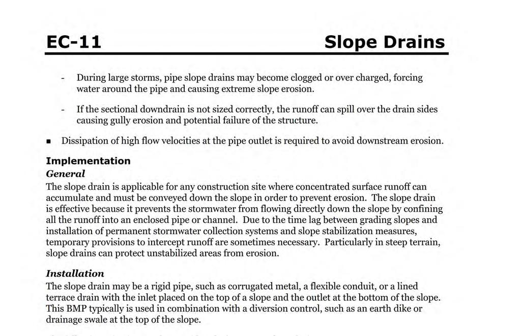
244 3-240
245 3-241
246 3-242
247 3-243
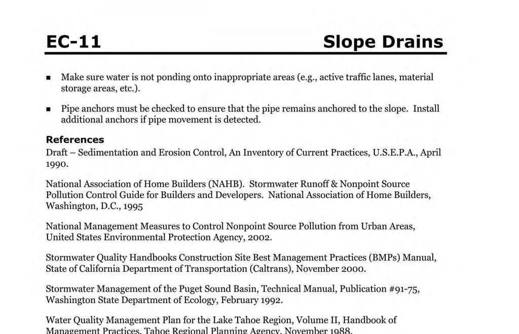
248 3-244
249 3-245
250 3-246
251 Soil Binders Soil Binders (EC-5) Categories EC-5 EC Erosion Control SE Sediment Control TC Tracking Control WE Wind Erosion Control NS Non-Stormwater Management Control WM Waste Management and Materials Pollution Control Legend: Primary Category Secondary Category Description and Purpose Soil binding consists of application and maintenance of a soil stabilizer to exposed soil surfaces. Soil binders are materials applied to the soil surface to temporarily prevent water and wind induced erosion of exposed soils on construction sites. Suitable Applications Soil binders are typically applied to disturbed areas requiring temporary protection. Because soil binders, when used as a stand-alone practice, can often be incorporated into the soil, they are a good alternative to mulches in areas where grading activities will soon resume. Soil binders are commonly used in the following areas: Rough graded soils that will be inactive for a short period of time Soil stockpiles Temporary haul roads prior to placement of crushed rock Compacted soil road base Construction staging, materials storage, and layout areas Targeted Constituents Sediment Nutrients Trash Metals Bacteria Oil and Grease Organics Potential Alternatives EC-3 Hydraulic Mulch EC-4 Hydroseeding EC-6 Straw Mulch EC-7 Geotextiles and Mats EC-8 Wood Mulching If User/Subscriber modifies this fact sheet in any way, the CASQA name/logo and footer below must be removed from each page and not appear on the modified version. Limitations Soil binders are temporary in nature and may need reapplication. Soil binders require a minimum curing time until fully effective, as prescribed by the manufacturer. Curing time July 2012 California Stormwater BMP Handbook 1 of 8 Construction
252 Soil Binders EC-5 may be 24 hours or longer. Soil binders may need reapplication after a storm event. Soil binders will generally experience spot failures during heavy rainfall events. If runoff penetrates the soil at the top of a slope treated with a soil binder, it is likely that the runoff will undercut the stabilized soil layer and discharge at a point further down slope. Plant-material-based soil binders do not generally hold up to pedestrian or vehicular traffic across treated areas as well as polymeric emulsion blends or cementitious-based binders. Soil binders may not sufficiently penetrate compacted soils. Some soil binders are soil texture specific in terms of their effectiveness. For example, polyacrylamides (PAMs) work very well on silt and clayey soils but their performance decreases dramatically in sandy soils. Some soil binders may not perform well with low relative humidity. Under rainy conditions, some agents may become slippery or leach out of the soil. Soil binders may not cure if low temperatures occur within 24 hours of application. The water quality impacts of some chemical soil binders are relatively unknown and some may have water quality impacts due to their chemical makeup. Additionally, these chemical may require non-visible pollutant monitoring. Products should be evaluated for projectspecific implementation by the SWPPP Preparer. Refer to the product Material Safety Data Sheet for chemical properties. Implementation General Considerations Soil binders should conform to local municipality specifications and requirements. Site soil types will dictate appropriate soil binders to be used. A soil binder must be environmentally benign (non-toxic to plant and animal life), easy to apply, easy to maintain, economical, and should not stain paved or painted surfaces. Soil binders should not pollute stormwater when cured. Obtain a Material Safety Data Sheet (MSDS) from the manufacturer to ensure non-toxicity. Stormwater runoff from PAM treated soils should pass through one of the following sediment control BMP prior to discharging to surface waters. When the total drainage area is greater than or equal to 5 acres, PAM treated areas should drain to a sediment basin. Areas less than 5 acres should drain to sediment control BMPs, such as a sediment trap, or a series of check dams. The total number of check dams used should be maximized to achieve the greatest amount of settlement of sediment prior to discharging from the site. Each check dam should be spaced evenly in the drainage channel through which stormwater flows are discharged off site. July 2012 California Stormwater BMP Handbook 2 of 8 Construction
253 Soil Binders EC-5 Performance of soil binders depends on temperature, humidity, and traffic across treated areas. Avoid over spray onto roads, sidewalks, drainage channels, existing vegetation, etc. Additional guidance on the comparison and selection of temporary slope stabilization methods is provided in Appendix F of the Handbook. Selecting a Soil Binder Properties of common soil binders used for erosion control are provided on Table 1 at the end of this Fact Sheet. Use Table 1 to select an appropriate soil binder. Refer to WE-1, Wind Erosion Control, for dust control soil binders. Factors to consider when selecting a soil binder include the following: Suitability to situation - Consider where the soil binder will be applied, if it needs a high resistance to leaching or abrasion, and whether it needs to be compatible with any existing vegetation. Determine the length of time soil stabilization will be needed, and if the soil binder will be placed in an area where it will degrade rapidly. In general, slope steepness is not a discriminating factor for the listed soil binders. Soil types and surface materials - Fines and moisture content are key properties of surface materials. Consider a soil binder's ability to penetrate, likelihood of leaching, and ability to form a surface crust on the surface materials. Frequency of application - The frequency of application is related to the functional longevity of the binder, which can be affected by subgrade conditions, surface type, climate, and maintenance schedule. Frequent applications could lead to high costs. Application frequency may be minimized if the soil binder has good penetration, low evaporation, and good longevity. Consider also that frequent application will require frequent equipment clean up. Plant-Material-Based (Short Lived, <6 months) Binders Guar: Guar is a non-toxic, biodegradable, natural galactomannan-based hydrocolloid treated with dispersant agents for easy field mixing. It should be mixed with water at the rate of 11 to 15 lb per 1,000 gallons. Recommended minimum application rates are as follows: Application Rates for Guar Soil Stabilizer Slope (H:V): Flat 4:1 3:1 2:1 1:1 lb/acre: Psyllium: Psyllium is composed of the finely ground muciloid coating of plantago seeds that is applied as a dry powder or in a wet slurry to the surface of the soil. It dries to form a firm but rewettable membrane that binds soil particles together, but permits germination and growth of seed. Psyllium requires 12 to 18 hours drying time. Application rates should be from 80 to 200 lb/acre, with enough water in solution to allow for a uniform slurry flow. July 2012 California Stormwater BMP Handbook 3 of 8 Construction
254 Soil Binders EC-5 Starch: Starch is non-ionic, cold water soluble (pre-gelatinized) granular cornstarch. The material is mixed with water and applied at the rate of 150 lb/acre. Approximate drying time is 9 to 12 hours. Plant-Material-Based (Long Lived, 6-12 months) Binders Pitch and Rosin Emulsion: Generally, a non-ionic pitch and rosin emulsion has a minimum solids content of 48%. The rosin should be a minimum of 26% of the total solids content. The soil stabilizer should be non-corrosive, water dilutable emulsion that upon application cures to a water insoluble binding and cementing agent. For soil erosion control applications, the emulsion is diluted and should be applied as follows: For clayey soil: 5 parts water to 1 part emulsion For sandy soil: 10 parts water to 1 part emulsion Application can be by water truck or hydraulic seeder with the emulsion and product mixture applied at the rate specified by the manufacturer. Polymeric Emulsion Blend Binders Acrylic Copolymers and Polymers: Polymeric soil stabilizers should consist of a liquid or solid polymer or copolymer with an acrylic base that contains a minimum of 55% solids. The polymeric compound should be handled and mixed in a manner that will not cause foaming or should contain an anti-foaming agent. The polymeric emulsion should not exceed its shelf life or expiration date; manufacturers should provide the expiration date. Polymeric soil stabilizer should be readily miscible in water, non-injurious to seed or animal life, non-flammable, should provide surface soil stabilization for various soil types without totally inhibiting water infiltration, and should not re-emulsify when cured. The applied compound typically requires 12 to 24 hours drying time. Liquid copolymer should be diluted at a rate of 10 parts water to 1 part polymer and the mixture applied to soil at a rate of 1,175 gallons/acre. Liquid Polymers of Methacrylates and Acrylates: This material consists of a tackifier/sealer that is a liquid polymer of methacrylates and acrylates. It is an aqueous 100% acrylic emulsion blend of 40% solids by volume that is free from styrene, acetate, vinyl, ethoxylated surfactants or silicates. For soil stabilization applications, it is diluted with water in accordance with the manufacturer s recommendations, and applied with a hydraulic seeder at the rate of 20 gallons/acre. Drying time is 12 to 18 hours after application. Copolymers of Sodium Acrylates and Acrylamides: These materials are non-toxic, dry powders that are copolymers of sodium acrylate and acrylamide. They are mixed with water and applied to the soil surface for erosion control at rates that are determined by slope gradient: Slope Gradient (H:V) lb/acre Flat to 5: :1 to 3: :1 to 1: July 2012 California Stormwater BMP Handbook 4 of 8 Construction
255 Soil Binders EC-5 Poly-Acrylamide (PAM) and Copolymer of Acrylamide: Linear copolymer polyacrylamide for use as a soil binder is packaged as a dry flowable solid, as a liquid. Refer to the manufacturer s recommendation for dilution and application rates as they vary based on liquid or dry form, site conditions and climate. Limitations specific to PAM are as follows: Do not use PAM on a slope that flows into a water body without passing through a sediment trap or sediment basin. The specific PAM copolymer formulation must be anionic. Cationic PAM should not be used in any application because of known aquatic toxicity problems. Only the highest drinking water grade PAM, certified for compliance with ANSI/NSF Standard 60 for drinking water treatment, should be used for soil applications. PAM designated for erosion and sediment control should be water soluble or linear or non-cross linked. PAM should not be used as a stand-alone BMP to protect against water-based erosion. When combined with mulch, its effectiveness increases dramatically. Hydro-Colloid Polymers: Hydro-Colloid Polymers are various combinations of dry flowable poly-acrylamides, copolymers and hydro-colloid polymers that are mixed with water and applied to the soil surface at rates of 55 to 60 lb/acre. Drying times are 0 to 4 hours. Cementitious-Based Binders Gypsum: This is a formulated gypsum based product that readily mixes with water and mulch to form a thin protective crust on the soil surface. It is composed of high purity gypsum that is ground, calcined and processed into calcium sulfate hemihydrate with a minimum purity of 86%. It is mixed in a hydraulic seeder and applied at rates 4,000 to 12,000 lb/acre. Drying time is 4 to 8 hours. Applying Soil Binders After selecting an appropriate soil binder, the untreated soil surface must be prepared before applying the soil binder. The untreated soil surface must contain sufficient moisture to assist the agent in achieving uniform distribution. In general, the following steps should be followed: Follow manufacturer s written recommendations for application rates, pre-wetting of application area, and cleaning of equipment after use. Prior to application, roughen embankment and fill areas. Consider the drying time for the selected soil binder and apply with sufficient time before anticipated rainfall. Soil binders should not be applied during or immediately before rainfall. Avoid over spray onto roads, sidewalks, drainage channels, sound walls, existing vegetation, etc. July 2012 California Stormwater BMP Handbook 5 of 8 Construction
256 Soil Binders EC-5 Soil binders should not be applied to frozen soil, areas with standing water, under freezing or rainy conditions, or when the temperature is below 40 F during the curing period. More than one treatment is often necessary, although the second treatment may be diluted or have a lower application rate. Generally, soil binders require a minimum curing time of 24 hours before they are fully effective. Refer to manufacturer's instructions for specific cure time. For liquid agents: Crown or slope ground to avoid ponding. Uniformly pre-wet ground at 0.03 to 0.3 gal/yd 2 or according to manufacturer s recommendations. Apply solution under pressure. Overlap solution 6 to 12 in. Allow treated area to cure for the time recommended by the manufacturer; typically at least 24 hours. Apply second treatment before first treatment becomes ineffective, using 50% application rate. In low humidities, reactivate chemicals by re-wetting with water at 0.1 to 0.2 gal/yd 2. Costs Costs vary according to the soil stabilizer selected for implementation. The following are approximate installed costs: Soil Binder Estimated Cost Cost per Acre (2004) 1 per Acre (2009) 2 Plant-Material-Based (Short Lived) Binders $700-$900 $770-$990 Plant-Material-Based (Long Lived) Binders $1,200-$1,500 $1,320-$1,650 Polymeric Emulsion Blend Binders $700 -$1,500 $770-$1,650 Cementitious-Based Binders $800-$1,200 $880-$1, Source: Cost information received from individual product manufacturers solicited by Geosyntec Consultants (2004) costs reflect a 10% escalation over year 2004 costs. Escalation based on informal survey of industry trends. Note: Expected cost increase is offset by competitive economic conditions. Inspection and Maintenance BMPs must be inspected in accordance with General Permit requirements for the associated project type and risk level. It is recommended that at a minimum, BMPs be inspected weekly, prior to forecasted rain events, daily during extended rain events, and after the conclusion of rain events. July 2012 California Stormwater BMP Handbook 6 of 8 Construction
257 Soil Binders EC-5 Areas where erosion is evident should be repaired and BMPs re-applied as soon as possible. Care should be exercised to minimize the damage to protected areas while making repairs, as any area damaged will require re-application of BMPs. Reapply the selected soil binder as needed to maintain effectiveness. Table 1 Properties of Soil Binders for Erosion Control Binder Type Evaluation Criteria Plant Material Based (Short Lived) Plant Material Based (Long Lived) Polymeric Emulsion Blends Cementitious- Based Binders Relative Cost Low Moderate to High Low to High Low to Moderate Resistance to Leaching High High Low to Moderate Moderate Resistance to Abrasion Moderate Low Moderate to High Moderate to High Longevity Short to Medium Medium Medium to Long Medium Minimum Curing Time before Rain Compatibility with Existing Vegetation 9 to 18 hours 19 to 24 hours 0 to 24 hours 4 to 8 hours Mode of Degradation Biodegradable Biodegradable Good Poor Poor Poor Photodegradable/ Chemically Degradable Photodegradable/ Chemically Degradable Labor Intensive No No No No Specialized Application Equipment Water Truck or Hydraulic Mulcher Water Truck or Hydraulic Mulcher Water Truck or Hydraulic Mulcher Water Truck or Hydraulic Mulcher Liquid/Powder Powder Liquid Liquid/Powder Powder Surface Crusting Yes, but dissolves on rewetting Yes Yes, but dissolves on rewetting Yes Clean Up Water Water Water Water Erosion Control Application Rate Varies (1) Varies (1) Varies (1) 4,000 to 12,000 lbs/acre (1) See Implementation for specific rates. July 2012 California Stormwater BMP Handbook 7 of 8 Construction
258 Soil Binders EC-5 References Erosion Control Pilot Study Report, State of California Department of Transportation (Caltrans), June Manual of Standards of Erosion and Sediment Control Measures, Association of Bay Area Governments, May Sedimentation and Erosion Control, An Inventory of Current Practices Draft, US EPA, April Stormwater Quality Handbooks Construction Site Best Management Practices (BMPs) Manual, State of California Department of Transportation (Caltrans), March Guidance Document: Soil Stabilization for Temporary Slopes, State of California Department of Transportation (Caltrans), November Stormwater Management for Construction Activities, Developing Pollution Prevention Plans and Best Management Practices, EPA 832-R-92005; USEPA, April July 2012 California Stormwater BMP Handbook 8 of 8 Construction
259 Geotextiles and Mats Geotextiles and Mats (EC-7) Categories EC-7 EC Erosion Control SE Sediment Control TC Tracking Control WE Wind Erosion Control Non-Stormwater NS Management Control Waste Management and WM Materials Pollution Control Legend: Primary Category Secondary Category Description and Purpose Mattings, or Rolled Erosion Control Products (RECPs), can be made of natural or synthetic materials or a combination of the two. RECPs are used to cover the soil surface to reduce erosion from rainfall impact, hold soil in place, and absorb and hold moisture near the soil surface. Additionally, RECPs may be used to stabilize soils until vegetation is established or to reinforce non-woody surface vegetation. Suitable Applications RECPs are typically applied on slopes where erosion hazard is high and vegetation will be slow to establish. Mattings are also used on stream banks, swales and other drainage channels where moving water at velocities between 3 ft/s and 6 ft/s are likely to cause scour and wash out new vegetation, and in areas where the soil surface is disturbed and where existing vegetation has been removed. RECPs may also be used when seeding cannot occur (e.g., late season construction and/or the arrival of an early rain season). RECPs should be considered when the soils are fine grained and potentially erosive. RECPs should be considered in the following situations. Targeted Constituents Sediment Nutrients Trash Metals Bacteria Oil and Grease Organics Potential Alternatives EC-3 Hydraulic Mulch EC-4 Hydroseeding If User/Subscriber modifies this fact sheet in any way, the CASQA name/logo and footer below must be removed from each page and not appear on the modified version. Steep slopes, generally steeper than 3:1 (H:V) Slopes where the erosion potential is high Slopes and disturbed soils where mulch must be anchored Disturbed areas where plants are slow to develop July 2012 California Stormwater BMP Handbook 1 of 12 Construction
260 Geotextiles and Mats EC-7 Channels with flows exceeding 3.3 ft/s Channels to be vegetated Stockpiles Slopes adjacent to water bodies Limitations RECP installed costs are generally higher than other erosion control BMPs, limiting their use to areas where other BMPs are ineffective (e.g. channels, steep slopes). RECPs may delay seed germination, due to reduction in soil temperature. RECPs are generally not suitable for excessively rocky sites or areas where the final vegetation will be mowed (since staples and netting can catch in mowers). If a staple or pin cannot be driven into the soil because the underlying soil is too hard or rocky, then an alternative BMP should be selected. If used for temporary erosion control, RECPs should be removed and disposed of prior to application of permanent soil stabilization measures. The use of plastic should be limited to covering stockpiles or very small graded areas for short periods of time (such as through one imminent storm event) until more environmentally friendly measures, such as seeding and mulching, may be installed. - Plastic sheeting is easily vandalized, easily torn, photodegradable, and must be disposed of at a landfill. - Plastic sheeting results in 100% runoff, which may cause serious erosion problems in the areas receiving the increased flow. RECPs may have limitations based on soil type, slope gradient, or channel flow rate; consult the manufacturer for proper selection. Not suitable for areas that have foot traffic (tripping hazard) e.g., pad areas around buildings under construction. RECPs that incorporate a plastic netting (e.g. straw blanket typically uses a plastic netting to hold the straw in place) may not be suitable near known wildlife habitat. Wildlife can become trapped in the plastic netting. RECPs may have limitations in extremely windy climates. However, when RECPs are properly trenched at the top and bottom and stapled in accordance with the manufacturer s recommendations, problems with wind can be minimized. July 2012 California Stormwater BMP Handbook 2 of 12 Construction
261 Geotextiles and Mats EC-7 Implementation Material Selection Natural RECPs have been found to be effective where re-vegetation will be provided by reseeding. The choice of material should be based on the size of area, side slopes, surface conditions such as hardness, moisture, weed growth, and availability of materials. Additional guidance on the comparison and selection of temporary slope stabilization methods is provided in Appendix F of the Handbook. The following natural and synthetic RECPs are commonly used: Geotextiles Material can be a woven or a non-woven polypropylene fabric with minimum thickness of 0.06 in., minimum width of 12 ft and should have minimum tensile strength of 150 lbs (warp), 80 lbs (fill) in conformance with the requirements in ASTM Designation: D The permittivity of the fabric should be approximately 0.07 sec 1 in conformance with the requirements in ASTM Designation: D4491. The fabric should have an ultraviolet (UV) stability of 70 percent in conformance with the requirements in ASTM designation: D4355. Geotextile blankets must be secured in place with wire staples or sandbags and by keying into tops of slopes to prevent infiltration of surface waters under geotextile. Staples should be made of minimum 11 gauge steel wire and should be U-shaped with 8 in. legs and 2 in. crown. Geotextiles may be reused if they are suitable for the use intended. Plastic Covers Generally plastic sheeting should only be used as stockpile covering or for very small graded areas for short periods of time (such as through one imminent storm event). If plastic sheeting must be used, choose a plastic that will withstand photo degradation. Plastic sheeting should have a minimum thickness of 6 mils, and must be keyed in at the top of slope (when used as a temporary slope protection) and firmly held in place with sandbags or other weights placed no more than 10 ft apart. Seams are typically taped or weighted down their entire length, and there should be at least a 12 in. to 24 in. overlap of all seams. Edges should be embedded a minimum of 6 in. in soil (when used as a temporary slope protection). All sheeting must be inspected periodically after installation and after significant rainstorms to check for erosion, undermining, and anchorage failure. Any failures must be repaired immediately. If washout or breakages occur, the material should be re-installed after repairing the damage to the slope. Erosion Control Blankets/Mats Biodegradable RECPs are typically composed of jute fibers, curled wood fibers, straw, coconut fiber, or a combination of these materials. In order for an RECP to be considered 100% biodegradable, the netting, sewing or adhesive system that holds the biodegradable mulch fibers together must also be biodegradable. See typical installation details at the end of this fact sheet. July 2012 California Stormwater BMP Handbook 3 of 12 Construction
262 Geotextiles and Mats EC-7 - Jute is a natural fiber that is made into a yarn that is loosely woven into a biodegradable mesh. The performance of jute as a stand-alone RECP is low. Most other RECPs outperform jute as a temporary erosion control product and therefore jute is not commonly used. It is designed to be used in conjunction with vegetation. The material is supplied in rolled strips, which should be secured to the soil with U-shaped staples or stakes in accordance with manufacturers recommendations. - Excelsior (curled wood fiber) blanket material should consist of machine produced mats of curled wood excelsior with 80 percent of the fiber 6 in. or longer. The excelsior blanket should be of consistent thickness. The wood fiber must be evenly distributed over the entire area of the blanket. The top surface of the blanket should be covered with a photodegradable extruded plastic mesh. The blanket should be smolder resistant without the use of chemical additives and should be non-toxic and non-injurious to plant and animal life. Excelsior blankets should be furnished in rolled strips, a minimum of 48 in. wide, and should have an average weight of 0.8 lb/yd 2, 10 percent, at the time of manufacture. Excelsior blankets must be secured in place with wire staples. Staples should be made of minimum 11 gauge steel wire and should be U-shaped with 8 in. legs and 2 in. crown. - Straw blanket should be machine produced mats of straw with a lightweight biodegradable netting top layer. The straw should be attached to the netting with biodegradable thread or glue strips. The straw blanket should be of consistent thickness. The straw should be evenly distributed over the entire area of the blanket. Straw blanket should be furnished in rolled strips a minimum of 6.5 ft wide, a minimum of 80 ft long and a minimum of 0.5 lb/yd 2. Straw blankets must be secured in place with wire staples. Staples should be made of minimum 11 gauge steel wire and should be U-shaped with 8 in. legs and 2 in. crown. - Wood fiber blanket is composed of biodegradable fiber mulch with extruded plastic netting held together with adhesives. The material is designed to enhance re-vegetation. The material is furnished in rolled strips, which must be secured to the ground with U- shaped staples or stakes in accordance with manufacturers recommendations. - Coconut fiber blanket should be a machine produced mat of 100 percent coconut fiber with biodegradable netting on the top and bottom. The coconut fiber should be attached to the netting with biodegradable thread or glue strips. The coconut fiber blanket should be of consistent thickness. The coconut fiber should be evenly distributed over the entire area of the blanket. Coconut fiber blanket should be furnished in rolled strips with a minimum of 6.5 ft wide, a minimum of 80 ft. long and a minimum of 0.5 lb/yd 2. Coconut fiber blankets must be secured in place with wire staples. Staples should be made of minimum 11 gauge steel wire and should be U-shaped with 8 in. legs and 2 in. crown. - Coconut fiber mesh is a thin permeable membrane made from coconut or corn fiber that is spun into a yarn and woven into a biodegradable mat. It is designed to be used in conjunction with vegetation and typically has longevity of several years. The material is supplied in rolled strips, which must be secured to the soil with U-shaped staples or stakes in accordance with manufacturers recommendations. July 2012 California Stormwater BMP Handbook 4 of 12 Construction
263 Geotextiles and Mats EC-7 - Straw coconut fiber blanket should be machine produced mats of 70 percent straw and 30 percent coconut fiber with a biodegradable netting top layer and a biodegradable bottom net. The straw and coconut fiber should be attached to the netting with biodegradable thread or glue strips. The straw coconut fiber blanket should be of consistent thickness. The straw and coconut fiber should be evenly distributed over the entire area of the blanket. Straw coconut fiber blanket should be furnished in rolled strips a minimum of 6.5 ft wide, a minimum of 80 ft long and a minimum of 0.5 lb/yd 2. Straw coconut fiber blankets must be secured in place with wire staples. Staples should be made of minimum 11 gauge steel wire and should be U-shaped with 8 in. legs and 2 in. crown. Non-biodegradable RECPs are typically composed of polypropylene, polyethylene, nylon or other synthetic fibers. In some cases, a combination of biodegradable and synthetic fibers is used to construct the RECP. Netting used to hold these fibers together is typically nonbiodegradable as well. - Plastic netting is a lightweight biaxially oriented netting designed for securing loose mulches like straw or paper to soil surfaces to establish vegetation. The netting is photodegradable. The netting is supplied in rolled strips, which must be secured with U- shaped staples or stakes in accordance with manufacturers recommendations. - Plastic mesh is an open weave geotextile that is composed of an extruded synthetic fiber woven into a mesh with an opening size of less than ¼ in. It is used with revegetation or may be used to secure loose fiber such as straw to the ground. The material is supplied in rolled strips, which must be secured to the soil with U-shaped staples or stakes in accordance with manufacturers recommendations. - Synthetic fiber with netting is a mat that is composed of durable synthetic fibers treated to resist chemicals and ultraviolet light. The mat is a dense, three dimensional mesh of synthetic (typically polyolefin) fibers stitched between two polypropylene nets. The mats are designed to be re-vegetated and provide a permanent composite system of soil, roots, and geomatrix. The material is furnished in rolled strips, which must be secured with U-shaped staples or stakes in accordance with manufacturers recommendations. - Bonded synthetic fibers consist of a three dimensional geomatrix nylon (or other synthetic) matting. Typically it has more than 90 percent open area, which facilitates root growth. It s tough root reinforcing system anchors vegetation and protects against hydraulic lift and shear forces created by high volume discharges. It can be installed over prepared soil, followed by seeding into the mat. Once vegetated, it becomes an invisible composite system of soil, roots, and geomatrix. The material is furnished in rolled strips that must be secured with U-shaped staples or stakes in accordance with manufacturers recommendations. - Combination synthetic and biodegradable RECPs consist of biodegradable fibers, such as wood fiber or coconut fiber, with a heavy polypropylene net stitched to the top and a high strength continuous filament geomatrix or net stitched to the bottom. The material is designed to enhance re-vegetation. The material is furnished in rolled strips, July 2012 California Stormwater BMP Handbook 5 of 12 Construction
264 Geotextiles and Mats EC-7 which must be secured with U-shaped staples or stakes in accordance with manufacturers recommendations. Site Preparation Proper soil preparation is essential to ensure complete contact of the RECP with the soil. Soil Roughening is not recommended in areas where RECPs will be installed. Grade and shape the area of installation. Remove all rocks, clods, vegetation or other obstructions so that the installed blankets or mats will have complete, direct contact with the soil. Prepare seedbed by loosening 2 to 3 in. of topsoil. Seeding/Planting Seed the area before blanket installation for erosion control and re-vegetation. Seeding after mat installation is often specified for turf reinforcement application. When seeding prior to blanket installation, all areas disturbed during blanket installation must be re-seeded. Where soil filling is specified for turf reinforcement mats (TRMs), seed the matting and the entire disturbed area after installation and prior to filling the mat with soil. Fertilize and seed in accordance with seeding specifications or other types of landscaping plans. The protective matting can be laid over areas where grass has been planted and the seedlings have emerged. Where vines or other ground covers are to be planted, lay the protective matting first and then plant through matting according to design of planting. Check Slots Check slots shall be installed as required by the manufacturer. Laying and Securing Matting Before laying the matting, all check slots should be installed and the seedbed should be friable, made free from clods, rocks, and roots. The surface should be compacted and finished according to the requirements of the manufacturer s recommendations. Mechanical or manual lay down equipment should be capable of handling full rolls of fabric and laying the fabric smoothly without wrinkles or folds. The equipment should meet the fabric manufacturer s recommendations or equivalent standards. Anchoring U-shaped wire staples, metal geotextile stake pins, or triangular wooden stakes can be used to anchor mats and blankets to the ground surface. Wire staples should be made of minimum 11 gauge steel wire and should be U-shaped with 8 in. legs and 2 in. crown. Metal stake pins should be in. diameter steel with a 1.5 in. steel washer at the head of the pin, and 8 in. in length. Wire staples and metal stakes should be driven flush to the soil surface. July 2012 California Stormwater BMP Handbook 6 of 12 Construction
265 Geotextiles and Mats EC-7 Installation on Slopes Installation should be in accordance with the manufacturer's recommendations. In general, these will be as follows: Begin at the top of the slope and anchor the blanket in a 6 in. deep by 6 in. wide trench. Backfill trench and tamp earth firmly. Unroll blanket down slope in the direction of water flow. Overlap the edges of adjacent parallel rolls 2 to 3 in. and staple every 3 ft (or greater, per manufacturer s specifications). When blankets must be spliced, place blankets end over end (shingle style) with 6 in. overlap. Staple through overlapped area, approximately 12 in. apart. Lay blankets loosely and maintain direct contact with the soil. Do not stretch. Staple blankets sufficiently to anchor blanket and maintain contact with the soil. Staples should be placed down the center and staggered with the staples placed along the edges. Steep slopes, 1:1 (H:V) to 2:1 (H:V), require a minimum of 2 staples/yd 2. Moderate slopes, 2:1 (H:V) to 3:1 (H:V), require a minimum of 1 ½ staples/yd 2. Check manufacturer s specifications to determine if a higher density staple pattern is required. Installation in Channels Installation should be in accordance with the manufacturer's recommendations. In general, these will be as follows: Dig initial anchor trench 12 in. deep and 6 in. wide across the channel at the lower end of the project area. Excavate intermittent check slots, 6 in. deep and 6 in. wide across the channel at 25 to 30 ft intervals along the channels. Cut longitudinal channel anchor trenches 4 in. deep and 4 in. wide along each side of the installation to bury edges of matting, whenever possible extend matting 2 to 3 in. above the crest of the channel side slopes. Beginning at the downstream end and in the center of the channel, place the initial end of the first roll in the anchor trench and secure with fastening devices at 12 in. intervals. Note: matting will initially be upside down in anchor trench. In the same manner, position adjacent rolls in anchor trench, overlapping the preceding roll a minimum of 3 in. Secure these initial ends of mats with anchors at 12 in. intervals, backfill and compact soil. Unroll center strip of matting upstream. Stop at next check slot or terminal anchor trench. Unroll adjacent mats upstream in similar fashion, maintaining a 3 in. overlap. July 2012 California Stormwater BMP Handbook 7 of 12 Construction
266 Geotextiles and Mats EC-7 Fold and secure all rolls of matting snugly into all transverse check slots. Lay mat in the bottom of the slot then fold back against itself. Anchor through both layers of mat at 12 in. intervals, then backfill and compact soil. Continue rolling all mat widths upstream to the next check slot or terminal anchor trench. Alternate method for non-critical installations: Place two rows of anchors on 6 in. centers at 25 to 30 ft. intervals in lieu of excavated check slots. Staple shingled lap spliced ends a minimum of 12 in. apart on 12 in. intervals. Place edges of outside mats in previously excavated longitudinal slots; anchor using prescribed staple pattern, backfill, and compact soil. Anchor, fill, and compact upstream end of mat in a 12 in. by 6 in. terminal trench. Secure mat to ground surface using U-shaped wire staples, geotextile pins, or wooden stakes. Seed and fill turf reinforcement matting with soil, if specified. Soil Filling (if specified for turf reinforcement mat (TRM)) Installation should be in accordance with the manufacturer s recommendations. Typical installation guidelines are as follows: After seeding, spread and lightly rake ½-3/4 inches of fine topsoil into the TRM apertures to completely fill TRM thickness. Use backside of rake or other flat implement. Alternatively, if allowed by product specifications, spread topsoil using lightweight loader, backhoe, or other power equipment. Avoid sharp turns with equipment. Always consult the manufacturer's recommendations for installation. Do not drive tracked or heavy equipment over mat. Avoid any traffic over matting if loose or wet soil conditions exist. Use shovels, rakes, or brooms for fine grading and touch up. Smooth out soil filling just exposing top netting of mat. Temporary Soil Stabilization Removal Temporary soil stabilization removed from the site of the work must be disposed of if necessary. Costs Installed costs can be relatively high compared to other BMPs. Approximate costs for installed materials are shown below: July 2012 California Stormwater BMP Handbook 8 of 12 Construction
267 Geotextiles and Mats EC-7 Biodegradable Non-Biodegradable Rolled Erosion Control Products Installed Cost per Acre (2004) 1 Estimated Cost per Acre (2009) 2 Jute Mesh $6,000-$7,000 $6,600-$7,700 Curled Wood Fiber $8,000-$10,500 $8,800-$11,050 Straw $8,000-$10,500 $8,800-$11,050 Wood Fiber $8,000-$10,500 $8,800-$11,050 Coconut Fiber $13,000-$14,000 $14,300-$15,400 Coconut Fiber Mesh $30,000-$33,000 $33,000-$36,300 Straw Coconut Fiber $10,000-$12,000 $11,000-$13,200 Plastic Netting $2,000-$2,200 $2,200-$2,220 Plastic Mesh $3,000-$3,500 $3,300-$3,850 Synthetic Fiber with Netting $34,000-$40,000 $37,400-$44,000 Bonded Synthetic Fibers $45,000-$55,000 $49,500-$60,500 Combination with Biodegradable $30,000-$36,000 $33,000-$39, Source: Cost information received from individual product manufacturers solicited by Geosyntec Consultants (2004) costs reflect a 10% escalation over year 2004 costs. Escalation based on informal survey of industry trends. Note: Expected cost increase is offset by competitive economic conditions. Inspection and Maintenance RECPs must be inspected in accordance with General Permit requirements for the associated project type and risk level. It is recommended that at a minimum, BMPs be inspected weekly, prior to forecasted rain events, daily during extended rain events, and after the conclusion of rain events. Areas where erosion is evident shall be repaired and BMPs reapplied as soon as possible. Care should be exercised to minimize the damage to protected areas while making repairs, as any area damaged will require reapplication of BMPs. If washout or breakage occurs, re-install the material after repairing the damage to the slope or channel. Make sure matting is uniformly in contact with the soil. Check that all the lap joints are secure. Check that staples are flush with the ground. References Erosion and Sediment Control Manual, Oregon Department of Environmental Quality, February 2005 Erosion Control Pilot Study Report, State of California Department of Transportation (Caltrans), June Guides for Erosion and Sediment Controls in California, USDA Soils Conservation Service, January July 2012 California Stormwater BMP Handbook 9 of 12 Construction
268 Geotextiles and Mats EC-7 National Management Measures to Control Nonpoint Source Pollution from Urban Areas, United States Environmental Protection Agency, Stormwater Quality Handbooks Construction Site Best Management Practices (BMPs) Manual, State of California Department of Transportation (Caltrans), March Guidance Document: Soil Stabilization for Temporary Slopes, State of California Department of Transportation (Caltrans), November Stormwater Management of the Puget Sound Basin, Technical Manual, Publication #91-75, Washington State Department of Ecology, February Water Quality Management Plan for The Lake Tahoe Region, Volume II, Handbook of Management Practices, Tahoe Regional Planning Agency, November July 2012 California Stormwater BMP Handbook 10 of 12 Construction
269 Geotextiles and Mats EC-7 July 2012 California Stormwater BMP Handbook 11 of 12 Construction
270 Geotextiles and Mats EC-7 July 2012 California Stormwater BMP Handbook 12 of 12 Construction
271 Hydraulic Mulch Hydraulic Mulch (EC-3) Categories EC-3 EC Erosion Control SE Sediment Control TC Tracking Control WE Wind Erosion Control NS Non-Stormwater Management Control WM Waste Management and Materials Pollution Control Legend: Primary Category Secondary Category Description and Purpose Hydraulic Mulch consists of various types of fibrous materials mixed with water and sprayed onto the soil surface in slurry form to provide a layer of temporary protection from wind and water erosion. Suitable Applications Hydraulic mulch as a temporary, stand alone, erosion control BMP is suitable for disturbed areas that require temporary protection from wind and water erosion until permanent soil stabilization activities commence. Examples include: Rough-graded areas that will remain inactive for longer than permit-required thresholds (e.g., 14 days) or otherwise require stabilization to minimize erosion or prevent sediment discharges. Soil stockpiles. Slopes with exposed soil between existing vegetation such as trees or shrubs. Slopes planted with live, container-grown vegetation or plugs. Slopes burned by wildfire. Targeted Constituents Sediment Nutrients Trash Metals Bacteria Oil and Grease Organics Potential Alternatives EC-4 Hydroseeding EC-5 Soil Binders EC-6 Straw Mulch EC-7 Geotextiles and Mats EC-8 Wood Mulching EC-14 Compost Blanket EC-16 Non-Vegetative Stabilization If User/Subscriber modifies this fact sheet in any way, the CASQA name/logo and footer below must be removed from each page and not appear on the modified version. July 2012 California Stormwater BMP Handbook 1 of 5 Construction
272 Hydraulic Mulch EC-3 Hydraulic mulch can also be applied to augment other erosion control BMPs such as: In conjunction with straw mulch (see EC-6 Straw Mulch) where the rate of hydraulic mulch is reduced to lbs per acre and the slurry is applied over the straw as a tackifying agent to hold the straw in place. Supplemental application of soil amendments, such as fertilizer, lime, gypsum, soil biostimulants or compost. Limitations In general, hydraulic mulch is not limited by slope length, gradient or soil type. However, the following limitations typically apply: Most hydraulic mulch applications, particularly bonded fiber matrices (BFMs), require at least 24 hours to dry before rainfall occurs. Temporary applications (i.e., without a vegetative component) may require a second application in order to remain effective for an entire rainy season. Treatment areas must be accessible to hydraulic mulching equipment. Availability of water sources in remote areas for mixing and application. As a stand-alone temporary BMP, hydraulic mulches may need to be re-applied to maintain their erosion control effectiveness, typically after 6-12 months depending on the type of mulch used. Availability of hydraulic mulching equipment may be limited just prior to the rainy season and prior to storms due to high demand. Cellulose fiber mulches alone may not perform well on steep slopes or in course soils. This BMP consists of a mixture of several constituents (e.g., fibers/mulches, tackifiers, and other chemical constituents), some of which may be proprietary and may come pre-mixed by the manufacturer. The water quality impacts of these constituents are relatively unknown and some may have water quality impacts due to their chemical makeup. Refer to specific chemical properties identified in the product Material Safety Data Sheet; products should be evaluated for project-specific implementation by the SWPPP Preparer. Refer to factsheet EC-05 for further guidance on selecting soil binders. Implementation Where feasible, it is preferable to prepare soil surfaces prior to application by roughening embankments and fill areas with a crimping or punching type roller or by track walking. The majority of hydraulic mulch applications do not necessarily require surface/soil preparation (See EC-15 Soil Preparation) although in almost every case where re-vegetation is included as part of the practice, soil preparation can be beneficial. One of the advantages of hydraulic mulch over other erosion control methods is that it can be applied in areas where soil preparation is precluded by site conditions, such as steep slopes, rocky soils, or inaccessibility. July 2012 California Stormwater BMP Handbook 2 of 5 Construction
273 Hydraulic Mulch EC-3 Avoid mulch over spray onto roads, sidewalks, drainage channels, existing vegetation, etc. Hydraulic mulching is generally performed utilizing specialized machines that have a large water-holding/mixing tank and some form of mechanical agitation or other recirculation method to keep water, mulch and soil amendments in suspension. The mixed hydraulic slurry can be applied from a tower sprayer on top of the machine or by extending a hose to areas remote from the machine. Where possible apply hydraulic mulch from multiple directions to adequately cover the soil. Application from a single direction can result in shadowing, uneven coverage and failure of the BMP. Hydraulic mulch can also include a vegetative component, such as seed, rhizomes, or stolons (see EC-4 Hydraulic Seed). Typical hydraulic mulch application rates range from 2,000 pounds per acre for standard mulches (SMs) to 3,500 pounds per acre for BFMs. However, the required amount of hydraulic mulch to provide adequate coverage of exposed topsoil may appear to exceed the standard rates when the roughness of the soil surface is changed due to soil preparation methods (see EC-15 Soil Preparation) or by slope gradient. Other factors such as existing soil moisture and soil texture can have a profound effect on the amount of hydraulic mulch required (i.e. application rate) applied to achieve an erosionresistant covering. Avoid use of mulch without a tackifier component, especially on slopes. Mulches used in the hydraulic mulch slurry can include: Cellulose fiber Thermally-processed wood fibers Cotton Synthetics Compost (see EC-14, Compost Blanket) Additional guidance on the comparison and selection of temporary slope stabilization methods is provided in Appendix F of the Handbook. Categories of Hydraulic Mulches Standard Hydraulic Mulch (SM) Standard hydraulic mulches are generally applied at a rate of 2,000 pounds per acre and are manufactured containing around 5% tackifier (i.e. soil binder), usually a plant-derived guar or psyllium type. Most standard mulches are green in color derived from food-color based dyes. July 2012 California Stormwater BMP Handbook 3 of 5 Construction
274 Hydraulic Mulch EC-3 Hydraulic Matrices (HM) and Stabilized Fiber Matrices (SFM) Hydraulic matrices and stabilized fiber matrices are slurries which contain increased levels of tackifiers/soil binders; usually 10% or more by weight. HMs and SFMs have improved performance compared to a standard hydraulic mulch (SM) because of the additional percentage of tackifier and because of their higher application rates, typically 2,500 4,000 pounds per acre. Hydraulic matrices can include a mixture of fibers, for example, a 50/50 blend of paper and wood fiber. In the case of an SFM, the tackifier/soil binder is specified as a polyacrylamide (PAM). Bonded Fiber Matrix (BFM) Bonded fiber matrices (BFMs) are hydraulically-applied systems of fibers, adhesives (typically guar based) and chemical cross-links. Upon drying, the slurry forms an erosion-resistant blanket that prevents soil erosion and promotes vegetation establishment. The cross-linked adhesive in the BFM should be biodegradable and should not dissolve or disperse upon rewetting. BFMs are typically applied at rates from 3,000 to 4,000 lbs/acre based on the manufacturer s recommendation. BFMs should not be applied immediately before, during or immediately after rainfall or if the soil is saturated. Depending on the product, BFMs typically require 12 to 24 hours to dry and become effective. Mechanically-Bonded Fiber Matrices (MBFM) Mechanically-bonded fiber matrices (MBFMs) are hydraulically applied systems similar to BFM that use crimped synthetic fibers and PAM and are typically applied to a slope at a higher application rate than a standard BFM. Hydraulic Compost Matrix (HCM) Hydraulic compost matrix (HCM) is a field-derived practice whereby finely graded or sifted compost is introduced into the hydraulic mulch slurry. A guar-type tackifier can be added for steeper slope applications as well as any specified seed mixtures. A HCM can help to accelerate seed germination and growth. HCMs are particularly useful as an in-fill for three-dimensional re-vegetation geocomposites, such as turf reinforcement mats (TRM) (see EC-7 Geotextiles and Mats). Costs Average installed costs for hydraulic mulch categories are is provided in Table 1, below. Table 1 HYDRAULIC MULCH BMPs INSTALLED COSTS BMP Installed Cost/Acre Standard Hydraulic Mulching (SM) Hydraulic Matrices (HM) and Stabilized Fiber Matrices Guar-based PAM-based Bonded Fiber Matrix (BFM) Mechanically Bonded Fiber Matrix (MBFM) Hydraulic Compost Matrix (HCM) $1,700 - $3,600 per acre $2,000 - $4,000 per acre $2,500 - $5,610 per acre $3,900 - $6,900 per acre $4,500 - $6,000 per acre $3,000 - $3,500 per acre July 2012 California Stormwater BMP Handbook 4 of 5 Construction
275 Hydraulic Mulch EC-3 Source: Cost information received from individual product manufacturers solicited by Geosyntec Consultants (2004) Inspection and Maintenance Maintain an unbroken, temporary mulched ground cover throughout the period of construction when the soils are not being reworked. BMPs must be inspected in accordance with General Permit requirements for the associated project type and risk level. It is recommended that at a minimum, BMPs be inspected weekly, prior to forecasted rain events, daily during extended rain events, and after the conclusion of rain events. Areas where erosion is evident should be repaired and BMPs re-applied as soon as possible. Care should be exercised to minimize the damage to protected areas while making repairs, as any area damaged will require re-application of BMPs. Compare the number of bags or weight of applied mulch to the area treated to determine actual application rates and compliance with specifications. References Soil Stabilization BMP Research for Erosion and Sediment Controls: Cost Survey Technical Memorandum, State of California Department of Transportation (Caltrans), July Controlling Erosion of Construction Sites, Agricultural Information #347, U.S. Department of Agriculture (USDA), Natural Resources Conservation Service (NRCS) (formerly Soil Conservation Service SCS). Guides for Erosion and Sediment Control in California, USDA Soils Conservation Service, January Manual of Standards of Erosion and Sediment Control Measures, Association of Bay Area Governments, May Sedimentation and Erosion Control, An Inventory of Current Practices Draft, US EPA, April Soil Erosion by Water, Agriculture Information Bulletin #513, U.S. Department of Agriculture, Soil Conservation Service. Stormwater Quality Handbooks Construction Site Best Management Practices (BMPs) Manual, State of California Department of Transportation (Caltrans), March Guidance Document: Soil Stabilization for Temporary Slopes, State of California Department of Transportation (Caltrans), November 1999 Stormwater Management of the Puget Sound Basin, Technical Manual, Publication #91-75, Washington State Department of Ecology, February Water Quality Management Plan for the Lake Tahoe Region, Volume II, Handbook of Management Practices, Tahoe Regional Planning Agency, November July 2012 California Stormwater BMP Handbook 5 of 5 Construction
276 3-272
277 Hydroseeding Hydroseeding (EC-4) Categories EC-4 EC Erosion Control SE Sediment Control TC Tracking Control WE Wind Erosion Control NS Non-Stormwater Management Control WM Waste Management and Materials Pollution Control Legend: Primary Category Secondary Category Description and Purpose Hydroseeding typically consists of applying a mixture of a hydraulic mulch, seed, fertilizer, and stabilizing emulsion with a hydraulic mulcher, to temporarily protect exposed soils from erosion by water and wind. Hydraulic seeding, or hydroseeding, is simply the method by which temporary or permanent seed is applied to the soil surface. Suitable Applications Hydroseeding is suitable for disturbed areas requiring temporary protection until permanent stabilization is established, for disturbed areas that will be re-disturbed following an extended period of inactivity, or to apply permanent stabilization measures. Hydroseeding without mulch or other cover (e.g. EC-7, Erosion Control Blanket) is not a stand-alone erosion control BMP and should be combined with additional measures until vegetation establishment. Typical applications for hydroseeding include: Disturbed soil/graded areas where permanent stabilization or continued earthwork is not anticipated prior to seed germination. Cleared and graded areas exposed to seasonal rains or temporary irrigation. Targeted Constituents Sediment Nutrients Trash Metals Bacteria Oil and Grease Organics Potential Alternatives EC-3 Hydraulic Mulch EC-5 Soil Binders EC-6 Straw Mulch EC-7 Geotextiles and Mats EC-8 Wood Mulching EC-14 Compost Blanket EC-16 Non-Vegetative Stabilization If User/Subscriber modifies this fact sheet in any way, the CASQA name/logo and footer below must be removed from each page and not appear on the modified version. Areas not subject to heavy wear by construction equipment or high traffic. July 2012 California Stormwater BMP Handbook 1 of 4 Construction
278 Hydroseeding EC-4 Limitations Availability of hydroseeding equipment may be limited just prior to the rainy season and prior to storms due to high demand. Hydraulic seed should be applied with hydraulic mulch or a stand-alone hydroseed application should be followed by one of the following: Straw mulch (see Straw Mulch EC-6) Rolled erosion control products (see Geotextiles and Mats EC-7) Application of Compost Blanket (see Compost Blanket EC-14) Hydraulic seed may be used alone only on small flat surfaces when there is sufficient time in the season to ensure adequate vegetation establishment and coverage to provide adequate erosion control. Hydraulic seed without mulch does not provide immediate erosion control. Temporary seeding may not be appropriate for steep slopes (i.e., slopes readily prone to rill erosion or without sufficient topsoil). Temporary seeding may not be appropriate in dry periods without supplemental irrigation. Temporary vegetation may have to be removed before permanent vegetation is applied. Temporary vegetation may not be appropriate for short term inactivity (i.e. less than 3-6 months). This BMP consists of a mixture of several constituents (e.g., fibers/mulches, tackifiers, and other chemical constituents), some of which may be proprietary and may come pre-mixed by the manufacturer. The water quality impacts of these constituents are relatively unknown and some may have water quality impacts due to their chemical makeup. Additionally these constituents may require non-visible pollutant monitoring. Refer to specific chemical properties identified in the product Material Safety Data Sheet; products should be evaluated for project-specific implementation by the SWPPP Preparer. Refer to factsheet EC-05 for further guidance on selecting soil binders. Implementation In order to select appropriate hydraulic seed mixtures, an evaluation of site conditions should be performed with respect to: Soil conditions - Maintenance requirements Site topography and exposure (sun/wind) - Sensitive adjacent areas Season and climate - Water availability Vegetation types - Plans for permanent vegetation July 2012 California Stormwater BMP Handbook 2 of 4 Construction
279 Hydroseeding EC-4 The local office of the U.S.D.A. Natural Resources Conservation Service (NRCS), Resource Conservation Districts and Agricultural Extension Service can provide information on appropriate seed mixes. The following steps should be followed for implementation: Where appropriate or feasible, soil should be prepared to receive the seed by disking or otherwise scarifying (See EC-15, Soil Preparation) the surface to eliminate crust, improve air and water infiltration and create a more favorable environment for germination and growth. Avoid use of hydraulic seed in areas where the BMP would be incompatible with future earthwork activities. Hydraulic seed can be applied using a multiple step or one step process. In a multiple step process, hydraulic seed is applied first, followed by mulch or a Rolled Erosion Control Product (RECP). In the one step process, hydraulic seed is applied with hydraulic mulch in a hydraulic matrix. When the one step process is used to apply the mixture of fiber, seed, etc., the seed rate should be increased to compensate for all seeds not having direct contact with the soil. All hydraulically seeded areas should have mulch, or alternate erosion control cover to keep seeds in place and to moderate soil moisture and temperature until the seeds germinate and grow. All seeds should be in conformance with the California State Seed Law of the Department of Agriculture. Each seed bag should be delivered to the site sealed and clearly marked as to species, purity, percent germination, dealer's guarantee, and dates of test. The container should be labeled to clearly reflect the amount of Pure Live Seed (PLS) contained. All legume seed should be pellet inoculated. Inoculant sources should be species specific and should be applied at a rate of 2 lb of inoculant per 100 lb seed. Commercial fertilizer should conform to the requirements of the California Food and Agricultural Code, which can be found at Fertilizer should be pelleted or granular form. Follow up applications should be made as needed to cover areas of poor coverage or germination/vegetation establishment and to maintain adequate soil protection. Avoid over spray onto roads, sidewalks, drainage channels, existing vegetation, etc. Additional guidance on the comparison and selection of temporary slope stabilization methods is provided in Appendix F of the Handbook. July 2012 California Stormwater BMP Handbook 3 of 4 Construction
280 Hydroseeding EC-4 Costs Average cost for installation and maintenance may vary from as low as $1,900 per acre for flat slopes and stable soils, to $4,000 per acre for moderate to steep slopes and/or erosive soils. Cost of seed mixtures vary based on types of required vegetation. BMP Installed Cost per Acre Hydraulic Seed $1,900-$4,000 Source: Cost information received from individual product manufacturers solicited by Geosyntec Consultants (2004). Inspection and Maintenance BMPs must be inspected in accordance with General Permit requirements for the associated project type and risk level. It is recommended that at a minimum, BMPs be inspected weekly, prior to forecasted rain events, daily during extended rain events, and after the conclusion of rain events. Areas where erosion is evident should be repaired and BMPs re-applied as soon as possible. Care should be exercised to minimize the damage to protected areas while making repairs, as any area damaged will require re-application of BMPs. Where seeds fail to germinate, or they germinate and die, the area must be re-seeded, fertilized, and mulched within the planting season, using not less than half the original application rates. Irrigation systems, if applicable, should be inspected daily while in use to identify system malfunctions and line breaks. When line breaks are detected, the system must be shut down immediately and breaks repaired before the system is put back into operation. Irrigation systems should be inspected for complete coverage and adjusted as needed to maintain complete coverage. References Soil Stabilization BMP Research for Erosion and Sediment Controls: Cost Survey Technical Memorandum, State of California Department of Transportation (Caltrans), July Stormwater Quality Handbooks Construction Site Best Management Practices (BMPs) Manual, State of California Department of Transportation (Caltrans), March Guidance Document: Soil Stabilization for Temporary Slopes, State of California Department of Transportation (Caltrans), November July 2012 California Stormwater BMP Handbook 4 of 4 Construction

281 Straw Mulch Straw Mulch (EC-6) Categories EC-6 EC Erosion Control SE Sediment Control TC Tracking Control WE Wind Erosion Control NS Non-Stormwater Management Control WM Waste Management and Materials Pollution Control Legend: Primary Category Secondary Category Description and Purpose Straw mulch consists of placing a uniform layer of straw and incorporating it into the soil with a studded roller or crimper, or anchoring it with a tackifier or stabilizing emulsion. Straw mulch protects the soil surface from the impact of rain drops, preventing soil particles from becoming dislodged. Suitable Applications Straw mulch is suitable for disturbed areas requiring temporary protection until permanent stabilization is established. Straw mulch can be specified for the following applications: As a stand-alone BMP on disturbed areas until soils can be prepared for permanent vegetation. The longevity of straw mulch is typically less than six months. Applied in combination with temporary seeding strategies Applied in combination with permanent seeding strategies to enhance plant establishment and final soil stabilization Applied around containerized plantings to control erosion until the plants become established to provide permanent stabilization Limitations Availability of straw and straw blowing equipment may be limited just prior to the rainy season and prior to storms due to high demand. Targeted Constituents Sediment Nutrients Trash Metals Bacteria Oil and Grease Organics Potential Alternatives EC-3 Hydraulic Mulch EC-4 Hydroseeding EC-5 Soil Binders EC-7 Geotextiles and Mats EC-8 Wood Mulching EC-14 Compost Blanket If User/Subscriber modifies this fact sheet in any way, the CASQA name/logo and footer below must be removed from each page and not appear on the modified version. July 2012 California Stormwater BMP Handbook 1 of 4 Construction
282 Straw Mulch EC-6 There is a potential for introduction of weed seed and unwanted plant material if weed-free agricultural straw is not specified. Straw mulch applied by hand is more time intensive and potentially costly. Wind may limit application of straw and blow straw into undesired locations. May have to be removed prior to permanent seeding or prior to further earthwork. Punching of straw does not work in sandy soils, necessitating the use of tackifiers. Potential fugitive dust control issues associated with straw applications can occur. Application of a stabilizing emulsion or a water stream at the same time straw is being blown can reduce this problem. Use of plastic netting should be avoided in areas where wildlife may be entrapped and may be prohibited for projects in certain areas with sensitive wildlife species, especially reptiles and amphibians. Implementation Straw should be derived from weed-free wheat, rice, or barley. Where required by the plans, specifications, permits, or environmental documents, native grass straw should be used. Use tackifier to anchor straw mulch to the soil on slopes. Crimping, punch roller-type rollers, or track walking may also be used to incorporate straw mulch into the soil on slopes. Track walking can be used where other methods are impractical. Avoid placing straw onto roads, sidewalks, drainage channels, sound walls, existing vegetation, etc. Straw mulch with tackifier should not be applied during or immediately before rainfall. Additional guidance on the comparison and selection of temporary slope stabilization methods is provided in Appendix F of the Handbook. Application Procedures When using a tackifier to anchor the straw mulch, roughen embankment or fill areas by rolling with a crimping or punching-type roller or by track walking before placing the straw mulch. Track walking should only be used where rolling is impractical. Apply straw at a rate of between 3,000 and 4,000 lb/acre, either by machine or by hand distribution and provide 100% ground cover. A lighter application is used for flat surfaces and a heavier application is used for slopes. Evenly distribute straw mulch on the soil surface. Anchoring straw mulch to the soil surface by "punching" it into the soil mechanically (incorporating) can be used in lieu of a tackifier. July 2012 California Stormwater BMP Handbook 2 of 4 Construction
283 Straw Mulch EC-6 Methods for holding the straw mulch in place depend upon the slope steepness, accessibility, soil conditions, and longevity. A tackifier acts to glue the straw fibers together and to the soil surface. The tackifier should be selected based on longevity and ability to hold the fibers in place. A tackifier is typically applied at a rate of 125 lb/acre. In windy conditions, the rates are typically 180 lb/acre. On very small areas, a spade or shovel can be used to punch in straw mulch. On slopes with soils that are stable enough and of sufficient gradient to safely support construction equipment without contributing to compaction and instability problems, straw can be "punched" into the ground using a knife blade roller or a straight bladed coulter, known commercially as a "crimper. Costs Average annual cost for installation and maintenance is included in the table below. Application by hand is more time intensive and potentially more costly. BMP Unit Cost per Acre Straw mulch, crimped or punched $2,458-$5,375 Straw mulch with tackifier $1,823-$4,802 Source: Cost information received from individual product suppliers solicited by Geosyntec Consultants (2004). Inspection and Maintenance BMPs must be inspected in accordance with General Permit requirements for the associated project type and risk level. It is recommended that at a minimum, BMPs be inspected weekly, prior to forecasted rain events, daily during extended rain events, and after the conclusion of rain events. Areas where erosion is evident should be repaired and BMPs re-applied as soon as possible. Care should be exercised to minimize the damage to protected areas while making repairs, as any area damaged will require re-application of BMPs. The key consideration in inspection and maintenance is that the straw needs to last long enough to achieve erosion control objectives. Straw mulch as a stand-alone BMP is temporary and is not suited for long-term erosion control. Maintain an unbroken, temporary mulched ground cover while disturbed soil areas are inactive. Repair any damaged ground cover and re-mulch exposed areas. Reapplication of straw mulch and tackifier may be required to maintain effective soil stabilization over disturbed areas and slopes. July 2012 California Stormwater BMP Handbook 3 of 4 Construction
284 Straw Mulch EC-6 References Soil Stabilization BMP Research for Erosion and Sediment Controls: Cost Survey Technical Memorandum, State of California Department of Transportation (Caltrans), July Erosion and Sediment Control Manual, Oregon Department of Environmental Quality, February Controlling Erosion of Construction Sites, Agricultural Information Bulletin #347, U.S. Department of Agriculture (USDA), Natural Resources Conservation Service (NRCS) (formerly Soil Conservation Service SCS). Guides for Erosion and Sediment Control in California, USDA Soils Conservation Service, January Manual of Standards of Erosion and Sediment Control Measures, Association of Bay Area Governments, May Soil Erosion by Water, Agricultural Information Bulletin #513, U.S. Department of Agriculture, Soil Conservation Service. Stormwater Quality Handbooks Construction Site Best Management Practices (BMPs) Manual, State of California Department of Transportation (Caltrans), March Stormwater Management of the Puget Sound Basin, Technical Manual, Publication #91-75, Washington State Department of Ecology, February Water Quality Management Plan for the Lake Tahoe Region, Volume II, Handbook of Management Practices, Tahoe Regional Planning Agency, November July 2012 California Stormwater BMP Handbook 4 of 4 Construction
285 Stabilized Construction Roadway TC-2 Stabilized Construction Roadway (TC-2) Categories EC Erosion Control SE Sediment Control TC Tracking Control WE Wind Erosion Control NS Non-Stormwater Management Control WM Waste Management and Materials Pollution Control Legend: Primary Objective Secondary Objective Description and Purpose Access roads, subdivision roads, parking areas, and other onsite vehicle transportation routes should be stabilized immediately after grading, and frequently maintained to prevent erosion and control dust. Suitable Applications This BMP should be applied for the following conditions: Temporary Construction Traffic: Phased construction projects and offsite road access Construction during wet weather Construction roadways and detour roads: Where mud tracking is a problem during wet weather Where dust is a problem during dry weather Adjacent to water bodies Targeted Constituents Sediment Nutrients Trash Metals Bacteria Oil and Grease Organics Potential Alternatives None If User/Subscriber modifies this fact sheet in any way, the CASQA name/logo and footer below must be removed from each page and not appear on the modified version. Where poor soils are encountered Limitations The roadway must be removed or paved when construction is complete. January 2011 California Stormwater BMP Handbook 1 of 4 Construction
286 Stabilized Construction Roadway TC-2 Certain chemical stabilization methods may cause stormwater or soil pollution and should not be used. See WE-1, Wind Erosion Control. Management of construction traffic is subject to air quality control measures. Contact the local air quality management agency. Materials will likely need to be removed prior to final project grading and stabilization. Use of this BMP may not be applicable to very short duration projects. Implementation General Areas that are graded for construction vehicle transport and parking purposes are especially susceptible to erosion and dust. The exposed soil surface is continually disturbed, leaving no opportunity for vegetative stabilization. Such areas also tend to collect and transport runoff waters along their surfaces. During wet weather, they often become muddy quagmires that generate significant quantities of sediment that may pollute nearby streams or be transported offsite on the wheels of construction vehicles. Dirt roads can become so unstable during wet weather that they are virtually unusable. Efficient construction road stabilization not only reduces onsite erosion but also can significantly speed onsite work, avoid instances of immobilized machinery and delivery vehicles, and generally improve site efficiency and working conditions during adverse weather Installation/Application Criteria Permanent roads and parking areas should be paved as soon as possible after grading. As an alternative where construction will be phased, the early application of gravel or chemical stabilization may solve potential erosion and stability problems. Temporary gravel roadway should be considered during the rainy season and on slopes greater than 5%. Temporary roads should follow the contour of the natural terrain to the maximum extent possible. Slope should not exceed 15%. Roadways should be carefully graded to drain transversely. Provide drainage swales on each side of the roadway in the case of a crowned section or one side in the case of a super elevated section. Simple gravel berms without a trench can also be used. Installed inlets should be protected to prevent sediment laden water from entering the storm sewer system (SE-10, Storm Drain Inlet Protection). In addition, the following criteria should be considered. Road should follow topographic contours to reduce erosion of the roadway. The roadway slope should not exceed 15%. Chemical stabilizers or water are usually required on gravel or dirt roads to prevent dust (WE-1, Wind Erosion Control). Properly grade roadway to prevent runoff from leaving the construction site. Design stabilized access to support heaviest vehicles and equipment that will use it. January 2011 California Stormwater BMP Handbook 2 of 4 Construction
287 Stabilized Construction Roadway TC-2 Stabilize roadway using aggregate, asphalt concrete, or concrete based on longevity, required performance, and site conditions. The use of cold mix asphalt or asphalt concrete (AC) grindings for stabilized construction roadway is not allowed. Coordinate materials with those used for stabilized construction entrance/exit points. If aggregate is selected, place crushed aggregate over geotextile fabric to at least 12 in. depth. A crushed aggregate greater than 3 in. but smaller than 6 in. should be used. Inspection and Maintenance Inspect and verify that activity based BMPs are in place prior to the commencement of associated activities. While activities associated with the BMP are under way, inspect BMPs in accordance with General Permit requirements for the associated project type and risk level. It is recommended that at a minimum, BMPs be inspected weekly, prior to forecasted rain events, daily during extended rain events, and after the conclusion of rain events. Keep all temporary roadway ditches clear. When no longer required, remove stabilized construction roadway and re-grade and repair slopes. Periodically apply additional aggregate on gravel roads. Active dirt construction roads are commonly watered three or more times per day during the dry season. Costs Gravel construction roads are moderately expensive, but cost is often balanced by reductions in construction delay. No additional costs for dust control on construction roads should be required above that needed to meet local air quality requirements. References Blueprint for a Clean Bay: Best Management Practices to Prevent Stormwater Pollution from Construction Related Activities; Santa Clara Valley Nonpoint Source Pollution Control Program, Coastal Nonpoint Pollution Control Program; Program Development and Approval Guidance, Working Group, Working Paper; USEPA, April Manual of Standards of Erosion and Sediment Control Measures, Association of Bay Area Governments, May Stormwater Quality Handbooks Construction Site Best Management Practices (BMPs) Manual, State of California Department of Transportation (Caltrans), November Stormwater Management for Construction Activities, Developing Pollution Prevention Plans and Best Management Practices, EPA 832-R-92005; USEPA, April Stormwater Management of the Puget Sound Basin, Technical Manual, Publication #91-75, Washington State Department of Ecology, February January 2011 California Stormwater BMP Handbook 3 of 4 Construction
288 Stabilized Construction Roadway TC-2 Virginia Erosion and Sedimentation Control Handbook, Virginia Department of Conservation and Recreation, Division of Soil and Water Conservation, Water Quality Management Plan for the Lake Tahoe Region, Volume II, Handbook of Management Practices, Tahoe Regional Planning Agency, November January 2011 California Stormwater BMP Handbook 4 of 4 Construction

289 Stabilized Construction Entrance/Exit (TC-1) Stabilized Construction Entrance/Exit TC-1 Categories EC Erosion Control SE Sediment Control TC Tracking Control WE Wind Erosion Control NS Non-Stormwater Management Control WM Waste Management and Materials Pollution Control Legend: Primary Objective Secondary Objective Description and Purpose A stabilized construction access is defined by a point of entrance/exit to a construction site that is stabilized to reduce the tracking of mud and dirt onto public roads by construction vehicles. Suitable Applications Use at construction sites: Where dirt or mud can be tracked onto public roads. Adjacent to water bodies. Where poor soils are encountered. Where dust is a problem during dry weather conditions. Limitations Entrances and exits require periodic top dressing with additional stones. This BMP should be used in conjunction with street sweeping on adjacent public right of way. Targeted Constituents Sediment Nutrients Trash Metals Bacteria Oil and Grease Organics Potential Alternatives None If User/Subscriber modifies this fact sheet in any way, the CASQA name/logo and footer below must be removed from each page and not appear on the modified version. Entrances and exits should be constructed on level ground only. Stabilized construction entrances are rather expensive to construct and when a wash rack is included, a sediment trap of some kind must also be provided to collect wash water runoff. July 2012 California Stormwater BMP Handbook 1 of 6 Construction