Wastewater treatment for single houses. D. O Dowd
|
|
|
- Chad Washington
- 5 years ago
- Views:
Transcription
1 Wastewater treatment for single houses 1
2 * In rural settings, connection to the local authority main sewer is not always possible, so each house has its own separate wastewater treatment system for the treatment of foul water. Surface-water is not treated, it is disposed of in a local watercourse or soakage pit. 2


3 Rainwater pipe House Filled with gravel Soakage pit 3 Soakage pit

4 Section through Rainwater drain pipe soakage pit Filled with gravel Rainwater seeps slowly into soil 4
5 * Nowadays there are a wide variety of systems available, but in Ireland the septic tank has been traditionally used. The system chosen for a new houses will depend primarily on: *The soil conditions *Size and type of house *Installation costs. 5
6 * For single houses this can be divided into two main categories: *Septic tank system (conventional). *Mechanical aeration system (special filter to break down wastewater. *Reed-Bed System 6
7 * *Treat the wastewater to minimise contamination of soils and water bodies (streams, rivers, groundwater). *Protect humans from contact with wastewater. *Keep animals, insects and vermin from contact with wastewater. *Minimise the generation of foul odours. *Prevent discharge of untreated wastewater to groundwater or surface water (pollution). 7

8 1. Septic tank systems 8
9 * Main parts: Septic tank Distribution box Percolation area 9

10 Septic tank 10
11 * Adequately ventilated. - Prevent build-up of gases (methane). - Odours not evident from dwelling. Not a danger to the health of any person. - Tanks should be covered (buried) or adequately fenced in - Access covers should be of durable quality to resist corrosion and should be secured to prevent removal by children. Should not contaminate groundwater or water supply (well). 11
12 * Adequate means of access for emptying. - Within 10m of a vehicular access to facilitate desludging. - Fitted with proper pipe-work at the inlet and the outlet, and suitable for easy cleaning and desludging (emptying). 12

13 * Drain field Septic tank Solid waste Settled on bottom Soil Ground water is the naturally occurring water in the soil. Contamination occurs when waste water soaks through soil too quickly. This pollutes the ground water. Can be dangerous if the polluted water supplies a domestic well for human consumption. 13

14 Leach field down-slope Septic tank Leach field down-slope towards well Well Ground water contamination Site-selection *Considerations *Location of well *Location of percolation area *Soil type *Local rock formations *Water table 14
15 Section through concrete septic tank Inlet T-piece Access cover Freeboard vent Access cover Scum layer 300 Sludge layer Liquid layer Outlet T-piece Baffle wall opening allows 15 flow of liquid wastewater Baffle wall prevents discharge of soils
16 *How it works 1. A septic tank is basically a separation chamber for the raw sewage. 2. Solids sink to the bottom of the tank, becoming part of the "sludge" layer 3. The middle layer contains the liquid which will flow to the percolation area. 4. On top floats the "scum" layer composed of lighter liquids such as cooking oil and grease. 5. Naturally-occurring bacteria break down the solids and reduce the size of the sludge layer. 16

17 Septic Tank 17
18 Section through septic tank Distribution box 18

19 Septic Tank 19

20 Section through concrete septic tank 2,200 1,000 Inlet T-piece Access cover 300 Scum layer Liquid layer Sludge layer Baffle wall opening 20 allows flow of liquid wastewater Freeboard vent Access cover Outlet T-piece Baffle wall prevents discharge of soils

21 Vent pipes Access cover Access cover 21

22 * The distribution box regulates and distributes the flow of effluent from the septic tank into the percolation area. The distribution box must be: watertight rigidly constructed fitted with a durable watertight cover all disposal pipes must leave the distribution box at the same elevation. 22
23 * The wastewater flows by gravity from the septic tank into the distribution box. All disposal pipes must leave the distribution box at the same elevation to ensure an even spread of liquid effluent across the percolation area. 23

24 Distribution box Distribution box attached to septic tank 24
25 Percolation area The septic tank removes most of the suspended solids and grease from the wastewater, but it is in the percolation area that the wastewater is treated. The wastewater flows out through holes in the distribution pipes into a gravel underlay which then distributes it into the soil. While soaking through the soil the wastewater undergoes physical, chemical and biological interactions that eliminate or reduce the contaminants. A standard percolation area consists of four 20m long, Ø100 mm perforated distribution pipes. These pipes have three 8mm perforations around the pipe every 75 mm along their length which allow the wastewater to seep into the soil. 25

26 * Top soil Sand Perforated leaching field pipe In stone-filled trench 75mm pipes 300mm lengths 6mm gaps between ends 16m max. run 1 in 200 slope 2m between pipes Laid in gravel bed to aid soak away Cover with polythene Backfill with sand and topsoil Effluent dispersion 26


27 Percolation area Distribution box Inspection chamber Percolation area Septic tank 27


28 Ø100 Septic tank Distribution box House 7m min. to septic tank Ø100 perforated Percolation pipes 2m 20m max. Length Vent Vents Ø100 Slope 1:60 Septic tank Distribution box 28
29 * * The Environmental Protection Agency (EPA) provides guidance on the design, construction and installation of wastewater treatment systems for single houses. *Guidance is also available on testing a site for suitability for a treatment system (Percolation Test). The results of this test are usually required to be submitted as part of a planning permission application. 29
30 * *A percolation test is a measure of the time taken for a specific volume of water to be absorbed by the soil at a defined depth. *The test involves excavating a hole in the area of the site where the percolation area is to be installed. The hole is filled with water and the percolation time is noted. *If the water is absorbed too slowly or too quickly this indicates that the soil is not suitable for a standard septic tank system and alternative or additional measures will be required. 30

31 Percolation Test 300mm 300mm 31 Percolation test hole
32 * 1. Two percolation test holes should be dug in the proposed percolation area. Each hole should be 300mm x 300mm and 400mm deep below the proposed invert level of the distribution pipe. 2. Clear water should be carefully poured into the hole. 3. The water should then be allowed to percolate. 4. About 6-7 hours later the hole should be filled again to the full height of 400mm and allowed to percolate overnight. 32
33 * 5. The next day the hole should be filled with clear water and should be allowed to drop until there is 300mm of water in the hole. 6. Thereafter, the time in minutes required for the water to drop 100mm, (i.e. from 300 to 200mm) should be recorded. 7. The hole should then be refilled to the 300mm level again and the water allowed to drain to the 200mm level and the time again recorded. 33
34 * 8. The filling and measurement of the percolation rate through the hole should be carried out once more (i.e. three times in total). 9. The average value in minutes of the three recordings should then be divided by four to give the time required for a fall of 25mm. This is called the percolation value or 't'. 10. The same procedure should be repeated in the second hole in the percolation area. 34
35 * A proposed percolation area whose t value is less than 1 second or greater than 50 seconds is deemed to have failed the test. 35

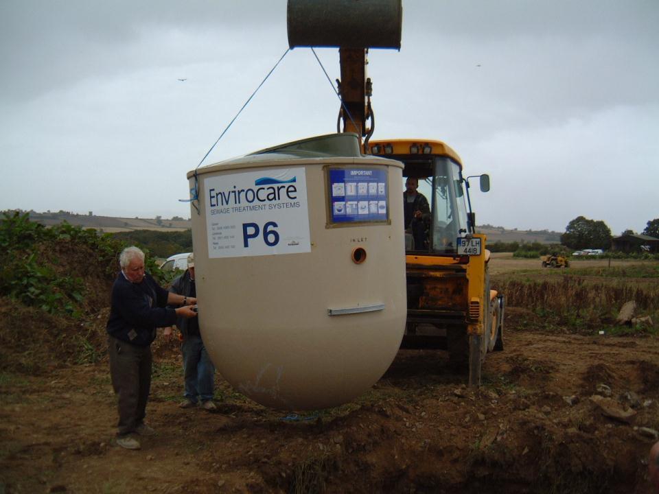
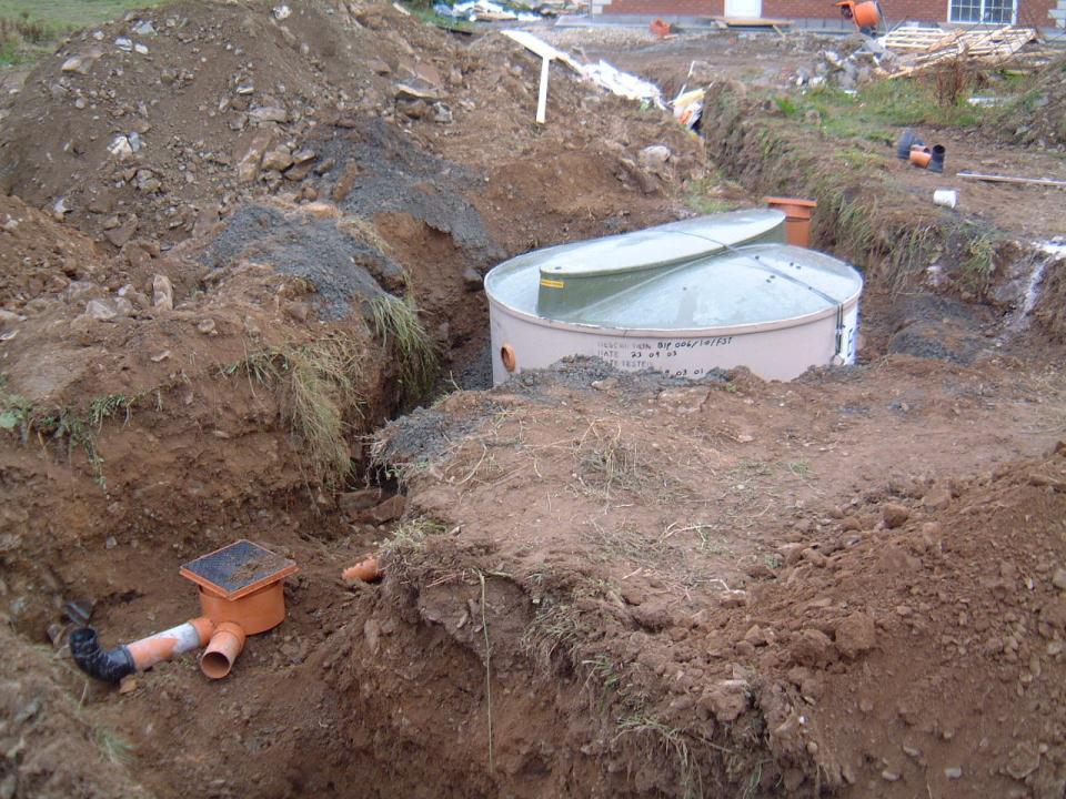
36 * Plastic or fibreglass tanks 36
37 * Mechanical aeration systems are used to treat wastewater from a house where a site is unsuitable for a conventional septic tank system (i.e. failed percolation test). A wide variety of mechanical aeration systems are available. Two such examples are the bio tech from envirocare or biocycle system. 37
38 * This system treats the wastewater in a four stage process: 1. Primary treatment 2. Aeration 3. Clarification 4. Disposal 38

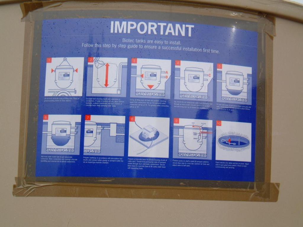
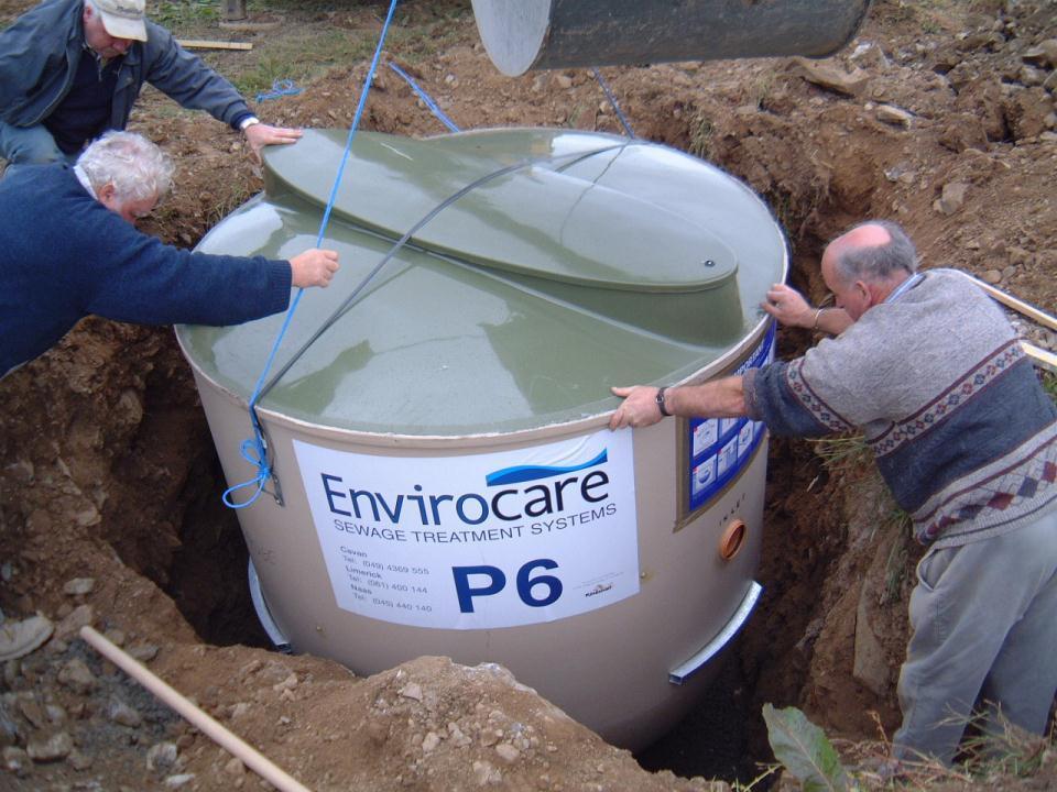
39 Design The entire process takes place in a chamber, which is divided into four different chambers. The wastewater flows by gravity through each chamber in succession. 39
40 Primary chamber Pump chamber Section through tank Outlet Clarification chamber Inlet Aeration chamber m outer diameter tank 0.95m diameter inner tank
41 * In the primary treatment chamber the solids settle and are treated by naturallyoccurring anaerobic bacteria. * Fats and greases rise to the top and form a crust. * The discharge from this chamber flows by gravity into the next chamber (aeration). 41
42 *In the aeration chamber, oxygen is pumped in using a small air pump. This increases the break down of the liquid content almost totally. The discharge from this chamber drains into the clarification chamber. 42
43 *Clarification stage is where the solids settle. The settled solids are returned to the primary treatment stage. 43
44 *The clarified wastewater flows to the sump and from there it is pumped to the percolation area. *Alarms are fitted to alert the home owner if the electricity supply is interrupted or if the air pump or water-pump malfunction. 44
45 45

46 * *Preformed plastic or fibreglass tanks are positioned using a crane or JCB. 46

47 Pipe-work to septic tank 47

48 Access junction at entry of septic tank 48

49 Access junction Hole for septic trank 49

50 Septic tank laid on dry mix of concrete 50
51 51
52 52

53 Access junction at entry of septic tank 53

54 Dry mix of concrete 54

55 Access junction at exit of septic tank 55
56 To percolation area 56
57 * 57
 3.")
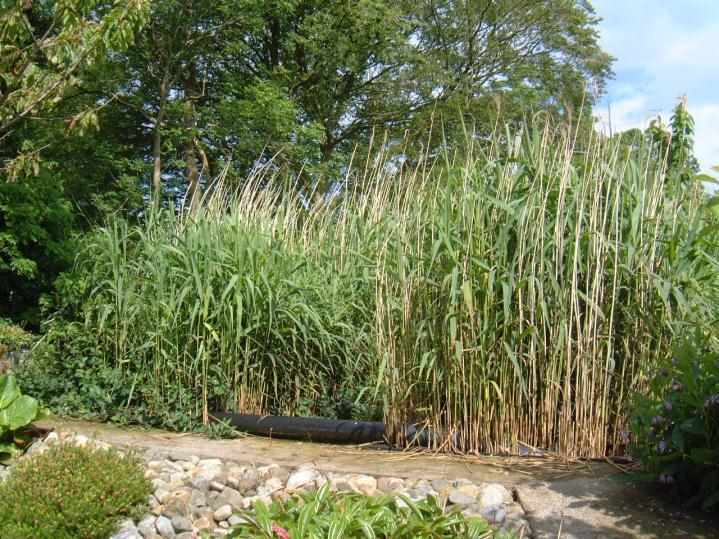
58 * 1. A constructed reed-bed system is another system that will improve the quality of wastewater treatment on a site that is not suitable for a conventional septic tank system. 2. consists of an artificially-created wetland planted with specially selected species of reeds (e.g. Phragmites australis) 3. Reeds have the ability to absorb oxygen from the air and release it through their roots. 4. Allows for aerobic bacteria to break down the contaminants present in the liquid effluent. 58


59 Reed-bed system Septic tank Reed-bed To percolation area or to a pond 59

60 Reed-bed system Wastewater pipe from house 60

61 Reed-bed system Wastewater flows into septic tank. 61

62 Reed-bed system Wastewater flows from septic tank to reed-beds. 62

63 Reed-bed system 63 Wastewater flows into reed-beds

64 Reed-bed system 64 Wastewater flows through a series of pipes with holes.

65 Reed-bed system Special reeds absorb oxygen from the air. This creates ideal conditions for the development of aerobic bacteria which are able to break down the contaminants present in the liquid effluent. 65

66 Reed-bed system Treated water from reed-beds flows into garden pond. 66

67 * Inlet & Outlet pipes inspected every month Percolation area checked for ponding, signs of blocked pipes/odours Vents should be checked every month Sludge levels should checked every 6 months Sludge should be removed once every year 67