DOMINATING PROCESSES DURING DNAPL REMOVAL FROM THE SATURATED ZONE USING THERMAL WELLS
|
|
|
- Aubrey Norman
- 5 years ago
- Views:
Transcription
1 Lecture Session (LeS): E.11 Modelling DOMINATING PROCESSES DURING DNAPL REMOVAL FROM THE SATURATED ZONE USING THERMAL WELLS Uwe Hiester, Martina Müller, Oliver Trötschler, Hans-Peter Koschitzky, VEGAS Research Facility for Subsurface Remediation, Universität Stuttgart, Germany Ralph S. Baker, John LaChance and Gorm Heron, TerraTherm, Inc., Fitchburg, USA Myron Kuhlman, MK Tech Solutions Inc., Houston, Texas, USA Corresponding author: Uwe Hiester, VEGAS, Universität Stuttgart, Pfaffenwaldring 61, Stuttgart, Germany, phone: +49 (0) , Keywords: Contaminated soil, chlorinated solvents, In Situ Thermal Remediation INTRODUCTION Dense Non-Aqueous Phase Liquid (DNAPL) source zones are considered to be among one of the most complex and difficult types of contaminated sites to remediate. To remove the contaminated source zone, conventional clean-up methods like pump and treat often fail due to low mass removal rates and remaining NAPL pools. Soil vapour extraction (SVE), multiphase extraction, in-situ air sparging, chemical oxidation, surfactant flushing and steam-air injection are all challenged by heterogeneity. The heterogeneities are primarily characterized by a large variation of hydraulic conductivity and/or by layers of low permeability within the source volume to be remediated. Since contaminants are entrapped in both high and low permeable layers preferential flow and bypassing of lower permeable zones can leave such residual contamination widely untreated. In-Situ Thermal Remediation (ISTR) technologies include Steam-Enhanced Remediation (SER), Electrical Resistance Heating (ERH) and Thermal Conduction Heating (TCH) are beginning to be widely applied to overcome these limitations. While SER has its greatest applicability to higher permeable zones beneath the water table through which injected steam can flow, ERH and TCH are most often applied within low and moderate permeability zones and in heterogeneous settings. ERH depends on the electrical conductivity of soil, which varies over a factor of several hundreds depending on soil type, from clay to sand. High electrical conductivity is associated with zones that retain water and contain clay minerals. Furthermore ERH is limited to achieving the boiling point of water, similar to SER. By contrast TCH is governed by the thermal conductivity of soil which is one of the most invariant of all soil physical properties varying only by a factor of about three over a wide range of soil types from clay to gravel. Mainly by conductive heating, TCH can heat the subsurface to temperatures below, at or if needed well above the boiling point of water. Additional, density driven warm water flow (only liquid phases) and capillary forces in a heat pipe system (liquid and gaseous phase available) enable a convective heat transport even in low permeable soils [UDELL & FITCH, 1985]. Thus TCH has applications in layers of low permeability, heterogeneous subsurface settings and for contaminants with moderate to high boiling points. Motivation and Scope of Research Work Recognizing the need to gain a better understanding of the underlying mechanisms of TCH/ISTD for treatment of DNAPL in the saturated zone, VEGAS (physical experiments on different scales), MK Tech Solutions (numerical simulations) and TerraTherm (coordinator) formed a research collaboration. This research project was intended to rigorously investigate and help optimise these processes and accompanying contaminant mobilization and removal. The project was funded by the U.S. Strategic Environmental Research and Development Program (SERDP). The results from initially bench-scale two-dimensional (2-D) remediation experiments are subject of a companion paper [BAKER ET AL. 2008]. 2-D experiments had been used to study the principal mechanisms
2 that control the performance of TCH/ISTD below the water table. The results served as a benchmark for the numerical simulations allowing testing of its reliability for representing such processes. The experimental data thus enabled calibration of the numerical model to improve the accuracy of subsequent simulations. The calibrated numerical model was then used to design the more complicated experiments, including 3-D experiments conducted in two large-scale tanks. The objectives of the overall project are: 1) to determine the impact of boundary conditions like soil permeability or groundwater flux on the heated zone, 2) to determine the relative significance of the various contaminant removal mechanisms below the water table (e.g. volatilization, stream stripping), 3) to assess the percentage of the DNAPL source removal and accompanying change in water saturation at various treatment temperatures/durations through boiling; and 4) to evaluate the potential for DNAPL mobilization, either through volatilization and recondensation (gaseous and liquid phase), and/or pool mobilization (only liquid phase) outside of the target treatment zone (TTZ) during heating. SET-UP OF 3-D EXPERIMENTS For the 3D-experiments carried out at VEGAS, two stainless steel tanks with a base of 3 m x 6 m and 6 m x 6 m had been filled with soil each up to a height of 4.5 m (75 m³ and 150 m³). The low permeable layer (height = 1.5 m) in the middle of the tank is surrounded by layers of higher permeability. The set-up of the smaller tank is shown in Figure 1 and tank specific data are summarized for both tanks in Table 1. In both tanks, four (eight) heater wells in a square of 1 m x 1 m had been operated. The groundwater level at the outflow had been operated on a constant head boundary at 3 m above base. The groundwater inflow varied depending on the experimental phase. Each tank had been equipped with Pt100 temperature sensors in 12 layers with 15 to 17 sensors/layer (approx. 200 sensors/tank), respectively. The temperature sensors had been arranged in a V-shape between the inflow and the centre of the container (Figure 1 Top: A-Z in blue colour). Additional, High Temperature and Corrosion resistant Time Domain Reflectory Sensors (HTC-TDR-sensors) were installed to measure the water saturation at the tank centre line (Figure 1: profile A-F in pink colour (left hand side). For the remediation experiments NAPL-pools can be created by injecting a known substance into two NAPL-storage lenses. These lenses were located in the aquitard in a height of m (upper lens) and of m (bottom lens) (Fig. 1, bottom: shaded in red) above base. To monitor a potential contaminant migration during the remediation experiments, sampling ports were integrated in both tanks at 7 different heights with 3 to 25 ports on each level. The initial interest of the research had been focussed on a potential risk of DNAPL-downward migration in the bottom aquifer, where most of the sampling ports were installed.

3 FIGURE 1: Set-up of the smaller 3-D tank. Top: Plan view, bottom: side view. To identify the operation parameter of mayor interest a couple of numerical simulations were performed. The migration of a steam front within the saturated zone is a complex process of single effects like convective spreading in all directions, the heat-pipe effect [UDELL & FITCH, 1985] and a steam override. The results of the numerical simulation showed that two characteristic types of steam front migrations have to be differentiated. In case of a sufficient cooling at the bottom of the aquitard by the groundwater
.")
4 flux in the aquifer, the steam front remains in the aquitard (steam front type 1). In opposite to this low or even no groundwater flux might enable a steam front to migrate into the lower aquifer (steam front type 2). Figure 2 shows schematically the different steam front propagation scenarios. Since the steam front contains high amounts of contaminants and might push recondensed and accumulated liquid contaminants a type-2-front would cause an irreversible transport of contaminants into the aquifer. In relation to the tank set-up a contaminant recovery by SVE would be impossible. FIGURE 2. Schematic steam front propagation due to numerical simulations (side view). To quantify the impact of the groundwater influx on the temperature distribution and steam front propagation one heat transport experiment for each tank was conducted varying the groundwater flux. The thermal wells operated at full power (6kW) and the groundwater outflow was kept constant at 3 m above base. The operational settings are summarized in Table 1. TABLE 1: Summarised Data from both tanks. Large Container Length Width Height 6 m 6 m 4.5 m Small Container 6 m 3 m 4.5 m K S of lower permeable soil layer 1 3 x 10⁻⁶ m/s 1 4 x 10⁻⁷ m/s K S of good permeable soil layers 1 x 10⁻³ m/s 1 x 10⁻⁴ m/s Power of heater 6 kw (4 heater) 6 kw (4 heater) Groundwater outflow (const. head) 3 m above base 3 m above base Phase 1a l / (tank width x day) l / (tank width x day) Phase 1b l / (tank width x day) l / (tank width x day)
 RESULTS The following results focus on the heat transport experiments and the interpretation of the temperature distribution.")

5 Phase 1c 48.3 l / (tank width x day) l / (tank width x day) Phase 1d 1.7 l / (tank width x day) 10 l / (tank width x day) Phase 1e l / (tank width x day) Phase 1f l / (tank width x day) RESULTS The following results focus on the heat transport experiments and the interpretation of the temperature distribution. To interpret the steam front migration data of the temperature measurements are used. FIGURE 3. Temperature development in the central profile j, top: time-variation curve, bottom: spatial interpolation of the measured data The development of the temperatures at the central profile j versus time of the heat transport experiment in the smaller tank is shown in Figure 3 as an example. Both diagrams indicate the same data. However, the lower diagram also shows the spatial interpolation of the temperatures. Focusing on the variation of the groundwater influx during the phases 1a 1f (see Table 1) the experimental settings and the results during the phases 0, 2 and 3 are not discussed in this paper.
6 Independent of the groundwater flux during phase 1 the temperatures reached above 100 C in the upper NAPL storage lens. The steam front exceeded the upper DNAPL storage lens. Thus, no influence of the groundwater influx on the temperatures in the upper part of the aquitard was observed. Opposite to this, the temperatures in the lower NAPL storage lens are dominated by the change of groundwater flux for the present heater configuration. For high groundwater discharges (phase 1e and 1f) temperatures decrease and the steam front collapsed in the lower lens. Numerical simulations indicated a breakthrough of the steam front in the lower aquifer. This was not observed even for no-flow conditions (phase 1d). Dependent on the hydrostatic pressure ρ water g h of the groundwater the pressure for the boiling of water p boiling increases in the saturated zone by depth: p boiling = p + ρ atm water g h with: p boilng = pressure, where water boils p atm = atmospheric pressure ρ water = density of water g = gravity constant h = height of the saturated zone at the evaluated point Therefore the boiling temperature T boiling to steam the water in the saturated zone increases, according to WAGNER [REID ET AL., 1988]: ln p boiling, r aτ + bτ + cτ + dτ = T r with: p boiling,r = p boiling /p c = reduced pressure (pressure, where water boils / pressure at critical point) T r = T boiling /T c reduced temperature (Temperature, where water boils / Temperature at critical point) τ = 1-T r The existence of steam at 1.5 m below the groundwater table (1.5 m above base) is related to a temperature of nearly 104 C. During the heat transport experiment the steady state temperatures at the bottom of the aquitard did not exceed 95 C indicating the lack of steam and the capability to steam water at this depth. Therefore only a one-phase-system warm / hot water system exists at the bottom of the low permeable layer and in the coarse sand aquifer. Nevertheless, steady state temperatures of the warm water correlated well with the specific groundwater flow [m 3 /(tank width*d)] as shown in Figure 4. The data of the central profile j between the heaters of both heat transport experiments are illustrated. For increasing groundwater flux the temperatures decrease due to the increasing energy output of the groundwater. The polynomials correlations between temperatures and groundwater flux (3 rd order for the small tank, 2 nd order for the large tank) show correlation coefficients R² > For higher discharges an asymptotic characteristic of the correlation was found. Due to the limited convective heat transfer coefficient across the boundary of low and high permeable zones the decrease of temperature was slower for a high groundwater flux. At a certain discharge the maximum energy output by the groundwater was achieved. Although the soil permeability varied by one order of magnitude (Table 1) only minor temperature differences could be observed between both tanks within the lower part in the layer of low permeability (Figure 4, height 155 and 190) caused by the conductive dominated heat transport. Within the permeable aquifer (Figure 4, height 140) the advective heat transport dominated and caused higher temperatures. In both structures, aquitard as well as aquifer, higher temperatures were observed in the layers with lower permeability. Here, the advective heat transport is less dominant compared to the conductive transport. Similar correlations have been found for other profiles but the temperatures are not as high as in central profile j.

7 FIGURE 4: Correlation between groundwater flux and steady state temperatures during the experimental phases. Opposite to the bottom of the low permeable layer water was steamed in the middle and at the top of the low permeable layer. Figure 5 shows the steady state steam front extension in the larger (pink lines) and in the smaller (blue lines) tank. Solid lines represent a constant head inflow boundary characterized by a low groundwater flux (below 10 l / (m x d)) whereas dotted lines represent higher discharges (about 333 l / (m x d)). The cooling effect of increasing groundwater flux almost had no impact on the steam front in the middle of the low permeable layer (height 225 cm above base (a.b.)) and only a moderate impact on the steam front extension at the top of the aquitard (height 260 and 295 cm a.b.). In opposite to this the steam front collapsed due to the increased groundwater flux and warm water remained in the center of the low permeable layer about 40 cm above the aquifer (K S2 at height 190 cm a.b.). No significant steam front and steam zone was observed on height 190 cm a.b. for the higher permeable aquitard material K S2.

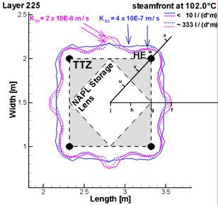


8 Figure 5: Steam front propagation per measurement layer in both tanks (with different permeabilities).
9 CONCLUSIONS AND OUTLOOK An efficient NAPL recovery from the saturated zone by an SVE-system requires a vaporisation of the NAPL and a coherent flow path of the gaseous phase towards the unsaturated zone and the SVE-wells. Following this approach the steaming of the water from the aquitard in the given large physical models is as important as the formation of a steam override zone to enable a migration of gaseous NAPL into the unsaturated zone. The generation of steam is significantly impacted by the soil permeability, the depth below the groundwater level and the cooling effect by the groundwater flux during the experiments. The higher the soil permeability the higher is the cooling effect by the groundwater and thus the lower are the temperatures at steady state conditions. For the given power of the heater wells in a distance of 1 m a high groundwater flux limits the lower expansion of the steamed zone indicating that NAPL located close to the boundary between water saturated aquitard and aquifer may not be recovered. The experimental results indicate the need of an advanced numerical simulation to predict the steam front propagation, the temperature distribution and the recovery of NAPL. The data are currently analysed and compared with advanced numerical simulations. Currently, remediation experiments are under operation. Results from these experiments as well as a comparison of experiments and numerical simulations will be presented during oral presentation. ACKNOWLEDGEMENT This research was supported wholly (or in part) by the U.S. Department of Defense, through the Strategic Environmental Research and Development Program (SERDP). REFERENCES Baker, R.S In Situ Thermal Remediation of Soil Contaminated with Organic Chemicals. Report of the Pilot Study Meeting, Prevention and Remediation in Selected Industrial Sectors: Small Sites in Urban Areas, Athens, Greece, June 5-7, EPA 542-R Presentation available at: Baker, R.S., J.C. LaChance, G. Heron, U. Hiester, H.-P. Koschitzky, O. Trötschler, A. Färber, and M. Kuhlman DNAPL Removal from the Saturated Zone using Thermal Wells. Paper F-34, in: Bruce M. Sass (Conference Chair), Remediation of Chlorinated and Recalcitrant Compounds Proceedings of the Fifth International Conference on Remediation of Chlorinated and Recalcitrant Compounds (Monterey, CA; May 2006). ISBN , published by Battelle Press, Columbus, OH, Hiester U., T. Theurer, A. Winkler, H.-P. Koschitzky and A. Färber Technical Scale Investigations for the In Situ Remediation of Low Volatile Contaminants by Thermal Wells. pp In O.Uhlmann (Ed.), Conference Proceedings: 8th International FZK//TNO Conference on Contaminated Soil (ConSoil 2003) May 2003, Ghent, Belgium. Baker, R. G. Heron, J. LaChance, A. Färber, L. Yang, and U. Hiester D physical models of thermal conduction heating for remediation of DNAPL source zones in aquitards. In Conference Proceedings: 10th International FZK//TNO Conference on Contaminated Soil (ConSoil 2008). 4-6 June, Milan, Italy. LaChance, J., G. Heron and R. Baker Verification of an Improved Approach for Implementing In- Situ Thermal Desorption for the Remediation of Chlorinated Solvents. Paper F-32, in: Bruce M. Sass (Conference Chair), Remediation of Chlorinated and Recalcitrant Compounds Proceedings of the Fifth International Conference on Remediation of Chlorinated and Recalcitrant Compounds (Monterey,
10 CA; May 2006). ISBN , published by Battelle Press, Columbus, OH, Li, J Experimental Investigation on Thermally Induced Buoyancy Flow in Porous Media, Masters Thesis, Universität Stuttgart, Institute of Hydraulic Research, Thesis-supervision Arne M. Färber, Olaf A. Cirpka, Stuttgart, Germany. Li, Y Physical Models for Thermal Remediation of DNAPL Source Zones in Saturated Aquifers. ENWAT Seminar, Feb. 15th 2007, Universität Stuttgart, Institut für Wasserbau, Stuttgart, Germany. Mark, J Permeability and Grain Size Relationships: Designing Specific Soil Properties for Thermal Remediation Experiments, M.S. Thesis, Earth Science Department, Göteborg University, Sweden. Reid, R.C., Prausnitz, J.M., Poling, B.E The Properties of Gases and Liquids. McGraw-Hill Book Company, 4.edition Udell, K.S. and Fitch, J.S Heat and Mass Transfer in Capillary Porous Media Considering Vaporisation, Condensation and Non-Condensible Gas Effects. Paper presented at 23rd ASME/AIChE National Heat Transfer Conference, Denver, CO.