Low Carbon Technology for Marine Application. Hyundai Heavy Industries / Corporate Research Center Se-Young Oh, Sangmin Park Nov.
|
|
|
- Simon Woods
- 5 years ago
- Views:
Transcription


1 Low Carbon Technology for Marine Application Hyundai Heavy Industries / Corporate Research Center Se-Young Oh, Sangmin Park Nov. 29, 2018
2 Contents 1. Background 2. Hydrogen Energy for Marine Application 3. Concept of Cargo Handling System for LH 2 Carrier 4. HHI s R&D Interests
3 Background & HHI s Technologies

4 Background Regulation Area Year Remarks NOx NOx ECA Global TierⅡ TierⅡ TierⅢ IMO MARPOL SOx ECA Sulfur 1.0 % Sulfur 0.1 % IMO SOx MARPOL Global Sulfur 3.5 % Sulfur 0.5 % CO 2 (EEDI*) Global ** EEDI: Energy Efficiency Design Index Phase 0 Phase 1 Phase 2 Apply to ships with dry contracts since 13 IMO MARPOL IMO MEPC 66 decided to apply NOx Tier III regulation to ships that are built since Jan and operated in ECA ( 14.3) TIER 1 (17g/kWh) IMO MEPC 70 decided to use 0.5% Sulfur fuel worldwide from 1 Jan ( 16.10) Sulfur 3.5% CO 2 emission control by ship type and size; EEDI is the mass of CO 2 emitted by ships carrying 1ton of cargo (gco 2 /ton nm) Phase 1 (-10% ) 15~19 TIER 2 (14.4g/kWh) TIER 3 (3.4g/kWh) - 80% in ECA (2016~) 0.5% - 85% in global (2020~) Phase 2 (-20%) Phase 3 (- 30%) 25~ 30 20~ 24 (Applied to newly-built ship over GT 400 ton) - 40% (2030~) CO 2 Free/Zero Emission Ship Table source: KR 4


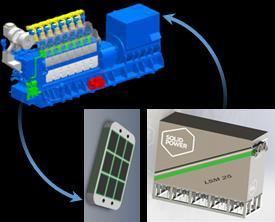
5 Background H 2 World First 2stroke engine Air lubrication system HHI-Scrubber Develop H 2 World First LNG fuel propulsion package demonstration LNG Fuel Propulsion Deliver LNG carrier World largest LNG gas demonstration facility 5


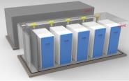
6 Eco Solutions in the Future H 2 1) SOFC : Soil Oxide Fuel Cell 6


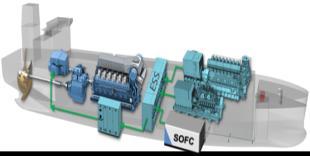
7 Eco Solutions in the Future IMO Strategy on Reduction of GHG Emissions Set-up Strategy for Mid-term Regulation Hybrid w/ Fuel Cell Hydrogen Fuel Standard Hybrid Ship Design - System Optimization & Class AIP - Marine Fuel Cell Integration 7 Multi Fuel Gas Engine - Hydrogen Mixed, High Efficiency DC Power System Design & EMS - System Cost Reduction, Optimal Operation Tech. 1) ESS : Energy Storage System 2) DC : Direct Current 3) EMS : Energy Management System 7


8 Eco Solutions in the Future Carbon Source Carbon Capture Utilization Market insight of hydrogen usage Hydrogen Electric Propulsion System Hydrogen Engine H 2 Hydrogen Carrier Source : McKinsey & Company, Hydrogen Council report - Hydrogen scaling up, 2017 Hydrogen Storage & Distribution 8
9 Hydrogen Energy for Marine Application
, low ignition energy, and high heat conductivity etc.")
10 Hydrogen Energy Clean energy source in the foreseeable future with no GHGs emissions (CO 2, NO x, SO x ) Remarkable technology for eco-ship by liquefied hydrogen storage/transport Consideration of efficiency and safety for LH 2 tank due to diffusion (3 times faster than hydrocarbon in air), low ignition energy, and high heat conductivity etc. LH 2 LNG Boiling point ( o C) Saturated liquid density (kg/m 3 ) Saturated gas density (kg/m 3 ) Fuel CO 2 NOx SOx Diesel 100% 100% 100% LPG 68% 75-80% 3-10% LNG 77% 20% 1% Latent heat (kj/kg) Lower heating value (LHV, MJ/kg) Diffusivity in air (cm 2 /s) Flammability limit (mol%) Hydrogen 0% 0% 0% 10


11 Marine Application of Hydrogen Energy Hydrogen carrier ship Hydrogen-fueled ship Hydrogen carrier ship - Hydrogen engine - Hydrogen + LNG fuel engine - Storage/Transport : Liquefied hydrogen, Organic chemical hydride Hydrogen-fueled ship - Hybrid system : Hydrogen + Fuel cell + ESS Hydrogen carrier ship - BOR handling - Insulation system - Safety issues Hydrogen-fueled ship - High cost (platinum catalyst) - Limit for applying to large ships - Safety issues Stable hydrogen supply Zero-emission fuel ship Low noise and vibration High energy density Efficient hydrogen liquefaction technology 11

12 Hydrogen Infrastructure Technology Hydrogen production from brown coal, biomass, and water etc. Storage by cryogenic liquefaction and high-pressure compression Transport by liquefied hydrogen cargo ships, tanks, and containers Utilization for hydrogen gas turbine/engine, and fuel cell etc. 12
13 Concept of Cargo Handling System for LH 2 Carrier
 AI Alloy steel (MOSS, IHI-SPB) 9% Nickel steel (Type-C & Type-B) Tank geometry Type-C for small ship Type-B for large ship (Developing)")

 Boil-off rate Less than 0.2%/day (Target for 160K Type-B) 0.")

14 Insulation Storage Cargo Tank System LH 2 * LNG Temperature -253 o C -163 o C Tank material Stainless steel AI Alloy steel Stainless steel (GTT Mark III) Invar (GTT NO 96) AI Alloy steel (MOSS, IHI-SPB) 9% Nickel steel (Type-C & Type-B) Tank geometry Type-C for small ship Type-B for large ship (Developing) Membrane type for large ship (Developing) Pressurized tank (Type-C) Nonpressurized tank (MOSS, IHI-SPB) Membrane type (GTT Mark III, GTT No 96) Insulation material Vacuum Insulation Panel Multi Layer Insulation Aerogel etc. (Advanced materials) Block-type PUF (GTT Mark III, Type-B ) Perlite(or Glasswool) Box (GTT NO 96) Expanded Polystyrene (MOSS Type) Spray-type PUF (Type-C) Boil-off rate Less than 0.2%/day (Target for 160K Type-B) 0.085%/day (170K GTT Mark III) LH 2 Storage Tank Structure built by JAXA Tanegashima Space Center (540m 3 ) LH 2 Carrier Conceptual Design Small-scale LH 2 carrier (2.5K) : 2 Tanks (1,250m 3 ), Diesel engine propel (AIP by NK Class, 2014 / Sailing by 2020) Large-scale LH 2 carrier (160K) : 4 Tanks (40,000m 3 ), Hydrogen propulsion (Commercialization by 2025) Study on Introduction of CO 2 Free Energy to Japan with Liquid Hydrogen, Kawasaki Heavy Industries (ICEC25-ICMC2014). 14

 Using only hydrogen as a fuel")

15 Fuel Gas Supply System Cryogenic design and manufacturing technology development for on-board equipment (BOG compressor, cargo pump, fuel supply pump, and spray pump) Using only hydrogen as a fuel Using LNG and hydrogen mixed gases as a fuel - Conceptual design of cargo handling system and FGSS for LH 2 carriers - 15
 - Scenario: vapour diffusion when a rupture of vessel disc - LFL")

16 Safety Standard Estimation of gas dangerous zone in terms of hydrogen flammability Risk assessment using diffusion analysis in vent mast (simulation by DNV Phast TM ) - Scenario: vapour diffusion when a rupture of vessel disc - LFL (Lower Flammable Limit): methane 5%, hydrogen 4% LFL 100% LFL 50 % - Hydrogen LFL distance - - Methane LFL distance - Clarification of Hazardous Areas Applied to Newly Developed Liquefied Hydrogen Carrier, Kawasaki Heavy Industries (ISOPE 2018). 16
17 HHI s R&D Interests

 25~ 29 Applicable: LNG Fuel Prop., WHRU R&D: Hybrid Electric Prop.")
18 Influence of EEDI on Ship Design Development of eco-ship against IMO environment regulation Requirement for all newly built ships over 400 GT from 2013 to meet CO 2 emissions reduction targets Implementation of emission reduction technologies by a shift from low-carbon to de-carbonation shipping EEDI CO 2 Emission Regulation HHI s Technologies Phase I (10% reduction) 15 ~ 19 Phase II (20% reduction) 20 ~ 24 Applicable: LNG Fuel Prop. Ship Phase III (- 30%) 25~ 29 Applicable: LNG Fuel Prop., WHRU R&D: Hybrid Electric Prop., CCS on board 40% reduction, 30 ~ CO 2 Free / Zero Emission Ships Applicable: Hydrogen Prop., CCS on board 18
19 HHI s R&D Interest Feasibility study of installation of hydrogen re-liquefaction system - Economic analysis compared to venting LH 2 BOG - LCA (Life Cycle Assessment) considering voyage distance, speed, and period - Hydrogen Claude Cycle* - * 12 th Cryogenic-IIR Conference; Dresden (2012). 19


20 HHI s R&D Interests Conversion to Fuel On-board CCS Utilization The need for onshore infrastructure Source: DOE/NETL - Conceptual layout of on-board CCS* - * J.T. Van Den Akker, Delft University of Technology,
21 Thank you for your attention