TCP Training. CFB Boiler for TCP, Thailand. General Overview Jyrki Appelgren
|
|
|
- Wilfred Ward
- 5 years ago
- Views:
Transcription
1 CFB Boiler for TCP, Thailand. General Overview Jyrki Appelgren
2 Combustion systems Various solid fuel combustion systems - CFB Boiler introduction

3 The first known boiler

4 Stoker type boilers

5 Pulverized coal combustion PC-boilers
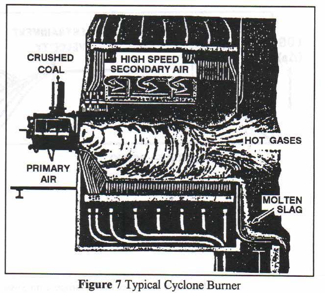
6 Cyclones
7 Fluidized beds

8 Bubbling beds BFB-boilers
9 CFB Boiler Introduction Subject for presentation: CFB Boiler - CFB Boiler process - Fuel selection - Combustion - Emissions - References
10 CFB Boiler Combustion FLUIDIZED BED COMBUSTION Flue gas Flue gas Flue gas Fuel Fuel Air Air Air FIXED BED BUBBLING FLUIDIZED BED CIRCULATING FLUIDIZED BED Intranet/eng/fbt/fbcom.ppt/1100
11 Steam Drum CFB Boiler overview Steam Outlet Steam Water Downcomer Water Wall Water cooled furnace and separator with natural circulation Minimum amount of refractories Fuel Limestone Compact Separator Economizer Air heater Feed Water Inlet Dust Collector Combustion Chamber Fly Ash Intrex superheater Bottom Ash To Ash Silos Primary Air Fan Secondary Air Fan Induced Draft Fan
: Furnace 150 160 W/m2 Separator 25 W/m2 Conv SH 60 W/m2")
12 CFB Hot Loop Gas velocity 24 m/s Gas velocity 38 m/s Gas velocity 5 m/s Thermal heat exchange (very typical): Furnace W/m2 Separator 25 W/m2 Conv SH 60 W/m C
13 CFB Boiler separator overview SOLID SEPARATOR FOR FOSTER WHEELER CFB COMPACT DESIGN FEATURES Square Integrated with furnace No expansion joints Membrane walls Water or steam cooled Normal insulation Mineral wool Refractory ca. 50 mm Membrane wall

14 Power Plant side overview

15 TCP Power Plant side overview

16 TCP CFB Boiler side overview

17 TCP CFB Boiler side overview

18 TCP CFB Boiler side overview
19 CFB Boiler for TCP TCP 35 MWe Coal-Fired Power Plant Performance data at MCR Electric output Steam data Live steam 35 MWe gross, 98 MWt 85 bar, 504 C, +5/-10 C 36,8 kg/s Performance data at 40% load Steam data Live steam 85 bar, 400 C, +5/-10 C 14,7 kg/s
20 CFB Boiler for TCP TCP - Coal-Fired Power Plant Emission data SO2 NOx (calc.as N02) Particulates CO Indoor noise 500 mg/nm3 400 mg/nm3 150 mg/nm3 300 mg/nm3 85 db(a)
21 Emissions in Finland Table 1. Finnish emission limits for solid fuel boilers. Fuel effect SO 2 Peat SO 2 Coal NO 2 Domestic fuel NO 2 Coal Particles Domestic fuel Particles Coal MW th mg/mj mg/mj mg/mj mg/mj Mg/m 3 n mg/m 3 n * 230* ** 25** * 140* * 140* * SO 2 as an year average, NO 2 and particles as maximum ** mg/mj
22 New LPC directive Table 2. New LCP-diretive emission limits for solid fuel boilers. Emission limits are daily averages and will be reported in 6 % of Oxygen content in dry flue gases. Fueleffect SO 2 Biofuel SO 2 Other fuel SO 2 Domestic fuel mg/m 3 n NO 2 Biofuel NO 2 Other wood fuel Mg/m 3 n Particles MW th mg/m 3 n mg/m 3 n mg/m 3 n mg/m 3 n
23 CFB Boiler CFB DEVELOPMENT Fluidized bed technology known in petrochemical and pyrometallurgical industries over 50 years the development of Fluidized Bed Combustion technology started by Ahlstrom Boilers 1st CFB pilot plant 1st commercial CFB Boiler in operation 1st CFB Utility Boiler 110 MWe Pilot plant for Compact CFB Boiler 1st Compact CFB Boiler in operation Foster Wheeler acquired Ahlstrom s Power Boiler Business 185 Foster Wheeler CFB Boilers in operation 24 under construction CFB/CFBdev.dsf/0202/ams
24 FOSTER WHEELER CFB BOILERS Sales and Market Areas Units Units USA China Finland Sweden Germany Japan Poland India Republic of Korea Thailand Czech Republic Austria France Estonia Indonesia Taiwan Norway Switzerland Canada Chile Denmark Israel Italy Spain United Kingdom TOTAL 209 CFB BOILERS cfb/cfbsale.dsf/0202/ams
25 Beyond the entrainment velocity Beyond the entrainment velocity, the particles are carried out of the furnace, and a continuous process is maintained by circulating the same amount of particles to the bottom of the reactor. The entrainment velocity marks the transition from a bubbling bed to a circulating bed. Beyond this velocity, the differential pressure becomes a function of velocity and solid circulating rate.
26 The circulating fluidized bed system operates The circulating fluidized bed system operates in the region between that of a bubbling fluidized bed and that of a circulating fluidized bed until normal bed temperatures are obtained, air flow is above minimum, and the entrainment velocity is reached. From that point the unit operates as a circulating fluidized bed. High turbulence, solids back mixing, and the absence of a defined bed level characterizes this fluidization pattern. The entrained bed material, with an average size in the range of 100 to 300 microns, (talcum powder) is separated by a solid separator and returned to the bed via a non-mechanical seal. Fuel is fed into the lower combustion chamber, and primary air is introduced through a lower grid.
27 Solid fuel combustion In solid fuel combustion the amount of excess limestone feed into the furnace ensures efficient sulfur removal in all conditions, regardless of the amount of sulfur in the fuel, the temperature of the bed, and the physical and chemical characteristics of the brown coal. The ideal reaction temperature range is C. ESB case has two stage sulphur capture: -primary stage in the boiler furnace with limestone injection - secondary stage in the tail-end desulphurization plant
28 FWE s concept for CFB Boiler Membrane wall structure is used for the whole CFB boiler. The Compact separator forms a separate steam cooled circuit and return channel systems together with Intrex-Chambers are integrated with the furnace and connected into the same water circuit. Cooled walls eliminate the need for multi-layer, insulating refractory, which is exposed to high temperature gradients and thus may require maintenance. Thin, single layer of refractory is used in the CFB Compact design only in the locations that may be subject to wear. This refractory on the panel walls is water/steam cooled and the design has been proved in long term operation. The construction enables fast changes in process conditions and reduces limitations related to startup times that are caused by thick refractory. The high quality manufacturing of panel walls is routine work that is carried out at boiler works. The manufacturing of CFB Compact design can be completed in the boiler shop thus reducing the construction time and risks of unexpected delays.
29 FWE s concept for CFB Boiler Solid separator operates as a heat surface and reduces the furnace size. The lower section of the combustion chamber includes a watercooled air distribution grid and a bottom ash removal system. Provisions are made for primary and secondary air supply to the combustion chamber. The primary air is supplied through the lower windbox to the fluidizing grid and provides the initial fluidization airflow. The secondary air provides a staged combustion effect to ensure high combustion efficiencies and to minimize NOx production
30 FWE s concept for CFB Boiler FOSTER WHEELER COMPACT CFB Benefits Less refractory - Availability - Maintenance - Start-up time Cooled panel wall structure - Simple and compact construction - Automated panel welding - Eliminates expansion joints
31 FWE s concept for CFB Boiler LOW EMISSIONS IN CFB No complex external cleaning systems Sulfur dioxide (with limestone injection) - Up to 95 % SO2 reduction lb/mmbtu/25 ppm demonstrated in continuous operation with 0.5 % sulfur coal Nitrogen oxide - Coal typically 0.3 lb/mmbtu/180 ppm without ammonia injection - Coal below 0.1 lb/mmbtu/60 ppm with ammonia injection - Biofuels typically 0.15 lb/mmbtu/60 ppm without ammonia injection
32 cfb/advantag.dsf/0202/ams FWE s concept for CFB Boiler ADVANTAGES OF FOSTER WHEELER CFB BOILER Fuel flexibility Capacity to burn low grade fuels Multifuel burning capability Meets strict emission regulations easily No complex chemical cleaning systems Proven reliability Simple construction
33 cfb/fuelcap.dsf/0202/ams FWE s concept for CFB Boiler CFB TECHNOLOGY OFFERS WIDE FUEL FLEXIBILITY Coal Anthracite Bituminous Sub-Bituminous Lignite Waste Coal Bituminous Gob Anthracite Culm Coal Slurry Petroleum Coke Delayed Fluid Woodwaste Bark Chips Wood Dust Forest Residue Demolition Wood Peat Oil Shale Oil Gas Natural "Off"Gases Sludge Paper Mill De-Inking Municipal Refuse Derived Fuel Paper Waste Tires Agricultural Waste Straw Olive Waste
34 Time The three "T"s of combustion, all necessary for good combustion, are: Time to complete the combustion process; Turbulence Turbulence provides more effective mixing of fuel and air, causes even heat distribution and fills the entire combustor volume; Temperature FWE s concept for CFB Boiler Temperature of the combustor atmosphere must be kept above ignition temperature. Preheating incoming combustion air increases temperature of the furnace atmosphere. Ignition temperatures and combustion temperatures vary with fuel type and preparation.
35 FWE s concept for CFB Boiler Requirements for combustion There are three factors or conditions necessary to produce combustion. These conditions are 1) the presence of a fuel (a combustible material), 2) enough oxygen to support combustion and 3) enough heat to bring the fuel to its ignition temperature and keep it there. These three requirements are all necessary for combustion to occur. If you remove any one, there will no longer be a fire.
36 FWE s concept for CFB Boiler MW e CONVENTIONAL Käyttöönottovuosi
37 CFB DELIVERIES OVER 80 MWe DEL.YEAR CUSTOMER MWe MWth t/h bar C FUELS Tri-State Generation, Nucla, USA KAVO, Kajaani, Finland Vaskiluodon Voima Oy, Seinäjoki, Finland ACE, Trona, USA RWE, Essen, Germany AES-Barbers Point, Hawaiian Island, USA NISCO, Louisiana, USA Nova Scotia Power, Nova Scotia, Canada AES Cedar Bay, Florida, USA Fortum Engineering, Toppila 2, Oulu, Finland Northampton Energy Project, Pennsylvania, USA Colver Power Project, Pennsylvania, USA CMIEC/Neijiang, Neijiang, P.R.C. RAPP,Kerinci, Indonesia x x / / / / / / / / / /32 112/32 128/35 136/29 156/20 174/40 174/ / / / / / / / / Coal Peat, wood, coal Peat, coal Coal Brown coal Coal Petroleum coke Coal Bituminous coal Peat, coal Anthracite culm Anthracite culm Bituminous coal Bark, coal Turow Power Station, Bogatynia, Poland NPS, Tha Toom, Thailand Map Ta Phut, Rayong, Thailand Asia P&P, Dagang, P.R.C. EC Katowice, Katowice, Poland Turow Power Station, Bogatynia, Poland Bay Shore Power Co., Ohio, USA Taiheiyo Cement, Niigata, Japan JEA, Florida, USA Turow Power Station 4-6, Bogatynia, Poland EC Chorzow, Elcho, Poland Zhenhai, Ningbo, P.R.C. 2x235 2x150 2x115 2x x300 3x262 2x113 2x100 2x520 2x370 2x360 2x x689 3x557 2x274 2x / / / / / / / /25 161/ /25 139/31 170/ / / / / / / / / Polish brown coal Anthracite, bit. coal Coal Coal, sludge Coal Polish brown coal Petroleum coke Coal, pet. coke, RDF Pet. coke, bit. coal Polish brown coal, lignite Bituminous coal Bit. coal, pet. coke 2003, 2004 AS Narva Elekrtrijaamad, Narva, Estonia 4x100 4x / /27 540/540 Oil shale bolist/cfb/del80mw.dsf/0202/ams