Cycle Isolation Prioritization and Organization
|
|
|
- Aldous Eugene Young
- 5 years ago
- Views:
Transcription
1 Cycle Isolation Prioritization and Organization True North Consulting Richard Duggan Greg Alder ValvTechnologies Michael Flaherty ValvTechnologies International Technical Conference Oct 6-7, Houston, Texas
2 Agenda Introduction Prioritization Value of leaking valves Organization Process for developing a Cycle Isolation Program Case study


3 True North Consulting Power Services Plant Thermal Performance Engineering Programs Engineering Support Services Software Solutions
4 True North Thermal Performance What do we do? Testing Services Turbine Testing Cooling Tower Testing Feed water heater testing PTC- 46 turnkey testing PTC 6 Testing Heat Exchanger Testing Customized Software TSM Thermal System Monitor CIM Cycle Isolation Monitor TP-Steam Steam Tables Thermal Power Monitor Plant Analysis Turbine Retrofit Evaluations Plant Uprate Evaluations Thermal Performance Program Assessment
5 Introduction Generating plants often suffer from power losses due to leakages through valves that are faulty and/or do not seat correctly. Often these losses are significant and have been difficult to quantify. Leakage Flow High Pressure/High Temperature Leaking Valve Condenser
6 Introduction All organizations have finite resources and need to apply those resources intelligently to get the most out of them. All power Benefit ($) plants have leaking valves, but there may not always be a business case for repairing them.


7 Cycle Isolation Monitoring Monitor high energy valve leakage High energy valve leakage leads to: Increased heat rate Reduced plant efficiency Potential valve damage LOST MW!
8 Cost of a Leaking Valve How Much is 1 MW of electricity worth? Revenue If the plant CAN t make it, they can t sell it $400,000 per year (Fossil) Fuel Cost? If the plant CAN make it, they need to overcome the loss $250,000 per year, depending on fuel type and efficiency
9 Cost of a Leaking Valve $400,000 $350,000 $300,000 1 MW lost $250,000 $200,000 $150,000 $100,000 $50,000 $ Months with leak in place Total Additional Fuel Cost Lost Revenue Data Source: US Energy Information Administration
10 Cost of Leaking Valves Typically plants have between 2-6 MW of lost generation from leaking valves For a plant that can not make up this loss, this represents $800,000 - $2,400,000 annual lost revenue. For a plant that can make it up, it represents additional fuel costs of $500,000-$1,500,000 + Additional Costs
11 Relative Impact of Leaks Around the Power Plant H SUPERHEATER I A C TURBINE/GENERATOR EFF = 90% POWER OUT REHEATER B HEAT IN EFF = 85% ECONOMIZER G D HEAT REJECTED F CONDENSER FEED PUMP EFF = 90% E
12 Relative Impact of Leaks Around the Power Plant Location of Leakage in Cycle Heat Rate Impact Throttle 0.83% HP Turbine Exhaust 0.53% Ahead of Intercept Valve 0.69% Cross-Over 0.44% Source: Evaluating Steam Turbine Performance by K.C. Cotton
13 Causes of Leakage Leakage due to tank level control problems Leakage due to AOV valve setting issues Leakage due to MOV thermal expansion Relief valve drifting Steam cutting of valves Improper valve alignment Leakage resulting from maintenance on the system Leakage due to foreign material in the valve Leakage from startup valves being left open
14 Prioritization of Leakage Valve leakage should be frequently identified and tracked Prioritization basis Energy level of liquid or vapor upstream of the valve Thermodynamic Impact on cycle Extent of the valve leakage Large valves are expensive to repair so make sure the benefit is there Also include additional checks that confirm the valve is leaking One thing to remember - the size of the leak today will not be the size of the leak tomorrow
15 Prioritization of Leakage-Determining Effect on the Cycle Build a thermodynamic model of the cycle. Most plants already have this. Run the model at normal conditions and record the generation Simulate the leak by pulling a small amount of flow (1%) to the sink Run the model with the simulated leak and record the generation with the leak active.
16 Prioritization of Leakage-Determining Effect on the Cycle Calculate the power in the leaking fluid P = m& h = flow enthalpy Divide the lost generation by the power from the leak LossFactor = P P GenerationLoss LeakageLoss Use this loss factor to determine effect on electric generation from each leak
17 Process for Implementing Cycle Isolation Program
18 Identify Valves to Monitor Review Plant Information Thermal Kits Thermodynamic Models P&ID s Isometrics Normally Closed valves that if open, dump high energy fluid to a sink (condenser, blowdown tank, etc.)
19 What Valves Should Be Monitored? Feedwater heater dump valves Main steam line drain valves Gland seal unloader valve Turbine bypass valves Feedwater heater vent valves Gland steam isolation valves Extraction steam line drain valves Heater bypass valves Feed pump recirc valves Before and after seat drain valves Steam drain line orifices (and orifice bypass valves)
20 Identifying Valves Combined Cycle HP Governor Valve Seat Drain
21 Identifying Valves Coal Cogeneration Plant Feedwater Heater Drain and Vent P&ID
22 Identifying Valves Coal Cogeneration Plant Boiler Blowdown System
23 Walkdown the Unit Verify Location of Valves Determine measurement locations Verify piping configurations Establish the walkdown order Document, document, document Record initial temperature measurements
24 Measurement Locations Pipe surface temperature Condenser Measure temperature approximately 10 diameters downstream of the of the valve. Be careful of conduction across the valve and piping. If using infrared ensure it will be in the line of site from a safe location, but getting the device as close as possible to the pipe. Make sure the pipe is not shiny and that the hole in the insulation is adequate. Know the drawings; look for other paths that could be a source of heat into the location you are measuring.
25 Walkdown the Unit Verify Location of Valves Determine measurement locations Approximately 10 diameters downstream of valve Measure pipe temperature, not insulation temperature Measure distance to sink Verify piping configurations Look for sources of error Environmental conditions Other heat sources Establish the walkdown order Document, document, document Record initial temperature measurements
26 Update List of Valves Collect data on valves discovered during walkdown Update valve information Upstream conditions Valve type, size Pipe size, schedule Distance to condenser Record initial temperatures
27 Determine if Valve Is Leaking Determine nominal temperatures for non-leaking valves Establish threshold for identifying leaking valve What temperature is indicative of a leak? Avoid false positives Verify leakage with alternate source (Acoustic) Calculate Leakage Infer pressure inside pipe from temperature Use piping configuration and sink conditions to calculate flow Calculate value of fluid (high energy, high value) Convert flow to generation or heat rate loss.
28 Prioritize If more than 1 valve is leaking, determine which valve is worth more Effect on lost generation Cost to repair Communicate with maintenance and/or operators to repair/replace valves Isolate if possible Large valves are expensive to repair so make sure the benefit is there Also include additional checks that confirm the valve is leaking One thing to remember - the size of the leak today will not be the size of the leak tomorrow

29 Collect Valve Information Data for each valve is entered into input forms or can be imported from spreadsheets which then produce results from advanced cycle isolation loss calculations which can be graphed and reported to monitor valve degradation over time. The goal of a cycle isolation program is to provide the ability for plant personnel to quickly detect and quantify leakage losses in a plant cycle.
30 Plant Implementation Presentation made at EPRI Heatrate Conference 2009 Interest expressed Implemented on two 300 MW units Unit #6: 304MW CE, 1814psia/1000F Reheat unit tangential twin furnace Unit #1: 300MW B&W, 1812psia/1000F Reheat unit front and back wall fired


31 Plant Implementation Identify valves P&IDs Locate valves walkdown of unit Quality of fluids Thermodynamic models


32 Plant Implementation Site Visit Located all valves Determined proper measurement locations


33 Plant Implementation Site Visit Located all valves Determined proper measurement locations Drilled holes in insulation


34 Plant Implementation Site Visit Located all valves Determined proper measurement locations Drilled holes in insulation Measured upstream and downstream temps

35 Plant Implementation Determined final walkdown order & created Worksheet

36 Valve information sheet Plant Implementation

37 Plant Implementation Entered walkdown results Planned maintenance on valves Estimated savings: 50.3 Btu/kWh $475,000 per year
 Estimated Savings")
38 Post-Overhaul Results Plant Implementation Valve Leakage Summary Closed manual blocking valve (temp now 50 deg F) Estimated Savings $275,000
39 Plant Walkdowns Plant personnel take downstream measurements of temperatures using handheld equipment. Some plants install thermocouples to record temperature measurements. Some plants verify temperature measurement with acoustic methods. Each measurement is recorded using Walkdown Worksheet forms or can be uploaded from spreadsheets or handheld recording devices.
40 Verify Repairs Always measure temperatures before and after repairs to ensure valve is repaired properly Continue monitoring and ensure leaking condition does not return Identify problem locations Document, document, document What repair was performed? When was it performed? Pictures of damage

41 Trending of Leakage
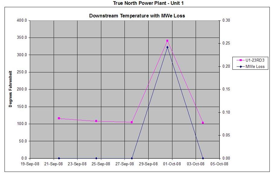
42 Graphing

43 Action Taken Reports

44 Combination of Technology A leak in one valve will increase the pressure in the entire header Acoustics can help pinpoint the leak source
45 Conclusion Prioritize valve leakages Program to structure leakage measurement Identification of leaking valves can happen very quickly Always use good engineering practices and judgment including diverse measurement methods Tracking of leaking valves can be very rewarding Estimate flow losses to cycle Estimate lost generation and heat rate impact