New Erosion and Sediment Control Guidance for the Greater Golden Horseshoe Area
|
|
|
- Judith Daniels
- 5 years ago
- Views:
Transcription

1


2 New Erosion and Sediment Control Guidance for the Greater Golden Horseshoe Area Presented by: Lisa Rocha The water component of STEP is a partnership between:
3 ESC Guideline Update Why is the update needed? GGHA Conservation Authorities ESC Guideline for Urban Construction published over 10 years ago ESC knowledge has expanded & practice has evolved Key changes this past decade: Availability of professional training Legislative changes Changes to BMPs Expanded knowledge and understanding of key ESC issues Turbidity monitoring requirements for SAR habitat (e.g. Silt Smart Protocol)
4 Authors: TRCA and CVC staff in planning ecology, water resources engineering, STEP, and restoration services. External advisory group including representatives from: Provincial ministries (MOECC, MNRF, MTO) Environment Canada Municipalities Construction and development industry (i.e. consultants, developers, contractors) Ten conservation authorities in southern Ontario (TRCA, CVC, GRCA, LSRCA, CLOCA, UTCA, RVCA, HRCA, HCA, NVCA)

5 Highlights Qualitative erosion risk assessment methodology Updated information on protecting natural features during in-water works Guidance on ESC effectiveness and turbidity monitoring Recommendations for protecting LID features during construction Clarification of approvals process, including flowcharts Inclusion of new BMPs and adoption of generic BMP names


6 Primary Sources Guide draws on information from several key locally applicable guidelines, standards and policies Additional sources: Federal and provincial legislation Research papers and studies ESC guidance from other jurisdictions in Canada and the U.S.
 and RUSLE For Application in Canada (2002).")
7 Erosion Risk Assessment New addition to the guide Derived from MTO s risk assessment methodology outlined in Environmental Guide for ESC During Construction of Highway Projects (2015) and RUSLE For Application in Canada (2002). Part of preliminary site assessment done prior to the start of construction
8 Erosion Risk Assessment Qualitative assessment of erosion risk based on the following factors: Soil Characteristics Topography Rainfall and Climate Variations Soil Cover Duration and Extent of Disturbance Larger development sites divided into polygons of like erosion potential Erosion risk assessment is carried out for each polygon Outcome of erosion risk assessment informs decisions about appropriate BMP selection
 Requires onsite investigation and desktop analysis STEP 2: Divide site into polygons (for larger sites) Areas of like erosion risk Based on site data collected and use of GIS See")
9 Erosion Risk Assessment STEP 1: Collect site information Data related to erosion risk (e.g. soil type, slopes) Requires onsite investigation and desktop analysis STEP 2: Divide site into polygons (for larger sites) Areas of like erosion risk Based on site data collected and use of GIS See MTO guideline for examples Photo credit: MTO s Environmental Guide for ESC during the Construction of Hwy Projects (2015) STEP 3: Rate erosion risk for all factors Use tables provided to classify erosion risk as low, moderate or high Repeat for each polygon
10 Erosion Risk Assessment Soil Characteristics Soil Type Erodibility Classification Soil Erodibility Rating Well Graded Gravel Least Low Poorly Graded Gravel Low Sand Low Loamy Sand Low Heavy Clay Low Clay Low Silty Clay Low Silty Clay Moderate Sandy Clay Loam Moderate Silty Clay Loam Moderate Sandy Loam Moderate Silty Sand High Loam High Silt Loam High Silt Most High 10
11 Erosion Risk Assessment Topography Slope gradient Soil erodibility Erosion Potential slope length <30 m slope length >30m Low Low Moderate <2% Moderate Moderate Moderate High Moderate High Low Low Moderate 2-10 % Moderate Moderate High High High High Low Low Moderate >10% Moderate High High High High High 11


 following topsoil stripping and/or")
12 Erosion Risk Assessment Soil Cover Cover Management Erodibility Classification Soil Erodibility Rating Densely vegetated areas Least Low Sodded/Established Vegetated Areas Soil Sealant and Rolled Erosion Controls Hydroseeded/Hydromulch Areas Prior to Significant Vegetation Growth Established temporary crop covered/vegetated lands Seeded lands prior to significant vegetation growth Sparsely vegetated lands Low Moderate to Low Moderate to Low Moderate High High Bare lands (exposed soil) following topsoil stripping and/or grading Most High 12
13 Erosion Risk Assessment STEP 4: Determine overall erosion risk for each polygon Use table provided to assign values according to the risk level for each factor Total points to determine if erosion risk is low, moderate or high STEP 5: Apply overall erosion risk assessment to determine best practices Use table provided to consider which structural and non structural best practices are appropriate in each polygon
14 Erosion Risk Assessment Overall risk determination (in each polygon) Erosion Risk Factors Low Moderate High Soil Characteristics Soil Cover Extent of Disturbance Topography Values weighted based on relative importance of each risk factor Duration of Disturbance Rainfall and Climate OVERALL EROSION RISK Low Moderate High Range of values based on totals above
15 Applying the erosion risk assessment Minimum best practices recommended Low risk Moderate risk high risk Procedural ESC Measures yes yes yes ESC Plan yes yes yes Routine inspection of ESC effectiveness yes yes yes Flow/Runoff Diversion optional where possible yes Staged Construction and Progressive Rehabilitation optional where possible yes More intensive ESC measures optional optional Yes Turbidity monitoring optional After significant rainfall/snowmelt Continuous
16 The turbidity monitoring spectrum Method Location Advantages Handheld turbidity measurement of grab samples Site discharge points Receiving water D/s and U/s of site Straightforward Low equipment cost Direct measurement of site runoff = greater accountability Problem areas can be pinpointed Can be carried out even in the winter Low equipment cost More readily comparable to existing CWQG for aquatic life Can be carried out even in the winter Continuous online turbidity measurement Outlet of sediment control pond Receiving water D/s and U/s of site Concentration & duration = more accurate assessment Convenience - data logged at all times of day and night Set location means higher precision and comparability Concentration & duration = more accurate assessment Convenience - data logged at all times of day and night Set location means higher precision and comparability Readily comparable to existing CWQG for aquatic life Continuous online turbidity measurement with remote real-time access to data Outlet of sediment control pond Receiving water D/s and U/s of site In addition to those listed above: Convenience of remote access Opportunity for faster problem response In addition to those listed above: Convenience of remote access Opportunity for faster problem response
17 The turbidity monitoring spectrum Method Location Disadvantages Handheld turbidity measurement of grab samples Continuous online turbidity measurement Continuous online turbidity measurement with remote real-time access to data Site discharge points Receiving water D/s and U/s of site Outlet of sediment control pond Receiving water D/s and U/s of site Outlet of sediment control pond Receiving water D/s and U/s of site Staff costs for sampling Limited to locations where grab sampling is possible Potential for error due to poor sampling technique Duration is not assessed Need to determine pre-construction background turbidity Staff cost for pre-and during construction sampling Higher equipment cost Staff costs for data QA/QC Site visits required to retrieve data delays problem response Only pond effluent is assessed Not operational during winter Higher equipment cost Staff costs for data QA/QC Site visits required to retrieve data delays problem response Need to determine pre-construction background turbidity Staff cost for pre-and during construction sampling Not operational during winter Highest equipment cost Staff costs for data QA/QC Only pond effluent is assessed Not operational during winter Highest equipment cost Staff costs for data QA/QC Need to determine pre-construction background turbidity Staff cost for pre-construction sampling Not operational during winter


18 Turbidity monitoring in the Silt Smart Protocol Silt Smart - Erosion and Sediment Control Effectiveness Monitoring and Rapid Response Protocol for High Risk Construction Projects Requirement for continuous in-stream turbidity monitoring with remote real-time data access Eligible sites are: >25 ha and/or high risk; and Discharging to sensitive streams including those that support species at risk and coldwater species
19 Turbidity monitoring in the Silt Smart Protocol Trigger levels are determined for each site based on pre-development background turbidity The configuration of the equipment allows contact groups to receive alerts when turbidity exceeds triggers. Protocol focuses on prevention, encouraging rapid response to ESC deficiencies on high risk projects Response and reporting requirements: Requirement Problem response Details All deficiencies in ESC design and maintenance as identified through inspection will be rectified as soon as possible and not later than 24 hours of notice. Preliminary assessment report Required within 10 hours after first light Final assessment report Report, stamped by a qualified professional, is required within 48 hours of the end of the occurrence.

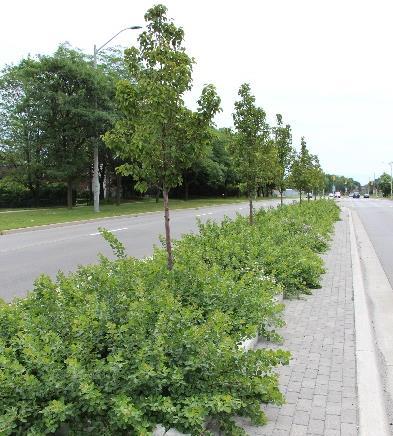


20 Protecting LID during construction What types of LID need protection during construction? Practices applied at or below ground level to infiltrate or filter stormwater
 Subgrade compaction by heavy machinery Contamination by")

21 Protecting LID during construction Impacts to LID during construction, where inadequate protection is in place: Clogging with sediment Erosion of inlets and beds (for planted areas) Subgrade compaction by heavy machinery Contamination by substances in construction runoff Lack of understanding of the system can also result in damage to components Protection required until: construction is complete contributing drainage area is stabilized construction vehicle mud tracking has ceased
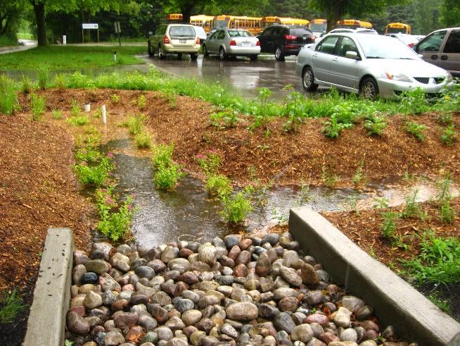
22 Protecting LID during construction Diverting flows around LID areas provides best protection Benefits: Less erosion risk, clogging Opportunity for seeded/planted LID areas to become established Easier access to carry out additional construction, repairs or maintenance of the LID area
 or sand ( 5 cm) and geotextile is added on top of the final post construction grade of")

23 Protecting surface infiltration LIDs When flows can be diverted LID is built but not planted A layer of growing media ( 10 cm) or sand ( 5 cm) and geotextile is added on top of the final post construction grade of the BMP This sacrificial protective layer is removed once construction is complete and BMP starts receiving flow Enhanced protection - compost biofilter socks surrounding the area and stabilization of the sand/growing media


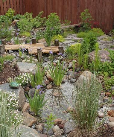
24 Protecting surface infiltration LIDs When LID area serves as temporary detention basin When flows cannot be routed around LID during construction Bioretention example shown Retain 75 cm native soil between the base of the detention basin and the final base of the LID when complete. Sediment accumulation in detention basin removed during excavation to construct LID. Once LID is built, protect until construction and stabilization are complete.


25 Protecting surface filtration LIDs When LID area serves as temporary detention basin When flows cannot be routed around LID during construction Grass swale example shown Retain 30 cm native soil between the base of the detention basin and the final base of the LID when complete. Once LID is built, protect until construction and stabilization are complete.
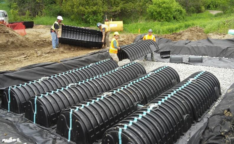
26 Protecting LID during construction LID installations that are below ground (e.g. infiltration chambers), can be constructed early (e.g. during cut/fill) Barrier (e.g. plug, bulkhead) must be installed during construction to prevent facility clogging Facility only begins to receive runoff when construction is complete, drainage area stabilized, vehicle mud tracking has ceased.

27 Protecting LID during construction General guidance Ensure LID areas are properly identified and sectioned off, and that staff are aware of best practices Maintain LID perimeter controls throughout construction Avoid heavy equipment on intended infiltration sites to avoid native soil compaction Regular ESC site inspections to include LID areas For detailed guidance CVC s LID Construction Guide (2012) and full day course (
28 THANK YOU! Have any burning questions? Want to get involved? Contact: Lisa Rocha Toronto and Region Conservation ext Project updates and information on other STEP ESC research and training:
29