A turbine based domestic micro ORC system
|
|
|
- Ross Tyler
- 5 years ago
- Views:
Transcription
1 A turbine based domestic micro ORC system Piotr Klonowicz, Łukasz Witanowski, Łukasz Jędrzejewski, Tomasz Suchocki, Piotr Lampart The Szewalski Institute of Fluid-Flow Machinery Polish Academy of Sciences Turbine Department
2 Introduction Nowadays, the world needs more responsible ways of energy conversion and use, Lots of households use solid fuel boilers for heating, A high quality fuel is used to rise the temperature only by a few degrees, The reason: cogeneration in the range up to 20 kw is technologically and economically challenging, MicroCHP technologies for solid fuels: Stirling engines, Peltier modules, Steam systems, ORC systems, Other.
3 Solutions of ORC based systems Coupling an ORC to a typical domestic boiler, low temperature (90 C) > poor efficiency, Pressurized water loop -> high pressures, Thermal oil loop -> relatively expensive, Direct evaporation -> dangerous (potential explosions), risk of working fluid decomposition.
4 Domestic ORC system layout ORC schematic Indirect evaporation Direct evaporation T-s diagram Condensing Introducing a regenerator is an option Many fluids possible Expansion unit is a challenge
5 Results examples for a 15 kw boiler Assumtions: Expander efficiency (including electric generator): 55 % Pump efficiency: 40 % Evaporation temperature: 150 C Cooling water temperature: 15 C Warm water temperature: above 40 C Fluid Condensing Turbine power [kw] Pump power [kw] Net efficiency [%] mass flow [kg/s] p ev [bar(a)] p cond [bar(a)] Cyclopentane Above atmospheric Acetone pressure HFE Cyclohexane Below atmospheric MM pressure HFE
6 Most important turbine design features Fluid N S 30 krpm N S 60 krpm N S 100 krpm N S 150 krpm N S 200 krpm n opt [krpm] u impulse [m/s] u reaction [m/s] A 1x [mm 2 ] Cyclopentane Acetone HFE Cyclohexane MM HFE Where: N S specific speed n opt approximate optimal rotational speed u impulse rotor peripheral speed in a single stage impulse turbine u reaction rotor peripheral speed in a single stage reaction turbine A 1x total area of nozzle critical section
7 Single stage impulse turbines Advantages: Simple design, Low axial thrust, Can be relatively efficient even at low specific speeds (partial admission possible). Disadvantages: Worse efficiency than reaction stages, Worse off-design performance than multistage designs,
8 Impulse turbines performance and features (correlation based)
9 Examples for 100 krpm limit (high condensing pressure) Cyclopentane η = 67% n = 100 krpm ε = 33% Acetone η = 65% n = 100 krpm ε = 29% HFE7100 η = 78.2% n = 75 krpm ε = 100%
10 Examples for 100 krpm limit (low condensing pressure) Cyclohexane η = 74.4% n = 100 krpm ε = 61% MM η = 80.1% n = 72 krpm ε = 100% HFE7100 η = 78.6% n = 73 krpm ε = 100%
11 Case study acetone turbine off-design performance (constant back pressure)


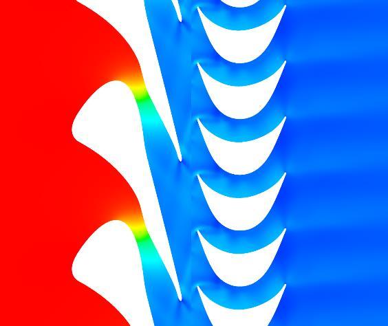
12 Case study acetone turbine blade geometry and CFD

13 Case study 3 kw HFE7100 turbine influence of tip clearance on optimal admission Tip clearance [mm] Admission size [-]

14 Acetone η = 84.2% n = 243 krpm Reaction (radial inflow) turbine example
15 Conclusions It is feasible to design turbines for very small power that achieve acceptable efficiencies, Single stage impulse turbines are a simple and attractive option, Reaction turbines are more efficient but more difficult to build, The sizes, efficiencies, peripheral speeds and rotational speeds vary strongly with respect to different working fluids.
16 Acknowledgements This work has been founded by The Polish Agency for Enterprise Development and from The Smart Growth Operational Programme (European funds) within the project No. POIR /15 carried out jointly with the SARK Company. Calculations were carried using the resources of the Academic Computer Centre in Gdańsk