PRESENTED BY: R MADHUSUDHAN RAO THE SOLUTION THE PROBLEM DEPLETING RESOURCES SOLAR ENERGY TECHNOLOGY INCREASING PRICES INCREASING DEMAND
|
|
|
- Katrina Wheeler
- 5 years ago
- Views:
Transcription


1 CLEANTECH HEATING & COOLING PRESENTED BY: R MADHUSUDHAN RAO APPLICATION - HEATING THE PROBLEM THE SOLUTION APPLICATION - HEATING DEPLETING RESOURCES FUEL SOURCES USED SOLAR ENERGY TECHNOLOGY COAL OIL GAS INCREASING PRICES STEAM GENERATION DRYING HEAT RECOVERY APPLICATION cooling - COOLING APPLICATION - COOLING INCREASING DEMAND Electricity ENERGY EFFICIENT TECHNOLOGY ELECTRICITY IS USED INCREASING GREENHOUSE GAS EMISSIONS ADSORPTION COOLING RADIANT COOLING 1


2 RECOGNITION Climate Solver 2015 Award WWF Skoch Smart Technology Award At COP, Bonn, Germany Global Cleantech Innovation Program CLEANTECH HEATING SOLAR THERMAL WASTE HEAT RECOVERY 2


3 SOLAR THERMAL APPLICATIONS BOILER FEEDWATER PRE-HEATING Solar water heaters enhanced with reflecting glass and indirect heating of feedwater. 3


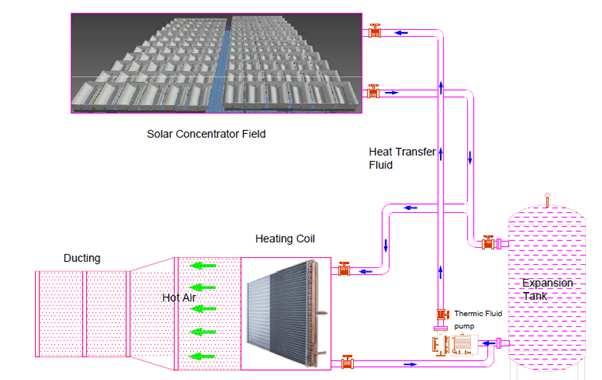
4 SOLAR STEAM GENERATION Steam generation with accumulator for cooking. SOLAR STEAM GENERATION 72 sq.m Parabolic Trough for high temperature upto 300 deg C. 4
5 COMPOUND PARABOLIC COLLECTOR Applications: Solar Hot water system Solar Boiler feed water Temperature upto 120 Deg C. SOLAR STEAM GENERATION 72 sq.m Parabolic Trough for high temperature upto 300 deg C. 5

6 Metal Industry Metal Industry 6


7 SOLAR THERMAL DESALINATION Hot water generated through solar field is used with Multi Effect Distillation system. CPC WITH DUST COVER This product was designed to protect the collector from gathering dust and provide for waterless automated cleaning. 7


8 SOLAR SLUDGE DRYING Open pits Effective drying using Green house SLUDGE DRYING 8


9 SOLAR SLUDGE DRYING SCHEMATIC: Solar (CPC) integrated HELIOSTATS (Hydrogen Generation): Reaction temperature 1200 deg C 9


10 WHR IN CEMENT PLANTS 19 WASTE HEAT RECOVERY Typical Rotary Kiln surface temperature in a cement industry varies from 150 deg C to 400 deg C. Similarly, lime kilns in Paper & Pulp industries too have kiln surface temperature at an average of 200 deg C. There is a continuous loss of heat from such kilns to the ambient


11 HEAT RECOVERY PANELS The proposed apparatus will have heat recovery panels around the kiln. The panels will be mostly placed towards the firing end of the kiln where the temperature is closer to 300 deg C. The heat recovery panels will be at lower temperature due to water circulating in the copper pipes embedded in the panels. Typical inlet temperature will be from deg C and outlet will be deg C for boiler feedwater application and upto 110 deg C for power generation option. Radiative heat transfer will happen from the kiln surface to the panel surface due to the difference in their surface temperatures. These panels will be insulated with rockwool on the back side to avoid heat losses A closer visual of the heat recovery aluminum panels with copper pipes is shown here (without insulation). 21 PILOT STUDY Temperature Profiles from Pilot Study Inlet Temp (Deg C) Outlet Temp (Deg C) Surface Temp (Deg C) Heat Recovery (KW) For an average kiln surface temperature of 240 deg C, a heat recovery rate of 4 KW/sqm was recorded during the pilot. This translates to 82,500 Kcal/sqm/day or approx. 29 million Kcal/sqm/year. This translates to savings of 7.2 Tonnes of coal per year/sqm which costs approx. Rs. 30,000. Different conditions like kiln shutdown, rains etc. might effect the final savings from the heat recovery. 22 The panels require cleaning once a month. 11
12 APPLICATIONS OF WHR Kiln Waste Heat Recovery ( deg C) Power Generation Using ORC Turbine Boiler Feedwater Preheating for Captive Power Plant VAM based Cooling Drying of Limestone, Lignite, Coal 23 CLEANTECH COOLING STRUCTURE COOLING RADIANT COOLING GEOTHERMAL COOLING 12


13 STRUCTURAL HEAT Buildings absorb heat all day long and retain that heat even during non solar hours. Heat retained by the structure is reradiated into the occupied space causing discomfort. Structure Cooling drains the heat trapped in the building thermal mass to cool the building. CEILING SURFACE TEMPERATURE Space surface of a house ceiling at 8 PM in the night when outside temperature is 25 deg C in summer. Heat accumulated by the building structure reradiates to the space. In summer, the building retains the heat in its thermal mass 13


14 STRUCTURE COOLING Embedded pipes flush the heat stored in the building thermal mass COOLING TOWER w/radiant COOLING Electricity Consumed by Structure Cooling: 0.03 KW/Ton Electricity Consumed by Split Acs: 1.2 KW/Ton >95% reduction in power consumption 14
 or Heating uses CONVECTION by using AIR to remove or add heat to a space.")
15 HEAT TRANSFER Working Principle Body at a higher temperature radiates heat to body at a lower temperature. Conventional Cooling (air conditioning) or Heating uses CONVECTION by using AIR to remove or add heat to a space. Radiant Cooling or Heating does not use air, but uses COOLED or HEATED SURFACES to provide cooling or heating a space. WATER SUPPLY TEMPERATURE It can be seen from the above graph that even with supply water temperatures above 20 deg C, the space temperature is being maintained between deg C. We can also use water at deg C to flush out the heat in the building as all heat trapped in the building is usually above 30 deg C. 15


16 RADIANT FLOOR COOLING Installation at Polaris Software, Chennai CEILING SURFACE TEMPERATURE Surface temperature of a factory shed roof made of Galvanium 16


17 RADIANT CEILING PANEL Installation at 13,000 sft chemical warehouse in Hyderabad RADIANT PANEL TEMPERATURE 17


18 BORDER OUTPOSTS WITH GREEN FEATURES Heat Source Solar Thermal Space Heating Radiant Heating Fresh Air Heating Geothermal HX Electricity Solar PV BORDER OUTPOSTS WITH GREEN FEATURES 18


19 RADIANT HEATING OF HANGAR Installation of Radiant Heating System in a 70,000 sft hangar for Indian Air Force Oorja Energy Eng g Services Pvt. Ltd. Plot No. 30, Lane No. 14, Phase II, IDA, Cherlapally, Hyderabad Tel: marketing@oorja.in Website: 19

20 Open Loop System Closed Loop Vertical System 20


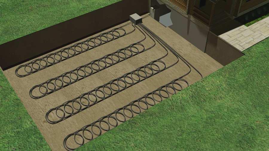
21 Vertical & Horizontal Slinky System Horizontal Slinky System 21
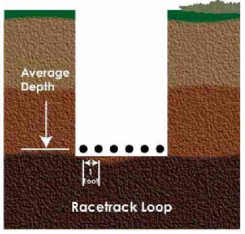
22 Horizontal Loop System EARTH TUBES 22


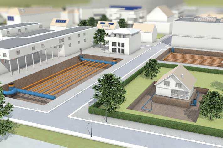
23 COMMERCIAL APPLICATIONS Often the system is linked with a mechanical ventilation system with heat recovery but in some cases, it has been used to deliver pre-cooled air into buildings using passive stack ventilation. For a commercial project, a Tichelmann grid is used. This is a self-balancing system to ensure the air can only travel the same distance through each heat transfer pipe. The heat transfer pipe is typically DN diameter, but then header pipe could be anything from DN315 to ID1200mm pipework.the system size is based on 3m/s maximum velocity through the heat transfer pipes. COMMERCIAL APPLICATIONS 23