Solar Energy Technology and Applications
|
|
|
- Moses Walton
- 5 years ago
- Views:
Transcription
1 Solar Energy Technology and Applications Presented by Fredrick Kariithi, an MSc. Student at the Institute of Nuclear Science and Technology, University of Nairobi on Friday 30 June, 2017


2 Acknowledgements

3 Solar Radiation Physicalgeography.net

4 Solar Radiation Spectrum Wikipedia
5 Blackbody Radiation Equations
6 Solar Radiation Measurements Direct Solar Radiation arrives directly from the sun and is measured by a pyrheliometer mounted on a solar tracker Diffuse Solar Radiation is scattered by molecules, dust, clouds. Diffuse solar radiation is blue-shifted. Measured using a pyranometer a with some shading to block the direct component of global solar radiation Global Solar Radiation is the sum of these falling on a horizontal surface and is measured by a pyranometer


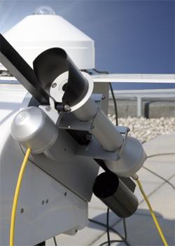
7 Solar Radiation Measuring Instruments computerclimate.com campbellsci.com pvresources.com challenges.pdf

8 Air Mass Coefficient The angle between the zenith and the direct solar beam determines the maximum radiation on the Earth s surface: Air Mass = 1 / cos Φ azom.com
9 Air Mass Coefficient AM0 is the value of the solar radiation outside the Earth s atmosphere [1.350 kw m -2 ] AM1 is the value on the Earth s surface when the Sun is overhead [ about 1kW m -2 ] AM1 to AM1.1 for equatorial and tropical regions (Φ = 0-25 )
10 Angular Variations EEC
11 Angular Variations β = angle between the line from the sun to the earth s centre and the tangent to the earth s surface a = angle between the south meridian, measured in horizontal plane westwards, and the direction of the sun z = angle between the line from the sun to the earth s centre and the normal to the earth s centre

12 Sunlight to Electricity: Photovoltaic Effect Murdoch University

13 Discoverer of Photovoltaic Effect Alexandre-Edmond Becquerel ( ) In 1839, he placed AgCl in an acidic solution, illuminated it while connected to platinum electrodes and observed the generation of voltage and current Wikipedia

14 Photovoltaic Effect Solarlove.org
15 Photovoltaic Effect In a Si PV cell, a thin n-type (phosphorus-doped) layer lies on top of a p-type (boron-doped) layer forming a p-n junction between them and across which an electric field develops Sunlight is absorbed by the n-type layer dislodging electrons from atoms By providing an external path for these electrons to flow to the p-type layer using a conductor connected to a load, the direct electric current generated can drive the load First solar PV module built in the Bell Labs in Further developed in the 1960s for space industry before gaining attention for non-space applications in the 1970s
16 Photovoltaic Cell Output Depends on the following: Current depends on illumination and area Voltage depends on built-in field [~ 0.6V for Si] Efficiency depends on illumination, semiconductor material and cell structure [~5-20 %] Power available depends on load resistance and on cell s current-voltage characteristic

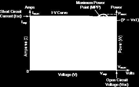
17 Current-Voltage Characteristics solarserver.com

18 Photovoltaic Cell Connections alternative-energy-tutorials.com


19 Photovoltaic Cell Connections Parallel alternative-energy-tutorials.com Series EEC
20 Solar Cell I-V Characteristic Temperature Dependence ~2.2 mv drop/ C or % voltage drop per C rise pvresources.com
21 Photovoltaic Cell Equation and myelectrical.com
22 Photovoltaic Cell Parameters ni.com ηη = II MMMM VV MMMM PP IIII = II SSSS VV OOOO FFFF PP IIII FF = Fill factor P T = Theoretical maximum power I SC = Short-circuit current V OC = Open-circuit voltage I MP = Current at maximum power V MP = Voltage at maximum power P IN = Power input ~1000W/m 2
23 Photovoltaic Cell Development Crystalline silicon PV cells mainly comprise mono-crystalline silicon, poly-crystalline silicon and ribbon silicon while thin film PV cells comprise cadmium-telluride (CdTe), copper-indium diselenide (CIS), copper-indium gallium diselenide (CIGS), amorphous silicon (a-si) Cost and efficiency are connected in a complicated manner: the best cells are highly efficient but require expensive singlecrystal semiconductor material. They use advanced structures to reduce energy losses. Crystalline silicon has about 90% of the world market
24 Photovoltaic Cell Development Thin-film cells are cheaper, use less material, but are less efficient. About 10% of the world market. Amorphous silicon is well-established but is <5% of the world market Newer thin-film materials include CdTe and organic polymers The impact of lower efficiency is the increased array area to provide the same output: A Single-crystal Si module with η =16% requires ~7 m 2 per KWp An amorphous Si module with η = 7% requires ~16 m 2 per KWp
 Sustainable and abundant; potential for <$0.15/watt Challenges: durability, degradation and device toxicity Image Sources: http://geotech.com, http://ee.t.u-tokyo.ac.")
25 Photovoltaics The Future Perovskite Calcium Titanium Oxide mineral as absorption material 3% efficient in 2009, 16%+ today Can be semitransparent (façade applications, solar paint?) Sustainable and abundant; potential for <$0.15/watt Challenges: durability, degradation and device toxicity Image Sources:

26 Photovoltaics The Future Quantum Dots Nanocrystals made of semiconducting materials Generates more electrons than absorbed photons Potential for 66% efficiency Same challenges as perovskite Image Sources:
27 Development of Laboratory Solar Cell Efficiencies Graph: Simon Philipps, Fraunhofer ISE 2016
28 Hybrid Photovoltaic-Thermal Systems Hybrid photovoltaic-thermal (PV/T) modules generate heat and electricity simultaneously in one module The basic idea of the concept is to utilize more of the solar radiation by also harvesting the waste heat that is generated in photovoltaic (PV) modules Since PV cells generally become less efficient with increasing cell temperature, the heat removal has a double benefit: the waste heat is utilized and the modules are cooled

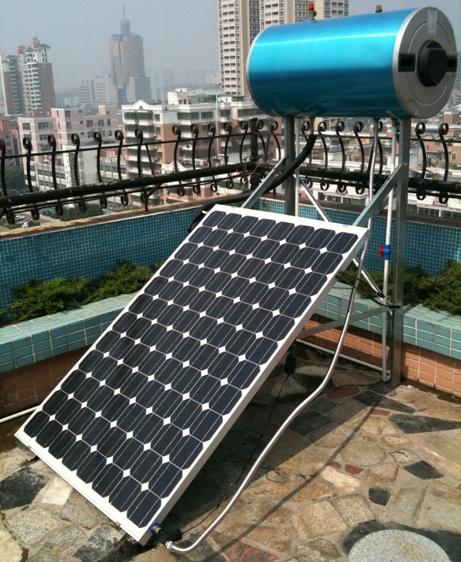
29 Hybrid Photovoltaic-Thermal Systems rinnovabilandia.it tessolarwater.com
30 Photovoltaic System Losses Reflection Shadowing of the array Heat (decreases efficiency) Mismatching in the array Resistance of contacts in the clips, the connectors, the switches and the fuses Losses in the inverter
31 Balance of System Photovoltaic cells and arrays produce DC electrical power which should be converted to AC for most applications and for grid-connected arrays Inverters are high power electrical oscillators, performing the inverse function to rectifiers, i.e. produce an AC output from a DC input For feeding electrical power into the grid ( grid-tie inverters ) they must synchronize their frequency with the grid supply and must cutoff rapidly if there is a black-out. They typically have >95% conversion efficiency
32 Balance of System Since PV outputs vary with operating conditions, inverters will also have some capability for peak power tracking to provide a constant voltage For stand-alone systems, the inverter may operate with a storage battery that is charged by the PV array and may also act with an AC source to charge the battery if it is not receiving PV power
33 Inverter Sizing Output of a grid-connected PV system depends on the PV/inverter sizing ratio* = PV array capacity (at standard conditions) / Inverter rated input capacity Optimal sizing depends on local climate, surface orientation and inclination, and inverter cost Inverter efficiency drops with part-load operation or with overload, resulting in energy loss * K. Peippo, P. D. Lund, Optimal sizing of solar array and inverter in grid-connected photovoltaic systems, Solar Energy Materials and Solar Cells 32, pp , 1994
34 Inverter Sizing
35 Inverter Lifetime The lifetime of electrolytic capacitors is extremely dependent on ripple current and ambient temperature. Therefore standard inverters usually have lifetimes of up to 40000h In (Fundamental Frequency Front End) F3E-based PV inverters, plastic capacitors are used to improve lifetime: working at the maximum 3-phase voltage of 480V these capacitors still have a lifetime of h
36 Battery Charge Controller The Maximum Power Point Tracking (MPPT) charge controller is a DC to DC transformer that can transform power from a higher voltage to power at a lower voltage. The amount of power does not change (except for a small loss in the transformation process). Therefore, if the output voltage is lower than the input voltage, the output current will be higher than the input current, so that the product P = V x I remains constant. Enables up to 30% energy yield Efficiency can go up to 98% and provide over-charging protection

37 Inverters victronenergy.com
38 Battery Charge Controller Pulse Wide Modulation (PWM) charge controller reduces the voltage from the PV module to that of the battery, resulting in a decrease in efficiency. PWM charge controller, works based on 1/2/3 or 4-stage charging method, switching between constant stages according to the available PV voltage and current. The efficiency loss depends on the difference in amounts of voltage between PV modules and batteries PWM charge controllers are less expensive (than MPPT) and are an ideal solution for smaller PV systems where the price can be a critical point, or where the maximum efficiency (as in MPPT 98%) and additional power is not really needed (pvshop.eu)

39 Price Trends of Photovoltaics Current and Future Cost of Photovoltaics, Fraunhofer ISE (2015)
40 Price Trends of Photovoltaic Technologies Module pricing driven by efficiency Lux Research (2010), Module Cost Structure Breakdown
41 Photovoltaic Payback An additional consideration is the pay-back period which may be faster for cheaper, lower efficiency arrays, provided their lifetime is not too short. There is also an energy payback time, connected with the financial payback but of more concern to energy supply strategy Material usage for silicon cells has been reduced significantly during the last 10 years from around 16 g/w p to less than 6 g/w p due to increased efficiencies and thinner wafers The Energy Payback Time of PV systems is dependent on the geographical location: PV systems in Northern Europe need around 2.5 years to balance the input energy, while PV systems in the South equal their energy input after 1.5 years and less, depending on the technology installed
42 Photovoltaic Payback A PV system located in Sicily with multi-si modules has an Energy Payback Time of around one year. Assuming 20 years lifespan, this kind of system can produce twenty times the energy needed to produce it The Energy Payback Time for CPV-Systems in Southern Europe is less than 1 year
43 Energy Payback Time (EPBT) EPIA Sustainability Working Group Fact Sheet 2011; since 2010: M.J. de Wild- Scholten2013. Graph: PSE AG 2014
44 Energy Payback Time (EPBT) Depending on the technology and location of the PV system, the EPBT today ranges from 0.7 to 2 years Rooftop PV systems produce net clean electricity for approx. 95 % of their lifetime, assuming a life span of 30 years or more
45 Calculating Energy from PV (SAP-UK, 2016) In the UK, for Standard Assessment Procedure (SAP) calculations, the energy produced per year depends on the installed peak power (kw p ) of the PV module PV modules are available in a range of types and some produce more electricity per square metre than others, and the peak power depends on the type of module as well as its effective area The procedure for PV is as follows: 1) Establish the installed peak power of the PV unit (kw p ) 2) The electricity produced by the PV module, EPV (kwh/year), is calculated as follows:
46 Calculating Energy from PV (SAP-UK, 2016) a. If an Microgeneration Certificate Scheme (MCS) certificate for the installation is available E PV = 0.8 x kw p x S x SF (M1a) b. If no MCS certificate is available E PV = 0.8 x kw p x S x Z PV,far x Z PV,near (M1b) where S is the annual solar radiation (kwh/m²) for the applicable climate and orientation and tilt of the PV, SF is the shading factor from the MCS certificate and Z PV,near and Z PV,far are overshading factors from Tables M1 and M2.
47 Calculating Energy from PV (SAP-UK, 2016) If multiple near obstructions are present, instances of Z PV,near are combined by multiplication If there is more than one PV array, e.g. at different tilt or orientation, apply equation (M1) to each and sum the annual electricity generation

48 Calculating Energy from PV (SAP-UK, 2016)
 22 i.e.")
49 Calculating Energy from PV (SAP-UK, 2016) 22 i.e. from East to West, through South
50 Solar Resource Kenya is located near the equator, which provides it with 4-6 kilowatt-hour per square meter per day (kwh/m 2 /day) levels of insolation. The average daily radiation in over 28,000 square kilometers is above 6 kwh/m 2 /day. (Boampong, R. and Phillips, M. A. Renewable energy incentives in Kenya: Feedin-tariffs and Rural Expansion, 2016) In total, 39 African countries have a solar resource that exceeds 2,000 kwh/m²/year. Namibia, with a solar resource of 2,512 kwh/m²/year, has the highest solar resource in Africa for its capital (Solar PV in Africa: Costs and Markets IRENA 2016)
 Spatial Modelling of Solar Energy Potential in")
51 Estimated Solar Energy Potential (Kenya) Oloo et al. (2016) Spatial Modelling of Solar Energy Potential in Kenya


52 Photovoltaic Installations Guide to the Installation of Photovoltaic Systems (2012) by the Microgeneration Certification Scheme ( MCS )
 Technical and Economical Assessment of Net-Metering in Kenya UNEP s rooftop solar plant (515 kwp) Key facts: - 515 kwp installed (2011) - Grid connection, but no feeding-in - Commercial")
53 Some Solar PV Installations in Kenya Hille et al. (2011) Technical and Economical Assessment of Net-Metering in Kenya UNEP s rooftop solar plant (515 kwp) Key facts: kwp installed (2011) - Grid connection, but no feeding-in - Commercial procurement by UNEP Realized by: Energiebau Solarstromsysteme GmbH - Components: o Modules: Schott Solar, Kaneka o Inverters: SMA Solar Systems
 Technical and Economical Assessment of Net-Metering in Kenya SOS Children s Village Mombasa (60 kwp) Key facts: - 60 kwp system - Grid connection, feeding-in at peak production - Commercial")
54 Some Solar PV Installations in Kenya Hille et al. (2011) Technical and Economical Assessment of Net-Metering in Kenya SOS Children s Village Mombasa (60 kwp) Key facts: - 60 kwp system - Grid connection, feeding-in at peak production - Commercial procurement by SOS CV - Realized by: Asantys Systems GmbH, African Solar Designs (ASD) Ltd. - Components: o Modules: Centrosolar AG, o Inverters SMA Solar Systems

55 Some Solar PV Installations in Kenya Strathmore University in Madaraka: Produces over 600 kw which consists of 2,400 solar panels and 30 inverters. Supplies between MWh into the national grid every year. Set up at a cost of $1.3 million serc.strathmore.edu

56 Solar Irradiance Depending on Surface Orientation EEC
57 Series or Parallel Connection PV modules can be connected in parallel, series or a combination. The choice consequently determines the voltage and current from the PV array and also the choice of appropriate inverter(s) The inverter may be a single one for the whole system (from 1kW to 1000kW of rated output) Or it may be one inverter per string of modules, with strings then combined (0.7kW to 5kW of rated output) Or one inverter for every module (0.1kW to 0.7kW of rated output)
58 Series or Parallel Connection
59 Series or Parallel Connection Remember that in series the output is a current equal to that from a single module but a voltage equal to the sum of all module voltages; and in parallel the output is a current equal to the sum of all module currents but a voltage equal to that from a single module (Higher voltages give smaller resistance losses in leads and connectors)
60 Type of PV to Use For domestic and small scale PV arrays, modules usually use mono-crystal or poly-crystal Si. There are no obvious reasons except that mono-crystal arrays are more efficient and so require smaller area for the same output, but poly-crystal arrays are cheaper. They both have a dark blue or black color but poly-crystal Si is textured

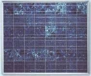
61 Type of PV to Use Mono-crystal Poly-crystal
62 Points to Note during Installation For modules integrated into the roof or with poor rear face ventilation, it is especially important for the temperature coefficient to be the lowest possible Another parameter one which should take into account is the resistance to storms and hail One should also consider that any framing can collect dirt and may not be aesthetically pleasing
63 Points to Note during Installation Finally it is necessary to take into account the weight and the overall dimensions that can make the installation itself difficult. Large modules require fewer fixing points (relative to total array output power) but impose constraints in their arrangement on the useful roof surface. Bear in mind that spaces between the modules (some cm) are useful for good ventilation. The size of the modules will also be influenced by the available transport and site accessibility
64 Shadowing Problems arise if modules are overshadowed by nearby buildings or trees or adjacent modules EEC

65 Shadowing of Cells in a String Each cell in a series connection must pass the same current. A shaded cell will generate less current and so will act as a load for the photocurrent in the string EEC
66 Shadowing of Cells in a String This will cause a shaded cell to heat up and will reduce the output voltage. To avoid this, it is possible to add a by-pass diode across the string or across the module to provide a current path. This introduces a small voltage drop but avoids local heating of the shaded cell and limits the array s output reduction. However, a diode may fail as a short circuit

67 Solar Tracking Arrays Alter the inclination every hour to follow the sun from east to west and/or alter the tilt each month: in summer the panel is more horizontal, in winter more vertical EEC
68 Testing Inspection and testing of a completed system must be to BS 7671 and documented, a requirement of Building Regulations Note that DC circuits carry greater risk than AC circuits, as electrical contact causes continuous muscular contraction rather than a spasm Be aware of possible earth leakage paths if one side of the DC circuit is bonded to earth Photovoltaics in Buildings DTI guide to the installation of PV systems offers guidance on what is required and what labels should be applied to system components
69 Effect of Lightning Strike Where there is a perceived increase in risk of direct strike as a consequence of the installation of the PV system, specialists in lightning protection should be consulted with a view to installing a separate lightning protection system in accordance with BS Note: It is generally accepted that the installation of a typical roofmounted PV system presents a very small increased risk of a direct lightning strike. However, this may not necessarily be the case where the PV system is particularly large, where the PV system is installed on the top of a tall building, where the PV system becomes the tallest structure in the vicinity, or where the PV system is installed in an open area such as a field. DTI Photovoltaics in Buildings Guide to the Installation of PV Systems (2 nd Ed)
70 Maintenance Although, in general, a photovoltaic system is extremely reliable, preventive maintenance is recommended at least every year and more frequently if in coastal or industrial sites Many checks may be carried out by personnel not necessarily expert in photovoltaic technology provided they are able to operate on electric circuits, therefore applying the necessary safety procedures, and have seen the "manual for use and maintenance drafted by the designer and delivered to the end user
71 Maintenance Note that in the event of system failure when performing maintenance, there is a danger of electric shock because of voltage and current that still exist whilst the array remains exposed to light PV modules: Visual inspection & electrical connections Strings of modules: Check uniformity of current and voltage for each string
72 Maintenance Support structures: Check mechanical stability, weathering, corrosion, moving parts Switchgear: Check cabinet and insulation (heating, rodents, etc.), blocking diodes, switches, circuit breakers, wiring/insulation
73 Maintenance Batteries: Acid level and electrolyte density, corrosion Inverters: Follow manufacturer s inspection instructions
74 Safety Islanded operation is not allowed (must disconnect if grid fails) Latest IEE wiring regulations Cabling Overcurrent protection DC & AC isolation Manual isolation switch Bonding to main earthing terminal within equipotential zone of the installation
75 Safety Type verified equipment complies with: Automatic disconnection and delayed reconnection requirement Quality of supply regarding harmonics and flicker Power factor control Type tests, etc
76 Regulations, Standards and Warranties The Energy Act offers general guidelines in Kenya regarding the licensing of personnel and other key players in the solar PV sector, among others A manufacturer may offer a warranty for certain properties of a product, and for photovoltaic modules this may be a guaranteed output power. Typically it is ensured that, after 20 years, the power of a PV module will be at least 80% of the original nominal power, e.g. With a nominal power of 200 W p and a tolerance of 5%, the PV module after 20 years should still give 152 W p power (200 W p - 5% - 20% = 152 W p )
 by the Ministry of Energy")
77 PV Feed in Tariffs (FiTs) Proposed Feed-in-Tariff policy for renewable energy (solar energy) by the Ministry of Energy (2012)


78 Applications of Solar PVs wifinotes.com thriftenergy.co.uk


79 Applications of Solar PVs reuk.co.uk vimalelectronics.com
80 Applications of Solar PVs Lighting in residential, streets, institutional and commercial space Generating power to feed into the grid Industrial use to power equipment e.g., pumps, motors Powering consumer electronics e.g., TV sets, radio, laptops Space industry Water heating Telecommunication base stations Transport industry
81