Geotechnical Engineering Report
|
|
|
- Meryl Stevenson
- 5 years ago
- Views:
Transcription
1 Geotechnical Engineering Report Coquina Beach Drainage Improvements Bradenton Beach, Florida July 16, 2018 Dunkelberger Project No. HC1032 Prepared for: Manatee County Construction Services Division Bradenton, Florida Prepared by: Dunkelberger Engineering & Testing, a Terracon Company Sarasota, Florida


2 July 16, 2018 Manatee County Construction Services Division 1112 Manatee Avenue, Suite 868C Bradenton, FL 3420 Attn: Mr. Michael Sturm, P.E. Project Manager Re: Geotechnical Engineering Report Coquina Beach Drainage Improvements Bradenton Beach, Manatee County, Florida DUNKELBERGER Project Number: HC1032 Dear Mr. Sturm: Dunkelberger Engineering & Testing, a Terracon Company (DUNKELBERGER) has completed the geotechnical engineering services for the above referenced project. This study was performed in general accordance with Manatee County, Florida Work Assignment No. W , dated October 20, 201. This report presents the findings of the subsurface exploration and provides geotechnical recommendations concerning earthwork and the design and construction of pervious pavements and groundwater control for the proposed project. We appreciate the opportunity to be of service to you on this project. If you have any questions concerning this report, or if we may be of further service, please contact us. Sincerely, Dunkelberger Engineering & Testing, a Terracon Company James M. Jackson, P.E. Douglas S. Dunkelberger, P.E. Project Engineer Principal FL License No.: FL License No.: Enclosures cc: 1 Client (PDF) 1 File Dunkelberger Engineering & Testing, A Terracon Company 8260 Vico Court, Unit B Sarasota, Florida P [941] F [941] dunkelberger-engineering.com
3 TABLE OF CONTENTS INTRODUCTION... 1 PROJECT INFORMATION Project Description Site Location and Description... 2 SUBSURFACE CONDITIONS Site Geologic Conditions Soil Survey Typical Profile Groundwater Double Ring Infiltration Test and Borehole Permeability Test... RECOMMENDATIONS FOR DESIGN AND CONSTRUCTION Geotechnical Considerations Demucking/ Removal and Replacement Earthwork... 7 Site Preparation... 7 Material Requirements... 7 Compaction Requirements-Mass Fill Areas... 8 Utility Trench Backfill Pervious Pavements... 8 Subgrade Preparation... 8 Underdrain Design Temporary Dewatering Year Erosion Protection Line... 9 Additional considerations... 9 GENERAL COMMENTS... Responsive Resourceful Reliable
4 TABLE OF CONTENTS (continued) APPENDIX A FIELD EXPLORATION Exhibit A-1 Topographic Vicinity Map Exhibit A-2 Soil Survey Map Exhibit A-3 Soil Survey Description Exhibit A-4 Boring Location Plan Exhibit A- Field Exploration Description Exhibit A-6 to A-3 Boring Logs Exhibit A-36 to A-39 DRI Test Results Exhibit A-40 Groundwater Contour Map APPENDIX B LABORATORY TESTING Exhibit B-1 Laboratory Testing Procedures APPENDIX C SUPPORTING DOCUMENTS Exhibit C-1 General Notes Exhibit C-2 Unified Soil Classification System APPENDIX D ANDREYEV ENGINEERING GROUNDWATER MODELING REPORT APPENDIX E TAYLOR ENGINEERING 30 YEAR EROSION PROJECTION LINE Responsive Resourceful Reliable
5 Geotechnical Engineering Draft Report Coquina Beach Drainage Improvements Bradenton Beach, Florida July 16, 2018 DUNKELBERGER Project No. HC1032 EXECUTIVE SUMMARY A geotechnical study has been completed for the proposed Coquina Beach Drainage Improvements project which will be located on the west side of Gulf Drive South at Coquina Beach in Bradenton Beach, Manatee County, Florida. Thirty (30) Standard Penetration Test (SPT) borings, designated B-1 through B-30, were spaced at approximately 200-foot centers across the site. The borings were drilled to a maximum depth of 2 feet below the existing ground surface (bgs). Additionally, four (4) borehole permeability (BHP) tests and four (4) double ring infiltration (DRI) tests were run at locations spaced evenly across the site. Based on the information obtained from our geotechnical exploration, it appears that the site can be developed for the proposed project. The following geotechnical considerations were identified: Organic fine sand was found in Borings B-16, B-17, and B-20 at depths ranging from about 4 to 8 feet bgs. The organic material represents risk of more than normal settlement, particularly differential settlement, beneath the planned rigid pavement section. For that reason, we recommend that the buried organic layer be removed from the pavement areas and replaced with engineered fill. Other than the organic layer, the borings generally found fine sands with varying amounts of silt and shell fragments from the existing ground surface to the maximum borehole termination depth of 2 feet. Based upon the test boring results, the shallow soils appear to have the required strength, stiffness, and permeability for support of typical pervious pavement sections. Field-measured horizontal permeability values ranged from 0.8 to 11.3 feet per day within the depth interval of 2 to 2 feet bgs. The measured permeability rates are considered relatively slow to moderate. Field-measured vertical infiltration values ranged from 6. to 1.1 inches per hour at a depth ranging from about 1 to 2 feet bgs. The measured infiltration rates at this depth are considered moderate to relatively high. The position of the Seasonal High Groundwater Level (SHGWL) was estimated at about +1 ½ feet-navd88 on the southern half of the site and +2 feet-navd88 on the northern half of the site. Close monitoring of the construction operations discussed herein will be critical in achieving the design objectives for earthwork, pavements and sub-structure aspects of the project. We therefore recommend that DUNKELBERGER be retained to monitor this portion of the work. Responsive Resourceful Reliable i
6 Geotechnical Engineering Draft Report Coquina Beach Drainage Improvements Bradenton Beach, Florida July 16, 2018 DUNKELBERGER Project No. HC1032 This summary should be used in conjunction with the entire report for design purposes. It should be recognized that details were not included or fully developed in this section, and the report must be read in its entirety for a comprehensive understanding of the items contained herein. The section titled GENERAL COMMENTS should be read for an understanding of the report limitations. Responsive Resourceful Reliable ii
7 GEOTECHNICAL ENGINEERING REPORT COQUINA BEACH DRAINAGE IMPROVEMENTS BRADENTON BEACH, MANATEE COUNTY, FLORIDA DUNKELBERGER Project No. HC1032 July 16, 2018 INTRODUCTION A geotechnical study has been completed for the proposed Coquina Beach Drainage Improvements project which will be located on the west side of Gulf Drive South at Coquina Beach in Bradenton Beach, Manatee County, Florida. Thirty (30) Standard Penetration Test (SPT) borings, designated B-1 through B-30, were spaced at approximately 200-foot centers across the site. The borings were drilled to a maximum depth of 2 feet below the existing ground surface (bgs). Additionally, four (4) borehole permeability (BHP) tests and four (4) double ring infiltration (DRI) tests were run at locations spaced evenly across the site. Logs of the borings along with a boring location plan are included in Appendix A of this report. The purpose of these services is to provide information and geotechnical engineering recommendations relative to: subsurface soil conditions pervious pavement design and groundwater conditions construction earthwork drainage and groundwater control design PROJECT INFORMATION 2.1 Project Description Item Site layout Grading Pavements Groundwater Control Description See Appendix A, Exhibit A-4: Boring Location Plan Assumed to be minimal (i.e. less than 1 foot) Approximately 173,728 square feet (sf) of 8-inch thick pervious concrete pavement and 97,70 sf of -inch thick pervious concrete pavement; the pervious concrete is to be directly underlain by either 4inches of Bold & Gold Media or Select Fill An underdrain system (FDOT Type II Underdrain) is planned for groundwater control Responsive Resourceful Reliable 1
8 Geotechnical Engineering Draft Report Coquina Beach Drainage Improvements Bradenton Beach, Florida July 16, 2018 DUNKELBERGER Project No. HC1032 If project conditions are different than the assumptions given above, then we should be advised to allow for re-evaluation of the recommendations and conclusions presented in this report. 2.2 Site Location and Description Item Location Existing improvements Current ground cover Existing topography Description The project is to be located on the west side of Gulf Drive South at Coquina Beach in Bradenton Beach, Florida Shell-stabilized parking and drive areas cover the majority of the site; an asphalt paved bus loop exists near the midpoint of the site Sand-shell soil mixture Based information obtained from ZNS Engineering, the site appears to slope upward from the south to the north from an elevation of about +3 to +6 feet-navd88 SUBSURFACE CONDITIONS 3.1 Site Geologic Conditions The Florida Geological Survey Bulletin No. 68, issued in 2008, was reviewed to describe the general geological and hydrogeological conditions for the area. The Florida Geological Survey shows that the area is comprised of the Tampa Member of the Arcadia Formation. In general, the uppermost 20 feet of the land surface is mapped with Holocene sediments, which include quartz, sands, carbonate sands and muds, and organics. Holocene sediments occur near the present coastline at elevations generally less than feet. The surficial aquifer system consists primarily of undifferentiated sands, shell material, silts, and clayey sands. 3.2 Soil Survey The Soil Survey of Manatee County, Florida (i.e. Soil Survey), issued December 1984 and published by the Soil Conservation Service (U.S. Department of Agriculture), was reviewed to determine the surficial soil map units at this site. The soil survey map, which is shown on Exhibit A-2 in Appendix A indicates that the southern third of the site is mapped with Soil Unit 8, Canaveral fine sand, and the northern two-thirds of the site is mapped with Soil Unit, Canaveral fine sand, organic substratum and Soil Unit 9, Canaveral fine sand, filled. Unit 8, Canaveral fine sand, consists of fine sands with shell fragments to a depth of 6 inches. The Seasonal High Groundwater Table (SHGWT) is at a depth of to 40 inches for 2 to 6 months out of the year. Unit 9, Canaveral fine sand, fill, and Unit, Canaveral fine sand, organic substratum consist of fill material made up of fine sand and shell fragments. However, a layer of muck is present in Unit from a depth of about 4 to 70 inches and in a few small areas of Unit 9 at a depth of 80 Responsive Resourceful Reliable 2
9 Geotechnical Engineering Draft Report Coquina Beach Drainage Improvements Bradenton Beach, Florida July 16, 2018 DUNKELBERGER Project No. HC1032 inches or more. The SHGWT is dependent on the thickness of the fill material for these two soil units, but, is reported to lie at a depth of 30 to 60 inches bgs. Permeability in these sand and fill materials is very rapid and is moderately rapid in the organic (i.e. muck) layer. Detailed descriptions of the soils mapping units can be found on Exhibit A-3 in Appendix A. It should be noted that the Soil Survey is not intended as a substitute for site-specific geotechnical exploration; rather it is a useful tool in planning a project scope in that it provides information on soil types likely to be encountered. 3.3 Typical Profile Based on the results of the borings, subsurface conditions on the project site can be generalized as follows: Stratum Approximate Depth to Bottom of Stratum (feet) 1, Material Description Fine SAND (SP, SP-SM) with trace to slight amounts of silt, occasionally with trace to some shell fragments Organic fine SAND (PT, SM), sometimes with tree debris 4 17 ½ Silty fine SAND (SM) 1. Only found in Borings B-16, B-17, and B-20. Consistency/ Density Very Loose to Very Dense Very Loose to Loose Very Loose to Loose Conditions encountered at each boring location and results of laboratory testing are indicated on the individual boring logs. Stratification boundaries on the boring logs represent the approximate location of changes in soil types; in-situ, the transition between materials may be gradual. Details for each of the borings can be found on the boring logs in Appendix A of this report. Descriptions of our field exploration are included as Exhibit A- in Appendix A. Descriptions of our laboratory testing procedures are included as Exhibit B Groundwater Groundwater levels were measured on November 12 to 17, 201 at 24 hours after the completion of drilling and are shown in the table below. Responsive Resourceful Reliable 3
10 Geotechnical Engineering Draft Report Coquina Beach Drainage Improvements Bradenton Beach, Florida July 16, 2018 DUNKELBERGER Project No. HC1032 Boring No. GSE 1 (feet- NAVD) Measured Groundwater Depth (feet-bgs) Measured Groundwater Elevation (feet-navd) Estimated SHGWL based on SCS (feet-bgs) Estimated SHGWL (feet-navd) B ½ B ½ B ½ B ½ B ½ B ½ B ½ B ½ B B B B B B B GSE = Ground Surface Elevation provided by ZNS Engineering. The groundwater level was not measured in the -foot deep SPT borings due to the boreholes being collapsed at 24hours after the completion of drilling. Therefore, only the groundwater data from the 2-foot deep SPT borings were considered for our SHGWL estimates. As seen in the table above, the groundwater measurements ranged from about +½ feet-navd88 (2 ½ to 3 ½ feet bgs) on the southern half of the site to about +1 foot-navd88 (3 to 4 ½ feet bgs) on the northern half of the site. The groundwater levels are likely to closely mimic average water levels in the nearby Gulf of Mexico and Sarasota Bay. Groundwater levels are probably also influenced, to a lesser degree, by ground surface elevation change across the site and seasonal variations in rainfall. As presented herein, the SHGWL is considered to be the highest sustained groundwater elevation during a typical (normal or average rainfall amount) wet season, coupled with high tide conditions, and not the peak groundwater elevation immediately following a major storm event. Therefore, the SHGWL referred to in this report is an average, high value and not necessarily a peak (upper bound) value. Based on review of tide tables for the site area, the average tide level in the Gulf of Mexico was about +0.1 feet-navd for 201. Additionally, the SCS soil survey indicates that our measured Responsive Resourceful Reliable 4
11 Geotechnical Engineering Draft Report Coquina Beach Drainage Improvements Bradenton Beach, Florida July 16, 2018 DUNKELBERGER Project No. HC1032 groundwater levels are near the lower end of the estimated SHGWL which can be attributed to the seasonally dry conditions. Accordingly, we made a 1 foot upward (seasonal) adjustment to our measured groundwater levels. On that basis, we estimate the SHGWL will at about +1 ½ feet- NAVD88 in the southern half of the site and about +2 feet-navd in the northern half of the site which is consistent with the mid-range of the predicted SCS values. A groundwater contour map is provided on Exhibit A-40 in Appendix A. 3. Double Ring Infiltration Test and Borehole Permeability Test The results of the field double ring infiltration (DRI) tests are summarized in the table below. Location Depth (feet) USCS Classification Infiltration (in/hr) DRI-1 1 SP-SM 9.3 DRI-2 1. SP-SM 1.1 DRI-3 2 SP-SM 1.1 DRI-4 1 SP-SM 6. The results of the field borehole permeability (BHP) tests are summarized in the table below. Location Screened Interval (ft) Horizontal Permeability, K h (ft/day) Vertical Permeability, K v (ft/day) BHP BHP BHP BHP The horizontal permeability values were calculated using an equation for a single packer test set-up. The field data was input into an equation developed by the U. S. Bureau of Reclamation, and presented by Harry Cedergren in his text Seepage, Drainage and Flow Nets, published in 1977, which is as follows: k h = q 2p Lh log e L R For L greater than or = r k h = Permeability, feet/sec; q = flow, cfs L = Screen length, feet; h = head, feet Responsive Resourceful Reliable
12 Geotechnical Engineering Draft Report Coquina Beach Drainage Improvements Bradenton Beach, Florida July 16, 2018 DUNKELBERGER Project No. HC1032 r = Borehole radius, feet The vertical permeability values were assumed to be half of the calculated horizontal permeability values. RECOMMENDATIONS FOR DESIGN AND CONSTRUCTION 4.1 Geotechnical Considerations Organic sand, with organic contents ranging from about 7 to 16 percent, was encountered in Borings B-16, B-17, and B-20 at depths ranging from about 4 to 8 feet bgs. Based on the 201 version of Florida Department of Transportation (FDOT) Standard Index No. 00, organic soils should be removed from the planned pavement areas when the average organic content exceeds percent or an individual organic content test exceeds 7 percent. Therefore, on this basis, the organic material encountered in the borings is considered unsuitable for construction of the proposed pavement and should be removed from the pavement areas and replaced with engineered fill. Recommendations for demucking can be found in Section 4.2 of this report. We recommend additional field exploration, via hand augured borings, at and around the three test borings that contained organic material (i.e. muck). The additional data will allow for more specific parameters (lateral and vertical extent) related to removal of unsuitable deposits. The soil survey shows that much of the site is mapped with Soil Units 9 and which contain an organic substratum. Therefore, it is likely the additional borings may find a more widespread organic soil condition. Other than the organic material, the borings found fine sands with varying amounts of silt and shell fragments to the maximum borehole termination depth of 2 feet bgs. According to information provided on the National Ready Mixed Concrete Associations (NRMCAs) internet website, these materials, following improvement of relative density at shallow depths, should meet the required stiffness, strength, and drainage characteristics to provide adequate subgrade support for the pervious pavement sections. We recommend that 4 inches of Select Fill meeting the material requirements specified in Section be placed beneath the bottom of the pervious pavement. Design and construction recommendations for pervious pavement sections and the underdrain system are outlined below. 4.2 Demucking/ Removal and Replacement 1. The organic materials (i.e. organic fine sand and tree debris) should be removed in their entirety from the planned pavement areas in accordance with the guidelines of FDOT Responsive Resourceful Reliable 6
13 Geotechnical Engineering Draft Report Coquina Beach Drainage Improvements Bradenton Beach, Florida July 16, 2018 DUNKELBERGER Project No. HC1032 Standard Index No. 00. The excavated organic material should be disposed of off-site. The sand soils, overlying the organic layer, could be stockpiled on site and re-used as excavation backfill provided that they meet the material requirements presented below in Section Removal of the organic fill soils will require dewatering to facilitate the excavation work and permit the visual inspection of the excavation bottom. 3. The bottom of the de-mucked excavation should be visually inspected by a DUNKELBERGER engineer to verify satisfactory removal of the organic fill soils. 4. The resulting excavation should be backfilled, in the dry, with well-compacted granular soil as further described in the following recommendations. 4.3 Earthwork Site Preparation Following the recommended demucking, earthwork operations should continue with the removal of the existing shell-stabilized parking and drive areas, and stripping of any remaining surficial organic soil (topsoil) from the planned pavement areas. Topsoil should be removed from the construction areas. The shell-stabilized sand material can be stockpiled for re-use as backfill in the demucking excavations and as general fill. Wet or dry material should either be removed or moisture conditioned and re-compacted. After demolition, stripping, and grubbing, the exposed surface should be proof-rolled to aid in locating loose or soft areas. Proof-rolling should be performed with a fully-loaded, tandem-axle dump truck or front-end loader. The roller should make a minimum of eight overlapping passes over all areas of the site, the latter four passes at right angles to previous passes. The soils should be compacted sufficiently to obtain a minimum compaction as defined in Section Unstable soil (pumping) should be removed or moisture conditioned and compacted in place prior to placing fill. Material Requirements Engineered fill should meet the following material property requirements: Fill Type USCS Classification Acceptable Location for Placement Select General 1 SW, SP, GW, GP (fines content < percent, maximum particle size < 1 inch, organic content < 2 percent) SP, SP-SM (fines content < 12 percent, maximum particle size < 2 inches, organic content < 3 percent) Between the bottom of pavement and top of subgrade/general fill; at least 4 inches thick At all locations and elevations beneath the Select Fill 1. Strata 1 and 2 soils at this site appear to meet this criterion. Soils with fines content > 12 percent may retain moisture and be difficult to compact and achieve specified density and stability. These soils may need to be maintained dry of optimum to properly compact. Responsive Resourceful Reliable 7
14 Geotechnical Engineering Draft Report Coquina Beach Drainage Improvements Bradenton Beach, Florida July 16, 2018 DUNKELBERGER Project No. HC1032 Compaction Requirements-Mass Fill Areas Item Fill Lift Thickness Minimum Compaction Requirements Moisture Content 1 Minimum Testing Frequency Description 12 inches or less in loose thickness when heavy vibratory compaction equipment is used. Maximum particle size should not exceed 2 inches in a 12-inch lift. 4 to 6 inches in loose thickness when hand-guided equipment (i.e. jumping jack or plate compactor) is used. Maximum particle size should not exceed 1 inch in a 4- to 6-inch lift. Greater than one foot below pavement subgrade elevation should be compacted to at least 9 percent of the maximum dry density as determined by the Modified Proctor Test (ASTM D-17). The upper one foot of pavement subgrades should be compacted to between 92 and 9 percent of the maximum dry density as determined by the Modified Proctor Test (ASTM D-17). Within ±2 percent of optimum moisture content as determined by the Modified Proctor test, at the time of placement and compaction One field density test per,000 square feet. 1 We recommend that engineered fill be tested for moisture content and compaction during placement. Should the results of the in-place density tests indicate compaction limits have not been met, the area represented by the test should be reworked and retested as required until achieving the compaction requirements.. Utility Trench Backfill All trench excavations should be made with sufficient working space to permit construction including backfill placement and compaction. 4.4 Pervious Pavements Subgrade Preparation Site grading is typically accomplished relatively early in the construction phase. Fills are placed and compacted in a uniform manner. However, as construction proceeds, excavations are made into these areas, rainfall and surface water saturates some areas, heavy traffic from concrete trucks and other delivery vehicles disturbs the subgrade and many surface irregularities are filled in with loose soils to temporarily improve ride comfort. As a result, the pavement subgrades, initially prepared early in the project, should be carefully evaluated as the time for pavement construction approaches. We recommend the moisture content and density of the top 12 inches of the subgrade be evaluated and the pavement subgrades be proof rolled and tested within two days prior to commencement of actual paving operations. Compaction tests should be performed at a frequency of 1 test per,000 square feet or fraction thereof. Areas not in compliance with the required ranges of moisture or density should be moisture conditioned and re-compacted. Particular attention should be paid to high traffic areas that were rutted and disturbed earlier and to areas where backfilled Responsive Resourceful Reliable 8
15 Geotechnical Engineering Draft Report Coquina Beach Drainage Improvements Bradenton Beach, Florida July 16, 2018 DUNKELBERGER Project No. HC1032 trenches are located. Areas where unsuitable conditions are found should be repaired by removing and replacing the materials with properly compacted fills. After proof-rolling and repairing deep subgrade deficiencies, the entire subgrade should be scarified and prepared as recommended in Section 4.3 of the Earthwork section this report to provide a uniform subgrade for pavement construction. Areas that appear severely desiccated following site stripping may require further undercutting and moisture conditioning. If a significant precipitation event occurs after the evaluation or if the surface becomes disturbed, the subgrade should be reviewed by qualified personnel immediately prior to paving. The subgrade should be in its finished form at the time of the final review. Underdrain Design Based on the results of the groundwater modeling completed by Andreyev Engineering, Inc., we recommend a FDOT Type II underdrain be installed at approximate intervals of 60 feet throughout the pervious pavement area or beneath the centerline of the drive lane along the east end of the project. Underdrains should be designed to have positive outfall. Cleanout points should be designed and installed to allow periodic maintenance of the underdrain system. The underdrain should be consistent with the Underdrain Detail provided on Sheet 12 of the Conceptual Plan by the Manatee County Public Works department, dated August 201. We recommend that the coarse aggregate consist of FDOT No. 7 stone or equivalent wrapped in a FDOT Type D-3 filter fabric. A report summarizing the groundwater modeling analysis is included in Appendix D of this report. 4. Temporary Dewatering Dewatering will be needed to facilitate earthwork, specifically demucking, and underground utility installation operations for this project. Actual dewatering means and methods should be left up to a contractor experienced in installation and operation of dewatering systems. The contractor should provide a dewatering plan for review and approval by the engineer prior to the installation of the dewatering systems Year Erosion Protection Line Taylor Engineering, Inc. completed a historical beach recession analysis and estimate of the position of the Mean High Water (MHW) line 30 years from the present for the site. The entire Taylor Engineering report is included in Appendix E of this report. ADDITIONAL CONSIDERATIONS Responsive Resourceful Reliable 9
16 Geotechnical Engineering Draft Report Coquina Beach Drainage Improvements Bradenton Beach, Florida July 16, 2018 DUNKELBERGER Project No. HC1032 We recommend that additional exploratory borings be drilled within the proposed pavement areas, during the design process, to better characterize the depth, thickness, and lateral extent of the organic sands. To do that, we recommend to 12-foot deep auger borings be drilled in a gridlike pattern around the Borings B-16, B-17, and B-20. GENERAL COMMENTS DUNKELBERGER should be retained to review the final design plans and specifications, prior to contractor bidding, so comments can be made regarding interpretation and implementation of our geotechnical recommendations in the design and specifications. DUNKELBERGER also should be retained to provide observation and testing services during grading, excavation, foundation construction and other earth-related construction phases of the project is complete. The analysis and recommendations presented in this report are based upon the data obtained from the borings performed at the indicated locations and from other information discussed in this report. This report does not reflect variations that may occur between borings, across the site, or due to the modifying effects of construction or weather. The nature and extent of such variations may not become evident until during or after construction. If variations appear, we should be immediately notified so that further evaluation and supplemental recommendations can be provided. The scope of services for this project does not include either specifically or by implication any environmental or biological (e.g., mold, fungi, and bacteria) assessment of the site or identification or prevention of pollutants, hazardous materials or conditions. If the owner is concerned about the potential for such contamination or pollution, other studies should be undertaken. This report has been prepared for the exclusive use of our client for specific application to the project discussed and has been prepared in accordance with generally accepted geotechnical engineering practices. No warranties, express or implied, are intended or made. Site safety, excavation support, and dewatering requirements are the responsibility of others. In the event that changes in the nature, design, or location of the project as outlined in this report are planned, the conclusions and recommendations contained in this report shall not be considered valid unless DUNKELBERGER reviews the changes and either verifies or modifies the conclusions of this report in writing. Responsive Resourceful Reliable
17 APPENDIX A FIELD EXPLORATION

18 SITE SCALE 1: KILOMETERS METERS 0 MILES N CONTOUR INTERVAL: FEET NATIONAL GEODETIC VERTICAL DATUM OF 1929 Project Mngr: Drawn By: Checked By: Approved By: JMJ DCV JMJ DSD Project No. HC1032 BRADENTON BEACH, FL MINUTE SERIES (TOPOGRAPHIC) TOPOGRAPHIC VICINITY MAP GEOTECHNICAL ENGINEERING REPORT COQUINA BEACH DRAINAGE IMPROVEMENTS EXHIBIT Scale: AS-SHOWN File No. Consulting Engineers and Scientists HC Date: 8260 VICO COURT, UNIT B SARASOTA, FL GULF DRIVE A PH. (941) FAX. (941) BRADENTON BEACH, MANATEE COUNTY, FLORIDA

19 SITE 9 8 SCALE 1" = 600' U.S.D.A. SOIL SURVEY FOR MANATEE COUNTY, FLORIDA ISSUED: APRIL 1983 N SOIL LEGEND 8 CANAVERAL FINE SAND 9 CANAVERAL SAND, FILLED CANAVERAL SAND, ORGANIC SUBSTRATUM POSSIBLE PRESENCE OF ORGANIC MATERIAL Project Mngr: Drawn By: Checked By: Approved By: JMJ DCV JMJ DSD Project No. Scale: File No. Date: HC1032 AS-SHOWN HC Consulting Engineers and Scientists 8260 VICO COURT, UNIT B SARASOTA, FL PH. (941) FAX. (941) SOILS MAP GEOTECHNICAL ENGINEERING REPORT COQUINA BEACH DRAINAGE IMPROVEMENTS 261 GULF DRIVE BRADENTON BEACH, MANATEE COUNTY, FLORIDA EXHIBIT A-2
20 Geotechnical Engineering Draft Report Coquina Beach Drainage Improvements Bradenton Beach, Florida January 21, 2016 DUNKELBERGER Project No. HC1032 Soil Survey Descriptions Unit 8, Canaveral fine sand, is comprised of nearly level to gently sloping, moderately well drained to somewhat poorly drained soil on narrow to broad dunelike ridges on the larger islands and keys and in some places on the mainland. Permeability is very rapid and the available water capacity is low. The typical soil profile consists of fine sand and fine sand with shell fragments to a depth of 6 inches. Under natural (pre-development) conditions, the Seasonal High Groundwater Table (SHGWT) is reported to lie at a depth of to 40 inches for 2 to 6 months of the year. Unit 9, Canaveral sand, filled, is comprised of nearly level, moderately well drained to somewhat poorly drained soil that consists of sand and shells that have been dredged or excavated from water areas and then leveled and smoothed, mainly for urban use. Permeability is very rapid and the available water capacity is low. The fill material varies within short distances and ranges from about 20 to 80 inches in thickness. The typical soil profile consists of fine to coarse sand with shell and may contain balls of clayey or loamy material in some places. The Seasonal High Groundwater Table (SHGWT) is reported to lie at a depth of 40 to 60 inches and is dependent on the thickness of the fill material. Unit, Canaveral sand, organic substratum, is comprised of nearly level, moderately well drained to somewhat poorly drained soil consisting of sand and shells overlying organic material. Permeability is very rapid and the available water capacity is low in the fill material and the permeability is moderately rapid and the available water capacity is very high in the organic layer. The sand and shells have been dredged or excavated from water areas and deposited on tidal swamps or marshes. The fill material ranges from about 40 to 70 inches in thickness and is about to 80 percent shells. The sand is fine to coarse with some lenses of clayey or loamy material. A layer of muck is generally found beneath the fill material from a depth of about 4 to 70 inches. In most areas, this soil group is artificially drained with a Seasonal High Groundwater Table (SHGWT) at a depth of about 30 to 60 inches. The SHGWT is dependent on the thickness of the fill material. Responsive Resourceful Reliable Exhibit A-3

21 N B-4/ B-1 BHP-1 DRI-1 B-3 B-2 B- B-6 B-8 B-7 B-9 B-12/ BHP-2 B- B-11 B-13 B-16 B-17 B-14 DRI-2 B-1 B-18 B-19 B-20/ BHP-3 B-21 B-22 DRI-3 B-23 B-26 B-24 B-2 B-27 B-28/ B-29 BHP-4 B-30 DRI-4 SOURCE: MANATEE COUNTY PUBLIC WORKS DEPARTMENT LEGEND B-1/ BHP-1 DRI-1 APPROXIMATE LOCATION OF STANDARD PENETRATION TEST BORING AND BOREHOLE PERMEABILITY TEST APPROXIMATE LOCATION OF DOUBLE RING INFILTRATION TEST SCALE IN FEET Project Mngr: Drawn By: Checked By: Approved By: JMJ DCV JMJ DSD Project No. Scale: File No. Date: HC1032 AS-SHOWN HC Consulting Engineers and Scientists 8260 VICO COURT, UNIT B SARASOTA, FL PH. (941) FAX. (941) BORING LOCATION PLAN GEOTECHNICAL ENGINEERING REPORT COQUINA BEACH DRAINAGE IMPROVEMENTS 261 GULF DRIVE BRADENTON BEACH, MANATEE COUNTY, FLORIDA EXHIBIT A-4
22 Geotechnical Engineering Draft Report Coquina Beach Drainage Improvements Bradenton Beach, Florida January 21, 2016 DUNKELBERGER Project No. HC1032 Field Exploration Description The boring locations were determined prior to visiting the site by a DUNKELBERGER engineer using the provided site plan. The boring locations were then staked at the project site by a DUNKELBERGER engineer using a hand-held GPS unit and existing site features as reference points. The SPT soil borings were drilled with a rubber track mounted, rotary drilling rig equipped with a safety hammer. The boreholes were advanced with a cutting head and stabilized with the use of bentonite (drillers mud). Soil samples were obtained by the split spoon sampling procedure in general accordance with the Standard Penetration Test (SPT) procedure. In the split spoon sampling procedure, the number of blows required to advance the sampling spoon the last 12 inches of an 18-inch penetration or the middle 12 inches of a 24-inch penetration by means of a 140-pound hammer with a free fall of 30 inches, is the standard penetration resistance value (N). This value is used to estimate the in-situ relative density of cohesionless soils and the consistency of cohesive soils. The sampling depths and penetration distance, plus the standard penetration resistance values, are shown on the boring logs. Portions of the samples from the borings were sealed in jars to reduce moisture loss, and then the jars were taken to our laboratory for further observation and classification. Upon completion, the boreholes were sealed from bottom to top with cement grout. Borings drilled in the asphalt pavement were capped with cold-mix asphalt patch. Field logs of each boring were prepared by the drill crew. These logs included visual classifications of the materials encountered during drilling as well as the driller's interpretation of the subsurface conditions between samples. The boring logs included with this report represent an interpretation of the field logs and include modifications based on laboratory observation of the samples. The double ring infiltration (DRI) test was run to aid in the design of the stormwater management area. The DRI test procedure consisted of installing a 12-inch diameter aluminum ring and a 24-inch diameter aluminum ring concentrically into the ground. Water was then added to the desired head level of approximately 14 inches in both casings and held constant. The amount of infiltration observed in the inner ring versus time was then recorded. This procedure was repeated for a total of 4 hours or until a stabilized infiltration rate was achieved. The borehole permeability (BHP) test was completed by installing 23 feet of 2-inch diameter machine slotted PVC pipe (0.-inch slot width) that was flush joint coupled to 2 feet of solid riser pipe of similar composition. A filter sand pack of 20/30 silica sand was placed around the well screen interval followed by about 1 foot of 60/30 fine sand and capped with about 1 foot of bentonite chips (to provide a low permeability seal) that extended to the ground surface. The completed pipe installations were pumped until the development water was free of sediment. Responsive Resourceful Reliable Exhibit A-
23 Geotechnical Engineering Draft Report Coquina Beach Drainage Improvements Bradenton Beach, Florida January 21, 2016 DUNKELBERGER Project No. HC1032 Field permeability tests were completed by filling the pipe with water at the measured volumetric rate required to maintain a constant head in the pipe. Responsive Resourceful Reliable Exhibit A-
24 THIS BORING LOG IS NOT VALID IF SEPARATED FROM ORIGINAL REPORT. GEO SMART LOG-NO WELL HC1032.COQUINABEACHDRAINAGEIMPROVEMENTS.GPJ TERRACON201.GDT 12/4/1 PROJECT: Coquina Beach Drainage Improvements SITE: GRAPHIC LOG LOCATION DEPTH SLIGHTLY SILTY SAND (SP-SM), trace to some shell fragments, fine grained, light brown to light gray, medium dense to very dense.0 Boring Terminated at Feet Stratification lines are approximate. In-situ, the transition may be gradual. Advancement Method: Mud Rotary 261 Gulf Drive Bradenton Beach, Florida See Exhibit A-4 Latitude: Longitude: Abandonment Method: Borings backfilled with soil cuttings upon completion. WATER LEVEL OBSERVATIONS Groundwater initally observed at a depth of feet bgs BORING LOG NO. B-1 See Exhibit A- for description of field procedures See Appendix B for description of laboratory procedures and additional data (if any). -6. See Appendix C for explanation of symbols and abbreviations Vico Court, Unit B Sarasota, Florida N= N= N= N= N=3 Hammer Type: Rope and Cathead Notes: Boring Started: 11/13/201 Drill Rig: BR200 Project No.: HC1032 Page 1 of 1 Manatee County Construction Services Division CLIENT: Bradenton, Florida Surface Elev.: 3.7 (Ft.) ELEVATION (Ft.) DEPTH (Ft.) WATER LEVEL OBSERVATIONS SAMPLE TYPE FIELD TEST RESULTS Boring Completed: 11/13/201 Driller: JM ORGANIC Exhibit: A-6 WATER PERCENT FINES
25 THIS BORING LOG IS NOT VALID IF SEPARATED FROM ORIGINAL REPORT. GEO SMART LOG-NO WELL HC1032.COQUINABEACHDRAINAGEIMPROVEMENTS.GPJ TERRACON201.GDT 12/4/1 PROJECT: Coquina Beach Drainage Improvements SITE: GRAPHIC LOG LOCATION DEPTH ELEVATION (Ft.) SLIGHTLY SILTY SAND (SP-SM), trace shell fragments, fine grained, light gray to gray, medium dense to dense 2.0 Boring Terminated at 2 Feet Stratification lines are approximate. In-situ, the transition may be gradual. Advancement Method: Mud Rotary 261 Gulf Drive Bradenton Beach, Florida See Exhibit A-4 Latitude: Longitude: Abandonment Method: Borings backfilled with soil cuttings upon completion. WATER LEVEL OBSERVATIONS Groundwater initally observed at a depth of feet bgs BORING LOG NO. B-2 See Exhibit A- for description of field procedures See Appendix B for description of laboratory procedures and additional data (if any) See Appendix C for explanation of symbols and abbreviations Vico Court, Unit B Sarasota, Florida N= N= N= N= N= N= N= N=46 Hammer Type: Rope and Cathead Notes: Boring Started: 11/13/201 Drill Rig: BR200 Project No.: HC1032 Page 1 of 1 Manatee County Construction Services Division CLIENT: Bradenton, Florida Surface Elev.: 3. (Ft.) DEPTH (Ft.) WATER LEVEL OBSERVATIONS SAMPLE TYPE FIELD TEST RESULTS Boring Completed: 11/13/201 Driller: JM ORGANIC Exhibit: A-7 WATER PERCENT FINES
26 THIS BORING LOG IS NOT VALID IF SEPARATED FROM ORIGINAL REPORT. GEO SMART LOG-NO WELL HC1032.COQUINABEACHDRAINAGEIMPROVEMENTS.GPJ TERRACON201.GDT 12/4/1 PROJECT: Coquina Beach Drainage Improvements SITE: GRAPHIC LOG LOCATION DEPTH SLIGHTLY SILTY SAND (SP-SM), trace to some shell fragments, fine grained, light brown to gray, medium dense to very dense.0 Boring Terminated at Feet Stratification lines are approximate. In-situ, the transition may be gradual. Advancement Method: Mud Rotary 261 Gulf Drive Bradenton Beach, Florida See Exhibit A-4 Latitude: Longitude: Abandonment Method: Borings backfilled with soil cuttings upon completion. WATER LEVEL OBSERVATIONS Groundwater initally observed at a depth of feet bgs BORING LOG NO. B-3 See Exhibit A- for description of field procedures See Appendix B for description of laboratory procedures and additional data (if any). See Appendix C for explanation of symbols and abbreviations Vico Court, Unit B Sarasota, Florida N= N= N= N= N=3 Hammer Type: Rope and Cathead Notes: Boring Started: 11/13/201 Drill Rig: BR200 Project No.: HC1032 Page 1 of 1 Manatee County Construction Services Division CLIENT: Bradenton, Florida Surface Elev.: 2.8 (Ft.) ELEVATION (Ft.) DEPTH (Ft.) WATER LEVEL OBSERVATIONS SAMPLE TYPE FIELD TEST RESULTS Boring Completed: 11/13/201 Driller: JM ORGANIC Exhibit: A-8 WATER PERCENT FINES
27 THIS BORING LOG IS NOT VALID IF SEPARATED FROM ORIGINAL REPORT. GEO SMART LOG-NO WELL HC1032.COQUINABEACHDRAINAGEIMPROVEMENTS.GPJ TERRACON201.GDT 12/4/1 PROJECT: Coquina Beach Drainage Improvements SITE: GRAPHIC LOG LOCATION DEPTH ELEVATION (Ft.) SLIGHTLY SILTY SAND (SP-SM), trace shell fragments, fine grained, light brown to gray, medium dense to dense 2.0 Boring Terminated at 2 Feet Stratification lines are approximate. In-situ, the transition may be gradual. Advancement Method: Mud Rotary 261 Gulf Drive Bradenton Beach, Florida See Exhibit A-4 Latitude: Longitude: Abandonment Method: Borings backfilled with soil cuttings upon completion. WATER LEVEL OBSERVATIONS Groundwater initally observed at a depth of feet bgs BORING LOG NO. B-4 See Exhibit A- for description of field procedures See Appendix B for description of laboratory procedures and additional data (if any) See Appendix C for explanation of symbols and abbreviations Vico Court, Unit B Sarasota, Florida N= N= N= N= N= N= N= N=40 Hammer Type: Rope and Cathead Notes: Boring Started: 11/13/201 Drill Rig: BR200 Project No.: HC1032 Page 1 of 1 Manatee County Construction Services Division CLIENT: Bradenton, Florida Surface Elev.: 3.4 (Ft.) DEPTH (Ft.) WATER LEVEL OBSERVATIONS SAMPLE TYPE FIELD TEST RESULTS Driller: JM ORGANIC 22 9 Boring Completed: 11/13/201 Exhibit: A-9 WATER PERCENT FINES
28 THIS BORING LOG IS NOT VALID IF SEPARATED FROM ORIGINAL REPORT. GEO SMART LOG-NO WELL HC1032.COQUINABEACHDRAINAGEIMPROVEMENTS.GPJ TERRACON201.GDT 12/4/1 PROJECT: Coquina Beach Drainage Improvements SITE: GRAPHIC LOG LOCATION DEPTH ELEVATION (Ft.) SLIGHTLY SILTY SAND (SP-SM), trace shell fragments, fine grained, light gray to gray, medium dense to dense.0 Boring Terminated at Feet Stratification lines are approximate. In-situ, the transition may be gradual. Advancement Method: Mud Rotary 261 Gulf Drive Bradenton Beach, Florida See Exhibit A-4 Latitude: Longitude: Abandonment Method: Borings backfilled with soil cuttings upon completion. WATER LEVEL OBSERVATIONS Groundwater initally observed at a depth of feet bgs BORING LOG NO. B- See Exhibit A- for description of field procedures See Appendix B for description of laboratory procedures and additional data (if any). See Appendix C for explanation of symbols and abbreviations Vico Court, Unit B Sarasota, Florida N= N= N= N= N=43 Hammer Type: Rope and Cathead Notes: Boring Started: 11/13/201 Drill Rig: BR200 Project No.: HC1032 Page 1 of 1 Manatee County Construction Services Division CLIENT: Bradenton, Florida Surface Elev.: 3.1 (Ft.) DEPTH (Ft.) WATER LEVEL OBSERVATIONS SAMPLE TYPE FIELD TEST RESULTS Boring Completed: 11/13/201 Driller: JM ORGANIC Exhibit: A- WATER PERCENT FINES
29 THIS BORING LOG IS NOT VALID IF SEPARATED FROM ORIGINAL REPORT. GEO SMART LOG-NO WELL HC1032.COQUINABEACHDRAINAGEIMPROVEMENTS.GPJ TERRACON201.GDT 12/4/1 PROJECT: Coquina Beach Drainage Improvements SITE: GRAPHIC LOG LOCATION DEPTH SLIGHTLY SILTY SAND (SP-SM), trace to some shell fragments, fine grained, light brown and light gray to gray, loose to dense 2.0 Boring Terminated at 2 Feet Stratification lines are approximate. In-situ, the transition may be gradual. Advancement Method: Mud Rotary 261 Gulf Drive Bradenton Beach, Florida See Exhibit A-4 Latitude: Longitude: Abandonment Method: Borings backfilled with soil cuttings upon completion. WATER LEVEL OBSERVATIONS Groundwater initally observed at a depth of feet bgs BORING LOG NO. B-6 See Exhibit A- for description of field procedures See Appendix B for description of laboratory procedures and additional data (if any). -22 See Appendix C for explanation of symbols and abbreviations Vico Court, Unit B Sarasota, Florida N= N= N= N= N= N= N= N=41 Hammer Type: Rope and Cathead Notes: Boring Started: 11/13/201 Drill Rig: BR200 Project No.: HC1032 Page 1 of 1 Manatee County Construction Services Division CLIENT: Bradenton, Florida Surface Elev.: 2.8 (Ft.) ELEVATION (Ft.) DEPTH (Ft.) WATER LEVEL OBSERVATIONS SAMPLE TYPE FIELD TEST RESULTS Boring Completed: 11/13/201 Driller: JM ORGANIC Exhibit: A-11 WATER PERCENT FINES
30 THIS BORING LOG IS NOT VALID IF SEPARATED FROM ORIGINAL REPORT. GEO SMART LOG-NO WELL HC1032.COQUINABEACHDRAINAGEIMPROVEMENTS.GPJ TERRACON201.GDT 12/4/1 PROJECT: Coquina Beach Drainage Improvements SITE: GRAPHIC LOG LOCATION DEPTH SLIGHTLY SILTY SAND (SP-SM), trace to some shell fragments, fine grained, light gray to light brown, medium dense to dense.0 Boring Terminated at Feet Stratification lines are approximate. In-situ, the transition may be gradual. Advancement Method: Mud Rotary 261 Gulf Drive Bradenton Beach, Florida See Exhibit A-4 Latitude: Longitude: Abandonment Method: Borings backfilled with soil cuttings upon completion. WATER LEVEL OBSERVATIONS Groundwater initally observed at a depth of feet bgs BORING LOG NO. B-7 See Exhibit A- for description of field procedures See Appendix B for description of laboratory procedures and additional data (if any). See Appendix C for explanation of symbols and abbreviations Vico Court, Unit B Sarasota, Florida N= N= N= N= N=13 Hammer Type: Rope and Cathead Notes: Boring Started: 11/13/201 Drill Rig: BR200 Project No.: HC1032 Page 1 of 1 Manatee County Construction Services Division CLIENT: Bradenton, Florida Surface Elev.: 3.1 (Ft.) ELEVATION (Ft.) DEPTH (Ft.) WATER LEVEL OBSERVATIONS SAMPLE TYPE FIELD TEST RESULTS Boring Completed: 11/13/201 Driller: JM ORGANIC Exhibit: A-12 WATER PERCENT FINES
31 THIS BORING LOG IS NOT VALID IF SEPARATED FROM ORIGINAL REPORT. GEO SMART LOG-NO WELL HC1032.COQUINABEACHDRAINAGEIMPROVEMENTS.GPJ TERRACON201.GDT 12/4/1 PROJECT: Coquina Beach Drainage Improvements SITE: GRAPHIC LOG LOCATION DEPTH ELEVATION (Ft.) SLIGHTLY SILTY SAND (SP-SM), trace shell fragments, fine grained, light gray to gray, loose to dense 2.0 Boring Terminated at 2 Feet Stratification lines are approximate. In-situ, the transition may be gradual. Advancement Method: Mud Rotary 261 Gulf Drive Bradenton Beach, Florida See Exhibit A-4 Latitude: Longitude: Abandonment Method: Borings backfilled with soil cuttings upon completion. WATER LEVEL OBSERVATIONS Groundwater initally observed at a depth of feet bgs BORING LOG NO. B-8 See Exhibit A- for description of field procedures See Appendix B for description of laboratory procedures and additional data (if any). -22 See Appendix C for explanation of symbols and abbreviations Vico Court, Unit B Sarasota, Florida N= N= N= N= N= N= N= N=41 Hammer Type: Rope and Cathead Notes: Boring Started: 11/13/201 Drill Rig: BR200 Project No.: HC1032 Page 1 of 1 Manatee County Construction Services Division CLIENT: Bradenton, Florida Surface Elev.: 3.2 (Ft.) DEPTH (Ft.) WATER LEVEL OBSERVATIONS SAMPLE TYPE FIELD TEST RESULTS Boring Completed: 11/13/201 Driller: JM ORGANIC Exhibit: A-13 WATER PERCENT FINES
32 THIS BORING LOG IS NOT VALID IF SEPARATED FROM ORIGINAL REPORT. GEO SMART LOG-NO WELL HC1032.COQUINABEACHDRAINAGEIMPROVEMENTS.GPJ TERRACON201.GDT 12/4/1 PROJECT: Coquina Beach Drainage Improvements SITE: GRAPHIC LOG LOCATION DEPTH ELEVATION (Ft.) SLIGHTLY SILTY SAND (SP-SM), with shell fragements, fine grained, dark gray, medium dense 2.0 SLIGHTLY SILTY SAND (SP-SM), trace shell fragments, fine grained, light gray, medium dense to very dense.0 Boring Terminated at Feet Stratification lines are approximate. In-situ, the transition may be gradual. Advancement Method: Mud Rotary 261 Gulf Drive Bradenton Beach, Florida See Exhibit A-4 Latitude: Longitude: Abandonment Method: Borings backfilled with soil cuttings upon completion. WATER LEVEL OBSERVATIONS Groundwater initally observed at a depth of feet bgs BORING LOG NO. B-9 See Exhibit A- for description of field procedures See Appendix B for description of laboratory procedures and additional data (if any) See Appendix C for explanation of symbols and abbreviations Vico Court, Unit B Sarasota, Florida N= N= N= N= N=36 Hammer Type: Rope and Cathead Notes: Boring Started: 11/13/201 Drill Rig: BR200 Project No.: HC1032 Page 1 of 1 Manatee County Construction Services Division CLIENT: Bradenton, Florida Surface Elev.: 3.4 (Ft.) DEPTH (Ft.) WATER LEVEL OBSERVATIONS SAMPLE TYPE FIELD TEST RESULTS Boring Completed: 11/13/201 Driller: JM ORGANIC Exhibit: A-14 WATER PERCENT FINES
33 THIS BORING LOG IS NOT VALID IF SEPARATED FROM ORIGINAL REPORT. GEO SMART LOG-NO WELL HC1032.COQUINABEACHDRAINAGEIMPROVEMENTS.GPJ TERRACON201.GDT 12/4/1 PROJECT: Coquina Beach Drainage Improvements SITE: GRAPHIC LOG LOCATION DEPTH SLIGHTLY SILTY SAND (SP-SM), trace to some shell fragments, fine grained, light brown to dark gray and gray, loose to medium dense 2.0 Boring Terminated at 2 Feet Stratification lines are approximate. In-situ, the transition may be gradual. Advancement Method: Mud Rotary 261 Gulf Drive Bradenton Beach, Florida See Exhibit A-4 Latitude: Longitude: Abandonment Method: Borings backfilled with soil cuttings upon completion. WATER LEVEL OBSERVATIONS Groundwater initally observed at a depth of feet bgs BORING LOG NO. B- See Exhibit A- for description of field procedures See Appendix B for description of laboratory procedures and additional data (if any) See Appendix C for explanation of symbols and abbreviations Vico Court, Unit B Sarasota, Florida N= N= N= N= N= N=9-7-9 N= N=1 Hammer Type: Rope and Cathead Notes: Boring Started: 11/13/201 Drill Rig: BR200 Project No.: HC1032 Page 1 of 1 Manatee County Construction Services Division CLIENT: Bradenton, Florida Surface Elev.: 3.7 (Ft.) ELEVATION (Ft.) DEPTH (Ft.) WATER LEVEL OBSERVATIONS SAMPLE TYPE FIELD TEST RESULTS Boring Completed: 11/13/201 Driller: JM ORGANIC Exhibit: A-1 WATER PERCENT FINES
34 THIS BORING LOG IS NOT VALID IF SEPARATED FROM ORIGINAL REPORT. GEO SMART LOG-NO WELL HC1032.COQUINABEACHDRAINAGEIMPROVEMENTS.GPJ TERRACON201.GDT 12/4/1 PROJECT: Coquina Beach Drainage Improvements SITE: GRAPHIC LOG LOCATION DEPTH ELEVATION (Ft.) SLIGHTLY SILTY SAND (SP-SM), some shell fragments, fine grained, light brown to light gray and gray, loose to medium dense.0 Boring Terminated at Feet Stratification lines are approximate. In-situ, the transition may be gradual. Advancement Method: Mud Rotary 261 Gulf Drive Bradenton Beach, Florida See Exhibit A-4 Latitude: Longitude: Abandonment Method: Borings backfilled with soil cuttings upon completion. WATER LEVEL OBSERVATIONS Groundwater initally observed at a depth of feet bgs BORING LOG NO. B-11 See Exhibit A- for description of field procedures See Appendix B for description of laboratory procedures and additional data (if any). -. See Appendix C for explanation of symbols and abbreviations Vico Court, Unit B Sarasota, Florida N= N= N= N= N=16 Hammer Type: Rope and Cathead Notes: Boring Started: 11/16/201 Drill Rig: BR200 Project No.: HC1032 Page 1 of 1 Manatee County Construction Services Division CLIENT: Bradenton, Florida Surface Elev.: 4.6 (Ft.) DEPTH (Ft.) WATER LEVEL OBSERVATIONS SAMPLE TYPE FIELD TEST RESULTS Boring Completed: 11/16/201 Driller: JM ORGANIC Exhibit: A-16 WATER PERCENT FINES
35 THIS BORING LOG IS NOT VALID IF SEPARATED FROM ORIGINAL REPORT. GEO SMART LOG-NO WELL HC1032.COQUINABEACHDRAINAGEIMPROVEMENTS.GPJ TERRACON201.GDT 12/17/1 PROJECT: Coquina Beach Drainage Improvements SITE: GRAPHIC LOG LOCATION DEPTH SLIGHTLY SILTY SAND (SP-SM), trace to some shell fragments, fine grained, light brown to light gray, medium dense to dense 2.0 Boring Terminated at 2 Feet Stratification lines are approximate. In-situ, the transition may be gradual. Advancement Method: Mud Rotary 261 Gulf Drive Bradenton Beach, Florida See Exhibit A-4 Latitude: Longitude: Abandonment Method: Borings backfilled with soil cuttings upon completion. WATER LEVEL OBSERVATIONS Groundwater initally observed at a depth of 8 feet bgs BORING LOG NO. B-12 See Exhibit A- for description of field procedures See Appendix B for description of laboratory procedures and additional data (if any) See Appendix C for explanation of symbols and abbreviations Vico Court, Unit B Sarasota, Florida N= N= N= N= N= N= N= N=14 Hammer Type: Rope and Cathead Notes: Boring Started: 11/11/201 Drill Rig: BR200 Project No.: HC1032 Page 1 of 1 Manatee County Construction Services Division CLIENT: Bradenton, Florida Surface Elev.: 3.6 (Ft.) ELEVATION (Ft.) DEPTH (Ft.) WATER LEVEL OBSERVATIONS SAMPLE TYPE FIELD TEST RESULTS Driller: MF ORGANIC 22 8 Boring Completed: 11/11/201 Exhibit: A-17 WATER PERCENT FINES
36 THIS BORING LOG IS NOT VALID IF SEPARATED FROM ORIGINAL REPORT. GEO SMART LOG-NO WELL HC1032.COQUINABEACHDRAINAGEIMPROVEMENTS.GPJ TERRACON201.GDT 12/17/1 PROJECT: Coquina Beach Drainage Improvements SITE: GRAPHIC LOG LOCATION SLIGHTLY SILTY SAND (SP-SM), some tree debris, fine grained, gray, medium dense SLIGHTLY SILTY SAND (SP-SM), fine grained, light gray to gray, loose to medium dense.0 Boring Terminated at Feet Stratification lines are approximate. In-situ, the transition may be gradual. Advancement Method: Mud Rotary 261 Gulf Drive Bradenton Beach, Florida See Exhibit A-4 Latitude: Longitude: Abandonment Method: Borings backfilled with soil cuttings upon completion. BORING LOG NO. B-13 See Exhibit A- for description of field procedures See Appendix B for description of laboratory procedures and additional data (if any) See Appendix C for explanation of symbols and abbreviations Vico Court, Unit B Sarasota, Florida N= N= N= N= N=7 Hammer Type: Rope and Cathead Notes: Boring Started: 11/16/201 Drill Rig: BR200 Project No.: HC1032 Page 1 of 1 Manatee County Construction Services Division CLIENT: Bradenton, Florida Surface Elev.: 3.7 (Ft.) DEPTH ELEVATION (Ft.) SLIGHTLY SILTY SAND (SP-SM), some shell fragments, fine grained, brown, medium dense WATER LEVEL OBSERVATIONS Groundwater initally observed at a depth of feet bgs DEPTH (Ft.) WATER LEVEL OBSERVATIONS SAMPLE TYPE FIELD TEST RESULTS Boring Completed: 11/16/201 Driller: JM ORGANIC Exhibit: A-18 WATER PERCENT FINES
37 THIS BORING LOG IS NOT VALID IF SEPARATED FROM ORIGINAL REPORT. GEO SMART LOG-NO WELL HC1032.COQUINABEACHDRAINAGEIMPROVEMENTS.GPJ TERRACON201.GDT 12/4/1 PROJECT: Coquina Beach Drainage Improvements SITE: GRAPHIC LOG LOCATION DEPTH ELEVATION (Ft.) SLIGHTLY SILTY SAND (SP-SM), with shell fragments, fine grained, 1.0 brown, medium dense SLIGHTLY SILTY SAND (SP-SM), organic stained, fine grained, black, medium dense 2 SLIGHTLY SILTY SAND (SP-SM), trace to some shell fragments, fine grained, light gray to gray, medium dense 2.0 Boring Terminated at 2 Feet Stratification lines are approximate. In-situ, the transition may be gradual. Advancement Method: Mud Rotary 261 Gulf Drive Bradenton Beach, Florida See Exhibit A-4 Latitude: Longitude: Abandonment Method: Borings backfilled with soil cuttings upon completion. WATER LEVEL OBSERVATIONS Groundwater initally observed at a depth of feet bgs BORING LOG NO. B-14 See Exhibit A- for description of field procedures See Appendix B for description of laboratory procedures and additional data (if any). See Appendix C for explanation of symbols and abbreviations Vico Court, Unit B Sarasota, Florida N= N= N= N= N= N= N= N=2 Hammer Type: Rope and Cathead Notes: Boring Started: 11/16/201 Drill Rig: BR200 Project No.: HC1032 Page 1 of 1 Manatee County Construction Services Division CLIENT: Bradenton, Florida Surface Elev.: 4.1 (Ft.) DEPTH (Ft.) WATER LEVEL OBSERVATIONS SAMPLE TYPE FIELD TEST RESULTS Driller: JM ORGANIC Boring Completed: 11/16/201 Exhibit: A-19 WATER PERCENT FINES
38 THIS BORING LOG IS NOT VALID IF SEPARATED FROM ORIGINAL REPORT. GEO SMART LOG-NO WELL HC1032.COQUINABEACHDRAINAGEIMPROVEMENTS.GPJ TERRACON201.GDT 12/4/1 PROJECT: Coquina Beach Drainage Improvements SITE: GRAPHIC LOG LOCATION.0 Boring Terminated at Feet Stratification lines are approximate. In-situ, the transition may be gradual. Advancement Method: Mud Rotary 261 Gulf Drive Bradenton Beach, Florida See Exhibit A-4 Latitude: Longitude: Abandonment Method: Borings backfilled with soil cuttings upon completion. BORING LOG NO. B-1 See Exhibit A- for description of field procedures See Appendix B for description of laboratory procedures and additional data (if any). See Appendix C for explanation of symbols and abbreviations Vico Court, Unit B Sarasota, Florida N= N= N= N= N=21 Hammer Type: Rope and Cathead Notes: Boring Started: 11/16/201 Drill Rig: BR200 Project No.: HC1032 Page 1 of 1 Manatee County Construction Services Division CLIENT: Bradenton, Florida Surface Elev.: 4.9 (Ft.) DEPTH ELEVATION (Ft.) SLIGHTLY SILTY SAND (SP-SM), trace to some shell fragments, fine grained, brown to light gray and gray, loose to medium dense WATER LEVEL OBSERVATIONS Groundwater initally observed at a depth of feet bgs DEPTH (Ft.) WATER LEVEL OBSERVATIONS SAMPLE TYPE FIELD TEST RESULTS Boring Completed: 11/16/201 Driller: JM ORGANIC Exhibit: A-20 WATER PERCENT FINES
39 THIS BORING LOG IS NOT VALID IF SEPARATED FROM ORIGINAL REPORT. GEO SMART LOG-NO WELL HC1032.COQUINABEACHDRAINAGEIMPROVEMENTS.GPJ TERRACON201.GDT 12/14/1 PROJECT: Coquina Beach Drainage Improvements SITE: GRAPHIC LOG LOCATION DEPTH SLIGHTLY SILTY SAND (SP-SM), with shell fragments, fine grained, brown to light gray and light brown, medium dense ORGANIC SAND (SM, PT), fine grained, gray and black, loose SLIGHTLY SILTY SAND (SP-SM), trace shell fragments, fine grained, light gray to gray, medium dense to dense 2.0 Boring Terminated at 2 Feet Stratification lines are approximate. In-situ, the transition may be gradual. Advancement Method: Mud Rotary 261 Gulf Drive Bradenton Beach, Florida See Exhibit A-4 Latitude: Longitude: Abandonment Method: Borings backfilled with soil cuttings upon completion. WATER LEVEL OBSERVATIONS Groundwater initally observed at a depth of feet bgs BORING LOG NO. B-16 See Exhibit A- for description of field procedures See Appendix B for description of laboratory procedures and additional data (if any) See Appendix C for explanation of symbols and abbreviations Vico Court, Unit B Sarasota, Florida N= N= N= N= N= N=26-7- N= N=28 Hammer Type: Rope and Cathead Notes: Boring Started: 11/16/201 Drill Rig: BR200 Project No.: HC1032 Page 1 of 1 Manatee County Construction Services Division CLIENT: Bradenton, Florida Surface Elev.: 3.7 (Ft.) ELEVATION (Ft.) DEPTH (Ft.) WATER LEVEL OBSERVATIONS SAMPLE TYPE FIELD TEST RESULTS Driller: JM ORGANIC Boring Completed: 11/16/201 Exhibit: A-21 WATER PERCENT FINES
40 THIS BORING LOG IS NOT VALID IF SEPARATED FROM ORIGINAL REPORT. GEO SMART LOG-NO WELL HC1032.COQUINABEACHDRAINAGEIMPROVEMENTS.GPJ TERRACON201.GDT 12/14/1 PROJECT: Coquina Beach Drainage Improvements SITE: GRAPHIC LOG LOCATION DEPTH ELEVATION (Ft.) SLIGHTLY SILTY SAND (SP-SM), fine grained, light gray, medium dense ORGANIC SAND (SM, PT), tree debris, fine grained, dark brown to dark gray, very loose SLIGHTLY SILTY SAND (SP-SM), trace shell fragments, fine grained, light gray, medium dense.0 Boring Terminated at Feet Stratification lines are approximate. In-situ, the transition may be gradual. Advancement Method: Mud Rotary 261 Gulf Drive Bradenton Beach, Florida See Exhibit A-4 Latitude: Longitude: Abandonment Method: Borings backfilled with soil cuttings upon completion. WATER LEVEL OBSERVATIONS Groundwater initally observed at a depth of feet bgs BORING LOG NO. B-17 See Exhibit A- for description of field procedures See Appendix B for description of laboratory procedures and additional data (if any). See Appendix C for explanation of symbols and abbreviations Vico Court, Unit B Sarasota, Florida N= N= N= N= N=16 Hammer Type: Rope and Cathead Notes: Boring Started: 11/16/201 Drill Rig: BR200 Project No.: HC1032 Page 1 of 1 Manatee County Construction Services Division CLIENT: Bradenton, Florida Surface Elev.: 6.2 (Ft.) DEPTH (Ft.) WATER LEVEL OBSERVATIONS SAMPLE TYPE FIELD TEST RESULTS Driller: JM ORGANIC 7. 8 Boring Completed: 11/16/201 Exhibit: A-22 WATER PERCENT FINES
41 THIS BORING LOG IS NOT VALID IF SEPARATED FROM ORIGINAL REPORT. GEO SMART LOG-NO WELL HC1032.COQUINABEACHDRAINAGEIMPROVEMENTS.GPJ TERRACON201.GDT 12/14/1 PROJECT: Coquina Beach Drainage Improvements SITE: GRAPHIC LOG LOCATION DEPTH ELEVATION (Ft.) SLIGHTLY SILTY SAND (SP-SM), trace to some shell fragments, fine grained, light gray and light brown to dark brown and dark gray, medium dense to dense SAND (SP), fine grained, light gray, medium dense SLIGHTLY SILTY SAND (SP-SM), trace to some shell fragments, fine grained, light gray and light brown to dark brown and dark gray, loose to dense 2.0 Boring Terminated at 2 Feet Stratification lines are approximate. In-situ, the transition may be gradual. Advancement Method: Mud Rotary 261 Gulf Drive Bradenton Beach, Florida See Exhibit A-4 Latitude: Longitude: Abandonment Method: Borings backfilled with soil cuttings upon completion. WATER LEVEL OBSERVATIONS Groundwater initally observed at a depth of feet bgs BORING LOG NO. B-18 See Exhibit A- for description of field procedures See Appendix B for description of laboratory procedures and additional data (if any). See Appendix C for explanation of symbols and abbreviations Vico Court, Unit B Sarasota, Florida N= N= N= N= N= N= N= N=16 Hammer Type: Rope and Cathead Notes: Boring Started: 11/16/201 Drill Rig: BR200 Project No.: HC1032 Page 1 of 1 Manatee County Construction Services Division CLIENT: Bradenton, Florida Surface Elev.:.2 (Ft.) DEPTH (Ft.) WATER LEVEL OBSERVATIONS SAMPLE TYPE FIELD TEST RESULTS Driller: MF ORGANIC 23 2 Boring Completed: 11/16/201 Exhibit: A-23 WATER PERCENT FINES
42 THIS BORING LOG IS NOT VALID IF SEPARATED FROM ORIGINAL REPORT. GEO SMART LOG-NO WELL HC1032.COQUINABEACHDRAINAGEIMPROVEMENTS.GPJ TERRACON201.GDT 12/4/1 PROJECT: Coquina Beach Drainage Improvements SITE: GRAPHIC LOG LOCATION DEPTH ELEVATION (Ft.) SLIGHTLY SILTY SAND (SP-SM), trace shell fragments, fine grained, light brown and light gray to gray and brown, medium dense to dense.0 Boring Terminated at Feet Stratification lines are approximate. In-situ, the transition may be gradual. Advancement Method: Mud Rotary 261 Gulf Drive Bradenton Beach, Florida See Exhibit A-4 Latitude: Longitude: Abandonment Method: Borings backfilled with soil cuttings upon completion. WATER LEVEL OBSERVATIONS Groundwater initally observed at a depth of feet bgs BORING LOG NO. B-19 See Exhibit A- for description of field procedures See Appendix B for description of laboratory procedures and additional data (if any). See Appendix C for explanation of symbols and abbreviations Vico Court, Unit B Sarasota, Florida N= N= N= N= N=23 Hammer Type: Rope and Cathead Notes: Boring Started: 11/16/201 Drill Rig: BR200 Project No.: HC1032 Page 1 of 1 Manatee County Construction Services Division CLIENT: Bradenton, Florida Surface Elev.:.1 (Ft.) DEPTH (Ft.) WATER LEVEL OBSERVATIONS SAMPLE TYPE FIELD TEST RESULTS Boring Completed: 11/16/201 Driller: MF ORGANIC Exhibit: A-24 WATER PERCENT FINES
43 THIS BORING LOG IS NOT VALID IF SEPARATED FROM ORIGINAL REPORT. GEO SMART LOG-NO WELL HC1032.COQUINABEACHDRAINAGEIMPROVEMENTS.GPJ TERRACON201.GDT 12/14/1 PROJECT: Coquina Beach Drainage Improvements SITE: GRAPHIC LOG LOCATION DEPTH SLIGHTLY SILTY SAND (SP-SM), with shell fragments, fine grained, orange and brown SLIGHTLY SILTY SAND (SP-SM), with shell fragments, fine grained, light gray to gray, medium dense ORGANIC SAND (SM, PT), fine grained, black to gray, very loose SLIGHTLY SILTY SAND (SP-SM), fine grained, light gray to dark gray, loose to medium dense 2.0 Boring Terminated at 2 Feet Stratification lines are approximate. In-situ, the transition may be gradual. Advancement Method: Mud Rotary 261 Gulf Drive Bradenton Beach, Florida See Exhibit A-4 Latitude: Longitude: Abandonment Method: Borings backfilled with soil cuttings upon completion. WATER LEVEL OBSERVATIONS Groundwater initally observed at a depth of 4 feet bgs BORING LOG NO. B-20 See Exhibit A- for description of field procedures See Appendix B for description of laboratory procedures and additional data (if any) See Appendix C for explanation of symbols and abbreviations Vico Court, Unit B Sarasota, Florida N= N= N= N= N= N= Hammer Type: Rope and Cathead Notes: Boring Started: 11/11/201 Drill Rig: BR200 Project No.: HC1032 Page 1 of 1 Manatee County Construction Services Division CLIENT: Bradenton, Florida Surface Elev.:.4 (Ft.) ELEVATION (Ft.) DEPTH (Ft.) WATER LEVEL OBSERVATIONS SAMPLE TYPE FIELD TEST RESULTS Driller: MF ORGANIC Boring Completed: 11/11/201 Exhibit: A-2 WATER PERCENT FINES
44 THIS BORING LOG IS NOT VALID IF SEPARATED FROM ORIGINAL REPORT. GEO SMART LOG-NO WELL HC1032.COQUINABEACHDRAINAGEIMPROVEMENTS.GPJ TERRACON201.GDT 12/4/1 PROJECT: Coquina Beach Drainage Improvements SITE: GRAPHIC LOG LOCATION DEPTH SLIGHTLY SILTY SAND (SP-SM), with shell fragments, fine grained, orange and brown, dense 2.0 SLIGHTLY SILTY SAND (SP-SM), trace to some shell fragments, fine grained, light gray to gray, medium dense to dense.0 Boring Terminated at Feet Stratification lines are approximate. In-situ, the transition may be gradual. Advancement Method: Mud Rotary 261 Gulf Drive Bradenton Beach, Florida See Exhibit A-4 Latitude: Longitude: Abandonment Method: Borings backfilled with soil cuttings upon completion. WATER LEVEL OBSERVATIONS Groundwater initally observed at a depth of feet bgs BORING LOG NO. B-21 See Exhibit A- for description of field procedures See Appendix B for description of laboratory procedures and additional data (if any) See Appendix C for explanation of symbols and abbreviations Vico Court, Unit B Sarasota, Florida N= N= N= N= N=13 Hammer Type: Rope and Cathead Notes: Boring Started: 11/13/201 Drill Rig: BR200 Project No.: HC1032 Page 1 of 1 Manatee County Construction Services Division CLIENT: Bradenton, Florida Surface Elev.:.4 (Ft.) ELEVATION (Ft.) DEPTH (Ft.) WATER LEVEL OBSERVATIONS SAMPLE TYPE FIELD TEST RESULTS Boring Completed: 11/13/201 Driller: MF ORGANIC Exhibit: A-26 WATER PERCENT FINES
45 THIS BORING LOG IS NOT VALID IF SEPARATED FROM ORIGINAL REPORT. GEO SMART LOG-NO WELL HC1032.COQUINABEACHDRAINAGEIMPROVEMENTS.GPJ TERRACON201.GDT 12/4/1 PROJECT: Coquina Beach Drainage Improvements SITE: GRAPHIC LOG LOCATION DEPTH SLIGHTLY SILTY SAND (SP-SM), trace to some shell fragments, fine grained, light gray to brown, medium dense to dense 12. SILTY SAND (SM), fine grained, dark gray, very loose 17. SLIGHTLY SILTY SAND (SP-SM), fine grained, gray to dark gray, loose to medium dense 2.0 Boring Terminated at 2 Feet Stratification lines are approximate. In-situ, the transition may be gradual. Advancement Method: Mud Rotary 261 Gulf Drive Bradenton Beach, Florida See Exhibit A-4 Latitude: Longitude: Abandonment Method: Borings backfilled with soil cuttings upon completion. WATER LEVEL OBSERVATIONS Groundwater initally observed at a depth of feet bgs BORING LOG NO. B-22 See Exhibit A- for description of field procedures See Appendix B for description of laboratory procedures and additional data (if any) See Appendix C for explanation of symbols and abbreviations Vico Court, Unit B Sarasota, Florida N= N= N= N= N= N= N= N=19 Hammer Type: Rope and Cathead Notes: Boring Started: 11/13/201 Drill Rig: BR200 Project No.: HC1032 Page 1 of 1 Manatee County Construction Services Division CLIENT: Bradenton, Florida Surface Elev.:. (Ft.) ELEVATION (Ft.) DEPTH (Ft.) WATER LEVEL OBSERVATIONS SAMPLE TYPE FIELD TEST RESULTS Driller: MF ORGANIC 7 9 Boring Completed: 11/13/201 Exhibit: A-27 WATER PERCENT FINES
46 THIS BORING LOG IS NOT VALID IF SEPARATED FROM ORIGINAL REPORT. GEO SMART LOG-NO WELL HC1032.COQUINABEACHDRAINAGEIMPROVEMENTS.GPJ TERRACON201.GDT 12/4/1 PROJECT: Coquina Beach Drainage Improvements SITE: GRAPHIC LOG LOCATION DEPTH SLIGHTLY SILTY SAND (SP-SM), trace to some shell fragments, fine grained, light gray to gray and brown, loose to dense.0 Boring Terminated at Feet Stratification lines are approximate. In-situ, the transition may be gradual. Advancement Method: Mud Rotary 261 Gulf Drive Bradenton Beach, Florida See Exhibit A-4 Latitude: Longitude: Abandonment Method: Borings backfilled with soil cuttings upon completion. WATER LEVEL OBSERVATIONS Groundwater initally observed at a depth of feet bgs BORING LOG NO. B-23 See Exhibit A- for description of field procedures See Appendix B for description of laboratory procedures and additional data (if any). See Appendix C for explanation of symbols and abbreviations Vico Court, Unit B Sarasota, Florida N= N= N= N= N=8 Hammer Type: Rope and Cathead Notes: Boring Started: 11/13/201 Drill Rig: BR200 Project No.: HC1032 Page 1 of 1 Manatee County Construction Services Division CLIENT: Bradenton, Florida Surface Elev.:.9 (Ft.) ELEVATION (Ft.) DEPTH (Ft.) WATER LEVEL OBSERVATIONS SAMPLE TYPE FIELD TEST RESULTS Boring Completed: 11/13/201 Driller: MF ORGANIC Exhibit: A-28 WATER PERCENT FINES
47 THIS BORING LOG IS NOT VALID IF SEPARATED FROM ORIGINAL REPORT. GEO SMART LOG-NO WELL HC1032.COQUINABEACHDRAINAGEIMPROVEMENTS.GPJ TERRACON201.GDT 12/4/1 PROJECT: Coquina Beach Drainage Improvements SITE: GRAPHIC LOG LOCATION DEPTH SLIGHTLY SILTY SAND (SP-SM), trace to some shell fragments, fine grained, light gray to gray and brown, medium dense to very dense 2.0 Boring Terminated at 2 Feet Stratification lines are approximate. In-situ, the transition may be gradual. Advancement Method: Mud Rotary 261 Gulf Drive Bradenton Beach, Florida See Exhibit A-4 Latitude: Longitude: Abandonment Method: Borings backfilled with soil cuttings upon completion. WATER LEVEL OBSERVATIONS Groundwater initally observed at a depth of feet bgs BORING LOG NO. B-24 See Exhibit A- for description of field procedures See Appendix B for description of laboratory procedures and additional data (if any) See Appendix C for explanation of symbols and abbreviations Vico Court, Unit B Sarasota, Florida N= /4" N= N= N= N= N= N=17 Hammer Type: Rope and Cathead Notes: Boring Started: 11/13/201 Drill Rig: BR200 Project No.: HC1032 Page 1 of 1 Manatee County Construction Services Division CLIENT: Bradenton, Florida Surface Elev.:.6 (Ft.) ELEVATION (Ft.) DEPTH (Ft.) WATER LEVEL OBSERVATIONS SAMPLE TYPE FIELD TEST RESULTS Boring Completed: 11/13/201 Driller: MF ORGANIC Exhibit: A-29 WATER PERCENT FINES
48 THIS BORING LOG IS NOT VALID IF SEPARATED FROM ORIGINAL REPORT. GEO SMART LOG-NO WELL HC1032.COQUINABEACHDRAINAGEIMPROVEMENTS.GPJ TERRACON201.GDT 12/4/1 PROJECT: Coquina Beach Drainage Improvements SITE: GRAPHIC LOG LOCATION DEPTH SLIGHTLY SILTY SAND (SP-SM), trace to some shell fragments, fine grained, light gray to dark graay, loose to dense.0 Boring Terminated at Feet Stratification lines are approximate. In-situ, the transition may be gradual. Advancement Method: Mud Rotary 261 Gulf Drive Bradenton Beach, Florida See Exhibit A-4 Latitude: Longitude: Abandonment Method: Borings backfilled with soil cuttings upon completion. WATER LEVEL OBSERVATIONS Groundwater initally observed at a depth of feet bgs BORING LOG NO. B-2 See Exhibit A- for description of field procedures See Appendix B for description of laboratory procedures and additional data (if any). See Appendix C for explanation of symbols and abbreviations Vico Court, Unit B Sarasota, Florida N= N= N= N= N=22 Hammer Type: Rope and Cathead Notes: Boring Started: 11/13/201 Drill Rig: BR200 Project No.: HC1032 Page 1 of 1 Manatee County Construction Services Division CLIENT: Bradenton, Florida Surface Elev.:.2 (Ft.) ELEVATION (Ft.) DEPTH (Ft.) WATER LEVEL OBSERVATIONS SAMPLE TYPE FIELD TEST RESULTS Boring Completed: 11/13/201 Driller: MF ORGANIC Exhibit: A-30 WATER PERCENT FINES
49 THIS BORING LOG IS NOT VALID IF SEPARATED FROM ORIGINAL REPORT. GEO SMART LOG-NO WELL HC1032.COQUINABEACHDRAINAGEIMPROVEMENTS.GPJ TERRACON201.GDT 12/4/1 PROJECT: Coquina Beach Drainage Improvements SITE: GRAPHIC LOG LOCATION DEPTH SLIGHTLY SILTY SAND (SP-SM), fine grained, light gray to brown, medium dense SLIGHTLY SILTY SAND (SP-SM), large tree debris, fine grained, gray and brown, medium dense SLIGHTLY SILTY SAND (SP-SM), trace shell fragments, fine grained, light gray to dark brown, very loose to dense 2.0 Boring Terminated at 2 Feet Stratification lines are approximate. In-situ, the transition may be gradual. Advancement Method: Mud Rotary 261 Gulf Drive Bradenton Beach, Florida See Exhibit A-4 Latitude: Longitude: Abandonment Method: Borings backfilled with soil cuttings upon completion. WATER LEVEL OBSERVATIONS Groundwater initally observed at a depth of feet bgs BORING LOG NO. B-26 See Exhibit A- for description of field procedures See Appendix B for description of laboratory procedures and additional data (if any) See Appendix C for explanation of symbols and abbreviations Vico Court, Unit B Sarasota, Florida N= N= N= N= N= N= N= N=8 Hammer Type: Rope and Cathead Notes: Boring Started: 11/13/201 Drill Rig: BR200 Project No.: HC1032 Page 1 of 1 Manatee County Construction Services Division CLIENT: Bradenton, Florida Surface Elev.: 4.3 (Ft.) ELEVATION (Ft.) DEPTH (Ft.) WATER LEVEL OBSERVATIONS SAMPLE TYPE FIELD TEST RESULTS Boring Completed: 11/13/201 Driller: MF ORGANIC Exhibit: A-31 WATER PERCENT FINES
50 THIS BORING LOG IS NOT VALID IF SEPARATED FROM ORIGINAL REPORT. GEO SMART LOG-NO WELL HC1032.COQUINABEACHDRAINAGEIMPROVEMENTS.GPJ TERRACON201.GDT 12/4/1 PROJECT: Coquina Beach Drainage Improvements SITE: GRAPHIC LOG LOCATION DEPTH SLIGHTLY SILTY SAND (SP-SM), trace to some shell fragments, fine grained, light gray and light brown to gray, medium dense to dense.0 Boring Terminated at Feet Stratification lines are approximate. In-situ, the transition may be gradual. Advancement Method: Mud Rotary 261 Gulf Drive Bradenton Beach, Florida See Exhibit A-4 Latitude: Longitude: Abandonment Method: Borings backfilled with soil cuttings upon completion. WATER LEVEL OBSERVATIONS Groundwater initally observed at a depth of feet bgs BORING LOG NO. B-27 See Exhibit A- for description of field procedures See Appendix B for description of laboratory procedures and additional data (if any). -. See Appendix C for explanation of symbols and abbreviations Vico Court, Unit B Sarasota, Florida N= N= N= N= N=37 Hammer Type: Rope and Cathead Notes: Boring Started: 11/13/201 Drill Rig: BR200 Project No.: HC1032 Page 1 of 1 Manatee County Construction Services Division CLIENT: Bradenton, Florida Surface Elev.: 4. (Ft.) ELEVATION (Ft.) DEPTH (Ft.) WATER LEVEL OBSERVATIONS SAMPLE TYPE FIELD TEST RESULTS Boring Completed: 11/13/201 Driller: MF ORGANIC Exhibit: A-32 WATER PERCENT FINES
51 THIS BORING LOG IS NOT VALID IF SEPARATED FROM ORIGINAL REPORT. GEO SMART LOG-NO WELL HC1032.COQUINABEACHDRAINAGEIMPROVEMENTS.GPJ TERRACON201.GDT 12/4/1 PROJECT: Coquina Beach Drainage Improvements SITE: GRAPHIC LOG LOCATION DEPTH SLIGHTLY SILTY SAND (SP-SM), trace to some shell fragments, fine grained, light brown and light gray to gray, loose to medium dense 12. SILTY SAND (SM), fine grained, dark gray, very loose 17. SLIGHTLY SILTY SAND (SP-SM), trace to some shell fragments, fine grained, brown to gray, medium dense to dense 2.0 Boring Terminated at 2 Feet Stratification lines are approximate. In-situ, the transition may be gradual. Advancement Method: Mud Rotary 261 Gulf Drive Bradenton Beach, Florida See Exhibit A-4 Latitude: Longitude: Abandonment Method: Borings backfilled with soil cuttings upon completion. WATER LEVEL OBSERVATIONS Groundwater initally observed at a depth of feet bgs BORING LOG NO. B-28 See Exhibit A- for description of field procedures See Appendix B for description of laboratory procedures and additional data (if any) See Appendix C for explanation of symbols and abbreviations Vico Court, Unit B Sarasota, Florida N= N= N= N= N= N= N= N=37 Hammer Type: Rope and Cathead Notes: Boring Started: 11/13/201 Drill Rig: BR200 Project No.: HC1032 Page 1 of 1 Manatee County Construction Services Division CLIENT: Bradenton, Florida Surface Elev.: 4.7 (Ft.) ELEVATION (Ft.) DEPTH (Ft.) WATER LEVEL OBSERVATIONS SAMPLE TYPE FIELD TEST RESULTS Boring Completed: 11/13/201 Driller: MF ORGANIC Exhibit: A-33 WATER PERCENT FINES
52 THIS BORING LOG IS NOT VALID IF SEPARATED FROM ORIGINAL REPORT. GEO SMART LOG-NO WELL HC1032.COQUINABEACHDRAINAGEIMPROVEMENTS.GPJ TERRACON201.GDT 12/4/1 PROJECT: Coquina Beach Drainage Improvements SITE: GRAPHIC LOG LOCATION DEPTH SLIGHTLY SILTY SAND (SP-SM), trace to some shell fragments, fine grained, light gray to gray, very loose to very dense.0 Boring Terminated at Feet Stratification lines are approximate. In-situ, the transition may be gradual. Advancement Method: Mud Rotary 261 Gulf Drive Bradenton Beach, Florida See Exhibit A-4 Latitude: Longitude: Abandonment Method: Borings backfilled with soil cuttings upon completion. WATER LEVEL OBSERVATIONS Groundwater initally observed at a depth of feet bgs BORING LOG NO. B-29 See Exhibit A- for description of field procedures See Appendix B for description of laboratory procedures and additional data (if any). -. See Appendix C for explanation of symbols and abbreviations Vico Court, Unit B Sarasota, Florida N= N= N= N= N=4 Hammer Type: Rope and Cathead Notes: Boring Started: 11/13/201 Drill Rig: BR200 Project No.: HC1032 Page 1 of 1 Manatee County Construction Services Division CLIENT: Bradenton, Florida Surface Elev.: 4.7 (Ft.) ELEVATION (Ft.) DEPTH (Ft.) WATER LEVEL OBSERVATIONS SAMPLE TYPE FIELD TEST RESULTS Boring Completed: 11/13/201 Driller: MF ORGANIC Exhibit: A-34 WATER PERCENT FINES
53 THIS BORING LOG IS NOT VALID IF SEPARATED FROM ORIGINAL REPORT. GEO SMART LOG-NO WELL HC1032.COQUINABEACHDRAINAGEIMPROVEMENTS.GPJ TERRACON201.GDT 12/4/1 PROJECT: Coquina Beach Drainage Improvements SITE: GRAPHIC LOG LOCATION DEPTH SLIGHTLY SILTY SAND (SP-SM), trace to some shell fragments, fine grained, light brown to gray, dense SILTY SAND (SM), trace shell fragments, fine grained, gray, loose 17. SLIGHTLY SILTY SAND (SP-SM), organic staqined, fine grained, gray and black, loose SLIGHTLY SILTY SAND (SP-SM), trace to some shell fragments, fine grained, light gray to gray, loose to medium dense SLIGHTLY SILTY SAND (SP-SM), with shell fragments, fine grained, gray to dark gray, medium dense 2.0 Boring Terminated at 2 Feet Stratification lines are approximate. In-situ, the transition may be gradual. Advancement Method: Mud Rotary 261 Gulf Drive Bradenton Beach, Florida See Exhibit A-4 Latitude: Longitude: Abandonment Method: Borings backfilled with soil cuttings upon completion. WATER LEVEL OBSERVATIONS Groundwater initally observed at a depth of feet bgs BORING LOG NO. B-30 See Exhibit A- for description of field procedures See Appendix B for description of laboratory procedures and additional data (if any) See Appendix C for explanation of symbols and abbreviations Vico Court, Unit B Sarasota, Florida N= N= N= N= N= 8-- N= N=2 Hammer Type: Rope and Cathead Notes: Boring Started: 11/13/201 Drill Rig: BR200 Project No.: HC1032 Page 1 of 1 Manatee County Construction Services Division CLIENT: Bradenton, Florida Surface Elev.: 4.7 (Ft.) ELEVATION (Ft.) DEPTH (Ft.) WATER LEVEL OBSERVATIONS SAMPLE TYPE FIELD TEST RESULTS Driller: MF ORGANIC Boring Completed: 11/13/201 Exhibit: A-3 WATER PERCENT FINES
54 DRI-1 DOUBLE RING INFILTRATION TEST RESULTS PROJECT NAME: Coquina Beach Drainage Improvements PROJECT No.: HC1032 TEST LOCATION: DRI-1 TIME TIME INCREMENT ELAPSED TIME AMOUNT OF WATER ADDED INFILTRATION RATE (MINUTES) (MINUTES) TO INNER RING (ml) (INCHES/HOUR) 8: : : : : : : : : : : : : : : : : DIAMETER OF INNER RING = 12 INCHES DIAMETER OF OUTER RING = 24 INCHES INFILTRATION RATE INFILTRATION RATE (INCHES/HOUR) ELAPSED TIME (MINUTES) DEPTH OF TEST = 12 inches MATERIAL DESCRIPTION = White fine SAND (SP) Exhibit A-36
55 DRI-2 DOUBLE RING INFILTRATION TEST RESULTS PROJECT NAME: Coquina Beach Drainage Improvements PROJECT No.: HC1032 TEST LOCATION: DRI-2 TIME TIME INCREMENT ELAPSED TIME AMOUNT OF WATER ADDED INFILTRATION RATE (MINUTES) (MINUTES) TO INNER RING (ml) (INCHES/HOUR) 7: : : : : : : : : : : : : : : : : DIAMETER OF INNER RING = 12 INCHES DIAMETER OF OUTER RING = 24 INCHES INFILTRATION RATE INFILTRATION RATE (INCHES/HOUR) ELAPSED TIME (MINUTES) DEPTH OF TEST = 20 inches MATERIAL DESCRIPTION = White fine SAND (SP) Exhibit A-37
56 DRI-3 DOUBLE RING INFILTRATION TEST RESULTS PROJECT NAME: Coquina Beach Drainage Improvements PROJECT No.: HC1032 TEST LOCATION: DRI-3 TIME TIME INCREMENT ELAPSED TIME AMOUNT OF WATER ADDED INFILTRATION RATE (MINUTES) (MINUTES) TO INNER RING (ml) (INCHES/HOUR) 11: : : : : : : : : : : : : : : : : DIAMETER OF INNER RING = 12 INCHES DIAMETER OF OUTER RING = 24 INCHES INFILTRATION RATE INFILTRATION RATE (INCHES/HOUR) ELAPSED TIME (MINUTES) DEPTH OF TEST = 2 inches MATERIAL DESCRIPTION = White fine SAND (SP) Exhibit A-38
57 DRI-4 DOUBLE RING INFILTRATION TEST RESULTS PROJECT NAME: Coquina Beach Drainage Improvements PROJECT No.: HC1032 TEST LOCATION: DRI-4 TIME TIME INCREMENT ELAPSED TIME AMOUNT OF WATER ADDED INFILTRATION RATE (MINUTES) (MINUTES) TO INNER RING (ml) (INCHES/HOUR) 7: : : : : : : : : : : : : : : : : DIAMETER OF INNER RING = 12 INCHES DIAMETER OF OUTER RING = 24 INCHES INFILTRATION RATE INFILTRATION RATE (INCHES/HOUR) ELAPSED TIME (MINUTES) DEPTH OF TEST = 12 inches MATERIAL DESCRIPTION = White fine SAND (SP) Exhibit A-39
 GROUNDWATER ELEVATIONS SHOWN IN FEET-NAVD 88.")
58 0.0 B-1 B-2 DRI-1 B B-4/ BHP-1 B- B B-8 B-7 B B- B-12/ BHP B-11 B B-14 DRI B-16 B B-1 B B-19 B-21 B-22 DRI-3 B-23 B-20/ BHP B-24 B B B-27 B-28/ BHP-4 B DRI B-30 SOURCE: GOOGLE EARTH PRO NOTES: N 1) GROUNDWATER ELEVATIONS SHOWN IN FEET-NAVD 88. 2) GROUNDWATER ELEVATIONS SHOWN ARE BASED ON FIELD MEASURED GROUNDWATER LEVELS RECORDED DURING A RELATIVELY DRY TIME OF YEAR. WE ANTICIPATE SHGWLS TO BE ABOUT 1 FOOT HIGHER THAN THE LEVELS SHOWN ON THIS MAP SCALE IN FEET Project Mngr: Drawn By: Checked By: Approved By: JMJ DCV JMJ DSD Project No. Scale: File No. Date: HC1032 AS-SHOWN HC Consulting Engineers and Scientists 8260 VICO COURT, UNIT B SARASOTA, FL PH. (941) FAX. (941) GROUNDWATER CONTOUR MAP GEOTECHNICAL ENGINEERING REPORT COQUINA BEACH DRAINAGE IMPROVEMENTS 261 GULF DRIVE BRADENTON BEACH, MANATEE COUNTY, FLORIDA EXHIBIT A-40
59 APPENDIX B LABORATORY TESTING
60 Geotechnical Engineering Draft Report Coquina Beach Drainage Improvements Bradenton Beach, Florida January 21, 2016 DUNKELBERGER Project No. HC1032 Laboratory Testing Procedures During the field exploration, a portion of each recovered sample was sealed in a jar and transported to our laboratory for further visual observation and laboratory testing. The soil samples were classified in general accordance with the appended General Notes and the Unified Soil Classification System based on the material's texture and plasticity. The estimated group symbol for the Unified Soil Classification System is shown on the boring logs and a brief description of the Unified Soil Classification System is included in Appendix C. Laboratory tests conducted for this project included moisture content, organic content, and determination of the amount passing a U.S. No. 200 sieve. The results of the laboratory testing are summarized in the table below and shown on the boring logs in Appendix A. Boring No. USCS Classification Depth (ft) Moisture Content (%) Fines Content (%) Organic Content B-4 SP-SM B-12 SP-SM B-14 SP-SM B-14 SP-SM B-16 SP-SM, PT B-17 SP-SM, PT B-18 SP B-20 SP-SM, PT B-22 SP-SM B-30 SM Responsive Resourceful Reliable Exhibit B-1
61 APPENDIX C SUPPORTING DOCUMENTS
62 DESCRIPTION OF SYMBOLS AND ABBREVIATIONS GENERAL NOTES Water Initially Encountered (HP) Hand Penetrometer SAMPLING Auger Cuttings Grab Sample Shelby Tube Rock Core No Recovery Standard Penetration Test WATER LEVEL Water Level After a Specified Period of Time Water Level After a Specified Period of Time Water levels indicated on the soil boring logs are the levels measured in the borehole at the times indicated. Groundwater level variations will occur over time. In low permeability soils, accurate determination of groundwater levels is not possible with short term water level observations. FIELD TESTS (T) (DCP) (PID) (OVA) Torvane Dynamic Cone Penetrometer Photo-Ionization Detector Organic Vapor Analyzer DESCRIPTIVE SOIL CLASSIFICATION Soil classification is based on the Unified Soil Classification System. Coarse Grained Soils have more than 0% of their dry weight retained on a #200 sieve; their principal descriptors are: boulders, cobbles, gravel or sand. Fine Grained Soils have less than 0% of their dry weight retained on a #200 sieve; they are principally described as clays if they are plastic, and silts if they are slightly plastic or non-plastic. Major constituents may be added as modifiers and minor constituents may be added according to the relative proportions based on grain size. In addition to gradation, coarse-grained soils are defined on the basis of their in-place relative density and fine-grained soils on the basis of their consistency. LOCATION AND ELEVATION NOTES Unless otherwise noted, Latitude and Longitude are approximately determined using a hand-held GPS device. The accuracy of such devices is variable. Surface elevation data annotated with +/- indicates that no actual topographical survey was conducted to confirm the surface elevation. Instead, the surface elevation was approximately determined from topographic maps of the area. RELATIVE DENSITY OF COARSE-GRAINED SOILS (More than 0% retained on No. 200 sieve.) Density determined by Standard Penetration Resistance CONSISTENCY OF FINE-GRAINED SOILS (0% or more passing the No. 200 sieve.) Consistency determined by laboratory shear strength testing, field visual-manual procedures or standard penetration resistance STRENGTH TERMS Descriptive Term (Density) Standard Penetration or N-Value Blows/Ft. Very Loose 0-3 Loose Medium Dense Dense Descriptive Term (Consistency) Unconfined Compressive Strength Qu, (psf) Very Soft less than Soft Medium Stiff Stiff 00 to 1,000 1,000 to 2,000 2,000 to 4,000 Standard Penetration or N-Value Blows/Ft Very Dense > 0 Very Stiff 4,000 to 8, Hard > 8,000 > 30 RELATIVE PROPORTIONS OF SAND AND GRAVEL Descriptive Term(s) of other constituents Percent of Dry Weight Major Component of Sample GRAIN SIZE TERMINOLOGY Particle Size Trace With Modifier < > 30 Boulders Cobbles Gravel Sand Silt or Clay Over 12 in. (300 mm) 12 in. to 3 in. (300mm to 7mm) 3 in. to #4 sieve (7mm to 4.7 mm) #4 to #200 sieve (4.7mm to 0.07mm Passing #200 sieve (0.07mm) RELATIVE PROPORTIONS OF FINES Descriptive Term(s) of other constituents Trace With Modifier Percent of Dry Weight < - 12 > 12 Term Non-plastic Low Medium High PLASTICITY DESCRIPTION Plasticity Index > 30 Exhibit: C-1
63 UNIFIED SOIL CLASSIFICATION SYSTEM Criteria for Assigning Group Symbols and Group Names Using Laboratory Tests A Coarse Grained Soils: More than 0% retained on No. 200 sieve Fine-Grained Soils: 0% or more passes the No. 200 sieve Gravels: More than 0% of coarse fraction retained on No. 4 sieve Sands: 0% or more of coarse fraction passes No. 4 sieve Silts and Clays: Liquid limit less than 0 Silts and Clays: Liquid limit 0 or more Group Symbol Soil Classification Group Name B Clean Gravels: Cu 4 and 1 Cc 3 E GW Well-graded gravel F Less than % fines C Cu 4 and/or 1 Cc 3 E GP Poorly graded gravel F Gravels with Fines: Fines classify as ML or MH GM Silty gravel F,G,H More than 12% fines C Fines classify as CL or CH GC Clayey gravel F,G,H Clean Sands: Cu 6 and 1 Cc 3 E SW Well-graded sand I Less than % fines D Cu 6 and/or 1 Cc 3 E SP Poorly graded sand I Sands with Fines: Fines classify as ML or MH SM Silty sand G,H,I More than 12% fines D Fines classify as CL or CH SC Clayey sand G,H,I Inorganic: Organic: Inorganic: Organic: PI 7 and plots on or above A line J CL Lean clay K,L,M PI 4 or plots below A line J ML Silt K,L,M Liquid limit - oven dried Liquid limit - not dried 0.7 OL Organic clay K,L,M,N Organic silt K,L,M,O PI plots on or above A line CH Fat clay K,L,M PI plots below A line MH Elastic Silt K,L,M Liquid limit - oven dried Liquid limit - not dried Highly organic soils: Primarily organic matter, dark in color, and organic odor PT Peat 0.7 OH Organic clay K,L,M,P Organic silt K,L,M,Q A Based on the material passing the 3-inch (7-mm) sieve B If field sample contained cobbles or boulders, or both, add with cobbles or boulders, or both to group name. C Gravels with to 12% fines require dual symbols: GW-GM well-graded gravel with silt, GW-GC well-graded gravel with clay, GP-GM poorly graded gravel with silt, GP-GC poorly graded gravel with clay. D Sands with to 12% fines require dual symbols: SW-SM well-graded sand with silt, SW-SC well-graded sand with clay, SP-SM poorly graded sand with silt, SP-SC poorly graded sand with clay E Cu = D 60 /D Cc = D (D 30 ) 2 x D 60 F If soil contains 1% sand, add with sand to group name. G If fines classify as CL-ML, use dual symbol GC-GM, or SC-SM. H If fines are organic, add with organic fines to group name. I If soil contains 1% gravel, add with gravel to group name. J If Atterberg limits plot in shaded area, soil is a CL-ML, silty clay. K If soil contains 1 to 29% plus No. 200, add with sand or with gravel, whichever is predominant. L If soil contains 30% plus No. 200 predominantly sand, add sandy to group name. M If soil contains 30% plus No. 200, predominantly gravel, add gravelly to group name. N PI 4 and plots on or above A line. O PI 4 or plots below A line. P PI plots on or above A line. Q PI plots below A line. Exhibit C-2
64 APPENDIX D ANDREYEV ENGINEERING GROUNDWATER MODELING REPORTS
65 Revised: January 18, 2016 AEI Project No.: APGT TO: SUBJECT: Mr. James Jackson Dunkelberger Engineering and Testing 8260 Vico Court, Suite B Sarasota, Florida Groundwater Modeling of Proposed Underdrain System, Coquina Beach Improvements, Manatee County, Florida Dear Mr. Jackson: Andreyev Engineering, Inc. (AEI) has completed groundwater modeling for the proposed underdrain system. The results of our groundwater modeling efforts with recommendations for underdrain construction are included herein. AEI appreciates the opportunity to participate in this project, and we trust that the information herein is sufficient for your design. If you have any questions or comments concerning the contents of this report, please do not hesitate to contact our office. Sincerely, ANDREYEV ENGINEERING, INC Jeffery E. Eller, P.E. Vice President Florida Registration No. 7434
66 Groundwater Modeling of Proposed Underdrain System Coquina Beach Improvements Manatee County, Florida Page 2 Project Description and Approach Based on the plans provided for our review, we understand that the proposed project consists of the design and construction of an underdrain system to control the shallow groundwater below proposed pervious concrete pavement. The purpose of the groundwater modeling was to evaluate the groundwater conditions prior to and following the installation of the system. The scope of our study consisted of the following: 1. Reviewed project plans, published information on local geology and hydrogeology and results of geotechnical studies and permeability testing. 2. Performed groundwater modeling using MODFLOW. The model was calibrated to existing conditions. 3. Prepared a hydrogeologic report summarizing our modeling results. Subsurface Soil and Groundwater Conditions The soil and aquifer conditions over the project area were investigated by Dunkelberger Engineering and Testing (Dunkelberger) in November of 201. A total of thirty (30) SPT borings were conducted to depths of to 2 feet below land surface (bls). The SPT borings generally encountered fine sands and slightly silty fine sands with traces of shell to the termination depths of and 2 feet bls. Several of the borings encountered shallow layers of organic sands. The shallow groundwater table was encountered at elevations of +0. to +1.0 feet in the SPT borings conducted by Dunkelberger. In order to determine the hydraulic conductivity of the shallow soils Dunkelberger conducted four open borehole permeability tests and four double rings infiltrometer (DRI) tests over the project area. Based on the results of the field testing the saturated horizontal hydraulic conductivity ranged from 0.8 to 11.3 feet per day. The vertical infiltration rate, measured at the DRI locations, ranged from 13 to 30 feet per day. The results of the soil borings and permeability testing completed by Dunkelberger are included in Appendix A. Groundwater Modeling For this modeling effort, the MODFLOW Vistas groundwater flow model was utilized. The conceptual model was characterized by utilizing the site specific soil borings and groundwater level data as well as the available regional hydrogeologic data. A two layer model was set up for this project, with Layer 1 representing the sandy, unsaturated surficial aquifer system and Layer 2 representing the sandy, saturated portion of the surficial aquifer system. The permeability of Layers 1 and 2 were initially estimated from the field investigation and testing and then adjusted through the model calibration process to reproduce the field measured groundwater levels within an acceptable level of accuracy. The model domain was established to encompass the project area plus a perimeter of at least 400 feet. Model dimensions were 3,000 by,000, divided into 10,000 cells per layer and each cell having a dimension of feet by feet. The grid size was selected based on the configuration of the project area. The project area was placed in the approximate center of the model grid.
67 Groundwater Modeling of Proposed Underdrain System Coquina Beach Improvements Manatee County, Florida Page 3 For model calibration, the average aquifer parameters were utilized, as estimated from the geotechnical studies. The lower-bound hydraulic conductivity for Layer 1 (effective aquifer thickness of feet) was estimated at 12 feet per day from the field test data and the hydraulic conductivity for Layer 2 (effective aquifer thickness of 40 feet) was estimated at 8 feet per day based on the field testing. The vertical permeability between Layer 1 and Layer 2 was estimated at 0. feet per day. The aquifer parameters were then adjusted by trial and error until the modeled levels closely matched the levels measured during the geotechnical investigation completed by Dunkelberger. The calibration utilized three stress periods with recharge corresponding to average conditions over a ten year period, wet season and dry season. The net recharge for stress period 1 (average conditions) was inches. In stress periods 2 (wet season) and 3 (dry season) the corresponding recharge was 8 and 2 inches, respectively. Table 1 contains the calibrated model parameters. Table 1: Model Aquifer Parameters Aquifer Parameter Layer 1 Layer 2 Storage Coefficient Porosity Hydraulic Conductivity (ft/day) 12 8 Vertical Permeability between L1 to L2 (ft/day) Elevation of Bottom of Aquifer (ft) 0-40 Elevation of Top of Aquifer (ft) 0 Modeled groundwater contours for the three calibration stress periods are included in Figures 1, 2 and 3. Following calibration the proposed underdrain system was added to the model in order to simulate the expected drawdown in the surficial aquifer created by the underdrain system. The sizes and locations of the system components were taken from the project plans supplied by Dunkelberger. The project plans did not include a control elevation for the underdrain system so models were created for assumed control elevations of 0. feet and 1.0 feet. Modeled drawdown contours using a 0. foot control elevation, for wet and dry season conditions, are shown in Figures 4 and. Modeled drawdown contours using a 1.0 foot control elevation, for wet and dry season conditions, are shown in Figures 6 and 7. For a control elevation of 0. feet the modeling indicates that during an average wet season the groundwater drawdown created by the underdrain system is about 0.8 to 1.2 feet at the location of the underdrains. For a control elevation of 1.0 feet the modeling indicates that during an average wet season the groundwater drawdown created by the underdrain system is about 0.2 to 0.8 feet at the location of the underdrains.
68 FIGURES
69
70
71
72
73
74
75
76 APPENDIX A DUNKELBERGER SOIL BORINGS & PERMEABILITY TESTING RESULTS
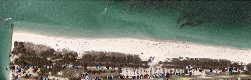

77
78 THIS BORING LOG IS NOT VALID IF SEPARATED FROM ORIGINAL REPORT. GEO SMART LOG-NO WELL HC1032.COQUINABEACHDRAINAGEIMPROVEMENTS.GPJ TERRACON201.GDT 12/4/1 PROJECT: Coquina Beach Drainage Improvements SITE: GRAPHIC LOG LOCATION DEPTH SLIGHTLY SILTY SAND (SP-SM), trace to some shell fragments, fine grained, light brown to light gray, medium dense to very dense.0 Boring Terminated at Feet Stratification lines are approximate. In-situ, the transition may be gradual. Advancement Method: Mud Rotary 261 Gulf Drive Bradenton Beach, Florida See Exhibit A-4 Latitude: Longitude: Abandonment Method: Borings backfilled with soil cuttings upon completion. WATER LEVEL OBSERVATIONS Groundwater initally observed at a depth of feet bgs BORING LOG NO. B-1 See Exhibit A- for description of field procedures See Appendix B for description of laboratory procedures and additional data (if any). -6. See Appendix C for explanation of symbols and abbreviations Vico Court, Unit B Sarasota, Florida N= N= N= N= N=3 Hammer Type: Rope and Cathead Notes: Boring Started: 11/13/201 Drill Rig: BR200 Project No.: HC1032 Page 1 of 1 Manatee County Construction Services Division CLIENT: Bradenton, Florida Surface Elev.: 3.7 (Ft.) ELEVATION (Ft.) DEPTH (Ft.) WATER LEVEL OBSERVATIONS SAMPLE TYPE FIELD TEST RESULTS Boring Completed: 11/13/201 Driller: JM ORGANIC Exhibit: A-6 WATER PERCENT FINES
79 THIS BORING LOG IS NOT VALID IF SEPARATED FROM ORIGINAL REPORT. GEO SMART LOG-NO WELL HC1032.COQUINABEACHDRAINAGEIMPROVEMENTS.GPJ TERRACON201.GDT 12/4/1 PROJECT: Coquina Beach Drainage Improvements SITE: GRAPHIC LOG LOCATION DEPTH ELEVATION (Ft.) SLIGHTLY SILTY SAND (SP-SM), trace shell fragments, fine grained, light gray to gray, medium dense to dense 2.0 Boring Terminated at 2 Feet Stratification lines are approximate. In-situ, the transition may be gradual. Advancement Method: Mud Rotary 261 Gulf Drive Bradenton Beach, Florida See Exhibit A-4 Latitude: Longitude: Abandonment Method: Borings backfilled with soil cuttings upon completion. WATER LEVEL OBSERVATIONS Groundwater initally observed at a depth of feet bgs BORING LOG NO. B-2 See Exhibit A- for description of field procedures See Appendix B for description of laboratory procedures and additional data (if any) See Appendix C for explanation of symbols and abbreviations Vico Court, Unit B Sarasota, Florida N= N= N= N= N= N= N= N=46 Hammer Type: Rope and Cathead Notes: Boring Started: 11/13/201 Drill Rig: BR200 Project No.: HC1032 Page 1 of 1 Manatee County Construction Services Division CLIENT: Bradenton, Florida Surface Elev.: 3. (Ft.) DEPTH (Ft.) WATER LEVEL OBSERVATIONS SAMPLE TYPE FIELD TEST RESULTS Boring Completed: 11/13/201 Driller: JM ORGANIC Exhibit: A-7 WATER PERCENT FINES
80 THIS BORING LOG IS NOT VALID IF SEPARATED FROM ORIGINAL REPORT. GEO SMART LOG-NO WELL HC1032.COQUINABEACHDRAINAGEIMPROVEMENTS.GPJ TERRACON201.GDT 12/4/1 PROJECT: Coquina Beach Drainage Improvements SITE: GRAPHIC LOG LOCATION DEPTH SLIGHTLY SILTY SAND (SP-SM), trace to some shell fragments, fine grained, light brown to gray, medium dense to very dense.0 Boring Terminated at Feet Stratification lines are approximate. In-situ, the transition may be gradual. Advancement Method: Mud Rotary 261 Gulf Drive Bradenton Beach, Florida See Exhibit A-4 Latitude: Longitude: Abandonment Method: Borings backfilled with soil cuttings upon completion. WATER LEVEL OBSERVATIONS Groundwater initally observed at a depth of feet bgs BORING LOG NO. B-3 See Exhibit A- for description of field procedures See Appendix B for description of laboratory procedures and additional data (if any). See Appendix C for explanation of symbols and abbreviations Vico Court, Unit B Sarasota, Florida N= N= N= N= N=3 Hammer Type: Rope and Cathead Notes: Boring Started: 11/13/201 Drill Rig: BR200 Project No.: HC1032 Page 1 of 1 Manatee County Construction Services Division CLIENT: Bradenton, Florida Surface Elev.: 2.8 (Ft.) ELEVATION (Ft.) DEPTH (Ft.) WATER LEVEL OBSERVATIONS SAMPLE TYPE FIELD TEST RESULTS Boring Completed: 11/13/201 Driller: JM ORGANIC Exhibit: A-8 WATER PERCENT FINES
81 THIS BORING LOG IS NOT VALID IF SEPARATED FROM ORIGINAL REPORT. GEO SMART LOG-NO WELL HC1032.COQUINABEACHDRAINAGEIMPROVEMENTS.GPJ TERRACON201.GDT 12/4/1 PROJECT: Coquina Beach Drainage Improvements SITE: GRAPHIC LOG LOCATION DEPTH ELEVATION (Ft.) SLIGHTLY SILTY SAND (SP-SM), trace shell fragments, fine grained, light brown to gray, medium dense to dense 2.0 Boring Terminated at 2 Feet Stratification lines are approximate. In-situ, the transition may be gradual. Advancement Method: Mud Rotary 261 Gulf Drive Bradenton Beach, Florida See Exhibit A-4 Latitude: Longitude: Abandonment Method: Borings backfilled with soil cuttings upon completion. WATER LEVEL OBSERVATIONS Groundwater initally observed at a depth of feet bgs BORING LOG NO. B-4 See Exhibit A- for description of field procedures See Appendix B for description of laboratory procedures and additional data (if any) See Appendix C for explanation of symbols and abbreviations Vico Court, Unit B Sarasota, Florida N= N= N= N= N= N= N= N=40 Hammer Type: Rope and Cathead Notes: Boring Started: 11/13/201 Drill Rig: BR200 Project No.: HC1032 Page 1 of 1 Manatee County Construction Services Division CLIENT: Bradenton, Florida Surface Elev.: 3.4 (Ft.) DEPTH (Ft.) WATER LEVEL OBSERVATIONS SAMPLE TYPE FIELD TEST RESULTS Driller: JM ORGANIC 22 9 Boring Completed: 11/13/201 Exhibit: A-9 WATER PERCENT FINES
82 THIS BORING LOG IS NOT VALID IF SEPARATED FROM ORIGINAL REPORT. GEO SMART LOG-NO WELL HC1032.COQUINABEACHDRAINAGEIMPROVEMENTS.GPJ TERRACON201.GDT 12/4/1 PROJECT: Coquina Beach Drainage Improvements SITE: GRAPHIC LOG LOCATION DEPTH ELEVATION (Ft.) SLIGHTLY SILTY SAND (SP-SM), trace shell fragments, fine grained, light gray to gray, medium dense to dense.0 Boring Terminated at Feet Stratification lines are approximate. In-situ, the transition may be gradual. Advancement Method: Mud Rotary 261 Gulf Drive Bradenton Beach, Florida See Exhibit A-4 Latitude: Longitude: Abandonment Method: Borings backfilled with soil cuttings upon completion. WATER LEVEL OBSERVATIONS Groundwater initally observed at a depth of feet bgs BORING LOG NO. B- See Exhibit A- for description of field procedures See Appendix B for description of laboratory procedures and additional data (if any). See Appendix C for explanation of symbols and abbreviations Vico Court, Unit B Sarasota, Florida N= N= N= N= N=43 Hammer Type: Rope and Cathead Notes: Boring Started: 11/13/201 Drill Rig: BR200 Project No.: HC1032 Page 1 of 1 Manatee County Construction Services Division CLIENT: Bradenton, Florida Surface Elev.: 3.1 (Ft.) DEPTH (Ft.) WATER LEVEL OBSERVATIONS SAMPLE TYPE FIELD TEST RESULTS Boring Completed: 11/13/201 Driller: JM ORGANIC Exhibit: A- WATER PERCENT FINES
83 THIS BORING LOG IS NOT VALID IF SEPARATED FROM ORIGINAL REPORT. GEO SMART LOG-NO WELL HC1032.COQUINABEACHDRAINAGEIMPROVEMENTS.GPJ TERRACON201.GDT 12/4/1 PROJECT: Coquina Beach Drainage Improvements SITE: GRAPHIC LOG LOCATION DEPTH SLIGHTLY SILTY SAND (SP-SM), trace to some shell fragments, fine grained, light brown and light gray to gray, loose to dense 2.0 Boring Terminated at 2 Feet Stratification lines are approximate. In-situ, the transition may be gradual. Advancement Method: Mud Rotary 261 Gulf Drive Bradenton Beach, Florida See Exhibit A-4 Latitude: Longitude: Abandonment Method: Borings backfilled with soil cuttings upon completion. WATER LEVEL OBSERVATIONS Groundwater initally observed at a depth of feet bgs BORING LOG NO. B-6 See Exhibit A- for description of field procedures See Appendix B for description of laboratory procedures and additional data (if any). -22 See Appendix C for explanation of symbols and abbreviations Vico Court, Unit B Sarasota, Florida N= N= N= N= N= N= N= N=41 Hammer Type: Rope and Cathead Notes: Boring Started: 11/13/201 Drill Rig: BR200 Project No.: HC1032 Page 1 of 1 Manatee County Construction Services Division CLIENT: Bradenton, Florida Surface Elev.: 2.8 (Ft.) ELEVATION (Ft.) DEPTH (Ft.) WATER LEVEL OBSERVATIONS SAMPLE TYPE FIELD TEST RESULTS Boring Completed: 11/13/201 Driller: JM ORGANIC Exhibit: A-11 WATER PERCENT FINES
84 THIS BORING LOG IS NOT VALID IF SEPARATED FROM ORIGINAL REPORT. GEO SMART LOG-NO WELL HC1032.COQUINABEACHDRAINAGEIMPROVEMENTS.GPJ TERRACON201.GDT 12/4/1 PROJECT: Coquina Beach Drainage Improvements SITE: GRAPHIC LOG LOCATION DEPTH SLIGHTLY SILTY SAND (SP-SM), trace to some shell fragments, fine grained, light gray to light brown, medium dense to dense.0 Boring Terminated at Feet Stratification lines are approximate. In-situ, the transition may be gradual. Advancement Method: Mud Rotary 261 Gulf Drive Bradenton Beach, Florida See Exhibit A-4 Latitude: Longitude: Abandonment Method: Borings backfilled with soil cuttings upon completion. WATER LEVEL OBSERVATIONS Groundwater initally observed at a depth of feet bgs BORING LOG NO. B-7 See Exhibit A- for description of field procedures See Appendix B for description of laboratory procedures and additional data (if any). See Appendix C for explanation of symbols and abbreviations Vico Court, Unit B Sarasota, Florida N= N= N= N= N=13 Hammer Type: Rope and Cathead Notes: Boring Started: 11/13/201 Drill Rig: BR200 Project No.: HC1032 Page 1 of 1 Manatee County Construction Services Division CLIENT: Bradenton, Florida Surface Elev.: 3.1 (Ft.) ELEVATION (Ft.) DEPTH (Ft.) WATER LEVEL OBSERVATIONS SAMPLE TYPE FIELD TEST RESULTS Boring Completed: 11/13/201 Driller: JM ORGANIC Exhibit: A-12 WATER PERCENT FINES
85 THIS BORING LOG IS NOT VALID IF SEPARATED FROM ORIGINAL REPORT. GEO SMART LOG-NO WELL HC1032.COQUINABEACHDRAINAGEIMPROVEMENTS.GPJ TERRACON201.GDT 12/4/1 PROJECT: Coquina Beach Drainage Improvements SITE: GRAPHIC LOG LOCATION DEPTH ELEVATION (Ft.) SLIGHTLY SILTY SAND (SP-SM), trace shell fragments, fine grained, light gray to gray, loose to dense 2.0 Boring Terminated at 2 Feet Stratification lines are approximate. In-situ, the transition may be gradual. Advancement Method: Mud Rotary 261 Gulf Drive Bradenton Beach, Florida See Exhibit A-4 Latitude: Longitude: Abandonment Method: Borings backfilled with soil cuttings upon completion. WATER LEVEL OBSERVATIONS Groundwater initally observed at a depth of feet bgs BORING LOG NO. B-8 See Exhibit A- for description of field procedures See Appendix B for description of laboratory procedures and additional data (if any). -22 See Appendix C for explanation of symbols and abbreviations Vico Court, Unit B Sarasota, Florida N= N= N= N= N= N= N= N=41 Hammer Type: Rope and Cathead Notes: Boring Started: 11/13/201 Drill Rig: BR200 Project No.: HC1032 Page 1 of 1 Manatee County Construction Services Division CLIENT: Bradenton, Florida Surface Elev.: 3.2 (Ft.) DEPTH (Ft.) WATER LEVEL OBSERVATIONS SAMPLE TYPE FIELD TEST RESULTS Boring Completed: 11/13/201 Driller: JM ORGANIC Exhibit: A-13 WATER PERCENT FINES
86 THIS BORING LOG IS NOT VALID IF SEPARATED FROM ORIGINAL REPORT. GEO SMART LOG-NO WELL HC1032.COQUINABEACHDRAINAGEIMPROVEMENTS.GPJ TERRACON201.GDT 12/4/1 PROJECT: Coquina Beach Drainage Improvements SITE: GRAPHIC LOG LOCATION DEPTH ELEVATION (Ft.) SLIGHTLY SILTY SAND (SP-SM), with shell fragements, fine grained, dark gray, medium dense 2.0 SLIGHTLY SILTY SAND (SP-SM), trace shell fragments, fine grained, light gray, medium dense to very dense.0 Boring Terminated at Feet Stratification lines are approximate. In-situ, the transition may be gradual. Advancement Method: Mud Rotary 261 Gulf Drive Bradenton Beach, Florida See Exhibit A-4 Latitude: Longitude: Abandonment Method: Borings backfilled with soil cuttings upon completion. WATER LEVEL OBSERVATIONS Groundwater initally observed at a depth of feet bgs BORING LOG NO. B-9 See Exhibit A- for description of field procedures See Appendix B for description of laboratory procedures and additional data (if any) See Appendix C for explanation of symbols and abbreviations Vico Court, Unit B Sarasota, Florida N= N= N= N= N=36 Hammer Type: Rope and Cathead Notes: Boring Started: 11/13/201 Drill Rig: BR200 Project No.: HC1032 Page 1 of 1 Manatee County Construction Services Division CLIENT: Bradenton, Florida Surface Elev.: 3.4 (Ft.) DEPTH (Ft.) WATER LEVEL OBSERVATIONS SAMPLE TYPE FIELD TEST RESULTS Boring Completed: 11/13/201 Driller: JM ORGANIC Exhibit: A-14 WATER PERCENT FINES
87 THIS BORING LOG IS NOT VALID IF SEPARATED FROM ORIGINAL REPORT. GEO SMART LOG-NO WELL HC1032.COQUINABEACHDRAINAGEIMPROVEMENTS.GPJ TERRACON201.GDT 12/4/1 PROJECT: Coquina Beach Drainage Improvements SITE: GRAPHIC LOG LOCATION DEPTH SLIGHTLY SILTY SAND (SP-SM), trace to some shell fragments, fine grained, light brown to dark gray and gray, loose to medium dense 2.0 Boring Terminated at 2 Feet Stratification lines are approximate. In-situ, the transition may be gradual. Advancement Method: Mud Rotary 261 Gulf Drive Bradenton Beach, Florida See Exhibit A-4 Latitude: Longitude: Abandonment Method: Borings backfilled with soil cuttings upon completion. WATER LEVEL OBSERVATIONS Groundwater initally observed at a depth of feet bgs BORING LOG NO. B- See Exhibit A- for description of field procedures See Appendix B for description of laboratory procedures and additional data (if any) See Appendix C for explanation of symbols and abbreviations Vico Court, Unit B Sarasota, Florida N= N= N= N= N= N=9-7-9 N= N=1 Hammer Type: Rope and Cathead Notes: Boring Started: 11/13/201 Drill Rig: BR200 Project No.: HC1032 Page 1 of 1 Manatee County Construction Services Division CLIENT: Bradenton, Florida Surface Elev.: 3.7 (Ft.) ELEVATION (Ft.) DEPTH (Ft.) WATER LEVEL OBSERVATIONS SAMPLE TYPE FIELD TEST RESULTS Boring Completed: 11/13/201 Driller: JM ORGANIC Exhibit: A-1 WATER PERCENT FINES
88 THIS BORING LOG IS NOT VALID IF SEPARATED FROM ORIGINAL REPORT. GEO SMART LOG-NO WELL HC1032.COQUINABEACHDRAINAGEIMPROVEMENTS.GPJ TERRACON201.GDT 12/4/1 PROJECT: Coquina Beach Drainage Improvements SITE: GRAPHIC LOG LOCATION DEPTH ELEVATION (Ft.) SLIGHTLY SILTY SAND (SP-SM), some shell fragments, fine grained, light brown to light gray and gray, loose to medium dense.0 Boring Terminated at Feet Stratification lines are approximate. In-situ, the transition may be gradual. Advancement Method: Mud Rotary 261 Gulf Drive Bradenton Beach, Florida See Exhibit A-4 Latitude: Longitude: Abandonment Method: Borings backfilled with soil cuttings upon completion. WATER LEVEL OBSERVATIONS Groundwater initally observed at a depth of feet bgs BORING LOG NO. B-11 See Exhibit A- for description of field procedures See Appendix B for description of laboratory procedures and additional data (if any). -. See Appendix C for explanation of symbols and abbreviations Vico Court, Unit B Sarasota, Florida N= N= N= N= N=16 Hammer Type: Rope and Cathead Notes: Boring Started: 11/16/201 Drill Rig: BR200 Project No.: HC1032 Page 1 of 1 Manatee County Construction Services Division CLIENT: Bradenton, Florida Surface Elev.: 4.6 (Ft.) DEPTH (Ft.) WATER LEVEL OBSERVATIONS SAMPLE TYPE FIELD TEST RESULTS Boring Completed: 11/16/201 Driller: JM ORGANIC Exhibit: A-16 WATER PERCENT FINES
89 THIS BORING LOG IS NOT VALID IF SEPARATED FROM ORIGINAL REPORT. GEO SMART LOG-NO WELL HC1032.COQUINABEACHDRAINAGEIMPROVEMENTS.GPJ TERRACON201.GDT 12/4/1 PROJECT: Coquina Beach Drainage Improvements SITE: GRAPHIC LOG LOCATION DEPTH SLIGHTLY SILTY SAND (SP-SM), trace to some shell fragments, fine grained, light brown to light gray, medium dense to dense 2.0 Boring Terminated at 2 Feet Stratification lines are approximate. In-situ, the transition may be gradual. Advancement Method: Mud Rotary 261 Gulf Drive Bradenton Beach, Florida See Exhibit A-4 Latitude: Longitude: Abandonment Method: Borings backfilled with soil cuttings upon completion. WATER LEVEL OBSERVATIONS Groundwater initally observed at a depth of 8 feet bgs BORING LOG NO. B-12 See Exhibit A- for description of field procedures See Appendix B for description of laboratory procedures and additional data (if any) See Appendix C for explanation of symbols and abbreviations Vico Court, Unit B Sarasota, Florida N= N= N= N= N= N= N= N=14 Hammer Type: Rope and Cathead Notes: Boring Started: 11/11/201 Drill Rig: BR200 Project No.: HC1032 Page 1 of 1 Manatee County Construction Services Division CLIENT: Bradenton, Florida Surface Elev.: 3.6 (Ft.) ELEVATION (Ft.) DEPTH (Ft.) WATER LEVEL OBSERVATIONS SAMPLE TYPE FIELD TEST RESULTS Driller: MF ORGANIC Boring Completed: 11/11/201 Exhibit: A-17 WATER PERCENT FINES
90 THIS BORING LOG IS NOT VALID IF SEPARATED FROM ORIGINAL REPORT. GEO SMART LOG-NO WELL HC1032.COQUINABEACHDRAINAGEIMPROVEMENTS.GPJ TERRACON201.GDT 12/4/1 PROJECT: Coquina Beach Drainage Improvements SITE: GRAPHIC LOG LOCATION SLIGHTLY SILTY SAND (SP-SM), large tree debris, fine grained, gray, medium dense SLIGHTLY SILTY SAND (SP-SM), fine grained, light gray to gray, loose to medium dense.0 Boring Terminated at Feet Stratification lines are approximate. In-situ, the transition may be gradual. Advancement Method: Mud Rotary 261 Gulf Drive Bradenton Beach, Florida See Exhibit A-4 Latitude: Longitude: Abandonment Method: Borings backfilled with soil cuttings upon completion. BORING LOG NO. B-13 See Exhibit A- for description of field procedures See Appendix B for description of laboratory procedures and additional data (if any) See Appendix C for explanation of symbols and abbreviations Vico Court, Unit B Sarasota, Florida N= N= N= N= N=7 Hammer Type: Rope and Cathead Notes: Boring Started: 11/16/201 Drill Rig: BR200 Project No.: HC1032 Page 1 of 1 Manatee County Construction Services Division CLIENT: Bradenton, Florida Surface Elev.: 3.7 (Ft.) DEPTH ELEVATION (Ft.) SLIGHTLY SILTY SAND (SP-SM), some shell fragments, fine grained, brown, medium dense WATER LEVEL OBSERVATIONS Groundwater initally observed at a depth of feet bgs DEPTH (Ft.) WATER LEVEL OBSERVATIONS SAMPLE TYPE FIELD TEST RESULTS Boring Completed: 11/16/201 Driller: JM ORGANIC Exhibit: A-18 WATER PERCENT FINES
91 THIS BORING LOG IS NOT VALID IF SEPARATED FROM ORIGINAL REPORT. GEO SMART LOG-NO WELL HC1032.COQUINABEACHDRAINAGEIMPROVEMENTS.GPJ TERRACON201.GDT 12/4/1 PROJECT: Coquina Beach Drainage Improvements SITE: GRAPHIC LOG LOCATION DEPTH ELEVATION (Ft.) SLIGHTLY SILTY SAND (SP-SM), with shell fragments, fine grained, 1.0 brown, medium dense SLIGHTLY SILTY SAND (SP-SM), organic stained, fine grained, black, medium dense 2 SLIGHTLY SILTY SAND (SP-SM), trace to some shell fragments, fine grained, light gray to gray, medium dense 2.0 Boring Terminated at 2 Feet Stratification lines are approximate. In-situ, the transition may be gradual. Advancement Method: Mud Rotary 261 Gulf Drive Bradenton Beach, Florida See Exhibit A-4 Latitude: Longitude: Abandonment Method: Borings backfilled with soil cuttings upon completion. WATER LEVEL OBSERVATIONS Groundwater initally observed at a depth of feet bgs BORING LOG NO. B-14 See Exhibit A- for description of field procedures See Appendix B for description of laboratory procedures and additional data (if any). See Appendix C for explanation of symbols and abbreviations Vico Court, Unit B Sarasota, Florida N= N= N= N= N= N= N= N=2 Hammer Type: Rope and Cathead Notes: Boring Started: 11/16/201 Drill Rig: BR200 Project No.: HC1032 Page 1 of 1 Manatee County Construction Services Division CLIENT: Bradenton, Florida Surface Elev.: 4.1 (Ft.) DEPTH (Ft.) WATER LEVEL OBSERVATIONS SAMPLE TYPE FIELD TEST RESULTS Driller: JM ORGANIC Boring Completed: 11/16/201 Exhibit: A-19 WATER PERCENT FINES
92 THIS BORING LOG IS NOT VALID IF SEPARATED FROM ORIGINAL REPORT. GEO SMART LOG-NO WELL HC1032.COQUINABEACHDRAINAGEIMPROVEMENTS.GPJ TERRACON201.GDT 12/4/1 PROJECT: Coquina Beach Drainage Improvements SITE: GRAPHIC LOG LOCATION.0 Boring Terminated at Feet Stratification lines are approximate. In-situ, the transition may be gradual. Advancement Method: Mud Rotary 261 Gulf Drive Bradenton Beach, Florida See Exhibit A-4 Latitude: Longitude: Abandonment Method: Borings backfilled with soil cuttings upon completion. BORING LOG NO. B-1 See Exhibit A- for description of field procedures See Appendix B for description of laboratory procedures and additional data (if any). See Appendix C for explanation of symbols and abbreviations Vico Court, Unit B Sarasota, Florida N= N= N= N= N=21 Hammer Type: Rope and Cathead Notes: Boring Started: 11/16/201 Drill Rig: BR200 Project No.: HC1032 Page 1 of 1 Manatee County Construction Services Division CLIENT: Bradenton, Florida Surface Elev.: 4.9 (Ft.) DEPTH ELEVATION (Ft.) SLIGHTLY SILTY SAND (SP-SM), trace to some shell fragments, fine grained, brown to light gray and gray, loose to medium dense WATER LEVEL OBSERVATIONS Groundwater initally observed at a depth of feet bgs DEPTH (Ft.) WATER LEVEL OBSERVATIONS SAMPLE TYPE FIELD TEST RESULTS Boring Completed: 11/16/201 Driller: JM ORGANIC Exhibit: A-20 WATER PERCENT FINES
93 THIS BORING LOG IS NOT VALID IF SEPARATED FROM ORIGINAL REPORT. GEO SMART LOG-NO WELL HC1032.COQUINABEACHDRAINAGEIMPROVEMENTS.GPJ TERRACON201.GDT 12/4/1 PROJECT: Coquina Beach Drainage Improvements SITE: GRAPHIC LOG LOCATION DEPTH SLIGHTLY SILTY SAND (SP-SM), with shell fragments, fine grained, brown to light gray and light brown, medium dense ORGANIC SAND (SP-SM, PT), fine grained, gray and black, loose SLIGHTLY SILTY SAND (SP-SM), trace shell fragments, fine grained, light gray to gray, medium dense to dense 2.0 Boring Terminated at 2 Feet Stratification lines are approximate. In-situ, the transition may be gradual. Advancement Method: Mud Rotary 261 Gulf Drive Bradenton Beach, Florida See Exhibit A-4 Latitude: Longitude: Abandonment Method: Borings backfilled with soil cuttings upon completion. WATER LEVEL OBSERVATIONS Groundwater initally observed at a depth of feet bgs BORING LOG NO. B-16 See Exhibit A- for description of field procedures See Appendix B for description of laboratory procedures and additional data (if any) See Appendix C for explanation of symbols and abbreviations Vico Court, Unit B Sarasota, Florida N= N= N= N= N= N=26-7- N= N=28 Hammer Type: Rope and Cathead Notes: Boring Started: 11/16/201 Drill Rig: BR200 Project No.: HC1032 Page 1 of 1 Manatee County Construction Services Division CLIENT: Bradenton, Florida Surface Elev.: 3.7 (Ft.) ELEVATION (Ft.) DEPTH (Ft.) WATER LEVEL OBSERVATIONS SAMPLE TYPE FIELD TEST RESULTS Driller: JM ORGANIC Boring Completed: 11/16/201 Exhibit: A-21 WATER PERCENT FINES
94 THIS BORING LOG IS NOT VALID IF SEPARATED FROM ORIGINAL REPORT. GEO SMART LOG-NO WELL HC1032.COQUINABEACHDRAINAGEIMPROVEMENTS.GPJ TERRACON201.GDT 12/4/1 PROJECT: Coquina Beach Drainage Improvements SITE: GRAPHIC LOG LOCATION DEPTH ELEVATION (Ft.) ORGANIC SAND (SP-SM, PT), fine grained, dark gray, medium dense to 1.0 dense SLIGHTLY SILTY SAND (SP-SM), fine grained, light gray, medium dense ORGANIC SAND (SP-SM, PT), tree debris, fine grained, dark brown to dark gray, very loose SLIGHTLY SILTY SAND (SP-SM), trace shell fragments, fine grained, light gray, medium dense.0 Boring Terminated at Feet Stratification lines are approximate. In-situ, the transition may be gradual. Advancement Method: Mud Rotary 261 Gulf Drive Bradenton Beach, Florida See Exhibit A-4 Latitude: Longitude: Abandonment Method: Borings backfilled with soil cuttings upon completion. WATER LEVEL OBSERVATIONS Groundwater initally observed at a depth of feet bgs BORING LOG NO. B-17 See Exhibit A- for description of field procedures See Appendix B for description of laboratory procedures and additional data (if any). See Appendix C for explanation of symbols and abbreviations Vico Court, Unit B Sarasota, Florida N= N= N= N= N=16 Hammer Type: Rope and Cathead Notes: Boring Started: 11/16/201 Drill Rig: BR200 Project No.: HC1032 Page 1 of 1 Manatee County Construction Services Division CLIENT: Bradenton, Florida Surface Elev.: 6.2 (Ft.) DEPTH (Ft.) WATER LEVEL OBSERVATIONS SAMPLE TYPE FIELD TEST RESULTS Driller: JM ORGANIC 7. 8 Boring Completed: 11/16/201 Exhibit: A-22 WATER PERCENT FINES
95 THIS BORING LOG IS NOT VALID IF SEPARATED FROM ORIGINAL REPORT. GEO SMART LOG-NO WELL HC1032.COQUINABEACHDRAINAGEIMPROVEMENTS.GPJ TERRACON201.GDT 12/4/1 PROJECT: Coquina Beach Drainage Improvements SITE: GRAPHIC LOG LOCATION DEPTH ELEVATION (Ft.) SLIGHTLY SILTY SAND (SP-SM), trace to some shell fragments, fine grained, light gray and light brown to dark brown and dark gray, medium dense to dense 2.0 Boring Terminated at 2 Feet Stratification lines are approximate. In-situ, the transition may be gradual. Advancement Method: Mud Rotary 261 Gulf Drive Bradenton Beach, Florida See Exhibit A-4 Latitude: Longitude: Abandonment Method: Borings backfilled with soil cuttings upon completion. WATER LEVEL OBSERVATIONS Groundwater initally observed at a depth of feet bgs BORING LOG NO. B-18 See Exhibit A- for description of field procedures See Appendix B for description of laboratory procedures and additional data (if any). See Appendix C for explanation of symbols and abbreviations Vico Court, Unit B Sarasota, Florida N= N= N= N= N= N= N= N=16 Hammer Type: Rope and Cathead Notes: Boring Started: 11/16/201 Drill Rig: BR200 Project No.: HC1032 Page 1 of 1 Manatee County Construction Services Division CLIENT: Bradenton, Florida Surface Elev.:.2 (Ft.) DEPTH (Ft.) WATER LEVEL OBSERVATIONS SAMPLE TYPE FIELD TEST RESULTS Driller: MF ORGANIC 23 2 Boring Completed: 11/16/201 Exhibit: A-23 WATER PERCENT FINES
96 THIS BORING LOG IS NOT VALID IF SEPARATED FROM ORIGINAL REPORT. GEO SMART LOG-NO WELL HC1032.COQUINABEACHDRAINAGEIMPROVEMENTS.GPJ TERRACON201.GDT 12/4/1 PROJECT: Coquina Beach Drainage Improvements SITE: GRAPHIC LOG LOCATION DEPTH ELEVATION (Ft.) SLIGHTLY SILTY SAND (SP-SM), trace shell fragments, fine grained, light brown and light gray to gray and brown, medium dense to dense.0 Boring Terminated at Feet Stratification lines are approximate. In-situ, the transition may be gradual. Advancement Method: Mud Rotary 261 Gulf Drive Bradenton Beach, Florida See Exhibit A-4 Latitude: Longitude: Abandonment Method: Borings backfilled with soil cuttings upon completion. WATER LEVEL OBSERVATIONS Groundwater initally observed at a depth of feet bgs BORING LOG NO. B-19 See Exhibit A- for description of field procedures See Appendix B for description of laboratory procedures and additional data (if any). See Appendix C for explanation of symbols and abbreviations Vico Court, Unit B Sarasota, Florida N= N= N= N= N=23 Hammer Type: Rope and Cathead Notes: Boring Started: 11/16/201 Drill Rig: BR200 Project No.: HC1032 Page 1 of 1 Manatee County Construction Services Division CLIENT: Bradenton, Florida Surface Elev.:.1 (Ft.) DEPTH (Ft.) WATER LEVEL OBSERVATIONS SAMPLE TYPE FIELD TEST RESULTS Boring Completed: 11/16/201 Driller: MF ORGANIC Exhibit: A-24 WATER PERCENT FINES
97 THIS BORING LOG IS NOT VALID IF SEPARATED FROM ORIGINAL REPORT. GEO SMART LOG-NO WELL HC1032.COQUINABEACHDRAINAGEIMPROVEMENTS.GPJ TERRACON201.GDT 12/4/1 PROJECT: Coquina Beach Drainage Improvements SITE: GRAPHIC LOG LOCATION DEPTH SLIGHTLY SILTY SAND (SP-SM), with shell fragments, fine grained, orange and brown SLIGHTLY SILTY SAND (SP-SM), with shell fragments, fine grained, light gray to gray, medium dense ORGANIC SAND (SP-SM, PT), fine grained, black to gray, very loose SLIGHTLY SILTY SAND (SP-SM), fine grained, light gray to dark gray, loose to medium dense 2.0 Boring Terminated at 2 Feet Stratification lines are approximate. In-situ, the transition may be gradual. Advancement Method: Mud Rotary 261 Gulf Drive Bradenton Beach, Florida See Exhibit A-4 Latitude: Longitude: Abandonment Method: Borings backfilled with soil cuttings upon completion. WATER LEVEL OBSERVATIONS Groundwater initally observed at a depth of 4 feet bgs BORING LOG NO. B-20 See Exhibit A- for description of field procedures See Appendix B for description of laboratory procedures and additional data (if any) See Appendix C for explanation of symbols and abbreviations Vico Court, Unit B Sarasota, Florida N= N= N= N= N= N= Hammer Type: Rope and Cathead Notes: Boring Started: 11/11/201 Drill Rig: BR200 Project No.: HC1032 Page 1 of 1 Manatee County Construction Services Division CLIENT: Bradenton, Florida Surface Elev.:.4 (Ft.) ELEVATION (Ft.) DEPTH (Ft.) WATER LEVEL OBSERVATIONS SAMPLE TYPE FIELD TEST RESULTS Driller: MF ORGANIC Boring Completed: 11/11/201 Exhibit: A-2 WATER PERCENT FINES
98 THIS BORING LOG IS NOT VALID IF SEPARATED FROM ORIGINAL REPORT. GEO SMART LOG-NO WELL HC1032.COQUINABEACHDRAINAGEIMPROVEMENTS.GPJ TERRACON201.GDT 12/4/1 PROJECT: Coquina Beach Drainage Improvements SITE: GRAPHIC LOG LOCATION DEPTH SLIGHTLY SILTY SAND (SP-SM), with shell fragments, fine grained, orange and brown, dense 2.0 SLIGHTLY SILTY SAND (SP-SM), trace to some shell fragments, fine grained, light gray to gray, medium dense to dense.0 Boring Terminated at Feet Stratification lines are approximate. In-situ, the transition may be gradual. Advancement Method: Mud Rotary 261 Gulf Drive Bradenton Beach, Florida See Exhibit A-4 Latitude: Longitude: Abandonment Method: Borings backfilled with soil cuttings upon completion. WATER LEVEL OBSERVATIONS Groundwater initally observed at a depth of feet bgs BORING LOG NO. B-21 See Exhibit A- for description of field procedures See Appendix B for description of laboratory procedures and additional data (if any) See Appendix C for explanation of symbols and abbreviations Vico Court, Unit B Sarasota, Florida N= N= N= N= N=13 Hammer Type: Rope and Cathead Notes: Boring Started: 11/13/201 Drill Rig: BR200 Project No.: HC1032 Page 1 of 1 Manatee County Construction Services Division CLIENT: Bradenton, Florida Surface Elev.:.4 (Ft.) ELEVATION (Ft.) DEPTH (Ft.) WATER LEVEL OBSERVATIONS SAMPLE TYPE FIELD TEST RESULTS Boring Completed: 11/13/201 Driller: MF ORGANIC Exhibit: A-26 WATER PERCENT FINES
99 THIS BORING LOG IS NOT VALID IF SEPARATED FROM ORIGINAL REPORT. GEO SMART LOG-NO WELL HC1032.COQUINABEACHDRAINAGEIMPROVEMENTS.GPJ TERRACON201.GDT 12/4/1 PROJECT: Coquina Beach Drainage Improvements SITE: GRAPHIC LOG LOCATION DEPTH SLIGHTLY SILTY SAND (SP-SM), trace to some shell fragments, fine grained, light gray to brown, medium dense to dense 12. SILTY SAND (SM), fine grained, dark gray, very loose 17. SLIGHTLY SILTY SAND (SP-SM), fine grained, gray to dark gray, loose to medium dense 2.0 Boring Terminated at 2 Feet Stratification lines are approximate. In-situ, the transition may be gradual. Advancement Method: Mud Rotary 261 Gulf Drive Bradenton Beach, Florida See Exhibit A-4 Latitude: Longitude: Abandonment Method: Borings backfilled with soil cuttings upon completion. WATER LEVEL OBSERVATIONS Groundwater initally observed at a depth of feet bgs BORING LOG NO. B-22 See Exhibit A- for description of field procedures See Appendix B for description of laboratory procedures and additional data (if any) See Appendix C for explanation of symbols and abbreviations Vico Court, Unit B Sarasota, Florida N= N= N= N= N= N= N= N=19 Hammer Type: Rope and Cathead Notes: Boring Started: 11/13/201 Drill Rig: BR200 Project No.: HC1032 Page 1 of 1 Manatee County Construction Services Division CLIENT: Bradenton, Florida Surface Elev.:. (Ft.) ELEVATION (Ft.) DEPTH (Ft.) WATER LEVEL OBSERVATIONS SAMPLE TYPE FIELD TEST RESULTS Driller: MF ORGANIC 7 9 Boring Completed: 11/13/201 Exhibit: A-27 WATER PERCENT FINES
100 THIS BORING LOG IS NOT VALID IF SEPARATED FROM ORIGINAL REPORT. GEO SMART LOG-NO WELL HC1032.COQUINABEACHDRAINAGEIMPROVEMENTS.GPJ TERRACON201.GDT 12/4/1 PROJECT: Coquina Beach Drainage Improvements SITE: GRAPHIC LOG LOCATION DEPTH SLIGHTLY SILTY SAND (SP-SM), trace to some shell fragments, fine grained, light gray to gray and brown, loose to dense.0 Boring Terminated at Feet Stratification lines are approximate. In-situ, the transition may be gradual. Advancement Method: Mud Rotary 261 Gulf Drive Bradenton Beach, Florida See Exhibit A-4 Latitude: Longitude: Abandonment Method: Borings backfilled with soil cuttings upon completion. WATER LEVEL OBSERVATIONS Groundwater initally observed at a depth of feet bgs BORING LOG NO. B-23 See Exhibit A- for description of field procedures See Appendix B for description of laboratory procedures and additional data (if any). See Appendix C for explanation of symbols and abbreviations Vico Court, Unit B Sarasota, Florida N= N= N= N= N=8 Hammer Type: Rope and Cathead Notes: Boring Started: 11/13/201 Drill Rig: BR200 Project No.: HC1032 Page 1 of 1 Manatee County Construction Services Division CLIENT: Bradenton, Florida Surface Elev.:.9 (Ft.) ELEVATION (Ft.) DEPTH (Ft.) WATER LEVEL OBSERVATIONS SAMPLE TYPE FIELD TEST RESULTS Boring Completed: 11/13/201 Driller: MF ORGANIC Exhibit: A-28 WATER PERCENT FINES
101 THIS BORING LOG IS NOT VALID IF SEPARATED FROM ORIGINAL REPORT. GEO SMART LOG-NO WELL HC1032.COQUINABEACHDRAINAGEIMPROVEMENTS.GPJ TERRACON201.GDT 12/4/1 PROJECT: Coquina Beach Drainage Improvements SITE: GRAPHIC LOG LOCATION DEPTH SLIGHTLY SILTY SAND (SP-SM), trace to some shell fragments, fine grained, light gray to gray and brown, medium dense to very dense 2.0 Boring Terminated at 2 Feet Stratification lines are approximate. In-situ, the transition may be gradual. Advancement Method: Mud Rotary 261 Gulf Drive Bradenton Beach, Florida See Exhibit A-4 Latitude: Longitude: Abandonment Method: Borings backfilled with soil cuttings upon completion. WATER LEVEL OBSERVATIONS Groundwater initally observed at a depth of feet bgs BORING LOG NO. B-24 See Exhibit A- for description of field procedures See Appendix B for description of laboratory procedures and additional data (if any) See Appendix C for explanation of symbols and abbreviations Vico Court, Unit B Sarasota, Florida N= /4" N= N= N= N= N= N=17 Hammer Type: Rope and Cathead Notes: Boring Started: 11/13/201 Drill Rig: BR200 Project No.: HC1032 Page 1 of 1 Manatee County Construction Services Division CLIENT: Bradenton, Florida Surface Elev.:.6 (Ft.) ELEVATION (Ft.) DEPTH (Ft.) WATER LEVEL OBSERVATIONS SAMPLE TYPE FIELD TEST RESULTS Boring Completed: 11/13/201 Driller: MF ORGANIC Exhibit: A-29 WATER PERCENT FINES
102 THIS BORING LOG IS NOT VALID IF SEPARATED FROM ORIGINAL REPORT. GEO SMART LOG-NO WELL HC1032.COQUINABEACHDRAINAGEIMPROVEMENTS.GPJ TERRACON201.GDT 12/4/1 PROJECT: Coquina Beach Drainage Improvements SITE: GRAPHIC LOG LOCATION DEPTH SLIGHTLY SILTY SAND (SP-SM), trace to some shell fragments, fine grained, light gray to dark graay, loose to dense.0 Boring Terminated at Feet Stratification lines are approximate. In-situ, the transition may be gradual. Advancement Method: Mud Rotary 261 Gulf Drive Bradenton Beach, Florida See Exhibit A-4 Latitude: Longitude: Abandonment Method: Borings backfilled with soil cuttings upon completion. WATER LEVEL OBSERVATIONS Groundwater initally observed at a depth of feet bgs BORING LOG NO. B-2 See Exhibit A- for description of field procedures See Appendix B for description of laboratory procedures and additional data (if any). See Appendix C for explanation of symbols and abbreviations Vico Court, Unit B Sarasota, Florida N= N= N= N= N=22 Hammer Type: Rope and Cathead Notes: Boring Started: 11/13/201 Drill Rig: BR200 Project No.: HC1032 Page 1 of 1 Manatee County Construction Services Division CLIENT: Bradenton, Florida Surface Elev.:.2 (Ft.) ELEVATION (Ft.) DEPTH (Ft.) WATER LEVEL OBSERVATIONS SAMPLE TYPE FIELD TEST RESULTS Boring Completed: 11/13/201 Driller: MF ORGANIC Exhibit: A-30 WATER PERCENT FINES
103 THIS BORING LOG IS NOT VALID IF SEPARATED FROM ORIGINAL REPORT. GEO SMART LOG-NO WELL HC1032.COQUINABEACHDRAINAGEIMPROVEMENTS.GPJ TERRACON201.GDT 12/4/1 PROJECT: Coquina Beach Drainage Improvements SITE: GRAPHIC LOG LOCATION DEPTH SLIGHTLY SILTY SAND (SP-SM), fine grained, light gray to brown, medium dense SLIGHTLY SILTY SAND (SP-SM), large tree debris, fine grained, gray and brown, medium dense SLIGHTLY SILTY SAND (SP-SM), trace shell fragments, fine grained, light gray to dark brown, very loose to dense 2.0 Boring Terminated at 2 Feet Stratification lines are approximate. In-situ, the transition may be gradual. Advancement Method: Mud Rotary 261 Gulf Drive Bradenton Beach, Florida See Exhibit A-4 Latitude: Longitude: Abandonment Method: Borings backfilled with soil cuttings upon completion. WATER LEVEL OBSERVATIONS Groundwater initally observed at a depth of feet bgs BORING LOG NO. B-26 See Exhibit A- for description of field procedures See Appendix B for description of laboratory procedures and additional data (if any) See Appendix C for explanation of symbols and abbreviations Vico Court, Unit B Sarasota, Florida N= N= N= N= N= N= N= N=8 Hammer Type: Rope and Cathead Notes: Boring Started: 11/13/201 Drill Rig: BR200 Project No.: HC1032 Page 1 of 1 Manatee County Construction Services Division CLIENT: Bradenton, Florida Surface Elev.: 4.3 (Ft.) ELEVATION (Ft.) DEPTH (Ft.) WATER LEVEL OBSERVATIONS SAMPLE TYPE FIELD TEST RESULTS Boring Completed: 11/13/201 Driller: MF ORGANIC Exhibit: A-31 WATER PERCENT FINES
104 THIS BORING LOG IS NOT VALID IF SEPARATED FROM ORIGINAL REPORT. GEO SMART LOG-NO WELL HC1032.COQUINABEACHDRAINAGEIMPROVEMENTS.GPJ TERRACON201.GDT 12/4/1 PROJECT: Coquina Beach Drainage Improvements SITE: GRAPHIC LOG LOCATION DEPTH SLIGHTLY SILTY SAND (SP-SM), trace to some shell fragments, fine grained, light gray and light brown to gray, medium dense to dense.0 Boring Terminated at Feet Stratification lines are approximate. In-situ, the transition may be gradual. Advancement Method: Mud Rotary 261 Gulf Drive Bradenton Beach, Florida See Exhibit A-4 Latitude: Longitude: Abandonment Method: Borings backfilled with soil cuttings upon completion. WATER LEVEL OBSERVATIONS Groundwater initally observed at a depth of feet bgs BORING LOG NO. B-27 See Exhibit A- for description of field procedures See Appendix B for description of laboratory procedures and additional data (if any). -. See Appendix C for explanation of symbols and abbreviations Vico Court, Unit B Sarasota, Florida N= N= N= N= N=37 Hammer Type: Rope and Cathead Notes: Boring Started: 11/13/201 Drill Rig: BR200 Project No.: HC1032 Page 1 of 1 Manatee County Construction Services Division CLIENT: Bradenton, Florida Surface Elev.: 4. (Ft.) ELEVATION (Ft.) DEPTH (Ft.) WATER LEVEL OBSERVATIONS SAMPLE TYPE FIELD TEST RESULTS Boring Completed: 11/13/201 Driller: MF ORGANIC Exhibit: A-32 WATER PERCENT FINES
105 THIS BORING LOG IS NOT VALID IF SEPARATED FROM ORIGINAL REPORT. GEO SMART LOG-NO WELL HC1032.COQUINABEACHDRAINAGEIMPROVEMENTS.GPJ TERRACON201.GDT 12/4/1 PROJECT: Coquina Beach Drainage Improvements SITE: GRAPHIC LOG LOCATION DEPTH SLIGHTLY SILTY SAND (SP-SM), trace to some shell fragments, fine grained, light brown and light gray to gray, loose to medium dense 12. SILTY SAND (SM), fine grained, dark gray, very loose 17. SLIGHTLY SILTY SAND (SP-SM), trace to some shell fragments, fine grained, brown to gray, medium dense to dense 2.0 Boring Terminated at 2 Feet Stratification lines are approximate. In-situ, the transition may be gradual. Advancement Method: Mud Rotary 261 Gulf Drive Bradenton Beach, Florida See Exhibit A-4 Latitude: Longitude: Abandonment Method: Borings backfilled with soil cuttings upon completion. WATER LEVEL OBSERVATIONS Groundwater initally observed at a depth of feet bgs BORING LOG NO. B-28 See Exhibit A- for description of field procedures See Appendix B for description of laboratory procedures and additional data (if any) See Appendix C for explanation of symbols and abbreviations Vico Court, Unit B Sarasota, Florida N= N= N= N= N= N= N= N=37 Hammer Type: Rope and Cathead Notes: Boring Started: 11/13/201 Drill Rig: BR200 Project No.: HC1032 Page 1 of 1 Manatee County Construction Services Division CLIENT: Bradenton, Florida Surface Elev.: 4.7 (Ft.) ELEVATION (Ft.) DEPTH (Ft.) WATER LEVEL OBSERVATIONS SAMPLE TYPE FIELD TEST RESULTS Boring Completed: 11/13/201 Driller: MF ORGANIC Exhibit: A-33 WATER PERCENT FINES
106 THIS BORING LOG IS NOT VALID IF SEPARATED FROM ORIGINAL REPORT. GEO SMART LOG-NO WELL HC1032.COQUINABEACHDRAINAGEIMPROVEMENTS.GPJ TERRACON201.GDT 12/4/1 PROJECT: Coquina Beach Drainage Improvements SITE: GRAPHIC LOG LOCATION DEPTH SLIGHTLY SILTY SAND (SP-SM), trace to some shell fragments, fine grained, light gray to gray, very loose to very dense.0 Boring Terminated at Feet Stratification lines are approximate. In-situ, the transition may be gradual. Advancement Method: Mud Rotary 261 Gulf Drive Bradenton Beach, Florida See Exhibit A-4 Latitude: Longitude: Abandonment Method: Borings backfilled with soil cuttings upon completion. WATER LEVEL OBSERVATIONS Groundwater initally observed at a depth of feet bgs BORING LOG NO. B-29 See Exhibit A- for description of field procedures See Appendix B for description of laboratory procedures and additional data (if any). -. See Appendix C for explanation of symbols and abbreviations Vico Court, Unit B Sarasota, Florida N= N= N= N= N=4 Hammer Type: Rope and Cathead Notes: Boring Started: 11/13/201 Drill Rig: BR200 Project No.: HC1032 Page 1 of 1 Manatee County Construction Services Division CLIENT: Bradenton, Florida Surface Elev.: 4.7 (Ft.) ELEVATION (Ft.) DEPTH (Ft.) WATER LEVEL OBSERVATIONS SAMPLE TYPE FIELD TEST RESULTS Boring Completed: 11/13/201 Driller: MF ORGANIC Exhibit: A-34 WATER PERCENT FINES
107 THIS BORING LOG IS NOT VALID IF SEPARATED FROM ORIGINAL REPORT. GEO SMART LOG-NO WELL HC1032.COQUINABEACHDRAINAGEIMPROVEMENTS.GPJ TERRACON201.GDT 12/4/1 PROJECT: Coquina Beach Drainage Improvements SITE: GRAPHIC LOG LOCATION DEPTH SLIGHTLY SILTY SAND (SP-SM), trace to some shell fragments, fine grained, light brown to gray, dense SILTY SAND (SM), trace shell fragments, fine grained, gray, loose 17. SLIGHTLY SILTY SAND (SP-SM), organic staqined, fine grained, gray and black, loose SLIGHTLY SILTY SAND (SP-SM), trace to some shell fragments, fine grained, light gray to gray, loose to medium dense SLIGHTLY SILTY SAND (SP-SM), with shell fragments, fine grained, gray to dark gray, medium dense 2.0 Boring Terminated at 2 Feet Stratification lines are approximate. In-situ, the transition may be gradual. Advancement Method: Mud Rotary 261 Gulf Drive Bradenton Beach, Florida See Exhibit A-4 Latitude: Longitude: Abandonment Method: Borings backfilled with soil cuttings upon completion. WATER LEVEL OBSERVATIONS Groundwater initally observed at a depth of feet bgs BORING LOG NO. B-30 See Exhibit A- for description of field procedures See Appendix B for description of laboratory procedures and additional data (if any) See Appendix C for explanation of symbols and abbreviations Vico Court, Unit B Sarasota, Florida N= N= N= N= N= 8-- N= N=2 Hammer Type: Rope and Cathead Notes: Boring Started: 11/13/201 Drill Rig: BR200 Project No.: HC1032 Page 1 of 1 Manatee County Construction Services Division CLIENT: Bradenton, Florida Surface Elev.: 4.7 (Ft.) ELEVATION (Ft.) DEPTH (Ft.) WATER LEVEL OBSERVATIONS SAMPLE TYPE FIELD TEST RESULTS Driller: MF ORGANIC Boring Completed: 11/13/201 Exhibit: A-3 WATER PERCENT FINES
108 Table 2 - Hydraulic Conductivity and Infiltration Rate Test Results Location Horizontal Hydraulic Conductivity (ft/day) Vertical Hydraulic Conductivity (ft/day) Vertical Infiltration Rate (in/hr) BHP BHP BHP BHP DRI DRI DRI DRI
109 January 13, 2016 AEI Project No.: APGT TO: Dunkelberger Engineering and Testing 8260 Vico Court, Suite B Sarasota, Florida Attention: Mr. James Jackson SUBJECT: Spacing Recommendations for Proposed Underdrain System, Coquina Beach Improvements, Manatee County, Florida Dear Mr. Jackson: Andreyev Engineering, Inc. (AEI) has completed an evaluation in order to determine the adequate spacing for the proposed underdrain system. A spreadsheet was created to calculate the required spacing given the measured soil and aquifer parameters and the design information supplied by the client. The design spreadsheet is attached with this letter. Based on our calculations the underdrains should be spaced on 60 foot centers throughout the proposed pavement areas. These recommendations should be incorporated into the general recommendations provided in our original report. AEI appreciates the opportunity to participate in this project, and we trust that the information herein is sufficient for your design. If you have any questions or comments concerning the contents of this report, please do not hesitate to contact our office. Sincerely, ANDREYEV ENGINEERING, INC Jeffery E. Eller, P.E. Vice President Florida Registration No Attachment: Underdrain Calculations
110 UNDERDRAIN CALCULATIONS
111 UNDERDRAIN CALCULATIONS Coquina Beach Pervious Concrete - 1" Rain, 72 hr Recovery, factor of safety of 2 Project: Coquina Beach Pervious Concrete 1" Storm Recovery Project No: Location: ASSUMPTIONS: Largest area of pervious concrete 180 ft x 180 ft. 1" or rain to recover from top of concrete down to 1 foot below bottom of concrete slab in 36 hrs (72 hr/2 FS) Depth of Treatment Volume in Pond = ft Pond Freeboard = 0 ft Pipe Diameter = 6 inches = 0.00 ft Gravel Envelope on each side of pipes = 9 inches = 0.70 ft Minimum distance between Pond Bottom and top gravel envelope = 1.17 feet (m + r) Depth from natural ground to impermeable layer = 20 feet Area of Pond (from top of treatment volume) = ft 2 Max top dimension of pond perpendicular to pipes = 180 feet K (soil permbility rate) = 3 in/hr = 0.20 ft/hr = 6 ft/day Slope of Pipes = ft/ft = 0.20 % n = 0.2 Safety Factor = 2 "T" shaped drainage network. *DESIGN UNDERDRAIN TO LOWER WATER LEVEL TO A LEVEL 1' BELOW POND BOTTOM WITHIN 72 HOURS 1) Calculate the required drain spacing. d = Depth of Treatment Volume + Depth of Freeboard + Depth of Soil Between Pond Bottom/Envelope + Depth of Gravel Envelope + Drain Radius d = ft + 0 ft ft ft ft d = 2.20 ft Determine the height of the drain above the impermeable layer: a = D - d = 20 ft ft = ft Depth of Water Table after drawdown ( c ) = treatment volume depth + freeboard depth + ( r ) = (r = 6") c = ft + 0 ft ft = ft m = d - c = 2.20 ft ft = ft m 2 = ft 2 Determine the drainage coefficient (q) with t = 36hrs to incorporate a safety factor of 2. q = c / t = ft / 36 hr = ft/hr = in/hr Determine the Spacing (S) S = [(4 * K * (m * a * m)) / q] ^0. = 62 ft Determine the number of laterals (N) N > D PER / S = 3 2) Calculate the length of the Laterals. D PAR = A TL / D PER = ft 2 / 180 ft = ft Find the length of each lateral (L) L = 180 ft - 62 ft = 118 ft 3) Size the drainage laterals. Q r = [q * S * (L + S/2) / (C * F)] = cfs (Q 4"pipe) = 0.1 cfs 4) Size the main and outlet pipe. Flow in outlet = cfs/lateral * 62 laterals = 4. cfs (Q 1pipe) = 3.42 cfs
112 APPENDIX E TAYLOR ENGINEERING 30 YEAR EROSION PROJECTION LINE REPORT
113 December 17, 201 Mr. James M. Jackson, P.E. Dunkelberger Engineering and Testing 8260 Vico Ct., Unit B Sarasota, FL Re: Coquina Beach, Manatee County, Florida 30-year Erosion Projection Dear Mr. Jackson: This letter report details the methods and results of a historical beach recession analysis and estimate of the position of the Mean High Water (MHW) line 30 years from the present for an unprotected portion of Coquina Beach in Manatee County, Florida. Specifically, this report provides a site overview, tidal characteristics of the study area, procedures of the beach recession analysis, and a 30-year projection of the MHW shoreline. The 30-year shoreline projection follows the methodology defined by Rule 62B , Florida Administrative Code (F.A.C.). The report attachment contains all referenced figures. 1.0 Site Overview Coquina Beach lies on the Gulf of Mexico along the southern end of Anna Maria Island. At the southern end of Coquina Beach, Longboat Pass connects the Gulf of Mexico to the northern extent of Sarasota Bay. The Florida Department of Environmental Protection (FDEP) classifies the entire gulf shore of Anna Maria Island, including the study area, as a critically eroded shoreline. Figures 1 and2 illustrate the project location and the study area. The study area specifically encompasses the 0.9-mile stretch of beach between FDEP Manatee County Reference Monuments R-36 R-41 (Figure 2). As required by Rule 62B , F.A.C., 30-year Erosion Projection Procedures, Taylor Engineering analyzed shoreline changes at the monuments within the study area and at three adjacent monuments north of the study area (R-33 R-3). Table 1.1 lists the 2001 FDEP tabulated monument locations and profile azimuths associated with the historical shoreline surveys and analysis. Figure 2 shows the monument locations. 2.0 Tidal Characteristics To assess tidal characteristics at the site, Taylor Engineering reviewed National Oceanic and Atmospheric Administration (NOAA) tide station datums along the Gulf of Mexico nearest to the project site. NOAA Station (Anna Maria Outside) lies 3.6 miles north of the project site and Station (Casey Key) lies 21.1 miles south of the project site. Additionally, Taylor Engineering reviewed the datum from NOAA Station (Anna Maria City Pier), which lies within Tampa Bay approximately 6. miles north of the project site. Table 2.1 lists the tide datums of these stations D E E R W O O D P A R K B L V D B L D G S T E J A C K S O N V I L L E F L T E L W W W. T A Y L O R E N G I N E E R I N G. C O M
114 Mr. James M. Jackson, P.E. December 17, 201 Page 2 of 7 Table 1.1 Manatee County Reference Monument Locations FDEP Monument Adjacent Monuments Project Area Easting 1 (ft) Northing 1 (ft) Azimuth 2 ( N) R ,71.8 1,138, R , ,137, R-3 430, ,136, R ,6. 1,13, R , ,13, R , ,134, R , ,133, R , ,132, R , ,131, State Plane, Florida West Zone, North American Datum of 1983 (NAD83) 2 Degrees clockwise from north Tide Datum Table 2.1 Tide Datums near Project Site ANNA MARIA CITY PIER NOAA Station ANNA MARIA OUTSIDE NOAA Station CASEY KEY NOAA Station (ft-navd88) (ft-navd88) (ft-navd88) Mean Higher High Water (MHHW) Mean High Water (MHW) Mean Tide Level (MTL) Mean Low Water (MLW) Mean Lower Low Water (MLLW) Mean Tide Range This study adopted a MHW elevation of 0.34 ft-navd for the Coquina Beach study area based on NOAA Station (Anna Maria Outside). This station lies closest the project site and, with a slightly higher MHW, provides a more conservative MHW elevation compared to the other NOAA stations. Notably, MHW varies by less than two inches between all three tide stations. 3.0 FDEP 30-Year Erosion Analysis Procedure Taylor Engineering analyzed FDEP historical shoreline data, vetted the data for historic changes with morphological impact (e.g., beach nourishments and jetty construction), and derived shoreline change rates for each monument within the study area. Taylor Engineering analyzed 33 FDEP historical MHW shoreline positions dating from For quality assurance, Taylor Engineering plotted the positions over an aerial of the study area and processed historic surveys from the FDEP database to evaluate the accuracy of elevation and positions of
115 Mr. James M. Jackson, P.E. December 17, 201 Page 3 of 7 the historic MHW shoreline data. The survey data to shoreline data comparison revealed slight discrepancies in MHW position of approximately 1 2 feet. Table 3.1 lists the survey dates and respective ranges for each monument as provided by FDEP historic shoreline data. Figures 3 illustrate the August 1974, December 1992, February 2000, and February 2011 MHW shoreline positions with straight lines connecting shoreline positions at each monument. Throughout the 128-year analysis period, construction of the Longboat Pass jetties and beach nourishment affected the natural morphology of the study area. As illustrated in Figure 2, the northern jetty of Longboat Pass lies approximately 30 feet south of monument R-41. With littoral drift predominantly south to north along the gulf coast, the 197 construction of the Longboat Pass jetties (Dabees and Moore, 2011) significantly altered the morphological processes in the study area by introducing an up-drift littoral barrier (the jetty). Further, the 1960s construction of the Cortez Beach groins approximately 200 feet north of the study area (R-36), likely also influenced the local morphological processes at the northern end of the study area. Given that these activities significantly altered the local morphology, Taylor Engineering excluded surveys prior to 1964 from this analysis to ensure the present study only considered morphological processes relevant to the present study. The entire 7.-mile gulf shoreline of Anna Maria Island, including the study area, lies within the federal Anna Maria Island Shore Protection Project (SPP). The federal government originally authorized the SPP in 196, and has currently authorized it until 2043 (FDEP, 201). Through the SPP authorization, the U.S. Army Corps of Engineers (USACE) conducted large-scale beach nourishments along the central portion of Anna Maria Island (R-7 to R-36) in 1992/93 and 2002 which terminated at the northern limit of the study area (R-36). In 200, USACE conducted a smaller storm repair project within the central portion of the island. The proximity of these nourishments, along with analysis of the shoreline positions, indicates influence to the project area via longshore dispersal of the beach fill. More significantly, the 2011 Coquina Beach nourishment placed approximately 23,000 cubic yards (cy) within the study area, between monuments R-36 and R-41 (Hunsicker, et. al. 2013). Therefore, Taylor Engineering excluded the May 2011 survey from this analysis as it appears to describe the post-construction survey of the 2011 nourishment and does not represent background changes. Further, research indicated that in 2014, an additional nonfederal nourishment placed approximately 260,000 cy between R-33and R-40. (FDEP, 201). Analysis of data prior to the initial 1992 nourishment did not suggest clear historic trends in shoreline change and, because the current authorization of the SPP suggests perpetual nourishments within this area until 2043, Taylor Engineering primarily relied on survey data following the initial nourishment (i.e., during the 19- year period of December 1992 February 2011) to develop trends in shoreline change. To determine the historic shoreline change rate at each monument, Taylor Engineering applied both shoreline rate change averaging between surveys and conducted a linear regression analysis of the shoreline positions at each monument, striving to exclude outlying and inconsistent data points. Comparison of the shoreline change rates produced by the two analysis methods revealed that linear regression of the shoreline ranges provided the more reliable shoreline change rate estimates at each monument. 4.0 FDEP 30-year Erosion Projection Results Throughout the study area, Taylor Engineering found relatively uniform erosive shoreline change rates ranging between -1.8 and -2.8 feet/year. Within the project area, the resultant shoreline change rates compared conservatively to shoreline changes extrapolated by Absalonsen and Dean (20) for survey years Table 4.1 lists the shoreline change rates and the resultant 30-year erosion projections.
116 Mr. James M. Jackson, P.E. December 17, 201 Page 4 of 7 Survey Date Adjacent Monuments Table 3.1 Historic Monument Locations Range from Monument (ft) Project Area R-33 R-34 R-3 R-36 R-37 R-38 R-39 R-40 R August September December August October February May February June August August February March February February January May April September July May January December October February May
117 Mr. James M. Jackson, P.E. December 17, 201 Page of 7 Table 4.1 Shoreline Change Rates and Projections FDEP Monument Average Shoreline Change Rate 30-year Erosion Projection Adjacent Monuments Project Area (ft/yr) (ft from existing) R R R R R R R R R Taylor Engineering applied these rates to the February 2011 survey to project the 30-year erosion line. This survey provided the most recent available information prior to the 2011 Coquina Beach nourishment. For a conservative analysis, Taylor Engineering first projected erosion to present day (December 201), and subsequently developed the 30-year projection from the theoretical December 201 condition. Table 4.2 lists the 30-year (204) projected shoreline positions in State Plane Coordinates of the Florida West Zone, North American Datum of 1983 (NAD83). Figures 3 illustrate the projected shoreline over a 2013 aerial photograph. Table year Erosion Projected Shoreline Positions FDEP Monument Easting 1 (ft) Northing 1 (ft) Project Area R ,16.7 1,13,948.7 R , ,134,999.9 R , ,134,173.8 R ,31.8 1,133,29.2 R ,87.1 1,132,449.7 R ,028. 1,131, State Plane, Florida West Zone, North American Datum of 1983 (NAD83) 2 Degrees clockwise from north.0 Conclusion This letter report describes the 30-year erosion projection in accordance with Rule 62B , F.A.C., for Coquina Beach in Manatee County, Florida. Taylor Engineering performed an investigation of historic FDEP shoreline data and applied a linear regression analysis to determine shoreline change rates during an approximate 20-year duration with similar littoral processes to the existing conditions. Taylor
118
119 Mr. James M. Jackson, P.E. December 17, 201 Page 7 of 7 References Dabees, M.A. and B.D. Moore Inlet Evolution Modeling of Multiple Inlet Systems in Southwest and Central Florida, Journal of Coastal Research: Special Issue 9: pp Hunsicker, C.; R. Spadoni; T. Pierro; and L. Floyd Manatee County, Florida Board of County Commissioners Beach Renourishment Workshop Presentation. Florida Department of Environmental Protection (FDEP) Strategic Beach Management Plan Southwest Gulf Coast Region. Tallahassee, FL. Absalonsen, L. and R.G. Dean. 20. Characteristics of Shoreline Change along the Sandy Beaches of the State of Florida: An Atlas. Department of Civil and Coastal Engineering, University of Florida, Gainesville, FL.
120 ATTACHMENT Figures

121 DG Tampa Bay Anna Maria Island Gulf of Mexico DUNCAN GREER \\SJAX1\PROJECTS\201\C TERRACONCOQUINABEACHEROSIONLINE\DWG\COQUINALOCATION.DWG 12/17/201 11:43:27 AM N MANATEE COUNTY, FLORIDA 0 2 MILES 4 MILES SCALE: 1" = 2 MILES TAYLOR ENGINEERING INC. 11 DEERWOOD PARK BLVD. BLDG. 300, SUITE 300 JACKSONVILLE, FL 3226 CERTIFICATE OF AUTHORIZATION # 481 PROJECT AREA Longboat Pass Longboat Key FIGURE 1 LOCATION MAP COQUINA BEACH 30-YEAR EROSION PROJECTION MANATEE COUNTY, FL Bradenton PROJECT DRAWN BY SHEET DATE C of DEC 201

122 R-33 R-34 ADJACENT MONUMENTS R-3 CORTEZ BEACH GROIN (TYP.) R-36 R-37 DUNCAN GREER \\SJAX1\PROJECTS\201\C TERRACONCOQUINABEACHEROSIONLINE\DWG\COQUINASHORELINES1.DWG 12/17/201 11:42:24 AM N Gulf of Mexico 0 1,000' 2,000' SCALE: 1" = 1,000' TAYLOR ENGINEERING INC. 11 DEERWOOD PARK BLVD. BLDG. 300, SUITE 300 JACKSONVILLE, FL 3226 CERTIFICATE OF AUTHORIZATION # 481 PROJECT AREA LONGBOAT PASS NORTH JETTY R-38 R-39 GULF DR. (SR 789) R-40 R-41 FIGURE 2 SITE OVERVIEW COQUINA BEACH 30-YEAR EROSION PROJECTION MANATEE COUNTY, FL Longboat Pass PROJECT DRAWN BY SHEET DATE C DG 2 of DEC 201

123 MATCHLINE R-38 MEAN HIGH WATER POSITION AUGUST 1974 DECEMBER 1992 FEBRUARY 2000 FEBRUARY YR (204) EROSION PROJECTION R-39 R-40 DUNCAN GREER \\SJAX1\PROJECTS\201\C TERRACONCOQUINABEACHEROSIONLINE\DWG\COQUINASHORELINES1.DWG 12/17/201 11:42:2 AM N 0 400' 800' SCALE: 1" = 400' TAYLOR ENGINEERING INC. 11 DEERWOOD PARK BLVD. BLDG. 300, SUITE 300 JACKSONVILLE, FL 3226 CERTIFICATE OF AUTHORIZATION # 481 R-41 FIGURE 3 HISTORIC SHORELINE POSITIONS COQUINA BEACH 30-YEAR EROSION PROJECTION MANATEE COUNTY, FL PROJECT DRAWN BY SHEET DATE C DG 3 of DEC 201

124 MATCHLINE MEAN HIGH WATER POSITION AUGUST 1974 DECEMBER 1992 FEBRUARY 2000 FEBRUARY YR (204) EROSION PROJECTION R-3 R-36 DUNCAN GREER \\SJAX1\PROJECTS\201\C TERRACONCOQUINABEACHEROSIONLINE\DWG\COQUINASHORELINES1.DWG 12/17/201 11:42:26 AM N 0 400' 800' SCALE: 1" = 400' TAYLOR ENGINEERING INC. 11 DEERWOOD PARK BLVD. BLDG. 300, SUITE 300 JACKSONVILLE, FL 3226 CERTIFICATE OF AUTHORIZATION # 481 MATCHLINE FIGURE 4 HISTORIC SHORELINE POSITIONS COQUINA BEACH 30-YEAR EROSION PROJECTION MANATEE COUNTY, FL R-37 PROJECT DRAWN BY SHEET DATE R-38 C DG 4 of DEC 201

125 MEAN HIGH WATER POSITION AUGUST 1974 DECEMBER 1992 FEBRUARY 2000 FEBRUARY YR (204) EROSION PROJECTION R-33 R-34 DUNCAN GREER \\SJAX1\PROJECTS\201\C TERRACONCOQUINABEACHEROSIONLINE\DWG\COQUINASHORELINES1.DWG 12/17/201 11:42:27 AM N 0 400' 800' SCALE: 1" = 400' TAYLOR ENGINEERING INC. 11 DEERWOOD PARK BLVD. BLDG. 300, SUITE 300 JACKSONVILLE, FL 3226 CERTIFICATE OF AUTHORIZATION # 481 MATCHLINE FIGURE HISTORIC SHORELINE POSITIONS COQUINA BEACH 30-YEAR EROSION PROJECTION MANATEE COUNTY, FL R-3 PROJECT DRAWN BY SHEET DATE C DG of DEC 201