Characterization of the 14 Areas of Concern at RVAAP
|
|
|
- Elisabeth Leonard
- 5 years ago
- Views:
Transcription


1 Characterization of the 14 Areas of Concern at RVAAP Presented By: Michael Samelak Stan Levenger, PG March 22, 2006
2 Overview of the Project RVAAP 14 AOC Characterization Characterization of Medium to High priority sites Sample Media Soil, Groundwater, Surface Water and Sediment Large Scale Multi-Incremental sampling effort Objective - Provide complete and valid data for risk assessment Preliminary Draft Report was submitted in the summer of 2005.
3 Sampling Quantities (Planned) Area of Concern Soil & Sediment (MI) Test Trench Soil, Sewer Geotech GW Samples SW, Springs Sewer C-Block Quarry Load Line Building LF North of Winklepeck Pistol Range 8 1 NACA Test Area Load Line Load Line Load Line Load Line Wet Storage Area 19 Building F-15 / F Anchor Test Area 7 Atlas Scrap Yard TOTAL

4 RVAAP 14 AOC Site Map
5 List of Sites C-Block Quarry Rock quarry; disposal of annealing wastes Load Line 12 Ammonium nitrate Production and Munitions Demil Building 1200 Munitions QA and Sectioning Landfill North of Winklepeck Former Household Waste Landfill Pistol Range Small Arms practice and certification range NACA Test Area Field test explosion proof aircraft fuel tanks Load Line 5 manufacture/assemble primer and delay components
6 List of Sites Load Line 7 Booster assembly, shape charges, 40-mm grenades Load Line 8 Booster loading with primary explosives Load Line 10 Primer and Percussion element manufacturing Wet Storage Area Storage magazines for primary explosives Building F-15 / F-16 Testing of explosives and propellants, QA Anchor Test Area Testing explosively charged anchoring devices Atlas Scrap Yard Original Construction camp for the RVAAP

7 Load Line #10 Sampling Locations

8 Pistol Range MI Sampling Locations
9 Multi-Incremental Sampling Benefits A method to improve data reliability and to better represent site characteristics Enables fewer samples for risk analysis Reduces number of samples for lab analysis Less chance for missed contaminants Reduces field sampling and laboratory sub sampling processing induced errors High quality data at a much lower cost
10 Thought Process Discrete Sampling A biased shot in the dark MI Sampling (large grid) Capture the contamination MI Sampling (4 sub grids) Delineate the contamination
11 Typical Shallow Soil MI Sample 32 random sampling points marked in each MI grid 15 ft width All cleared for MEC 30 aliquots collected 2 extra flagged points (in case of refusal) Cleared 1 ft diameter around each flag (in case of refusal) MI discrete VOC sample Collected in field at biased aliquot Still awaiting further MI guidance for future MI VOC collection MI sample aliquot location flag MI sample corner/boundary flag Building Walkway MI Sample Grid

12 Typical Shallow Soil MI Grid

13 Typical Ditch MI Grid


14 Field Collection Equipment requirements Soil probe Slide hammer/t-handle (if necessary) Five gallon bucket Bucket liner Mattock Duct tape/marker Field forms


15

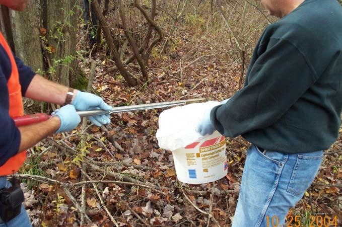

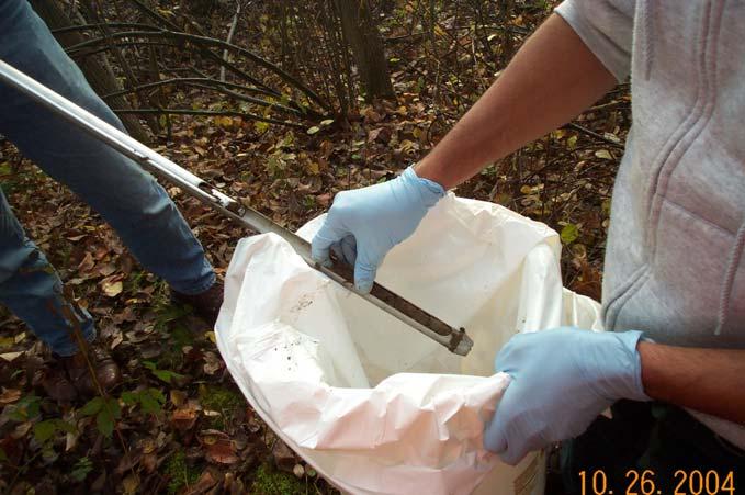
16
17 Sample Processing Eight sample processing steps 1. Log samples into Building1036 (Processing Center) 2. Spread and dry soil or mix sediment 3. Physically process sample a. Prepare soil for sieving (crush; remove rocks/organics) b. Sieve sample (#4 and #10) c. Grind sieved soil 4. Incrementally fill sampling jars 5. Log filled, labeled sampling jars into refrigerator 6. Clean, decon processing station 7. Prepare processing station for next sample 8. Pack and ship samples to labs
18 Storage & Dirty PPE Disposal Equipment Decontamination Station Equipment Calibration & Storage Sample Processing & Preparation Area Empty Cooler Storage Additional Sample Bottle Storage Unprocessed Sample Delivery Final Cooler Holding Area Sample Login, Inprocessing Sample Drying Room Sample Layout, Drying Prep, & Processing Prep Refrigerated Sample Storage Break/Lunch/ Meeting Area Admin Area Sample Packing, Shipping Preparation & Final Check Sample Bottle Storage Supplemental Drying Oven Sampling Equipment Storage = MI sample process prior to processing MKM Engineers, Inc N = MI sample process after to processing = Sample team foot traffic (only) Not to scale DRN BY: ERE DATE: 09/16/04 REV BY: ERE DATE: 09/16/04 PROJ #: REVISION: 1 Figure 1-1 B/1036 Sample Processing Layout RVAAP 14 AOC Characterization Ravenna AAP, OH


19


20


21
22 Statistical Comparison QA/QC Samples RVAAP RESULTS for LEAD Discrete Duplicates MI Duplicates MI QA Samples Matrix Discrete Shallow Soil MI Shallow Soil MI Shallow Soil Sample Population Description Traditional field duplicate QC of MI sample processing QC of MI sample collection Average Relative % Difference (RPD) 24.98% 9.5% 10.7% Average Standard Deviation (precision) Discrete sample data was from separate project.
23 Summary Project initiated in July 2004 Work Plans Completed and approved in September 2004 Significant planning and coordination with the Ohio EPA First large scale implementation of MI Sampling Very successful Laboratory data received, validated and summarized for agency review Preliminary Draft Report submitted in the summer of 2005 Currently responding to comments from review of the Preliminary Draft Report Next Step Risk Assessment as part of the next contract
24 Questions?