Design Details for Constructed Wetlands
|
|
|
- Eustacia Little
- 5 years ago
- Views:
Transcription


1 Design Details for Constructed Wetlands based on the example of the presented by Gerhard Knoll Posch&Partners Consulting Engineers for the Ecological Sanitation Online Course
2 Background: Financing Agency: ADA (Austrian Development Agency) Beneficiary: TBC Hospital Jasenovo, Municipality of Caska, Republic of Macedonia Engineer: Posch&Partners Consulting Engineers (Project Management, Design, Tendering and Construction Supervision) Contractor: DGT ZIKOL, Construction Company, Strumica, Republic of Macedonia Follow-up project after improvement measures on water supply system were realised ( ) Project period: February October 2006


3 Existing Waste Water (WW) Situation Collection of Hospital WW by an old brick sewer in a not maintained and non-operating septic tank Uncontrolled discharge of tank effluents Uncontrolled discharge of laundry effluents
4 Why opting for a Constructed Wetland? Jasenovo Hospital is situated in remote area (on-site treatment necessary) with sufficient land availability Territory was found to be suitable for gravity driven operation (sufficient height difference) no power supply necessary Waste water treatment in proximity to Hospital: CW offer nice appearance in recreational surrounding CW are low on O&M measures operation by trained hospital staff possible
5 Design Parameters Design based on Austrian standard ÖNORM B2505 (standard for use, design, construction and operation of CW) Key points: - Standard valid for CW for communal sewage < 500 PE - Standard covers horizontal sub-surface flow (HSSF) and vertical sub-surface flow (VSSF) CW - Avoidance of toxic substances and stormwater separate sewer system preferred - Nominal hydraulic load: 150 l/(pe*d) - Nominal pollutant load: 60 g BOD 5 /(PE*d) - Mechanical pre-treatment by screen and sedimentation tanks essential avoidance of clogging of CW filter bed
6 Pollution Load Calculation POLLUTION LOAD JASENOVO HOSPITAL Consumer Groups Unit Max. future Units Specific Pollution Load [g BOD5/d] Total future Pollution Load [g BOD5/d] Stationary Patients Bed Ambulant Patients Patient Workers and Management (from 07:00am to 14:00pm) Capita Medical Personnel (permanent) Capita Kitchen meals Laundry kg Domestic consumption (5 houses) Capita (In future houses will be used for private patients) Sub Total g BOD5/d Design population equivalents (PE) (=total BOD5 load / 60g BOD5/PE) 249
7 Main Plant Components Pre-treatment: - Screen with free spacing = 20 mm (manually cleaned) - 3-chamber septic tank V1 : V2 : V3 = 2 : 1 : 1 V tot = 0.25 [m 3 /PE] * 50 [PE] [m 3 /PE] * (249 50) [PE] = 42 m 3 i.e m 3 for first 50 PE and 0.15 m 3 for every PE above 50 Constructed Wetland: Reduction of BOD 5 /(PE*d) to 40 after mech. pre-treatment allowed - Type: VSSF CW 4 m 2 /PE - Area required = 249 [PE] * (40/60) [g BOD 5 /d] * 4 [m 2 /PE] = 665 m 2 = 2 beds with 333 m 2 Max. recommended single bed size 400 m 2
8 Plant Overview OVERFLOW DiPipes 1 DISCHARGE MANHOLE 1/1 MECHANICAL TREATMENT 1/2 CW 1 2/1 DiPipes 2 CW 2 2/2 EWER INFLOW LOADING PIPE DISTRIBUTION SYSTEM LOADING MANHOLES
9 Details Pre-Treatment Screening and 3-Chamber Tank Concrete C25/30 Vertical Section DETAIL T- PIECE: INFLOW TO FLOW DISTRIBUTION SYSTEM
10 Details Pre-Treatment Screening and 3-Chamber Tank Concrete C25/30 Ground View NOTE: Crosswise position of T-pieces Parallel chambers for cleaning gates for closing


11 Construction of Pre-Treatment Unit Concreting base slab 3-chamber tank Reinforcement & shuttering 3-chamber tank


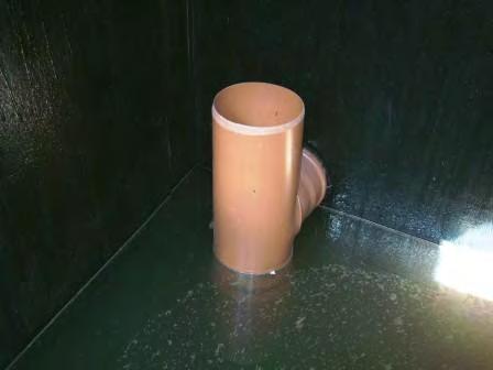
12 Realised Details of Pre-Treatment Unit T-structure in 3-chamber tank Inflow and steel rake Inflow gate
13 Flow distribution & Hydraulic Valves Loading of CW beds with WW shall be intermittently in order to facilitate oxygen diffusion Loading interval between 3 and 6 hours; max. duration / loading: 15 min. Loading by pumps or by hydraulic systems (gravimetrically driven) Hydraulic systems require 1,50m height difference to the CW beds as a minimum Hydraulic systems may require further division of CW beds flow distribution necessary Chosen for Jasenovo: - Use of hydraulic valves - Two separate distrib.systems per CW bed 4 separate systems in total - Flow distribution by another hydraulic valve and pipe system
14 Details Flow Distribution System Vertical Section DISTRIBUTION MANHOLES PREFABRICATED CONCRETE WITH HYDRAULIC VALVE 250 l/min AND FLOW DISTRIBUTION UNIT LOADING MANHOLES CONCRETE C25 / 30 WITH HYDRAULIC VALVES 500 l/min INFLOW FROM 3-CHAMBER TANK TO CW BEDS
15 Details Flow Distribution System Ground View TO CW BEDS INFLOW FROM 3-CHAMBER TANK HV HYDRAULIC VALVE TO CW BEDS


16 Flow Distribution in Practice Distribution Manholes Pipe Inlet Detail for HV 250 for flow distrib. syst. Flow distribution system


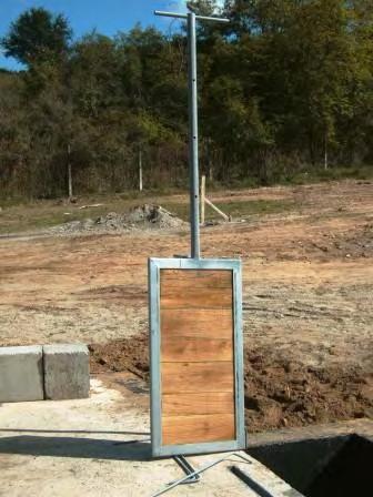
17 Construction of Loading Manholes Loading manholes with tared coating Hydraulic valve 500 l/min Up: floating on inflow water to pre-set max. level Down: weight of flown in water Loading manholes with tarred paper Installation of 4 HV 500 Flexible, chemically resistant sleeve
18 CW Beds (VSSF Beds) Main filter layer shall have a permeability coefficient of k = m/s and be of high mechanical stability (sand, gravel) Avoid unnecessary compaction of layers, also during construction no vehicles on gravel or sand! Beds need to have impermeable base and side walls: - either clay layer (k 10-7 m/s), 30 cm thick, compacted in 2 layers to 95% Proctor density (ρ Pr ) - or adequate sealing foil made of plastic Detail Cross Section CW Beds


 clay in")

19 Excavation and Sealing of CW Beds Excavated CW beds Compaction of sealing clay layer (2 x 15 cm) Compaction of clay in corners Control of compaction by Proctor test
 60cm Transm.")

20 Layers and Drainage of CW Beds Cover layer (gravel 8/16) 10cm Main layer (sand/gr 1/4) 60cm Transm. layer (gravel 4/8) 10cm Clay sealing layer and perforated drainage pipes (solid, non-perforated pipes put over them at embankments, see also slide 24)
21 WW distribution on CW beds WW needs to be equally distributed on CW beds minimum one discharge point per 2m 2 of bed surface Pressure pipes with singular discharge points or perforated (with boreholes) distribution pipes (either laid on bed surface or elevated on suitable blocks) Minimum pipe diameter DN 40, boreholes 8mm Pipes shall be UV resistant and have a small specific coefficient of linear expansion [mm/(m x C)] Stainless steel bolts can be used for fixing spigot socket joints of distribution pipes Distribution pipes shall foresee flushing access and drain-off automatically (avoid freezing) Distance between two parallel pipes shall be limited to 1m High temperature stabilized Polypropylene-Copolymer (HT-PPCO) pipes DN 50, elevated on concrete blocks, were chosen


22 WW Distribution on CW Beds in Practice Drilling boreholes 8mm in distribution pipes Main feeding pipe to CW beds Pipe clamps on concrete blocks Bolts for spigot socket joints Alternatively longitudinally cut PE-pipes can be used


23 WW Distribution on CW Beds in Practice Alignment of concrete blocks Taper piece for flushing Water outflow of distribution pipe Laid distribution system In case of higher flow rates a baffle shall be used
24 Further Plant Components and Details Drainage: - CW base shall be sloped (0.5 1 %) - For better drainage, drainage pipes DN 80 can be laid in max. distance of 3m; for aeration and flushing pipes shall be extended above bed surface (see slide 20) Wetland Plants: - Plants shall have deep roots and reeds have shown best suitability - Planting is best during growing season (spring to summer) but possible year-round - Locally available seedlings (not grown up plants) shall be used - Approximately 5 plants / m 2 shall be planted - In Jasenovo 75% Phragmites Australis and 25% Typhia Latifolia were planted (however in autumn!) Surface run-off: - Avoid inflow of surface run-off of surrounding area (e.g by ditches, etc.); sediments (especially recently after construction) might contribute to clogging of the CW beds Discharge Manhole: Percolated, treated WW shall be collected in a discharge manhole for: - Sampling and water quality control - Weed control in CW beds by raising water levels in CW beds


 Planting in")

25 Planting of Wetland Plants Seedlings of Typhia Latifolia Planting in main layer (not in cover layer) Planting in autumn Phragmites Australies and Typhia Latifolia


26 Discharge System Discharge manhole Water level regulation in CW beds by turning bends in discharge manhole up and down NOTE: Lower water level only very slowly (some cm / d) in order to avoid compaction of filter layers Discharge pipe into outfall drain


27 Final Overview and Costs CW beds Mechanical pre-treatment Total costs*: Supply of Materials: 15,200 Euro Construction Works: 76,700 Euro (average salary of skilled worker in MK: approx. 300 Euro / months) * incl 190m new sewer line


28 Problems encountered in June 2007 Overview plant growth Plant density partially not satisfying re-planting 3-chamber tank not emptied Unsecured joints loosened

29 Thank you! For further inquiries contact: Mr. Gerhard Knoll Posch&Partners Consulting Engineers