Upstream & Downstream
|
|
|
- Rodger Bruce
- 5 years ago
- Views:
Transcription

1 서유택 해양플랜트공학입문

 Trading")

2 Source : Dutch-SHELL Website (SHELL s Business Scope) Upstream & Downstream Exploring for oil / gas Mining oil sand Extracting bitumen Developing field Producing oil / gas CPF (Central Processing Facilities) Trading Refinery Petrochemicals LNG GTL Trading Wind Energy Bio-fuels Re-gasifying LNG Upstream Scope Downstream Scope
?")

3 CPF (Central Processing Facilities)? Gas / Condensate Production for Dawin LNG Project (AU)
 consumption Analysis on max.")
 Export Pipeline")
4 Design process Subsea production system Topside process design Well fluid characteristics Flow-stability free of erosion & corrosion Flow assurance study (multiphase flow) Chemical inhibitor (HI, CI) consumption Analysis on max. liquid surge volume in slug catcher Slug catcher & G/L separator design Gas sweetening unit design Mercury removal unit design Gas dehydration unit design Gas compression unit design Oil/condensate stabilization unit design Oil / condensate storage tank design 8 Produced water treating unit design 9 Utility design (Hot oil / Fuel gas) Export Pipeline Design Flow stability (ex. Two phase formation?) Flow assurance study Surge analysis Sale Gas & Sales Oil (enough for sales spec.)
5 Form Reservoir To Products Reservoir Wellbore HC Products Crude Oil Stabilized Oil Oil Fluid (Black / Volatile Oil) Associated Gas Produced Water Sales Gas Re-injection Gas Water Disposal Re-injection Water Gas Fluid (Dry / Wet / Retrograde Gas) Gas Condensate Sales Gas LPG (C3 & C4) Stabilized Condensate Produced Water Water Disposal


6 Typical CPF : Oil Field Re-injection for IOR / EOR or gas lifting For Dew Point Control Gas Sweetening Gas Dehydration Gas Refrigeration Gas Exporting Sales gas Oil Wellfluid Slug Catcher Compression to HP Compression to MP MP Separator LP Separator De-salter System Oil Stabilizer Stabilized oil to tank Gas Stream Liquid HC stream Well Fluid Stream
7 Typical CPF : Gas Field (1) For Dew Point Control Gas Sweetening Gas Dehydration Gas Refrigeration Gas Exporting Sales gas Gas Wellfluid Slug Catcher Compression to HP Inlet Separator Condensate Stabilizer Stabilized condensate to tank Gas Stream Liquid HC stream Well Fluid Stream
8 Typical CPF : Gas Field (2) For NGL Recovery Gas Sweetening Gas Dehydration Gas Refrigeration Gas Exporting Sales gas Gas Wellfluid Slug Catcher Compression to HP NGL Recovery LPG Inlet Separator Condensate Stabilizer Stabilized condensate to tank Gas Stream Liquid HC stream Well Fluid Stream
9 Design Process Client Requirements & Onshore or Offshore? Main Product (sales gas / stabilized oil / LPG) & EOR (or IOR) & CCS? 1) EOR : Enhanced Oil Recovery 2) IOR : Improved Oil Recovery Well Test Data Analysis (Fluid / Flowing P & T) Block Flow Diagram Completion Process and Equipment Design / PFD & PID CPF Design Completion
10 Project comparison Project Reservoir Fluid Product IOR 1) / EOR 2) CCS 3) SARB-4 (UAE_Abu dhabi) Oil Stabilized Oil Reinjection Gas Y (Gas/Water Injection) N TouatGaz (Algeria) Gas Sales Gas Stabilized Condensate N Y MIDYAN (Saudi) Gas Sales Gas N N AKKAS (Iraq) Gas Sales Gas Stabilized Condensate N N RHIP (Omen) Gas Sales Gas Stabilized Condensate LPG Y (SG Injection) Y 4) Note 1> IOR means Improved Oil Recovery as technology for 2 nd and 3 rd recovery 2> EOR means Enhanced Oil Recovery as technology for 3 rd recovery 3> CCS means Carbon Capture & Storage 4> RHIP process includes CO 2 EOR facilities for another oil field. CO 2 EOR plays a role of CO 2 storage role as well as enhanced production.
 2. Process Design on Artificial Islands 3.")
 2. Reinjection gas and fuel gas 3.")
11 Ex. SARB-4 (Client : ADMO-OPCO / Abu Dahbi) CPF (Central Processing Facilities) Work-scope 1. Process Design on CPF (Zirku Island) 2. Process Design on Artificial Islands 3. Hydraulics on subsea pipeline 4. Flow assurance on subsea pipelines Product (CPF) Artificial Island 1. Stabilized oil (200,000 stb/d) 2. Reinjection gas and fuel gas 3. Reinjection water (sea water) Artificial Island Artificial Islands play a role of WHP.
12 Gas Sweetening Fuel gas 172 barg 414 barg For IOR 1 st Gas Compression 70 barg Gas Dehydration 2 nd Gas Compression 3 rd Gas Compression Reinjection 30 barg Oil Wellfluid Slug Catcher Compression to HP Compression to MP Condensate Processing Gas (< LP) barg Vapor Recovery 7 barg 8.3 barg 0.7 barg MP Separator LP Separator De-salter System 1 barg Oil Stabilizer Stabilized oil to tank Injection Water Produced Water Treating Sea Water Treating for IOR

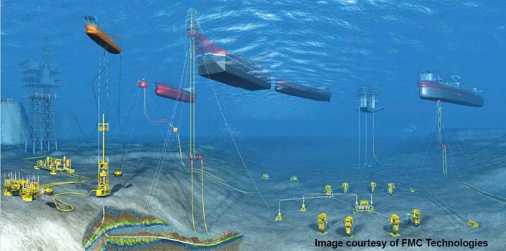
13 Oil FPSO Processes hydrocarbons from subsea template into oil, LPG, sales gas, etc. A converted tanker or purpose built vessel may be ship shaped Eliminate the need for costly long-distance pipelines, which is effective in remote or deep water developments

14 Oil FPSO topside facilities


15 FPSO in West Africa Girassol (TotalFinaElf) : Located of NNW Luanda, Angola m of water : Producing 32 o API crude oil from 23 wells : Total storage capacity 2 million bbl of crude oil : Liquid processing 180,000 bpd : 3 million m 3 /d gas lift with 8 million m 3 /d gas compression and dehydration


 & Gas (80")
16 FPSO in Western Australia Vincent oil field : Located offshore Exmouth in Western Australia : Water depth 350m, 17 o API crude from 8 wells : Oil column thickness 8.5 ~ 19.0 m : Total Liquid processing capacity 120,000 b/d with total storage capacity of 1.2 million barrels of oil : Water (150,000 b/d) & Gas (80 MMscf/d) Injection : Dual sided hull and disconnectable mooring

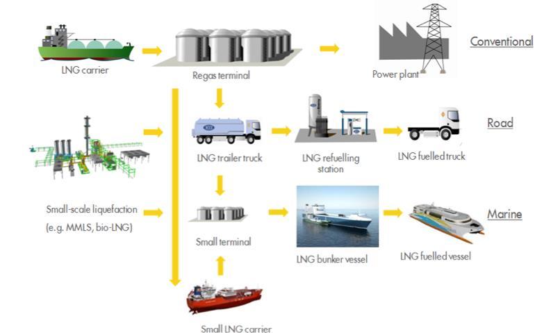
17 LNG value chain
18 Why natural gas? - Sufficient reserves: onshore and offshore - New solutions to non-conventional gas development (FPSO, Shale gas production) Supply Natural gas will be the bridging energy to the next generation at least for several decades Demand - Greener: Less CO2 - Less polluting: Negligible NOx, No SOx, No PM - More economical: Cheaper than crude-driven fuels


19 Why LNG? LNG utilization like crude Short-lead time for LNG infrastructure LNG-fuelled ship propulsion
20 FLNG opening more gas to development Accesses gas unsuitable for baseload development Eliminates pipeline & loading infrastructure costs Reduces security and political risks Constructed in controlled shipyard environment Can relocate facility upon field depletion 4 ~70 fields ~350 fields ~350 fields ~700 fields Tcf 5-50 Tcf 1-5 Tcf Large-Scale LNG Tcf Mid-Scale and Tcf Floating LNG Tcf ~ 1,000 fields < 0.1 Tcf ~ 4,000 fields

 (e.g., Dual MR, Mixed Fluid Cascade) SBM Offshore 2.")
21 Two distinct development paths emerging Characteristic Small-scale Floating LNG Large-scale Floating LNG Liquefaction capacity: less than 3.0 mtpa 3.5 to 6.0 mtpa Required reserves: 0.5 to 3.0 Tcf more than 3.0 Tcf Hull: Ship-like Barge-like Storage capacity: up to 220,000 m 3 more than 250,000 m 3 Liquefaction processes: Simpler processes Baseload-type processes (e.g., Single Mixed Refrigerant processes, dual expander processes) (e.g., Dual MR, Mixed Fluid Cascade) SBM Offshore 2.5 mtpa Shell 5-6 mtpa concept

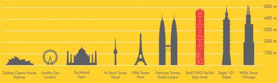
22 Prelude FLNG

23 Prelude FLNG in operation

24 FLNG process overview

25 Field specific and pre-treatment systems

26 Field specific and pre-treatment systems Field specific and pre-treatment systems are conventional and not new to the offshore environment. Energy optimization is required to integrate the heat- and energy demanding systems in the overall topside. Optimize and include the pre-treatment and field specific systems in the fuel gas balance. Tall columns with internals must be carefully designed in order to minimize flow maldistribution. Avoiding stabilization issues of the condensate or recycle of middle components like propane and butane through the process system.
 Source: Mustang")
27 Liquefaction choices far from mature Black & Veatch PRICO SMR Process Need simple, robust and compact liquefaction solutions Single mixed refrigerant cycles Gas expander-based cycles Concerns Process efficiencies Scale-up performance LPG refrigerant storage Marine performance and reliability Source: Black & Veatch Mustang NDX-1 Process (patent pending) Source: Mustang Engineering
28 LNG Properties LNG 는천연가스를저장과수송이용이하도록액체로전환시킨것 LNG 와천연가스부피비는 1/600 (- 162 o C, 상압조건에서액화 ) LNG 의매우낮은온도로인해 cryogenic liquid 로취급되며, 취급을위해특수한기술과설비가요구됨. Cryogenic 상태의 LNG 에접촉되는모든물질은빠르게냉동되면서강도와기능을잃어버리기때문에, LNG 보관을위해서는 container 매체선정에주의를기울여야함. LNG 는무색, 무취하며, 부식성이없고, 불연성이고, 무독성. LNG 물성은다음의사항들로구분된다. 조성 끓는점 밀도및 specific gravity 가연성 발화온도

29 LNG composition 천연가스의조성은가스전의특성과처리공정의종류에따라달라짐. 일반적으로 LNG 생산에사용되는천연가스는메탄과에탄, 프로판, 부탄그리고소량의 heavy 탄화수소로이루어지는혼합가스. 불순물로는질소와이산화탄소, 황화수소및물등이포함될수있지만, 액화공정전에모두제거됨. 메탄이주요성분으로보통 85 vol% 이상.
. 저온의 LNG 가따뜻한공기또는물에노출되는경우, 주변온도가 LNG 의끓는점보다높기때문에 LNG 표면에서기화가시작됨.")
30 LNG boiling point, density & specific gravity LNG 의끓는점은조성에따라변할수있지만, 일반적으로 -162 o C (-259 o F). 저온의 LNG 가따뜻한공기또는물에노출되는경우, 주변온도가 LNG 의끓는점보다높기때문에 LNG 표면에서기화가시작됨.


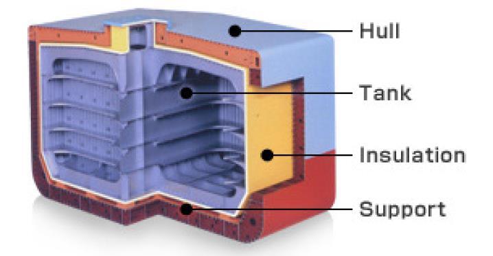
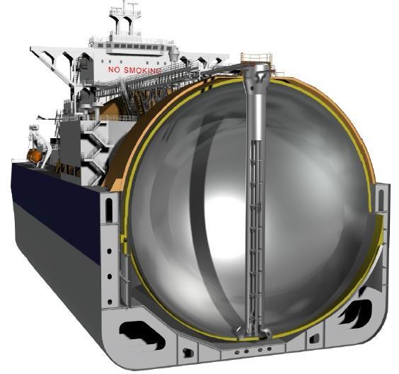
31 LNG Carrier Which type of tanks in it?

32 Cargo handling and fuel gas system
33 BOG liquefaction technology Collection drum Coldbox BOG Refrigeration cycle LNG to Cargo Tanks Effective to treat continuous BOG To treat the BOG during LNG bunkering Considerable capacity: 40 ton/hr to treat 40 ton BOG for 1 hr Intermittent operation: 1 hr operation + 9 hr stop


34 LNG-fuelled ship propulsion Regulation on ship CO2 emission Regulation on fuel quality in ECA Fuel economics

35 Regulation on fuel quality within emission control area (ECA) Currently, the seas around Europe and the North America are ECAs. ECAs are expanding, ultimately all over the world.
 from 2020 or 2025 globally MARPOL Annex VI")
36 Regulation on fuel quality within emission control area (ECA) Regulations on emissions from ships, especially for SOx Stringent regulation on fuel quality Effective from 2015 for ECAs (emission control areas) from 2020 or 2025 globally MARPOL Annex VI Requirements - SOx
 5%- 7%-Hydro")


37 Impact of LNG fuelled propulsion World Energy Mix (BP Energy statistics 2011) 5%- 7%-Hydro Nuclear 1%- Renewable 33%- Oil 23%-Coal 24%-Gas LNG = 9% of Gas or 2% of total Shipping is consuming 3% of total world energy million tonnes, 250 billion US$/yr LNG-fuelled shipping will consume 1.5 times the current world LNG trade. The world LNG consumption will increases to 250%.

38 LNG fuelled propulsion growing LNG fuelled propulsion: in service
39 Thank you!