THREE RIVERS LEVEE IMPROVEMENT AUTHORITY 1114 Yuba Street, Suite 218 Marysville, CA Office (530) Fax (530)
|
|
|
- Albert Doyle
- 6 years ago
- Views:
Transcription
 Levee")
1 THREE RIVERS LEVEE IMPROVEMENT AUTHORITY 1114 Yuba Street, Suite 218 Marysville, CA Office (530) Fax (530) November 20, 2013 Mr. Eric Simmons Regional Engineer, FEMA Region IX 1111 Broadway, Suite 1200 Oakland, CA Subject: Reclamation District 784 Levee System Three Rivers Levee Improvement Authority (TRLIA) Levee Certification for FEMA Accreditation Dear Mr. Simmons: TRLIA has been working diligently since 2004 to provide improvements and repairs to the Reclamation District (RD) 784 Levee System. These efforts were not only to assure that the levees could pass the 100-year flood but were accomplished to also provide 200-year flood protection to south Yuba County. In May 2010 TRLIA provided certification information to FEMA for the following levee segments: Yuba River South Levee (UPRR to Simpson Lane) Yuba River South Levee (WPRR to UPRR) Feather River East Levee Segment 3 Feather River East Levee Segment 2 Feather River East Levee Segment 1 Bear River North Setback Levee Upper Bear North Levee (Setback Levee to WPIC) and WPIC West Levee (Including Olivehurst Detention Basin (ODB) Ring Levee) FEMA accredited these levees at that time. The remaining segment of the RD 784 Levee System, Yuba River South Levee (Simpson Lane to Goldfields), was covered under a Provisionally Accredited Levee agreement with FEMA. This agreement has since expired but TRLIA has completed levee repairs on this last segment. The purpose of this letter is to supply FEMA with the proper information, technical evaluations and certifications in accordance with the provisions of 44 Code of Federal Regulations (CFR) for the Yuba River South Levee (Simpson Lane to Goldfields) segment of the RD 784 Levee System to become fully accredited in the National Flood Insurance Program (NFIP).
2 Eric Simmons Page 2 Submit RD 784 Supplemental Certification Information November 20, 2013 Evaluation, design and construction of repairs of the Yuba River South Levee (Simpson Lane to Goldfields) segment has been accomplished by a team of engineering consultants under TRLIA s management. This team consists of HDR Inc. of Folsom, California; Kleinfelder Inc. of Sacramento, California; MHM Engineering of Marysville, California; and MBK Engineers of Sacramento, California. Design and construction of the recent repairs were accomplished using the criteria developed by the US Army Corps of Engineers (USACE) and the California Department of Water Resources (DWR). The attached documentation is a supplement to the Certification Summary Report that was submitted to FEMA in 2010 and provides a brief summary of each technical evaluation performed with respect to levee certification and includes a corresponding Engineer s Opinion, stamped by a licensed Professional Engineer, at the end of the document. These opinions are being submitted by TRLIA to demonstrate that the appropriate standard of care has been followed to certify that the Yuba River South Levee (Simpson Lane to Goldfields) segment of the RD 784 Levee System meets the criteria listed in 44 CFR TRLIA s certification, which is also stamped by a licensed Professional Engineer, is provided in Section 6 of the Certification Summary Supplement. The RD 784 Levee System terminates at the Yuba Goldfields with the assumption that the Goldfields serve as high ground. TRLIA is evaluating this assumption and the status of this evaluation is discussed in Section 5 of the Certification Summary Supplement. These improvements and repairs were accomplished with the assistance of Yuba County, Reclamation District 784, the Yuba County Water Agency, local land owners, the State of California Central Valley Flood Protection Board, the State of California Department of Water Resources, the State of California Department of Fish and Game, U.S. Army Corps of Engineers, and the U.S. Fish and Wildlife Service. Please feel free to contact me any time at (530) , or Ric Reinhardt of MBK Engineers at (916) , so we may answer questions or provide any other needed information on the Supplemental Certification Information. Sincerely, Paul G. Brunner, P.E. Executive Director Three Rivers Levee Improvement Authority 2 Attachments: 1. Certification Summary Supplement Report 2. Supporting Reports (2 Boxes)
3 Eric Simmons Page 3 Submit RD 784 Supplemental Certification Information November 20, 2013 Cc: w/o Attachments Jay Punia Central Valley Flood Protection Board Kelly Fucciolo DWR Liz Bryson - DWR Megan Nagy Corps of Engineers Ric Reinhardt MBK Engineers Daniel Jabbour HDR Consultants Robert Bendorf Yuba County Kevin Mallen Yuba County Curt Aikens YCWA Steve Fordice Reclamation District 784 TRLIA Board Members Donna Stottlemeyer TRLIA Board Secretary
4 THREE RIVERS LEVEE IMPROVEMENT AUTHORITY 1114 Yuba Street, Suite 218 Marysville, CA Office (530) Fax (530) Certification Summary Supplement FEMA Accreditation Project Yuba South Levee (Simpson Lane to the Goldfields) Yuba County, California November 2013
5
6 Yuba South Levee (Simpson Lane to the Goldfields) Certification Summary Supplement Table of Contents Certification Summary Supplement FEMA Accreditation Project Yuba South Levee (Simpson Lane to the Goldfields) 1 General [44 CFR 65.10(a)] Purpose of Certification Reclamation District 784 Levee System Description Design Criteria [44 CFR 65.10(b)] Freeboard [44 CFR 65.10(b)(1)] Closures [44 CFR 65.10(b)(2)] Embankment Protection [44 CFR 65.10(b)(3)] Embankment and Foundation Stability [44 CFR 65.10(b)(4)] Settlement [44 CFR 65.10(b)(5)] Interior Drainage [44 CFR 65.10(b)(6)] Operations Plans and Criteria [44 CFR 65.10(c)] Closures [44 CFR 65.10(c)(1)] Interior Drainage Systems [44 CFR 65.10(c)(2)] Other Operation Plans and Criteria [44 CFR 65.10(c)(3)] Maintenance Plans and Criteria [44 CFR 65.10(d)] Yuba Goldfields Certification Requirements [44 CFR 65.10(e) & 65.2] Certification Statement for FEMA Accreditation Definitions and Conditions Definitions Certification Conditions Quality Control November 2013 i
7 Yuba South Levee (Simpson Lane to the Goldfields) Certification Summary Supplement List of Supporting Documents Certification Summary Supplement FEMA Accreditation Project RD 784 Levee System (Yuba South Levee, Simpson Lane to the Goldfields) Plate Plate 1 Figure Figure 1 TRLIA Repair Program RD 784 Levee System Appendices- Include Engineer s Opinion Statements in Appendix or Sub-appendix as appropriate A B C D E F G Freeboard (Engineer s Opinion and Supporting Report) Embankment Protection (Engineer s Opinion, Supporting Report Separately Bound) Embankment and Foundation Stability (Engineer s Opinion, Supporting Report Separately Bound) Settlement (Engineer s Opinion, Supporting Report Separately Bound) Interior Drainage Study (Engineer s Opinion, Supporting Report Separately Bound) Operation & Maintenance Manual for RD 784 (Engineer s Opinion, Supporting Report Separately Bound) BOSC Credentials and BOSC Quality Control Report Supporting Reports MBK Engineers, Three Rivers Levee Improvement Authority Phase 4 Erosion Investigation, dated February Kleinfelder, Problem Identification Report, dated September 29, Upper Yuba Levee Improvement Project, Yuba River South Levee Evaluation, Simpson Lane to Yuba Gold Fields, Reclamation District No. 784, Yuba County, California This report contains the results of geotechnical investigations and provided preliminary repair recommendations. MWH, Groundwater Impacts Evaluation Report, dated December Evaluation of Groundwater Impacts from the Upper Yuba River South Levee Repair Activities. This report evaluates the potential for regional and local groundwater impacts from constructing a slurry cutoff wall for the UYLIP. HDR, Draft Initial Study/Mitigated Negative Declaration, Upper Yuba Levee Improvement Project (Simpson Lane to the Goldfields), Yuba County, California, dated February CEQA document issued for public review. November 2013 ii
8 Yuba South Levee (Simpson Lane to the Goldfields) Certification Summary Supplement HDR, Final Initial Study/Mitigated Negative Declaration, Upper Yuba Levee Improvement Project (Simpson Lane to the Goldfields), Yuba County, California, dated April CEQA document adopted by the TRLIA Board. MBK, Hydraulic and Hydrologic Analysis Yuba River Patrol Road Levee, dated March This report provides the final design water surface elevations. Kleinfelder, Geotechnical Borrow Site Evaluation, dated June 7, 2010, Geotechnical Borrow site Evaluation TRLIA Borrow Area 1, Upper Yuba Levee Improvement Project, Yuba river south Levee Evaluation, Yuba County, California. This report provides an evaluation of quality and quantity of borrow material in the adjacent borrow site. Kleinfelder, Revised Geotechnical Basis of Design, dated June 11, Upper Yuba Levee Improvement Project, Yuba River South Levee Evaluation, Reclamation District 784, Yuba County, California. This report contains additional analysis on the final repair recommendations. HDR, Upper Yuba Levee Improvement Project, 100% Design Submittal Design Documentation Report, Upper Yuba Levee Improvement Project, Yuba River Basin, California (Sta to Sta ), dated June 21, This report identifies the standards used in the design of the UYLIP, describes the design assumptions and design criteria, summarizes the methods and results of the hydraulic and geotechnical analyses of the UYLIP, and describes the key features of the proposed facility. MHM, Interior Drainage Study PAL Area Extension, LOMR Application Narrative East Linda Extension, FEMA Accreditation Project, Three Rivers Levee Improvement Authority, August 10, 2010 (Revised September 17, 2010). U.S. Army Corps of Engineers, Sacramento District, Final Environmental Assessment, Upper Yuba Levee Improvement Project (Simpson Lane to the Goldfields, Yuba County California, dated September NEPA Document to support Section 408 and Section 104 Credit Requests. HDR, Upper Yuba Levee Improvement Project, Drawings and Specifications Conformed for Construction, May 23, 2011 Drawings and specifications governing construction of the UYLIP levee repairs. MBK, Bear River North Levee, WPIC West Levee, and Yuba River South Levee, Addendum to: Supplement to Standard Operation and Maintenance Manual Sacramento River Flood Control Project, Unit No. 145 Part No. 1, January 2008 (Revised March 2010, Revised June 2013). HDR, Construction Documentation Report, Upper Yuba Levee Improvement Project, Three Rivers Levee Improvement Authority, March November 2013 iii
9 Yuba South Levee (Simpson Lane to the Goldfields) Certification Summary Supplement November 2013 iv
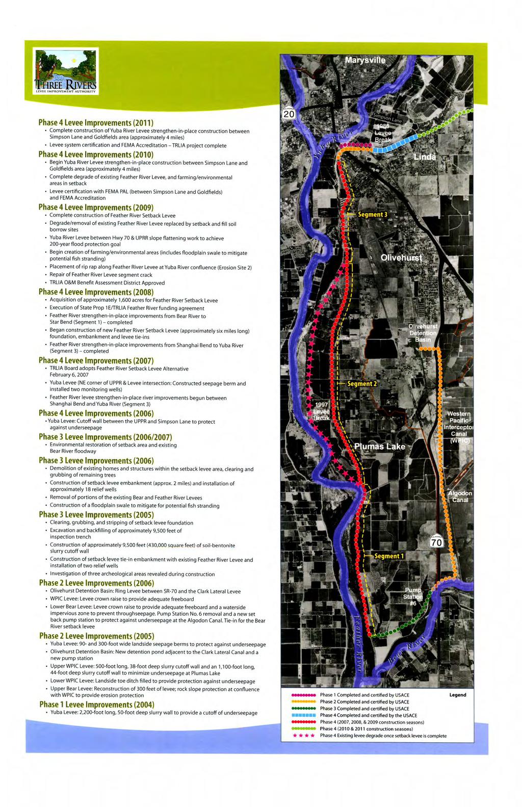
10 Yuba South Levee (Simpson Lane to the Goldfields) Certification Summary Supplement 1 General [44 CFR 65.10(a)] 1.1 Purpose of Certification The Three Rivers Levee Improvement Authority (TRLIA) has completed repairs to the levees surrounding Reclamation District (RD) 784 in south Yuba County. These repairs have been underway since 2004 with the purpose to provide both Federal Emergency Management Agency (FEMA) 100- year certification and 200-year flood protection to South Yuba County. The purpose of this document is to supply FEMA with additional information, technical evaluations, and certifications in accordance with the provisions of 44 Code of Federal Regulations (CFR) for the RD 784 Levee System to become fully accredited in the National Flood Insurance Program (NFIP). This document covers only a portion of the RD 784 Levee System (Yuba South Levee [Simpson Lane to the Goldfields]) and is a supplement to the Certification Summary Report submitted to FEMA on May 5, Evaluation, design, and construction of repairs of the RD 784 Levee System were accomplished by a team of engineering consultants under TRLIA s management. This team consisted of GEI Consultants, Inc. of Sacramento, California; HDR Inc. of Folsom, California; Kleinfelder Inc. of Sacramento, California; MHM Engineering of Marysville, California; and MBK Engineers of Sacramento, California. Design and construction of the recent repairs were accomplished using the criteria developed by the U.S. Army Corps of Engineers (USACE) and the California Department of Water Resources (DWR). This document briefly summarizes each technical evaluation performed with respect to levee certification and includes a corresponding Engineer s Opinion, stamped by a licensed Professional Engineer, at the end of the document. These opinions are being submitted by TRLIA to demonstrate that the appropriate standard of care has been followed to certify that the RD 784 Levee System meets the criteria listed in 44 CFR TRLIA s certification, which is also stamped by a licensed Professional Engineer, is provided in Section 5 of this Certification Summary Supplement. 1.2 Reclamation District 784 Levee System Description To mitigate the risk of flooding and prevent the level of damage experienced during past floods, the RD 784 Levee System was constructed by the USACE and local interests beginning in the early 1900s and continues to be improved (see Figure 1). The completed system consists of the following key features: 29.9 miles of earthen embankment Two closure structures Five pumping stations (PS) at the line of protection (PS 9, PS 3, PS 2, PS 6, and Olivehurst Detention Basin [ODB]) Three gravity drains at the line of protection (PS 2, PS 6, and ODB) Five interior pumping stations (PS 1, PS 4, PS 5, PS 7, and PS 8) Appurtenant drainage facilities (62 Miles of Drainage Channels and 9 Detention Basins) A system of earthen levees was designed and constructed to manage flooding from the Yuba River, the Feather River, the Bear River, and the Western Pacific Interceptor Canal (WPIC). November 2013 Page 1
11 Yuba South Levee (Simpson Lane to the Goldfields) Certification Summary Supplement Five pumping stations were built to remove local runoff when high river levels prevent natural drainage to the rivers. Five additional interior pumping stations lift stored water from detention basins into a system of channels which convey interior drainage to the pump stations at the levees. Starting in 2004 TRLIA initiated designs and projects to increase the reliability of the RD 784 Levee System. TRLIA has completed the alterations described below (see Plate 1): Phase 1 Construct a 50-foot-deep slurry cutoff wall in the south levee of the Yuba River between Highway 70 and the 1986 levee breach. Phase 1 was completed in November Phase 2 Raise and strengthen portions of the north levee of the Bear River and the west WPIC levee; construct a seepage berm along the south levee of the Yuba River east of Highway 70 and west of the Union Pacific Railroad (UPRR); construct a new replacement Pump Station No. 6 (PS 6) on the Bear River north levee just west of Highway 70; and construct a detention basin, pump station, and ring levee near Olivehurst. Phase 2 construction was completed in Phase 3 Construct a two mile setback levee along the Bear River north of the original tie-in of the north levee of the Bear River with the east levee of the Feather River. Phase 3 construction was completed in Phase 4 Strengthen the south levee of the Yuba River west of the Western Pacific Railroad crossing (Project Levee Mile [PLM] 0.0 to PLM 0.3); strengthen the south levee of the Yuba River between the UPRR (PLM 0.9) and the Yuba Gold Fields (PLM 6.1); and improve the east levee of the Feather River between the south levee of the Yuba River tie-in (PLM 26.1) and the Phase 3 Bear River levee tie-in (PLM 13.3). The status of the Phase 4 work is as follows: o South levee of the Yuba River strengthening between PLM 0.9 and PLM 2.2 was completed in o Designs for strengthening of the south levee of the Yuba River from PLM 0.0 to 0.3, east levee of the Feather River from the south levee of the Yuba River tie-in to about one mile north of Murphy Road (PLM 26.1 to PLM 23.4), (Feather Segment 3) and east levee of the Feather River south of Star Bend (PLM 17.2 to PLM 13.3) (Feather Segment 1) were completed in May Construction of these levee strengthening measures was completed in Completion of erosion protection at the Erosion Site 2 in Feather Segment 3 was completed in o Designs for a setback levee to replace the east levee of the Feather River from about one mile north of Murphy Road (PLM 23.4) to Star Bend (PLM 17.2) (Feather Segment 2) were initiated in April 2007 and completed in February Construction of the setback levee started in the summer of 2008 and was completed in o Designs for strengthening of the south levee of the Yuba River from PLM 2.2 to 6.1 were completed in June Construction of the levee strengthening measures was completed in November 2013 Page 2
12 Yuba South Levee (Simpson Lane to the Goldfields) Certification Summary Supplement Alterations have been completed on the following system segments (see Figure 1): 1. Yuba River South Levee (Simpson Lane to the Goldfields [Unit 7]) 2. Yuba River South Levee (UPRR to Simpson Lane [Unit 1]) 3. Yuba River South Levee (WPRR to UPRR [Unit 1]) 4. Feather River East Levee Segment 3 (Unit 2) 5. Feather River East Levee Segment 2 (Unit 9) 6. Feather River East Levee Segment 1 (Unit 2) 7. Bear River North Setback Levee (Unit 8) 8. Upper Bear North Levee (Setback Levee to WPIC [Unit 3]) and WPIC West Levee (Unit 4) (Including Olivehurst Detention Basin (ODB) Ring Levee) Certification information on Segments 2-8 was provided to FEMA in a Certification Summary Report on May 5, At that time Segment 1 (Unit 7) was a Provisionally Accredited Levee (PAL). The PAL agreement for Segment 1 expired in June 2010, and TRLIA subsequently initiated levee repairs in 2011 and completed them in This Certification Summary Supplement has been prepared to provide similar certification information for the Yuba River South Levee (Simpson Lane to the Goldfields [Unit 7]), Segment 1, as was presented for the rest of the system, Segments 2-8, on May 5, November 2013 Page 3
13 Yuba South Levee (Simpson Lane to the Goldfields) Certification Summary Supplement November 2013 Page 4
14 Yuba South Levee (Simpson Lane to the Goldfields) Certification Summary Supplement 2 Design Criteria [44 CFR 65.10(b)] 2.1 Freeboard [44 CFR 65.10(b)(1)] MBK performed an analysis to determine the amount of freeboard along the Yuba River South Levee (Simpson Lane to the Goldfields) reach of the RD 784 Levee System in accordance with the 44 CFR 65.10(b)(1). This section states the following: 1. Riverine levees must provide a minimum freeboard of three feet above the water surface level of the base flood. An additional one foot above the minimum is required within 100 feet on either side of structures (such as bridges) riverward of the levee or wherever the flow is constricted. An additional one-half foot above the minimum at the upstream end of the levee, tapering to not less than the minimum at the downstream end of the levee, is also required. 2. Occasionally, exceptions to the minimum riverine freeboard requirement described in paragraph (b)(1)(i) of this section, may be approved. Appropriate engineering analyses demonstrating adequate protection with a lesser freeboard must be submitted to support a request for such an exception. The material presented must evaluate the uncertainty in the estimated base flood elevation profile and include, but not necessarily be limited to an assessment of statistical confidence limits of the 100-year discharge; changes in stagedischarge relationships; and the sources, potential and magnitude of debris, sediment and ice accumulation. It must be also shown that the levee will remain structurally stable during the base flood when such additional loading considerations are imposed. Under no circumstances will freeboard of less than two feet be accepted. MBK determined freeboard along the levee by calculating the difference in elevation between the top of the levee and the base flood, at intervals of approximately 100 feet. Based on MBK s computations, this reach of the RD 784 Levee System has riverine freeboard of at least 5 feet or more for the 100-year flood event. This freeboard is greater than the required minimum of 3 feet and sufficiently protects against the base flood. No river crossings are present in this reach. An Engineer s Opinion regarding freeboard signed by a Licensed Professional Engineer is included in Appendix A of this Certification Summary Supplement document. A report that is a supplement to Appendix A (Freeboard) of the May 2010 Certification Summary, FEMA Accreditation Project, RD 784 Levee System, Yuba County, California is also included in Appendix A. This report is entitled Freeboard (Supplement), Yuba River South Levee in the Upper Yuba Levee Improvement Project Yuba County, California, prepared by MBK Engineers (dated May 17, 2013). The Freeboard Report provides information on the Hydrologic and Hydraulic Analyses and provides freeboard values for this reach of the RD 784 Levee System that is the subject of this Certification Summary Supplement Report. 2.2 Closures [44 CFR 65.10(b)(2)] All openings in the levee system have been fitted with closure structures in accordance with 44 CFR 65.10(b)(2). This section states the following: November 2013 Page 5
15 Yuba South Levee (Simpson Lane to the Goldfields) Certification Summary Supplement All openings must be provided with closure devices that are structural parts of the system during operation and design according to sound engineering practice No closure structures are present in the Yuba South Levee from Simpson Lane to the Goldfields. Road crossings occur at Dantoni Road and Griffith Avenue. These crossings are over the top of the levee and do not lower the levee grade. 2.3 Embankment Protection [44 CFR 65.10(b)(3)] HDR assessed the adequacy of existing embankment protection over the length of the Yuba River South Levee from Simpson Lane to the Goldfields. The assessment was conducted in accordance with the 44 CFR 65.10(b)(3). This section states the following: Engineering analyses must be submitted that demonstrate that no appreciable erosion of the levee embankment can be expected during the base flood, as a result of either currents or waves, and that anticipated erosion will not result in failure of the levee embankment or foundation directly or indirectly through reduction of the seepage path and subsequent instability. The factors to be addressed in such analyses include, but are not limited to: Expected flow velocities (especially in constricted areas); expected wind and wave action; ice loading; impact of debris; slope protection techniques; duration of flooding at various stages and velocities; embankment and foundation materials; levee alignment, bends, and transitions; and levee side slopes. There are two types of constructed embankment protection along this reach of the RD 784 Levee System: grassed slopes (hydroseed) and riprap revetment. The waterside slope of the levee received hydroseed from Station to Station (Simpson Lane to the area west of the Goldfields) then riprap revetment from Station to (Goldfields). Riprap revetment was placed along the last portion of this reach to protect against erosion from concentrated flows which can exit from the Goldfields at the end of the levee. During the 1997 flood event, flows did exit from the Goldfields and eroded a portion of the levee. The 1997 Flood was the only time that this has ever happened. Based on HDR s evaluation of this levee reach, the potential for erosion of the levee embankment or foundations from currents, waves, or debris during the base flood is expected to occur infrequently and be localized. This opinion assumes RD 784 will continue regular maintenance of the constructed embankment protection features and that embankment protection for any future levee modifications is designed and constructed in accordance with applicable USACE criteria and guidance. Regular maintenance includes replacement and upkeep of riprap, control of vegetation, and repair of localized erosion and animal burrow damage. The levee erosion potential of the Yuba River South Levee between Simpson Lane and the Goldfields was evaluated based on anticipated design water velocities, embankment side slopes, soil characteristics, channel sinuosity and uniformity, and performance history for the existing levee. November 2013 Page 6
16 Yuba South Levee (Simpson Lane to the Goldfields) Certification Summary Supplement Criteria for maximum permissible water velocities were adopted from USACE guidelines for the design of flood control channels (EM ). Based on the Hydraulic Basis of Design Report (MBK, March 2010), flows occur along the waterside of this levee very infrequently due to training berms in the floodway which normally and have historically restricted flows to the north side of the floodway. The estimated maximum flow velocity along the Yuba River South Levee in this reach was computed to range from 1 to 2 feet per second (fps). The USACE guidelines, referenced above, show maximum permissible mean channel velocities for bare-earth channels ranging from 2 fps for fine sand to 6 fps for clay. The Yuba River South Levee in this reach was recently reconstructed with clayey soils. For grass-lined channels, maximum permissible velocities range from 5 fps to 6 fps depending on type of soil and grass cover. Based on these guidelines, it was judged that the well-established vegetation on the levee slope would provide adequate erosion protection. This judgment was based on the following factors: The calculated water velocities are equal or less than the maximum permissible velocities for vegetated flow channels. The existing levee embankment material is free of significant erosion, and there was not significant erosion of the levee reported after previous flood events. The existing levee slopes are generally well vegetated. The analysis of wind setup and wave runup was included in the June 21, 2010, 100% Design Submittal Design Documentation Report by HDR. The maximum water surface capable of generating wind and wave was evaluated for the 1 in 200-year flood event. Three different sections (Station , Station , and Station ) were analyzed along the reach. The table below provides input and results for this evaluation adjusted for the 100-year water surface elevations. Wave Evaluation Station Fetch Length (mi) Design Wind (mph) Design Wave Height (ft.) Wave Run-up (ft.) Slope Roughness Correction Factor N/A Adjusted Run-up (ft.) Freeboard above 100-year water elevation (ft.) Wind Set-up (ft.) Wave Run-up plus Wind set-up (ft.) Excess Freeboard above (Wind and Wave Set-up (ft.) These magnitude waves would be contained within the design freeboard over the base flood elevation. Detailed analysis of wave-driven erosion has not been completed. However, it was concluded that the potential for erosion would be infrequent and localized and any resulting damage November 2013 Page 7
17 Yuba South Levee (Simpson Lane to the Goldfields) Certification Summary Supplement would be mitigated through proper maintenance and flood fighting techniques. Minimal wind erosion during the 100-year flood event would not jeopardize levee stability. An Engineer s Opinion regarding embankment protection for this RD 784 Levee System Reach signed by a Licensed Professional Engineer is included in Appendix B of this Certification Summary Supplement document. 2.4 Embankment and Foundation Stability [44 CFR 65.10(b)(4)] The Yuba River South Levee from Simpson Lane to the Goldfields consists of approximately 3.9 miles of earthen levee embankment. Kleinfelder evaluated the embankment and foundation stability. The evaluation was conducted by performing the following analyses and assessments for this levee reach: Seepage analyses of selected embankment sections. Global stability analyses of selected embankment sections. Strength and stability analyses of selected embankment sections. Impact assessment of penetrations. The above analyses and assessments were performed in accordance with the 44 CFR 65.10(b)(4), which states the following: Engineering analyses that evaluate levee embankment stability must be submitted. The analyses provided shall evaluate expected seepage during loading conditions associated with the base flood and shall demonstrate that seepage into or through the levee foundation and embankment will not jeopardize embankment or foundation stability. An alternative analysis demonstrating that the levee is designed and constructed for stability against loading conditions for Case IV as defined in the U.S. Army Corps of Engineers (COE) manual, Design and Construction of Levees'' (EM , Chapter 6, Section II), may be used. The factors that shall be addressed in the analyses include: Depth of flooding, duration of loading, embankment geometry and length of seepage path at critical locations, embankment and foundation materials, embankment compaction, penetrations, other design factors affecting seepage (such as drainage layers), and other design factors affecting embankment and foundation stability (such as berms). The following information provides a general discussion on the Kleinfelder evaluation for the Yuba River South Levee from Simpson Lane to the Goldfields reach, and provides an associated report reference for the embankment and foundation stability evaluations. The embankment and foundation stability assessment by Kleinfelder for the Yuba River South Levee from Simpson Lane to the Goldfields reach included seepage and stability evaluations as presented in the June 11, 2010 Revised Geotechnical Basis of Design report, Upper Yuba Levee Improvement Project, Yuba River South Levee Evaluation, Reclamation District 784, Yuba County, California, in 2 Volumes, prepared by Kleinfelder. Levee improvement features, summarized in the table below, were designed and constructed based on the findings of the seepage and stability assessment. Details about the construction activities for the levee improvement project, including slope stability and November 2013 Page 8
18 Yuba South Levee (Simpson Lane to the Goldfields) Certification Summary Supplement seepage mitigation features, are presented in the March 2013 Construction Documentation Report, Upper Yuba Levee Improvement Project, Three Rivers Levee Improvement Authority, prepared by HDR. Levee Improvements for the Yuba River South Levee from Simpson Lane to the Goldfields Design Station Interval Problem Identified Levee Improvement Activity to None No work proposed to Provide 20 foot crown width, 3H:1V waterside (WS) Geometry Corrections slope and 2H:1V landside (LS) slope to Geometry Corrections Provide 20 foot crown width and 2H:1V LS slope (Crown & LS) to Geometry Corrections Provide 20 foot crown width and 3H:1V WS slope (Crown and WS) to None No work proposed Cutoff Wall WS of Existing Wall Through-Seepage and 65-foot-deep, 3-foot-wide soil bentonite cutoff wall to Underseepage through levee embankment; Estimated Toe Elevation of Geometry Corrections Cutoff Wall: +13 feet; Provide 20 foot crown width, 3H:1V WS slope and 2H:1V LS slope to to to to to to Through-Seepage and Underseepage Geometry Corrections Through-Seepage and Underseepage Geometry Corrections Through-Seepage and Underseepage Geometry Corrections Through-Seepage and Underseepage Geometry Corrections Through-Seepage and Underseepage Geometry Corrections Through-Seepage and Underseepage Geometry Corrections 65-foot-deep, 3-foot-wide soil bentonite cutoff wall through levee embankment; Estimated Toe Elevation of Cutoff Wall: +13 feet; Provide 20 foot crown width, 3H:1V WS slope and 2H:1V LS slope 70-foot-deep, 3-foot-wide soil bentonite cutoff wall through levee embankment; Estimated Toe Elevation of Cutoff Wall: 10 feet; Provide 20 foot crown width, 3H:1V WS slope and 2H:1V LS slope 55-foot-deep, 3-foot-wide soil bentonite cutoff wall through levee embankment; Estimated Toe Elevation of Cutoff Wall: +25 feet; Provide 20 foot crown width, 3H:1V WS slope and 2H:1V LS slope 45-foot-deep, 3-foot-wide soil bentonite cutoff wall through levee embankment; Estimated Toe Elevation of Cutoff Wall: +35 feet; Provide 20 foot crown width, 3H:1V WS slope and 2H:1V LS slope Landside Stability/Seepage Berm: Thickness of 5 feet, Width of 80 feet from levee toe; Provide 20 foot crown width, 3H:1V WS slope and 2H:1V LS slope Transition at End of Berm into Goldfields. Thickness varies from 5 feet to height of levee, Width varies from 80 feet to 150 feet from levee toe; Provide 20 foot crown width, 3H:1V WS slope and 2H:1V LS slope November 2013 Page 9
19 Yuba South Levee (Simpson Lane to the Goldfields) Certification Summary Supplement Stability Evaluation The dimensions of the levee geometry improvements as required by the Central Valley Flood Protection Board and the USACE are tabulated below: Crown Width Patrol Road Width (on Crown) Waterside Slope (horizontal: vertical) Landside Slope 20 feet minimum 16 feet minimum 3:1 maximum (horizontal: vertical) 2:1 maximum (based on a good history of landside slope performance and minimal potential for destabilizing seepage forces during design flood events) Stability of the improved embankment cross-sections (both landside and waterside slopes) and underlying foundation materials was computed for steady-state seepage, and rapid-drawdown stability cases. No stability analysis was performed for end of construction because neither a significant raise nor new levee embankment was constructed. Slope stability analyses were performed using selected cross-section geometry and site-specific strength properties for foundation and improved embankment materials. The steady-state seepage case was evaluated assuming a fully developed phreatic surface through the embankment because the duration of the flood hydrograph is influenced by upstream reservoirs and could be several weeks. The results of the stability analyses performed for the levee are summarized in Section 5.3 and Appendices E2, I, and K of the June 11, 2010 Revised Geotechnical Basis of Design Report, Upper Yuba Levee Improvement Project, Yuba River South Levee Evaluation, Reclamation District 784, Yuba County, California (Kleinfelder). The analyses confirmed that the levee meets or exceeds the required minimum safety factors detailed in EM , Design and Construction of Levees, Table 6-1b. Seepage Evaluation Seepage analyses of the Yuba River South Levee (Simpson Lane to the Goldfields) and its foundation were based on the assumption that steady-state conditions have developed for the peak stage of the design flood event. Seepage analyses computed the distribution of hydraulic heads within the improved levee and its foundation, both in the pervious foundation strata as well as in the less pervious upper stratum on which much of the levee is founded. The seepage evaluation also included an assessment of a previously installed seepage mitigation feature, which consisted of an existing 36-foot-deep soil-cement-bentonite cutoff wall through the embankment crest for a 4,150-foot reach of levee (Station to ). The need for additional seepage remedial features was triggered by at least one of the following criteria: An uplift gradient (defined as the difference in hydraulic head across the less pervious upper layer divided by the layer s thickness) in excess of 0.5 when computed with water at the design water surface elevation. An exit gradient in excess of 0.5, also computed with water at the design water surface elevation. November 2013 Page 10
20 Yuba South Levee (Simpson Lane to the Goldfields) Certification Summary Supplement A determination that a potential exists for levee through-seepage based on embankment soil conditions observed in borings performed through the levee embankment. The detailed methodology and results of the seepage analysis are described in Section 5.2 and Appendices E1, G, H, and J of the June 11, 2010 Revised Geotechnical Basis of Design report, Upper Yuba Levee Improvement Project, Yuba River South Levee Evaluation, Reclamation District 784, Yuba County, California (Kleinfelder). Constructed seepage improvement features were listed in the table above. Construction of the soil-bentonite cutoff wall involved degrading the levee crown to provide a work platform necessary for equipment to construct the wall. The wall tied into a low-permeability layer in the levee foundation in most cases. One length of cutoff wall was left hanging in a predominantly sand and gravel foundation. This is the reach of 70 foot depth wall. Following construction of the cutoff wall, the levee embankment was reconstructed to design geometry and crown elevations. Construction of the seepage berm included clearing and stripping the footprint area of the seepage berm and placing specified seepage berm material to the design dimensions. As-built drawings and details of the construction activities for the stability and seepage mitigation features are presented in the March 2013 Construction Documentation Report, Upper Yuba Levee Improvement Project, Three Rivers Levee Improvement Authority, prepared by HDR. Utility Penetrations in the Yuba River South Levee from Simpson Lane to the Goldfields Utility penetrations through the levee that were no longer needed were removed. Those that remain in service were evaluated and reconstructed if appropriate. At Station , a PG&E 2-inch steel gas pipeline was removed and replaced by PG&E to current standards. The pipe removal and replacement was necessary to raise the pipeline above the design (200-year) water surface elevation and meet current standards. This gas line modification was authorized by the Central Valley Flood Protection Board (CVFPB) in a letter dated June 17, At Station , a Linda County Water District 6-inch steel water pipeline was removed and replaced to current standards. The pipe removal and replacement was necessary to raise the pipeline above the design (200-year) water surface elevation and meet current standards. This water line modification was authorized by the CVFPB in a letter dated July 28, As-built drawings and details of the construction activities for penetration removal and reconstruction are presented in the March 2013 Construction Documentation Report, Upper Yuba Levee Improvement Project, Three Rivers Levee Improvement Authority, prepared by HDR. There is one additional utility penetration located within this reach of levee that was not removed or modified during levee improvements. The utility penetration protected in place is at Station and is a 2-inch sanitary sewer force main owned by the Peach Tree Country Club. This force main was recently constructed and is above the design elevation and meets current design standards. Based on the available information, none of the utility penetrations are anticipated to affect embankment or foundation stability of the Yuba River South Levee (Simpson Lane to the Goldfields) within the accreditation period provided that they continue to be monitored and maintained in good operating condition. November 2013 Page 11
21 Yuba South Levee (Simpson Lane to the Goldfields) Certification Summary Supplement Liquefaction and Seismic Evaluation The detailed methodology and results of the Liquefaction and Seismic Evaluation are described in Section 5.4 and Appendix L of the June 11, 2010 Revised Geotechnical Basis of Design report, Upper Yuba Levee Improvement Project, Yuba River South Levee Evaluation, Reclamation District 784, Yuba County, California (Kleinfelder). The potential for some liquefaction-induced deformation was found in approximately.45 miles of the 3.10 mile reach. It is highly unlikely that an earthquake event and the base flood would occur at the same time. As part of the Urban Level of Protection determination required by the State of California, TRLIA will be preparing an earthquake recovery plan to describe how RD 784 will restore its levee system after an earthquake event. Hydrocompaction and Heave Potential Hydrocompaction occurs when soils with a loose open structure, such as loosely deposited silts or sands, and low moisture content become saturated upon wetting and consolidate under their own weight, or under the application of additional loads. This type of phenomena usually occurs in arid regions with windblown sand or silt deposits. Over the last 100 years, the silt and sand materials along the Yuba River South Levee have been exposed to numerous floods, including floods that have reached the design capacity of the levee system, so the potential for additional hydrocompaction to occur along the levee alignment is considered low. Heave potential of any clayey foundation soils in the levee was also estimated to be low, based on the relatively low plasticity and thin layering of the clay soils, relatively high moisture content of the near surface foundation soils, and the relatively high levee embankment loads above the foundation soils. Groundwater conditions in the Yuba River South Levee area are generally within 10 to 20 feet of levee foundation grade, so it is unlikely that the in-situ moisture content of the shallow foundation soils under the levee would vary significantly from the wet to dry season. Based on Kleinfelder s evaluation, it is Kleinfelder s opinion that the Yuba River South Levee (Simpson Lane to the Goldfields) reach meets the requirements for embankment and foundation stability during the base flood. An Engineer s Opinion regarding embankment and foundation stability for this RD 784 Levee System Reach signed by a Licensed Professional Engineer is included in Appendix C of this Certification Summary Supplement document. 2.5 Settlement [44 CFR 65.10(b)(5)] Kleinfelder evaluated the potential for settlement over the Yuba River South Levee (Simpson Lane to the Goldfields). The evaluation was conducted in accordance with the 44 CFR 65.10(b)(5). This section states the following: Engineering analyses must be submitted that assess the potential and magnitude of future losses of freeboard as a result of levee settlement and demonstrate that freeboard will be maintained within the minimum standards set forth in paragraph (b)(1) of this section. This analysis must address embankment loads, compressibility of embankment soils, compressibility of foundation soils, age of the levee system, and construction compaction methods. In addition, detailed settlement analysis using November 2013 Page 12
22 Yuba South Levee (Simpson Lane to the Goldfields) Certification Summary Supplement procedures such as those described in the COE manual, Soil Mechanics Design Settlement Analysis (EM ) must be submitted. Kleinfelder evaluated the settlement potential at sections of the RD 784 Levee System that are considered more likely to settle than others due to construction of new seepage berms on the landside of the levee. The detailed methodology and results of the settlement analysis are described in Section 5.5 and Appendix N of the June 11, 2010 Revised Geotechnical Basis of Design report, Upper Yuba Levee Improvement Project, Yuba River South Levee Evaluation, Reclamation District 784, Yuba County, California (Kleinfelder). Kleinfelder s settlement evaluation of the seepage berm construction indicates that up to 1.5 inches of settlement could occur. This is less than the construction tolerances for the seepage berm and this potential amount of seepage is insignificant with respect to grading tolerances for the project embankment. The potential settlement of the seepage berm will not reduce the freeboard of the levee embankment below the minimum required for the base flood. An Engineer s Opinion regarding settlement for this RD 784 Levee System Reach signed by a Licensed Professional Engineer is included in Appendix D of this Certification Summary Supplement document. 2.6 Interior Drainage [44 CFR 65.10(b)(6)] Interior drainage for this reach of the RD 784 Levee System drains south away from the levee and is collected by the Linda Drain which eventually drains to the WPIC and through the WPIC to the Bear River. A detailed Interior Drainage Study for this reach of the RD 784 Levee System has been prepared by MHM, Incorporated in accordance with 44 CFR (b)(6) which states the following: An analysis must be submitted that identifies the source(s) of such flooding, the extent of the flooded area, and, if the average depth is greater than one foot, the water-surface elevation(s) of the base flood. This analysis must be based on the joint probability of interior and exterior flooding and the capacity of facilities (such as drainage lines and pumps) for evacuating interior floodwaters. This document is entitled Interior Drainage Study PAL Area Extension LOMR Application Narrative East Linda Extension, FEMA Accreditation Project, Three Rivers Levee Improvement Authority, August 10, 2010 (and revised on September 17, 2010). This study provides information on the: Hydrologic and Hydraulic Interior Drainage Analysis Detention Storage Basin Evaluations Pumping Station Hydraulic Evaluations This document is separately bound and incorporated with Appendix E by reference. An Engineer s Opinion regarding interior drainage for this RD 784 Levee System Reach signed by a Licensed Professional Engineer is included in Appendix E of this Certification Summary Supplement document. November 2013 Page 13
23 Yuba South Levee (Simpson Lane to the Goldfields) Certification Summary Supplement November 2013 Page 14
24 Yuba South Levee (Simpson Lane to the Goldfields) 3 Operations Plans and Criteria [44 CFR 65.10(c)] Certification Summary Supplement The RD 784 Levee System has been operated and maintained under an existing set of instructions developed by the USACE as the Sacramento River Flood Control Plan (SRFCP) was completed in the RD 784 area. The basic manuals are the Corps Standard Operation and Maintenance Manual for the Sacramento River Flood Control Project (May 1955), the Corp s Supplement to Standard Operation and Maintenance Manual, Sacramento River Flood Control Project, Unit No. 145-Part No. 1 (August 1955), and the Corp s Supplement to Standard Operation and Maintenance Manual, Sacramento River Flood Control Project, Unit No. 149, South Levee of Yuba River Maintenance Area No. 8 (March 1963). As segments of the RD 784 Levee System were recently altered to provide more reliable flood protection, addendums to the basic manuals were prepared. These addendums were coordinated with and provided to USACE, the CVFPB, DWR, and to RD 784. The following addendums have been prepared and adopted by RD 784 for operation and maintenance of the altered levee system: Bear River Setback Levee, Addendum to: Supplement to Standard Operation and Maintenance Manual, Sacramento River Flood Control Project, Unit No. 145, Part No. 1, May 2007 Bear River North Levee, WPIC West Levee, and Yuba River South Levee, Addendum to: Supplement to Standard Operation and Maintenance Manual Sacramento River Flood Control Project, Unit No. 145 Part No. 1, January 2008, Revised March 2010 & June 2013 (Latest revisions added the Upper Yuba Levee Improvement Project features) Feather River Levee Repair Project, Addendum to: Supplement to Standard Operation and Maintenance Manual, Sacramento River Flood Control Project, Unit No Part No. 1, October 2011 The purpose of these addendums was to identify the alterations that were made to the RD 784 Levee System and to provide operation and maintenance direction for any features added to the system. RD 784 has developed and utilizes checklists for operation and maintenance based on these manuals. These checklists are based on the requirements of the DWR Levee Inspection Program, Federal regulations, and system-specific requirements outlined in the Standard Operation and Maintenance Manual, the Supplement Manual, and the Addendums. The Standard Operation and Maintenance Manual, the Supplement Manual, and the Addendums were supplied to FEMA in May 2010 as part of the original Certification Summary Report. The Bear River North Levee, WPIC West Levee, and Yuba River South Levee Addendum was revised to incorporate the features repaired and added by the construction of the Upper Yuba Levee Improvement Project (UYLIP). This revised addendum is provided as part of this Certification Summary Supplement report. Regulations regarding operation plans and criteria required by FEMA are covered in 44 CFR 65.10(c). This section states the following: Operation plans and criteria. For a levee system to be recognized, the operational criteria must be as described below. All closure devices or mechanical systems for internal drainage, whether manual or automatic, must be operated in accordance with an officially adopted operation manual, a copy of which must be provided to FEMA by the operator when levee or drainage system recognition is being sought or when the manual for a previously recognized system is revised in any manner. All operations must be under the jurisdiction of a Federal or State agency, an agency created by Federal or State law, or an agency of a community participating in the NFIP. November 2013 Page 15
25 Yuba South Levee (Simpson Lane to the Goldfields) Certification Summary Supplement It is MBK Engineers opinion that the existing SRFCP Operation and Maintenance (O&M) Manual along with the Supplemental Manual and the Addendums, as revised, to the Supplemental Manual prepared for the recent levee system alterations meet the requirements for an operation plan as outlined in 44 CFR 65.10(c). Additionally, all levee system operations are performed by RD 784 which is an agency created by State law under the jurisdiction of the DWR, a State agency. An Engineer s Opinion signed by a Licensed Professional Engineer is included in Appendix F of this Certification Summary document. A copy of the revised Bear River North Levee, WPIC West Levee, and Yuba River South Levee, Addendum to: Supplement to Standard Operation and Maintenance Manual Sacramento River Flood Control Project, Unit No. 145 Part No. 1 is separately bound and incorporated as Appendix F by reference. 3.1 Closures [44 CFR 65.10(c)(1)] As described in Section 2.2 above, No closure structures are present in the Yuba South Levee from Simpson Lane to the Goldfields. Therefore no operations are required for the levee reach that is the subject of this supplement. 3.2 Interior Drainage Systems [44 CFR 65.10(c)(2)] Section 44 CFR 65.10(c)(2) contains regulatory requirements for operation plans as they pertain to interior drainage systems. Interior drainage systems are defined and requirements summarized as follows: Interior drainage systems. Interior drainage systems associated with levee systems usually include storage areas, gravity outlets, pumping stations, or a combination thereof. These drainage systems will be recognized by FEMA on NFIP maps for flood protection purposes only if the following minimum criteria are included in the operation plan. Interior drainage for this reach of the RD 784 Levee System drains south away from the levee and is collected by the Linda Drain which eventually drains to the WPIC and through the WPIC to the Bear River. All drainage is by gravity and no pump stations or through levee drainage pipes are present which require operation plans. 3.3 Other Operation Plans and Criteria [44 CFR 65.10(c)(3)] Section 44 CFR 65.10(c)(3) provides for the operation plan to include: Other operation plans and criteria. Other operating plans and criteria may be required by FEMA to ensure that adequate protection is provided in specific situations. In such cases, sound emergency management practice will be the standard upon which FEMA determinations will be based. FEMA has not requested RD 784 to provide additional operating plans and criteria at this time. However, RD 784, in conjunction with the Yuba County Office of Emergency Services, has developed a flood response plan and provisions for coordination between responsible parties to react in a way that will provide adequate protection to RD 784 in various flood situations. November 2013 Page 16
26 Yuba South Levee (Simpson Lane to the Goldfields) Certification Summary Supplement 4 Maintenance Plans and Criteria [44 CFR 65.10(d)] The RD 784 Levee System has been operated and maintained under an existing set of instructions developed by the USACE as the SRFCP was completed in the RD 784 area. The basic manuals are the Corps Standard Operation and Maintenance Manual for the Sacramento River Flood Control Project (May 1955), the Corp s Supplement to Standard Operation and Maintenance Manual, Sacramento River Flood Control Project, Unit No. 145-Part No. 1 (August 1955), and the Corp s Supplement to Standard Operation and Maintenance Manual, Sacramento River Flood Control Project, Unit No. 149, South Levee of Yuba River Maintenance Area No. 8 (March 1963). As segments of the RD 784 Levee System were recently altered to provide more reliable flood protection, addendums to the basic manuals were prepared. These addendums were coordinated with and provided to USACE, the CVFPB, DWR, and to RD 784. The following addendums have been prepared and adopted by RD 784 for O&M of the altered levee system: Bear River Setback Levee, Addendum to: Supplement to Standard Operation and Maintenance Manual, Sacramento River Flood Control Project, Unit No. 145, Part No. 1, May Bear River North Levee, WPIC West Levee, and Yuba River South Levee, Addendum to: Supplement to Standard Operation and Maintenance Manual, Sacramento River Flood Control Project, Unit No. 145 Part No. 1, January 2008, Revised March 2010 & June 2013 (Latest revision added the UYLIP features). Feather River Levee Repair Project, Addendum to: Supplement to Standard Operation and Maintenance Manual, Sacramento River Flood Control Project, Unit No. 145-Part No. 1, October The purpose of these addendums was to identify the alterations that were made to the RD 784 Levee System and to provide O&M direction for any features added to the system. RD 784 has developed and utilizes checklists for operation and maintenance based on these manuals. These checklists are based on the requirements of the DWR Levee Inspection Program, Federal regulations, and systemspecific requirements outlined in the Standard Operation and Maintenance Manual, the Supplement Manual, and the Addendums. The Standard Operation and Maintenance Manual, the Supplement Manual, and the Addendums were supplied to FEMA in May 2010 as part of the original Certification Summary Report. The Bear River North Levee, WPIC West Levee, and Yuba River South Levee Addendum was revised to incorporate the features repaired and added by the construction of the UYLIP. This revised addendum is provided as part of this Certification Summary Supplement Report. Assessment Districts have been established by both RD 784 and most recently TRLIA in 2009 to provide the revenues required to operate and maintain the RD 784 Levee System. These Assessment Districts are expected to provide in excess of $1,000,000 a year specifically for levee maintenance. Section 44 CFR 65.10(d) contains regulatory requirements for maintenance plans and criteria. This section states: Maintenance plans and criteria. For levee systems to be recognized as providing protection from the base flood, the maintenance criteria must be as described herein. Levee systems must be maintained in accordance with an officially adopted maintenance plan, and a copy of this plan must be provided to FEMA by the owner of the levee system when recognition is being sought or when the plan for a previously recognized system is revised in any manner. November 2013 Page 17
27 Yuba South Levee (Simpson Lane to the Goldfields) Certification Summary Supplement All maintenance activities must be under the jurisdiction of a Federal or State agency, an agency created by Federal or State law, or an agency of a community participating in the NFIP that must assume ultimate responsibility for maintenance. This plan must document the formal procedure that ensures that the stability, height, and overall integrity of the levee and its associated structures and systems are maintained. At a minimum, maintenance plans shall specify the maintenance activities to be performed, the frequency of their performance, and the person by name or title responsible for their performance. Section 10 of the three recent O&M Manual addendums contains inspection and maintenance criteria for the entire levee system. Detailed inspection and maintenance checklists are provided in Table 4 of the Bear River North Levee, WPIC West Levee, and Yuba River South Levee Addendum. Maintenance of this reach of the levee system is under the jurisdiction of DWR, and the inspection and maintenance plan is implemented by the local maintenance agency, RD 784, an agency created by State law under the jurisdiction of DWR. The referenced table specifies maintenance activities to be performed and the frequency of their performance, and who is responsible for performing these activities. In addition, DWR has a long standing and continuing program of levee inspection. The RD 784 Levee System is inspected twice a year (spring and fall) by Department of Water Resources inspectors and a rating of acceptable, marginal acceptable, or unacceptable is assigned. The RD 784 Levee System has not received an unacceptable rating in the last five years. RD 784 personnel are responsible for performing two additional annual inspections (summer and winter) and reporting on remediation of any problems uncovered by State inspections and on the condition of the levee at the time of the RD 784 inspection. In addition to the annual levee inspections, DWR requires all local maintaining agencies to annually report on conditions for their levee system. This information is supplied through a web page and each agency is required to supply: 1) Information known to the Local Agency that is relevant to the condition or performance of the Project Levee, 2) Information identifying known conditions that might impair or compromise the level of flood protection provided by the Project Levee, 3) A summary of maintenance performed by the Local Agency during the previous fiscal year 4) A Statement of work and estimated cost for operation and maintenance of the Project Levee for the current fiscal year, as approved by the Local Agency, and 5) Any other readily available information contained in the records of the Local Agency relevant to the condition or performance of the Project Levee, as determined by the CVFPB or DWR. It is MBK Engineers opinion that the existing SRFCP O&M manual along with the Supplemental Manual and the Addendums to the Supplemental Manual prepared for the recent levee system alterations meet the requirements for a maintenance plan as outlined in 44 CFR An Engineer s Opinion signed by a Licensed Professional Engineer is included in Appendix F of this Certification Summary Supplement document. A copy of the revised Bear River North Levee, WPIC West Levee, and Yuba River South Levee, Addendum to: Supplement to Standard Operation and Maintenance Manual Sacramento River Flood Control Project, Unit No. 145 Part No. 1 is separately bound and incorporated as Appendix F by reference. November 2013 Page 18
28 Yuba South Levee (Simpson Lane to the Goldfields) Certification Summary Supplement 5 Yuba Goldfields The RD 784 Levee System is part of the SRFCP. In a 1953 memorandum between the Federal Government and the State of California, the Yuba Left Bank (South) Levee of the SRFCP was described as extending from the Feather River to high ground for an approximate distance of 7.2 miles. The high ground referred to in the memorandum is the Yuba Goldfields (Goldfields). The Goldfields is an area of dredged tailing mounds which give the appearance and have historically served the purpose of high ground. The determination by the Federal, State, and local flood management community that the project levee ties into high ground is a fundamental assumption of the SRFCP. The TRLIA team has evaluated the topography and hydraulics of the Goldfields and looked at a range of flood failure scenarios and determined that the Goldfields does not function as high ground during large flood events and instead relies on a number of mine tailing piles to prevent flood waters from exiting the Goldfields. Research of the history of the determination of high ground indicates that the determination was made based on the SRFCP design flow of 120,000 cfs in the Yuba River. The flow was increased to 180,000 cfs in 1970 as part of the authorization for New Bullards Bar Dam. However, TRLIA was unable to locate documentation that the USACE or State reaffirmed that the Goldfields would function as high ground at this higher flow. In addition, mining activities consisting of aggregate extraction and dredging for gold, have also significantly affected the landscape without an understanding of how these actions affect the flood risk in the area. With this better understanding of the flood threat from the Goldfields, TRLIA has developed a phased approach to managing flood risk in the Goldfields. The first step was to work with mining interest to construct non leveed embankments in 2011 to address the highest risk areas. Step 2 is to construct features that address moderate risk in 2014 and 2015 that will meet FEMA standards. Step 3 is to construct features that will meet the State of California s 200-year requirements and will be completed prior to Work Plan: With the Goldfields flood threat verified by more recent information and a more stringent analysis; and the mechanism of flooding identified in detail, TRLIA developed a four step work plan for reducing the flood threat and eventually providing sustainable 200-year flood protection for RD 784. TRLIA identified some available funding to initiate the work plan. Step 1: Consisted of immediately modifying locations within the Goldfields mining areas that had been identified in a TRLIA October 2010 analysis as potential flow paths and completing agreements with mining operators to establish maintenance responsibilities for these features. TRLIA negotiated and signed contracts with the mining companies in the Goldfields to increase the height of dredge tailings mounds at three locations using the mining companies authorities to mine in the Goldfields area. This was accomplished in Step 2: Will entail modifications of any additional mining areas that are subsequently identified as necessary and initiating monitoring programs at critical sites to certify that the RD 784 area meets FEMA s criteria for the 100-year flood event. TRLIA has performed additional geotechnical and geomorphic evaluations and hydraulic modeling to determine that the Goldfields cannot reliably retain 100-year flows. Additional modifications to the Goldfields are needed to retain the 100-year flow and November 2013 Page 19
29 Yuba South Levee (Simpson Lane to the Goldfields) Certification Summary Supplement TRLIA has developed and is implementing a plan to construct these improvements and monitor critical sites. TRLIA plans to begin implementation of Step 2 solutions in 2014 and complete them in Step 3: Will develop a sustainable 200-year plan involving all stakeholders (Federal, State, local, and private) that: Ensures future mining operations do not increase flood risk Provides sustainable 200-year flood protection for the RD 784 area Repairs or enlarges land features identified that are needed for 200-year flood protection Maintains the modified land features identified as needed for 200-year flood protection This step is proposed to be completed by September 2014 and is one of the purposes of a feasibility study underway which is being cost shared with DWR. The accomplishment of this task will take cooperation from all involved parties: Mining Companies, USACE, BLM, CVFPB, DWR, SMGB (Mining and Geology Board), Yuba County, Yuba County Water Agency (YCWA), and TRLIA. Step 4: Will implement the 200-year plan developed in Step 3. Physical modifications to the Goldfields as identified in the sustainable 200-year plan will be accomplished. This step will also require the implementation of a long-term mechanism for governance and oversight of Goldfields mining operations to ensure and sustain 200-year protection. This effort will need to be funded from both State and local funding. This step is proposed to be completed by 2025 or earlier to meet the SB 5 date that requires a 200-year flood protection plan be implemented for urban areas to continue to develop. TRLIA has completed Step 1 and initiated efforts on Steps 2 and 3 of the Goldfields Evaluation Work Plan. With the completion of Steps 1 and 2 the RD 784 flood system will reliably provide 100-year flood protection to the urban area of RD 784 for the next 10 years. November 2013 Page 20
![Yuba South Levee (Simpson Lane to the Goldlields) Certification Summary Supplement 6 Certification Requirements [44 CFR 65.10(e) & 65.2] 6.](/docs-images/71/65843432/images/30-1.jpg "1 Certification Statement for FEMA Accreditation This certification is made in accordance with the requirements, definitions and descriptions in the Code of Federal Regulations, Title 44 Emergency")

30 Yuba South Levee (Simpson Lane to the Goldlields) Certification Summary Supplement 6 Certification Requirements [44 CFR 65.10(e) & 65.2] 6.1 Certification Statement for FEMA Accreditation This certification is made in accordance with the requirements, definitions and descriptions in the Code of Federal Regulations, Title 44 Emergency Management and Assistance, Part 65 Identification and Mapping of Special Hazard Areas (44 CFR 65.10). This certification is made solely to the Federal Emergency Management Agency for purposes of obtaining accreditation of the RD 784 Levee System, and is further limited to the base flood protection (i.e., 1-percent chance flood). This certification is made with respect to the Yuba River South Levee (Simpson Lane to the Goldfields) component of the RD 784 Levee System as specifically required by 44 CFR All information, calculations, definitions, descriptions, restrictions, limitations, or other pertinent data contained in the overall submission form the basis of this certification. Acting on behalf of TRLIA, and in accordance with paragraph (b) of 44 CFR 65.2, as supported by the information contained within this submission; this is to certify that: 1. Certification of Data The data presented in this submission is accurate. 2. Certification ofanalysis The analyses were performed in accordance with sound engineering practices. 3. Certification of Structural Works The Yuba River South Levee (Simpson Lane to the Goldfields) component of the RD 784 Levee System is designed in accordance with sound engineering practices to provide protection from the base flood. 4. Certification of As-Built Conditions The Yuba River South Levee (Simpson Lane to the Goldfields) component of the RD 784 Levee System has been built in substantial conformance with the construction plans, is in place, and is fully functioning. *Certified by: Ric Reinhardt, PE Program Manager Three Rivers Levee Improvement Authority Government Center 915 Eighth Street, Suite 115 Marysville, CA * Certification made pursuant to the definitions and further conditions described in Section 6.2. November 2013 Page 21
31 Yuba South Levee (Simpson Lane to the Goldfields) Certification Summary Supplement 6.2 Definitions and Conditions Definitions The meaning and context by which the term Certification was used in this document was derived from the definition provided in 44 CFR 65.2(b), which is repeated below. a certification by a registered professional engineer or other party does not constitute a warranty or guarantee of performance, expressed, or implied. Certification of data is a statement that the data is accurate to the best of certifier s knowledge. Certification of analysis is a statement that the analyses have been performed correctly and in accordance with sound engineering practices. Certification of structural works is a statement that the works are designed in accordance with sound engineering practices to provide protection from the base flood. Certification of as built conditions is a statement that the structure(s) has been built according to the plans being certified, is in place, and is fully functioning. Furthermore, it is assumed that sound engineering practices are practices that are performed in a manner consistent with the degree of skill and care ordinarily exercised by members of the profession currently practicing in the same locality under similar conditions Certification Conditions This certification made in Section 6.1 above shall expire, or become invalid, upon the earliest of any of the following events occurring: 1. As is consistent with current practice, this certification and the professional opinions of expected levee system performance upon which the certification is based, are valid for a maximum of 10 years from the date of the TRLIA s certification, at which time this certification shall become invalid. 2. Activities prescribed in the Operations and Maintenance (O&M) Manual, which is submitted as an integral part of this certification, are not performed in substantial conformance with the O&M Manual. 3. Failure to perform ongoing monitoring activities for any component of the system, which has been identified in the O&M Manual as needing continued observation; or failure to complete any capital improvement determined pursuant to the monitoring to be necessary to meet the system s continued protection relative to the 1% annual flood. 4. Discovery of any substantive defect in the condition of any component of the Levee System, which was not known at the time this certification, was made, and which materially affects the system s ability to provide protection relative to the 1% annual flood. November 2013 Page 22
32 Yuba South Levee (Simpson Lane to the Goldfields) Certification Summary Supplement 5. Any finding by USACE, DWR, or other governmental agency having jurisdiction, that the Flood Protection System s rating has fallen to an unacceptable level, or has substantive defects, or that the system is for any reason placed in inactive status. 6. Any newly enacted governmental regulation, law, or policy that renders this certification obsolete or invalid because of lack of conformance to the new requirements for any reason, including, but not limited to, changes in technical standards in the Code of Federal Regulations. November 2013 Page 23
33 Yuba South Levee (Simpson Lane to the Goldfields) Certification Summary Supplement November 2013 Page 24
34 Yuba South Levee (Simpson Lane to the Goldfields) Certification Summary Supplement 7 Quality Control All of the design documents utilized for construction of the Yuba River South Levee (Simpson Lane to the Goldfields) component of the RD 784 Levee System repair and utilized to form a basis for this levee certification went through a rigorous quality assurance review as they were completed. This review was accomplished by the different consultant s in-house quality assurance teams, by the different agencies which regulate levee repairs (USACE, CVFPB staff, and DWR) and by a Board of Senior Consultants (BOSC). As part of this final certification process, TRLIA tasked the TRLIA BOSC to perform a review of this Certification Summary Supplement report. The TRLIA BOSC includes Dr. Faiz Makdisi, Mr. Donald Babbitt, and Dr. David Williams; all are recognized experts in flood protection projects and geotechnical engineering (Makdisi, Babbitt) and hydrologic and hydraulic engineering (Williams). In addition to their design expertise, Dr. Makdisi and Mr. Babbitt have also been involved in the evaluation of construction of large embankments as well as serving as resources in addressing problems arising during construction. The panel members qualifications are clearly indicated in the resumes included in Appendix G. The members of the panel have no conflicts of interest with respect to the TRLIA repair projects. No conflict of interest means that the BOSC does not possess any financial or other interest which conflicts with the service of the individual because it (1) could significantly impair the individual's objectivity or (2) could create an unfair competitive advantage for any person or organization. The BOSC does not own land in the vicinity of the levee repair footprint nor do they own land in RD 784. Their fields of expertise and practice are in geotechnical adequacy of embankment designs and construction, hydrologic and hydraulic engineering, and they do not carry out or advocate for or against Federal water resources projects. The BOSC review included a quality assurance review of TRLIA s Certification Summary Supplement FEMA Accreditation Project Yuba South Levee (Simpson Lane to the Goldfields).The BOSC also reviewed the Construction Completion Report for the repairs to assure that the repairs had been constructed according to the plans and specifications issued for construction. The BOSC made the following findings: The design teams had followed the standards of engineering required for the repairs implemented in the Yuba South Levee (Simpson Lane to the Goldfields) of the RD 784 Levee System. Adequate and appropriate information had been gathered to perform the analyses needed to support the repairs implemented. The analyses performed were appropriate analyses and were accomplished correctly. The construction completion report for the repairs documents that the repairs had been constructed in accordance with the plans and specifications issued for construction. The references cited in the Certification Summary Supplement report support the Engineer s Opinions and provide the appropriate and adequate information to support those Opinions. This independent review was used as an additional quality assurance check to ensure that the certification being offered for the Yuba River South Levee (Simpson Lane to the Goldfields) component of the RD 784 Levee System is adequately supported by appropriate engineering analysis, results, and recommendations. The BOSC report on their review is included in Appendix G. November 2013 Page 25
35 Yuba South Levee (Simpson Lane to the Goldfields) Certification Summary Supplement November 2013 Page 26
36 Yuba South Levee (Simpson Lane to the Goldfields) Certification Summary Supplement Plate
37
38
39
40 Yuba South Levee (Simpson Lane to the Goldfields) Certification Summary Supplement Figure
41
42
43
44 Yuba South Levee (Simpson Lane to the Goldfields) Certification Summary Supplement Appendix A Freeboard (Engineer s Opinion and Supporting Report)
45
46 Engineer s Opinion Evaluation of Freeboard Yuba River South Levee This opinion (1) is made to assist TRLIA in complying with the requirements, definitions and descriptions in the Code of Federal Regulations, Title 44 Emergency Management and Assistance, Part 65 Identification and Mapping of Special Hazard Areas and to support TRLIA s certification (2) of the Yuba River South Levee. This opinion is limited to the base flood (i.e., 1-percent chance flood) for the specific area listed below and is made to TRLIA. Additional information concerning these opinions can be located in the October 2013 Freeboard (Supplement), Yuba River South Levee in the Upper Yuba Levee Improvement Project, Yuba County, California Report included as part of this appendix. All information, calculations, definitions, descriptions, restrictions, limitations, or other pertinent data contained in this appendix form the basis of this opinion. Appendix A Summary of Opinion: In accordance with paragraph (b) of 44 CFR 65.2 and based on the results of our evaluation of freeboard along the Yuba River South Levee, it is our opinion that: 1. Data The data used in our analysis included various "as-built drawings, recent field survey data, and the base flood profile developed from the Hydraulic and Hydrologic Analysis for the Yuba River Patrol Road Levee Project, Prepared for TRLIA, Prepared by MBK Engineers, dated March To the best of our information, knowledge and belief, this data is accurate. 2. Analysis - Our analysis consisted of determining the top of levee elevations along the levee system and calculating the difference between those elevations and the base flood elevations. It is our opinion that this analysis was performed in accordance with sound engineering practices (3) appropriate to accurately assess freeboard. 3. Structural Works - We compared our freeboard calculations to the freeboard criteria in 44 CFR (b)(1) to determine if the levee provides adequate freeboard. Our evaluation shows that the levee, in its existing condition, provides more than the required freeboard. It is our opinion that the levee was designed in accordance with sound engineering practices (3) to provide protection from the base flood. 4. As-Built Conditions It is our opinion that, based on our review of the "as-built drawings, it appears that the levee was constructed to the elevations shown on the "as-built drawings, is in place, and appears to be functioning as intended for the base flood. October 29, 2013 APPENDIX A Page 1 of 2


 has been built according to the plans being certified, is in place, and is fully functioning.")
47 Engineer s Opinion Evaluation of Freeboard Yuba River South Levee Opinion Offered by: Don Trieu, PE MBK Engineers 1771 Tribute Road, Suite A Sacramento, CA Signature Date 1 Consistent with current practice, these professional opinions of expected flood control system performance are valid for 10 years from the date of TRLIA s certification. 2 Per 44 CFR (b),...a certification by a registered professional engineer or other party does not constitute a warranty or guarantee of performance, expressed, or implied. Certification of data is a statement that the data is accurate to the best of certifier s knowledge. Certification of analysis is a statement that the analyses have been performed correctly and in accordance with sound engineering practices. Certification of structural works is a statement that the works are designed in accordance with sound engineering practices to provide protection from the base flood. Certification of as built conditions is a statement that the structure(s) has been built according to the plans being certified, is in place, and is fully functioning. 3 It is assumed that sound engineering practices are practices that are performed in a manner consistent with the degree of skill and care ordinarily exercised by members of the profession currently practicing in the same locality under similar conditions. October 29,2013 APPENDIX A Page 2 of 2

48 Freeboard (Supplement) Yuba River South Levee in the Upper Yuba Levee Improvement Project Yuba County, California Submitted to: 1114 Yuba Street Suite 218 Marysville, CA Submitted By 1771 Tribute Road Suite A Sacramento, CA October 29, 2013
49 TRLIA Freeboard (Supplement) Table of Contents 1. Executive Summary Purpose FEMA Design Criteria Summary of Results Freeboard Evaluation One Percent-Annual-Chance Flood Profile Levee Elevations Freeboard... 2 Attachment 1 Hydraulic and Hydrologic Analysis for Yuba River Patrol Road Levee Project List of Tables Table 1 Freeboard - Yuba River South Levee (Simpson Lane to 3,100 feet upstream of Bryden Road)... 2 ii
50 TRLIA Freeboard (Supplement) 1. Executive Summary 1.1 Purpose This report is a supplement to Appendix A (Freeboard) of the May 2010 Certification Summary, FEMA Accreditation Project, RD 784 Levee System, Yuba County, California. This Supplemental Report presents the evaluation of freeboard along the Yuba River South Levee (Simpson Lane to 3,100 feet upstream of Bryden Road) in the Upper Yuba Levee Improvement Project for the 1-percent-annual-chance flood. This levee reach is part of the Reclamation District No. 784 levee system. 1.2 FEMA Design Criteria Federal Emergency Management Agency (FEMA) requirements for freeboard are given in Title 44, Chapter I, Section 65.10, paragraph (b)(1) of the Code of Federal Regulations (44 CFR 65.10(b)(1)), which states: (i) Riverine levees must provide a minimum freeboard of three feet above the water-surface level of the base flood. An additional one foot above the minimum is required within 100 feet in either side of structures (such as bridges) riverward of the levee or wherever the flow is constricted. An additional one-half foot above the minimum at the upstream end of the levee, tapering to not less than the minimum at the downstream end of the levee, is also required. (ii) Occasionally, exceptions to the minimum riverine freeboard requirement described in paragraph (b)(1)(i) of this section, may be approved. Appropriate engineering analyses demonstrating adequate protection with a lesser freeboard must be submitted to support a request for such an exception. The material presented must evaluate the uncertainty in the estimated base flood elevation profile and include, but not necessarily be limited to an assessment of statistical confidence limits of the 100-year discharge; changes in stage-discharge relationships; and the sources, potential, and magnitude of debris, sediment, and ice accumulation. It must be also shown that the levee will remain structurally stable during the base flood when such additional loading considerations are imposed. Under no circumstances will freeboard of less than two feet be accepted. 1.3 Summary of Results The freeboard for the Yuba River South Levee (Simpson Lane to 3,100 feet upstream of Bryden Road) for the 1-percent-annual-chance flood (base flood) was evaluated at approximately 100 foot spacing measured along the levee centerline. Based on the computations, the Yuba River South Levee (Simpson Lane to 3,100 feet upstream of Bryden Road) has a freeboard of 5 feet or more along the levee alignment, which satisfies the required minimum freeboard. 2. Freeboard Evaluation 2.1 One Percent-Annual-Chance Flood Profile For the freeboard evaluation, the 1-percent-annual-chance flood profile along the Yuba River South Levee was used and presented in Hydraulic and Hydrologic Analysis for Yuba River Patrol Road Levee Project, prepared by MBK Engineers, dated March 2010 (See Attachment 1). Page 1 of 8
51 TRLIA Freeboard (Supplement) The report prepared for TRLIA presented the Yuba River South Levee flood profile in terms of flood elevation (NGVD-1929) versus levee mile. This report provides details on the hydrologic and hydraulic analyses accomplished to determine the 1-percent-annual-chance (base flood) water surface elevations for the Yuba River South Levee (Simpson Lane to 3,100 feet upstream of Bryden Road). To develop the base flood profile, a correlation of the river cross section location to the corresponding levee stations was developed. 2.2 Levee Elevations The elevations from as-built construction drawings (see below) were used for the calculation of freeboard. The top of levee elevations are based on NGVD 1929 vertical datum and are at specified levee stations. Yuba River South Levee (Simpson Lane to 3,100 feet upstream of Bryden Road) o "Three Rivers Levee Improvement Authority; Yuba County, CA; Upper Yuba River Levee Improvement Project; As-built Drawings, Magnus Pacific, Feb. 18, 2013" 2.3 Freeboard Freeboard was calculated as the difference in elevation between the top of the levee and the 1-percentannual-chance flood profile. The freeboard estimates are provided in Table 1. The minimum required freeboard from paragraph 44 CFR 65.10(b)(1) is 3.0 feet for riverine levees. An additional one-half foot above the minimum freeboard (3.0 feet) at the upstream end of the levee (Station ) was also applied. Based on our freeboard estimates, the Yuba River South Levee (Simpson Lane to 3,100 feet upstream of Bryden Road) has a minimum freeboard of 5 feet for the base flood, which meets the freeboard requirements of 44 CFR 65.10(b)(1). For bridges, per paragraph 44 CFR 65.10(b)(1), the minimum required freeboard upstream and downstream of a bridge is an additional 1.0 feet of freeboard. There are no bridge crossings pertaining to the Yuba River South Levee (Simpson Lane to 3,100 feet upstream of Bryden Road). Table 1 Freeboard Yuba River South Levee (Simpson Lane to 3,100 feet upstream of Bryden Road) Station 1) Top of Levee Elevation (feet) 1), 2) 1%-Annual Chance Flood Elevation (feet) 2) Freeboard for 1%-Annual Chance Flood (feet) Page 2 of 8
52 TRLIA Freeboard (Supplement) Station 1) Top of Levee Elevation (feet) 1), 2) 1%-Annual Chance Flood Elevation (feet) 2) Freeboard for 1%-Annual Chance Flood (feet) Page 3 of 8
53 TRLIA Freeboard (Supplement) Station 1) Top of Levee Elevation (feet) 1), 2) 1%-Annual Chance Flood Elevation (feet) 2) Freeboard for 1%-Annual Chance Flood (feet) Page 4 of 8
54 TRLIA Freeboard (Supplement) Station 1) Top of Levee Elevation (feet) 1), 2) 1%-Annual Chance Flood Elevation (feet) 2) Freeboard for 1%-Annual Chance Flood (feet) Griffith Ave Page 5 of 8
55 TRLIA Freeboard (Supplement) Station 1) Top of Levee Elevation (feet) 1), 2) 1%-Annual Chance Flood Elevation (feet) 2) Freeboard for 1%-Annual Chance Flood (feet) Page 6 of 8
56 TRLIA Freeboard (Supplement) Station 1) Top of Levee Elevation (feet) 1), 2) 1%-Annual Chance Flood Elevation (feet) 2) Freeboard for 1%-Annual Chance Flood (feet) Bryden Road Page 7 of 8
57 TRLIA Freeboard (Supplement) Station 1) Top of Levee Elevation (feet) 1), 2) 1%-Annual Chance Flood Elevation (feet) 2) Freeboard for 1%-Annual Chance Flood (feet) Notes: 1. See "Three Rivers Levee Improvement Authority; Yuba County, CA; Upper Yuba River Levee Improvement Project; As-built Drawings, Magnus Pacific, Feb. 18, 2013". 2. All elevations are referenced to NGVD Page 8 of 8
58 Attachment 1 Hydraulic and Hydrologic Analysis for Yuba River Patrol Road Levee Project A-1
59
60 Hydraulics & Hydrologic Analysis for Yuba River Patrol Road Levee Project March 2010 Page i TABLE OF CONTENTS 1. Background Purpose Hydraulic Model Description Corps of Engineers Calibration MBK Engineers Recalibration Results of the MBK Engineers Recalibration Hydrology Levee Performance Assumptions Analysis and Methodology Existing Condition Methodology Scenarios...11 Scenario 1: Yuba River South Training Levee Breach Downstream of Goldfields...11 Scenario 2: Removal of Yuba River South Training Levee Downstream of Goldfields Results Discussion References...19 LIST OF TABLES Table 1. January 1997 Flood Estimated Annual Exceedence Probability, 1-day Duration...5 Table 2. Calibration Analysis Available Data at Gages in Study Area...6 Table 3. Corps of Engineers Calibration Study Results Peak Stages and Flows at Gages...7 Table 4. MBK Engineers Recalibration Study Results Peak Stages and Flows at Gages...8 Table 5. Summary of Major River Peak Flow Rates at Upstream Model Boundaries Tribute Rd. Suite A Sacramento, CA / /
61 Hydraulics & Hydrologic Analysis for Yuba River Patrol Road Levee Project March 2010 Page ii LIST OF FIGURES Figure 1. Levees South of the Yuba River...2 Figure 2. Yuba River South Training Levee Profile...2 Figure 3. Yuba River South Training Levee Section Figure 4. Yuba River South Training Levee Section Figure 5. Flow Path Through Goldfields...10 Figure 6. Scenario 1 and 2 Training Levee Breach and Removal...12 Figure 7. Simulated Breaches...13 Figure 8. Flows Entering the Patrol Road Channel from Goldfields, 1-in-100 AEP...13 Figure 9. Flows Entering the Patrol Road Channel from Goldfields, 1-in-200 AEP...14 Figure 10. Simulated Degraded Levee...14 Figure 11. Patrol Road Levee Maximum Water Surface and Levee Profile...16 Figure 12. Patrol Road Levee Maximum Water Surface and Levee Profile...17 Figure 13. Patrol Road Levee Maximum Water Surface Profile Comparison...18 LIST OF APPENDICES Appendix A Appendix B Appendix C Appendix D Refinements Made to HEC-RAS Model Patrol Road Levee Maximum Water Surface Elevations Figures Quality Assurance and Quality Control 1771 Tribute Rd. Suite A Sacramento, CA / /
62 Hydraulics & Hydrologic Analysis for Yuba River Patrol Road Levee Project March 2010 Page 1 1. Background In order to ensure the protection of local areas which have been developed or are under development, Three River Levee Improvement Authority (TRLIA) is in the process of evaluating the levees along the Yuba River. One of these levees is the Patrol Road levee which prevents Yuba River floodwaters from flowing southward into Linda and Olivehurst. 1.1 Purpose The purpose of this document is to provide a basis for the determination of a water surface along the Patrol Road levee. The water surface along the lower portion (mouth to Dantoni Rd) of the Patrol Road levee is generally backwater controlled by the combined flows of the Yuba and Feather Rivers. The water surface along the upper portion (Dantoni Rd to Goldfields) of the Patrol Road levee is less understood. Analysis was developed for two potential mechanisms for delivering water to the upper portion of the Patrol Road levee: Failure of the Yuba River south training levee downstream of the Goldfields Flow through the Goldfields exiting adjacent to the Patrol Road levee The former is a purely hypothetical scenario, while the latter is the mechanism by which water reached the upper Patrol Road levee during the January 1997 flood event. A map showing the location of the south training levee along with a profile and representative cross sections are provided in Figures 1 through 4. Figure 1 also shows the location of the Patrol Road levee Tribute Rd. Suite A Sacramento, CA / /
 90 88 86 84 82 80 0 1000 2000 3000 4000 5000 6000 7000 RM 6 Levee Station (ft) 100-yr Existing Condition Without Breach Water")
63 Hydraulics & Hydrologic Analysis for Yuba River Patrol Road Levee Project March 2010 Page 2 Figure 1. Levees South of the Yuba River Figure 2. Yuba River South Training Levee Profile Elevation (ft-ngvd29) RM 6 Levee Station (ft) 100-yr Existing Condition Without Breach Water Surface Top of Training Levee Landside Toe of Training Levee 200-yr Existing Condition Without Breach Water Surface RM Tribute Rd. Suite A Sacramento, CA / /
64 Hydraulics & Hydrologic Analysis for Yuba River Patrol Road Levee Project March 2010 Page 3 Figure 3. Yuba River South Training Levee Section Elevation (ft-ngvd29) Landside Waterside Station (ft) Existing Ground Figure 4. Yuba River South Training Levee Section Landside Waterside Elevation (ft-ngvd29) Station (ft) Existing Ground 1771 Tribute Rd. Suite A Sacramento, CA / /
65 Hydraulics & Hydrologic Analysis for Yuba River Patrol Road Levee Project March 2010 Page 4 2. Hydraulic Model 2.1 Description MBK Engineers was provided a copy of the Feather River HEC-RAS model, dated Jan. 12, 2004 that was developed by the U.S. Army Corps of Engineers, Sacramento District (Corps) for the Lower Feather River Floodplain Mapping Study (Corps, February 2005). This model was the basis for the results presented in this report. Included with the model were the calibration analysis and synthetic hydrology for 1-in-2, 1-in-10, 1-in-25, 1-in-50, 1-in-100, 1-in-200, and 1- in-500 annual exceedence probabilities (AEP) for two hydrologic centerings: Feather River at Shanghai Bend and Bear River. The model represents the Feather River and its tributaries from below Oroville reservoir within the basin to its confluence with the Sacramento River. Specifically, the major upstream boundaries of the model are: Feather River at Oroville Dam. Yuba River at Daguerre Point Dam. Bear River near river mile Sutter Bypass at Highway 20. Sacramento River upstream of Fremont Weir. The model includes the following minor tributaries: Honcut Creek (Feather River) modeled reach, 0.8 miles long. Jack-Simmerly Slough (Feather River) modeled reach, 6.25 miles long. Dry Creek (Yuba River) lateral inflow. Deer Creek (Yuba River) lateral inflow. Yankee Slough (Bear River) modeled reach, 6.2 miles long. Dry Creek (Bear River) modeled reach, 4.4 miles long. WP Interceptor Canal (Bear River) modeled reach, 4.9 miles long. Best Slough (WP Interceptor Canal) modeled reach, 1 mile long. Natomas Cross Canal (Sacramento River) modeled reach, 6.2 miles long. Wadsworth Canal (Sutter Bypass) modeled reach, 4.3 miles long. The model has two downstream boundaries: Sacramento River at Verona Gage and Yolo Bypass at Woodland Gage. The downstream boundary conditions are represented by rating curves at these locations. The cross-section and reach geometry in this model was derived from the Sacramento-San Joaquin Rivers Comprehensive Study (Comp Study) topography and Sacramento River Basin UNET model. Figure C-1 shows the geographic extent of the model and the waterways contained in the model Tribute Rd. Suite A Sacramento, CA / /
66 Hydraulics & Hydrologic Analysis for Yuba River Patrol Road Levee Project March 2010 Page Corps of Engineers Calibration The HEC-RAS model was calibrated by the Corps to the January 1997 flood event. For reference, the estimated AEP of the January 1997 flood one-day volume is summarized in Table 1 for locations within the model study area. Table 1. January 1997 Flood Estimated Annual Exceedence Probability, 1-day Duration Location Estimated Annual Exceedence Probability Feather River at Oroville 1-in-100 Yuba River at Marysville 1-in Bear River at Wheatland 1-in-33 Sacramento River at Latitude of Verona 1-in-91 Source: Sacramento and San Joaquin River Basins Comprehensive Study 1 Estimated by MBK Engineers The following is an excerpt from the model description that accompanied the model when provided by the Corps, which explains the Corps calibration methodology (Corps, February 2005). Manning s n values, flow roughness factors, and weir coefficients were adjusted to best fit the rising limb of the computed hydrographs with the observed hydrographs at seven stream gage locations. These locations are: 1. Feather River: Yuba City gage. 2. Feather River: Nicolaus gage. 3. Yuba River: Near Marysville gage. 4. Bear River: Wheatland gage. 5. Bear River: Forty Mile Road gage. 6. Sacramento River: Verona gage. 7. Sacramento River: Upstream end of Fremont Weir. The model has not been calibrated upstream of the Yuba City gage. The gages within the study area for which observed data were available for the calibration event are shown in Figure C-1 and summarized in Table 2. A comparison of observed and computed peak stages and flows at the gages for the calibration event is provided in Table Tribute Rd. Suite A Sacramento, CA / /
67 Hydraulics & Hydrologic Analysis for Yuba River Patrol Road Levee Project March 2010 Page 6 Table 2. Calibration Analysis Available Data at Gages in Study Area Gage Agency Stage Data (source) Flow Data (source) Feather River near Gridley USGS Hourly (CDEC) Peak (USGS) Hourly (Corps data file) Peak (USGS) Mean Daily (USGS) Feather River at Yuba City Ca. DWR Hourly (CDEC) N/A Feather River at Nicolaus Ca. DWR Hourly (CDEC) N/A Yuba River near Marysville USGS Hourly (Corps data file) Peak (USGS) Bear River near Wheatland Bear River at Forty Mile Road (Pleasant Grove Road) Sacramento River at Fremont Weir Sacramento River at Verona Yolo Bypass near Woodland USGS Peak (USGS) 15 min. (Corps data file) Peak (USGS) Measured (USGS) 12/31/96 15:20 1/1/97 14:55 1/2/97 12:30 Unknown 15 min. (Corps data file) N/A Ca. DWR Hourly (CDEC) N/A USGS USGS Hourly (CDEC) Peak (USGS) Measured (USGS) 1/2/97 11:30 10 min. (Corps data file) Peak (USGS) Measured (USGS) 1/3/97 09:30 1/3/97 11:30 Sutter Bypass at Pump Plant #1 CA. DWR Irregular Time Series (DWR Water Data Library) Sutter Bypass at Pump Plant #2 CA. DWR Irregular Time Series (DWR Water Data Library) Sutter Bypass at Pump Plant #3 CA. DWR Irregular Time Series (DWR Water Data Library) Sutter Bypass at Willow Slough CA. DWR Irregular Time Series A02943 (DWR Water Data Library) Sutter Bypass at RD 1500 CA. DWR Irregular Time Series Pump Plant. A02160 (DWR Water Data Library) Mean Daily (USGS 15 min. (Corps data file) Peak (USGS) Measured (USGS) 12/31/96 15:20 1/1/97 14:55 1/2/97 12:30 Mean Daily (USGS) Hourly (CDEC) Peak (USGS) Measured (USGS) 1/2/97 11:30 Mean Daily (USGS) Peak (USGS) Measured (USGS) 1/3/97 09:30 1/3/97 11:30 Mean Daily (USGS) N/A N/A N/A N/A N/A 1771 Tribute Rd. Suite A Sacramento, CA / /
68 Hydraulics & Hydrologic Analysis for Yuba River Patrol Road Levee Project March 2010 Page 7 Table 3. Corps of Engineers Calibration Study Results Peak Stages and Flows at Gages Gage Peak Stage (ft.-ngvd29) Peak Flow (cfs) Observed Computed Difference (ft.) Observed Computed % Diff Feather River Near Gridley , , % at Yuba City N/A at Nicolaus N/A Yuba River Near Marysville , , % Bear River Near Wheatland ,900 34, % at 40 Mile Rd N/A Sacramento River at Fremont Weir N/A at Verona , , % Yolo Bypass Near Woodland , , % 2.3 MBK Engineers Recalibration The Corps Feather River HEC-RAS model has been refined and recalibrated by MBK Engineers for the levee improvement projects proposed by TRLIA Phase I to IV. The refinements and recalibration were necessitated due to the additional detail and accuracy needed in the hydraulic model for design and construction of the project features. All refinements made by MBK Engineers are documented in Appendix A. 2.4 Results of the MBK Engineers Recalibration Results of the model recalibration made by MBK Engineers are presented in Figures D-2 through D-24. Figures D-2 through D-6 show the computed maximum water surface profile versus the surveyed high water marks for the Bear, Feather and Yuba Rivers. Figures D-7 through D-24 show stage and flow hydrographs at available gage locations within the study area. The following descriptions are included to further identify some of the data shown in these figures: a. Observed (Corps): from data files compiled by Corps ( 1997_event_input.dss from Lower Feather river HEC-RAS study and sac97.dss from Comprehensive Study). b. Observed CDEC (datum adjusted): gage height from CDEC adjusted to NGVD 1929 datum. c. Observed, est. (Corps): from data files compiled by Corps ( 1997_event_input.dss from Lower Feather river HEC-RAS study and sac97.dss from Comprehensive Study) Tribute Rd. Suite A Sacramento, CA / /
69 Hydraulics & Hydrologic Analysis for Yuba River Patrol Road Levee Project March 2010 Page 8 d. Observed (Corps data file): from data files compiled by Corps ( 1997_event_input.dss from Lower Feather river HEC-RAS study and sac97.dss from Comprehensive Study). e. Computed Mean Daily Peak (MBK): mean daily flow from MBK simulated hourly. Table 4 provides a summary of observed and computed stages and flows at the gage locations in the study area. Table 4. MBK Engineers Recalibration Study Results Peak Stages and Flows at Gages Gage Peak Stage (ft.-ngvd29) Peak Flow (cfs) Observed Computed Difference (ft.) Observed Computed % Diff Feather River Near Gridley , , % at Yuba City N/A at Nicolaus N/A 328,175 Yuba River Near Marysville , , % Bear River Near Wheatland Boundary Boundary 34,900 Condition Condition at 40 Mile Rd N/A 34,063 Sacramento River at Fremont Weir N/A at Verona , , % Yolo Bypass Near Woodland , , % Sutter Bypass at Pump Plant N/A at Pump Plant N/A at Pump Plant N/A at Willow Sl N/A at RD 1500 Pump N/A Plant 3. Hydrology The hydrology adopted and used in this hydraulic analysis was developed as part of the Lower Feather River Floodplain Mapping Study (Corps, February 2005). The Corps hydrology has been previously submitted to FEMA under a physical map revision (PMR) for the Lower Feather River Watershed. This PMR submittal to FEMA is believed to be fully supported with necessary data, maps, and documentation. Two storm centerings over the Feather River basin were developed by the Corps: 1. Feather River at Shanghai Bend (SHY). 2. Bear River (BR) Tribute Rd. Suite A Sacramento, CA / /
70 Hydraulics & Hydrologic Analysis for Yuba River Patrol Road Levee Project March 2010 Page 9 These storm centerings were developed to hydraulically stress the system at the specified locations. Table 5 shows the peak flow rate at the upstream boundary of each major reach for each of the centerings and for the 1-in-100 and 1-in-200 AEP. Table 5. Summary of Major River Peak Flow Rates at Upstream Model Boundaries Feather River Yuba River Bear River Sutter Bypass Sacramento R. AEP SHY BR SHY BR SHY BR SHY BR SHY BR 1-in in Note: All flows 1,000 cfs. As was done by the Corps (Corps, February 2005), the upstream boundary flows for the Sacramento River and Sutter Bypass were taken from the results of simulations of the same storm centerings made with the Comp Study Sacramento River Basin UNET model. 4. Levee Performance Assumptions An important assumption in performing hydraulic simulations of leveed systems on a regional basis is defining if, when, and how levee failures will occur. The analysis as presented herein assumes that levees would not fail before or after overtopping. 5. Analysis and Methodology The analysis consisted of simulating the hydraulic conditions for the 1-in-100 and 1-in-200 AEP flood events to determine design water surface profiles along the Patrol Road levee. The analysis used only the Feather River Shanghai Bend centering hydrology as it produces higher stages at the Patrol Road levee. 5.1 Existing Condition An existing condition assumption was developed for the model simulations since significant geometric changes in the Feather-Yuba River system have occurred or are ongoing. Construction work on the Patrol Road levee improvements is anticipated to begin in Since the hydraulic model was calibrated to hydraulic conditions as of January 1997, it was necessary to update the model to reflect the hydraulic conditions expected at the time of construction of the Patrol Road levee improvements. Since January 1997, the Bear River north levee setback and the Feather River east levee setback from RM 17 to 24 (Figure C-25) have been constructed. These two setback levees have been added to the model. Another project under design is the Star Bend setback levee proposed by Levee District No. 1. The construction of this project is expected to have only a localized hydraulic effect and will not effect the water surface elevations along the Patrol Road levee. 5.2 Methodology The design water surface profile at the Patrol Road levee was determined for the following two scenarios: 1) with breach of the Yuba River south training levee and 2) with removal of the Yuba River south training levee. Each of these scenarios also included flow exiting the Goldfields 1771 Tribute Rd. Suite A Sacramento, CA / /

71 Hydraulics & Hydrologic Analysis for Yuba River Patrol Road Levee Project March 2010 Page 10 adjacent to the head of the Patrol Road channel. The two scenarios simulated are described in Section 5.3. Flow exiting the Goldfields for the 1-in-100 and 1-in-200 AEP events was determined by simulating a potential flow path through the Goldfields. Review of aerial photography identified a flow path from the Yuba River to the head of the Patrol Road channel (Figure 5). Field visits identified three locations where embankments provide some hydraulic control along the flow path. Elevations and dimensions of the embankment and culverts were surveyed. The flow path was simulated in HEC-RAS with one lateral weir, a storage area, one river reach and three inline weirs. Cross sections along the flow path were cut from the Corps Comp Study topo. For the portion of the cross section missing due to water; the bottom width and invert elevation were estimated based on field visits. A Manning s n value of 0.1 was used for the cross sections. Figure 5. Flow Path Through Goldfields The flow path simulated is one of many flow paths through the Goldfields. Seepage through the tailings is not simulated and could be another source of water entering and exiting the flow path Tribute Rd. Suite A Sacramento, CA / /
72 Hydraulics & Hydrologic Analysis for Yuba River Patrol Road Levee Project March 2010 Page Scenarios Scenario 1: Yuba River South Training Levee Breach Downstream of Goldfields For this scenario, a simulation was made with a breach in the Yuba River south training levee just downstream of the Goldfields at RM 6.93 (see Figure 6). Simulated levee breach widths analyzed were 500, 1000, and 2000 feet with levee breach inverts at 88.4 ft, 87.8 ft, and 86.5 ft NGVD29, respectively, see Figure 7. Breach invert elevations are the approximate adjacent ground elevations. The breach trigger elevation was within 0.1 to 0.2 feet of the maximum water surface elevation at the breach location for the 1-in-100 AEP event. For the 1-in-200 AEP event, breach trigger elevations were near the existing top of levee elevations for each breach simulated. Full formation of the breach was assumed to take 5 hours. This scenario also included the flows exiting the Goldfields into the head of the Patrol Road channel. The methodology for the calculation of the flow was discussed in Section 5.2. Figure 8 and 9 show the flow hydrographs at the head of the Patrol Road channel for the 1-in-100 and 1-in-200 AEP, respectively. Scenario 2: Removal of Yuba River South Training Levee Downstream of Goldfields Scenario 2 consists of simulating a levee removal of Yuba River south training levee just downstream of the Goldfields from approximately RM 6.9 to 5.4 (see Figure 6). This scenario is similar to a FEMA floodplain analysis for which this portion of the levee is not certified. The portion of levee removed is approximately 7,300 linear feet and was degraded to adjacent ground elevations ranging from 84 feet to 91 feet NGVD29 as shown in Figure 10. This scenario also included the flows exiting the Goldfields into the head of the Patrol Road channel. The methodology for the calculation of the flow was discussed in Section 5.2. Figure 8 and 9 shows the flow hydrographs at the head of the Patrol Road channel for the 1-in-100 and 1-in-200 AEP, respectively Tribute Rd. Suite A Sacramento, CA / /
73 Hydraulics & Hydrologic Analysis for Yuba River Patrol Road Levee Project March 2010 Page 12 Figure 6. Scenario 1 and 2 Training Levee Breach and Removal 1771 Tribute Rd. Suite A Sacramento, CA / /
74 Hydraulics & Hydrologic Analysis for Yuba River Patrol Road Levee Project March 2010 Page 13 Figure 7. Simulated Breaches Elevation (ft-ngvd29) ,000' Breach 500' Breach 1,000' Breach RM Levee Station (ft) RM yr Existing Condition Without Breach Water Surface Landside Toe of Training Levee Top of Training Levee 200-yr Existing Condition Without Breach Water Surface Figure 8. Flows Entering the Patrol Road Channel from Goldfields, 1-in-100 AEP Flow (cfs) Simulation Time (hr) Existing Condition Without Breach Scenario 1 - (500 ft. Levee Breach) Scenario 1 - (1000 ft. Levee Breach) Scenario 1 - (2000 ft. Levee Breach) Scenario 2 - (Levee Removal) 1771 Tribute Rd. Suite A Sacramento, CA / /
75 Hydraulics & Hydrologic Analysis for Yuba River Patrol Road Levee Project March 2010 Page 14 Figure 9. Flows Entering the Patrol Road Channel from Goldfields, 1-in-200 AEP 1,800 1,600 1,400 1,200 Flow (cfs) 1, Simulation Time (hr) Existing Condition Without Breach Scenario 1 - (500 ft. Levee Breach) Scenario 1 - (1000 ft. Levee Breach) Scenario 1 - (2000 ft. Levee Breach) Scenario 2 - (Levee Removal) Figure 10. Simulated Degraded Levee Elevation (ft-ngvd29) RM 6 RM Levee Station (ft) 100-yr Existing Condition Without Breach Water Surface Top of Training Levee Landside Toe of Training Levee 200-yr Existing Condition Without Breach Water Surface Degraded Top of Training Levee 1771 Tribute Rd. Suite A Sacramento, CA / /
76 Hydraulics & Hydrologic Analysis for Yuba River Patrol Road Levee Project March 2010 Page Results The 1-in-100 and 1-in-200 AEP maximum water surface elevation profiles for all scenarios along the Patrol Road levee are shown in Figures 11 and 12, respectively. The figures also include the top of levee and waterside toe of levee elevation. The water surface elevations are tabulated by levee station in Appendix B. 7. Discussion The purpose of this analysis was to determine a design water surface elevation along the Patrol Road levee for the 1-in-100 and 1-in-200 AEP event. The two sources of water to the Patrol Road levee are a potential levee breach on the training levee downstream of the Goldfields and water exiting the Goldfields entering directly to the head of the Patrol Road channel. This analysis combined both sources to determine the potentially worse case water surface elevation against the Patrol Road levee. With the combined water sources, two different scenarios were simulated for water leaving the Yuba River at the south training levee just downstream of the Goldfields. Scenario 1 simulated a breach along the training levee and Scenario 2 removed the levee downstream of the Goldfields in accordance with procedures set by FEMA for a structure that is not certified. Various breach lengths were simulated to determine the sensitivity of the breach length of delivery of water to the Patrol Road levee. For the 1-in-100 AEP event, it is recommended that the Scenario 2 (levee removal) maximum water surface elevation be used for design. The development of this water surface profile under Scenario 2 conforms with procedures set forth by FEMA under a 1-in-100 AEP event. For the 1-in-200 AEP event, it is recommended that the Scenario 1 (500 foot levee breach) maximum water surface elevation be use for design. The selection of this scenario and breach width is based on the fact that a levee breach is more likely to occur on the Yuba River south training levee versus a complete levee degradation. The 500 foot breach width is consistent with historic levee breach widths which have occurred in the Sacramento River Flood Control Project. The Scenario 1 1-in-200 AEP water surface elevation is higher in elevation throughout the Patrol Road versus the 1-in-100 AEP Scenario 2 water surface. Figure 13 compares the various 1-in-100 and 1-in-200 AEP water surface elevations used for analysis and design over the past few years. The previous 1-in-100 and 1-in-200 AEP water surface elevations are from analysis as part of the TRLIA levee certification (MBK 2007). These water surface elevations differ from the Scenarios 1 and 2 simulations for the following reasons: 1. Scenario 1 and 2 simulations include the Feather River setback levee which reduces water surface elevations at the mouth of the Yuba River. 2. Scenario 1 and 2 simulations include either a levee breach or levee removal on the Yuba River south training levee downstream of the Goldfields. The levee breach or removal allowed water to flow south to the upper portion of the Patrol Road levee. 3. Additional refinements were made to the HEC-RAS model for Scenario 1 and 2 to better simulate flow in the Patrol Road low flow channel and floodplain Tribute Rd. Suite A Sacramento, CA / /
77 Hydraulics & Hydrologic Analysis for Yuba River Patrol Road Levee Project March 2010 Page Figure 11. Patrol Road Levee Maximum Water Surface and Levee Profile 1-in-100 AEP 1. Levee elevation information from Corps Comp Study Topo 2. Levee station based on HDR levee alignment. 90 Hwy 70 UPRR Simpson Ln 85 Elevation (ft-ngvd29) Dantoni Rd Griffith Ave Bryden Rd Yuba River Left Levee Mile Existing Condition Without Breach Scenario 1 - (500 ft Levee Breach) Scenario 1 - (1000 ft Levee Breach) Scenario 1 - (2000 ft Levee Breach) Scenario 2 - (Training Levee Removed) Top of Levee Waterside Toe 1771 Tribute Rd. Suite A Sacramento, CA / /
78 Hydraulics & Hydrologic Analysis for Yuba River Patrol Road Levee Project March 2010 Page Figure 12. Patrol Road Levee Maximum Water Surface and Levee Profile 1-in-200 AEP 1. Levee elevation information from Corps Comp Study Topo 2. Levee station based on HDR levee alignment. 90 Hwy 70 UPRR Simpson Ln 85 Elevation (ft-ngvd29) Dantoni Rd Griffith Ave Bryden Rd Yuba River Left Levee Mile Existing Condition Without Breach Scenario 1 - (500 ft Breach) Scenario 1 - (1000 ft Levee Breach) Scenario 1 - (2000 ft Levee Breach) Scenario 2 - (Training Levee Removed) Top of Levee Waterside Toe 1771 Tribute Rd. Suite A Sacramento, CA / /
79 Hydraulics & Hydrologic Analysis for Yuba River Patrol Road Levee Project March 2010 Page Figure 13. Patrol Road Levee Maximum Water Surface Profile Comparison 1. Levee elevation information from Corps Comp Study Topo 2. Levee station based on HDR levee alignment Hwy 70 UPRR Simpson Ln 85 Elevation (ft-ngvd29) Dantoni Rd Griffith Ave Bryden Rd Yuba River Left Levee Mile 1-in-100 AEP - Scenario 2 - (Training Levee Removed) 1-in-200 AEP - Scenario 1 - (500 ft Breach) Waterside Toe Previous (2007) 1-in-100 AEP Profile Previous (2007) 1-in-200 AEP Profile Top of Levee 1771 Tribute Rd. Suite A Sacramento, CA / /
80 Hydraulics & Hydrologic Analysis for Yuba River Patrol Road Levee Project March 2010 Page References MBK Engineers, Hydrologic and Hydraulic Documentation for FEMA Certification for Three River s Levee Improvement Authority Project, March United States Army Corps of Engineers, Lower Feather River Floodplain Mapping Study Amended Draft, February 17, United States Army Corps of Engineers, Yuba River Basin, California, General Reevaluation Study, Feasibility Scoping Meeting (F3 Milestone), August Tribute Rd. Suite A Sacramento, CA / /
81 Appendix A Refinements Made to HEC-RAS Model
82 Refinements Made to Corps HEC-RAS Model by MBK Engineers, version 12. Geometric Refinements 1. The Manning s n value was adjusted at various cross sections in the model to improve the calibration at surveyed high water marks and/or observed gages. See Table The vertical variation in the Manning s n value in the Bear River Reach: Lower, RS 1.01 to 3.35 was removed. This change was made for simplification. It was difficult to support the level of detail contained in the vertically varying roughness values. 3. Removed vertical and horizontal variation in Manning s n-value for Yuba River sections upstream of and including section Removed vertical and horizontal variation in Manning s n-value in Feather R Jack Sl- Yuba reach. 5. The flow roughness factors in the following reaches were eliminated a. Feather River Yuba River to Bear River, RM 17 to b. Feather River Yuba River to Bear River, RM 24.5 to c. Feather River Jack Sough to Yuba River, RM to d. Yuba River (upper) RM 1.6 to For the Feather River (Yuba River to Bear River, RM 17 to 24.25) a single Manning s n value at each of the cross sections was used. 7. A vertical varying Manning s n value was added to the following cross sections: a. Feather River Yuba River to Bear River, RM 24.5 to b. Yuba River (upper) RM 1.6 to On the Sacramento River Reach: 18, RS to 84.75; cross sectional areas with ineffective flow area on the right bank were removed. This area already represented in the Yolo Bypass reach, i.e., the area was double counted. 9. Lateral weirs RS 81.51, 81.76, 82.0, 82.27, 82.52, 82.76, 82.77, 83.02, 83.26, on the Sacramento River Reach:18, were consolidated into one weir RS This was done to simplify the model. The results were not affected by this simplification. The weir also extended eastward to RS Lateral weirs 82.28, 82.51, 82.76, 83.01, 83.27, 83.76, 84.26, on the Sacramento River Reach: 18, were consolidated into one weir RS and RS This was done to simplify the model. The results were not affected by this simplification. The weir also extended eastward to RS
83 11. Extended Sutter Bypass upstream to Highway 20 (RM 88.04). Previous Sutter Bypass upstream boundary was just upstream of Feather River at RM Used Comp Study UNET model cross-sections. 12. Added Wadsworth Canal. Used Comp Study UNET model cross-sections. Did not include East and West Interceptor. 13. Replaced the SA-Arboga storage area (RD 784) with SA-N Arboga (Comp Study SA 153), SA S Arboga (Comp Study SA 158) and SA E Arboga (Comp Study SA 150). 14. Replaced storage areas SA Camp Beale, SA Reeds Cr and SA Best Sl with Comp Study UNET model storage areas 148, 155, 156 and Replaced storage area SA-Gilsizer with the Comp Study UNET model storage areas: 115, 116, 117, 118, 119, 144, Added Comp Study storage areas 145, 146, 147 and 151 (south of Yuba River and east of Linda). 17. Refined Jack & Simmerly Slough: a. Replaced upper sections (RS 3.25 RS 7.50) with a storage area (SA-Jack Sl). b. Removed hardwired pilot channels from remaining cross-sections ( RS 1.25 RS 3.00). c. Added obstruction in left bank of RS 2.25 and 2.26 to represent railroad embankment. 18. Changed upstream boundary of Yuba River from section RS to RS to remove DaGuerre Point Dam from model. 19. Removed hardwired pilot channel from Yolo Bypass and Yuba OB reach sections. Added pilot channels to these reaches using the HEC-RAS pilot channel feature. 20. Refined confluence of Feather River and Sutter Bypass. Based on Nicolaus gage and surveyed high water marks there was a drop in water surface between Nicolaus gage and Sutter Bypass that the model was not replicating, possibly the result of trying to model a somewhat 2-d situation with the 1-d model. Review of aerial photos and topo maps indicate that this drop could be due to hydraulic inefficiency resulting from vegetation, old RR grade, remnant levees, bend in Feather R, etc). Modified model with elevated n- values at this location. 21. Added obstructions to land side of levees in following reaches: a. Yankee Slough (all sections downstream and including 2.87) b. Cross Canal (all sections) c. Bear River (all sections downstream and including 5.66) d. Feather River (sections 8.00 to 9.20 and 9.50 to 12.00) e. Sacramento River (all sections)
84 f. Yuba River (sections 5.60 to 8.09) g. Yuba OB patrol, mid and low (all sections) h. UP Intercept (all sections) i. Best Slough, right bank (all sections) 22. UP Intercept: Added lateral structure (RS 4.9) to represent levee on left bank upstream of Best Slough. Top of levee elevation from MHM Engineers survey, October Best Slough: Added lateral structure (RS 1.2) to represent small levee on right bank. Top of levee elevation from MHM Engineers survey, October Refined storage connection SC 155 to 156 to reflect MHM Engineers top of levee survey, October Modified Fremont Weir to use crest elevations from DWR Sep survey. 26. Refinements were made on the Bear River reach Upper as shown below. Additional detail is documented Hydrology Documentation in Support of FEMA CLOMR Application Bear River North Levee Rehabilitation, December 1, 2006, MBK Engineers. a. Extended reach upstream approximately 5 miles to RS b. Revised bathymetry from, RS 5.91 to c. Revised Manning s n values, RS 5.5 to On River Sutter Bypass Reach Wadsworth to Sac River RS Reversed the cross section stationing to reflect correct left and right bank orientation. 28. On River Sutter Bypass Reach Wadsworth to Sac River RS , RS 66.45, and RS Added obstruction on the left bank to block out duplicate area on the Feather River cross sections. 29. On River Sutter Bypass Reach Hwy 20 to Wadsworth and Wadsworth to Sac River RS to Modified the cross section top of levee elevation to reflect updated top of levee elevation data from DWR. 30. On River Sutter Bypass Reach Hwy 20 to Wadsworth LS , , , , , , , , Modified lateral weir elevations to reflect updated top of levee elevation data from DWR. 31. On River Sutter Bypass Reach Wadsworth to Sac River LS , , , & Modified later weir elevation to reflect updated top of levee elevation data from DWR. 32. On River Yuba OB Combined Reach mid and upper, new Reach name is upper


85 33. Eliminated Junction OB mid-upper. 34. Eliminated River Yuba OB Reach mid. 35. Renamed Yuba OB-Patrol to Yuba OB Low Fl Reach Modified cross sections in Yuba OB-Low Fl-Reach 1 to reflect low flow cross sectional areas; added lateral weirs to adjacent river reaches. 37. Add Storage Area Dantoni. 38. Added new River reach Yuba OB Patrol Channel and lateral weirs to connect to adjacent rive reaches. 39. Added Storage Area Ag Plant. 40. Added lateral weir on River Yuba R Reach upper at RS 7.6 to reflect inlet into Goldfields. 41. Added lateral weirs on River Yuba R Reach upper at RS 7.56, 7.08, and 6.51 to represent the Yuba River South Training Levee. Hydrologic Refinements 1. For the calibration model, the hydrologic input for the upstream boundary condition on the Sutter Bypass was modified. DWR has a stream gage near the upstream boundary of the Sutter Bypass, Butte Slough near Meridian (A02972), with stage and flow records. The peak flow reported for the January 1997 event at this location is 173,200 cfs. Using the reported hydrograph in the calibration simulation results in the peak flow at the
86 latitude of Verona exceeding the observed peak flow by approximately 36,000 cfs as shown in the following table. Additionally, using the reported flow would require unrealistically low roughness coefficients (Manning s n values) in the Sutter Bypass and other downstream reaches in order to calibrate to observed stream gage peak stages and surveyed high water marks. It was found that reducing the Sutter Bypass near Meridian flow by 30% results in a good calibration of the peak flow at the latitude of Verona (see following table) and of the peak water surface elevations in the Sutter Bypass. Location Observed Peak Flow (cfs) With Unadjusted Butte Slough near Meridian Flow With Reduced Butte Slough near Meridian Flow Sacramento River at Verona 102,000 (USGS) 108, ,600 Yolo Bypass near Woodland 357,000 (USGS) 386, ,100 Total at Latitude of Verona ~459,000 a 495, ,100 a It is unlikely that the peaks at the Verona and Woodland gages are concurrent, but as demonstrated by the simulation results they are very close. Therefore, the assumption that they are concurrent provides a good estimate that can be used for comparison purposes. 2. The downstream boundary condition rating curve at Yolo Bypass Reach: 59, was refined to reflect observed flows and stages. The original rating curve did not reflect rating shifts in effect. Figure below shows the original and refined rating curve. 45 Yolo Bypass Reach 59 Downstream Boundary Condition Elevation (feet-ngvd) , , , , , , , , ,000 Flow (cfs) Original Rating Curve MBK Refined
87 3. Deleted dummy pilot flows from unsteady flow files for Yuba OB-Upper. Yuba OB- Patrol 4. Deleted lateral inflow hydrograph at Yuba OB-low RS 0.74.
88 Appendix B Patrol Road Levee Maximum Water Surface Elevations
89 Patrol Rd Levee Maximum Water Surface Elevation (feet-ngvd) Existing Cond (No Levee Breachs) Scenario ft Breach Scenario ft Breach Scenario ft Breach Scenario 2 - Levee Removal Patrol Rd Levee Station 1-in-100 AEP 1-in-200 AEP 1-in-100 AEP 1-in-200 AEP 1-in-100 AEP 1-in-200 AEP 1-in-100 AEP 1-in-200 AEP 1-in-100 AEP 1-in-200 AEP Note: Levee station based on HDR levee alignment converted to miles. R:\ TRLIA Hydraulic Model\HEC-RAS Model\Yuba Levee Removal Scenarios January 2010\WSE Results Patrol Rd RAS modeltable for H&H Report 4/1/2010
90 Appendix C Figures
91 Figure C-1 Figure C-2 Figure C-3 Figure C-4 Figure C-5 Figure C-6 Figure C-7 Figure C-8 Figure C-9 LIST OF FIGURES HEC-RAS Model Extents and Calibration Points Maximum Water Surface Profile January 1997 Flood, Bear River Maximum Water Surface Profile January 1997 Flood, Feather River (Lower) Maximum Water Surface Profile January 1997 Flood, Feather River (Upper) Maximum Water Surface Profile January 1997 Flood, Yuba River (Lower) Maximum Water Surface Profile January 1997 Flood, Yuba River (Upper) Feather Basin HEC-RAS Calibration January 1997 Event Water Surface Elevation Bear River near Wheatland (11.50) USGS Feather Basin HEC-RAS Calibration January 1997 Event Water Surface Elevation Bear River at Pleasant Grove Road (6.93) DWR A06535 Feather Basin HEC-RAS Calibration January 1997 Event Water Surface Elevation Feather River at Gridley (50.75) USGS Figure C-10 Feather Basin HEC-RAS Calibration January 1997 Event Flow Feather River at Gridley (50.75) USGS Figure C-11 Feather Basin HEC-RAS Calibration January 1997 Event Water Surface Elevation Feather River at Yuba City (27.952) DWR A05135 Figure C-12 Feather Basin HEC-RAS Calibration January 1997 Event Water Surface Elevation Feather River at Nicolaus (8.00) DWR A05103 Figure C-13 Feather Basin HEC-RAS Calibration January 1997 Flow Feather River at Nicolaus (8.00) DWR A05103 Figure C-14 Feather Basin HEC-RAS Calibration January 1997 Event Water Surface Elevation Sacramento River at Verona (78.75) USGS Figure C-15 Feather Basin HEC-RAS Calibration January 1997 Event Flow Sacramento River at Verona (78.75) USGS Figure C-16 Feather Basin HEC-RAS Calibration January 1997 Event Water Surface Elevation Yolo Bypass near Woodland (51.21) USGS Figure C-17 Feather Basin HEC-RAS Calibration January 1997 Event Flow Yolo Bypass near Woodland (51.21) USGS Figure C-18 Feather Basin HEC-RAS Calibration January 1997 Event Water Surface Elevation Yuba River near Marysville (6.09) USGS Figure C-19 Feather Basin HEC-RAS Calibration January 1997 Event Flow Yuba River near Marysville (6.09) USGS Figure C-20 Feather Basin HEC-RAS Calibration January 1997 Event Water Surface Elevation Sutter Bypass at PP#3 (85.06) Figure C-21 Feather Basin HEC-RAS Calibration January 1997 Event Water Surface Elevation Sutter Bypass at PP#2 (78.16) Figure C-22 Feather Basin HEC-RAS Calibration January 1997 Event Water Surface Elevation Sutter Bypass at PP#1 (69.00) Figure C-23 Feather Basin HEC-RAS Calibration January 1997 Event Water Surface Elevation Sutter Bypass at Willow St. (67.38) DWR A02943 Figure C-24 Feather Basin HEC-RAS Calibration January 1997 Event Water Surface Elevation Sutter Bypass at RD 1500 Pump Plant (58.81) DWR A02927 Figure C-25 Existing Condition Simulation Bear and Feather River Setback Levee
92
93 FIGURE C Maximum Water Surface Profile --- January 1997 Flood Bear River Surveyed High Water Marks (USACE) Surveyed High Water Marks (DWR) Gage Peaks Corps Calibration MBK Calibration (v12) Elevation (ft NGVD) West Side of Feather River at Bear RIver Feather R center line Hwy 70 UP Intrcptr Pleasant Grove Rd Hwy 65/Wheatland gage HEC-RAS Model River Mile
94 FIGURE C-3 80 Maximum Water Surface Profile --- January 1997 Flood Feather River (lower) Surveyed High Water Marks (USACE) Gage Peaks Corps Calibration MBK Calibration (v12) 65 Elevation (ft NGVD) Nicolaus gage Bear River Yuba River Yuba City gage Jack Slough HEC-RAS Model River Mile
95 140 FIGURE C-4 Maximum Water Surface Profile --- January 1997 Flood Feather River (upper) 130 Surveyed High Water Marks (USACE) Gage Peaks Elevation (ft NGVD) Corps Calibration MBK Calibration (v12) Honcut Cr Gridley gage Thermalito HEC-RAS Model River Mile
96 FIGURE C-5 95 Maximum Water Surface Profile --- January 1997 Flood Yuba River (lower) Surveyed High Water Marks (USACE) 90 Gage Peaks Corps Calibration MBK Calibration (v12) Elevation (ft NGVD) Hwy 70 UPRR Simpson Ln Marysville gage HEC-RAS Model River Mile
97 170 FIGURE C-6 Maximum Water Surface Profile --- January 1997 Flood Yuba River (upper) Gage Peaks Surveyed High Water Marks (USACE) Corps Calibration MBK Calibration (v12) Elevation (ft NGVD) HEC-RAS Model River Mile Daguerre Point Dam
98 FIGURE C-7 96 Feather Basin HEC-RAS Calibration - January 1997 Event Water Surface Elevation Bear River near Wheatland (11.50) - USGS Observed - USGS 94 Observed - USGS Documented Peak Observed - USGS Measurement 92 USACE Calibration MBK Calibration (v12) Elevation (ft - NGVD) /30/96 0:00 12/31/96 0:00 01/01/97 0:00 01/02/97 0:00 01/03/97 0:00 01/04/97 0:00 01/05/97 0:00 Date/Time FIGURE C-8 72 Feather Basin HEC-RAS Calibration - January 1997 Event Water Surface Elevation Bear River at Pleasant Grove Road (6.93) - DWR A Observed - DWR USACE Calibration 68 MBK Calibration (v12) Elevation (ft - NGVD) /30/96 0:00 12/31/96 0:00 01/01/97 0:00 01/02/97 0:00 01/03/97 0:00 01/04/97 0:00 01/05/97 0:00 Date/Time
99 FIGURE C Feather Basin HEC-RAS Calibration - January 1997 Event Water Surface Elevation Feather River at Gridley (50.75) - USGS Elevation (ft - NGVD) Observed - CDEC (datum adjusted) Observed - USGS Documented Peak USACE Calibration MBK Calibration (v12) 84 12/30/96 0:00 12/31/96 0:00 01/01/97 0:00 01/02/97 0:00 01/03/97 0:00 01/04/97 0:00 01/05/97 0:00 Date/Time FIGURE C ,000 Feather Basin HEC-RAS Calibration - January 1997 Event FLOW Feather River at Gridley (50.75) - USGS , ,000 Flow (cfs) 120, ,000 80,000 Observed - USGS Observed - USGS Mean Daily Observed - USGS Documented Peak 60,000 USACE Calibration MBK Calibration (v12) MBK Calibration (v12) - mean daily 40,000 12/30/96 0:00 12/31/96 0:00 01/01/97 0:00 01/02/97 0:00 01/03/97 0:00 01/04/97 0:00 01/05/97 0:00 Date/Time
100 FIGURE C-11 Feather Basin HEC-RAS Calibration - January 1997 Event Water Surface Elevation Feather River at Yuba City (27.952) - DWR A Elevation (ft - NGVD) Observed - DWR (CDEC) USACE Calibration MBK Calibration (v12) 58 12/30/96 0:00 12/31/96 0:00 01/01/97 0:00 01/02/97 0:00 01/03/97 0:00 01/04/97 0:00 01/05/97 0:00 Date/Time FIGURE C Feather Basin HEC-RAS Calibration - January 1997 Event Water Surface Elevation Feather River at Nicolaus (8.00) - DWR A Elevation (ft - NGVD) Observed - DWR (CDEC) Observed - DWR (Water Data Library) USACE Calibration MBK Calibration (v12) 38 12/30/96 0:00 12/31/96 0:00 01/01/97 0:00 01/02/97 0:00 01/03/97 0:00 01/04/97 0:00 01/05/97 0:00 Date/Time
101 FIGURE C ,000 Feather Basin HEC-RAS Calibration - January 1997 Event FLOW Feather River at Nicolaus (8.00) - DWR A , ,000 Flow (cfs) 200, , ,000 USACE Calibration 50,000 MBK Calibration (v12) 0 12/30/96 0:00 12/31/96 0:00 01/01/97 0:00 01/02/97 0:00 01/03/97 0:00 01/04/97 0:00 01/05/97 0:00 Date/Time FIGURE C Feather Basin HEC-RAS Calibration - January 1997 Event Water Surface Elevation Sacramento River at Verona (78.75) - USGS Elevation (ft - NGVD) Observed - CDEC Observed - USGS Documented Peak Observed - USGS Measurement USACE Calibration MBK Calibration (v12) 30 12/30/96 0:00 12/31/96 0:00 01/01/97 0:00 01/02/97 0:00 01/03/97 0:00 01/04/97 0:00 01/05/97 0:00 Date/Time
102 FIGURE C-15 Feather Basin HEC-RAS Calibration - January 1997 Event FLOW Sacramento River at Verona (78.75) - USGS , , ,000 Observed - USGS Documented Peak Observed - USGS Measurement USACE Calibration MBK Calibration (v12) 95,000 Flow (cfs) 90,000 85,000 80,000 75,000 70,000 12/30/96 0:00 12/31/96 0:00 01/01/97 0:00 01/02/97 0:00 01/03/97 0:00 01/04/97 0:00 01/05/97 0:00 Date/Time FIGURE C Feather Basin HEC-RAS Calibration - January 1997 Event Water Surface Elevation Yolo Bypass near Woodland (51.21) - USGS Elevation (ft - NGVD) Observed - USGS Observed - USGS Documented Peak Observed - USGS Measurement USACE Calibration MBK Calibration (v12) 23 12/30/96 0:00 12/31/96 0:00 01/01/97 0:00 01/02/97 0:00 01/03/97 0:00 01/04/97 0:00 01/05/97 0:00 Date/Time
103 FIGURE C ,000 Feather Basin HEC-RAS Calibration - January 1997 Event FLOW Yolo Bypass near Woodland (51.21) - USGS , , ,000 Flow (cfs) 250, , , ,000 50,000 Observed - USGS Mean Daily Observed - USGS Documented Peak Observed - USGS Measurement USACE Calibration MBK Calibration (v12) MBK Calibration (v12) - mean daily 0 12/30/96 0:00 12/31/96 0:00 01/01/97 0:00 01/02/97 0:00 01/03/97 0:00 01/04/97 0:00 01/05/97 0:00 Date/Time FIGURE C Feather Basin HEC-RAS Calibration - January 1997 Event Water Surface Elevation Yuba River near Marysville (6.09) - USGS Elevation (ft - NGVD) Observed - USGS Observed - USGS Documented Peak USGS Calibration MBK Calibration (v12) 70 12/30/96 0:00 12/31/96 0:00 01/01/97 0:00 01/02/97 0:00 01/03/97 0:00 01/04/97 0:00 Date/Time
104 FIGURE C ,000 Feather Basin HEC-RAS Calibration - January 1997 Event FLOW Yuba River near Marysville (6.09) - USGS , , ,000 Flow (cfs) 100,000 80,000 60,000 40,000 20,000 Observed - USGS Documented Peak Observed - USGS Mean Daily USACE Calibration MBK Calibration (v12) MBK Calibration (v12) - mean daily 0 12/30/96 0:00 12/31/96 0:00 01/01/97 0:00 01/02/97 0:00 01/03/97 0:00 01/04/97 0:00 Date/Time FIGURE C Feather Basin HEC-RAS Calibration - January 1997 Event Water Surface Elevation Sutter Bypass at PP#3 (85.06) Elevation (ft - NGVD) Observed (DWR) 40 MBK Calibration (v12) 38 12/30/96 0:00 12/31/96 0:00 01/01/97 0:00 01/02/97 0:00 01/03/97 0:00 01/04/97 0:00 01/05/97 0:00 Date/Time
105 FIGURE C Feather Basin HEC-RAS Calibration - January 1997 Event Water Surface Elevation Sutter Bypass at PP#2 (78.16) Elevation (ft - NGVD) Observed (DWR) 36 MBK Calibration (v12) 34 12/30/96 0:00 12/31/96 0:00 01/01/97 0:00 01/02/97 0:00 01/03/97 0:00 01/04/97 0:00 01/05/97 0:00 Date/Time FIGURE C Feather Basin HEC-RAS Calibration - January 1997 Event Water Surface Elevation Sutter Bypass at PP#1 (69.00) Elevation (ft - NGVD) Observed (DWR) 36 MBK Calibration (v12) 34 12/30/96 0:00 12/31/96 0:00 01/01/97 0:00 01/02/97 0:00 01/03/97 0:00 01/04/97 0:00 01/05/97 0:00 Date/Time
106 FIGURE C Feather Basin HEC-RAS Calibration - January 1997 Event Water Surface Elevation Sutter Bypass at Willow Sl. (67.38) - DWR A Elevation (ft - NGVD) Observed - DWR (Water Data Library) 34 USACE Calibration MBK Calibration (v12) 32 12/30/96 0:00 12/31/96 0:00 01/01/97 0:00 01/02/97 0:00 01/03/97 0:00 01/04/97 0:00 01/05/97 0:00 Date/Time FIGURE C Feather Basin HEC-RAS Calibration - January 1997 Event Water Surface Elevation Sutter Bypass at RD1500 Pump Plant (58.81) - DWR A Elevation (ft - NGVD) Observed - DWR (Water Data Library) 30 USACE Calibration MBK Calibration (v12) 28 12/30/96 0:00 12/31/96 0:00 01/01/97 0:00 01/02/97 0:00 01/03/97 0:00 01/04/97 0:00 01/05/97 0:00 Date/Time
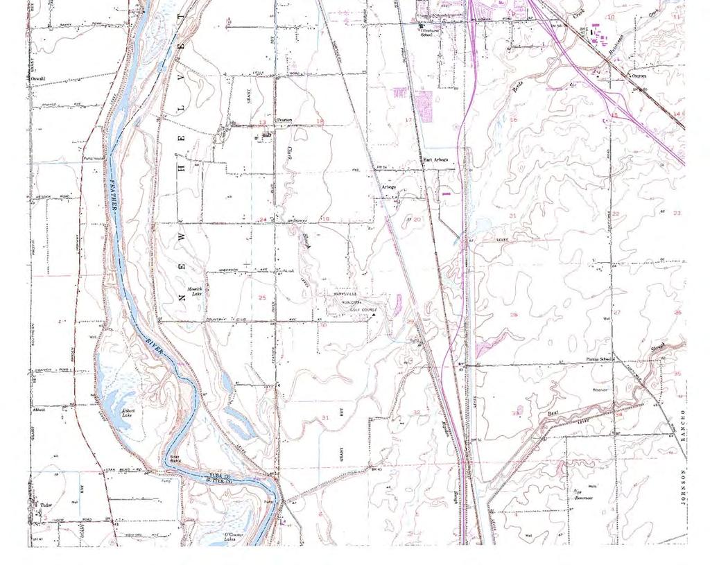
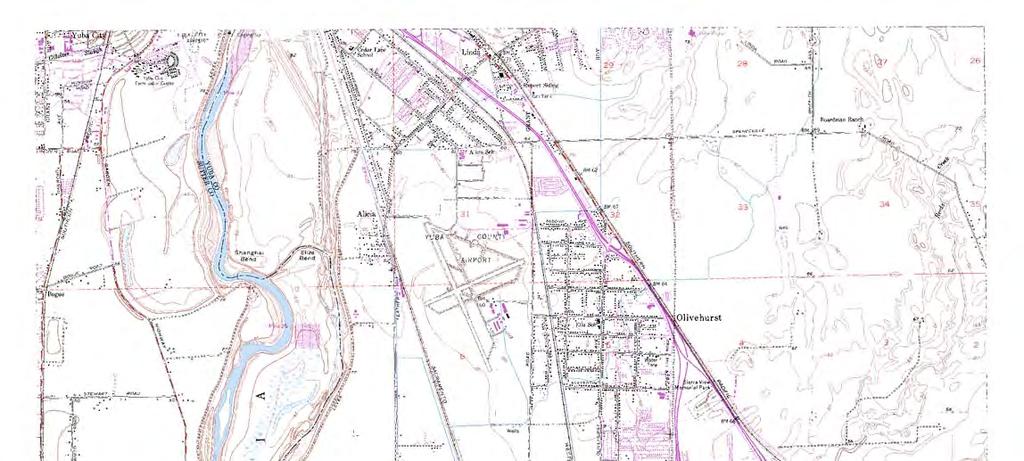
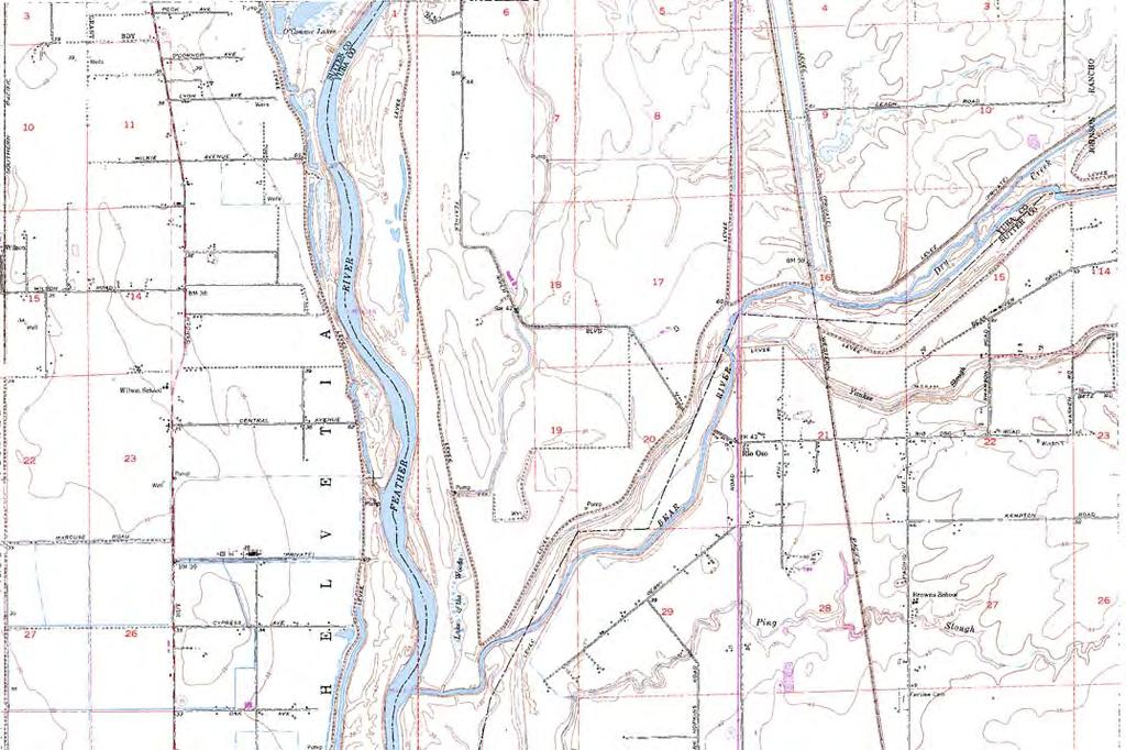
107
108 Appendix D Quality Assurance and Quality Control
109
110 Yuba South Levee (Simpson Lane to the Goldfields) Certification Summary Supplement Appendix B Embankment Protection (Engineer s Opinion immediately follows this page, Supporting Report separately bound)
111
112
113
114 Yuba South Levee (Simpson Lane to the Goldfields) Certification Summary Supplement Appendix C Embankment and Foundation Stability (Engineer s Opinion immediately follows this page, Supporting Report separately bound)
115
116
117
118 Yuba South Levee (Simpson Lane to the Goldfields) Certification Summary Supplement Appendix D Settlement (Engineer s Opinion immediately follows this page, Supporting Report separately bound)
119
120
121
122 Yuba South Levee (Simpson Lane to the Goldfields) Certification Summary Supplement Appendix E Interior Drainage Report (Engineer s Opinion immediately follows this page, Supporting Report separately bound)
123
124

125
126 Yuba South Levee (Simpson Lane to the Goldfields) Certification Summary Supplement Appendix F Operation & Maintenance Manual For RD 784 (Engineer s Opinion immediately follows this page, Supporting Report separately bound)
127
128 Engineer s Opinion Evaluation of the Operation and Maintenance Manuals Yuba River South Levee (Simpson Lane to the Goldfields) RD 784 Levee System This opinion (1) is made to assist the Three Rivers Levee Improvement Authority (TRLIA) in complying with the requirements, definitions and descriptions in the Code of Federal Regulations, Title 44 Emergency Management and Assistance, Part 65 Identification and Mapping of Special Hazard Areas and to support TRLIA s certification (2) of the Reclamation District 784 Levee System along the Yuba, Feather, and Bear Rivers and the Western Pacific Interceptor Canal. This opinion is limited to the base flood (i.e., 1-percent chance flood) for the specific areas listed below and is made to TRLIA. Additional information concerning this opinion can be located in the Corps of Engineers Standard Operation and Maintenance Manual for the Sacramento River Flood Control Project(May 1955), the Corps of Engineers Supplement to Standard Operation and Maintenance Manual, Sacramento River Flood Control Project, Unit No. 145-Part No. 1 (August 1955), TRLIA s Bear River Setback Levee, Addendum to: Supplement to Standard Operation and Maintenance Manual, Sacramento River Flood Control Project, Unit No. 145, Part No. 1, May 2007, TRLIA s Bear River North Levee, WPIC West Levee, and Yuba River South Levee, Addendum to: Supplement to Standard Operation and Maintenance Manual Sacramento River Flood Control Project, Unit No. 145 Part No. 1, January 2008, Revised March 2010 & June 2013 (Latest revision added the Upper Yuba Levee Improvement project features), and TRLIA s Feather River Levee Repair Project, Addendum to: Supplement to Standard Operation and Maintenance Manual, Sacramento River Flood Control Project, Unit No Part No. 1, October 2011 as identified. All information, calculations, definitions, descriptions, restrictions, limitations, and other pertinent data contained in these reports form the basis of this opinion. Appendix F Summary of Opinion: In accordance with paragraph (b) of 44 CFR 65.2 and based on the results of our evaluation of the Operation & Maintenance Manuals and Addendums for the RD 784 Levee System, it is our opinion that: 1. Data The data utilized in the preparation of the Addendums to the Supplemental Manual to the Standard SRFCP Operation & Maintenance Manual was obtained from many sources including the original manuals developed by USACE; design documents and plans for specific levee system alterations, guidance provided in various USACE and FEMA publications; RD 784 inspection, maintenance, and operational information; and information provided in HDR s, and Kleinfelder s levee investigations. To the best of our information, knowledge and belief, this data is accurate. November 2013 APPENDIX F Page 1 of 3
129 Engineer s Opinion Evaluation of the Operation and Maintenance Manuals Yuba River South Levee (Simpson Lane to the Goldfields) RD 784 Levee System 2. Analysis - Our analysis consisted of Review of available operation and maintenance manuals. Review of federal and state guidelines and regulations for the operation and maintenance of levee systems and interior drainage systems. Review of Design Documents and Construction Completion Reports for the different alterations completed for the RD 784 Levee System. Review and preparation of O&M manual addendums prepared for the recent levee alterations. Evaluation of recent state levee inspections of the RD 784 Levee System. Evaluation of how well the recent addendums provide appropriate operation and maintenance guidance for the recently altered Levee System. It is our opinion that this analysis was performed in accordance with sound engineering practices (3) appropriate to accurately assess adequacy of the operation and maintenance manuals and addendums being used for the RD 784 Levee System. 3. Structural Works- Not applicable for this Appendix. The "structural works" of the RD 784 Levee System was assessed in other appendices that are part of this submission to FEMA. 4. As-Built Conditions The Construction Documentation Report contains as-built drawings of the alterations and repairs made to this reach of levee. It also contains surveyed crest elevations along the length of the levee. It is our opinion that the Construction documentation Report meets FEMA requirements for providing as-built plans. November 2013 APPENDIX F Page 2 of 3


130 Engineer s Opinion Evaluation of the Operation and Maintenance Manuals Yuba River South Levee (Simpson Lane to the Goldfields) RD 784 Levee System Orin ion Offered by: Ric Reinhardt, PE MBK Engineers 1771 Tribute Road, Suite A Sacramento, CA Siqnature i//i /o s Date Not Valid Unless Stamoed 1 Consistent with current practice, these professional opinions of expected levee system performance are valid for 10 years from the date of the TRLIA certification. 2 Per 44 CFR (b),...a certification by a registered professional engineer or other party does not constitute a warranty or guarantee of performance, expressed, or implied. Certification of data is a statement that the data is accurate to the best of certifier s knowledge. Certification of analysis is a statement that the analyses have been performed correctly and in accordance with sound engineering practices. Certification of structural works is a statement that the works are designed in accordance with sound engineering practices to provide protection from the base flood. Certification of as built conditions is a statement that the structure(s) has been built according to the plans being certified, is in place, and is fully functioning. 3 It is assumed that sound engineering practices are practices that are performed in a manner consistent with the degree of skill and care ordinarily exercised by members of the profession currently practicing in the same locality under similar conditions. November 2013 APPENDIX F Page 3 of 3
131
132 Yuba South Levee (Simpson Lane to the Goldfields) Certification Summary Supplement Appendix G Quality Control Documents Board of Senior Consultants Credentials Board of Senior Consultants Quality Control Report
133
134 Donald H. Babbitt Faiz I. Makdisi David T. Williams Consultant AMEC Consultant 3860 West Land Park Drive 2101 Webster Street, 12 th Floor 2345 No. Co. Road 3 Sacramento, CA Oakland, CA Fort Collins, CO September 20, 2013 Mr. Larry Dacus MBK Engineers 1771 Tribute Road Sacramento, CA Subject: Three Rivers Levee Improvement Authority FEMA Certification Summary Supplement Reclamation District Upper Yuba South Levee (Simpson Lane to the Goldfields) Dear Mr. Dacus: At your request, we have conducted a quality assurance review of Three Rivers Levee Improvement Authority s Certification Summary Supplement, to the FEMA Certification Project, Yuba South Levee (Simpson Lane to the Goldfields). We, the undersigned, served as the Board of Senior Consultants (BOSC) during the design and construction of the repair for this reach of levee. The BOSC serves as the Independent External Review Panel for this project. We reviewed the draft summary report and engineering opinions and made cursory reviews of the following supporting documentation: MBK Engineers, Three Rivers Levee Improvement Authority Phase 4 Erosion Investigation, dated February Kleinfelder, Problem Identification Report, dated September 29, Upper Yuba Levee Improvement Project, Yuba River South Levee Evaluation, Simpson Lane to Yuba Gold Fields, Reclamation District No. 784, Yuba County, California MWH, Groundwater Impacts Evaluation Report, dated December Evaluation of Groundwater Impacts from the Upper Yuba River South Levee Repair Activities. Kleinfelder, Geotechnical Borrow Site Evaluation, dated June 10, 2010, Geotechnical Borrow site Evaluation TRLIA Borrow Area 1, Upper Yuba Levee Improvement Project, Yuba river south Levee Evaluation, Yuba county, California. This report provides an evaluation of quality and quantity of borrow material in the adjacent borrow site. Kleinfelder, Revised Geotechnical Basis of Design, dated June 11, Upper Yuba Levee Improvement Project, Yuba River South Levee Evaluation, Reclamation District 784, Yuba County, California. MBK, Hydraulic and Hydrologic Analysis Yuba River Patrol Road Levee, March HDR, Upper Yuba Levee Improvement Project, 100% Design Submittal Design Documentation Report, Upper Yuba Levee Improvement Project, Yuba River Basin, California (Sta to Sta ), dated June 21, MHM, Interior Drainage Study PAL Area Extension, LOMR Application Narrative East Linda Extension, August 10, 2010 (Revised September 17, 2010).
.")
135 Mr. Larry Dacus MBK Engineers September 20, 2013 Page 2 of 2 MBK, Bear River North Levee, WPIC West Levee, and Yuba River South Levee, Addendum to: Supplement to Standard Operation and Maintenance Manual Sacramento River Flood Control Project, Unit No. 145 Part No. 1, January 2008 (Revised March 2010, Revised June 2013). HDR, Construction Documentation Report, Upper Yuba Levee Improvement Project, Three Rivers Levee Improvement Authority, March MBK, Freeboard (Supplement), Yuba River South Levee in the Upper Yuba Levee Improvement Project, Three Rivers Levee Improvement Authority, May 17, We found that: The design teams had followed the standards of engineering practice required for design and construction of the repairs implemented in the Yuba South Levee (Simpson Lane to the Goldfields) reach of the RD 784 Levee System. Adequate and appropriate information had been gathered to perform the analyses needed to support the repairs implemented. The analyses performed were appropriate and were conducted correctly. The Construction Documentation Report for the repairs documents that the repairs had been constructed in accordance with the plans and specifications issued for construction, and satisfy the intent of the design. The references cited in the Certification Summary Report support the Engineers Opinion letters, and provide the appropriate and adequate information to support those opinions. Respectfully submitted, Donald H. Babbitt, P.E. Faiz I. Makdisi, P.E. David T. William, P.E. Board of Senior Consultants Board Senior of Consultants Board of Senior Consultants I:\Project\10000s\ \200-Year Flood Certification\2013 FEMA Certification Supplement Report_UYRLIP\BOSC Review Letter\FEMA Cert Supplement 2013_UYLIP_BOSC Review Letter_ docx
Port of Camas/Washougal Levee Recertification and Engineering Analysis Request for Proposal May 3, 2011
 I. Project Summary As part of their Map Modernization Program, FEMA has initiated a countywide Flood Insurance Study (FIS) and Digital Flood Insurance Rate Map (DFIRM) for the Port of Camas/Washougal.
NOTICE OF PREPARATION
 NOTICE OF PREPARATION Date: June 12, 2014 To: From: Subject: Governor s Office of Planning and Research/State Clearinghouse Unit, Responsible Agencies, Trustee Agencies, and Interested Parties Announcement
APPENDIX A. Project Scoping
 APPENDIX A Project Scoping Notice of Preparation To: From: Agencies and Interested Parties Paul Brunner, Executive Director, Three Rivers Levee Improvement Authority Date: June 13, 2006 Subject: Notice
American Water Resources Association Philadelphia Metropolitan Area Section
 American Water Resources Association Philadelphia Metropolitan Area Section Levee Evaluation and Certification under the NFIP November 18, 2010 Insert picture(s) here Agenda Background and Overview Flood
LEVEE DISTRICT NO. 1 OF SUTTER COUNTY
 LEVEE DISTRICT NO. 1 OF SUTTER COUNTY STAR BEND SETBACK LEVEE AND HABITAT ENHANCEMENT PROJECT BASIS OF DESIGN FEBRUARY 2009 Prepared By: TABLE OF CONTENTS QUALITY CONTROL CERTIFICATION... iv 1.0 INTRODUCTION...
TECHNICAL MEMORANDUM
 TECHNICAL MEMORANDUM SOIL SAMPLING, TESTING AND LOGGING ULOP GEOTECHNICAL EVALUATION STAR BEND SETBACK LEVEE Sutter County, California Prepared by: BLACKBURN CONSULTING 2491 Boatman Avenue West Sacramento,
PAPERWORK REDUCTION ACT A. GENERAL
 U.S. DEPARTMENT OF HOMELAND SECURITY - FEDERAL EMERGENCY MANAGEMENT AGENCY RIVERINE STRUCTURES FORM O.M.B No. 1660-0016 Expires: 12/31/2010 PAPERWORK REDUCTION ACT Public reporting burden for this form
Geotechnical Evaluation of a Small Levee System for FEMA Certification. Rebecca Money, PE, GE, CFM
 Geotechnical Evaluation of a Small Levee System for FEMA Certification Rebecca Money, PE, GE, CFM Purpose Provide an overview and an understanding for Cities/Counties/Districts of what it takes from a
ENGINEERING REPORT STRUCTURAL STABILITY ANALYSIS FLOODWALLS. HOUSATONIC RIVER and NAUGATUCK RIVER FLOOD PROTECTION PROJECTS SECTION 1
 ENGINEERING REPORT STRUCTURAL STABILITY ANALYSIS FLOODWALLS HOUSATONIC RIVER and NAUGATUCK RIVER FLOOD PROTECTION PROJECTS SECTION 1 ANSONIA and DERBY, CONNECTICUT December 2010 MMI #1560-119 and #3118-03
FEMA and Levees Levee Accreditation Reviews Proposed Changes to the FEMA Levee Policy
 Agenda FEMA and Levees Levee Accreditation Reviews Proposed Changes to the FEMA Levee Policy Page 2 FEMA and Levees FEMA and Levees FEMA does NOT own or operate any levees Establishment of appropriate
CONSTRUCTION PLAN CHECKLIST
 CONSTRUCTION PLAN CHECKLIST The design engineer is responsible for ensuring that plans submitted for city review are in accordance with this checklist. It is requested that the executed checklist be submitted
By Roger Churchwell San Joaquin Area Flood Control Agency.
 By Roger Churchwell San Joaquin Area Flood Control Agency www.sjafca.com Urban flood control facilities have preformed over the last 59 years Locally we are at the bottom of the bathtub Nearly 500,000
Paul Brunner, Larry Dacus, Doug Handen. Repairs to Concrete-Lined V-Ditch Alternatives Evaluation
 Memo To: Paul Brunner, Larry Dacus, Doug Handen From: Alberto Pujol /Dan Wanket Date: 09/10/2010 Re: Feather River Levee Site 7 Extension Repairs to Concrete-Lined V-Ditch Alternatives Evaluation This
Lower San Joaquin River Feasibility Study PLAN FORMULATION ADDENDUM
 PLAN FORMULATION ADDENDUM Non-Structural Measure Descriptions Elevate Critical Infrastructure This measure would raise at-risk critical structures above the design inundation level. Elevation would be
Chapter A-9 GEOTECHNICAL ANALYSIS NORTH KANSAS CITY - LOWER (HARLEM AREA)
") Kansas Citys, Missouri and Kansas Flood Damage Reduction Feasibility Study (Section 216 Review of Completed Civil Works Projects) Engineering Appendix to the Interim Feasibility Report Chapter A-9 GEOTECHNICAL
Kansas Citys, Missouri and Kansas Flood Damage Reduction Feasibility Study (Section 216 Review of Completed Civil Works Projects) Engineering Appendix to the Interim Feasibility Report Chapter A-9 GEOTECHNICAL
Chapter A-10 GEOTECHNICAL ANALYSIS NORTH KANSAS CITY - LOWER (NATIONAL STARCH AREA)
") Kansas Citys, Missouri and Kansas Flood Damage Reduction Feasibility Study (Section 216 Review of Completed Civil Works Projects) Engineering Appendix to the Interim Feasibility Report Chapter A-10 GEOTECHNICAL
Kansas Citys, Missouri and Kansas Flood Damage Reduction Feasibility Study (Section 216 Review of Completed Civil Works Projects) Engineering Appendix to the Interim Feasibility Report Chapter A-10 GEOTECHNICAL
Marysville Levee Commission
 Marysville Levee Commission Outline CVFPP Goals & Objectives Highlights of Draft Feather River RFMP Integration between Flood Protection, Agriculture and Wildlife and Floodplain Uses Proposed Projects
SAN GABRIEL RIVER/SAN JOSE CREEK 1 LEVEE SYSTEM LOS ANGELES COUNTY, CALIFORNIA NLD SYSTEM ID #
 SAN GABRIEL RIVER/SAN JOSE CREEK 1 LEVEE SYSTEM LOS ANGELES COUNTY, CALIFORNIA NLD SYSTEM ID # 3805010052 PERIODIC INSPECTION REPORT NO 1 GENERALIZED EXECUTIVE SUMMARY FINAL SYSTEM RATING: MINIMALLY ACCEPTABLE
Coal Combustion Residuals Unit Structural Stability Assessment
 Coal Combustion Residuals Unit Structural Stability Assessment Virginia Electric and Power Company Chesterfield Power Station Upper (East) Pond Chesterfield County, Virginia GAI Project Number: C1500035.00
CHAPTER 8 SEEPAGE CONTROL IN EMBANKMENTS
 CHAPTER 8 SEEPAGE CONTROL IN EMBANKMENTS 8-1. General. All earth and rock-fill dams are subject to seepage through the embankment, foundation, and abutments. Seepage control is necessary to prevent excessive
Flood Fighting and Surveillance
 Flood Fighting and Surveillance Don Moses Civil Engineer February 2016 US Army Corps of Engineers 1 Agenda Levee Design Common Failure Modes Surveillance/Inspection Flood Fighting 2 Levee Design Issues
SAN LUIS REY RIVER 3 LEVEE SYSTEM SAN DIEGO COUNTY, CALIFORNIA NLD SYSTEM ID #
 SAN DIEGO COUNTY, CALIFORNIA NLD SYSTEM ID # 3805010012 PERIODIC INSPECTION REPORT NO. 1 GENERALIZED EXECUTIVE SUMMARY FINAL SYSTEM RATING: UNACCEPTABLE FINAL RATING DATE: DECEMBER 15, 2017 PERIODIC INSPECTION
Regulation 18 August 2009 NO Operations and Maintenance LEVEE ENCROACHMENT STANDARDS AND PROCEDURES
 CENWP-EC DEPARTMENT OF THE ARMY PDR 30-2-5 Portland District, Corps of Engineers (Draft) P.O. Box 2946 Portland, Oregon 97208 Regulation 8 August 2009 NO. 30-2-5 Operations and Maintenance LEVEE ENCROACHMENT
Evaluation of Cutoff Walls Impact on Groundwater Recharge (Kleinfelder)
") C3 Evaluation of Cutoff Walls Impact on Groundwater Recharge (Kleinfelder) December 19, 2007 Revised April 21, 2009 File No.: 72834 Mr. Timothy Washburn SAFCA 1007 7th Street, 7th Floor Sacramento, CA
C3 Evaluation of Cutoff Walls Impact on Groundwater Recharge (Kleinfelder) December 19, 2007 Revised April 21, 2009 File No.: 72834 Mr. Timothy Washburn SAFCA 1007 7th Street, 7th Floor Sacramento, CA
Technical Memorandum Channel Capacity Report 2018 Restoration Year
 Technical Memorandum Channel Capacity Report 2018 Restoration Year 1 Table of Contents 2 1.0 Executive Summary... ES-1 3 4 2.0 Introduction... 1 5 2.1 Objective... 2 6 2.2 CCAG Roles and Responsibilities...
2 ALTERNATIVES 2.1 INTRODUCTION NEPA/CEQA REQUIREMENTS FOR EVALUATION OF ALTERNATIVES NEPA REQUIREMENTS
 2 ALTERNATIVES 2.1 INTRODUCTION As noted in Chapter 1, Introduction and Statement of Purpose and Need, this EIS/EIR has been prepared to evaluate the potential environmental impacts of the Phase 4b Project,
Technical Memorandum Public Draft Channel Capacity Report 2019 Restoration Year
 Public Draft Channel Capacity Report 2019 Restoration Year 1 Table of Contents 2 1.0 Executive Summary... 1 3 2.0 Introduction... 1 4 3.0 Study Area... 3 5 4.0 Completed Channel Capacity Studies and Related
M E M O R A N D U M. 1. PSOMAS position on vertical datum differences between NGVD29 and NAVD88 for the NLIP project (submitted by Brian Bullock:
 M E M O R A N D U M Date: August 5, 2009 Prepared by: SAFCA NLIP Consultants Purpose: Response to the request by the Board of Senior Consultants (BOSC) in Board Report No. 1; Initial Recommendations Following
Kansas Levee Certifications Assessments, Findings and Challenges. APWA Congress Denver, Co - Sept 18, 2011
 Kansas Levee Certifications Assessments, Findings and Challenges APWA Congress Denver, Co - Sept 18, 2011 Introductions Presenters Doug Danaher, PE, CFM Wilson and Company Joe File, PE, CFM AMEC Brian
AMERICAN ELECTRIC POWER (SWEPCO)
") 2016 DAM & DIKE INSPECTION REPORT ASH PONDS GERS-16-163 WELSH POWER PLANT AMERICAN ELECTRIC POWER (SWEPCO) CASON, TEXAS NATIONAL INVENTORY NO. TX4357 PREPARED BY GEOTECHNICAL ENGINEERING AEP SERVICE CORPORATION
2016 DAM & DIKE INSPECTION REPORT ASH PONDS GERS-16-163 WELSH POWER PLANT AMERICAN ELECTRIC POWER (SWEPCO) CASON, TEXAS NATIONAL INVENTORY NO. TX4357 PREPARED BY GEOTECHNICAL ENGINEERING AEP SERVICE CORPORATION
SLURRY WALLS FOR SEEPAGE CUTOFF IN LEVEE APPLICATIONS RECENT EXPERIENCE AND CONSTRUCTION CHALLENGES IN THE NORTHERN CENTRAL VALLEY OF CALIFORNIA
 SLURRY WALLS FOR SEEPAGE CUTOFF IN LEVEE APPLICATIONS RECENT EXPERIENCE AND CONSTRUCTION CHALLENGES IN THE NORTHERN CENTRAL VALLEY OF CALIFORNIA Deep Foundation Institute Slurry Wall Committee July 22,
Chapter A-13 STRUCTURAL ANALYSIS ARGENTINE RAISE
 Kansas Citys, Missouri and Kansas Flood Damage Reduction Feasibility Study (Section 216 Review of Completed Civil Works Projects) Engineering Appendix to the Interim Feasibility Report Chapter A-13 STRUCTURAL
LOS ANGELES RIVER/ COMPTON CREEK 2 LEVEE SYSTEM LOS ANGELES COUNTY, CALIFORNIA NLD SYSTEM ID #
 LOS ANGELES RIVER/ COMPTON CREEK 2 LEVEE SYSTEM LOS ANGELES COUNTY, CALIFORNIA NLD SYSTEM ID # 3805010033 PERIODIC INSPECTION REPORT NO. 2 GENERALIZED EXECUTIVE SUMMARY FINAL SYSTEM RATING: UNACCEPTABLE
INDIAN BEND WASH 2 LEVEE SYSTEM MARICOPA COUNTY, ARIZONA NLD SYSTEM ID #
 INDIAN BEND WASH 2 LEVEE SYSTEM MARICOPA COUNTY, ARIZONA NLD SYSTEM ID # 3805020008 PERIODIC INSPECTION REPORT NO. 1 GENERALIZED EXECUTIVE SUMMARY FINAL SYSTEM RATING: MINIMALLY ACCEPTABLE FINAL RATING
Data Collection Report draft
 Data Collection Report draft City of Houston, Minnesota Houston Levee Certification Phase I Report prepared by June 2, 2015 DATA COLLECTION REPORT PHASE I DATA COLLECTION AND REVIEW HOUSTON LEVEE CERTIFICATION
The Vegetation Challenge Sacramento, California August 28-29, 29, 2007
 The Vegetation Challenge Sacramento, California August 28-29, 29, 2007 David A. Pezza, P. E. U. S. Army Corps, Headquarters Engineering and Construction Chief, Civil Works Branch ASCE Civil Engineering
SANTA MARIA RIVER 3A LEVEE SEGMENT SANTA BARBARA COUNTY, CALIFORNIA NLD SYSTEM ID #
 SANTA MARIA RIVER 3A LEVEE SEGMENT SANTA BARBARA COUNTY, CALIFORNIA NLD SYSTEM ID # 3805010095 PERIODIC INSPECTION REPORT NO. 1 GENERALIZED EXECUTIVE SUMMARY FINAL SYSTEM RATING: MINIMALLY ACCEPTABLE FINAL
ENGINEERING REPORT ANALYSIS OF CLOSURES. HOUSATONIC RIVER and NAUGATUCK RIVER FLOOD PROTECTION PROJECTS SECTION 1. ANSONIA and DERBY, CONNECTICUT
 ENGINEERING REPORT ANALYSIS OF CLOSURES HOUSATONIC RIVER and NAUGATUCK RIVER FLOOD PROTECTION PROJECTS SECTION 1 ANSONIA and DERBY, CONNECTICUT December 2010 MMI #1560-119 and #3118-03 Prepared for: City
LOS ANGELES RIVER 7 LEVEE SYSTEM LOS ANGELES COUNTY, CALIFORNIA NLD SYSTEM ID #
 LOS ANGELES COUNTY, CALIFORNIA NLD SYSTEM ID # 3805010078 PERIODIC INSPECTION REPORT NO 1 GENERALIZED EXECUTIVE SUMMARY FINAL SYSTEM RATING: UNACCEPTABLE FINAL RATING DATE: AUGUST 26, 2015 PERIODIC INSPECTION
CITY OF JENKS EARTH CHANGE PERMIT APPLICATION
 CITY OF JENKS EARTH CHANGE PERMIT APPLICATION Any applicable State or Federal permits must be attached to this application or must be applied for with copies attached to this application if this permit
GRADING, FILL, EXCAVATION AND LANDSCAPING 2012 EDITION
 CHAPTER 23.105 GRADING, FILL, EXCAVATION AND LANDSCAPING 2012 EDITION Sections 23.105.101 General... 1 23.105.102 Definitions... 1 23.105.103 Permits required... 3 23.105.104 Hazards.... 4 23.105.105 Permit
5th Street Bridge Replacement Project Yuba City, California Location Hydraulic Study Report Bridge No. 18C0012
 EA 03-0L2324 Yuba City, California Location Hydraulic Study Report Submitted to: Prepared by: November 2012 Table of Contents Executive Summary... iii Acronyms... v 1 General Description... 1 1.1 Project
Via October Mr. William Neal, P.E. Technological Specialist DTE Electric Company One Energy Plaza Detroit, MI 48226
 17 October 2016 134 N. La Salle Street, Suite 300 Chicago, Illinois 60602 PH 312.658.0500 FAX 312.658.0576 www.geosyntec.com Via Email Mr. William Neal, P.E. Technological Specialist DTE Electric Company
Chapter A-15. CID-MO Structural Analysis
 Kansas Citys, Missouri and Kansas Flood Risk Management Feasibility Study Engineering Appendix to the Final Feasibility Study Chapter A-15 CID-MO Structural Analysis Chapter A-15 CID-MO Structural Analysis
DEPARTMENT OF THE ARMY U.S. ARMY CORPS OF ENGINEERS, SACRAMENTO DISTRICT 1325 J STREET SACRAMENTO CA PUBLIC NOTICE
 DEPARTMENT OF THE ARMY U.S. ARMY CORPS OF ENGINEERS, SACRAMENTO DISTRICT 1325 J STREET SACRAMENTO CA 95814-2922 Operations and Readiness Branch PUBLIC NOTICE REQUEST FOR PERMISSION TO MODIFY A U.S. ARMY
PRELIMINARY SHORELINE PROTECTION STUDY Parking Lot D to the JFK Library
 PREPARED FOR: UNIVERSITY OF MASSACHUSETTS BOSTON PRELIMINARY SHORELINE PROTECTION STUDY Parking Lot D to the JFK Library UNIVERSITY OF MASSACHUSETTS Boston, Massachusetts PREPARED BY: PARE CORPORATION
(b) The written request must include 5 components: 1 The Permit Review and Approval Process. (1) Step 1: Pre-Coordination.
 The written request must include 5 components: 1 The Permit Review and Approval Process. (1) Step 1: Pre-Coordination.") 1 The Permit Review and Approval Process The processing of a Section 408 Permit request begins with a written request from an applicant. Along with the written request, a permit application (attached)
1 The Permit Review and Approval Process The processing of a Section 408 Permit request begins with a written request from an applicant. Along with the written request, a permit application (attached)
COYOTE CREEK 3 LEVEE SYSTEM LOS ANGELES COUNTY AND ORANGE COUNTY, CALIFORNIA NLD SYSTEM ID #
 LOS ANGELES COUNTY AND ORANGE COUNTY, CALIFORNIA NLD SYSTEM ID # 3805010025 PERIODIC INSPECTION REPORT NO. 2 GENERALIZED EXECUTIVE SUMMARY FINAL SYSTEM RATING: MINIMALLY ACCEPTABLE FINAL RATING DATE: MARCH
Levee Improvement District No. 19 System Review Phase 1 Fort Bend County, Texas
 Levee Improvement District No. 19 Fort Bend County, Texas Prepared for: Fort Bend County Levee Improvement District No. 19 202 Century Square Blvd. Sugar Land, Texas 77478 Submitted by: Aptim Environmental
SAN GABRIEL RIVER 1 LEVEE SYSTEM LOS ANGELES COUNTY, CALIFORNIA NLD SYSTEM ID #
 LOS ANGELES COUNTY, CALIFORNIA NLD SYSTEM ID # 3805010031 PERIODIC INSPECTION REPORT NO. 2 GENERALIZED EXECUTIVE SUMMARY FINAL SYSTEM RATING: MINIMALLY ACCEPTABLE FINAL RATING DATE: APRIL 19, 2017 PERIODIC
BLOCKING AND FILLING SURFACE DRAINAGE DITCHES
 MINNESOTA WETLAND RESTORATION GUIDE BLOCKING AND FILLING SURFACE DRAINAGE DITCHES TECHNICAL GUIDANCE DOCUMENT Document No.: WRG 4A-1 Publication Date: 10/14/2015 Table of Contents Introduction Application
Technical Memorandum
 Tucson Office 3031 West Ina Road Tucson, AZ 85741 Tel 520.297.7723 Fax 520.297.7724 www.tetratech.com Technical Memorandum To: Kathy Arnold From: Greg Hemmen, P.E. Company: Rosemont Copper Company Date:
Lyon Creek Cedar Way Stormwater Detention Dam Operation and Maintenance Manual
 Lyon Creek Cedar Way Stormwater Detention Dam Operation and Maintenance Manual Prepared by: Mike Shaw Stormwater Program Manager City of Mountlake Terrace January 2010 Section I General Information This
COACHELLA VALLEY WATER DISTRICT GUIDELINE K-2 SLOPE (BANK) PROTECTION DESIGN GUIDANCE
 PROTECTION DESIGN GUIDANCE") COACHELLA VALLEY WATER DISTRICT GUIDELINE K-2 SLOPE (BANK) PROTECTION DESIGN GUIDANCE K.2.1 General Requirements The design and construction of slope protection works may be required for several types
COACHELLA VALLEY WATER DISTRICT GUIDELINE K-2 SLOPE (BANK) PROTECTION DESIGN GUIDANCE K.2.1 General Requirements The design and construction of slope protection works may be required for several types
LOCATION RESTRICTIONS SEISMIC IMPACT ZONES BASIN 6
 LOCATION RESTRICTIONS SEISMIC IMPACT ZONES BASIN 6 U.S. EPA Coal Combustion Residuals Rule Brunner Island Steam Electric Station East Manchester Township, York County, Pennsylvania PREPARED FOR: BRUNNER
Determination of Design Infiltration Rates for the Sizing of Infiltration based Green Infrastructure Facilities
 Determination of Design Infiltration Rates for the Sizing of Infiltration based Green Infrastructure Facilities 1 Introduction This document, developed by the San Francisco Public Utilities Commission
Jacobi, Toombs, and Lanz, Inc.
 Area 5: Blackiston Mill Road at Dead Man's Hollow Flooding Assessment Jacobi, Toombs, and Lanz, Inc. This document summarizes an assessment of drainage and flooding concerns and provides recommendations
Mr. Michael Malone CPS Energy 145 Navarro Street San Antonio, Texas Project No
 Environmental Resources Management January 13, 2017 Mr. Michael Malone 145 Navarro Street San Antonio, Texas 78205 Project No. 0352436 CityCentre Four 840 West Sam Houston Parkway North, Suite 600 Houston,
USACE LEVEE RISK ASSESSMENT PROCESS LESSONS LEARNED
 USACE LEVEE RISK ASSESSMENT PROCESS LESSONS LEARNED 1 237 237 237 217 217 217 200 200 200 80 119 27 252 174.59 255 255 255 0 0 0 163 163 163 131 132 122 239 65 53 110 135 120 112 92 56 62 102 130 102 56
DESIGN GRADING AND EROSION CONTROL A. Slope Criteria
 Section 5. DESIGN GRADING AND EROSION CONTROL A. Slope Criteria Earthen slopes shall conform to the following: Maximum slope should not be steeper than 6:1 (horizontal to vertical) unless protected from
Technical Memorandum No. 8 June 3, 2013 Page 2. FEMA Floodplain Mapping Flood Elevations at WWTP
 Page 2 FEMA Floodplain Mapping Flood Elevations at WWTP Existing Flood Control Facilities The City of Davis WWTP is located immediately north of the Willow Slough Bypass and west of the Yolo Bypass (see
Table of Contents 5.1 GENERAL Overview Investigation and Engineering Information
 Table of Contents Section Page 5.1 GENERAL... 5.1-1 5.1.1 Overview... 5.1-1 5.1.2 Investigation and Engineering Information... 5.1-2 5.2 PRELIMINARY GEOTECHNCIAL REPORTS... 5.2-1 5.2.1 Preliminary Geotechnical
Sacramento Area Flood Control Agency. May State Clearinghouse No Prepared for: Prepared by: Consulting Engineers and Scientists
 Addendum No. 3 (North Sacramento Streams) to the Environmental Impact Report on the North Sacramento Streams, Sacramento River East Levee, Lower American River, and Related Flood Improvements Project Prepared
Ponds. Pond A water impoundment made by excavating a pit, or constructing a dam or an embankment.
 POND SITE SELECTION AND CONSTRUCTION Uses, Planning, & Design David Krietemeyer Area Engineer USDA-NRCS June 20, 2008 Uses Considerations for Location of Commonly Used Terms Pond A water impoundment made
AMERICAN ELECTRIC POWER (SWEPCO)
") 2015 DAM & DIKE INSPECTION REPORT ASH PONDS GERS-15-034 WELSH POWER PLANT AMERICAN ELECTRIC POWER (SWEPCO) CASON, TEXAS NATIONAL INVENTORY NO. TX4357 PREPARED BY GEOTECHNICAL ENGINEERING AEP SERVICE CORPORATION
2015 DAM & DIKE INSPECTION REPORT ASH PONDS GERS-15-034 WELSH POWER PLANT AMERICAN ELECTRIC POWER (SWEPCO) CASON, TEXAS NATIONAL INVENTORY NO. TX4357 PREPARED BY GEOTECHNICAL ENGINEERING AEP SERVICE CORPORATION
TOWN OF MANCHESTER PLANNING AND ZONING COMMISSION Subdivision Application Minimum Submission Requirements
 TOWN OF MANCHESTER PLANNING AND ZONING COMMISSION Subdivision Application Minimum Submission Requirements This checklist is to be completed and submitted with all Subdivision Applications. The Town reserves
CCR Rule Operating Criteria Closure Plan
 CCR Rule Operating Criteria 257.102 Closure Plan FGD Pond 2 Jim Bridger Plant Point of Rocks, Wyoming PREPARED FOR PacifiCorp 1407 West North Temple Salt Lake City, UT 84116 (801) 521-0376 Fax (801) 220-4748
 Appendix B Example of the Tiered NEPA Document to be used for Categorically Permitted Alterations PROGRAMMATIC ENVIRONMENTAL ASSESSMENT CATEGORICAL PERMISSIONS SECTION 408 ALTERATIONS TO EXISTING U.S.
VISUAL SITE INSPECTION REPORT 2018
 VISUAL SITE INSPECTION REPORT 2018 SOUTHERN INDIANA GAS AND ELECTRIC A. B. BROWN GENERATING STATION TYPE III RESTRICTED WASTE LANDFILL WEST FRANKLIN, IN ATC PROJECT NO. 170LF00614 January 9, 2019 PREPARED
Civil Engineer USACE, Omaha District. 28 February 2017 FLOOD FIGHTING AND SURVEILLANCE
 217 FLOOD FIGHTING AND SURVEILLANCE 237 200 237 217 200 Don Moses, 237 P.E. 217 200 Civil Engineer USACE, Omaha District 255 0 163 131 255 0 163 132 255 0 163 122 28 February 2017 239 65 53 80 119 27 110
MILL CREEK LEVEE SYSTEM SAN BERNARDINO COUNTY, CALIFORNIA NLD SYSTEM ID #
 SAN BERNARDINO COUNTY, CALIFORNIA NLD SYSTEM ID # 3805010056 PERIODIC INSPECTION REPORT NO 1 GENERALIZED EXECUTIVE SUMMARY FINAL SYSTEM RATING: MINIMALLY ACCEPTABLE FINAL RATING DATE: SEPTEMBER 23, 2013
APPENDIX A. Hydraulic Investigations: Cascade Mall at Burlington
 APPENDIX A m SUMMARY REPORT FOR E.I.S. Hydraulic Investigations: Cascade Mall at Burlington July 12, 1982 John E. Norman, P.E. 14779 Northeast 32nd, #A201 Bellevue, WA 98007 (206) 882-1767 92 General A
Appendix B Stormwater Site Plan Submittal Requirements Checklist
 Stormwater Site Plan Submittal Requirements Checklist The Submittal Requirements Checklist is intended to aid the design engineer in preparing a Stormwater Site Plan. All items included in the following
An Introduction to Seepage, Slope and Settlement of Levees
 An Introduction to Seepage, Slope and Settlement of Levees Course No: G02-011 Credit: 2 PDH J. Paul Guyer, P.E., R.A., Fellow ASCE, Fellow AEI Continuing Education and Development, Inc. 9 Greyridge Farm
AGUA FRIA RIVER 5 LEVEE SYSTEM MARICOPA COUNTY, ARIZONA NLD SYSTEM ID #
 AGUA FRIA RIVER 5 LEVEE SYSTEM MARICOPA COUNTY, ARIZONA NLD SYSTEM ID # 3805020001 PERIODIC INSPECTION REPORT NO. 1 GENERALIZED EXECUTIVE SUMMARY FINAL SYSTEM RATING: MINIMALLY ACCEPTABLE FINAL RATING
4. FISH PASSAGE CONCEPTS
 Feasibility Study for Restoration of Titlow Lagoon Fish Passage South Puget Sound Salmon Enhancement Group 4. FISH PASSAGE CONCEPTS Fish passage could be improved by rehabilitating the existing fish passage,
FINDINGS OF FACT AND STATEMENT OF OVERRIDING CONSIDERATIONS
 WEST SACRAMENTO AREA FLOOD CONTROL AGENCY SOUTHPORT SACRAMENTO RIVER EARLY IMPLEMENTATION PROJECT (BORROW ONE PROJECT) FINDINGS OF FACT AND STATEMENT OF OVERRIDING CONSIDERATIONS P R E P A R E D F O R
LAKE COUNTY HYDROLOGY DESIGN STANDARDS
 LAKE COUNTY HYDROLOGY DESIGN STANDARDS Lake County Department of Public Works Water Resources Division 255 N. Forbes Street Lakeport, CA 95453 (707)263-2341 Adopted June 22, 1999 These Standards provide
UPPER MISSISSIPPI RIVER COMPREHENSIVE PLAN
 UPPER MISSISSIPPI RIVER COMPREHENSIVE PLAN APPENDIX D COST ESTIMATES Prepared by the U.S. Army Corps of Engineers Rock Island, St. Louis, and St. Paul Districts March 2008 UPPER MISSISSIPPI RIVER COMPREHENSIVE
Jim Bridger Power Plant
 2015 Coal Combustion Residuals Annual Inspection Jim Bridger Power Plant Industrial Landfill Prepared for PacifiCorp Energy North Temple Office 1407 West North Temple Salt Lake City, Utah 84116 Final December
Expert Engineering Independent Third-Party Review Briscoe-Desimone Levee Design Green River Basin State of Washington
 Expert Engineering Independent Third-Party Review Briscoe-Desimone Levee Design Green River Basin State of Washington Prepared for King County Flood Control District Prepared by Robert B. Gilbert, Ph.D.,
 Tiered NEPA Document for Categorically Permitted Alterations to Existing U.S. Army Corps of Engineer Civil Works Projects Proposed Categorically Permitted Alterations (Check all that apply) Utilities under
APPENDIX G DIVERSION AND PELICAN LAKE CUTOFF CHANNELS HYRAULICS AND BRIDGE TECHNICAL MEMORANDUM
 APPENDIX G DIVERSION AND PELICAN LAKE CUTOFF CHANNELS HYRAULICS AND BRIDGE TECHNICAL MEMORANDUM To: File Memo From: Matt Redington, P.E. Project: Watertown South Connector CC: Date: March 6, 2007; revised
VENTURA RIVER 1 LEVEE SYSTEM VENTURA COUNTY, CALIFORNIA NLD ID #
 VENTURA RIVER 1 LEVEE SYSTEM VENTURA COUNTY, CALIFORNIA NLD ID # 380510086 PERIODIC INSPECTION REPORT NO 1 GENERALIZED EXECUTIVE SUMMARY 8 JUNE 2012 FINAL RATING: MINIMALLY ACCEPTABLE FINAL RATING DATE:
August 15, 2006 (Revised) July 3, 2006 Project No A
 July 3, 2006 Project No A") August 15, 2006 (Revised) July 3, 2006 Project No. 01-05-0854-101A Mr. David Reed, P.E. Protean Design Group 100 East Pine Street, Suite 306 Orlando, Florida 32801 Preliminary Soil Survey Report Polk Parkway
August 15, 2006 (Revised) July 3, 2006 Project No. 01-05-0854-101A Mr. David Reed, P.E. Protean Design Group 100 East Pine Street, Suite 306 Orlando, Florida 32801 Preliminary Soil Survey Report Polk Parkway
Regional Vegetation Variance
 Paige Caldwell, P.E. Emergency Manager Overview Key points from the ETL guidance Vegetation variance authority and background Key points of variance guidance Next Steps Key points from the newly revised
FIRM NAME DESIGNER: CHECKER: DATE: FPID #: DESCRIPTION: COUNTY: DRAINAGE DESIGN CHECKLIST. Designers Initials. Checkers Initials.
 I. Drainage Report A. Executive Summary - Brief Overview of Project Drainage Design B. Project Description 1. Existing Conditions 2. Proposed Project Conditions 3. Project Justification Narrative - Basin
ROLES AND RESPONSIBILITIES Small Pond Approval. SWM MD-378 Pond Checklist Training 10/17/07. Exemptions EMBANKMENT HEIGHT. Height of Dam Weir Wall
 SWM MD-378 Pond Checklist Training 10/17/07 Ken Wolfe Warren Johnson USDA, NRCS Frederick, Maryland ROLES AND RESPONSIBILITIES Small Pond Approval MDE, WMA, Dam Safety Division Authority (COMAR 26.17.04.03)
ATTACHMENT 6 WATER QUALITY SWALE DESIGN ADDENDUM
 ATTACHMENT 6 WATER QUALITY SWALE DESIGN ADDENDUM 12 October 2010 Project No. 073-81694.0022 Mr. Robert R. Monok Project Manager Energy Fuels Resource Corporation 44 Union Boulevard, Suite 600 Lakewood,
DTE Energy St. Clair Power Plant
 DTE Energy St. Clair Power Plant Unit 6 Scrubber Basins CCR Rule Compliance Project Annual Inspection Report - 2017 Project Number: 60546402 June 30, 2017 Prepared by: 27777 Franklin Road, Suite 2000 Southfield,
ILLINOIS URBAN MANUAL PRACTICE STANDARD TEMPORARY STREAM CROSSING (no.) CODE 975. Source: Hey and Associates, Inc.
 CODE 975. Source: Hey and Associates, Inc.") ILLINOIS URBAN MANUAL PRACTICE STANDARD TEMPORARY STREAM CROSSING (no.) CODE 975 Source: Hey and Associates, Inc. DEFINITION A bridge or culvert crossing installed across a stream or watercourse for short-term
ILLINOIS URBAN MANUAL PRACTICE STANDARD TEMPORARY STREAM CROSSING (no.) CODE 975 Source: Hey and Associates, Inc. DEFINITION A bridge or culvert crossing installed across a stream or watercourse for short-term
East Garden Grove-Wintersburg Channel (OCFCD Facility No. C05) from upstream Warner Avenue to downstream Goldenwest Street.
 from upstream Warner Avenue to downstream Goldenwest Street.") Facility. C05) from upstream Warner Avenue to Lead Agency: Agency: Project Director: Address: Orange County, Public Works, Infrastructure Programs, Capital Programs Sam Ali 300 N. Flower Street Santa Ana
Facility. C05) from upstream Warner Avenue to Lead Agency: Agency: Project Director: Address: Orange County, Public Works, Infrastructure Programs, Capital Programs Sam Ali 300 N. Flower Street Santa Ana
Chapter 4. Drainage Report and Construction Drawing Submittal Requirements
 4.0 Introduction The requirements presented in this section shall be used to aid the design engineer or applicant in the preparation of drainage reports, drainage studies, and construction drawings for
McElroy s Run Impoundment Coal Combustion Residual Annual Report
 Allegheny Energy Supply Company, LLC A FirstEnergy Company Pleasants Power Station Pleasants County, West Virginia GAI Project Number: C150917.01 January 2016 Prepared for: Allegheny Energy Supply Company,
McElroy s Run Impoundment Structural Stability Assessment Report
 Allegheny Energy Supply Company, LLC A FirstEnergy Company Pleasants Power Station Pleasants County, West Virginia October 2016 Prepared for: Allegheny Energy Supply Company, LLC A FirstEnergy Company
STRUCTURAL STABILITY ASSESSMENT. Bremo Power Station CCR Surface Impoundment: North Ash Pond STRUCTURAL STABILITY ASSESSMENT
 STRUCTURAL STABILITY ASSESSMENT STRUCTURAL STABILITY ASSESSMENT Bremo Power Station CCR Surface Impoundment: North Ash Pond ~,Dominion Submitted To: Bremo Power Station 1038 Bremo Bluff Road Bremo Bluff,
Hydraulic and Sediment Transport Modeling Strategy
 Appendix B Hydraulic and Sediment Transport May 2014 Technical Memorandum Channel Capacity Report September 2014 San Joaquin River Restoration Program Hydraulic and Sediment Transport The San Joaquin River
 Risk Assessment of Proposed Remediation Methods Trinity River Corridor Dallas Floodway 2 November 2012 Table of Contents Introduction... 1 Alternatives Analysis Risk Assessment... 1 Project Authorization...
CCR Annual Inspection (b) for the Ash Pond at the A.B. Brown Generating Station. Revision 0
 for the Ash Pond at the A.B. Brown Generating Station. Revision 0") Submitted to Southern Indiana Gas & Electric Company dba Vectren Power Supply, Inc. (SIGECO) One Vectren Square Evansville, IN 47708 Submitted by AECOM 9400 Amberglen Boulevard Austin, Texas 78729 257.83
Submitted to Southern Indiana Gas & Electric Company dba Vectren Power Supply, Inc. (SIGECO) One Vectren Square Evansville, IN 47708 Submitted by AECOM 9400 Amberglen Boulevard Austin, Texas 78729 257.83
UPRR INDUSTRIAL LEAD BRIDGE T-WALL RETAINING WALL SYSTEM 5.0 x 7.5 UNITS DESIGN UNIT 018 WORK PACKAGE 04
 UPRR INDUSTRIAL LEAD BRIDGE T-WALL RETAINING WALL SYSTEM 5.0 x 7.5 UNITS DESIGN UNIT 018 WORK PACKAGE 04 1. Description This work shall consist of the design, manufacture and construction of a T-WALL structure