SMART GYPSUM STACK MANAGEMENT FROM CONCEPT TO REALITY
|
|
|
- Victoria Cole
- 6 years ago
- Views:
Transcription
1 SMART GYPSUM STACK MANAGEMENT FROM CONCEPT TO REALITY Phong Vo, Manager - Engineering/Gypsum, Mosaic Fertilizer, LLC Circa Crossing Drive Lithia, Florida 33547, USA and Ashraf H. Riad, Ph.D., P.E., Principal Engineer, Ardaman & Associates, Inc South Orange Avenue, Orlando, Florida 32809, USA Prepared for American Institute of Chemical Engineers Central Florida Section 4798 S. Florida Avenue, #253 Clearwater Conference June
2 ABSTRACT Phosphogypsum, a by-product from phosphoric acid production, is currently produced at Florida phosphoric production facilities at a rate of about 30 million tons per year. Current practice is to store the gypsum in engineered stacks. A typical gypsum stack covers an area of about 200 to 400 acres and is raised to heights up to 200 to 300 feet. Gypsum stacks are generally managed to safely contain the phosphogypsum (and process water) during the active life of the stack. Rainfall runoff from the top settling compartment(s) and from the active gypsum side slopes are comingled with process water and generally managed within the phosphogypsum stack pond system. After the stack reaches maturity, process water is removed by treatment or consumption, and the entire system is closed in a manner that clean rainfall runoff on the closed surfaces can be discharged off site through the permitted NPDES Outfalls. An overview of gypsum stack management using conventional method from inception to closure is presented. The conventional technique is compared to an alternative concept of smart gypsum stack management that allows for reduction of the watershed area during the active life of the gypsum stack. The authors will discuss technical challenges and regulatory constraints associated with the site and how solutions were developed to transfer the concept to reality over a six year period. The concept was successfully implemented which led to effective gypsum stack management, minimize environmental exposures, and realize significant cost savings. ii
3 TABLE OF CONTENTS ABSTRACT... iii BACKGROUND...2 CONVENTIONAL CONCEPT OF GYPSUM STACK MANAGEMENT...2 THE CONCEPT...4 NEW CONCEPT OF GYPSUM STACK MANAGEMENT...7 COMPARISON BETWEEN THE NEW AND CONVENTIONAL CONCEPT OF GYPSUM STACK MANAGEMENT...10 CONCLUSIONS...11 iii
4
5 LIST OF FIGURES Figure Page Aerial Photograph of Central Florida Showing Gypsum Stacks Conventional Phosphogypsum Stack Management Condition of Side Slopes Aerial photograph of Riverview Active Stack The Concept The Concept Typical Stack Cross-section with Side Slope Drains Alternative Decant System Interceptor Ditch Aerial Photograph Showing Completed Interceptor Ditch Side Slope Grading & Re-Vegetation Plan Aerial Photograph Showing Completion of the Concept Toe Swale Restoration - Typical Cross Section Photograph of Closed Toe Swale Smart Gypsum Stack Management System Looking South 1/2013 Aerial Photo Shown Completion of Closure CONCEPT. 11 1
6 SMART GYPSUM STACK MANAGEMENT FROM CONCEPT TO REALITY BACKGROUND Phosphogypsum, a by-product from phosphoric acid production, is currently produced at the phosphoric production facilities in Florida at a rate of about 30 million tons per year. The present practice is to store the gypsum in engineered stacks. Currently, there are over 25 gypsum stacks in central Florida at different stages (i.e., actively receiving phosphogypsum, inactive but not closed, under closure and fully closed). A 2012 aerial photograph of central Florida showing locations of various gypsum stacks is presented as Figure 1. Mosaic Fertilizer, LLC operates four chemical plants with gypsum stack systems in Central Florida and Louisiana. There are 16 gypsum stacks within Mosaic facilities in Florida and Louisiana at various stages of the stack lifecycle. CONVENTIONAL CONCEPT OF GYPSUM STACK MANAGEMENT A typical gypsum stack covers an area of about 200 to 400 acres and is raised to heights that can vary from about 200 feet to up to 300 feet. Gypsum stacks are generally managed to safely contain the phosphogypsum and associated process water during the active life of the stack. Different stages in the life cycle of a gypsum stack are illustrated on Figure 2 and are described below: 1. Inception. During this stage, the gypsum disposal area is prepared to receive gypsum slurry from the chemical plant. The base of the disposal area is graded and perimeter earthen containment dikes are constructed along with toe inspection roads and freshwater runoff collection ditches. The base of the disposal area is typically lined with a protective High Density Polyethylene (HDPE) liner system (except gypsum stacks constructed prior to the Florida Department of Environmental Protection (FDEP) Phosphogypsum Management Rules). A stack underdrain system is designed and installed above the liner in order to support the stack growth and maintain stability of the future side slopes of the stack. In addition to the underdrain system above the liner, some gypsum stack system requires underdrain system below the liner (due to hydrogeological conditions at the site) to control the water table below the liner and to prevent liner uplift until the gypsum stack is adequately 2
7 loaded with gypsum and process water. Gypsum discharge pipes and decant system are also placed within the disposal facility. 2. Startup. During this stage, gypsum slurry is discharged into the disposal facility. Prior to gypsum slurry discharge, the gypsum disposal area is often charged with adequate amount of process water to help managing gypsum depositions and gypsum beaches within the disposal area. The slurry discharge point and the decant system locations are optimized to efficiently develop rim ditches and starter dikes around the perimeter of the stack. An engineering and operation decision to have more than one settling compartment is typically made during this stage. 3. Active Stack. After developing rim ditches, seepage and runoff collection ditches at the toe of the stack, the gypsum stack is raised using the upstream method of construction along with rim ditching techniques. Depending on the condition of the facility and overall water balance, the stack is managed to maximize gypsum disposal while at the same time, optimize the process water storage within the stack compartments. Operational constraints (i.e., side slopes, minimum freeboard, crest road and inside gypsum roads, crest drainage, etc.) are typically mandated by the safety of the stack with regard to overtopping and slope stability and also regulatory constraints. One or more setback of the side slopes may be implemented based on the stack design to improve the stability and/or to reduce the side slope length in order to minimize erosion. 4. Mature Stack. The stack is considered at the mature stage when it reaches the design maximum height, and contains the maximum design gypsum storage volume. At this stage, the settling compartment on top of the stack is typically at the minimum ponded area required for clarification of decant water for the specific gypsum production. Ponded process water on top of the stack is managed within the system until closure starts. For most facilities, the life of the stack is typically designed to provide approximately 20 to 30 years of gypsum storage. During the life of the stack, minimal grading, if any, is performed on the side slopes or any intermediate benches. Side slopes are typically 2.5H: 1V for gypsum stacks in Florida and 6H: 1V for gypsum stacks in Louisiana. The top grade of the stack is typically bowl shaped with beaches around the perimeter. Gypsum grades on top of the stack are typically at 3% to 4% towards the middle of the stack. 5. Closure Stage I. After the stack retires and is ready for closure, the first closure stage is to remove the ponded water from the top of the stack. When the free water is removed from the top settling compartment, the phreatic surface on the side slopes starts to drop, allowing for closure of the side slopes. The drained free water must be consumed by treatment and discharged (or consumed in the plant if the plant is still active). During the 3
8 initial phase of settlement, a relatively large amount of seepage/consolidation process water will have to be consumed within a short period of time (about 6 to 12 months). 6. Closure Stage II. After draining the free water from the top of the settling compartment, the stack top gradient is prepared for closure. Construction activities include, excavating dewatering ditches spaced to efficiently dewater the gypsum surface in preparation for grading. The top of the stack is typically bowl-shaped with low points near the center of the pond. The top gradient is typically graded toward internal low points to follow the existing contours, thus minimizing earthwork. Stormwater is conveyed from the internal low points for controlled release. The top gradient is typically closed with an HDPE liner and 2-foot thick vegetated protective soil cover graded to promote drainage and minimize ponding of water on top of the final cover. 7. Closure Stage III. Following complete closure of the top of the stack (or during the closure period after draining ponded water), closure of side slopes of the stack begins. The side slopes of the stack are graded to provide smooth, uniform slopes minimizing earthwork and erosion. The side slope final cover typically consists of placing soil cover and grassing or amending the upper 12-inches of gypsum with dolomitic limestone, and grassing. Side slope drains are typically incorporated into the side slope closure to depress the water table within the stack slope and prevent seepage from exiting onto the surface of the slope. Stormwater runoff from the closed side slopes of the stack is collected within one or more side slope drainage swale(s) and within a toe drainage swale. The side slope and toe drainage swales are also lined with HDPE liner and covered with a 2-foot thick vegetated protective soil cover. 8. Closed Stack. After completion of closure of the top gradient of the stack, side slopes and toe drainage swales, the stack is considered closed stack. Stormwater runoff from the closed stack slopes are routed from the toe drainage swale for discharge through NPDES permitted outfall. Water quality is monitored for compliance with the permit requirements. Monitoring and maintenance activities for the closed stack top gradient and side slopes will be performed for the duration of the long term closure care period. THE CONCEPT Mosaic s Riverview Gypsum Stack System contains 736 acres of active footprint. The active gypsum stack was constructed and operated under a set of permits (Development 4
9 Orders and Florida Department of Environmental Protection) where Permit Conditions required grassing of the side slopes every 10 foot rise for meeting aesthetic look which is beyond the Florida Phosphogypsum Management Rules, Chapters and , F.A.C. In order to comply with the Permit Conditions, numerous repeated trials and large financial commitments to grass the side slope have been committed by the Company over the years but were not sustained successfully. As the gypsum stack increased in heights, pond acreage on top of the gypsum stack was reduced and additional side slope acreages were included in the stack system which creates additional challenges to protect the vegetated side slopes on the lower slopes from the acidic contaminated rainfall runoff from the upper slopes. Figure 3 shows an aerial photograph of the stack dated January Figures 3 and 4 illustrate the condition of the side slopes of the stack in The side slopes had sporadic vegetation and the toe swale appeared to contain process water. In order to overcome these challenges a concept was generated in 2007, supported by regulatory agencies (Florida Department of Environmental Protection FDEP & Environmental Protection Commission of Hillsborough County - EPCHC), and successfully implemented over a six year period. An illustration of the concept is shown on Figure 5. The concept required gradual approaches and critical steps (see Figure 6) such as defining the overall growth plan of the gypsum stack, redesign the decant system, identify and isolate the Inactive slopes from the active slopes with the Interceptor Ditch, inspect and repair the slope drain system, re-vegetate the side slopes, restore the contaminated toe swale, and isolate the underdrain systems within the swale. On May 2012, installation of The Concept was completed and allowed the Riverview facility to meet its permit obligations, rainfall runoff on the closed lower portion of the slope met the NPDES discharge criteria and was discharged off site, improved water balance for the facility, and eliminated over 130 acres of rainshed from the gypsum stack system nearly 30 years earlier than the end of life of the stack. Main features of operational and environmental issues of the Concept are discussed below: 1. Side Slope Drains. Side slope drains were installed along the perimeter of the stack in phases during the 2004/2006 period. The purpose of the side slopes drains is to depress the water table within the stack slope and prevent seepage from exiting on the surface of the slope see Figure Decant Process Water. The Riverview facility always used a siphon line for decanting process water from the top compartment of the stack to the cooling pond system. The siphon line was located at the southeast corner of the stack. Maintenance issues associated with crystal growth (see photo on Figure 8) during the cold periods necessitated that the pipe be periodically cut in small sections and 5
10 cleaned along the side slopes of the stack. An alternative decant system consisting of ditches, stilling basin, receiving basin and shorter decant pipe was designed and constructed in 2007/2008. The alternative decant system allows for decanting water from the top of the stack without affecting the side slopes (i.e., eliminating flow from siphon pipes on side slopes and/or eliminating pipe cleaning on the lower slopes), thus allowing for the closure of lower side slopes. Figure 8 shows layouts of the alternative decant system. 3. Interceptor Ditch. This is the key component of the concept. An interceptor ditch was constructed at about El 140 feet (NGVD) to collect and convey contaminated runoff and seepage from the upper active slopes to the cooling pond system. The interceptor ditch acts as a separator between the active and the inactive slopes. Figure 9 shows a photograph of the completed interceptor ditch. The alignment of the ditch is shown on Figure 10 with a 2009 aerial photograph. The interceptor ditch also provides a redundancy for environmental protection by intercepting and conveying any incidental spills from the top of the stack to the cooling ponds. 4. Grading and Grassing Side Slopes. The side slopes below Elevation 140 feet (NGVD) along the east, west and north side of the stack are approximately 100 acres. The side slopes on the south side are part of an expansion project and were not included in the closure project. The 100-acre side slope area was divided into 7 separate areas to control grading and grassing activities. Limits of the various areas are shown on a 2010 aerial photograph of the facility presented as Figure Restore Toe Swale for Conveying Clean Rainfall Runoff. The toe swale was originally designed and built with the intention to convey clean rainfall runoff from the closed side slopes. Due to the inability to close the side slopes and contain incidental spills the swale used to collect runoff from the side slopes of the stack and convey it to the cooling pond. Re-establishing a storm water swale was one of the critical steps of the Concept. Swale restoration involved capping all manholes and cleanouts of the stack underdrain system, removal of fine gypsum, installing a gravel underdrain system to collect seepage from the stack; grading the swale to provide positive drainage from the southeast corner to the southwest corner; lining the swale with HDPE liner covered with a 2-foot thick vegetated protective soil cover. Figure 12 shows an April 24, 2012 aerial photograph of the stack at the end of the swale restoration construction period. A cross section showing the closure design of the swale is shown on Figure 13. The Swale was divided into six sections using check dams and valves as redundant measures for environmental protections to contain any incidental spills from the upper slopes, failure in the drains or any other mishap in the runoff quality. The check dam closest to the outfall structure was provided with an 6
11 automatic ph meter and automatic shut-off valve. Any impacted water flow would be timely collected and pumped into the cooling pond. Photographs of the swale before closure and after closure are presented in Figure Outfall Structure. The outfall structure from the toe Swale to the NPDES outfall was provided with an automatic monitoring system, automatic shut-off valves, redundant manual valve, and quick connect port to pump any impacted water to the cooling pond system. This should prevent excursions of water from the system. NEW CONCEPT OF GYPSUM STACK MANAGEMENT With a proven concept, different stages in the life cycle of a gypsum stack can be modified as following (see Figure 15): 1. Inception. All activities during this stage are exactly the same as for the Inception stage of the conventional management system. The designer of the stack system must give additional thoughts to specific details that may affect early closure of slopes while raising the stack (i.e., location of the stack drain outlets, toe ditch elevations, side slopes setback, etc.). 2. Startup. This stage is also similar to the Startup stage mentioned above with extra care given to specific details that may affect the early closure of the slopes of the stack (i.e., invert elevations of the seepage and runoff collection ditches; number of compartments, method of decanting water and location of the decant structures, etc.). 3. Active Stack. Initial raising of the stack slopes using rim ditch techniques and upstream method of construction is similar to the conventional management system. However, the designer and the operator of the stack must decide on an initial side slope set back elevation, location of the interceptor ditch and the size of the interceptor ditch. The size/location of the Interceptor ditch is the key element of the concept and must be determined based on the optimization of the storage life of the gypsum stack footprint, proper prediction of the stack consolidation, stability of the dike system, contributing watershed of the active slopes, and operational issues of the gypsum stack system. 7
12 4. Simultaneous Active / Closure Stage I. During this stage, the stack will continue to be raised using the rim ditch techniques and the upstream method of construction (Active Slopes), while simultaneously preparing the lower slopes for closure (Inactive Slopes). The first Interceptor Ditch will be excavated on the scheduled setback. The interceptor ditch is designed to handle runoff from the design storm (typically 12-inch storm event) along with process water decant, when needed. a. Active Stage I. The active slopes of the stack will continue to be raised above the scheduled setback. The gypsum stack operator may excavate the interceptor ditch as part of operation activities. A slight modification in the operation to allow for use of a wider rim ditch could be implemented, if needed to reduce seepage into the side slopes of the stack. The Interceptor ditch must be operated, as designed, at the recommended operating water levels for the corresponding height of the stack. The depth of the interceptor ditch must be monitored for loss of capacity due to silting or settlement and corrective actions must be implemented. All other operation constraints which are similar to the conventional raising of the stack must be adhered to for safe operation of the stack. b. Closure Stage I. When the stack reaches the design height above the initial setback and the interceptor ditch, closure of the Inactive Slopes of the stack below the interceptor ditch begins. The design engineer should select the proper height above the interceptor ditch prior to start of closure activities. Selection of the proper design height above the interceptor ditch is based on many factors such as properties of the sedimented gypsum, piezometric water levels in the gypsum, settlement and consolidation behavior, permeability and seepage conditions, etc. The closure design features of the side slopes are similar to those described above. The design/ construction of the side slopes drains must consider performance of the drain at higher heights and age of gypsum, as well as additional seepage volumes from the future upper drains. At some instances, depending on the specific condition of the stack, the closure construction of the toe swale may need to be delayed until the grass is established on the side slopes and runoff quality improves. Automatic ph monitoring and diversion gates may have to be installed within the conveyance structures to control the direction of runoff flow. 5. Simultaneous Active / Closure Stage II. This stage can be a single or multiple stages depending on the maximum height of the stack, number of interceptor ditches, and design of the liner system and stack closure progress. Similarly to the previous stage, an additional setback and another interceptor ditch are installed to 8
13 separate the active from the inactive slopes. Closure of the inactive slopes is performed in accordance with a procedure similar to the previous stage. Additional concerns are listed below: a. Active Stage II. Changes to the side slope geometry and/or rim ditching techniques may have to be considered and implemented based on performance monitoring of the lower slopes (both active and closed). b. Closure Stage II. The closure of the inactive slopes will be performed in a similar way to the closure of the slopes described above. Stormwater runoff quality must be considered during the conveyance analyses to decide when and how to combine the runoff from the recent closed slopes to runoff from the established closed areas. Automatic ph monitoring and automatic diversion gates may have to be installed within the conveyance structures. 6. Mature Stack. When the stack reaches maturity under the Smart Gypsum Management Process, almost 70% of the stack side slopes should be completely closed as well as the intermediate ditches and toe swale. Moreover, hydraulic connection between the closed stack and the NPDES outfall should also completed and operational. 7. Final Closure Stage. The remaining closure activities after reaching a mature stack should be limited to less than 30% of the side slopes of the entire stack. The remaining closure activities can be performed simultaneously (i.e., closing the top of the stack prior to closing the remaining side slopes or vice versa). The final closure period is expected to be much shorter in duration than the closure period for stacks managed using the conventional method. Rainfall runoff and seepage volumes during the final closure period would also be a much smaller for stacks managed using the Smart Process. a. Final Closure A. Draining process water from top of the stack is performed similarly to the previously described activity with the exception that additional care must be exercised while transferring process water crossing closed slopes or ditches (e.g., use double lined pipes when crossing the closed areas.). b. Final Closure B. Closing the top of the stack is also similar process as described above with exceptions related to crossing the closed areas and excessive use of access ramps for construction equipment. 9
14 c. Final Closure C. Closure activities of the remaining active side slopes are similar to the previously described methodology, except that drains may have to be modified or eliminated based on the seepage pattern of the stack at the final closure time. The uppermost slope swale may be eliminated based on the engineering design and the remaining height of the stack at that time. 8. Closed Stack. Stormwater runoff from the closed stack slopes are routed from the toe drainage swale to the NPDES permitted outfall for offsite discharge. Water quality is monitored for compliance with the permit requirements. Monitoring and maintenance activities for the closed stack top gradient and side slopes will be performed for the duration of the long term closure care period. COMPARISIONS BETWEEN THE NEW & CONVENTIONAL CONCEPT ON GYPSUM STACK MANAGEMENT The following items summarizes major difference between the two Concepts 1. Safety. For a stack managed using the new concept, the side slopes drains are installed during the early stages of closure, thus improves the slope stability safety factor over a stack without side slopes drains (as in conventional management process). 2. Environmental Protections: the new concept will reduce environmental exposure by reducing the footprint of the gypsum stack system especially during the hurricane season. 3. Closure Construction Cost. For a stack managed using the new concept, closure cost is distributed over the life of the stack rather than during the initial few years after closure starts for the case of a stack managed using the conventional process. However some additional costs could be incurred with the new concept due to ongoing operational issues of the gypsum stack system and sizing of the drain system. 4. Operability of the Gypsum Stack System: Without a complete evaluation, the new concept can create interferences with the operability of the gypsum stack system such as return water conveying issues, gypsum stacking, and access roads. 10
15 5. Cost of Water Treatment, Water Balance and Pond Inventory Management. With the new concept, it is anticipated that the pond inventory will be significantly reduced due to early reduction of land surface footprint which will translate into lower costs in pond water management, lower water treatment costs, and improving the overall water balance of the facility. Early elimination of one hundred and thirty acres (130) of land surface from the gypsum stack system footprint on this Project allows the facility to avoid pond inventory gain from 60 to120 million gallons per year for the next 30 years (assuming 52 inches per year of normal rainfall). 6. Closure Period. The new concept should reduce the closure period after the stack reaches maturity because much of the stack has already been closed. 7. Aesthetics. A gypsum stack operated using the new concept has a better aesthetics for the surrounding communities than a stack operated using the conventional method, thus resulting in more favorable acceptance by public. 8. Closure Design and Construction for slopes while the stack is being raised should incorporate additional safety measures with regards to depressing water levels beneath the slopes, grassing methods, process water and freshwater conveyance among other closure design items. 9. Monitoring and Maintenance. With the new concept closure monitoring programs and maintenance activities must be implemented earlier than the conventional concept. 10. Permitting and Regulatory Obligations. The new concept allows the Riverview Facility to meet its permit obligations. CONCLUSIONS A new concept of gypsum stack management that allows for early reduction of the watershed areas during the active life of the gypsum stack was introduced. A proven case history that successfully implemented the new concept at the Mosaic Riverview Facility (see Figure 16) was reviewed. The new concept of gypsum stack management can be very effective in terms of gypsum stack closure costs, safety improvements, and environmental protection when the following elements are carefully considered: proper planning and design, maintain strict discipline on benching, proper growth projections and monitoring of consolidation progress, proper approaches on construction sequences, and continuous monitoring and maintenance of the closed areas. 11
16 12
 2012 Aerial")


17 5/10/2013 ( 11 Miles West) 2012 Aerial Photograph of Central Florida Showing Gypsum Stacks Figure 1 4 Mature Stack: Stack reached maximum capacity 5 Closure Stage I: Draining Processed Water from Top of Stack Closure Stage II: Lining/Closure of Top of Stack 6 3 ACTIVE STACK: Raising Stack using Rim Ditch/Upstream Method CONVENTIAL PHOSPHOGYPSUM STACK MANAGEMENT Closure Stage III: ClosingSide Slopes & Perimeter Dikes 7 2 STARTUP: Developing Rim Ditches, Gypsum Dikes & Compartments INCEPTION: Installing Liner, Drain & Perimeter Containment Dikes 1 Closed Stack: Runoff to NPDES outfalls Conventional Phosphogypsum Stack Management Figure 2 8 1


18 5/10/2013 Gypsum Stack Settling Pond side slope without grass Contaminated runoff Siphon line to Decant Process Water to Cooling Ponds Grassed side slope Cooling Ponds Swale Figure Condition of Side Slopes SOURCE: GOOGLE, INC. UNDER LICENSE BY ARDAMAN & ASSOCIATES, INC. USING GOOGLE EARTH PROFESSIONAL Toe Swale Rim Ditch Active Gypsum Stack Vegetated Side Slopes 2008 Aerial photograph of Riverview Active Stack Figure 4 2


19 5/10/2013 Gypsum Stack Modified Siphon line & Decant Open Ditch Contaminated runoff Interceptor Ditch Active side slope Clean runoff Closed Side Slope Swale Clean Storm water Runoff to Permitted Outfall Figure The Concept SOURCE: GOOGLE, INC. UNDER LICENSE BY ARDAMAN & ASSOCIATES, INC. USING GOOGLE EARTH PROFESSIONAL Swale to Restore Install Interceptor Ditch Existing Rim Ditch Active Gypsum Stack New Decant System Side Slopes to be Re-Vegetated The Concept SOURCE: GOOGLE, INC. UNDER LICENSE BY ARDAMAN & ASSOCIATES, INC. USING GOOGLE EARTH PROFESSIONAL Figure 6 3


20 5/10/2013 Typical Stack Cross-section with Side Slope Drains Figure 7 Alternative Decant System Figure 8 4


21 5/10/2013 Interceptor Ditch Figure 9 Interceptor Ditch SOURCE: GOOGLE, INC. UNDER LICENSE BY ARDAMAN & ASSOCIATES, INC. USING GOOGLE EARTH PROFESSIONAL Interceptor Ditch 2009 Aerial Photograph Showing Completed Interceptor Ditch Figure 10 5


22 5/10/2013 SOURCE: GOOGLE, INC. UNDER LICENSE BY ARDAMAN & ASSOCIATES, INC. USING GOOGLE EARTH PROFESSIONAL II I III IV V VI VII Figure 11 Side Slope Grading & Re-Vegetation Plan Permitted Outfall SOURCE: GOOGLE, INC. UNDER LICENSE BY ARDAMAN & ASSOCIATES, INC. USING GOOGLE EARTH PROFESSIONAL Clean Storm Water Runoff: Seepage & Contaminated Storm Water Runoff: 2012 Aerial Photograph Showing Completion of the Concept Figure 12 6


23 5/10/2013 Toe Swale Restoration - Typical Cross Section Figure 13 Photograph of Closed Toe Swale Figure 14 7


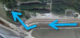
24 5/10/2013 Active Stack Stage I 4 Simultaneous Active / Closure Stage I Active Stack Stage II Closure Stage I 5 Simultaneous Active / Closure Stage II Closure Stage II Mature Stack: Stack reached maximum capacity 6 3 ACTIVE STACK: Raising Stack using Rim Ditch/Upstream Method SMART PHOSPHOGYPSUM STACK MANAGEMENT Final Closure A Drain Top Final Closure B Close Top Final Closure C Close side slope Final Closure Stage 7 2 STARTUP: Developing Rim Ditches, Compartments & Perimeter Ditches INCEPTION: Installing Liner, Drain & Perimeter Containment Dikes 1 Closed Stack: Runoff to NPDES outfalls Smart Gypsum Stack Management System Figure 15 8 Looking South 1/2013 Aerial Photo Shown Completion of Closure CONCEPT Figure 16 8
INFLOW DESIGN FLOOD CONTROL SYSTEM PLAN 40 C.F.R. PART PLANT BOWEN ASH POND 1 (AP-1) GEORGIA POWER COMPANY
 GEORGIA POWER COMPANY") INFLOW DESIGN FLOOD CONTROL SYSTEM PLAN 40 C.F.R. PART 257.82 PLANT BOWEN ASH POND 1 (AP-1) GEORGIA POWER COMPANY EPA s Disposal of Coal Combustion Residuals from Electric Utilities Final Rule (40 C.F.R.
INFLOW DESIGN FLOOD CONTROL SYSTEM PLAN 40 C.F.R. PART 257.82 PLANT BOWEN ASH POND 1 (AP-1) GEORGIA POWER COMPANY EPA s Disposal of Coal Combustion Residuals from Electric Utilities Final Rule (40 C.F.R.
VISUAL SITE INSPECTION REPORT 2018
 VISUAL SITE INSPECTION REPORT 2018 SOUTHERN INDIANA GAS AND ELECTRIC A. B. BROWN GENERATING STATION TYPE III RESTRICTED WASTE LANDFILL WEST FRANKLIN, IN ATC PROJECT NO. 170LF00614 January 9, 2019 PREPARED
GRADING, EROSION AND SEDIMENTATION CONTROL
 SECTION 500 GRADING, EROSION AND SEDIMENTATION CONTROL 501 Erosion and Sedimentation Control Plan All engineering plans for projects that propose to construct new, or modify existing drainage facilities,
2015 LANDFILL INSPECTION REPORT CARDINAL PLANT BRILLIANT, OHIO
 2015 LANDFILL INSPECTION REPORT GERS-15-021 CARDINAL PLANT BRILLIANT, OHIO PREPARED BY GEOTECHNICAL ENGINEERING AEP SERVICE CORPORATION 1 RIVERSIDE PLAZA COLUMBUS, OHIO Cardinal Plant Landfill Inspection
INITIAL RUN-ON AND RUN-OFF CONTROL PLAN 40 C.F.R. PART 257
 INITIAL RUN-ON AND RUN-OFF CONTROL PLAN 40 C.F.R. PART 257.81 PLANT BOWEN PRIVATE INDUSTRY SOLID WASTE DISPOSAL FACILITY (ASH LANDFILL) GEORGIA POWER COMPANY EPA s Disposal of Coal Combustion Residuals
INITIAL INFLOW DESIGN FLOOD CONTROL SYSTEM PLAN PLANT MCMANUS ASH POND A (AP-1) 40 CFR
 40 CFR") INITIAL INFLOW DESIGN FLOOD CONTROL SYSTEM PLAN PLANT MCMANUS ASH POND A (AP-1) 40 CFR 257.82 EPA s Disposal of Coal Combustion Residuals from Electric Utilities Final Rule (40 C.F.R. Part 257 and Part
INITIAL INFLOW DESIGN FLOOD CONTROL SYSTEM PLAN PLANT MCMANUS ASH POND A (AP-1) 40 CFR 257.82 EPA s Disposal of Coal Combustion Residuals from Electric Utilities Final Rule (40 C.F.R. Part 257 and Part
Pond Closure - Case Study[TP1]
![Pond Closure - Case Study[TP1]](/thumbs/94/122325712.jpg "Pond Closure - Case Study[TP1]") 2017 World of Coal Ash (WOCA) Conference in Lexington, KY - May 9-11, 2017 http://www.flyash.info/ Pond Closure - Case Study[TP1] By Pedro J Amaya, P.E. (1) (1) Civil Engineering and Geotechnical Engineering
2017 World of Coal Ash (WOCA) Conference in Lexington, KY - May 9-11, 2017 http://www.flyash.info/ Pond Closure - Case Study[TP1] By Pedro J Amaya, P.E. (1) (1) Civil Engineering and Geotechnical Engineering
POST CLOSURE PLAN. CFR (d) Pond 1. Clinch Power Plant Russell County, West Virginia. November Prepared for: Appalachian Power Company
 Pond 1. Clinch Power Plant Russell County, West Virginia. November Prepared for: Appalachian Power Company") POST CLOSURE PLAN CFR 257.104(d) Pond 1 Clinch Power Plant Russell County, West Virginia November 2016 Prepared for: Appalachian Power Company Prepared by: Amec Foster Wheeler Environment & Infrastructure,
POST CLOSURE PLAN CFR 257.104(d) Pond 1 Clinch Power Plant Russell County, West Virginia November 2016 Prepared for: Appalachian Power Company Prepared by: Amec Foster Wheeler Environment & Infrastructure,
2016 LANDFILL INSPECTION REPORT CARDINAL PLANT BRILLIANT, OHIO
 2016 LANDFILL INSPECTION REPORT GERS-16-004 CARDINAL PLANT BRILLIANT, OHIO PREPARED BY GEOTECHNICAL ENGINEERING AEP SERVICE CORPORATION 1 RIVERSIDE PLAZA COLUMBUS, OHIO Cardinal Plant Landfill Inspection
INITIAL RUN-ON AND RUN-OFF CONTROL PLAN 40 C.F.R. PART 257
 INITIAL RUN-ON AND RUN-OFF CONTROL PLAN 40 C.F.R. PART 257.81 HUFFAKER ROAD (PLANT HAMMOND) PRIVATE INDUSTRIAL LANDFILL (HUFFAKER ROAD LANDFILL) GEORGIA POWER COMPANY EPA s Disposal of Coal Combustion
INFLOW DESIGN FLOOD CONTROL SYSTEM PLAN PLANT GASTON GYPSUM POND ALABAMA POWER COMPANY
 INFLOW DESIGN FLOOD CONTROL SYSTEM PLAN PLANT GASTON GYPSUM POND ALABAMA POWER COMPANY Section 257.82 of EPA s regulations requires the owner or operator of an existing or new CCR surface impoundment or
Leachate Management Plan
 Leachate Management Plan LEACHATE MANAGEMENT PLAN Chesapeake Energy Center Ash Landfill Permit #440 Submitted To: Dominion Chesapeake Energy Center 2701 Vepco Street Chesapeake, Virginia 23323 Submitted
2015 ANNUAL ENGINEERING INSPECTION REPORT ENTERGY INDEPENDENCE PLANT CLASS 3N LANDFILL PERMIT NO S3N-R2 AFIN:
 2015 ANNUAL ENGINEERING INSPECTION REPORT ENTERGY INDEPENDENCE PLANT CLASS 3N LANDFILL PERMIT NO. 0200-S3N-R2 AFIN: 32-00042 JANUARY 15, 2016 ENTERGY INDEPENDENCE PLANT CLASS 3N LANDFILL 2015 ANNUAL ENGINEERING
City of Doral 8401 NW 53 rd Ter. Doral, FL 33166
 City of Doral 8401 NW 53 rd Ter. Doral, FL 33166 Project Address: (305) 593-6700 Permit Number: National Pollution Discharge Elimination System (NPDES) Construction Site Erosion and Sedimentation Control
CCR Rule Operating Criteria Closure Plan
 CCR Rule Operating Criteria 257.102 Closure Plan FGD Pond 2 Jim Bridger Plant Point of Rocks, Wyoming PREPARED FOR PacifiCorp 1407 West North Temple Salt Lake City, UT 84116 (801) 521-0376 Fax (801) 220-4748
Inspection Report. David Burton, Facility Manager (NRG Indian River Generating Station)
") Inspection Report To: From: David Burton, Facility Manager (NRG Indian River Generating Station) Richard Southorn, P.E., P.G., CPSWQ Re: Indian River Landfill Annual CCR Unit Inspection Report No. 2 Inspection
Inspection Report To: From: David Burton, Facility Manager (NRG Indian River Generating Station) Richard Southorn, P.E., P.G., CPSWQ Re: Indian River Landfill Annual CCR Unit Inspection Report No. 2 Inspection
Page 1 of 6 Permit No: MN R J. Mineral Mining and Dressing
 Page 1 of 6 J. Mineral Mining and Dressing 1. Authorized Stormwater Discharges The requirements in Sector J apply to stormwater discharges associated with industrial activity from active, temporarily inactive
C-1. Infiltration System
 C-1. Infiltration System Design Objective An infiltration system captures surface stormwater runoff and allows it to infiltrate into the soil. This SCM is typically the work horse of a runoff volume match
AMERICAN ELECTRIC POWER (SWEPCO)
") 2016 DAM & DIKE INSPECTION REPORT ASH PONDS GERS-16-163 WELSH POWER PLANT AMERICAN ELECTRIC POWER (SWEPCO) CASON, TEXAS NATIONAL INVENTORY NO. TX4357 PREPARED BY GEOTECHNICAL ENGINEERING AEP SERVICE CORPORATION
2016 DAM & DIKE INSPECTION REPORT ASH PONDS GERS-16-163 WELSH POWER PLANT AMERICAN ELECTRIC POWER (SWEPCO) CASON, TEXAS NATIONAL INVENTORY NO. TX4357 PREPARED BY GEOTECHNICAL ENGINEERING AEP SERVICE CORPORATION
2017 ANNUAL ENGINEERING INSPECTION REPORT ENTERGY INDEPENDENCE PLANT CLASS 3N LANDFILL PERMIT NO S3N-R2 AFIN:
 217 ANNUAL ENGINEERING INSPECTION REPORT ENTERGY INDEPENDENCE PLANT CLASS 3N LANDFILL PERMIT NO. 2-S3N-R2 AFIN: 32-42 JANUARY 17, 218 217 Landfill Inspection Report Entergy Independence Plant Class 3N
Coal Combustion Residuals Inflow Design Flood Control System Plan
 gaiconsultants.com I transforming ideas into reality., Coal Combustion Residuals Inflow Design Flood Control System Plan Virginia Electric and Power Company Possum Point Power Station Surface Impoundment
HISTORY OF CONSTRUCTION 40 CFR (c)(1)(i) (xii) PLANT HAMMOND ASH POND (AP 2) GEEORGIA POWER COMPANY
(1)(i) (xii) PLANT HAMMOND ASH POND (AP 2) GEEORGIA POWER COMPANY") HISTORY OF CONSTRUCTION 40 CFR 257.73(c)(1)(i) (xii) PLANT HAMMOND ASH POND (AP 2) GEEORGIA POWER COMPANY (i) Site Name and Ownership Information: Site Name: Plant Hammond Site Location: Site Address:
HISTORY OF CONSTRUCTION 40 CFR 257.73(c)(1)(i) (xii) PLANT HAMMOND ASH POND (AP 2) GEEORGIA POWER COMPANY (i) Site Name and Ownership Information: Site Name: Plant Hammond Site Location: Site Address:
Schedule A DISTRICT OF MAPLE RIDGE Watercourse Protection Bylaw
 Schedule A DISTRICT OF MAPLE RIDGE Watercourse Protection Bylaw 6410 2006 The Erosion and Sediment Control plan should seek (i) to protect the soil surface from erosion where possible and (ii) capture
Stormwater Erosion Control & Post-Construction Plans (Stormwater Quality Plans)
") Stormwater Erosion Control & Post-Construction Plans (Stormwater Quality Plans) Allen County Stormwater Plan Submittal Checklist The following items must be provided when applying for an Allen County Stormwater
Stormwater Erosion Control & Post-Construction Plans (Stormwater Quality Plans) Allen County Stormwater Plan Submittal Checklist The following items must be provided when applying for an Allen County Stormwater
NEW CASTLE CONSERVATION DISTRICT. through. (Name of Municipality) PLAN REVIEW APPLICATION DRAINAGE, STORMWATER MANAGEMENT, EROSION & SEDIMENT CONTROL
 PLAN REVIEW APPLICATION DRAINAGE, STORMWATER MANAGEMENT, EROSION & SEDIMENT CONTROL") NEW CASTLE CONSERVATION DISTRICT through (Name of Municipality) PLAN REVIEW APPLICATION DRAINAGE, STORMWATER MANAGEMENT, EROSION & SEDIMENT CONTROL Office use only: Received by Municipality: Received by
NEW CASTLE CONSERVATION DISTRICT through (Name of Municipality) PLAN REVIEW APPLICATION DRAINAGE, STORMWATER MANAGEMENT, EROSION & SEDIMENT CONTROL Office use only: Received by Municipality: Received by
ASH FILTER PONDS INFLOW DESIGN FLOOD CONTROL SYSTEM INITIAL PLAN
 CCR RULE COMPLIANCE ASH FILTER PONDS INFLOW DESIGN FLOOD CONTROL SYSTEM INITIAL PLAN Prepared for: GenOn Northeast Management Company Keystone Generating Station Shelocta, Pennsylvania Prepared by: CB&I
PEARCE CREEK CONFINED DISPOSAL AREA MODIFICATION
 US Army Corps of Engineers Philadelphia District PEARCE CREEK CONFINED DISPOSAL AREA MODIFICATION CECIL COUNTY MARYLAND STORMWATER MANAGEMENT PLAN NARRATIVE INITIAL SUBMISSION JUNE 2014 1 PEARCE CREEK
TABLE OF CONTENTS LEGAL NOTICE
 Surface Impoundments Page No. i TABLE OF CONTENTS 1. INTRODUCTION... 1 2. PROPOSED CCR IMPOUNDMENT CLOSURE PROCEDURE... 3 3. PROPOSED COVER SYSTEM... 4 4. ESTIMATED MAXIMUM INVENTORY OF CCR... 4 5. ESTIMATED
Description. Installation and Implementation Requirements
 Earth Dike SC-6 Source: Caltrans Construction Site Best Management Practices Manual, 2003. Description Structure that prevents erosion by intercepting, diverting, and conveying surface run-on (storm water
SC-01 Surface Outlet and Baffle Sediment Basin
 Greenville County Technical Specification for: SC-01 Surface Outlet and Baffle Sediment Basin 1.0 Surface Outlet and Baffle Sediment Basin This Specification contains requirements for the design and construction
RUN-ON AND RUN-OFF CONTROL PLAN 40 C.F.R. PART PLANT DANIEL NORTH ASH MANAGEMENT UNIT MISSISSIPPI POWER COMPANY
 RUN-ON AND RUN-OFF CONTROL PLAN 40 C.F.R. PART 257.81 PLANT DANIEL NORTH ASH MANAGEMENT UNIT MISSISSIPPI POWER COMPANY EPA s Disposal of Coal Combustion Residuals from Electric Utilities Final Rule (40
Report. Inflow Design Flood Control System Plan Belle River Power Plant East China, Michigan. DTE Energy Company One Energy Plaza, Detroit, MI
 Report Inflow Design Flood Control System Plan Belle River Power Plant East China, Michigan DTE Energy Company One Energy Plaza, Detroit, MI October 14, 2016 NTH Project No. 62-160047-04 NTH Consultants,
VISUAL SITE INSPECTION REPORT
 VISUAL SITE INSPECTION REPORT - 2016 SOUTHERN INDIANA GAS AND ELECTRIC A. B. BROWN GENERATING STATION TYPE III RESTRICTED WASTE LANDFILL WEST FRANKLIN, IN ATC PROJECT NO. 170LF00318 DECEMBER 20, 2016 PREPARED
TVA Colbert Fossil Facility Ash Disposal Pond 4
 2011 World of Coal Ash (WOCA) Conference May 9-12, 2011 in Denver, CO, USA http://www.flyash.info/ TVA Colbert Fossil Facility Ash Disposal Pond 4 Improving Operations While Preparing for Closure May 10,
INFLOW DESIGN FLOOD CONTROL SYSTEM PLAN 40 C.F.R. Part PLANT MCINTOSH ASH POND 1 GEORGIA POWER COMPANY
 INFLOW DESIGN FLOOD CONTROL SYSTEM PLAN 40 C.F.R. Part 257.82 PLANT MCINTOSH ASH POND 1 GEORGIA POWER COMPANY EPA s Disposal of Coal Combustion Residuals from Electric Utilities Final Rule (40 C.F.R. Part
Inspection Report. Re: Keystone Ash Disposal Site Annual CCR Unit Inspection Report No. 1
 Inspection Report To: From: Mark Jacklin (NRG Keystone Generating Station) Jesse Varsho, P.E. Re: Keystone Ash Disposal Site Annual CCR Unit Inspection Report No. 1 Inspection Report January 12, 2016 INTRODUCTION
Lyon Creek Cedar Way Stormwater Detention Dam Operation and Maintenance Manual
 Lyon Creek Cedar Way Stormwater Detention Dam Operation and Maintenance Manual Prepared by: Mike Shaw Stormwater Program Manager City of Mountlake Terrace January 2010 Section I General Information This
CITY OF JENKS EARTH CHANGE PERMIT APPLICATION
 CITY OF JENKS EARTH CHANGE PERMIT APPLICATION Any applicable State or Federal permits must be attached to this application or must be applied for with copies attached to this application if this permit
Closure Plan Ash Disposal Area PGE Boardman Power Plant
 FIRST ISSUE REVISION 0 Closure Plan Ash Disposal Area PGE Boardman Power Plant Prepared for Portland General Electric September 2015 2020 SW 4th Avenue, Suite 300 Portland, Oregon 97201 This document was
Ardaman & Associates, Inc. Geotechnical, Environmental, and Materials Consultants A Tetra Tech Company
 Conceptual Closure Plan for Cell 1 of Horizontal Expansion of Original Combustion Waste Storage Area Orlando Utilities Commission Stanton Energy Center Orange County, Florida October 14, 2016 Ardaman &
BLOCKING AND FILLING SURFACE DRAINAGE DITCHES
 MINNESOTA WETLAND RESTORATION GUIDE BLOCKING AND FILLING SURFACE DRAINAGE DITCHES TECHNICAL GUIDANCE DOCUMENT Document No.: WRG 4A-1 Publication Date: 10/14/2015 Table of Contents Introduction Application
VICINITY MAP AND SITE MAP. Page 1 of 9
 INTRODUCTION... 2 1. Background Information of West Bottom Ash Pond (BAP)... 2 1.1 Facility Location Description...2 1.2 Description of West BAP CCR Unit...2 1.2.1 Embankment Configuration...2 1.2.2 Construction
HISTORY OF CONSTRUCTION 40 CFR (c)(1)(i)-(xii) PLANT WANSLEY ASH POND (AP-1) GEORGIA POWER COMPANY. Carrollton, Georgia 30116
(1)(i)-(xii) PLANT WANSLEY ASH POND (AP-1) GEORGIA POWER COMPANY. Carrollton, Georgia 30116") (i) Site Name and Ownership Information: HISTORY OF CONSTRUCTION 40 CFR 257.73(c)(1)(i)-(xii) PLANT WANSLEY ASH POND (AP-1) GEORGIA POWER COMPANY Site Name: Site Location: Site Address: Owner: Owner Address:
(i) Site Name and Ownership Information: HISTORY OF CONSTRUCTION 40 CFR 257.73(c)(1)(i)-(xii) PLANT WANSLEY ASH POND (AP-1) GEORGIA POWER COMPANY Site Name: Site Location: Site Address: Owner: Owner Address:
McElroy s Run Impoundment Coal Combustion Residual Annual Report
 Allegheny Energy Supply Company, LLC A FirstEnergy Company Pleasants Power Station Pleasants County, West Virginia GAI Project Number: C150917.01 January 2016 Prepared for: Allegheny Energy Supply Company,
B. Install storm drain inlet protection to prevent clogging of the stormsewer and sediment loads to downstream stormwater facilities or waterbodies.
 The language provided in these specifications is meant to serve as a reminder and provide a generic example of the type of language that should be provided in final construction documents. This language
Run-on and Run-off Control System Plan
 Run-on and Run-off Control System Plan SWEPCO John W. Turk, Jr. Power Plant Fulton, Arkansas Permit No. 0311-S3N-R1 AFIN: 29-00506 October 2016 Terracon Project No. 35167133 Prepared for: SWEPCO 3711 Highway
CCP Annual Inspection Report
 CCP Annual Inspection Report Brickhaven No. 2 Mine Tract A Structural Fill DWM Permit 1910, DEMLR Permit 19-25 Charah, Inc. Moncure, North Carolina February 2018 This page intentionally left blank. Charah,
2016 ANNUAL INSPECTION REPORT W.H. Sammis Coal Plant South Pond Stratton, Ohio
 Prepared for: FirstEnergy Generation, LLC 76 South Main St Akron, Ohio 44308 2016 ANNUAL INSPECTION REPORT W.H. Sammis Coal Plant South Pond Stratton, Ohio Prepared by: 10211 Wincopin Circle, Floor 4 Columbia,
Mr. Michael Malone CPS Energy 145 Navarro Street San Antonio, Texas Project No
 Environmental Resources Management January 13, 2017 Mr. Michael Malone 145 Navarro Street San Antonio, Texas 78205 Project No. 0352436 CityCentre Four 840 West Sam Houston Parkway North, Suite 600 Houston,
TOWN OF MANCHESTER PLANNING AND ZONING COMMISSION Subdivision Application Minimum Submission Requirements
 TOWN OF MANCHESTER PLANNING AND ZONING COMMISSION Subdivision Application Minimum Submission Requirements This checklist is to be completed and submitted with all Subdivision Applications. The Town reserves
3.7 Guidance for Large Bioretention/Biofiltration BMP Facilities
 3.7 Guidance for Large Bioretention/Biofiltration BMP Facilities Applicability LID BMPs Large sites, multi-parcel sites, BMPs treating greater than 5 acres This fact sheet is intended to be used in combination
Suitable Applications Where concentrated flow of surface runoff must be conveyed down a slope in order to prevent erosion.
 Categories EC Erosion Control SE Sediment Control TC Tracking Control WE Wind Erosion Control Non-Stormwater NS Management Control Waste Management and WM Materials Pollution Control Legend: Primary Objective
STATE OF FLORIDA DEPARTMENT OF ENVIRONMENTAL PROTECTION EMERGENCY FINAL ORDER
 DEP FINAL ORDER NO. 11-0433 STATE OF FLORIDA DEPARTMENT OF ENVIRONMENTAL PROTECTION IN RE: HRK Holdings, L.L.C. s (HRK) a.k.a. Eastport Terminal OGC File No. 11-0813 Administrative Agreement: FL0000124-003-AA
Closure Plan Limited Purpose Landfill TransAlta Centralia Mine
 Closure Plan Limited Purpose Landfill TransAlta Centralia Mine Prepared for TransAlta Centralia Mining LLC December 5 East Front Street Suite Boise, Idaho 87 /6/5 This document was prepared under direct
AMERICAN ELECTRIC POWER (SWEPCO)
") 2015 DAM & DIKE INSPECTION REPORT ASH PONDS GERS-15-034 WELSH POWER PLANT AMERICAN ELECTRIC POWER (SWEPCO) CASON, TEXAS NATIONAL INVENTORY NO. TX4357 PREPARED BY GEOTECHNICAL ENGINEERING AEP SERVICE CORPORATION
2015 DAM & DIKE INSPECTION REPORT ASH PONDS GERS-15-034 WELSH POWER PLANT AMERICAN ELECTRIC POWER (SWEPCO) CASON, TEXAS NATIONAL INVENTORY NO. TX4357 PREPARED BY GEOTECHNICAL ENGINEERING AEP SERVICE CORPORATION
WQ-06 SAND FILTER. 1.0 Sand Filter. Greenville County Technical Specification for: 1.1 Description
 Greenville County Technical Specification for: WQ-06 SAND FILTER 1.0 Sand Filter 1.1 Description Sand Filters remove pollutants through sedimentation and filtration within the sand. The primary components
Big Rivers Electric Corporation Disposal of Coal Combustion Residuals (CCR) from Electric Utilities Final Rule CCR Landfill Annual Inspection Report
 from Electric Utilities Final Rule CCR Landfill Annual Inspection Report") January 15, 2016 Big Rivers Electric Corporation Disposal of Coal Combustion Residuals (CCR) from Electric Utilities Final Rule CCR Landfill Annual Inspection Report CCR Landfill Information Name: Operator:
January 15, 2016 Big Rivers Electric Corporation Disposal of Coal Combustion Residuals (CCR) from Electric Utilities Final Rule CCR Landfill Annual Inspection Report CCR Landfill Information Name: Operator:
LANDFILL CLOSURE PLAN. Submitted To: Dominion Chesapeake Energy Center 2701 Vepco Street Chesapeake, Virginia 23323
 LANDFILL CLOSURE PLAN Chesapeake Energy Center Ash Landfill - Permit #440 Closure Plan Submitted To: Dominion Chesapeake Energy Center 2701 Vepco Street Chesapeake, Virginia 23323 Submitted By: Golder
C. Foundation stabilization for pipe and utility structures.
 PART 1 - GENERAL 1.1 SECTION INCLUDES A. Excavating, backfilling, and compacting for utilities, including pipe, structures, and appurtenances. B. Control of water in trenches. C. Foundation stabilization
Typical Local Erosion Control Requirements (Storm Water Management Authority, Inc.)
") Module 2: Selection of Controls and Site Planning for Construction Site Erosion Prevention Robert Pitt Department of Civil, Construction, and Environmental Engineering University of Alabama Tuscaloosa,
Module 2: Selection of Controls and Site Planning for Construction Site Erosion Prevention Robert Pitt Department of Civil, Construction, and Environmental Engineering University of Alabama Tuscaloosa,
CLOSURE AND POST-CLOSURE PLAN
 HOLLOW ROCK FACILITY CLOSURE AND POST-CLOSURE PLAN Prepared for FirstEnergy Generation LLC 76 S. Main Street Akron, Ohio, 44308 October 10, 2016 Prepared by TABLE OF CONTENTS Section 1 Introduction...
Diversion Dikes. Fe=0.95
 2.2 Diversion Dike Erosion Control Description: A diversion dike is a compacted soil mound, which redirects runoff to a desired location. The dike is typically stabilized with natural grass for low velocities
6.5 Extended Detention Basin
 6.5 Extended Detention Basin Figure 6-22: Extended Detention Basin. Photograph courtesy of Bill Southard (DES Architects and Engineers) Best uses Detain low flows Can be expanded to detain peak flows Sedimentation
Erosion & Sedimentation Control Policy
 Issue Date 10/22/2010 Page 1 of 8 Erosion & Sedimentation Control Policy Introduction: Soil erosion is the removal of soil by water, wind, ice or gravity and sediment deposition occurs when the rate of
CE 585 Construction Site Erosion Control The University of Alabama Tuscaloosa, AL. New Chevrolet and Cadillac Dealership Jasper, AL
 CE 585 Construction Site Erosion Control The University of Alabama Tuscaloosa, AL New Chevrolet and Cadillac Dealership Jasper, AL Andrew Kennedy Homework #6 July 24, 2007 0 Table of Contents Table of
Infiltration Basin Description Applicability
 Infiltration Basin Description An infiltration basin is a shallow impoundment which is designed to infiltrate storm water into the ground water. This practice is believed to have a high pollutant removal
EROSION AND SEDIMENTATION CONTROL SECTION 1 - GENERAL 1.1 SUMMARY
 31 25 00 EROSION AND SEDIMENTATION CONTROL SECTION 1 - GENERAL 1.1 SUMMARY A. Erosion and sedimentation control shall be provided by the Contractor for all areas of the site denuded or otherwise disturbed
Technical Memorandum
 Tucson Office 3031 West Ina Road Tucson, AZ 85741 Tel 520.297.7723 Fax 520.297.7724 www.tetratech.com Technical Memorandum To: Kathy Arnold From: Greg Hemmen, P.E. Company: Rosemont Copper Company Date:
SIOUX ENERGY CENTER SCPB CCR IMPOUNDMENT CLOSURE PLAN
 SIOUX ENERGY CENTER SCPB CCR IMPOUNDMENT CLOSURE PLAN i Table of Contents 1.0 INTRODUCTION... 1 2.0 SITE DESCRIPTION... 1 3.0 CLOSURE PLAN... 1 3.1 Overview of Closure Approach... 1 3.2 Estimated Maximum
INFLOW DESIGN FLOOD CONTROL SYSTEM PLAN 40 C.F.R. PART PLANT YATES ASH POND B (AP-B ) GEORGIA POWER COMPANY
 GEORGIA POWER COMPANY") INFLOW DESIGN FLOOD CONTROL SYSTEM PLAN 40 C.F.R. PART 257.82 PLANT YATES ASH POND B (AP-B ) GEORGIA POWER COMPANY EPA s Disposal of Coal Combustion Residuals from Electric Utilities Final Rule (40 C.F.R.
INFLOW DESIGN FLOOD CONTROL SYSTEM PLAN 40 C.F.R. PART 257.82 PLANT YATES ASH POND B (AP-B ) GEORGIA POWER COMPANY EPA s Disposal of Coal Combustion Residuals from Electric Utilities Final Rule (40 C.F.R.
C43 West Basin Storage Reservoir. Hendry County Commission January 22, 2019
 C43 West Basin Storage Reservoir Hendry County Commission January 22, 2019 Project Location SFWMD Trailer Compound C-43 Reservoir Townsend Canal Perimeter Dam Appox. 6 Mi C-43 Reservoir Separator Dam Perimeter
CONSTRUCTION PLAN CHECKLIST
 CONSTRUCTION PLAN CHECKLIST The design engineer is responsible for ensuring that plans submitted for city review are in accordance with this checklist. It is requested that the executed checklist be submitted
CHOLLA POWER PLANT CLOSURE PLAN (b) BOTTOM ASH POND CH_ClosPlan_003_
 BOTTOM ASH POND CH_ClosPlan_003_") CHOLLA POWER PLANT CLOSURE PLAN 257.102(b) BOTTOM ASH POND CH_ClosPlan_003_20161017 Closure Plan Contents 257.102(b)(1) The owner or operator of a CCR unit must prepare a written closure plan that describes
CHOLLA POWER PLANT CLOSURE PLAN 257.102(b) BOTTOM ASH POND CH_ClosPlan_003_20161017 Closure Plan Contents 257.102(b)(1) The owner or operator of a CCR unit must prepare a written closure plan that describes
Closure Plan Brame Fly Ash Pond
 Brame Fly Ash Pond CLECO Corporation Rodemacher Unit 2 Project No. 90965 Revision 0 10/14/2016 Brame Fly Ash Pond prepared for CLECO Corporation Rodemacher Unit 2 Rapides Parish, Louisiana Project No.
POST CLOSURE PLAN. CFR (d) GERS Landfill. Mitchell Power Plant Marshall County, West Virginia. October, 2016
 GERS Landfill. Mitchell Power Plant Marshall County, West Virginia. October, 2016") POST CLOSURE PLAN CFR 257.104(d) Landfill Mitchell Power Plant Marshall County, West Virginia October, 2016 Prepared for: Wheeling Power Company & Kentucky Power Company Prepared by: American Electric
POST CLOSURE PLAN CFR 257.104(d) Landfill Mitchell Power Plant Marshall County, West Virginia October, 2016 Prepared for: Wheeling Power Company & Kentucky Power Company Prepared by: American Electric
APPENDIX B Construction Surface Water Management Plan PLANT CITY, FLORIDA SYDNEY ROAD RECLAIMED WATER PROJECT INVITATION TO BID ITB NO.
 APPENDIX B Construction Surface Water Management Plan PLANT CITY, FLORIDA SYDNEY ROAD RECLAIMED WATER PROJECT INVITATION TO BID ITB NO. 11-91360-001 ADVERTISED: November 5, 2010 MANDATORY PRE-BID MEETING:
3.11 Sand Filter Basin
 3.11 Sand Filter Basin Type of BMP Priority Level Treatment Mechanisms Maximum Drainage Area Flow-Through Treatment Priority 3 Treatment Control BMP Filtration 25 acres Description The Sand Filter Basin
Appendix E. Coordinating Erosion and Sediment Control With Low-Impact Development Planning
 Appendix E Appendix E. Coordinating Erosion and Sediment Control With Low-Impact Development Planning E.1 Introduction It is essential to coordinate post-construction stormwater planning with the design
Lot Drainage refers to the fine grading across a building pad and around structures so as to collect, convey and discharge surface waters in a
 Part 3 LOT DRAINAGE Lot Drainage refers to the fine grading across a building pad and around structures so as to collect, convey and discharge surface waters in a controlled manner to prevent property
Erosion Control Inspection Form
 Project Name Address Inspection Date Time Name of Certified Erosion Sediment Lead (CESCL) or qualified inspector if less than one acre Print Name: Approximate rainfall amount since the last inspection
HISTORY OF CONSTRUCTION FOR EXISTING CCR SURFACE IMPOUNDMENT PLANT MCMANUS ASH POND A (AP-1) 40 CFR (c)(1)(i)-(xii)
 40 CFR (c)(1)(i)-(xii)") HISTORY OF CONSTRUCTION FOR EXISTING CCR SURFACE IMPOUNDMENT PLANT MCMANUS ASH POND A (AP-1) 40 CFR 257.73(c)(1)(i)-(xii) (i) Site Name and Ownership Information: Site Name: Site Location: Site Address:
HISTORY OF CONSTRUCTION FOR EXISTING CCR SURFACE IMPOUNDMENT PLANT MCMANUS ASH POND A (AP-1) 40 CFR 257.73(c)(1)(i)-(xii) (i) Site Name and Ownership Information: Site Name: Site Location: Site Address:
Nonmetallic Mining Reclamation & Operation Plan. Amendment No. 1 (Includes modifications for Wash Plant construction) DRAFT
 DRAFT") Nonmetallic Mining Reclamation & Operation Plan Amendment No. 1 (Includes modifications for Wash Plant construction) Mondovi Mine Town of Mondovi, Wisconsin Prepared for: Buffalo White Sand, LLC PO Box
Nonmetallic Mining Reclamation & Operation Plan Amendment No. 1 (Includes modifications for Wash Plant construction) Mondovi Mine Town of Mondovi, Wisconsin Prepared for: Buffalo White Sand, LLC PO Box
Table of Contents. Attachments Attachment A Photos Attachment B Site Map. Pages 3 of 9
 Table of Contents 1.0 Introduction...4 2.0 Description of Landfill...4 3.0 Review of Available Information...5 4.0 Inspection...5 4.1 Changes in Geometry since Last Inspection...5 4.2 Volume...5 4.3 Definitions
Black Butte Copper Project Mine Operating Permit Application (Revision 3) Water Management During Construction and Operations
 Water Management During Construction and Operations") Black Butte Copper Project Mine Operating Permit Application (Revision 3) APPENDIX K-2: Water Management During Construction and Operations Tintina Montana, Inc. July 2017 www.knightpiesold.com Mr. Bob
Black Butte Copper Project Mine Operating Permit Application (Revision 3) APPENDIX K-2: Water Management During Construction and Operations Tintina Montana, Inc. July 2017 www.knightpiesold.com Mr. Bob
INFLOW DESIGN FLOOD CONTROL SYSTEM PLAN 40 C.F.R. PART PLANT DANIEL ASH POND B MISSISSIPPI POWER COMPANY
 INFLOW DESIGN FLOOD CONTROL SYSTEM PLAN 40 C.F.R. PART 257.82 PLANT DANIEL ASH POND B MISSISSIPPI POWER COMPANY EPA s Disposal of Coal Combustion Residuals from Electric Utilities Final Rule (40 C.F.R.
Initial Closure Plan Slag Pond. Nelson Dewey Generating Station. Wisconsin Power and Light Company. Prepared for:
 Initial Closure Plan Slag Pond Prepared for: Wisconsin Power and Light Company 11999 County Highway VV Cassville, Wisconsin 53806 Prepared by: SCS ENGINEERS 2830 Dairy Drive Madison, Wisconsin 53718-6751
2018 Annual Dam and Dike Inspection Report
 218 Annual Dam and Dike Inspection Report Bottom Ash Pond Northeastern 3&4 Plant Public Service Company of Oklahoma Oologah, Oklahoma September 218 Prepared for: Public Service Company of Oklahoma Northeastern
4.8. Subsurface Infiltration
 4.8. Subsurface Infiltration Subsurface infiltration systems are designed to provide temporary below grade storage infiltration of storm water as it infiltrates into the ground. Dry wells, infiltration
LANDFILL POST-CLOSURE PLAN ENTERGY ARKANSAS, INC. INDEPENDENCE PLANT CLASS 3N CCR LANDFILL PERMIT NO S3N-R2 AFIN
 LANDFILL POST-CLOSURE PLAN ENTERGY ARKANSAS, INC. INDEPENDENCE PLANT CLASS 3N CCR LANDFILL PERMIT NO. 0200-S3N-R2 AFIN 32-00042 OCTOBER 12, 2016 LANDFILL POST-CLOSURE PLAN ENTERGY ARKANSAS, INC. INDEPENDENCE
CLOSURE PLAN. Bremo Power Station CCR Surface Impoundment: North Ash Pond
 CLOSURE PLAN Bremo Power Station CCR Surface Impoundment: North Ash Pond CLOSURE PLAN Submitted To: Bremo Power Station 1038 Bremo Bluff Road Bremo Bluff, VA 23022 Submitted By: Golder Inc. 2108 W. Laburnum
Report. Inflow Design Flood Control System Plan St. Clair Power Plant St. Clair, Michigan. DTE Energy Company One Energy Plaza, Detroit, MI
 Report Inflow Design Flood Control System Plan St. Clair Power Plant St. Clair, Michigan DTE Energy Company One Energy Plaza, Detroit, MI October 14, 2016 NTH Project No. 62-160047-04 NTH Consultants,
Written Closure Plan. Comanche Station - Active CCR Landfill Public Service Company of Colorado Denver Colorado. October 17, 2016
 Written Closure Plan Comanche Station - Active CCR Landfill Public Service Company of Colorado Denver Colorado October 17, 2016 Table of Contents 1.0 General Information... 1 2.0 Description of Closure
Ottumwa Generating Station Project No Closure Plan for Existing CCR Revision: 0 Surface Impoundments TABLE OF CONTENTS
 Surface Impoundments Page No. i TABLE OF CONTENTS 1. INTRODUCTION... 1 2. PROPOSED CCR IMPOUNDMENTS CLOSURE PROCEDURE... 3 3. PROPOSED COVER SYSTEM... 4 4. ESTIMATED MAXIMUM INVENTORY OF CCR... 4 5. ESTIMATED
Building Better Storm Water Quality
 Building Better Storm Water Quality s Storm Water Pollution Prevention Guidelines for Development Construction Projects City of El Segundo 350 Main Street (310) 524-2380 El Segundo, California 90245 Introduction
CLOSURE AND POST-CLOSURE CARE PLAN JAMES RIVER POWER STATION UTILITY WASTE LANDFILL CITY UTILITIES OF SPRINGFIELD, MISSOURI
 CLOSURE AND POST-CLOSURE CARE PLAN JAMES RIVER POWER STATION UTILITY WASTE LANDFILL CITY UTILITIES OF SPRINGFIELD, MISSOURI INITIAL PREPARATION DATE: October 11, 2016 TABLE OF CONTENTS 1. CERTIFICATION
Order of road works and servicing construction to be carried out in accordance with the staged contract construction sequence specified below.
 SEDIMENT CONTROL NOTES 1.0 GENERAL 1.1 The Developer and Contractor shall comply with the requirements of all regulatory authorities, federal, provincial and municipal government departments including
STANDARD GRADING AND SOIL EROSION & SEDIMENT CONTROL PLAN FOR SINGLE LOT SINGLE FAMILY RESIDENTIAL CONSTRUCTION AND MINOR EARTH DISTURBANCES
 DIVISION OF ENGINEERING & CONSTRUCTION MANAGEMENT PLAN REVIEW DEPARTMENT WASHINGTON COUNTY SOIL CONSERVATION DISTRICT 1260 Maryland Avenue, Suite 101 Hagerstown, MD 21740 Telephone: (301) 797-6821, Ext.
McElroy s Run Impoundment Structural Stability Assessment Report
 Allegheny Energy Supply Company, LLC A FirstEnergy Company Pleasants Power Station Pleasants County, West Virginia October 2016 Prepared for: Allegheny Energy Supply Company, LLC A FirstEnergy Company
4. FISH PASSAGE CONCEPTS
 Feasibility Study for Restoration of Titlow Lagoon Fish Passage South Puget Sound Salmon Enhancement Group 4. FISH PASSAGE CONCEPTS Fish passage could be improved by rehabilitating the existing fish passage,
1. Introduction Site Information Site Characteristics Hydrogeologic Setting... 2
 Table of Contents 1. Introduction... 1 1.1 Site Information... 1 1.2 Site Characteristics... 1 1.3 Hydrogeologic Setting... 2 2. Closure Plan... 5 2.1 Closure Description... 5 2.2 Closure Timeframe...