PEMP M.S. Ramaiah School of Advanced Studies, Bengaluru 1
|
|
|
- William McDonald
- 6 years ago
- Views:
Transcription
1 Turbomachinery Design Concepts Session delivered by: Prof. Q.H. M.S. Ramaiah School of Advanced Studies, Bengaluru 1
2 Session Objectives This session is intended to briefly review the following: Turbomachinery and their application Types of turbomachines power producing and power absorbing machines axial and radial flow turbomachines single stage and multistage turbomachines thermal and hydro turbomachines and to introduce the basic design concepts of M.S. Ramaiah School of Advanced Studies, Bengaluru 2
3 Introduction to Turbomachinery A turbomachine is basically a rotating machine The rotating wheel is called a rotor / runner / impeller The rotor will be immersed in a fluid continuum The fluid medium can be gas / steam / water / air Energy transfer takes place either from rotor to fluid, or from fluid to rotor Compressor rotor (imparts energy to the fluid) Turbine rotor (extracts energy from the M.S. Ramaiah School of Advanced Studies, Bengaluru 3
4 Turbomachine - Definition Compressor Combustor Turbine Intake Exhaust A turbomachine is a device where mechanical energy in the form of shaft work, is transferred either to or from a continuously flowing fluid by the dynamic action of rotating blade rows. A turbomachine produces change in enthalpy of the fluid passing through it. The interaction between the fluid and the machine also results in fluid dynamic M.S. Ramaiah School of Advanced Studies, Bengaluru 4
5 Turbomachine - Classifications Turbomachines Power producing Power absorbing fluid with high energy fluid with high energy rotor work impeller work fluid with low energy fluid with low M.S. Ramaiah School of Advanced Studies, Bengaluru 5
6 Turbomachine - Classification Turbomachines may also be classified as: Turbines, compressors, pumps, fans, blowers Incompressible or compressible Axial-flow, mixed-flow or radial-flow geometry Single stage or multi-stage Turbo-pump, turbo-compressor or torque-converter Impulse, reaction or M.S. Ramaiah School of Advanced Studies, Bengaluru 6
7 Power Absorbing Turbomachines Fans - air is the working medium axial flow radial flow (centrifugal) Blowers - air is the working medium axial flow radial flow (centrifugal) Propellers and Ducted Fans- air is the working medium Compressors - air is the working medium reciprocating rotary axial flow radial flow (centrifugal) mixed flow Pumps - water is the working medium reciprocating rotary axial lflow radial flow (centrifugal) mixed M.S. Ramaiah School of Advanced Studies, Bengaluru 7
8 Power Producing Turbomachines Gas turbines air and combustion gas is the working medium axial flow radial flow Steam turbine steam is the working medium impulse turbine reaction turbine Hydraulic turbines water is the working medium impulse p turbine reaction turbine mixed flow axial flow Wind turbines air / wind is the working medium vertical axis horizontal o o M.S. Ramaiah School of Advanced Studies, Bengaluru 8
9 Parts of Centrifugal Fan / Blower 1. Inlet 2. Back plate 3. Blade 4. Blast area 5. Discharge 6. Outlet area 7. Scroll 8. Frame 9. Impeller 10. Rim / shroud 11. Inlet collar 12. Bearing M.S. Ramaiah School of Advanced Studies, Bengaluru 9


10 Axial Fan / Blower Propeller type axial fans / Blowers Vane axial fans / blowers Tube axial fans / blowers Horizontal mounted axial fans Mixed flow fans / M.S. Ramaiah School of Advanced Studies, Bengaluru 10
11 Types of Blower Impellers (b) (c) (a) (d) (e) a) Air handling wheel b) Open rim material lhandling wheel c) Backplate material handling wheel (f) d) Backwardly inclined flat bladed e) Backward inclined airfoil bladed f) Open material handling M.S. Ramaiah School of Advanced Studies, Bengaluru 11
12 Specification for Fan / Blower Ceiling fan HVAC Ducted blower Tip diameter 1200 mm 1170 mm 400 mm Bore diameter 50 mm 54 mm 32 mm Speed 340 rpm 1440 rpm 1675 rpm Number of fblades Type axial flow fan axial flow fan centrifugal blower Pressure rise -NA bar (g) 0.15 bar (g) Mass flow rate 3.75m 3 /s m 3 /s 15m /s Power 68 W 712 W 140 W Feature -NA- adjustable pitch Variable speed * The values are M.S. Ramaiah School of Advanced Studies, Bengaluru 12


13 Propellers A propeller is adevice which h transmits power by converting it into thrust for propulsion of a vehicle though a fluid by rotating two or more twisted blades about a central shaft, in a manner analogous to rotating a screw through a solid. The blades of a propeller act as rotating wings and produce force through application of Newton's third law, generating a difference in pressure between the forward and rear surfaces of the airfoil-shaped blades. Air propeller Marine M.S. Ramaiah School of Advanced Studies, Bengaluru 13

14 Propellers Propeller Theory Continuity equation m Thrust generated T m 1AV 1 1 4A4V 4 V 1 Power required P TV 1 m = mass flow rate in kg/s T = thrust in N P = power in W A = area in m V = velocity in m/s = density in kg/m 3 Froude analysis of M.S. Ramaiah School of Advanced Studies, Bengaluru 14
15 Propeller Specification Aircraft Application MAV Application Gross weight 1300 kg 75g Power loading 7.5 kg/kw -NA- Datum height 1.22 m 75 mm Thrust 1624 N 1 N Cruise speed 85.4 m/s 25 m/s Climb speed 35 m/s 15 m/s Power input -NA- 4 W * The values are M.S. Ramaiah School of Advanced Studies, Bengaluru 15
16 Ducted Fan Ad ducted tdfan is a propulsion li arrangement, whereby a propeller is mounted tdwithin a cylindrical shroud or duct. The duct prevents losses in thrust from the tips of the propeller and if the duct has an airfoil cross-section, section it can provide additional thrust of its own. Ducted fan propulsion is used in aircraft, airboats and hovercraft. In aircraft application, ducted fans normally have shorter and more number of blades than propellers, and thus, can operate at higher rotational speeds. The operating speed of an unshrouded propeller is limited since tip speeds approach the sound barrier at lower speeds than an equivalent ducted M.S. Ramaiah School of Advanced Studies, Bengaluru 16
17 Ducted Fan Duct Shapes Accelerating Shroud Decelerating Shroud decelerating shroud noise reduction. accelerating shroud low speed heavily loaded propellers (improves efficiency) Ducted fans are favoured in VTOL and other low-speed designs for their high thrust-to-weight M.S. Ramaiah School of Advanced Studies, Bengaluru 17
18 Centrifugal Compressor The flow enters a three dimensional impeller axially through an inlet duct. The impeller may be preceded by a row of inlet guide vanes. The impeller, through its blades, imparts velocity and pressure to the gas, which flows in radial direction. The rise in pressure takes place due to the centrifugal action of the impeller and diverging passages of the downstream diffuser and / or volute. Vaned or vaneless diffuser with volute are provided to convert kinetic energy at impeller exit into static pressure at compressor discharge. Centrifugal compressors are used dto produce large pressure ratios. A single stage centrifugal compressor may have typical pressure ratio of about 4:1. Some test compressors are designed for pressure ratio up to 8:1. Centrifugal compressors are suitable for low specific speed, high pressure ratio per stage and low mass flow rate applications. Based on application, the centrifugal compressors can be either single stage or multistage M.S. Ramaiah School of Advanced Studies, Bengaluru 18
19 Centrifugal Compressor Components of a centrifugal compressor Impeller Diffuser Casing Shaft Application of centrifugal compressor Diffuser vane Gas turbine Turbocharger Process industry Gas compression I d Oxygen plants Instrument air M.S. Ramaiah School of Advanced Studies, Bengaluru 19


20 Types of Centrifugal Compressor Impeller Back swept impeller Forward swept impeller Radial exit impeller Forward sweep V < U 2 Radial exit V = U 2 Backward sweep V > U 2 Impeller with splitter blades Impeller with M.S. Ramaiah School of Advanced Studies, Bengaluru 20
21 Centrifugal Compressor Specification (a) (b) (c) Inducer hub diameter 8mm 22 mm m Inducer tip diameter 12mm 65 mm m Impeller tip diameter 25mm 87 mm m Number of vanes Speed rpm rpm 1918 rpm Inlet pressure bar 0.98 bar bar Inlet temperature 295K 303 K K Pressure ratio mass flow rate 0.12kg/s 0.25kg/s 30 kg/s backsweep angle 32 deg 30 deg 55 deg (a) (b) (c) Micro-compressor Turbo-compressor Low Speed Centrifugal Compressor * The values are M.S. Ramaiah School of Advanced Studies, Bengaluru 21
22 Radial Turbine Flow enters the impeller radially and exits axially. These machines are termed as inward flow turbines. A radial turbine stage consists of volute, nozzle guide vanes and impeller. High pressure gas passes through the volute and / or nozzle guide vanes, increasing its kinetic energy. The high velocity gas transfers its energy to the impeller shaft by flowing radially inward through the impeller. The nozzles with adjustable vanes provide highest efficiency. Radial turbines employ a relatively higher pressure drop per stage with low mass flow rate. The specific speed and power range of the radial turbines are low. Since rotors / impellers are made of single piece construction, they are mechanically strong and are more M.S. Ramaiah School of Advanced Studies, Bengaluru 22


23 Radial Turbine Applications of Radial Turbine Gas turbine Turbocharger Process industry Inlet Exit Impeller Nozzle vane Impeller and nozzle M.S. Ramaiah School of Advanced Studies, Bengaluru 23


24 Radial Turbine Component Radial turbine impeller Radial turbine volute M.S. Ramaiah School of Advanced Studies, Bengaluru 24
25 Radial Turbine Specification Micro Turbine Power Turbine Exducer hub diameter 14 mm 58 mm Exducer tip diameter 40 mm 238 mm Impeller tip diameter 80 mm 366 mm Stator outer diameter 100 mm 392 mm Stator inlet diameter 130 mm 493 mm Number of impeller vanes Number of stator vanes Speed rpm rpm Inlet total pressure 3 bar 4.05 bar Inlet total temperature 1100 K 1533 K Mass flow rate kg/s 2.07 kg/s Nozzle flow angle 70 deg 73 deg Power / thrust 10 kw 300 kw * The values are M.S. Ramaiah School of Advanced Studies, Bengaluru 25


26 Turbocharger A turbocharger is an exhaust gas driven compressor used to increase the power output of an internal combustion engine by compressing air that is entering the engine, thus increasing the amount of available oxygen. Turbine inlet Compressor exit Compressor inlet Turbine M.S. Ramaiah School of Advanced Studies, Bengaluru 26


27 Parts of a Turbocharger 1. Compressor Housing 2. Compressor Wheel Lock Nut 3. Compressor Wheel 4. Piston Ring /Seal lring 5. Oil Slinger 6. Thrust Bearing 7. Floating Journal Bearing 8. Oil Feed 9. Shaft 10. Floating Journal Bearing 11. Turbine Wheel 12. Thrust Collar 13. Retaining Rings 14. Core (Centre Housing Rotating Assembly) 15. Retaining Rings 16. Piston Ring / Seal Ring 17. Exhaust M.S. Ramaiah School of Advanced Studies, Bengaluru 27
28 Specification of a Turbocharger Typical Specifications Compressor wheel diameter 170 mm Turbine wheel diameter 106 mm Rated flow capacity 12 m 3 /s Max. power rating 284kW Compressor A/R ratio 0.7 Optimum boost level bar Boost pressure 0.7 bar Turbine A/R ratio 0.5 Bearing type full-floating bearing Maximum recommended boost 0.96 bar Power rating bar (at wheels) Exhaust control waste gate * The values are M.S. Ramaiah School of Advanced Studies, Bengaluru 28
29 Axial Compressor An axial compressor consists of a row of rotor blades followed by a row of stator blades and the working fluid traverses through these without significant change in radius. The energy level of the fluid flowing through it is increased by the action of the rotor blades, which exert a torque on the fluid supplied by an external source. An axial compressor is a relatively low pressure ratio turbomachine with higher mass flow rate as compared to a centrifugal compressor. The flow stream lines passing through the bladings are nearly parallel to the shaft axis. Flow enters axially and discharges almost axially. The blade passages diverge from inlet tto exit, and dhence the flow decelerates Due to density variation from inlet to exit, the compressor end walls have flare with flow area reducing from inlet to M.S. Ramaiah School of Advanced Studies, Bengaluru 29
30 Single Stage Axial Compressor Components of Axial Compressor Rotor Stator Casing Shaft Applications of axial compressor Gas turbine Turbocharger Process M.S. Ramaiah School of Advanced Studies, Bengaluru 30
31 Multistage Axial M.S. Ramaiah School of Advanced Studies, Bengaluru 31
32 Transonic and Subsonic Axial Compressors Transonic Compressor Subsonic Compressor Flow is supersonic in some part of rotor blade span and subsonic elsewhere. Inlet Mach numbers are high. The blades are thin. Max. thickness to chord ratio is about 4%. The blade profiles are designed / generated and seldom chosen from a standard family of profiles. Multiple Circular Arc (MCA), Arbitrary Mean Camber Line (AMCL) and Controlled Diffusion (CD) bladings are used. Shock waves are formed at leading end or within the blade passages. Flow throughout the rotor blade span is subsonic. Inlet Mach numbers are low. The blades are relatively thicker. Max. thickness to chord ratio lies between 5% to 15%. Blade leading edge is thicker than the trailing edge. Standard blade profiles, such as NACA-65 or C series, are available. Double Circular Arc Aerofoils (DCA) need to be generated. Shock waves are not formed during normal M.S. Ramaiah School of Advanced Studies, Bengaluru 32
33 Axial Compressor Specification Transonic Compressor (NASA Rotor 67) Subsonic Compressor (RWTH Aachen (Germany)) Pressure ratio Mass flow rate kg/s 20 kg/s Isentropic efficiency 93% 88% (stage) Rotational speed rpm rpm Rotor tip speed 429 m/s m/s Inlet tip relative M Axial Mach No. (mean) -NA Rotor tip diameter (inlet) m m Rotor blade height (inlet) -NA- 128 mm No. of rotor blades * The values are M.S. Ramaiah School of Advanced Studies, Bengaluru 33
34 Axial Turbine The kinetic energy of combustion gas is converted to mechanical power by the its impulse or reaction with a series of blades arranged around the circum- ference of a wheel or cylinder. Stationary blades / guide blades act as nozzles and they convert fluid pressure into kinetic energy. The following rotating blades convert kinetic energy into useful work. Axial turbines have low pressure drop per stage and higher mass flow rate compared to radial turbines. The flow stream lines through the bladings are nearly parallel to the shaft axis. Flow enters axially and discharges almost axially. The blade passages converge from inlet to exit, and hence the flow accelerates. Blade profile is thicker at the inlet and thinner at the exit. Due to density variation from inlet to exit, the turbine end walls have flare with flow area increasing from inlet to M.S. Ramaiah School of Advanced Studies, Bengaluru 34


35 Axial Turbine Stator Axial Turbine Stage M.S. Ramaiah School of Advanced Studies, Bengaluru 35


36 Multistage Axial Turbine A series of stages form multistage turbine. The energy transfer in a stage is limited by the blade speed. If more energy transfer per unit mass is required, then more number of stages are arranged one after the M.S. Ramaiah School of Advanced Studies, Bengaluru 36
37 Axial Turbine Specification Typical Kaveri GTX35VS Mass flow rate 21 kg/s 73.5 kg/s Isentropic efficiency 90% -NA- Inlet temperature 1500 K 1700 K Temperature drop 700 K 1200 K Inlet pressure 4.0 bar bar Rotational speed rpm rpm Diameter 0.75 m 0.57 m Blade height 0.12 m m Power/Thrust 60 MW 90 kn (thrust) t) * The values are M.S. Ramaiah School of Advanced Studies, Bengaluru 37
38 Combustor Combustion takes place in a combustor, which is located between the compressor and the turbine. Combustor design requires low velocity airflow in the combustion zone, where the fuel and air are mixed and ignited. The flame holder in the combustion zone allows a stable flame front to be established and maintained. There are three types of combustors, viz. annular, can and can-annular. annular Can combustors look like cans and are mounted around the engine axis. They can be easily removed for maintenance and provide convenient plumbing for fuel supply lines. Annular combustor is more compact with relatively lower surface area. It is also assembled around the engine axis. Modern jet engines usually have annular combustors. Can-annular combustors use the characteristics of both can and annular combustors. The can-annular combustion chamber consists of an outer shell, with a number of individual flame tubes mounted about the engine M.S. Ramaiah School of Advanced Studies, Bengaluru 38
39 M.S. Ramaiah School of Advanced Studies, Bengaluru 39
40 Types of Combustor Can Combustor This type of combustion chamber is so arranged that air from the compressor enters each individual chamber through the adapter. Each individual chamber is composed of two cylindrical i ltubes, the main combustion chamber (flame tube) and the outer sleeve. Combustion takes place within the flame tube. Airflow into the combustion area is controlled by small louvers located in the inner dome, and by holes, slots and/or elongated louvers distributed along the length and periphery of the flame M.S. Ramaiah School of Advanced Studies, Bengaluru 40
41 Types of Combustor Annular Combustor The compressed primary air is introduced into an annular space formed by inner liner and outer sleeve (liner). The space between the outer liner wall and the combustion chamber housing permit the flow of secondary cooling air from the compressor. Primary air is mixed with the fuel for combustion. Secondary (cooling) air also reduces the temperature of the hot gases before entry to the turbine to suit the turbine blade M.S. Ramaiah School of Advanced Studies, Bengaluru 41
42 Types of Combustor Can-Annular Combustor The flame tubes are completely surrounded by the airflow that enters the combustion chamber through inlet manifold. This air is mixed with fuel, which h is sprayed under pressure from the fuel nozzles. The fuel-air mixture is ignited by igniter plugs, and the flame is then carried through the crossover tubes to the remaining i liners. The inner casing assembly is both a support and a heat shield. Also, sometimes oil lines run through M.S. Ramaiah School of Advanced Studies, Bengaluru 42
43 Combustor Specification Diameter Pressure at Combustor Inlet Mass Flow rate Temperature at Combustor Inlet Temperature required at Combustor Exit Fuel Specific Fuel Consumption 36 mm 3.9 bar 0.2 kg/s 500 K 1200 K Natural gas kg/kw/hr * The values are M.S. Ramaiah School of Advanced Studies, Bengaluru 43
44 Gas M.S. Ramaiah School of Advanced Studies, Bengaluru 44
45 Gas Turbine Gas turbine unit mainly comprises compressor module, turbine module, combustor and many auxiliary components. Gas turbines find wide application as aeroengines and in power generation. In power application, all the power developed by the turbine is used to drive the compressor, generator and the auxiliary systems of the power plant. In aeroengines, the turbine develops power only to drive the compressor and the remaining energy of the combustion gas is used to generate thrust for aircraft propulsion. Gas turbines are available in a range of sizes from micro scale to very large units. Gas turbine units have high power to weight ratio, small frontal area and dhigh hefficiency. M.S. Ramaiah School of Advanced Studies, Bengaluru 45


46 Gas Turbine Engine Aero M.S. Ramaiah School of Advanced Studies, Bengaluru 46
47 Gas Turbine Specification Cobra Micro Gas Turbine Power Gas Turbine # Thrust/Power 163N 270 MW Weight 31Kg 3.1 -NA- Pressure ratio :1 Speed 105,000 rpm 3000 rpm Max exhaust gas temp 640 degrees C -NA- Mass flow 0.31 kg/s 651 kg/s SFC (Propane) 0.8 Kg/N/Hr -NA- Overall length 444 mm -NA- Maximum width 197 mm -NA- No. of compressor stages 1 16 No. of turbine stages 1 4 Turbine inlet temperature 1200 K 1673 K Combustor type annular Multi-can annular No. of combustors 1 16 # Mitsubishi 7F * The values are M.S. Ramaiah School of Advanced Studies, Bengaluru 47
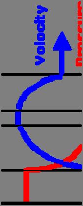
48 Steam Turbine The motive power in a steam turbine is obtained by the rate of change of momentum of a high velocity jet of steam impinging on a curved blade, which is free to rotate. The steam from the boiler is expanded in a nozzle, resulting in the generation of a high velocity jet. This jet of steam impinges on the moving vanes or blades, mounted on a disc / M.S. Ramaiah School of Advanced Studies, Bengaluru 48
49 Steam Turbine Stage A turbine stage consists of stationary stator row (guide vanes or nozzle ring) and rotating rotor row. In the guide vanes, the high pressure, high temperature steam is expanded, resulting li in high hflow velocity. The guide vanes also direct the flow to the rotor blades at an appropriate angle. In the rotor, the flow direction is changed and kinetic energy of the working fluid is absorbed by the rotor shaft producing mechanical energy. Steam Turbine Principle Process of complete expansion of steam takes place in stationary nozzle and the velocity energy is converted into mechanical work on the turbine blades. Pressure drop with expansion and generation of mechanical energy takes place in the moving blades. Pressure drop may be partly effected in nozzles and partly in moving blades which are so designed that expansion of steam takes place in them. High velocity jet from nozzle produces an impulse on the moving blade and the jet coming out at still higher velocity from moving blades produces a M.S. Ramaiah School of Advanced Studies, Bengaluru 49


50 Steam Turbine Types Impulse Turbine Reaction M.S. Ramaiah School of Advanced Studies, Bengaluru 50


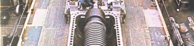
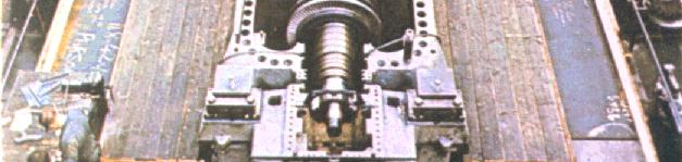
51 Steam Turbine Blades and M.S. Ramaiah School of Advanced Studies, Bengaluru 51
52 Steam Turbine Specification Process industry Power plant Speed 9500 RPM 3000 rpm Power output kw 130 MW Steam inlet temperature 425 ºC 537 ºC Steam inlet pressure 45 bar abs 126 bar abs Condenser Vacuum pressure 0.07 bar abs 0.09 bar abs Steam Rate 100 TPH 415 TPH Exhaust Condensing Condensing No of Extraction 1 5 (3 LP ; 2 HP) Extraction 1 temperature 140 C 420 C / 345 C (HP) Extraction 1 pressure 1.9 bar abs 35 bar abs Extraction 2 mass flow 50.0 TPH 98 TPH Cooling water Temperature 36 C 38 C * The values are M.S. Ramaiah School of Advanced Studies, Bengaluru 52
53 Hydraulic Turbines Types of Hydraulic Turbines Pelton turbine Kaplan turbine Francis M.S. Ramaiah School of Advanced Studies, Bengaluru 53


.")
54 Pelton Turbine The Pl Pelton turbine is a tangential flow impulse turbine. It is most efficient in high head applications. Pelton turbines in power plants operate with net heads ranging from 656 to 4,921 ft (200 to 1,500 M.S. Ramaiah School of Advanced Studies, Bengaluru 54
55 Francis Turbine The Francis turbine is a reaction turbine, which means that the working fluid changes pressure as it moves through the turbine, giving gup its energy. The inlet is spiral shaped. Guide vanes direct the water tangentially to the runner. The radial flow acts on the runner vanes, causing it to spin. The guide vanes (or wicket gates) are adjustable in order to allow efficient turbine operation for a range of water flow conditions. Power plants operate with net heads ranging from 66 to 2,461 ft (20 to 750 M.S. Ramaiah School of Advanced Studies, Bengaluru 55
56 Kaplan Turbine TheKaplan turbine is a propeller-type water turbine that has adjustable blades. It was developed in 1913 by the Austrian professor, Viktor Kaplan. The Kaplan turbine was an evolution of the Francis turbine. Its invention allowed efficient power production in low head applications that was not possible with Francis turbines. Kaplan turbines are now widely used throughout the world in high flow, low head power production. Power plants operate with net heads ranging from 33 to 230 ft (10 to 70 M.S. Ramaiah School of Advanced Studies, Bengaluru 56
57 Hydraulic Turbine Specification Francis + Kaplan # Pelton* Power 47.1 MW 59 MW 18.6 MW Total head 454 m 24.7 m 1748 m Flow coefficient NA- Blade diameter to width ratio NA- Hydraulic losses 20% -NA- Jet velocity -NA- 177 m/s Speed 750 rpm 94.7 rpm 500 rpm Pitch diameter of wheel -NA m Jet diameter -NA_ 94.2 mm # St. Lawrence Power Dam + Fionnay, Switzerland * Dixence, Switzerland Note: The values are M.S. Ramaiah School of Advanced Studies, Bengaluru 57

 A wind turbine is a machine for")


58 Wind Turbines Wind turbines are broadly classified as: Horizontal axis wind turbine (HAWT) Vertical axis wind turbine (VAWT) A wind turbine is a machine for converting the kinetic energy in wind dinto mechanical energy. If the mechanical energy is used directly by machinery, such as a pump or grinding stones, the machine is usually called a windmill. If the mechanical energy is converted to electricity, the machine is called a wind M.S. Ramaiah School of Advanced Studies, Bengaluru 58
59 Components of a Wind Turbine M.S. Ramaiah School of Advanced Studies, Bengaluru 59
60 Wind Turbine Specification GE 1.5 MW VestasV Diameter 100 m 77 m 42 m Speed 18.5 rpm 10.4 to 20.5 rpm (variable) 30 rpm Power output 3 MW 1.5 MW 0.6 MW Airfoil NACA 05 -NA- NACA634XX Axle height 100 m 100 m 40 m Wind velocity 11.8 m/s 12 m/s 16 m/s Operating limits -20 to 40 0 C -20 to 40 0 C -20 to 40 0 C * The values are M.S. Ramaiah School of Advanced Studies, Bengaluru 60

61 Pumps Pump Classification Jet pump Centrifugal pumps Electromagnetic ti pumps Jet pumps Screw pumps Gear pumps Lobe pumps Sliding vane pumps Gear pump Lobe pump Vane M.S. Ramaiah School of Advanced Studies, Bengaluru 61
62 Types of Pumps Axial lflow Pumps single stage or multistage open impeller fixed pitch variable pitch closed impeller RdilFl Radial Flow Pumps single suction or double suction self priming or non priming single stage or multistage open impeller semi open impeller closed impeller Mixed Flow Pumps single suction or double suction self priming i or non priming i single stage or M.S. Ramaiah School of Advanced Studies, Bengaluru 62
63 Types of Pumps ( contd.) Accelerate flow by imparting kinetic energy Decelerate flow (diffuse) in stator Results in increase in fluid pressure Impeller profiles Radial flow Mixed flow Axial M.S. Ramaiah School of Advanced Studies, Bengaluru 63
64 Axial Flow Pumps An axial flow pump essentially consists of a propeller in a tube. The propeller can be driven directly by a sealed motor in the tube or by a right-angle drive shaft that pierces the tube. The main advantage of an AFP is that it can easily be adjusted to run at peak efficiency at low-flow/high-pressure and high-flow/low-pressure by changing the pitch of the propeller. Application of axial flow pump Evaporators and crystallizers Waste-water handling Sludge transfer Flood control Flume recirculation Irrigation Regeneration Heat recovery High-volume M.S. Ramaiah School of Advanced Studies, Bengaluru 64
65 Centrifugal Pumps Centrifugal means directing or moving away from the axis. Centrifugal pumps use an impeller and a volute to create partial vacuum and discharge pressure necessary to move water through the casing. Radial flow and mixed flow pumps are commonly referred to as centrifugal pumps. The rotating element of a centrifugal pump is called impeller. An open impeller consists of a hub to which vanes are attached, while a closed impeller has plates or shrouds on each side of the vanes. The open impeller is less efficient compared to closed one but suited to handle liquids containing solids. Radial pumps are provided with a spiral casing, often referred as a volute casing, which guides the flow from the impeller to the discharge pipe. A gradually increasing cross section around the casing tends to maintain a constant flow velocity within the casing. Some pumps have diffuser vanes between impeller exit and volute casing. Some pumps are of the double suction type. Higher the pressure drop or head, lower is the flow M.S. Ramaiah School of Advanced Studies, Bengaluru 65


66 Centrifugal Pumps Closed or shrouded impeller Semi open M.S. Ramaiah School of Advanced Studies, Bengaluru 66
67 Mixed Flow Pumps Mixed flow pumps are in-line pumps, used for applications requiring high volume flow with a low discharge pressure. One application that has used this technology in recent years, is high-performance jet-ski propulsion, where the pumps are used to power the water crafts with an outgoing stream of high speed M.S. Ramaiah School of Advanced Studies, Bengaluru 67
68 Pump Specification Booster pump Condensate extraction pump Suction pressure 5.59 bar 0.09 bar abs Volume flow rate 250 m 3 /h 160m 3 h Discharge pressure 9.16 bar 2.6 bar abs Power input 36.3 kw 46.5 kw Speed 6000 rpm 4800 rpm NPSH 22 m -NA- Efficiency 81% -NA- Fluid handled Boiler feed pump Condensate Specific gravity of fluid NA- Temperature of fluid 426 K 315 K * The values are M.S. Ramaiah School of Advanced Studies, Bengaluru 68
69 Turbomachinery Design Procedure Market Research Specification Customer Requirements Modifications in Aerodynamics Component Test Rigs: Compressor, Combustor, Turbine, etc. Uprated and Modified Versions Design Modifications Preliminary Studies: Choice of Cycle; Type of Turbomachinery; Layout Thermodynamic Design Point Studies Aerodynamics of Compressor, Turbine, Intake, Exhaust, etc. Mechanical Design: Stressing of Discs, Blades, Casing; Vibration, Whirling, Bearings Detail Design and Manufacture Test and Development Modifications in Stressing Off-design Performance Control lsystem Studies Production After-sales M.S. Ramaiah School of Advanced Studies, Bengaluru 69
70 Session Summary Turbomachinery has been defined. Classification of turbomachinery has been dealt with. Various turbomachinery components have been explained. Applications of different turbomachinery have been explained. Typical specifications for various turbomachinery have been discussed. Basic design concepts have been M.S. Ramaiah School of Advanced Studies, Bengaluru 70
PEMP RMD M.S.Ramaiah School of Advanced Studies
 Introduction to Turbomachines Session delivered by: Prof. Q.H. Nagpurwala 1 Session Objectives This session is intended to introduce the following: Turbomachinery and their application Types of turbomachines
T.E. (Mech., Mech. S/W) (Semester II) Examination, 2011 TURBOMACHINES (New) (2008 Pattern)
 (Semester II) Examination, 2011 TURBOMACHINES (New) (2008 Pattern)") *4063218* [4063] 218 T.E. (Mech., Mech. S/W) (Semester II) Examination, 2011 TURBOMACHINES (New) (2008 Pattern) Time : 3 Hours Marks : 100 Instructions : 1) Answer any three questions from each Section.
*4063218* [4063] 218 T.E. (Mech., Mech. S/W) (Semester II) Examination, 2011 TURBOMACHINES (New) (2008 Pattern) Time : 3 Hours Marks : 100 Instructions : 1) Answer any three questions from each Section.
Turbo Machines Pumps and Turbines ME 268
 Turbo Machines Pumps and Turbines ME 268 Turbo Machines Turbo machines are dynamic fluid machines that either extract energy from a fluid (turbine) or add energy to a fluid (pump) as a result of dynamic
Alpha College of Engineering
 Alpha College of Engineering Department of Mechanical Engineering TURBO MACHINE (10ME56) QUESTION BANK PART-A UNIT-1 1. Define a turbomahcine. Write a schematic diagram showing principal parts of a turbo
[4163] T.E. (Mechanical) TURBO MACHINES (2008 Pattern) (Common to Mech. S/W) (Sem. - II)
![[4163] T.E. (Mechanical) TURBO MACHINES (2008 Pattern) (Common to Mech. S/W) (Sem. - II)](/thumbs/77/76045894.jpg "[4163] T.E. (Mechanical) TURBO MACHINES (2008 Pattern) (Common to Mech. S/W) (Sem. - II)") Total No. of Questions : 12] P1061 SEAT No. : [Total No. of Pages : 7 [4163] - 218 T.E. (Mechanical) TURBO MACHINES (2008 Pattern) (Common to Mech. S/W) (Sem. - II) Time : 3 Hours] [Max. Marks :100 Instructions
Total No. of Questions : 12] P1061 SEAT No. : [Total No. of Pages : 7 [4163] - 218 T.E. (Mechanical) TURBO MACHINES (2008 Pattern) (Common to Mech. S/W) (Sem. - II) Time : 3 Hours] [Max. Marks :100 Instructions
SHRI RAMSWAROOP MEMORIAL COLLEGE OF ENGG. & MANAGEMENT
 B.Tech. [SEM VI(ME-61,62,63 & 64)] QUIZ TEST-1 Q-1). A jet strikes a smooth curved vane moving in the same direction as the jet and the jet get reversed in the direction. Show that the maximum efficiency
Principles of. Turbomachinery. Seppo A. Korpela. The Ohio State University WILEY A JOHN WILEY & SONS, INC., PUBLICATION
 Principles of Turbomachinery Seppo A. Korpela The Ohio State University WILEY A JOHN WILEY & SONS, INC., PUBLICATION CONTENTS Foreword xiii Acknowledgments xv 1 Introduction 1 1.1 Energy and fluid machines
Chapter 5 1. Hydraulic Pumps (pp , Gorla & Khan; Wiki)
") Chapter 5 1. Hydraulic Pumps (pp. 47 90, Gorla & Khan; Wiki) 1. Two Basic Categories of Pumps Positive Displacement (PD) Pumps A positive displacement pump causes a fluid to move by trapping a fixed amount
Chapter 5 1. Hydraulic Pumps (pp. 47 90, Gorla & Khan; Wiki) 1. Two Basic Categories of Pumps Positive Displacement (PD) Pumps A positive displacement pump causes a fluid to move by trapping a fixed amount
UNIT I: UNIFORM FLOW PART B
 UNIT I: UNIFORM FLOW PART-A 1 Define open channel flow with example BT-1-1 2 Distinguish between open channel flow and pipe flow. BT-4-1 3 Compute the hydraulic mean depth of a small channel 1m wide, 0.5m
Code No: R Set No. 1
 Code No: R05310302 Set No. 1 III B.Tech I Semester Regular Examinations, November 2008 HYDRAULIC MACHINERY AND SYSTEMS ( Common to Mechanical Engineering and Automobile Engineering) Time: 3 hours Max Marks:
Pumps, Turbines, and Pipe Networks, part 2. Ch 11 Young
 Pumps, Turbines, and Pipe Networks, part 2 Ch 11 Young Pump and Turbine Dimensional Analysis (11.5 Young) Say we want to replace turbines on the Hoover Dam Want to have a good design Essentially impossible
(a) the inlet and exit vane angles, (b) work done (c) Efficiency of the system. [16]
![(a) the inlet and exit vane angles, (b) work done (c) Efficiency of the system. [16]](/thumbs/81/82633878.jpg "(a) the inlet and exit vane angles, (b) work done (c) Efficiency of the system. [16]") Code No: R05310302 Set No. 1 III B.Tech I Semester Regular Examinations, November 2007 HYDRAULIC MACHINERY AND SYSTEMS ( Common to Mechanical Engineering and Automobile Engineering) Time: 3 hours Max Marks:
Code No: R05310302 Set No. 1 III B.Tech I Semester Regular Examinations, November 2007 HYDRAULIC MACHINERY AND SYSTEMS ( Common to Mechanical Engineering and Automobile Engineering) Time: 3 hours Max Marks:
CH 6.docx CH 1.docx CH 2.docx CH 3.docx CH 4.docx CH 5.docx
 CH 6.docx CH 1.docx CH 2.docx CH 3.docx CH 4.docx CH 5.docx CH 6 MISCELLANEOUS MACHINES THEORY (1) With neat sketch explain construction and working of hydraulic torque Convertor [643] (2) Write short
 DEPARTMENT OF CIVIL ENGINEERING CE6403/ APPLIED HYDRAULIC ENGINEERING QUESTION BANK TWO MARKS UNIT I UNIFORM FLOW 1. Differentiate open channel flow from pipe flow. 2. What is specific energy and is the
2. (a) How do you classify water turbines? (b) Define and explain different efficiencies of a water turbine. [8+8]
![2. (a) How do you classify water turbines? (b) Define and explain different efficiencies of a water turbine. [8+8]](/thumbs/83/87300886.jpg "2. (a) How do you classify water turbines? (b) Define and explain different efficiencies of a water turbine. [8+8]") Code No: RR310302 Set No. 1 III B.Tech I Semester Supplementary Examinations, February 2007 HYDRAULIC MACHINERY AND SYSTEMS ( Common to Mechanical Engineering and Automobile Engineering) Time: 3 hours
Code No: RR310302 Set No. 1 III B.Tech I Semester Supplementary Examinations, February 2007 HYDRAULIC MACHINERY AND SYSTEMS ( Common to Mechanical Engineering and Automobile Engineering) Time: 3 hours
Hydraulic Machines, K. Subramanya
 Hydraulic Machines power point presentation Slides has been adapted from Hydraulic Machines, K. Subramanya 2016-2017 Prepared by Dr. Assim Al-Daraje 1 Chapter (1 Part 1) Prepared by Dr. Assim Al-Daraje
SUMMER 15 EXAMINATION
 SUMMER 15 EXAMINATION Subject Code: 17413 ( EME ) Model Answer Important Instructions to examiners: 1) The answers should be examined by key words and not as word-to-word as given in the model answer scheme.
Evaluating Performance of Steam Turbine using CFD
 Evaluating Performance of Steam Turbine using CFD Sivakumar Pennaturu Department of Mechanical Engineering KL University, Vaddeswaram, Guntur,AP, India Dr P Issac prasad Department of Mechanical Engineering
R13. (12M) efficiency.
 efficiency.") SET - 1 II B. Tech I Semester Regular/Supplementary Examinations, Oct/Nov - 2016 THERMAL AND HYDRO PRIME MOVERS (Electrical and Electronics Engineering) Time: 3 hours Max. Marks: 70 Note: 1. Question Paper
SET - 1 II B. Tech I Semester Regular/Supplementary Examinations, Oct/Nov - 2016 THERMAL AND HYDRO PRIME MOVERS (Electrical and Electronics Engineering) Time: 3 hours Max. Marks: 70 Note: 1. Question Paper
3. Compressor. Gas Turbines for Power Plants 3. Compressor 1 / 136
 3. Compressor Gas Turbines for Power Plants 3. Compressor 1 / 136 Contents 1 3 4 5 6 7 8 9 10 Basic Principles of an Axial Compressor Compressor Thermodynamics and Fluid Dynamics 18 Dimensionless Numbers
2. In terms of operating as a machine, a sail boat energy from the air. A. Extracts B. Adds
 CHAPTER 12 1.Turbomachines are mechanical devices that either energy from a fluid, in the case of a turbine, or energy to a fluid, in the case of a pump. YOUR ANSWER: Extract, add 2. In terms of operating
Download From:
 Fluid Mechanics 1. A single acting reciprocating pump, running at 60 r.p.m, delivers 0.01 m2/sec of water. The area of the piston is0.05m2 and stroke length is 40 cm. Then theoretical discharge of the
Code No: R Set No. 1
 Code No: R050210201 Set No. 1 II B.Tech I Semester Regular Examinations, November 2006 FLUID MECHANICS & HYDRAULIC MACHINERY (Electrical & Electronic Engineering) Time: 3 hours Max Marks: 80 Answer any
00046 Term-End Examination June, 2015
 No. of Printed Pages : 5 BIME-013 B.Tech. - VIEP - MECHANICAL ENGINEERING (BTMEVI) 00046 Term-End Examination June, 2015 BIME-013 : TURBO MACHINES Time : 3 hours Maximum Marks : 70 Note : Answer any five
R13 SET - 1 '' ''' '' ' '''' Code No: RT31035
 R13 SET - 1 III B. Tech I Semester Regular/Supplementary Examinations, October/November - 2016 THERMAL ENGINEERING II (Mechanical Engineering) Time: 3 hours Max. Marks: 70 Note: 1. Question Paper consists
RRB TECHNICAL EXAM QUESTIONS
 RRB TECHNICAL EXAM QUESTIONS Fluid Mechanics 1. A single acting reciprocating pump, running at 60 r.p.m, delivers 0.01 m2/sec of water. The area of the piston is0.05m2 and stroke length is 40 cm. Then
Design and Fatigue Analysis of Turbine Rotor Blade by Using F.E.M
 Design and Fatigue Analysis of Turbine Rotor Blade by Using F.E.M Murali. K M.Tech Student, (Machine Design), Mechanical Engineering Department, Sarada Institute of Science Technology and management. ABSTRACT:
semester + ME6404 THERMAL ENGINEERING UNIT III NOZZLES, TURBINES & STEAM POWER CYCLES UNIT-III
 ME6404 THERMAL ENGINEERING UNIT III NOZZLES, TURBINES & STEAM POWER CYCLES UNIT-III 3. 1 CONTENTS 3.1 Flow of steam through nozzles: 3.2 Continuity and steady flow energy equations 3.3 Types of Nozzles
UNIT 5 HYDRAULIC MACHINES. Lecture-01
 1 UNIT 5 HYDRAULIC MACHINES Lecture-01 Turbines Hydraulic machines which convert hydraulic energy into mechanical energy. This mechanical energy is used to run electric generator which is directly coupled
Code No: RR Set No. 1
 Code No: RR310303 Set No. 1 III B.Tech I Semester Regular Examinations, November 2006 THERMAL ENGINEERING-II (Mechanical Engineering) Time: 3 hours Max Marks: 80 Answer any FIVE Questions All Questions
PEMP RMD & Cycle Performance. M.S.Ramaiah School of Advanced Studies
 Steam Se Turbine ub ecyces Cycles & Cycle Performance Session delivered by: Prof. Q.H. Nagpurwala 1 Session Objectives This session is intended to discuss the following: Basic construction and classification
 VALLIAMMAI ENGINEERING COLLEGE DEPARTMENT OF MECHANICAL ENGINEERING CE6451-FLUID MECHANICS AND MACHINERY UNIT- I: FLUID PROPERTIES AND FLOW CHARACTERISTICS PART-A 1. Find the surface tension in a soap
Code No: R31034 R10 Set No: 1
 Code No: R31034 R10 Set No: 1 JNT University Kakinada III B.Tech. I Semester Regular/Supplementary Examinations, Dec - 2014/Jan -2015 THERMAL ENGINEERING-II (Com. to Mechanical Engineering and Automobile
DESIGN OF A PELTON WHEEL TURBINE FOR A MICRO HYDRO POWER PLANT
 DESIGN OF A PELTON WHEEL TURBINE FOR A MICRO HYDRO POWER PLANT Manjunatha N 1, Kuldeepak Kumar 2, Dr. Thammaih Gowda 3 1, 2 Assistant Professor, Dept. of Mechanical Engineering, N.D.R.K.I.T, Hassan, Karnataka
Introduction to the mechanical design of aircraft engines
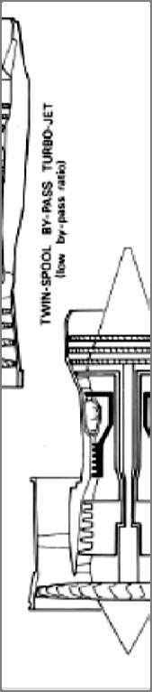
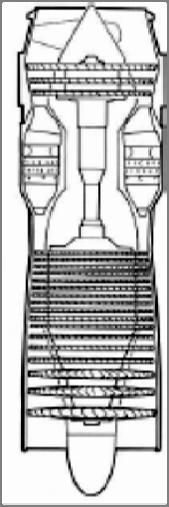
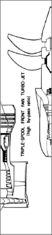
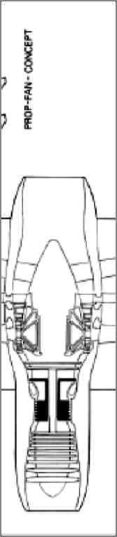
 Introduction to the mechanical design of aircraft engines Reference : AERO0015-1 - MECHANICAL DESIGN OF TURBOMACHINERY - 5 ECTS - J.-C. GOLINVAL 2 Principles of jet propulsion Comparison between the working
SHREE RAMCHANDRA EDUCATION SOCIETY S LONIKAND, PUNE DEPARTMENT OF MECHANICAL ENGINEERING LAB MANUAL
 SHREE RAMCHANDRA EDUCATION SOCIETY S SHREE RAMCHANDRA COLLEGE OF ENGINEERING, LONIKAND, PUNE 412 216 DEPARTMENT OF MECHANICAL ENGINEERING LAB MANUAL TURBO MACHINES(TM) TE (ME) Semester-VI Prepared by Prof.
INCOMPRESSIBLE FLOW TURBOMACHINES Design, Selection, Applications,
 INCOMPRESSIBLE FLOW TURBOMACHINES Design, Selection, Applications, George F. Round Professor Emeritus McMaster University Hamilton, Ontario Canada ELSEVIER BUTTERWORTH HEINEMANN Amsterdam Boston Heidelberg
Experimental Analysis of Flow through Rotating Swirler with Effect of Guide Vane
 Experimental Analysis of Flow through Rotating Swirler with Effect of Guide Vane Mansha kumari 1, Shah Jagruti 2, Arvind.S.Mohite 3 M.E. (JPGTP)Student, Department of mechanical engineering, Faculty of
Design and Simulation of Very Low Head Axial Hydraulic Turbine with Variation of Swirl Velocity Criterion
 International Journal of Fluid Machinery and Systems DOI: http://dx.doi.org/10.5293/ijfms.2014.7.2.068 Vol. 7, No. 2, April-June 2014 ISSN (Online): 1882-9554 Original Paper (Invited) Design and Simulation
Applied Thermodynamics - II
 Gas Turbines Sudheer Siddapureddy sudheer@iitp.ac.in Department of Mechanical Engineering Introduction Jet propulsion is produced, wholly (turbojet) or partially (turboprop), as a result of expansion of
S.Y. Diploma : Sem. III [PG/PT/ME] Thermal Engineering
![S.Y. Diploma : Sem. III [PG/PT/ME] Thermal Engineering](/thumbs/95/122495961.jpg "S.Y. Diploma : Sem. III [PG/PT/ME] Thermal Engineering") S.Y. Diploma : Sem. III [PG/PT/ME] Thermal Engineering Time: 3 Hrs. Prelim Question Paper Solution [Marks : 70 Q.1 Attempt any FIVE of the following. [10] Q.1(a) Explain difference between Thermodynamic
S.Y. Diploma : Sem. III [PG/PT/ME] Thermal Engineering Time: 3 Hrs. Prelim Question Paper Solution [Marks : 70 Q.1 Attempt any FIVE of the following. [10] Q.1(a) Explain difference between Thermodynamic
PAPER-I (Conventional)
") 1. a. PAPER-I (Conventional) 10 kg of pure ice at 10 ºC is separated from 6 kg of pure water at +10 O C in an adiabatic chamber using a thin adiabatic membrane. Upon rupture of the membrane, ice and water
1. a. PAPER-I (Conventional) 10 kg of pure ice at 10 ºC is separated from 6 kg of pure water at +10 O C in an adiabatic chamber using a thin adiabatic membrane. Upon rupture of the membrane, ice and water
Experiment No.2 STUDY & TRIAL ON A FRANCIS TURBINE & PLOTTING OF MAIN /OPERATING CHARACTERISTICS.
 Experiment No.2 STUDY & TRIAL ON A FRANCIS TURBINE & PLOTTING OF MAIN /OPERATING CHARACTERISTICS. Name of the student: Roll No: Date of Performance : Date of Submission Marks Scored: Signature of Staff
CE2253 APPLIED HYDRAULIC ENGINEERING (FOR IV - SEMESTER)
") CE2253 APPLIED HYDRAULIC ENGINEERING (FOR IV - SEMESTER) UNIT I to V QUESTION BANK Prepared by, M.SUGANYA. B.E., LECTURER / CIVIL DEPARTMENT OF CIVIL ENGINEERING CE2253 APPLIED HYDRAULIC ENGINEERING UNIT
CE2253 APPLIED HYDRAULIC ENGINEERING (FOR IV - SEMESTER) UNIT I to V QUESTION BANK Prepared by, M.SUGANYA. B.E., LECTURER / CIVIL DEPARTMENT OF CIVIL ENGINEERING CE2253 APPLIED HYDRAULIC ENGINEERING UNIT
"Leveraging Cross-Industry Know-How for Thermodynamic Cycles & Turbomachinery Component Innovation"
 "Leveraging Cross-Industry Know-How for Thermodynamic Cycles & Turbomachinery Component Innovation" Wednesday, June 17, 2015 Stage Presentation ASME TURBOEXPO 2015 1 About SoftInWay Founded in 1999, we
Renewable and Alternative Energies
 Department of Electrical and Energy Engineering This work is published under a license: Creative Commons BY-NC-SA 4.0 Contents Topic 1. Wind energy. Topic 2. Solar energy. Topic 3. Ocean energy.. Topic
LABORATORY MANUAL FLUID MACHINE ME- 315-F
 LABORATORY MANUAL FLUID MACHINE ME- 315-F LIST OF THE EXPERIMENTS SNO NAME OF THE EXPERIMENTS 1 To study the constructional details of a pelton turbine and draw its fluid flow circuit. 2 To study the constructional
Thermodynamics of. Turbomachinery. Fluid Mechanics and. Sixth Edition. S. L. Dixon, B. Eng., Ph.D. University of Liverpool, C. A. Hall, Ph.D.
 Fluid Mechanics and Thermodynamics of Turbomachinery Sixth Edition S. L. Dixon, B. Eng., Ph.D. Honorary Senior Fellow, Department of Engineering, University of Liverpool, UK C. A. Hall, Ph.D. University
Thermo-fluid Dynamics, Design and Performance
 Unit T24: Aircraft Gas Turbine Thermo-fluid Dynamics, Design and Performance Unit code: K/504/0205 QCF level: 6 Credit value: 15 Aim The aim of this unit is to give learners an understanding of the fluid
(Refer Slide Time: 6: 22)
") Fluid Machines. Professor Sankar Kumar Som. Department Of Mechanical Engineering. Indian Institute Of Technology Kharagpur. Lecture-17. Governing of Reaction Turbine. Good morning and welcome you all to
Fluid Machines. Professor Sankar Kumar Som. Department Of Mechanical Engineering. Indian Institute Of Technology Kharagpur. Lecture-17. Governing of Reaction Turbine. Good morning and welcome you all to
ANALYSIS OF COOLING TECHNIQUES OF A GAS TURBINE BLADE
 ANALYSIS OF COOLING TECHNIQUES OF A GAS TURBINE BLADE G. Anil Kumar 1, Dr. I.N. Niranjan Kumar 2, Dr. V. Nagabhushana Rao 3 1 M.Tech Marine Engineering and Mechanical Handling, Andhra University College
INSTITUTE OF AERONAUTICAL ENGINEERING (Autonomous) Dundigal, Hyderabad
 Dundigal, Hyderabad") INSTITUTE OF AERONAUTICAL ENGINEERING (Autonomous) Dundigal, Hyderabad -500 043 MECHANICAL ENGINEERING ASSIGNMENT Course Name : THERMAL ENGINEERING II Course Code : A50518 Class : III B. Tech I Semester
INSTITUTE OF AERONAUTICAL ENGINEERING (Autonomous) Dundigal, Hyderabad -500 043 MECHANICAL ENGINEERING ASSIGNMENT Course Name : THERMAL ENGINEERING II Course Code : A50518 Class : III B. Tech I Semester
Turbomachinery Aerodynamics
 Lect- 1 1 Turbomachinery Aerodynamics A Video course by Bhaskar Roy A M Pradeep Aerospace Engineering Department I.I.T., Bombay 2 Course Outline Introduction to Turbomachineries: Axial flow compressors
THERMAL AND HYDRAULIC MACHINES UNIT 2
 THERMAL AND HYDRAULIC MACHINES UNIT 2 A steam turbine is a device that extracts thermal energy from pressurized steam and uses it to do mechanical work on a rotating output shaft. Its modern manifestation
Chapter 5 1. Hydraulic Turbines (Gorla & Khan, pp )
") Electronic Notes Chapter 5 1. Hydraulic Turbines (Gorla & Khan, pp.91 141) 1. Terminologies Related to A Hydropower Plant Hoover Dam generates more than 4 billion kilowatt-hours of electricity each year,
Electronic Notes Chapter 5 1. Hydraulic Turbines (Gorla & Khan, pp.91 141) 1. Terminologies Related to A Hydropower Plant Hoover Dam generates more than 4 billion kilowatt-hours of electricity each year,
Unit No.4-1 Higashi Niigata Thermal Power Station Operating Status O C Class Gas Turbine Operation -
 101 Unit No.4-1 Higashi Niigata Thermal Power Station Operating Status - 1450 O C Class Gas Turbine Operation - Yoshiaki Tsukuda *1 Eiji Akita *1 Yoichi Iwasaki *1 Koichiro Yanou *1 Yutaka Kawata *2 Toshihide
CHAPTER 5 MASS AND ENERGY ANALYSIS OF CONTROL VOLUMES
 Thermodynamics: An Engineering Approach 8th Edition in SI Units Yunus A. Ç engel, Michael A. Boles McGraw-Hill, 2015 CHAPTER 5 MASS AND ENERGY ANALYSIS OF CONTROL VOLUMES Objectives Develop the conservation
Tutorial letter 101/0/2016
 Tutorial letter 101/0/2016 Hydraulic Machines III (Theory) FMA3602 Year Module Department of Mechanical and Industrial Engineering IMPORTANT INFORMATION: This tutorial letter contains important information
Ten glorious years of service to industry & customers ENGINEERING SERVICE OVER VIEW & IMPORTANT PROJECT- CASE STUDY
 ENGINEERING SERVICE OVER VIEW & IMPORTANT PROJECT- CASE STUDY STRESS ANALYSIS Structural Strength of Turbine Casing Client : Hydro Power sector Scope of work: To analyse the given structure to bear the
SCHOOL OF COMPUTING, ENGINEERING AND MATHEMATICS SEMESTER 1 EXAMINATIONS 2014/2015 ME257. Fluid Dynamics. Answer FOUR out of SIX questions
 s SCHOOL OF COMPUTING, ENGINEERING AND MATHEMATICS SEMESTER 1 EXAMINATIONS 2014/2015 ME257 Fluid Dynamics Time allowed: TWO hours Answer: Answer FOUR out of SIX questions Items permitted: Any approved
ASSIGNMENT 2 Coal and Ash Handling System and Draught Systems
 ASSIGNMENT 1 Thermal Power Plant & High Pressure Boiler 1. State the factors to be considered for selection of site for thermal power plant 2. State desirable to control the super heat temperature. Explain
Theoretical Analysis of Horizontal Axis Wind Turbine for Low Wind Velocity
 Available online at www.ijiere.com International Journal of Innovative and Emerging Research in Engineering e-issn: 2394-3343 p-issn: 2394-5494 Theoretical Analysis of Horizontal Axis Wind Turbine for
Turbo machinery Aerodynamics Prof: Bhaskar Roy Prof. A M Pradeep Department of Aerospace Engineering Indian Institute of Technology, Bombay
 Turbo machinery Aerodynamics Prof: Bhaskar Roy Prof. A M Pradeep Department of Aerospace Engineering Indian Institute of Technology, Bombay Lecture No. # 29 Turbine Blade Design: Turbine Profiles, Airfoil
PESIT Bangalore South Campus Hosur road, 1km before Electronic City, Bengaluru -100 Department of Basic Science and Humanities
 USN 1 P E PESIT Bangalore South Campus Hosur road, 1km before Electronic City, Bengaluru -100 Department of Basic Science and Humanities INTERNAL ASSESSMENT TEST 1 Date : 28/08/2017 Marks: 40 Subject &
UNIT I FLUID PROPERTIES AND FLUID STATICS
 SIDDHARTH GROUP OF INSTITUTIONS :: PUTTUR Siddharth Nagar, Narayanavanam Road 517583 QUESTION BANK (DESCRIPTIVE) Subject with Code : FM & HM (16CE112) Year & Sem: II-B.Tech & I-Sem Course & Branch: B.Tech
Power Recovery in LNG Regasification Plants
 Power Recovery in LNG Regasification Plants Harry K. Clever Director of Sales hclever@ebaraintl.com Hans E. Kimmel Executive Director R&D hkimmel@ebaraintl.com Ebara International Corporation Sparks, Nevada,
= Guide angle = angle between direction of jet and direction of motion of vane/bucket.
 GEC223: FLUID MECHANICS MODULE 4: HYDROPOWER SYSTEMS TOPIC: IMPULSE TURBINES-PELTON WHEEL DEPARTMENT OF CIVIL ENGINEERING, LANDMARK UNIVERSITY, KWARA STATE, NIGERIA CONSTRUCTION AND WORKING OF A PELTON
Thermodynamic Considerations for Large Steam Turbine Upgrades and Retrofits
 POWER-GEN Asia 2011 Kuala-Lumpur, Malaysia September 27-29, 2011 Thermodynamic Considerations for Large Steam Turbine Upgrades and Retrofits Leonid Moroz, Kirill Grebennik 15 New England Executive Park,
University Curriculum Development for Decentralized Wastewater Management
 Page i University Curriculum Development for Decentralized Wastewater Management Module Text Paul Trotta, P.E., Ph.D. Justin Ramsey, P.E. Chad Cooper September 004 Page ii NDWRCDP Disclaimer This work
Department Mechanical Engineering. Lab Manual. Fluid Machinery Lab. B.Tech-VI Semester KCT COLLEGE OF ENGG. & TECH. VILLAGE FATEHGARH DISTT.
 Department Mechanical Engineering Lab Manual B.Tech-VI Semester KCT COLLEGE OF ENGG. & TECH. VILLAGE FATEHGARH DISTT.SANGRUR KCT College of Engineering & Technology Department-ME EXPERIMENTS 1. Conducting
Compact liquefied gas expander technological advances
 Compact liquefied gas expander technological advances Joel V. Madison President Ebara International Corporation SYNOPSIS LNG expanders are now an important part of every new LNG liquefaction plant. The
Experience and Examples of Optimization of Axial Turbines Flow Paths
 7 Experience and Examples of Optimization of Axial Turbines Flow Paths In this chapter, as an example of practical use of the developed theory of optimal design of axial turbines flow paths, the results
NPTEL
 NPTEL Syllabus Turbomachinery Aerodynamics - Video course COURSE OUTLINE to Turbomachineries Axial flow compressors and Fans: ; Aero-Thermodynamics of flow through an Axial flow Compressor stage; Losses
Appendix B. Glossary of Steam Turbine Terms
 Operator s Guide to General Purpose Steam Turbines: An Overview of Operating Principles, Construction, Best Practices, and Troubleshooting. Robert X. Perez and David W. Lawhon. 2016 Scrivener Publishing
MECHANICAL ENGINEERING DEPARTMENT, OITM
 Sem.:4 th Subject: Energy Conversion Paper: ME-201E UNIT-1 Q1. Explain the seismometer with its working principle. (Important Question) (20) Q2. Classify the fuels and define calorific value of fuels.
Design Details of a 600 MW Graz Cycle Thermal Power Plant for CO 2
 Institute for Thermal Turbomaschinery and Machine Dynamics Graz University of Technology Erzherzog-Johann-University Design Details of a 600 MW Graz Cycle Thermal Power Plant for CO 2 Capture Presentation
AC : THE ENERGY SYSTEMS LABORATORY AT KETTERING UNIVERSITY
 AC 2007-27: THE ENERGY SYSTEMS LABORATORY AT KETTERING UNIVERSITY Ahmad Pourmovahed, Kettering University Ahmad Pourmovahed is a Professor of Mechanical Engineering at Kettering University. He received
Aerodynamic Analysis of Horizontal Axis Wind Turbine Using Blade Element Momentum Theory for Low Wind Speed Conditions
 Aerodynamic Analysis of Horizontal Axis Wind Turbine Using Blade Element Momentum Theory for Low Wind Speed Conditions Esam Abubaker Efkirn, a,b,* Tholudin Mat Lazim, a W. Z. Wan Omar, a N. A. R. Nik Mohd,
Contents. Part I Design: Theory and Practice 1
 Contents Preface to the Fourth Edition Preface to the Third Edition Preface to the Second Edition Preface to the First Edition Foreword to the First Edition About the Author xix xxiii xxvii xxix xxxi xxxiii
Applied Thermodynamics - II
 Gas Turbines - Sudheer Siddapureddy sudheer@iitp.ac.in Department of Mechanical Engineering Auxiliary Devices Other components/arrangements Intercoolers between the compressors Reheat combustion chambers
CFD Analysis of recirculating flows induced by Axial Swirler
 CFD Analysis of recirculating flows induced by Axial Swirler P.Muthukumar 1, S.R.Balakrishnan 2 PG scholar 1, Director/H.O.D 2 1, 2, Department of Aeronautical Engineering, Nehru institute of engineering
National Maritime Center
 National Maritime Center Providing Credentials to Mariners U.S.C.G. Merchant Marine Exam (Sample Examination) Page 1 of 23 Choose the best answer to the following Multiple Choice Questions. 1. Newton's
EXPERIMENTAL INVESTIGATION OF DOWNSTREAM FLOW FIELD IN A LINEAR TURBINE CASCADE: EFFECTS OF RELATIVE WALL MOTION
 EXPERIMENTAL INVESTIGATION OF DOWNSTREAM FLOW FIELD IN A LINEAR TURBINE CASCADE: EFFECTS OF RELATIVE WALL MOTION V. Uma Maheshwar, Associate Professor, Dept of Mechanical Engineering, University College
PERFORMANCE ANALYSIS OF A STEAM POWER PLANT OPERATING UNDER SUPERHEATED AND ISENTROPIC CONDITIONS
 Equatorial Journal of Engineering (2018) 22-28 Journal Homepage: www.erjournals.com ISSN: 0184-7937 PERFORMANCE ANALYSIS OF A STEAM POWER PLANT OPERATING UNDER SUPERHEATED AND ISENTROPIC CONDITIONS Kingsley
MODELING AND CFD ANALYSIS OF A MINIATURE RADIAL TURBINE FOR DISTRIBUTED POWER GENERATION SYSTEMS
 SusTEM Special Sessions on Thermal Energy Management MODELING AND CFD ANALYSIS OF A MINIATURE RADIAL TURBINE FOR DISTRIBUTED POWER GENERATION SYSTEMS Kiyarash Rahbar, Saad Mahmoud, Raya K. Al-Dadah, Ahmed
Large Eddy Simulation of temperature distribution in an aero engine annular combustor with a swirler and Nanoparticle injection
 Large Eddy Simulation of temperature distribution in an aero engine annular combustor with a swirler and Nanoparticle injection 1 Vishnu Sasidharan, 2 Arun Kumar A.R Assistant professor Department of Aeronautical
Course 0101 Combined Cycle Power Plant Fundamentals
 Course 0101 Combined Cycle Power Plant Fundamentals Fossil Training 0101 CC Power Plant Fundamentals All rights reserved. No part of this publication may be reproduced, distributed, or transmitted in any
CE6403 APPLIED HYDRAULIC ENGINEERING UNIT 1 UNIFORM FLOW
 CE6403 APPLIED HYDRAULIC ENGINEERING UNIT 1 UNIFORM FLOW Definition and differences between pipe flow and open channel flow - Types of Flow - Properties of open channel - Fundamental equations - Velocity
3. Design of Generation Equipment. 3.1 Turbine (1) Turbine Types Turbines are classified into two types according to their water energy utility:
 Turbine Types Turbines are classified into two types according to their water energy utility:") 3. Design of Generation Equipment 3.1 Turbine (1) Turbine Types Turbines are classified into two types according to their water energy utility: Impulse Turbines: all available water energy is converted
3. Design of Generation Equipment 3.1 Turbine (1) Turbine Types Turbines are classified into two types according to their water energy utility: Impulse Turbines: all available water energy is converted
FINAL Examination Paper (COVER PAGE) Programme : Diploma in Mechanical Engineering. Time : 8.00 am am Reading Time : 10 Minutes
 Programme : Diploma in Mechanical Engineering. Time : 8.00 am am Reading Time : 10 Minutes") Session : May 2013 FINAL Examination Paper (COVER PAGE) Programme : Diploma in Mechanical Engineering Course : EGR2180 : FLUIDS MECHANICS 2 Date of Examination : July 25, 2013 Time : 8.00 am 10.10 am Reading
Session : May 2013 FINAL Examination Paper (COVER PAGE) Programme : Diploma in Mechanical Engineering Course : EGR2180 : FLUIDS MECHANICS 2 Date of Examination : July 25, 2013 Time : 8.00 am 10.10 am Reading
SCHOOL OF COMPUTING, ENGINEERING AND MATHEMATICS SEMESTER 1 EXAMINATIONS 2015/2016 ME257. Fluid Dynamics
 s SCHOOL OF COMPUTING, ENGINEERING AND MATHEMATICS SEMESTER 1 EXAMINATIONS 2015/2016 ME257 Fluid Dynamics Time allowed: TWO hours Answer: Answer TWO from THREE questions in section A and TWO from THREE
High Bridge Combined Cycle Plant
 High Bridge Combined Cycle Plant Location: Down town St. Paul, on the Mississippi River Plant Description: High Bridge is a combined cycle generating facility. A combined cycle plant produces electricity
Chapter (2) Prepared by Dr. Assim Al-Daraje
 Prepared by Dr. Assim Al-Daraje") Chapter (2) Prepared by Dr. Assim Al-Daraje 1 INTRODUCTION The Pelton turbine is ideal for high-head and low-discharge situations. The number of jets in a turbine is usually one. However, where additional
Chapter (2) Prepared by Dr. Assim Al-Daraje 1 INTRODUCTION The Pelton turbine is ideal for high-head and low-discharge situations. The number of jets in a turbine is usually one. However, where additional
20/06/2011 Seminar on Geothermal Exploitation Santiago de Chile
 Contents Power Plants Steam Power plants Binary Power plants Geothermal Power Plants Single flash systems Binary systems 1 Equipment Well head Gathering piping system Steam separators and moisture separators
Kalina & Organic Rankine Cycles: How to Choose the Best Expansion Turbine?
 Kalina & Organic Rankine Cycles: How to Choose the Best Expansion Turbine? Dr Frédéric Marcuccilli, Senior Process Engineer Hervé Mathiasin, Sales Engineer Electricity generation from Enhanced Geothermal
MEC-MOS-E-2004 Gas Turbine Maintenance Engineer PERSONAL DATA EDUCATION LANGUAGES COMPUTER SKILLS TRAINING COURSES AND CERTIFICATIONS
 100771-MEC-MOS-E-2004 Gas Turbine Maintenance Engineer Holds a B. Sc. and M. Sc. in Mechanical Power Engineering. Has about 11 years hands-on experience in power plant projects including installation for
National Maritime Center
 National Maritime Center Providing Credentials to Mariners U.S.C.G. Merchant Marine Exam (Sample Examination) Page 1 of 17 Choose the best answer to the following Multiple Choice Questions. 1. The circle
Computational Fluid Dynamic Analysis in De-staging of Centrifugal Pumps
 Computational Fluid Dynamic Analysis in De-staging of Centrifugal Pumps Vishnu R Nair 1, Shinas K V 2, Souganth Sugathan Manjhiparambil 3 Student, Department of Mechanical Engineering, IES College of Engineering,
Model EVMS Vertical Multistage Pumps for the Global Market
 New Products & New Techniques Model EVMS Vertical Multistage Pumps for the Global Market Hiroyuki KAWASAKI*, and So KUROIWA* Abstract As key products for the global market, new model EVMS stainless vertical
Attention is drawn to the following places, which may be of interest for search:
 CPC - F04D - 2017.05 F04D NON-POSITIVE DISPLACEMENT PUMPS Non positive displacement pumps for liquids, for elastic fluids, or for liquids and elastic fluids, whether rotary or not having pure rotation.