Storm Sewer Design. Bob Pitt University of Alabama and Shirley Clark Penn State Harrisburg
|
|
|
- Lorena Chambers
- 6 years ago
- Views:
Transcription
. A trailer is trapped under a bridge by floodwaters, Houston, TX. Photo by Mary Grove.")
1 Storm Sewer Design Bob Pitt University of Alabama and Shirley Clark Penn State Harrisburg Major floods are dramatic and water flow routes must be recognized when minor drainage systems fail. These types of events are not directly addressed by typical storm drainage systems (the minor systems). A trailer is trapped under a bridge by floodwaters, Houston, TX. Photo by Mary Grove. 1


2 Siren lights on this submerged firetruck are still flashing on the East Loop at I-10. Photo by Paul Carrizales. An unidentified man on a jet ski passes submerged trucks on Interstate 10. Photo from Houston Chronicle. 2

3 Ky Calder takes advantage of a break in the rain Saturday morning to take his kayak for a glide down U.S. 59 near the Hazard street overpass. Dave Rossman special to the Houston Chronicle. Storm Drainage System Design Chin
4 4
5 Chin
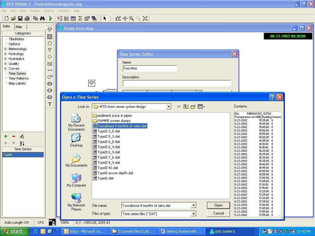
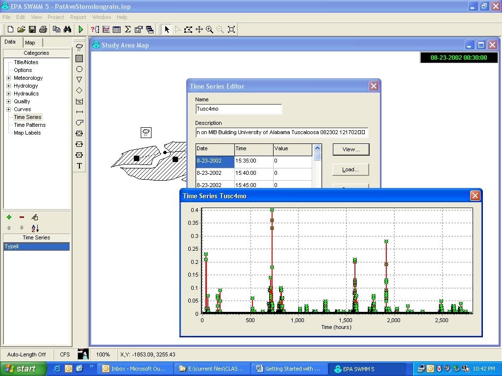
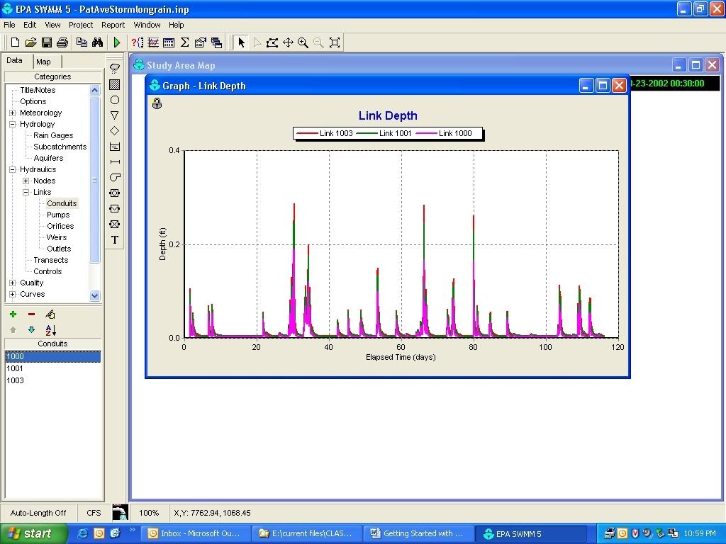
6 Birmingham Intensity - Duration - Frequency (IDF) Curve Basic Application of Rational Formula: Determine 10-yr (10% probability of being exceeded in any one year) flows at inlets to pipes: Pipe AB: inlet tc = 6 min; i = 7.4 in/hr; Q = CiA = (0.3)(7.4 in/hr)(3.1 acres) = 6.9 cfs Pipe BC: inlet tc = 8 min vs min, use 8 min; i = 6.6 in/hr; Q= [(3.1ac)(0.3)+(2.8ac)(0.4)] 6.6 in/hr = 13.5 cfs Pipe CD: inlet tc = 5 min vs vs , use 8.5 min; i = 6.3 in/hr; Q = [(3.1ac)(0.3)+(2.8ac)(0.4)+(2.1ac)(0.35)] 6.3 in/hr = 17.5 cfs The travel times in the pipes can only be calculated after the pipe sizes are selected and the velocities at the design flows are determined. 6

 in a residential area.")
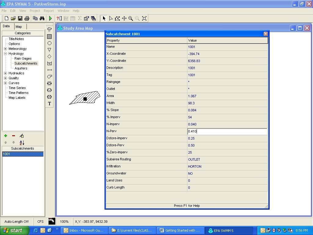
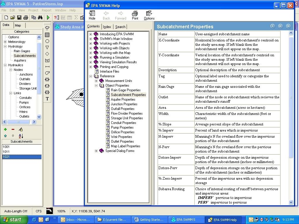
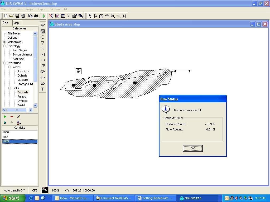
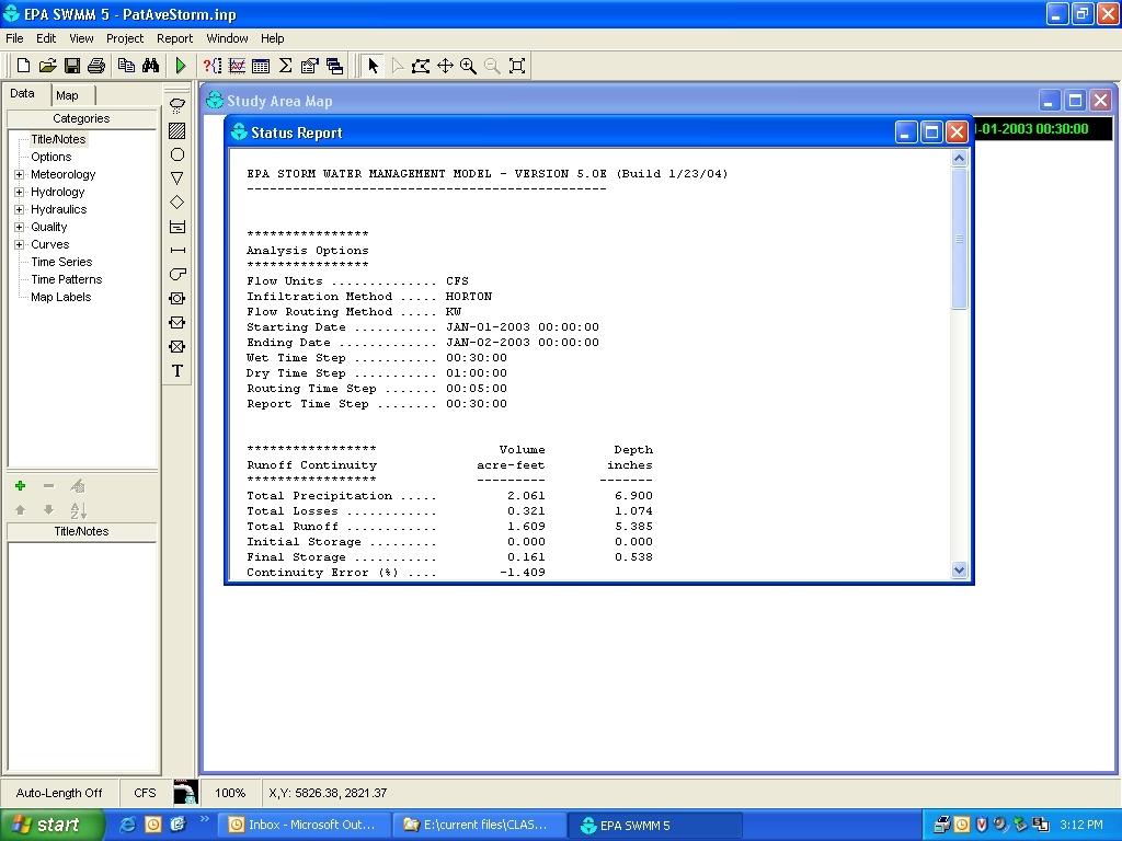
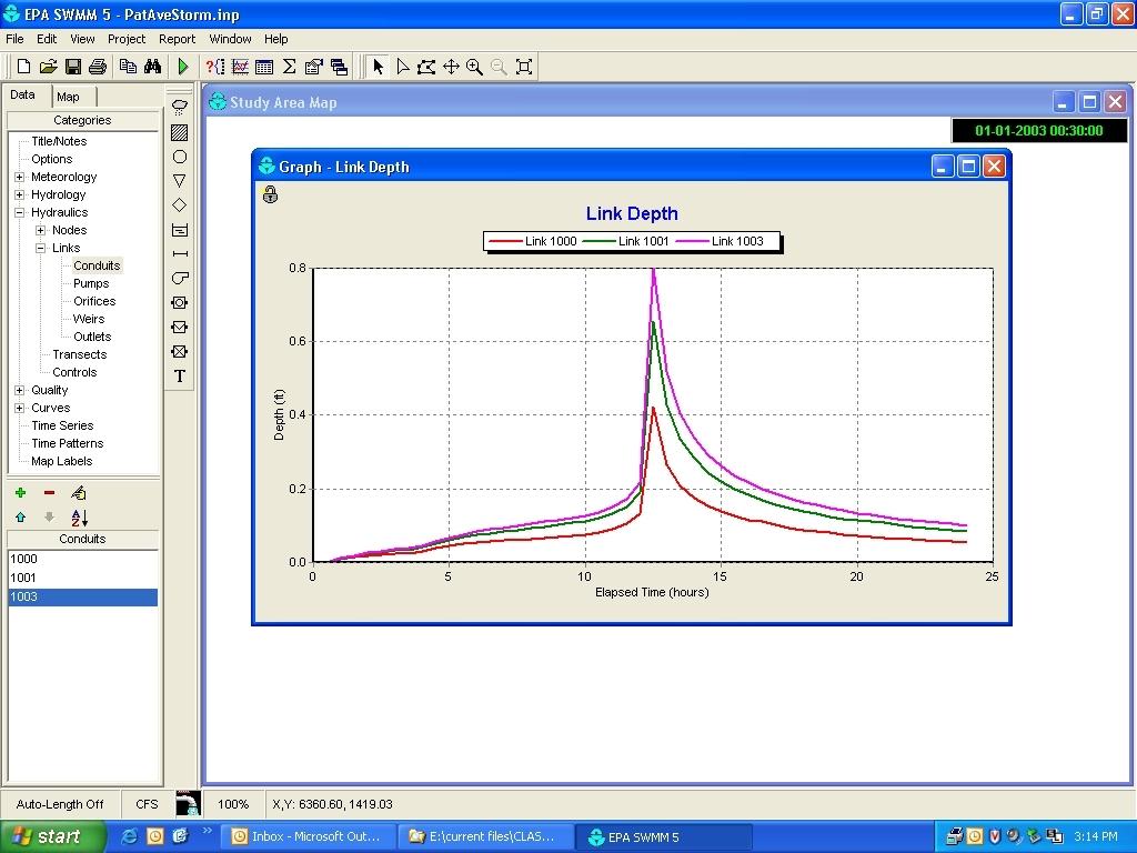
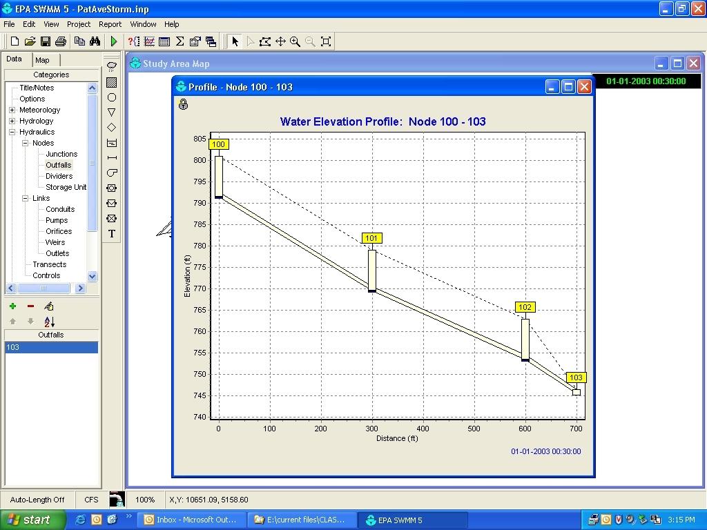
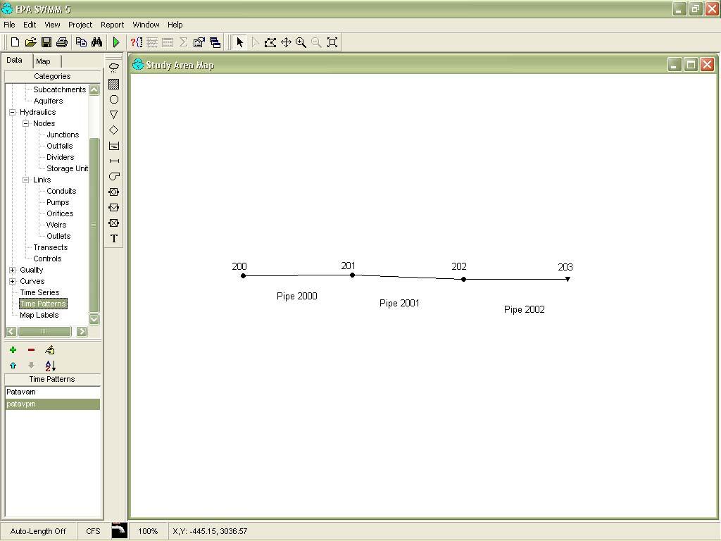
7 Pat Avenue storm sewer example Pat Avenue is located in Birmingham, AL. It consists of three subcatchments, three junctions (nodes) and two conduits (pipes) in a residential area. The water collected during a rainstorm is discharged to a main sewer trunk. 7
8 Site Information Area (Acres) Pipe length Slope (ft/ft) Imperv. (%) Runoff Coefficients for the Rational Formula for Different Hydrologic Soil Groups (A, B, C, D) and Slope Ranges (from McCuen, Hydrologic Analysis and Design. Prentice-Hall, Inc. 1998) Land Use A B C D Residential Lot, ⅛ acre Residential Lot, ¼ acre Residential Lot, ⅓ acre Residential Lot, ½ acre Residential Lot, 1 acre 0 2% 2 6% 6%+ 0 2% 2 6% 6%+ 0 2% 2 6% 6%+ 0 2% 2 6% 6% a b Subcatchment Commercial a Runoff coefficients for storm recurrence intervals less than 25 years. b Runoff coefficients for storm recurrence intervals of 25 years or longer. 8
9 Example of Rational Method Calculation for Area 1001 Drainage Area (assume: 10-year storm because street is a minor urban street and not a collector street) Drainage Area: 1.07 acres Watershed Slope: Hydrologic Soil Group C (assume/look up) Land Use Description: ½ acre lots Time of Concentration: 10 minutes Using T c = 10 minutes, i = 6.4 in/hr for 10-year storm Using ½-acre lot size, 6+% slope, C soil, C = 0.32 Peak Discharge = Q p = CiA Q p = (0.32)(6.4 in/hr)(1.07 acres) = 2.19 cfs Detailed Site Information Subcatchm ent Area (Acres) Slope (ft/ft) Rational C Inlet Tc (min) Travel time in pipe (min) Total Tc (min) Intensity (in/hr) Total Q at bottom of area (cfs) Tc gets larger and intensity gets smaller as the total drainage area increases 9
10 Conduit Information Conduit Shape Slope Length Manning s n 1000 Circular Circular Manning s Equation Diameter of a Pipe Flowing Full Using Manning s Equation for Flow These equations are for US Customary units! Use cfs for Q, and ft for D. Without the 1.49 in the denominator of the last expression, SI units can be used: m 3 /sec for Q and m for D D Q D n 4 4 nq 1.49S 1/ 2 4nQ 1.49 S 1/ 2 4nQ 1/ 1.49 S 5 / 3 4 nq 1/ 1.49 S 5 / 3 4 nq 1/ 1.49 S 2 D D D D 4 D 4 D 2 3 / 8 8 / 3 2 / 3 8 / 3 D 2 / 3 2 / 3 S 2 / 3 1/ 2 10
11 Storm Sewer Calculations Conduit Shape Slope Length Manning s n Total Q at end of pipe (cfs) 1000 Circular Circular Conduit Q (cfs) Calculated D Actual D Regulated D Q full (cfs) At outlet Sewers Flowing Partly Full From: Metcalf and Eddy, Inc. and George Tchobanoglous. Wastewater Engineering: Collection and Pumping of Wastewater. McGraw-Hill, Inc
12 Storm Sewer Calculations Conduit Q (cfs) Min. required pipe size Q full (cfs) Q/Q full d/d At outlet Conduit V/V full V full (ft/sec) V at peak flow (ft/sec) Travel time in pipe (min) At outlet Pipe Sizes Minimum size inches In many locations, the minimum size of a storm sewer pipe is regulated 12
13 Velocities Minimum velocity of 2.0 ft/sec (0.6 m/sec) with flow at ½ full or full depth Maximum average velocities of ft/sec ( m/sec) at design depth of flow Minimum and maximum velocities may be specified in state and local standards Slopes Sewers with flat slopes may be required to avoid excessive excavation where surface slopes are flat or the changes in elevation are small. In such cases, the sewer sizes and slopes should be designed so that the velocity of flow will increase progressively, or at least will be steady throughout the length of the sewer. 13


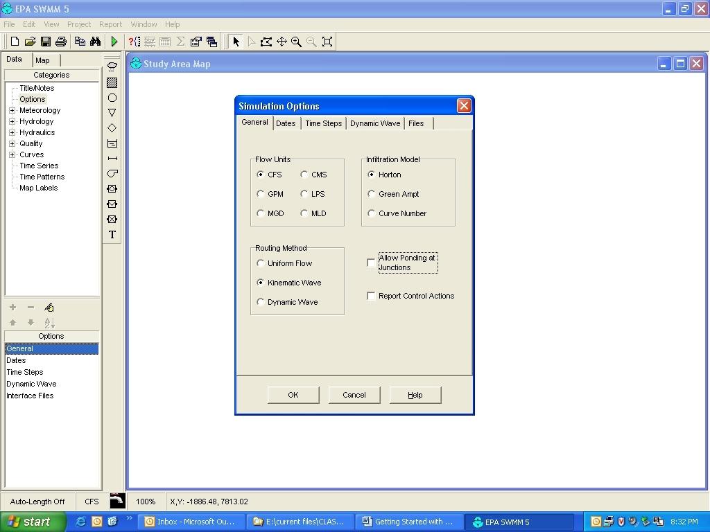
14 Getting Started with Storm and Sanitary Drainage Analysis using SWMM5 (Beta-E 01/23/04) The model can be downloaded by going to the EPA web site: PAT Avenue subcatchments, joints and conduits (in this example, another link, 1003, was created to allow all subwatershed flows to be combined before the outfall junction, now 103). 14
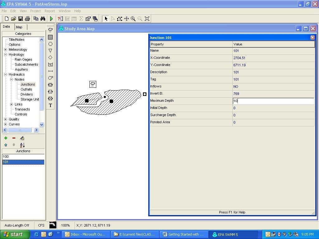
15 Pat Avenue Subcatchment information: Subcatch ment Area (Acres) Width Slope (ft/ft) Percentage imperviousness n Manning impervious n Manning pervious Subcatchment Horton maximum infiltration rate (in/hr) Horton minimum infiltration rate (in/hr) Horton decay coefficient (1/sec) Horton recovery coefficient (fraction) Max. volume (inches) Pat Avenue Junction Information: Junction Invert Elevation Maximum Depth Initial Depth Surcharge Depth Ponded Area (ft²) (Outfall) 745 n/a
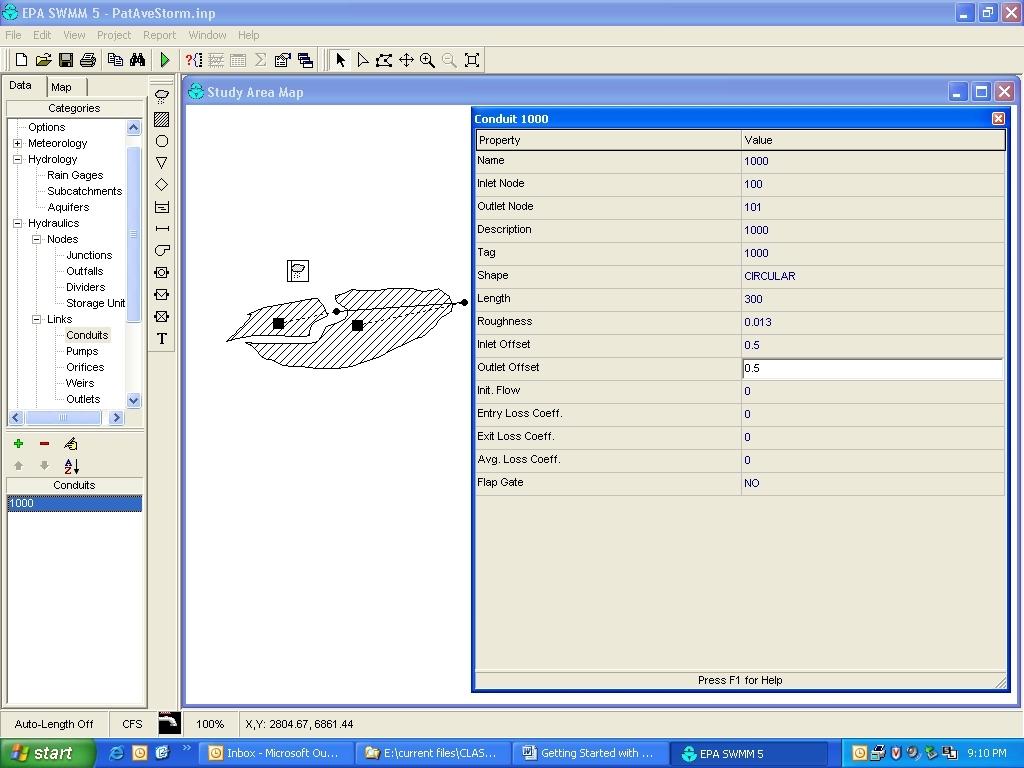
16 Pat Avenue Conduit Information: Conduit Shape Diameter Length n Manning Inlet invert height offset 1000 Circular Circular Circular Conduit Outlet invert height offset Initial flow (cfs) Entry loss coefficient Exit loss coefficient Average loss coefficient ft 801 ft 300 ft 779 ft 763 ft 10 ft D = 1ft n = ft D = 1ft n = outfall 16
17 17
18 18
19 19
20 20
21 21
22 22
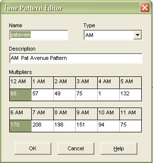
 Water Use (150 gal / day) Daily Wastewater Flow (90% of water used) Sewage (cfs) 200 0.98 3 96 14400 12960 0.020 201 1.")
23 Hello World Pat Avenue Sanitary Drainage Design Example Junction (Node) Area Served (ac) # Apt. Buildings Population (32 people / building) Water Use (150 gal / day) Daily Wastewater Flow (90% of water used) Sewage (cfs)
24 Junction Invert Elevation Maximum Depth Initial Depth Surcharge Depth Ponded Area (ft²) (Outfall) 750 n/a Conduit Shape Diameter Length n Manning Inlet invert height offset 2000 Circular Circular Circular Conduit Outlet invert height offset Initial flow (cfs) Entry loss coefficient Exit loss coefficient Average loss coefficient
25 25


26 Surcharged 1 ft. pipes Adequate capacity after enlarging pipes 2001 and 2002 to 1.5 ft in diameter 26
Runoff Calculations. Time of Concentration (T c or t c ) from one location to another within a watershed. Travel
 from one location to another within a watershed. Travel") Runoff Calculations Bob Pitt University of Alabama and Shirley Clark Penn State Harrisburg Time of Concentration and Travel Time (based on Chapter 3 of TR-55) Time of Concentration (T c ): time required
Runoff Calculations Bob Pitt University of Alabama and Shirley Clark Penn State Harrisburg Time of Concentration and Travel Time (based on Chapter 3 of TR-55) Time of Concentration (T c ): time required
Drainage Analysis. Appendix E
 Drainage Analysis Appendix E The existing and proposed storm drainage systems have been modeled with Bentley CivilStorm V8 computer modeling software. The peak stormwater discharge was determined for
RETENTION BASIN EXAMPLE
 -7 Given: Total Tributary Area = 7.5 ac o Tributary Area within Existing R/W = 5.8 ac o Tributary Area, Impervious, Outside of R/W = 0.0 ac o Tributary Area, Pervious, Outside of R/W = 1.7 ac o Tributary
FORT COLLINS STORMWATER CRITERIA MANUAL Hydrology Standards (Ch. 5) 1.0 Overview
 1.0 Overview") Chapter 5: Hydrology Standards Contents 1.0 Overview... 1 1.1 Storm Runoff Determination... 1 1.2 Design Storm Frequencies... 1 1.3 Water Quality Storm Provisions... 2 1.4 Design Storm Return Periods...
Chapter 5: Hydrology Standards Contents 1.0 Overview... 1 1.1 Storm Runoff Determination... 1 1.2 Design Storm Frequencies... 1 1.3 Water Quality Storm Provisions... 2 1.4 Design Storm Return Periods...
Basics of Wastewater Collection System
 Basics of Wastewater Collection System PDH: 3.0 Hours 1 OUTLINE Introduction Definition of Terms Types of Collections Systems Types of Sewers Shapes of Sewers Collection System Appurtenances Basic Considerations
Detention Pond Design Considering Varying Design Storms. Receiving Water Effects of Water Pollutant Discharges
 Detention Pond Design Considering Varying Design Storms Land Development Results in Increased Peak Flow Rates and Runoff Volumes Developed area Robert Pitt Department of Civil, Construction and Environmental
Introduction to Storm Sewer Design
 A SunCam online continuing education course Introduction to Storm Sewer Design by David F. Carter Introduction Storm sewer systems are vital in collection and conveyance of stormwater from the upstream
Rational Method Hydrological Calculations with Excel COURSE CONTENT
 Rational Method Hydrological Calculations with Excel Harlan H. Bengtson, PhD, P.E. COURSE CONTENT 1. Introduction Calculation of peak storm water runoff rate from a drainage area is often done with the
Learning objectives. Upon successful completion of this lecture, the participants will be able to describe:
 Solomon Seyoum Learning objectives Upon successful completion of this lecture, the participants will be able to describe: The different approaches for estimating peak runoff for urban drainage network
Module 10b: Gutter and Inlet Designs and Multiple Design Objectives
 Module 10b: Gutter and Inlet Designs and Multiple Design Objectives Bob Pitt University of Alabama and Shirley Clark Penn State Harrisburg Evening traffic plows through high water at the intersection of
INFLOW DESIGN FLOOD CONTROL SYSTEM PLAN PLANT GASTON GYPSUM POND ALABAMA POWER COMPANY
 INFLOW DESIGN FLOOD CONTROL SYSTEM PLAN PLANT GASTON GYPSUM POND ALABAMA POWER COMPANY Section 257.82 of EPA s regulations requires the owner or operator of an existing or new CCR surface impoundment or
the 2001 season. Allison brought high winds and street flooding to Houston, after
 Module 10b: Gutter and Inlet Designs and Multiple Design Objectives Bob Pitt University of Alabama and Shirley Clark Penn State Harrisburg Evening traffic plows through high water at the intersection of
INFLOW DESIGN FLOOD CONTROL SYSTEM PLAN PLANT BARRY ASH POND ALABAMA POWER COMPANY
 INFLOW DESIGN FLOOD CONTROL SYSTEM PLAN PLANT BARRY ASH POND ALABAMA POWER COMPANY Section 257.82 of EPA s regulations requires the owner or operator of an existing or new CCR surface impoundment or any
MODULE 1 RUNOFF HYDROGRAPHS WORKSHEET 1. Precipitation
 Watershed MODULE 1 RUNOFF HYDROGRAPHS WORKSHEET 1 A watershed is an area of land thaaptures rainfall and other precipitation and funnels it to a lake or stream or wetland. The area within the watershed
DRAINAGE CRITERIA MANUAL (V. 1) RUNOFF
 RUNOFF") Section CONTENTS Page RO- 1.0 OVERVIEW... 1 2.0 RATIONAL METHOD... 3 2.1 Rational Formula... 3 2.2 Assumptions... 4 2.3 Limitations... 4 2.4 Time of Concentration... 5 2.4.1 Initial Flow Time... 5 2.4.2
Section CONTENTS Page RO- 1.0 OVERVIEW... 1 2.0 RATIONAL METHOD... 3 2.1 Rational Formula... 3 2.2 Assumptions... 4 2.3 Limitations... 4 2.4 Time of Concentration... 5 2.4.1 Initial Flow Time... 5 2.4.2
CVEN 339 Summer 2009 Final Exam. 120 minutes allowed. 36 Students. No curve applied to grades. Median 70.6 Mean 68.7 Std. Dev High 88 Low 24.
 CVEN 339 Final Exam 120 minutes allowed 36 Students No curve applied to grades Median 70.6 Mean 68.7 Std. Dev. 13.7 High 88 Low 24.5 Name: CVEN 339 Water Resources Engineering Summer Semester 2009 Dr.
PRELIMINARY MUNICIPAL SERVICING REPORT NORTHWOODS SUBDIVISION. Prepared for: North Grassie Properties Inc.
 PRELIMINARY MUNICIPAL SERVICING REPORT SUBDIVISION Prepared for: North Grassie Properties Inc. Prepared by: Stantec Consulting Ltd. 905 Waverley St. Winnipeg, MB R3T 5P4 July 2012 File: 116808030 SUBDIVISION
APPENDIX G HYDRAULIC GRADE LINE
 Storm Drainage 13-G-1 APPENDIX G HYDRAULIC GRADE LINE 1.0 Introduction The hydraulic grade line is used to aid the designer in determining the acceptability of a proposed or evaluation of an existing storm
ENGN.4010 ENGINEERING CAPSTONE DESIGN Watershed Analysis. CiA
 RATIONAL METHOD Q CiA Where: Q = Maximum Rate of Runoff (cfs) C = Runoff Coefficient i = Average Rainfall Intensity (in/hr) A = Drainage Area (in acres) RATIONAL METHOD Assumptions and Limitations: Watershed
Extended Detention Basin Design
 Extended Detention Basin Design 1 Extended Detention 2 Ohio Department of Transportation 1 Extended Detention Basin L&D Vol. 2 Section 1117.3 Provides quality and quantity treatment 3 Extended Detention
WASTEWATER & STORM WATER COLLECTION AND REMOVAL
 CVE 471 WATER RESOURCES ENGINEERING WASTEWATER & STORM WATER COLLECTION AND REMOVAL Assist. Prof. Dr. Bertuğ Akıntuğ Civil Engineering Program Middle East Technical University Northern Cyprus Campus CVE
Hydrology Study. For Bella Terrazza Portion of Lot 1, Block 39, Subdivision of S Tract, Rancho El Cajon El Cajon, CA 92021
 Hydrology Study For Bella Terrazza Portion of Lot 1, Block 39, Subdivision of S Tract, Rancho El Cajon El Cajon, CA 92021 Prepared for Daryl Priest - Priest Development Corporation 124 West Main Street,
Hydrology for Drainage Design. Design Considerations Use appropriate design tools for the job at hand:
 Hydrology for Drainage Design Robert Pitt Department of Civil and Environmental Engineering University of Alabama Tuscaloosa, AL Objectives for Urban Drainage Systems are Varied Ensure personal safety
INFLOW DESIGN FLOOD CONTROL SYSTEM PLAN PLANT GREENE COUNTY ASH POND ALABMA POWER COMPANY
 INFLOW DESIGN FLOOD CONTROL SYSTEM PLAN PLANT GREENE COUNTY ASH POND ALABMA POWER COMPANY Section 257.82 of EPA s regulations requires the owner or operator of an existing or new CCR surface impoundment
Run-on and Run-off Control System Plan
 Run-on and Run-off Control System Plan CCR Temporary Storage Pad Lewis and Clark Station Prepared for Montana-Dakota Utilities Co. October 2016 Paul T. Swenson 2016.10.13 18:30:03-05'00' 234 West Century
HY-12 User Manual. Aquaveo. Contents
 Y-12 User Manual Aquaveo Contents Overview...2 Watershed Parameters...3 Channel Parameters...3 Storm Drain Parameters...3 Design of new systems...4 Analysis of existing systems...4 Steady flow...4 ydrographic
Report. Inflow Design Flood Control System Plan St. Clair Power Plant St. Clair, Michigan. DTE Energy Company One Energy Plaza, Detroit, MI
 Report Inflow Design Flood Control System Plan St. Clair Power Plant St. Clair, Michigan DTE Energy Company One Energy Plaza, Detroit, MI October 14, 2016 NTH Project No. 62-160047-04 NTH Consultants,
100-yr Design Runoff (cfs) Basin ID 103b A a B B C Totals
 Basin ID 103b A a B B C Totals") PROPOSED DEVELOPMENT The drainage for this site has been designed to be less than the maximum allowable runoff from each basin as stated in the Overall Rigden Farm drainage plan. Table 1 compares the actual
PROPOSED DEVELOPMENT The drainage for this site has been designed to be less than the maximum allowable runoff from each basin as stated in the Overall Rigden Farm drainage plan. Table 1 compares the actual
HYDROLOGIC-HYDRAULIC STUDY ISABELLA OCEAN RESIDENCES ISLA VERDE, CAROLINA, PR
 HYDROLOGIC-HYDRAULIC STUDY ISABELLA OCEAN RESIDENCES ISLA VERDE, CAROLINA, PR 1 INTRODUCTION 1.1 Project Description and Location Isabella Ocean Residences is a residential development to be constructed
The Islamic University of Gaza- Civil Engineering Department Sanitary Engineering- ECIV 4325 L5. Storm water Management
 The Islamic University of Gaza- Civil Engineering Department Sanitary Engineering- ECIV 4325 L5. Storm water Management Husam Al-Najar Storm water management : Collection System Design principles The Objectives
Inflow Design Flood Control System Plan
 Inflow Design Flood Control System Plan Scrubber Ponds Lewis and Clark Station Prepared for Montana-Dakota Utilities Co. October 2016 Paul T. Swenson 2016.10.14 17:54:29-05'00' 234 West Century Avenue
CEE 371 Water and Wastewater Systems
 Updated: 9 December 2009 CEE 371 Water and Wastewater Systems Print version Lecture #29 Wastewater Treatment: Sewer Design Reading: Chapter 10, pp.329-359 PBS: Poisoned Waters David Reckhow CEE 371 L#29
Storm Sewers, Page 2
 Storm Sewers storm sewer systems are dendritic systems used to collect and direct stormwater runoff storm sewer systems are integral components of any urban infrastructure curbs, gutters and storm inlets
Learn how to design inlet grates, detention basins, channels, and riprap using the FHWA Hydraulic Toolbox and WMS
 v. 11.0 WMS 11.0 Tutorial Learn how to design inlet grates, detention basins, channels, and riprap using the FHWA Hydraulic Toolbox and WMS Objectives Learn how to use several Hydraulic Toolbox calculators
Summary of Detention Pond Calculation Canyon Estates American Canyon, California
 July 15, 2015 Bellecci & Associates, Inc Summary of Detention Pond Calculation Canyon Estates American Canyon, California 1. Methodology: Method: Unit Hydrograph Software: Bentley Pond Pack Version 8i
Storm Sewer Design - Introduction
 Class 4 [1] Storm Sewer Design - Introduction As urban drainage can not be expected to accommodate all rainfall events, the first step in the design procedure is to select an appropriate design storm.
Table of Contents. Overview... 1
 Chapter 3 Chapter 3 Table of Contents Overview... 1 Rainfall... 2 3-2-1 Rainfall Depths and Intensities... 2 3-2-2 Design Storm Distribution for Colorado Urban Hydrograph Procedure (CUHP)... 5 3-2-3 Temporal
APPENDIX F RATIONAL METHOD
 7-F-1 APPENDIX F RATIONAL METHOD 1.0 Introduction One of the most commonly used procedures for calculating peak flows from small drainages less than 200 acres is the Rational Method. This method is most
Report. Inflow Design Flood Control System Plan Belle River Power Plant East China, Michigan. DTE Energy Company One Energy Plaza, Detroit, MI
 Report Inflow Design Flood Control System Plan Belle River Power Plant East China, Michigan DTE Energy Company One Energy Plaza, Detroit, MI October 14, 2016 NTH Project No. 62-160047-04 NTH Consultants,
Learning objectives. Upon successful completion of this lecture, the participants will be able to:
 Solomon Seyoum Learning objectives Upon successful completion of this lecture, the participants will be able to: Describe and perform the required step for designing sewer system networks Outline Design
CIE4491 Lecture. Quantifying stormwater flow Rational method
 CIE4491 Lecture. Quantifying stormwater flow Rational method 27-5-2014 Marie-claire ten Veldhuis, Watermanagement Department Delft University of Technology Challenge the future Robust method stationary
Table of Contents. Overview... 1
 Table of Contents Overview... 1 Rainfall... 2 3-2-1 Rainfall Depths and Intensities... 3 3-2-2 Design Storm Distribution for use with Colorado Urban Hydrograph Procedure (CUHP)... 5 3-2-3 Temporal Distribution...
TECHNICAL MEMORANDUM. SUBJECT: Determination of watershed historic peak flow rates as the basis for detention basin design
 TECHNICAL MEMORANDUM FROM: Ken MacKenzie and Ryan Taylor SUBJECT: Determination of watershed historic peak flow rates as the basis for detention basin design DATE: June 7, 2012 The purpose of this memorandum
10.0 Storm Sewer Systems
 October 2003 Chapter 10.0, Storm Sewer Systems Page 1 10.0 Storm Sewer Systems 10.1 Introduction A storm sewer system consists of a system of inlets, pipes, manholes, junctions, cleanouts, outlets, and
Section 600 Runoff Table of Contents
 Section 600 Runoff Table of Contents 601 INTRODUCTION...600-1 602 RATIONAL METHOD...600-1 602.1 Rational Method Formula...600-2 602.2 Time of Concentration...600-2 602.3 Intensity...600-4 602.4 Runoff
PRELIMINARY DRAINAGE REPORT FOR THE EDI MASTER PLAN
 PRELIMINARY DRAINAGE REPORT FOR THE EDI MASTER PLAN April 5, 2015 Wayne W. Chang, MS, PE 46548 Chang Civil Engineering Hydrology Hydraulics Sedimentation P.O. Box 9496 Rancho Santa Fe, CA 92067 (858) 692-0760
NCEES NCEES-PE. NCEES - PE Civil Engineering.
 NCEES NCEES-PE NCEES - PE Civil Engineering https://killexams.com/pass4sure/exam-detail/ncees-pe Question: 35 Which of the following assumptions regarding the compression strength of concrete used in reinforced
Chapter 6. Hydrology. 6.0 Introduction. 6.1 Design Rainfall
 6.0 Introduction This chapter summarizes methodology for determining rainfall and runoff information for the design of stormwater management facilities in the City. The methodology is based on the procedures
WinSLAMM v Program Modifications Final, 3/16/19
 WinSLAMM v 10.4.1 Program Modifications Final, 3/16/19 1. Printing Set up a printing option for.pdf files for input data and output summary data. 2. Added the Pipe input data to the printing input data
BMP Design Aids. w w w. t r a n s p o r t a t i o n. o h i o. g o v. Equations / Programs
 BMP Design Aids 1 Equations / Programs Outlet Discharge Equations Hydrograph and Pond Routing Programs USGS StreamStats 2 Ohio Department of Transportation 1 Training Intent Introduction and overview of
DERIVATION AND CALIBRATION OF VOLUME-BASED RUNOFF COEFFICIENTS FOR DENVER AREA, COLORADO
 DERIVATION AND CALIBRATION OF VOLUME-BASED RUNOFF COEFFICIENTS FOR DENVER AREA, COLORADO Prepared by Dr. James C.Y. Guo, P.E., Professor and Director, Civil Engineering, U of Colorado Denver James.Guo@UCDenver.edu
St. Boniface Industrial Park Phase 2 Municipal Servicing Report
 St. Boniface Industrial Park Phase 2 Municipal Servicing Report Prepared for: City of Winnipeg Prepared by: Stantec Consulting Ltd. File: 116809351 November 5, 2015 ST. BONIFACE INDUSTRIAL PARK PHASE 2
6 STOREY CONDOMINIUM 7480 DERRY ROAD WEST, MILTON
 6 STOREY CONDOMINIUM 7480 DERRY ROAD WEST, MILTON STORM WATER MANAGEMENT DESIGN BRIEF NEW DEVELOPMENT DRAINAGE SYSTEM REV 0 August 29, 2017 PREPARED BY: HALLEX PROJECT #170532 HALLEX NIAGARA HALLEX HAMILTON
PRELIMINARY DRAINAGE STUDY
 PRELIMINARY DRAINAGE STUDY For 34 th & J Residences 3402 J St. San Diego, CA 92102 A.P.N 545-250-08 Prepared By: Kenneth J. Discenza, P.E. Site Design Associates, Inc. 1016 Broadway, Suite A El Cajon,
TECHNICAL BULLETIN. Synthetic Turf Athletic Field Drainage Design Assistance
 TECHNICAL BULLETIN Synthetic Turf Athletic Field Drainage Design Assistance The SportsEdge HQ geocomposite strip drain products are engineered specifically for use in synthetic turf athletic field base
WinSLAMM v Program Modifications Final, 12/12/17
 WinSLAMM v 10.3.4 Program Modifications Final, 12/12/17 1. Corrected an error in the Biofilter caused by an improperly defined variable that caused an overflow during very long model runs. 2. Corrected
IBS Site Drainage: Senior Design Project
 IBS Site Drainage: Senior Design Project Len Wright, Ph.D., PE Lecturer, CEAE Wright.Len@gmail.com September 11, 2008 mwsw204i1.ppt/1 OUTLINE Motivation for Stormwater Management Quantity (both onsite,
DIVISION 5 STORM DRAINAGE CRITERIA
 DIVISION 5 STORM DRAINAGE CRITERIA Section 5.01 GENERAL The following storm drainage design criteria shall apply to all storm drainage designs in the City. Additional design criteria are specified in the
Chapter Introduction. 5.2 Computational Standard Methods HYDROLOGY
 Chapter 5. HYDROLOGY 5.1 Introduction The definition of hydrology is the scientific study of water and its properties, distribution, and effects on the earth s surface, in the soil and the atmosphere.
LAKE COUNTY HYDROLOGY DESIGN STANDARDS
 LAKE COUNTY HYDROLOGY DESIGN STANDARDS Lake County Department of Public Works Water Resources Division 255 N. Forbes Street Lakeport, CA 95453 (707)263-2341 Adopted June 22, 1999 These Standards provide
HYDROLOGY STUDY PREPARED FOR: MARKHAM PERRIS LLC 302 WEST FIFTH STREET, SUITE 103 SAN PEDRO, CA (310) FOR THE PROJECT:
 FOR THE PROJECT:") HYDROLOGY STUDY PREPARED FOR: MARKHAM PERRIS LLC 302 WEST FIFTH STREET, SUITE 103 SAN PEDRO, CA 90731 (310) 241-2992 FOR THE PROJECT: PERRIS VALLEY COMMERCE CENTER BUILDING PERRIS, CALIFORNIA PROJECT NUMBER:
HYDROLOGY STUDY PREPARED FOR: MARKHAM PERRIS LLC 302 WEST FIFTH STREET, SUITE 103 SAN PEDRO, CA 90731 (310) 241-2992 FOR THE PROJECT: PERRIS VALLEY COMMERCE CENTER BUILDING PERRIS, CALIFORNIA PROJECT NUMBER:
Module 3: Rainfall and Hydrology for Construction Site Erosion Control
 Module 3: Rainfall and Hydrology for Construction Site Erosion Control Robert Pitt Department of Civil, Construction, and Environmental Engineering University of Alabama Tuscaloosa, AL Rainfall and Hydrology
January 20, Nate Hatleback Project Manager, City of Thornton Development Engineering 9500 Civic Center Drive Thornton, CO (303)
") January 20, 2017 Nate Hatleback Project Manager, City of Thornton Development Engineering 9500 Civic Center Drive Thornton, CO 80229 (303) 538-7694 RE: Riverdale Five Retail Drainage Conformance Letter
January 20, 2017 Nate Hatleback Project Manager, City of Thornton Development Engineering 9500 Civic Center Drive Thornton, CO 80229 (303) 538-7694 RE: Riverdale Five Retail Drainage Conformance Letter
Applying the Water Quality Volume
 Applying the Water Quality Volume Justin Reinhart, PE Division of Surface Water Northeast Ohio Stormwater Training Council Cleveland, Ohio & Richfield, Ohio July 12, 2018 July 25, 2018 Post-Construction
Facilities Development Manual
 State of Wisconsin Department of Transportation Facilities Development Manual ORIGINATOR Director, Bureau of Highway Development PROCEDURE 13-25-35 CHAPTER 13 Drainage SECTION 25 Storm Sewer Design SUBJECT
HYDROLOGY WORKSHEET 1 PRECIPITATION
 HYDROLOGY WORKSHEET 1 PRECIPITATION A watershed is an area of land that captures rainfall and other precipitation and funnels it to a lake or stream or wetland. The area within the watershed where the
SECTION 4 STORM DRAINAGE
 4.01 GENERAL SECTION 4 STORM DRAINAGE These standards shall provide minimum requirements for the design of Storm Drainage and related appurtenances within the City of West Sacramento rights of way and
INFLOW DESIGN FLOOD CONTROL SYSTEM PLAN 40 C.F.R. PART PLANT YATES ASH POND 3 (AP-3) GEORGIA POWER COMPANY
 GEORGIA POWER COMPANY") INFLOW DESIGN FLOOD CONTROL SYSTEM PLAN 40 C.F.R. PART 257.82 PLANT YATES ASH POND 3 (AP-3) GEORGIA POWER COMPANY EPA s Disposal of Coal Combustion Residuals from Electric Utilities Final Rule (40 C.F.R.
INFLOW DESIGN FLOOD CONTROL SYSTEM PLAN 40 C.F.R. PART 257.82 PLANT YATES ASH POND 3 (AP-3) GEORGIA POWER COMPANY EPA s Disposal of Coal Combustion Residuals from Electric Utilities Final Rule (40 C.F.R.
STORMWATER HYDROLOGY
 ..CHAPTER.. STORMWATER HYDROLOGY 3.1 Introduction to Hydrologic Methods Hydrology is the science dealing with the characteristics, distribution, and movement of water on and below the earth's surface and
November 21, City of Thornton 9500 Civic Center Drive Thornton, CO (303) RE: Maverik Thornton, CO - Drainage Report
 RE: Maverik Thornton, CO - Drainage Report") November 21, 2016 City of Thornton 9500 Civic Center Drive Thornton, CO 80229 (303) 538-7295 RE: Maverik Thornton, CO - Drainage Report As per your request, we are submitting to you the drainage report
November 21, 2016 City of Thornton 9500 Civic Center Drive Thornton, CO 80229 (303) 538-7295 RE: Maverik Thornton, CO - Drainage Report As per your request, we are submitting to you the drainage report
Introduction to Hydrology, Part 2. Notes, Handouts
 Introduction to Hydrology, Part 2 Notes, Handouts Precipitation Much of hydrology deals with precipitation How much? How frequently/infrequently? What form? How quickly? Seasonal variation? Drought frequency?
Water Resources Management Plan
 P L Y M O U T H M I N N E S O T A Appendix D: The developed a to analyze and minimize the impact of existing and future development on the City s natural resources. It is important to the City to have
COON CREEK WATERSHED DISTRICT PERMIT REVIEW. Spring Lake Park Schools Westwood Middle School st Avenue NE, Spring Lake Park, MN 55432
 PAN 16-112, Westwood Middle School, Page 1 of 6 COON CREEK WATERSHED DISTRICT PERMIT REVIEW MEETING DATE: August 22, 2016 AGENDA NUMBER: 10 FILE NUMBER: 16-112 ITEM: Westwood Middle School RECOMMENDATION:
iswm TM Technical Manual Hydrology:
 : 1.0 2.0 Downstream Assessment 3.0 Streambank Protection 4.0 Water Balance 5.0 Rainfall Tables 6.0 Hydrologic Soils Data Table of Contents 1.0... HO-1 1.1 Estimating Runoff... HO-1 1.1.1 Introduction
Particulate Transport in Grass Swales
 Particulate Transport in Grass Swales Robert Pitt, P.E., Ph.D., DEE and S. Rocky Durrans, P.E., Ph.D. Department of Civil, Construction, and Environmental Engineering The University of Alabama Yukio Nara
Module 3 and Module 4 Watershed Analysis and RUSLE Calculation. Noboru Togawa. Presented to: Dr. Pitt Construction Site Erosion Control
 Module 3 and Module 4 Watershed Analysis and RUSLE Calculation by Presented to: Dr. Pitt Construction Site Erosion Control Department of Civil, Construction, and Environmental Engineering The University
Use of IDF Curves Design of a roof drainage system
 Use of IDF Curves Design of a roof drainage system Your engineering firm is currently planning the construction of a residential apartment building in Davos, Switzerland. Your task is to design the roof
Analysis and Simulation of Drainage Capacity of Urban Pipe Network
 Research Journal of Applied Sciences, Engineering and Technology 6(3): 387-392, 2013 ISSN: 2040-7459; e-issn: 2040-7467 Maxwell Scientific Organization, 2013 Submitted: July 17, 2012 Accepted: August 28,
Hydrology Study. Ascension Heights Subdivision Ascension Drive at Bel Aire Road San Mateo, California (Unincorporated)
") Hydrology Study Ascension Heights Subdivision Ascension Drive at Bel Aire Road San Mateo, California (Unincorporated) Prepared for San Mateo Real Estate & Construction March 9, 21 Rev. 1 11-8-211 Rev.
Hydrology Study Ascension Heights Subdivision Ascension Drive at Bel Aire Road San Mateo, California (Unincorporated) Prepared for San Mateo Real Estate & Construction March 9, 21 Rev. 1 11-8-211 Rev.
La Riereta Catchment Sant Boi de Llobregat
 La Riereta Catchment Sant Boi de Llobregat Final Report Team 2 Enrique Amaya (COL) Lilian Yamamoto (BRA) Martín Pez (ARG) Sergio Esquivel (MEX) Instructor: José Macor Summary Contents 1. Introduction...
Sump Pumps Office procedures for the Drainage & Grading section
 County of Los Angeles Department of Public Works Building and Safety Division Grading and Drainage Section Sump Pumps Office procedures for the Drainage & Grading section Introduction This manual provides
Table of Contents CHAPTER. Chapter 2 Hydrologic Analysis. 2.1 Estimating Runoff
 CHAPTER Table of Contents 2 Chapter 2 Hydrologic Analysis 2.1 Estimating Runoff 2.1.1 Introduction to Hydrologic Methods...2.1-1 2.1.2 Symbols and Definitions...2.1-4 2.1.3 Rainfall Estimation...2.1-5
GIS Enabled Automated Culvert Design
 GIS Enabled Automated Culvert Design Andrew Graettinger, PhD Ashton Greer, Leah Clifton, Zachary Wilbanks, and Bradford Wilson The University of Alabama Civil, Construction, and Environmental Engineering
Wastewater Collection System
 WASTEWATER COLLECTION SYSTEM CE 370 1 Wastewater Collection System The function of the collection system is to collect the wastewater from residential, commercial, and industrial areas within the service
RE: Final Drainage Letter: Northwest Aurora Alley Improvements 2016
 April 12, 2016 Mr. Craig Perl, P.E. Senior Engineer City of Aurora Public Works Department 15151 E. Alameda Parkway Aurora, CO 80012 RE: Final Drainage Letter: Northwest Aurora Alley Improvements 2016
Remediation and Treatment Technology Development and Support for DOE Oak Ridge Office: XPSWMM Model Configuration
 TECHNICAL PROGRESS REPORT Remediation and Treatment Technology Development and Support for DOE Oak Ridge Office: Date submitted: September 14, 2012 Principal Investigators: Leonel E. Lagos, Ph.D., PMP
Appendix E.2 Preliminary Hydrology Report
 Appendix E.2 Preliminary Hydrology Report PRELIMINARY HYDROLOGY STUDY HARVARD WESTLAKE SCHOOL PARKING STRUCTURE 3700 Coldwater Canyon North Hollywood, CA 91604 KPFF Job # 109046 August 12, 2013 CLIENT:
APPENDIX K OPERATIONS AND FINAL COVER SURFACE WATER MANAGEMENT SYSTEM DESIGN
 ONONDAGA LAKE SEDIMENT CONSOLIDATION AREA CIVIL & GEOTECHNICAL FINAL DESIGN APPENDIX K OPERATIONS AND FINAL COVER SURFACE WATER MANAGEMENT SYSTEM DESIGN PARSONS P:\Honeywell -SYR\44483 - Lake Detail Design\9
INITIAL RUN-ON AND RUN-OFF CONTROL PLAN 40 C.F.R. PART 257
 INITIAL RUN-ON AND RUN-OFF CONTROL PLAN 40 C.F.R. PART 257.81 HUFFAKER ROAD (PLANT HAMMOND) PRIVATE INDUSTRIAL LANDFILL (HUFFAKER ROAD LANDFILL) GEORGIA POWER COMPANY EPA s Disposal of Coal Combustion
Stormwater Treatment Measure Sizing and Design Considerations SMCWPPP C.3 Workshop June 21, 2017
 Stormwater Treatment Measure Sizing and Design Considerations SMCWPPP C.3 Workshop June 21, 2017 Jill Bicknell, P.E., EOA, Inc. Presentation Overview Sizing/Design of Self Treating and Self Retaining Areas
Inflow Design Flood Control System Plan
 Inflow Design Flood Control System Plan Scrubber Ponds Lewis & Clark Station Prepared for Montana-Dakota Utilities Co. November 2018 234 West Century Avenue Bismarck, ND 58503 701.255.5460 www.barr.com
Using Sanitary Sewer I/I Field Data to Calibrate a Storm Sewer Model
 15 Using Sanitary Sewer I/I Field Data to Calibrate a Storm Sewer Model Josh A. Reinicke, Marc A. Lehmann and C. Timothy Fallara Since 1992, the City of Columbus Division of Sewerage and Drainage (DOSD)
PRELIMINARY DRAINAGE STUDY REPORT ARBOR VILLAS
 PRELIMINARY DRAINAGE STUDY REPORT FOR CARSON CITY, NEVADA Prepared for: Capstone Communities 9441 Double Diamond Pkwy #14 Reno, Nevada 89521 Prepared by: Manhard Consulting Ltd. 985 Double R Boulevard
Design of Stormwater Wetlands
 Hydraulic & Hydrologic Stormwater Engineering Design of Stormwater Wetlands Jon Hathaway, EI Extension Associate NCSU Bio. And Ag. Engineering 6 Step Process 1. Watershed Analysis (Runoff Volume and Peak
APPENDIX IV. APPROVED METHODS FOR QUANTIFYING HYDROLOGIC CONDITIONS OF CONCERN (NORTH ORANGE COUNTY)
") APPENDIX IV. APPROVED METHODS FOR QUANTIFYING HYDROLOGIC CONDITIONS OF CONCERN (NORTH ORANGE COUNTY) Hydromodification design criteria for the North Orange County permit area are based on the 2- yr, 24-hr
APPENDIX IV. APPROVED METHODS FOR QUANTIFYING HYDROLOGIC CONDITIONS OF CONCERN (NORTH ORANGE COUNTY) Hydromodification design criteria for the North Orange County permit area are based on the 2- yr, 24-hr
APPENDIX J-3. Orcem Stormwater Management and Treatment Facilities Design Summary
 APPENDIX J-3 Orcem Stormwater Management and Treatment Facilities Design Summary Stormwater Management & Treatment Facilities Design Summary INTRODUCTION KPFF Consulting Engineers has compiled this report
2. DEFINITIONS. American Association of State Highway and Transportation Officials.
 2. DEFINITIONS 2.010 Definitions [See Amendment 2] In addition to words and terms that may be defined elsewhere in this manual, the following words and terms shall have the meanings defined below: AASHTO:
Chapter 25. Techniques Used in an Urban Watershed Planning Study Introduction. K. R. Avery andy. 0. LaBombard
 Chapter 25 Techniques Used in an Urban Watershed Planning Study K. R. Avery andy. 0. LaBombard For planning level studies of urban flooding, it is important to obtain reasonable estimates of hydraulic
The site slopes generally from the southwest to northeast at approximately 3.7 percent.
 March 3, 2017 Nate Hatleback Project Manager, City of Thornton Development Engineering 9500 Civic Center Drive Thornton, CO 80229 (303) 538-7694 RE: Riverdale Five Retail Drainage Conformance Letter Dear
Preliminary Drainage Analysis
 Preliminary Drainage Analysis Tanimura and Antle Employee Housing Town of Spreckels County of Monterey, California LIB150205 May 29, 2015 Prepared For: Tanimura and Antle Produce Prepared By: 9699 Blue