8.4.2 Steady flow: Hooghoudt equation
|
|
|
- Quentin Dalton
- 6 years ago
- Views:
Transcription
1 8.4.2 Steady flow: Hooghoudt equation As explained in Section 1.1, steady flow does not,. in reality, occur. At the end of tail recession, however, because of a small amount of seepage, the flow of some drains (Group 2) approximates steady flow. In such periods, i.e. when the fluctuation of the groundwater table is small and the discharge is almost constant, the Hooghoudt equation can be used to derive the hydraulic conductivity. As the thickness of the aquifer below drain level can be neglected, the Hooghoudt equation (1) can be simplified to s=- 4 Kh2 L2 This equation is similar to the Boussinesq expression for the discharge (Eq. 1 I ). Solving Eq. (16) for K yields: To determine the K-values during the desalinization process, several periods with almost steady-state conditions were selected. The results are given in Table 8.5 and can be compared with those determined with Eq.(ll). TABLE 8.5 K-values derived according to Eq.(16) No.of Depth of Period drain the layer group h 6 K m m "/day mlday 3-4 Pebr.'78 2 claylgravel O. 37 O July '75 2 claylgravel O Jan. '76 2 claylgravel O. 32 I. 14' Febr.'76 2 claylgravel I. 19l Aug. '76 2 claylgravel o ' Some contribution of flow kzm drain level 202
2 The analysis with the Hooghoudt equation confirms the results obtained with the equations for unsteady flow. If the drains are not located exactly on the impervious layer but somewhat above it, the influence of the flow below drain level will show up in apparently higher K-values for the layer above drain depth. The higher the h-value used in the calculation, the lower the influence of flow below drain level and consequently the smaller the error Hydraulic conductivity of the less pervious layer At the end of tail recession the piezometers placed at a depth of 3.5 m showed a higher water level than those placed at drain depth. This difference was observed in the three piezometer lines installed at the Alera field. There is no clear explanation for this difference because below drain level the soil is uniformly compact silty clay down to the impervious mudstone and no pervious layers were detected. However, as a low discharge was observed at the end of tail recession, the hydraulic gradient must have caused an upward flow. Various periods could therefore be selected in which the vertical hydraulic conductivity of the less pervious layer below drain level could be determined. Darcy's law can be applied to vertical flow: where v = flow rate = discharge per unit area (m/day) K' * hydraulic conductivity for vertical flow (m/day) 203
3 Ah = hydraulic head difference between the 3.5 m deep layer and drain level (m) D' = thickness of the layer between 1.5 m and 3.5 m (m) c = D'/K' hydraulic resistance of the less pervious layer (days) Table 8.6 shows the results obtained. The average KI-value of the less pervious layer is about m/day, which is at least 10 times smaller than that of the overlying layer above drain level. The layer below 1.5 m can therefore be considered impervious for flow towards drains, thereby confirming the conclusions of the study of groundwater flow. TABLE 8.6 Period K-values of the less pervious layer h3.5' h1.51 Ah D' S C K' m m m m =/day days mlday 9-11 Dec.' Feb.' Mar.' I Mar.' I Reference Zevel = depth of the impervious mudstone 13.5 ml To summarize, a value of 0.6 m/day can be used for the hydraulic conductivity of the soil profile between a depth of 0.5 m and drain level. Below drain level the soil is considered impervious. The permeability of the upper layer (0-50 cm) is about 1.5 m/day. Hence, if the water table is shallow after heavy rainfall or irrigation, a value of 1 "day can be used for the hydraulic conductivity of the soil profile. 204
4 ~ Comparison of the results obtained During the experimental period the hydraulic conductivity for different depths of the groundwater table was measured by the auger hole method. The hydraulic conductivity above the water table was estimated by the inversed auger hole method. In addition, undisturbed soil cores were taken in horizontal and vertical directions to measure the hydraulic conductivity in the laboratory. The object of these direct measurements of hydraulic conductivity was to compare field and laboratory methods in which only a small body of soil is measured, with large-scale field determinations that use the hydraulic headfdischarge analysis. This comparison could by useful in drainage projects for which only direct measurements are available. The average result obtained by the auger hole method (Table 8.7) was lower than that derived from the hydraulic head discharge analysis:0.2 mfday versus 0.6 mfday. TABLE 8.7 Hydraulic conductivity measured by the auger hole method No. of drain group Date Water table depth m Depth of the hole m K mlday 1 clay 2 clay/gravel 3 PVC/gravel October '76 October '76 October ' I.4 I O. I o PVC 6 PVClesp. 7 Pvc/coco 8 clay/gravel October '76 October '76 October '76 October ' I o I o O. I o
5 Table 8.7 shows that the K-values measured in fields where the drains function properly, are generally higher than those measured in fields whose drains have a high entrance resistance and where the water table seldom drops below 1 m. No satisfactory results were obtained with the inversed auger hole method used above the water table, since hardly any fall of water level was observed in the "pour-in holes". Augering in these silty clay soils may have sealed the soil pores. The results obtained by laboratory measurements in undisturbed soil cores (Table 8.8) show a greater variability and are even lower than those measured by the auger hole method. Nevertheless, they reveal that the soil is anisotropic, since the hydraulic conductivity in vertical direction is always higher than that in horizontal direction, probably due to the presence of root-holes and cracks. They also confirmed the decrease of hydraulic conductivity with depth. TABLE 8.8 Laboratory determinations of the hydraulic conductivity in undisturbed soil cores Depth m Direction O O horizontal vertical horizontal vertical horizontal ver tical horizontal vertical horizontal vertical horizontal vertical O o. 060' O. 015 O o o. 020 ' after subsoi~ing 206
6 conductivity has been calculated from the experimental fields, the auger hole method can be used to estimate the hydraulic conductivity at a large number of sites for use in a later phase of large-scale drainage projects. 8.5 Determination of the entrance resistance In the proximity of the drain the groundwater flow has to overcome an extra resistance because the drain pipes are not pervious over their entire surface; water enters only through the joints of the clay tile drains or through the perforations of the plastic pipes. The entrance resistance can be expressed by the following equation (Engelund 1957, Cavelaars 1967): h. h. w ='= 2 e q SL where 9 S L h. e ' 2 discharge per unit length of drain (m /day) discharge per unit area (m/day) drain spacing (m) difference in hydraulic head between the drain trench and the tile (m) entrance resistance (day/m) The entrance resistance is inversely proportional to the hydraulic conductivity of the soil in the proximity of the drain, or a we = - K 207
7 where K a = hydraulic conductivity of the medium (m/day) = factor depending on the type of drain pipe Equation (18) can be used to calculate the entrance resistance if the head loss between the edge of the drain trench and the drain pipe, and its corresponding discharge, are known. The difference in hydraulic head was determined by two methods. The first consisted of a direct reading of the piezometers installed in the drain trench and on the drain itself; the second (indirect) method was by calculation once the position of the groundwater table was known Direct method of determining the We value The direct method is based on the correlation between the discharge per unit length (sl) and the head loss between the edge of the drain trench and the drain (hi). by: The W -value must be equal to the slope of the straight line expressed h. = We (sl) (20) 1 The values of h. were plotted against the corresponding values of sl and the line through the points was calculated by linear regression. The slope of this straight line equals the entrance resistance W (Fig.8.21). e For each combination of drainage and filter materials, calculations were made seasonally. The observation period commenced in October For each period analysed at least 20 pairs of observations were compa- red. These observations pertain to periods with a falling water table. A few determinations in which the correlation coefficient was less than 0.9 were ignored. 208
8 hi (mm) 160 O Ò IO Ó!b &I 70 eb 9Ò sl(mm/doy.mj Fig.8.21: CaZcuZation of the We-vaZue with the direct method. The head loss near the drain (hi) was obtained from the difference between the readings in the piezometer installed 0.20 m from the drain and that on the drain itself (Fig.7.16). An average value was taken for h. from two observations made in piezometers placed at both sides of the drain. For drains with a length of 250 m an average value was adopted from readings in their two piezometer 1 ines. The expression for the regression lines obtained reads as follows: hi = We SL + a. From a theoretical point of view, a. should equal zero because the hydraulic head should be zero when there is no discharge. Figure 8.21, however, shows that, when the drain discharge becomes zero, there is still a difference in hydraulic head between the piezometer 0.20 m from the drain and the piezometer on the drain. 209
9 The existence of this residual value a may be due to two factors. One O is that the drain is located in a less pervious layer, and the other is that the piezometer 0.20 m from the drain was not placed inside the trench but slightly outside it, thereby yielding a higher value for h. (Fig.8.22). The W -values for successive periods are presented in Table 8.9 and e concern all the combinations of drainage and filter materials except PVC pipes with straw cover (Drain Group 51, which did not function properly because the water flow inside the pipe was impeded. Table 8.9 allows the conclusion that the entrance resistance remained fairly constant during the period under analysis. Nevertheless, the increase in entrance resistance (Fig.8.23) for the combination PVC/esparto shows that the esparto filter gradually becomes less pervious. The data from the PVC/cocos were somewhat irregular but show a similar tendency towards increasing W -values. e These results indicate that the best combination for the soils of the Alera field is clay pipes with gravel cover. These materials have the lowest entrance resistance (We = 2 day/m) and the highest durability. Corrugated PVC pipes with gravel cover can also be used although their entrance resistance is more than twice that of the clay pipes with gravel cover (W = 4.6 days/m). It must be taken into account that the exterior e
10 diameter of the plastic pipes is 5 cm, whereas the diameter of the clay tiles is 8 cm. It may well be that the entrance resistance of greater dia- meter PVC-pipe is lower. Table 8.9 Entrance resistance values (We, days/m) Year Season No. of drain Group I clay clay/gravel PVC/gravel PVC PVC/esparto PVClcocos clay/gravel 1974 Autumn 8.4 I I975 Winter 9. O Spring Summer 5. O Autumn l Winter o 1.5 Summer Autumn Winter l Spring 6.8 O I Summer Mean entrance resistance (x) 5.2 I Standard deviat- Number of periods I.o less than 20 pairs of observations no average has been calculated since We increases lsith time (Fig. 8.23: Fig.8.23: Increase of the We-Value with time (PVC/esparto drains
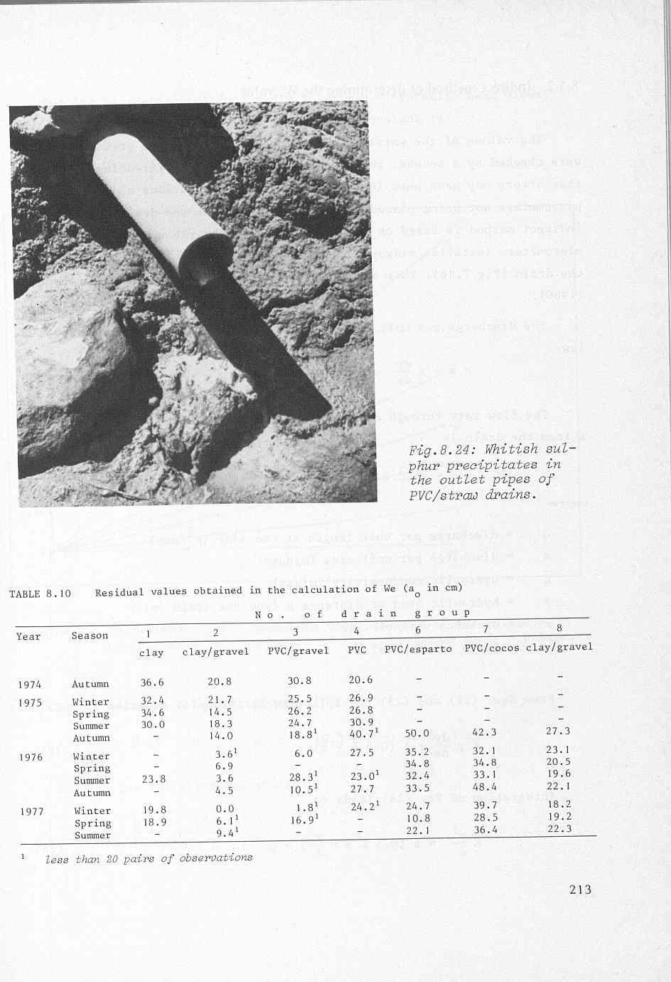
11 Clay pipes without gravel have almost the same entrance resistance as PVC pipes with gravel (We 5.2 daysh). (We Corrugated PVC pipes without a filter show a high entrance resistance 13 dayslm). Plastic pipes with cocos and esparto filters show an even higher entrance resistance than pipes without filters. The PVC/esparto drains initially had a lower entrance resistance than the filterless plastic drains, but the W -value gradually increased (Fig.8.23). Obviously there is no e advantage to be gained in using this envelope. Although the increase in the W -value of PVC/cocos drains is not so e clearly manifest, a similar tendency exists. Barley straw is not suitable as cover material since it rots easily and clogs the pipe.these drains show very small but long-lasting discharges and consequently the fall of the water table is slow. The drainage water smells of H S and forms a precipitate of 2 sulphur at the drain outlets. Obviously, microbiological processes cause a rapid decomposition of the straw envelope, at the same time reducing sulphates (abundantly present in the groundwater) to H2S. At the outlets, sulphur bacteria oxidize H2S to H O and S, 2 forming whitish and sticky precipitates in the outlet pipes (Fig.8.24). The a -value of Eq.(21) was not constant for every drain group. O Its variation during the observation period is shown in Table A de- crease in the a -value can be observed for those combinations that had O the lowest entrance resistance and showed a deeper and more frequent fall of the water table, which can probably be explained by an improved permeability in the drain trench. 212
12
13 T Indirect method of determining the We value The values of the entrance resistance obtained in the previous section were checked by a second, indirect, method. The reason for doing so was that errors may have been introduced into the calculations because of the piezometers not being placed exactly at the edge of the drain trench. The indirect method is based on the shape of the water table measured in the piezometers installed midway between drains (10 m>, at 5 m, and at I m from the drain (Fig.7.16). This analysis was originally developed by van Hoorn (1960). law: The discharge per unit length can be calculated by applying Darcy's q = - K * dx y (22) The flow rate through a section of the region of flow at a distance x from the drain is where q s K y x L - q = s (0.5 L - x) (23) 2 = discharge per unit length at one side (m /day) = discharge per unit area (m/day) = hydraulic conductivity (m/day) = hydraulic head at distance x from the drain (m) = distance variable (m) = drain spacing (m) From Eqs. (22) and (23) the following differential equation is obtained: K y Y!! = s (0.5 L - x) dx Integration of Eq. (24) leads to Kf = s (0.5 L x -2) X2 + c (25) 214
14 For the boundary conditions x = 0.5L, y = h = hydraulic head midway between the drains (Fig.8.25), the integration constant is: 1 C = - (K h2 - s (0.5 L) ) 2. Fig.8.25: CaZcuZation of the hydraulic head loss due to the entrmrce resistance by extrapolation of the groundwater table position. Solving for the discharge yields: S -= h2 - y 2 (0.5 L - XI2 (26) 215
15 _I Putting (0.5 L - x) equal to E and rearranging gives: EZ - Kh2 S 2 +r= 1 h2 which is the equation for an ellipse. The semi-minor axis is h and the semi-major axis is h m. If the entrance resistance W = O, the semi-major axis is 0.5 L. Then e Equation (28) is the Hooghoudt formula for steady flow above drain level. If W e > O the semi-major axis is longer and only part of an ellipse appears between the drains (h a > O. 5 L). For unsteady flow the Boussinesq equation also shows an almost elliptic shape of the water table. This allows Eq.(26) to be used for unsteady flow. From piezometer readings the y-values for distance x = 1 m and x = 5 m are known. Likewise the h-value is known for x = 10 m. By plotting values of (h2 - y2) against those of (0.5 L - x)' different s-values a set of straight lines can be drawn (Fig.8.25), each having a slope of S tan Cc = - K From these straight lines the hydraulic head in the proximity of the drain can be derived by extrapolation, since for x = O, (0.5 L - x )~ = 100 and y = h.. For several values of h. and sl the regression line can be drawn, the slope of which equals the entrance resistance (Eq.20). 1 With this indirect method the W -values for different combinations of e drain and filter materials were calculated from the winter data of 1975 to for 216
16 - -1 The results obtained are listed in Table 8.11, and can be compared with the values derived by the direct method or the same period in which h. was measured instead of calculated. The mean values already presented in Table 8.9 are shown again in Table TABLE 8.11 Values of entrance resistance W in day/m obtained by two methods For winter period according to Mean value No. of according to Drain group h. calculated h. measured hi measured (Eq. 26) (Eq. 20) (Tab. 8.9) 2 clay/gravel clay/gravel PVC/gravel PVC PVC/esparto Pvc/coco Table 8.11 shows that both methods give similar results, though deviat- ions occur in some periods, due possibly to errors in the observations. The hydraulic conductivity can be derived from Eq.(29). Table 8.12 shows the K-values thus obtained or the periods in which We was calculated. TABLE 8.12 Calculated K-values Period No.of Water table K drain group below surface level m m/dw ~~~~ ~ Winter 15 2 (clay/gravel) > Winter 77 > Winter 76 8 (clay/gravel) > Winter 77 > Winter 75 3 (PVC/gravel) > Winter 75 4 (PVC) > 0.2 O. 36 Winter 76 > 0.5 O. 36 Winter 77 > Winter 16 6 (PVClesparto) > Winter 77 > 0.2 O. 52 Winter 76 7 (Pvc/coco) > Winter 77 >
17
18 Nevertheless this method has its uses in determining the hydraulic conductivity, especially in cases where the Boussinesq theory cannot be applied because the drains have a considerable entrance resistance (Drain Groups 3, 4, and 6 ). 219
SOURCES OF WATER SUPPLY GROUND WATER HYDRAULICS
 SOURCES OF WATER SUPPLY GROUND WATER HYDRAULICS, Zerihun Alemayehu GROUNDWATER Groundwater takes 0.6% of the total water in the hydrosphere 0.31% of the total water in the hydrosphere has depth less than
3. LEACHING OF SALINE SOILS 3. I. THE LEACHING CURVE
 3. LEACHNG OF SALNE SOLS 3.. THE LEACHNG CURVE n connection with the planning of the reclamation of saline areas it is of paramount importance to have a reliable estimate of the amount of leaching water
SEES 503 SUSTAINABLE WATER RESOURCES GROUNDWATER. Instructor. Assist. Prof. Dr. Bertuğ Akıntuğ
 SEES 503 SUSTAINABLE WATER RESOURCES GROUNDWATER Instructor Assist. Prof. Dr. Bertuğ Akıntuğ Civil Engineering Program Middle East Technical University Northern Cyprus Campus SEES 503 Sustainable Water
22 Tubewell Drainage Systems
 22 Tubewell Drainage Systems WK Boehmer' and J Boonstra2 221 Introduction ' Tubewell drainage is a technique of controlling the watertable and salinity in agricultural areas It consists of pumping, from
DRAINAGE OF IRRIGATED LANDS
 CVE 471 WATER RESOURCES ENGINEERING DRAINAGE OF IRRIGATED LANDS Assist. Prof. Dr. Bertuğ Akıntuğ Civil Engineering Program Middle East Technical University Northern Cyprus Campus CVE 471 Water Resources
Chapter 11 Compressibility of Soil
 Page 11 1 Chapter 11 Compressibility of Soil 1. The compression of soil layers as a result of foundation or other loadings is caused by (a) deformation of soil particles. (b) relocation of soil particles.
21 Subsurface Drainage Systems
 21 Subsurface Drainage Systems J.C. Cavelaars, W.F. Vlotman2 and G. Spoor3 21.1 ntroduction This chapter is about the implementation of subsurface drainage systems - an implementation that should result
Lab 6 - Pumping Test. Pumping Test. Laboratory 6 HWR 431/
 Pumping Test Laboratory 6 HWR 431/531 7-1 Introduction: Aquifer tests are performed to evaluate the capacity of an aquifer to meet municipal or industrial water requirements. Hydraulic characteristics
RECOMMENDED SUPPORTIVE TOOL FOR THE DESIGN OF THE SUBSURFACE DRAINAGE SYSTEM IN EGYPT
 RECOMMENDED SUPPORTIVE TOOL FOR THE DESIGN OF THE SUBSURFACE DRAINAGE SYSTEM IN EGYPT Magdy Rashad Nasralla Researcher, Drainage Research Institute (DRI), National Water Research Center (NWRC), Delta Barrage
GEOSYNTHETICS ENGINEERING: IN THEORY AND PRACTICE
 GEOSYNTHETICS ENGINEERING: IN THEORY AND PRACTICE Prof. J. N. Mandal Department of civil engineering, IIT Bombay, Powai, Mumbai 400076, India. Tel.022-25767328 email: cejnm@civil.iitb.ac.in Module - 4
A SIMPLIFIED ESTIMATION OF INFILTRATION CAPACITY FOR INFILTRATION FACILITIES
 A SIMPLIFIED ESTIMATION OF INFILTRATION CAPACITY FOR INFILTRATION FACILITIES MASAHIRO IMBE Association for Rainwater Storage and Infiltration Technology 3-7-1 Koujimachi, Chiyoda-ku, Tokyo 102-0083, Japan
8. Regional groundwater system
 8. Regional groundwater system 8-1 We have learned basic principles governing the flow and storage of groundwater. We will now use these principles to understand groundwater in the regional context. Flow
TNC Fisher Slough Final Design and Permitting Subject: Internal Memorandum for Levee Design Groundwater Mounding
 TNC Fisher Slough Final Design and Permitting Subject: Internal Memorandum for Levee Design Groundwater Mounding To: From: Internal Memo for Record David Cline (Tetra Tech) Date: Dec. 16, 2009 Introduction
COMPUTING DRAIN SPACINGS
 COMPUTING DRAIN SPACINGS \ COMPUTING DRAIN SPACINGS Bulletin 15. COMPUTING DRAIN SPACINGS A generalized method with special reference to sensitivity analysis and geo-hydrological investigations W. F. J.
DIFFERENTIATION OF WATER SOURCES USING ANALYTICAL WATER CHEMISTRY DATA
 DIFFERENTIATION OF WATER SOURCES USING ANALYTICAL WATER CHEMISTRY DATA PRESENTED TO FOUNDATION PERFORMANCE ASSOCIATION JUNE 8, 2011 BY John Bryant, PH.D., P.G., CPG, P.E. All slides and this presentation
Comparison of Recharge Estimation Methods Used in Minnesota
 Comparison of Recharge Estimation Methods Used in Minnesota by Geoffrey Delin, Richard Healy, David Lorenz, and John Nimmo Minnesota Ground Water Association Spring Conference Methods for Solving Complex
16.1 Confined aquifers, unsteady-state flow
 16 Slug tests In a slug test, a small volume (or slug) of water is suddenly removed from a well, after which the rate of rise of the water level in the well is measured. Alternatively, a small slug of
Song Lake Water Budget
 Song Lake Water Budget Song Lake is located in northern Cortland County. It is a relatively small lake, with a surface area of about 115 acres, and an average depth of about 14 feet. Its maximum depth
OUTLINE OF PRESENTATION
 GROUNDWATER?? OUTLINE OF PRESENTATION What is groundwater? Geologic investigation Definitions: aquifer and aquitard, unconfined and semi-confined Water level and interpretation of water level data Well
Agricultural Land and Water Regime Protection by Drainage Retention Capacity (DREC) of Surface Soil Layers (Region of Cerhovice Brook, Czech Republic)
 of Surface Soil Layers (Region of Cerhovice Brook, Czech Republic)") ISBN 978-93-84422-55-4 International Conference on Agriculture, Ecology and Biological Engineering (AEBE-15 Antalya (Turkey Sept. 7-8, 2015 pp. 1-7 Agricultural Land and Water Regime Protection by Drainage
ISBN 978-93-84422-55-4 International Conference on Agriculture, Ecology and Biological Engineering (AEBE-15 Antalya (Turkey Sept. 7-8, 2015 pp. 1-7 Agricultural Land and Water Regime Protection by Drainage
Water Resources Engineering. Prof. R. Srivastava. Department of Water Resources Engineering. Indian Institute of Technology, Kanpur.
 Water Resources Engineering Prof. R. Srivastava Department of Water Resources Engineering Indian Institute of Technology, Kanpur Lecture # 13 Today we will continue to discuss some of the abstractions
Well Hydraulics. The time required to reach steady state depends on S(torativity) T(ransmissivity) BC(boundary conditions) and Q(pumping rate).
 T(ransmissivity) BC(boundary conditions) and Q(pumping rate).") Well Hydraulics The time required to reach steady state depends on S(torativity) T(ransmissivity) BC(boundary conditions) and Q(pumping rate). cone of depression static water level (SWL) drawdown residual
Well Hydraulics The time required to reach steady state depends on S(torativity) T(ransmissivity) BC(boundary conditions) and Q(pumping rate). cone of depression static water level (SWL) drawdown residual
Atterberg limits Clay A Clay B. Liquid limit 44 % 55% Plastic limit 29% 35% Natural water content 30% 50%
 CE 6405 SOIL MECHANICS UNIT I INTRODUCTION Part A 1. Distinguish between Residual and Transported soil. 2. Give the relation between γ sat, G, γ w and e 3. A compacted sample of soil with a bulk unit weight
Groundwater 3/16/2010. GG22A: GEOSPHERE & HYDROSPHERE Hydrology
 GG22A: GEOSPHERE & HYDROSPHERE Hydrology Definitions Groundwater Subsurface water in soil or rock that is fully saturated. Aquifer Contains enough saturated material to yield significant quantities of
Construction Dewatering. Lecture 11. Construction Dewatering
 Construction Dewatering Lecture 11 Construction Dewatering The purpose of construction dewatering is to control the surface and subsurface hydrologic environment in such a way as to permit the structure
Analysis of long-term ( ) annual discharges of the karst spring Fontaine de Vaucluse (France)
 annual discharges of the karst spring Fontaine de Vaucluse (France)") Analysis of long-term (1878-2004) annual discharges of the karst spring Fontaine de Vaucluse (France) Ognjen BONACCI Faculty of Civil Engineering and Architecture University of Split 21000 Split, Matice
Analysis of long-term (1878-2004) annual discharges of the karst spring Fontaine de Vaucluse (France) Ognjen BONACCI Faculty of Civil Engineering and Architecture University of Split 21000 Split, Matice
GEO-SLOPE International Ltd, Calgary, Alberta, Canada Drains
 1 Introduction Drains This steady state VADOSE/W example illustrates different ways to model drains. Should the hole be incorporated into the mesh, and what is the most appropriate boundary condition to
NOTES ON CORRUGATED PLASTIC PIPE SUBSOIL DRAIN CONSTRUCTION SPECIFICATION
 TNZ F/5 Notes: 2000 NOTES ON CORRUGATED PLASTIC PIPE SUBSOIL DRAIN CONSTRUCTION SPECIFICATION These notes are for guidance and must not be included in the Contract Documents In general subdivision numbers
Standard Guidelines for the Design, Installation, Maintenance, and Operation of Urban Subsurface Drainage, ASCE/EWRI 12-, 13-, 14-05
 Standard Guidelines for the Design, Installation, Maintenance, and Operation of Urban Subsurface Drainage, Table of Contents Standard Guidelines for the Design of Urban Subsurface Drainage Foreword...ix
Comparison between Neuman (1975) and Jacob (1946) application for analysing pumping test data of unconfined aquifer
 and Jacob (1946) application for analysing pumping test data of unconfined aquifer") Comparison between Neuman (1975) and Jacob (1946) application for analysing pumping test data of unconfined aquifer Dana Mawlood 1*, Jwan Mustafa 2 1 Civil Engineering Department, College of Engineering,
Comparison between Neuman (1975) and Jacob (1946) application for analysing pumping test data of unconfined aquifer Dana Mawlood 1*, Jwan Mustafa 2 1 Civil Engineering Department, College of Engineering,
ENGINEERING HYDROLOGY
 ENGINEERING HYDROLOGY Prof. Rajesh Bhagat Asst. Professor Civil Engineering Department Yeshwantrao Chavan College Of Engineering Nagpur B. E. (Civil Engg.) M. Tech. (Enviro. Engg.) GCOE, Amravati VNIT,
General Groundwater Concepts
 General Groundwater Concepts Hydrologic Cycle All water on the surface of the earth and underground are part of the hydrologic cycle (Figure 1), driven by natural processes that constantly transform water
dissolved fraction particulate fraction Resuspension
 CE4505 SURFACE WATER QUALITY PROJECT 2B. TORCH LAKE RECOVERY MODEL Due 10/29/09 The model that we will use for the next week is shown in Fig. 1 below. This model is a simplification of reality in two major
Evaluation of Surface Water Quality on Soil Leaching Fraction and Alfalfa Yield in the Delta
 Evaluation of Surface Water Quality on Soil Leaching Fraction and Alfalfa Yield in the Delta Principal Investigators: Michelle Leinfelder Miles (Principal Investigator) Cooperative Extension San Joaquin
Agry 560 Exam November 7, 2002 (135 points) (10 pages)
 (10 pages)") 1 Agry 560 Exam November 7, 2002 (135 points) (10 pages) Name (4) 1. In the auger-hole method for measuring saturated hydraulic conductivity below a water table, what is actually measured? a) infiltration
1 Agry 560 Exam November 7, 2002 (135 points) (10 pages) Name (4) 1. In the auger-hole method for measuring saturated hydraulic conductivity below a water table, what is actually measured? a) infiltration
Characterization of the Hydraulic Behavior of Porous Pavements
 Characterization of the Hydraulic Behavior of Porous Pavements William D. Martin III 1, Nigel B. Kaye 2 AUTHORS: 1 Lecturer, General Engineering Department, Clemson University, 104 Holtzendorff Hall, Clemson,
SEES 503 SUSTAINABLE WATER RESOURCES. Floods. Instructor. Assist. Prof. Dr. Bertuğ Akıntuğ
 SEES 503 SUSTAINABLE WATER RESOURCES Floods Instructor Assist. Prof. Dr. Bertuğ Akıntuğ Civil Engineering Program Middle East Technical University Northern Cyprus Campus SEES 503 Sustainable Water Resources
- Fielddata 6. CONSUMPTIVE USE
 . CONSUMPTIVE USE.1. INTRODUCTION During the cultivation period following leaching the quantities of irrigation water and the amounts discharged by the drains were measured in connection with the experimental
Prof. B V S Viswanadham, Department of Civil Engineering, IIT Bombay
 18 Permeability and Seepage -7 Failure due to piping for single row of sheetpile wall structure (Terzaghi, 1922) By considering a soil prism on the downstream side of unit thickness and of section D x
PE Exam Review - Geotechnical
 PE Exam Review - Geotechnical Resources and Visual Aids Item Page I. Glossary... 11 II. Parameters... 9 III. Equations....11 IV. Tables, Charts & Diagrams... 14 1. Module 1 - Soil Classification... 14
Hydraulic performance of permanent heap leach with intermediate drainage system
 Proceedings of Heap Leach Solutions, 2015 September 14-16, 2015, Reno, USA Published by InfoMine, 2015 InfoMine, ISBN: 978-0-9917905-8-6 Hydraulic performance of permanent heap leach with intermediate
GROUND WATER RECHARGE
 ST 3.4 GROUND WATER RECHARGE Version : April 2009 Published by : Foundation Connect International Autors : Henk Holtslag & John de Wolf Disclaimer This manual (ST 3.4) is part of the main manual, named
This document downloaded from vulcanhammer.net vulcanhammer.info Chet Aero Marine
 This document downloaded from vulcanhammer.net vulcanhammer.info Chet Aero Marine Don t forget to visit our companion site http://www.vulcanhammer.org Use subject to the terms and conditions of the respective
Steady Flow in Confined Aquifer
 Steady Flow in Confined Aquifer If there is steady movement of groundwater in confined aquifer, there will be a linear gradient /slope to the potentiometric surface, whose two directional projection is
The effect of lime admixture to trench backfill on the functioning of drainage
 The 9 th International Conference ENVIRONMENTAL ENGINEERING 22 23 May 2014, Vilnius, Lithuania SELECTED PAPERS eissn 2029-7092 / eisbn 978-609-457-640-9 Available online at http://enviro.vgtu.lt Section:
Effects of irrigation on groundwater recharge under deep buried depth condition
 IOP Conference Series: Earth and Environmental Science PAPER OPEN ACCESS Effects of on groundwater recharge under deep buried depth condition To cite this article: DONG Qiguang et al 2017 IOP Conf. Ser.:
Glen Hall Falconbridge Ltd., Sudbury Operations Sudbury, Ontario
 A NEW APPROACH TO TAILINGS MANAGEMENT: THE GRANULAR COVER SYSTEM Glen Hall Falconbridge Ltd., Sudbury Operations Sudbury, Ontario Linda C. M. Elliott, Lakefield Research Ltd., PO Box 4300, 185 Concession
4. Groundwater Resources
 4. Groundwater Resources 4-1 Majority (97 %) of unfrozen fresh water on earth exists as groundwater. In comparison to surface water, - groundwater is available all year around - groundwater is mostly invisible
PRACTICE NOTE 1: In Situ Measurement of Hydraulic Conductivity
 CONDITION ASSESSMENT AND PERFORMANCE EVALUATION OF BIORETENTION SYSTEMS PRACTICE NOTE 1: In Situ Measurement of Hydraulic Conductivity Belinda Hatt, Sebastien Le Coustumer April 2008 The Facility for Advancing
Geoenvironmental impact assessment of a landfill for solid chemical wastes
 ALOJZY SZYMAŃSKI, ZBIGNIEW LECHOWICZ, KAZIMIERZ GARBULEWSKI Department of Geotechnical Engineering, Warsaw Agricultural University SGGW, Poland Geoenvironmental impact assessment of a landfill for solid
DRAINAGE FOR AGRICULTURE
 DRAINAGE FOR AGRICULTURE DRAINAGE AND HYDROLOGY/SALINITY Water and salt balances R.J. Oosterbaan On website https://www.waterlog.info Lecture notes on: water and salt balances of the soil, drainage and
2. PLANNING AND MAKING A SOIL SURVEY
 Sample all soil horizons over 10 cm in thickness; all samples should represent natural soil horizons or 2.0 The purpose of the soil survey 2. PLANNING AND MAKING A SOIL SURVEY The purpose of making a soil
Topic 2: Occurrence & Movement of Groundwater
 -1. Occurrence and Movement of Groundwater Properties of aquifers Porosity (φ) Pore spaces places where groundwater is stored and moves Porosity = ratio or percent that aquifer material is voids V Vvoid
Groundwater level fluctuations caused by surface hydrologic pulsing of a wetland
 Groundwater 53 Groundwater level fluctuations caused by surface hydrologic pulsing of a wetland Bo Zhang and Frank W. Schwartz Department of Geological Sciences, The Ohio State University Introduction
APPENDIX 5 On Site Sewage Treatment and Disposal 1. Site Requirements
 Regional Plan for Discharges to Land and ater, aste Management and Hazardous Substances APPENDIX 5 On Site Sewage Treatment and Disposal 1. Site Requirements (a) (b) The aste ater Treatment System and
A new method in determining bulk hydraulic conductivity of mangrove forest sediment
 River Basin Management III 65 A new method in determining bulk hydraulic conductivity of mangrove forest sediment A. Susilo Geophysics Laboratory, Physics Department, Brawijaya University, Indonesia Abstract
CAPRICORN MUNICIPAL DEVELOPMENT GUIDELINES
 CAPRICORN MUNICIPAL DEVELOPMENT GUIDELINES SUBSURFACE DRAINAGE DESIGN D4 DESIGN GUIDELINE CAPRICORN MUNICIPAL DEVELOPMENT GUIDELINES D4 ISSUE: NO:2 Mar 2012 TABLE OF CONTENTS CLAUSE CONTENTS PAGE GENERAL...
8 Time-drawdown analyses
 8 Time-drawdown analyses this, the geology of the test site must be properly known. Well logs may indicate which type of aquifer you are dealing with, i.e. whether it can be regarded as confined, leaky,
Groundwater. Groundwater Movement. Groundwater Movement Recharge: the infiltration of water into any subsurface formation.
 On March 22, 2014, a major landslide occurred near Oso, Washington. Death toll currently at 30, with 15 still missing. Groundwater Before and After Swipe http://bit.ly/pen1jt N. Fork Stillaguamish River
Caesium-137 Transport in an Unconfined Aquifer
 Caesium-137 Transport in an Unconfined Aquifer 1 Introduction Caesium-137 is an anthropogenic radioactive isotope formed as a product of nuclear fission. Historically, Cs-137 was released into the environment
Highway Drainage 1- Storm Frequency and Runoff 1.1- Runoff Determination
 Highway Drainage Proper drainage is a very important consideration in design of a highway. Inadequate drainage facilities can lead to premature deterioration of the highway and the development of adverse
Code No: RR Set No. 1
 Code No: RR320101 Set No. 1 III B.Tech Supplimentary Examinations, Aug/Sep 2008 GEOTECHNICAL ENGINEERING (Civil Engineering) Time: 3 hours Max Marks: 80 Answer any FIVE Questions All Questions carry equal
Effluent Conveyance. Paul Trotta, P.E., Ph.D. Justin Ramsey, P.E. Chad Cooper
 Effluent Conveyance Paul Trotta, P.E., Ph.D. Justin Ramsey, P.E. Chad Cooper University Curriculum Development for Decentralized Wastewater Management 1 NDWRCDP Disclaimer This work was supported by the
9. SOIL PERMEABILITY. 9.0 Why is it important to determine soil permeability?
 9. SOIL PERMEABILITY 9.0 Why is it important to determine soil permeability? Soil permeability is the property of the soil to transmit water and air and is one of the most important qualities to consider
IMPACT OF WATER TABLE DEPTHS ON THE PHYSICAL PROPERTIES OF SALT AFFECTED SOIL AND YIELD OF SUGARCANE IN MARDAN SCARP AREA
 Sarhad J. Agric. Vol. 23, No. 2, 27 IMPACT OF WATER TABLE DEPTHS ON THE PHYSICAL PROPERTIES OF SALT AFFECTED SOIL AND YIELD OF SUGARCANE IN MARDAN SCARP AREA Gul Daraz Khan*, Moin Shah*, M. Tariq**, Muhammad
Surface flow - above ground
 SAICE (R&H) - Short Course: Drainage II Surface Flow May 2011 Surface flow - above ground 1 A Proper Surface Drain System Should: 1. Prevent or restrict water from entering substructure 2. Discharge water
SEMBODAI RUKMANI VARATHARAJAN ENGINEERING COLLEGE SEMBODAI BACHELOR OF ENGINEERING DEPARTMENT OF CIVIL ENGINEERING QUESTION BANK
 SEMBODAI RUKMANI VARATHARAJAN ENGINEERING COLLEGE SEMBODAI - 614809 BACHELOR OF ENGINEERING Sub.Code: CE6405 DEPARTMENT OF CIVIL ENGINEERING QUESTION BANK Branch/Year/SEM: CIVIL/II/ IV Sub.Name: Soil Mechanics
Evaluation of Cutoff Walls Impact on Groundwater Recharge (Kleinfelder)
") C3 Evaluation of Cutoff Walls Impact on Groundwater Recharge (Kleinfelder) December 19, 2007 Revised April 21, 2009 File No.: 72834 Mr. Timothy Washburn SAFCA 1007 7th Street, 7th Floor Sacramento, CA
C3 Evaluation of Cutoff Walls Impact on Groundwater Recharge (Kleinfelder) December 19, 2007 Revised April 21, 2009 File No.: 72834 Mr. Timothy Washburn SAFCA 1007 7th Street, 7th Floor Sacramento, CA
BLOCKING AND FILLING SURFACE DRAINAGE DITCHES
 MINNESOTA WETLAND RESTORATION GUIDE BLOCKING AND FILLING SURFACE DRAINAGE DITCHES TECHNICAL GUIDANCE DOCUMENT Document No.: WRG 4A-1 Publication Date: 10/14/2015 Table of Contents Introduction Application
Prof. B V S Viswanadham, Department of Civil Engineering, IIT Bombay
 49 Module 3: Lecture - 11 on Compressibility and Consolidation Contents Stresses in soil from surface loads; Terzaghi s 1-D consolidation theory; Application in different boundary conditions; Ramp loading;
Septic Tank Guidelines
 Septic Tank Guidelines Septic tanks are suitable for conditions where the wastewater can drain away and be absorbed into the soil without contaminating ground water where it is extracted. Sealed solid
The Effect of Surface Texture on Evaporation, Infiltration and Storage Properties of Paved Surfaces
 The Effect of Surface Texture on Evaporation, Infiltration and Storage Properties of Paved Surfaces M. Mansell* and F. Rollet School of Engineering and Science, University of the West of Scotland, Paisley
(Refer Slide Time: 04:08)
") Soil Mechanics Prof. B.V.S. Viswanathan Department of Civil Engineering Indian Institute of Technology, Bombay Lecture 27 Flow of water through soils-viii Welcome to lecture number eight of flow of water
Soil Mechanics Prof. B.V.S. Viswanathan Department of Civil Engineering Indian Institute of Technology, Bombay Lecture 27 Flow of water through soils-viii Welcome to lecture number eight of flow of water
VADOSE/W 2D Tutorial
 1 Introduction VADOSE/W 2D Tutorial This example illustrates the basic methodology for simulating soil-climate interaction of an engineered soil cover system placed over a waste. The primary objective
APPENDIX G HYDRAULIC GRADE LINE
 Storm Drainage 13-G-1 APPENDIX G HYDRAULIC GRADE LINE 1.0 Introduction The hydraulic grade line is used to aid the designer in determining the acceptability of a proposed or evaluation of an existing storm
NUMERICAL MODELLING OF THE GROUNDWATER FLOW IN THE LEFT FLOODPLAIN AREA OF THE DANUBE RIVER
 Proceedings of ALGORITMY 2002 Conference on Scientific Computing, pp. 237 244 NUMERICAL MODELLING OF THE GROUNDWATER FLOW IN THE LEFT FLOODPLAIN AREA OF THE DANUBE RIVER A. BALÁŽOVÁ, D. BAROKOVÁ, K. MIKULA,
Shelbyville, Kentucky Stormwater Best Management Practices (BMPs) Stormwater Pollution Treatment Practices (Structural) DRAFT
 Stormwater Pollution Treatment Practices (Structural) DRAFT") Shelbyville, Kentucky Stormwater Best Management Practices (BMPs) Stormwater Pollution Treatment Practices (Structural) Activity: Infiltration Systems PLANNING CONSIDERATIONS: Design Life: Short IS Acreage
Shelbyville, Kentucky Stormwater Best Management Practices (BMPs) Stormwater Pollution Treatment Practices (Structural) Activity: Infiltration Systems PLANNING CONSIDERATIONS: Design Life: Short IS Acreage
LIFE Project Number LIFE03 ENV/GR/ Layman s Report
 LIFE Project Number LIFE03 ENV/GR/000213 LIFE PROJECT NAME Rehabilitation of abandoned bauxite surface mines using alumina red mud as filler (REFILL) Reporting Date 30-11-2006 The large open pit areas
Homework # 4 - Solutions Fluid Flow (5 problems)
") Homework # 4 - Solutions Fluid Flow (5 problems) 1. An open-ended cylindrical standpipe contains a soil specimen as shown below. The soil is saturated with void ratio = 0.75 and specific gravity = 2.7.
Homework # 4 - Solutions Fluid Flow (5 problems) 1. An open-ended cylindrical standpipe contains a soil specimen as shown below. The soil is saturated with void ratio = 0.75 and specific gravity = 2.7.
CE 240 Soil Mechanics & Foundations Lecture 4.3. Permeability I (Das, Ch. 6)
") CE 240 Soil Mechanics & Foundations Lecture 4.3 Permeability I (Das, Ch. 6) Outline of this Lecture 1. Permeability in Soils 2. Bernoulli s Equation 3. Darcy s Law 4. Hydraulic Conductivity 5. Hydraulic
CE 240 Soil Mechanics & Foundations Lecture 4.3 Permeability I (Das, Ch. 6) Outline of this Lecture 1. Permeability in Soils 2. Bernoulli s Equation 3. Darcy s Law 4. Hydraulic Conductivity 5. Hydraulic
1.0 BACKGROUND 2.0 DIAGRAMS. The attached diagrams illustrate a typical NDDS system. 3.0 CDPHE OWTS REGULATION #43
 COLORADO PROFESSIONALS IN ONSITE WASTEWATER (CPOW) GUIDELINES FOR THE DESIGN AND INSTALLATION OF NON-PRESSURIZED DRIP DISPERSAL SYSTEMS (NDDS) REVISED DECEMBER 11, 2014 1.0 BACKGROUND Non-Pressurized Drip
COEFFICIENTS FOR QUANTIFYING SUBSURFACE DRAINAGE RATES
 COEFFICIENTS FOR QUANTIFYING SUBSURFACE DRAINAGE RATES R. Wayne Skaggs ABSTRACT. It is proposed that technical papers on drainage research studies and engineered design projects should report standard
VADOSE/W 2D Tutorial
 Elevation 1 Introduction VADOSE/W 2D Tutorial This example illustrates the basic methodology for simulating soil-climate interaction of an engineered soil cover system placed over a waste. The primary
The soil is a very. The soil can. The manure. Soil Characteristics. effective manure treatment system if manures are applied at the proper rate.
 The soil is a very effective manure treatment system if manures are applied at the proper rate. The soil can filter pollutants and prevent them from reaching groundwater. The manure application rate should
Determination of Design Infiltration Rates for the Sizing of Infiltration based Green Infrastructure Facilities
 Determination of Design Infiltration Rates for the Sizing of Infiltration based Green Infrastructure Facilities 1 Introduction This document, developed by the San Francisco Public Utilities Commission
Evaporation from soil surface in presence of shallow water tables
 New Directions for Surface Water MKfe/wig(Proceedings of the Baltimore Symposium, May 1989) IAHSPubl.no. 181,1989. Evaporation from soil surface in presence of shallow water tables HAMEED R. RASHEED Professor
Storage and Flow of Groundwater
 Storage and Flow of Groundwater Aquifer AQUIFER (in Greek)= AQUA (water) + FERRE (to bear) Aquifer- a saturated geological formation which will yield sufficient quantity of water to wells and springs Underground
Afternoon Lecture Outline. Northern Prairie Hydrology
 Afternoon Lecture Outline 1. Northern Prairies watershed hydrology 2. Solute mass balance in lakes and ponds 3. Simple mass balance simulation using MS Excel 4. Effects of sediment-water exchange on lake
Pumped Outlets for Drainage Systems
 ' OCT,,,80 t!) _ jilibrary (446: L UN I VERSTP 4;4 Pumped Outlets for Drainage Systems Special Report 601 September 1980 Oregon State University Extension Service Pumped Outlets for Drainage Systems by
Groundwater basics. Groundwater and surface water: a single resource. Pore Spaces. Simplified View
 Groundwater and surface water: a single resource Santa Cruz River, Tucson Groundwater basics Groundwater is water found within the pore spaces of geologic material beneath the surface of the Earth. It
Central Region GeoHazard Assessment H597:02, km Slide May 2011 Site Inspection and Instrumentation Monitoring Report
 Alberta Transportation Central Region #401, 4902 51 Street Red Deer, Alberta T4N 6K8 July 14, 2011 Mr. Dennis Grace, P.Eng. Construction Engineer Dear Mr. Grace: Central Region GeoHazard Assessment H597:02,
Afternoon Lecture Outline. Northern Prairie Hydrology
 Afternoon Lecture Outline 1. Northern Prairies watershed hydrology 2. Solute mass balance in lakes and ponds 3. Simple mass balance simulation using MS Excel 4. Effects of sediment-water exchange on lake
OPERATING CONTROLLED DRAINAGE AND SUBIRRIGATION SYSTEMS
 OPERATING CONTROLLED DRAINAGE AND SUBIRRIGATION SYSTEMS Prepared by: Robert Evans, Extension Specialist and Wayne Skaggs,William Neal Reynolds Professor Department of Biological and Agricultural Engineering
Estimating recharge in UK catchments
 Impact of Human Activity on Groundwater Dynamics (Proceedings of a symposium held during the Sixth IAHS Scientific Assembly at Maastricht, The Netherlands, July 2001). IAHS Publ. no. 269, 2001. 33 Estimating
EVALUATION OF GROUNDWATER SALINITY FROM WELL LOGS AND CONCLUSIONS ON FLOW OF HIGLY SALINE WATER
 107 K. FELTZ ('") W. GESEL ('") EVALUATON OF GROUNDWATER SALNTY FROM WELL LOGS AND CONCLUSONS ON FLOW OF HGLY SALNE WATER SUMMARY Groundwater conductivity was evaluated from resistivity - and porosity
Looking at movement of energy through natural systems
 Hydrologic Cycle Looking at movement of energy through natural systems http://www.cet.nau.edu/projects/swra/research.html Hydrologic Cycle Berner and Berner, The Global Water Cycle, 1987 Hydrologic Cycle
POROSITY, SPECIFIC YIELD & SPECIFIC RETENTION. Physical properties of
 POROSITY, SPECIFIC YIELD & SPECIFIC RETENTION Porosity is the the ratio of the voids to the total volume of an unconsolidated or consolidated material. Physical properties of n = porosity as a decimal
Novel Modeling Approach to Understand the Fate of Infiltrated Water at Green Stormwater Infrastructure in Philadelphia, PA
 Novel Modeling Approach to Understand the Fate of Infiltrated Water at Green Stormwater Infrastructure in Philadelphia, PA Matt Gamache 1*, Daniel O Rourke 2, and Mark Maimone 3 1 CDM Smith, Boston, Massachusetts
GEOTHERMAL HEAT PUMPS CONFIGURATIONS/INSTALLATION
 GEOTHERMAL HEAT PUMPS CONFIGURATIONS/INSTALLATION There are three main categories when dealing with geothermal heat pumps; open-loop, closed-loop, and direct-exchange. The closed-loop and direct-exchange
Creek East Hill Slide Area, AMEC report submitted to AIT, October 2006, AMEC project number CG25239.
 4.20 S23 HIGHWAY 507:02 EAST OF MILL CREEK Site Description and Background This site is located on Highway 507, immediately east of the bridge across Mill Creek and approximately 5 km eastbound (measured