STORM WATER MANAGEMENT REPORT
|
|
|
- Regina Foster
- 6 years ago
- Views:
Transcription
1 Silvercreek Junction STORM WATER MANAGEMENT REPORT Howitt Creek at the Silvercreek Parkway Site Guelph, Ontario August, 2008
2 TSH File 22304A-04 August 19, 2008 STORMWATER MANAGEMENT REPORT Howitt Creek at the Silvercreek Parkway Site Guelph, Ontario 1.0 Background A review of the flows through Howitt Creek has been requested by the City of Guelph Engineering Department as part of the approval process for the Silvercreek Development (formerly the Lafarge Site). TSH was retained to determine design flows for Howitt Creek from upstream lands and for the preliminary design of a stormwater management facility to control these flows to the capacity of the downstream systems. This report summarizes the analysis of the upstream drainage area and presents the preliminary design to the proposed stormwater management facility. Howitt Creek runs through the east side of the development site, and it is proposed to add an attenuation pond to the east of the creek to contain the large storm-event flows. Howitt Creek is fed by the stormwater runoff from its tributary, conveyed through ditches and storms sewers to where the system outlets on the northern limit of the Silvercreek Development site. The system, called the Alma Street Relief Sewer, collects water from a catchment area of approximately ha. The catchment area is generally encompassed by Woodlawn Road, Edinburgh Road, the Guelph CNR [GEXR rail line] and Silvercreek Parkway North. The flow from the outlet into Howitt Creek has been the subject of a number of studies. The two most notable studies were completed by Cumming Cockburn Limited and by PVA Consultants (December 2006). Each of these studies estimated substantially different flows through the creek. The Stormwater Management Analysis - Silvercreek Parkway Site by CCL found that during the 100 year recurrence interval, 26.5 m 3 /s would outlet from the Alma Street Relief Sewer into Howitt Creek. CCL modelled the catchment area using OTTHYMO and calibrated their model with information from a monitoring program. In their Addendum to EIS Additional Information Environmental and servicing Reports of May 2006, PVA assumes the flow to Howitt Creek is restricted to the full flow capacity of the Alma Street Relief Sewer, which was calculated to be 14.2 m 3 /s. The primary underlying assumption being that the runoff from the upstream lands cannot enter the storm drainage system at a rate sufficient to surcharge the storm sewers. Geographic information system mapping of the drainage area, consisting of aerial photography, road network, 0.5m interval contours, ditches, storm sewer and catchbasin layout, along with road plan and profile drawings were provided by the City for this review. In addition to the two reports identified above, background information was also obtained from the 1970 Kilborn Engineering report titled Feasibility Report on Northwest Drainage Basin Storm Relief Sewer. Approximately 150m south of the railroad, Howitt Creek flows through twin 1200mm diameter culverts that provide an access road to the east part of the site. The CCL report identified that this structure limits downstream flows to 16 m 3 /s with the balance (10.5 m 3 /s) being conveyed overland, through existing culverts across the Hanlon Expressway to the Northwest Storm Drain outlet. With the current development plan, this flow diversion will no longer be feasible and stormwater attenuation will be required to limit the flows downstream of the development. Page 1
3 2.0 Tributary Area 2.1 Terrain The land in the tributary area slopes from Woodlawn to the railway. The railway tracks are built up and act as a barrier to the overland drainage path, preventing the water from flowing directly south of the railway tracks. The catchment area has two areas of high elevations along Western and Rosewood Avenues to Paisley Road and along Edinburgh, creating a low lying area between them, along Alma and Guelph Streets. This low area extends from north of Willow Road to Paisley Avenue and into Goldie Park, immediately north of the railway tracks. This low lying area contains sags in the roads and according to the contour lines, areas from which there is no overland flow route. 2.2 Stormwater Management within Tributary Area The area within the tributary area is a mixture of industrial/commercial and residential properties with the majority of the industrial commercial areas located at the north part of the drainage area. Research into the City of Guelph s Planning and Engineering files found 10 properties with SWM practices of the 42 properties reviewed. There was one property that indicated its SWM controls would be implemented in the future, however there is no indication that this has happened. St Joseph s Healthcare, on Westmount Road, has an extensive SWM facility, but it outlets to Westmount Road, which is not apart of the Howitt Creek tributary area. There is, however, an emergency spillway for the facility that outlets during large storm events to Edinburgh Road and into the tributary area. 2.3 Storm Sewer System The main components to the Alma Street Relief Sewer are a 2400mm (96 ) diameter storm sewer along Guelph Street and an 1800mm (72 ) diameter on Alma Street. These sewers combine to enter a 3500mm (138 ) diameter pipe, which is reduced to 2550mm (102 ) diameter pipe as it passes under the railway tracks and outlets to Howitt Creek. Upstream of Alma Street, the sewer extends to Dawson Road, where it collects the stormwater from the roadside ditches. The ditches along Dawson Road are typically greater than 1.5m deep. The Guelph Street sewer is extended through park area to south of Speedvale Avenue West. The drainage area includes more than 400 catchbasins. 3.0 Discussion of Previous Reports The aerial photography shows high impervious percentage at the north part of the watershed. Due to the age of the development, it is believed that a majority of these properties were developed prior to SWM controls being a City requirement (10 of 42 properties have some type of control). The residential area includes generally smaller lots. Given the high impervious percentage, and smaller lot size, the Rational Method runoff coefficient inferred by PVA s analysis of 0.20, appears to be too low unless there is significant surface ponding within the upstream drainage area. Typical residential runoff coefficients are in the 0.35 to 0.45 range and industrial areas are typically 0.6 to 0.9. This means that significantly more water is likely running off the land but is assumed to be not entering the storm sewer system. There are over 400 catchbasins connected to the storm sewer system. According to MTO Drainage Manual charts, each catchbasin on a sloped roadway admits up to approximately 0.06cms into the storm sewer. A catchbasin in a sag, where water can pond above it, can admit approximately 0.30cms into the storm sewer. If 400 catchbasins each admit 0.06 cms into the storm sewer the resulting flow would be 24cms. Given the information above, there would need to be significant surface storage for PVA s assumed flow to be valid. With this surface storage, it is expected that many of the catchbasins would have water ponded over them and could admit much more than 0.06cms into the storm sewers. Page 2
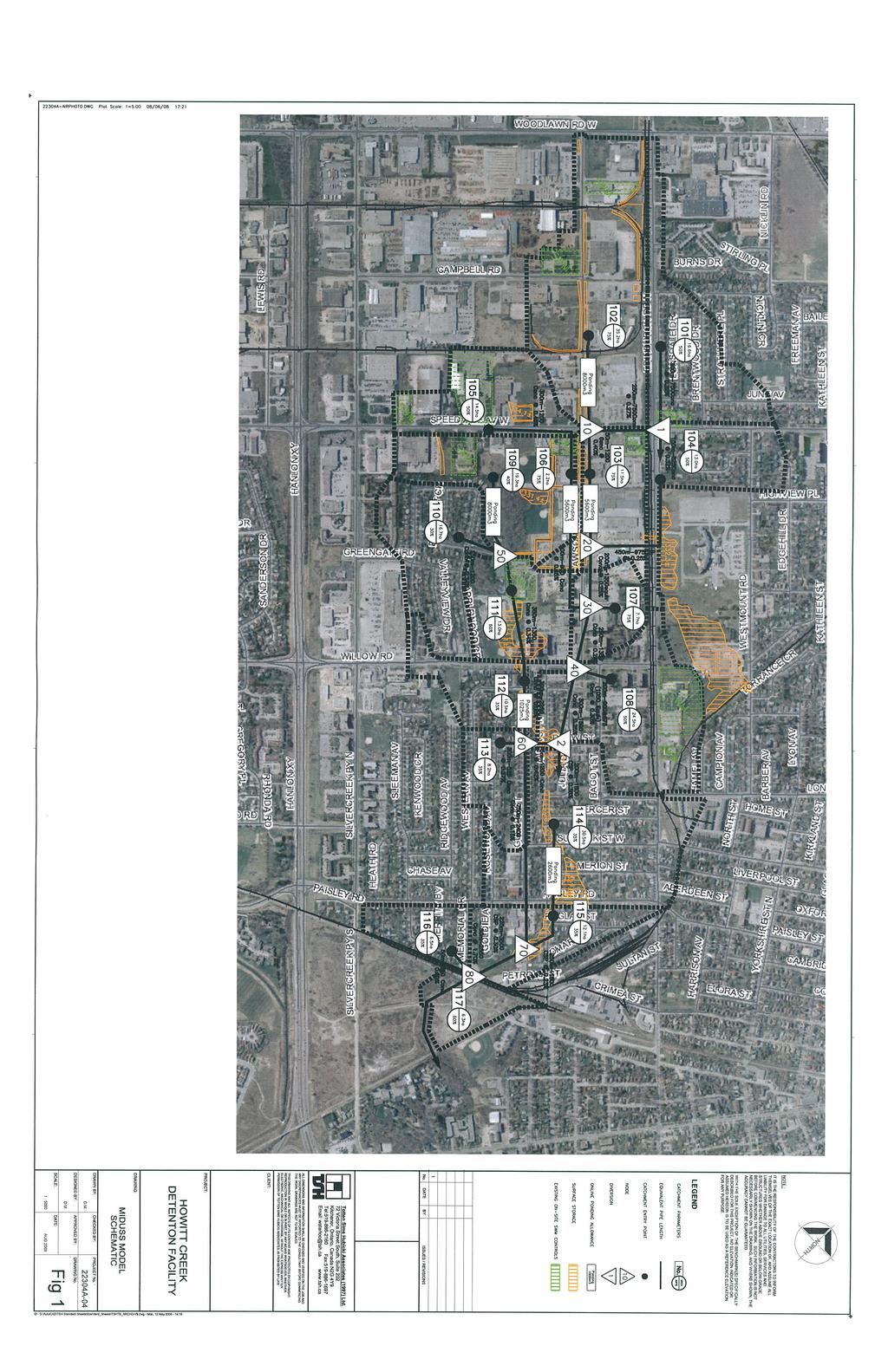
4 At the upper end of the drainage area, the ditches have sufficient depth to create a hydraulic head on the upper reaches of the storm sewer system. This hydraulic head, coupled with the runoff admitted to the system from the catchbasins would most likely be sufficient to produce a surcharge on the downstream storm sewers. The surcharge would result in flows greater than the full flow condition assumed in PVA s analysis. The OTTHYMO model in the CCL analysis used large subcatchments and did not include any piped flow components. The model was calibrated using relatively small rainfall events captured in the 1991 monitoring program. Through discussions with City Staff and the Developer, it was decided that an independent analysis of the upstream drainage area, using the MIDUSS model, would be prepared. 4.0 Stormwater Management Analysis 4.1 Watershed Analysis Using the available background information and a field reconnaissance tour, the upstream drainage area was defined to be 242.3ha. The drainage area upstream of the development was subdivided into 16 catchment areas using the topographic and storm sewer data. The developed part of the site will be designed to convey runoff to the Northwest Storm Drain and away from Howitt Creek, so this area was not included in the model. The existing creek valley and the lands east of the creek, where the proposed stormwater management facility is located, were added to the analysis so that the flow in Howitt Creek leaving the site could also be determined. Areas and approximate volumes of upstream ponding were identified using the topographic information and plan and profile drawings. These areas include the ditches on Dawson Road and ditches, pipe and surface ponding in Norm Jary Park and along Alma Street. MIDUSS modeling parameters, including area, impervious percentage, gradient and length were established for each of the subcatchment areas. The impervious percentage for subcatchments that included properties with known on-site stormwater management facilities was reduced to account for the on-site attenuation. Appendix A includes the design parameters used in the model for each subcatchment area. Figure 1 shows the catchment areas, properties that include on-site stormwater management facilities and areas of potential ponding used in the model. 4.2 Runoff Modeling City of Guelph standard rainfall parameters were used in the analysis and are summarized in Appendix A. Figure 1 includes the MIDUSS model schematic used in the analysis. A comprehensive model that includes all upstream storm sewers is beyond the required scope of this review, however, the model includes equivalent pipe sections to account for the conveyance through the storm sewer network, diversions where the piped flow capacity is exceeded and temporary storage of runoff in the areas described above. Flows from each subcatchment area were calculated and where appropriate, routed through the temporary ponding/storage areas and the piped network. Where the model predicted that the existing piped system would surcharge, the topographic and plan and profile drawings were reviewed to determine whether the amount of expected surcharge would be accommodated within the system. The resulting flows entering Howitt Creek from the Alma Relief Sewer are m 3 /s and m 3 /s for the 5 year and 100 year storms respectively. MIDUSS output files are included in Appendix C and model results on a reach by reach basis are summarized in the schematic drawing included in Appendix D. Page 3
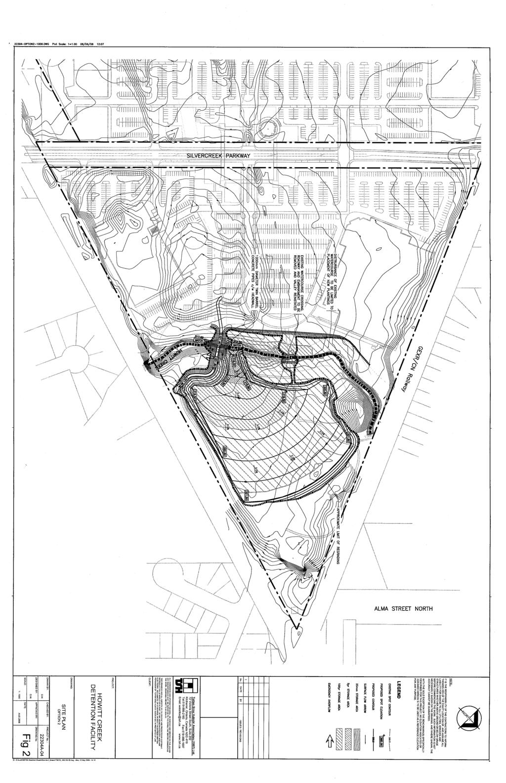
5 The model then routes this flow through the channel downstream of the railroad and adds in the flow from the eastern part of the development. The resulting flow to the proposed stormwater management facilty is m 3 /s and m 3 /s for the 5year and 100 year storms respectively. 4.3 Downstream Constraints Both the 1991 CCL study and the 1970 Kilborn study identified the culvert that carries Howitt Creek under Waterloo Avenue as the critical conveyance constraint. According to the 1970 report and as confirmed with drawings provided by the City, this structure is a concrete box with a width of 2.44m and a height of 2.13m. It is approximately 91m long and is constructed at a 2.2% grade. Using MTO Design Charts, we have calculated that the capacity of this structure is 13 m 3 /s with the upstream water level at the obvert of the culvert and 14.9 m 3 /s with a water level at the elevation of the top of the structure. The velocity of flow through the structure at this flow is very high (greater than 7 m/s). This confirms the capacity information provided in the previous studies. As indicated in the CCL report, the existing twin 1200mm diameter culverts on site do no have sufficient capacity to convey the flows from the Alma Relief Sewer. The capacity of these culverts will result in flooding upstream of the structures. As the water level rises upstream, some runoff is diverted to the Northwest Storm Drain and once the internal access road is overtopped, the remainder is conveyed downstream through Howitt Creek. The CCL report reported that the peak flow being conveyed downstream of the development is 16 m 3 /s and that the lands downstream of the development but upstream of Waterloo Avenue contribute an additional 3 m 3 /s. The resulting flow to the Waterloo Avenue culvert results in periodic flooding upstream of the structure. CCL recommended that the flow conveyed through the development be limited to 11m 3 /s to reduce the potential flooding impact. 4.4 SWM Facility Design In order to limit the Howitt Creek flows to suit the capacity of the Waterloo Avenue culvert, a stormwater management facility is proposed on the eastern part of the development site. Figure 2 shows the proposed stormwater management facility design. The existing twin 1200mm diameter culverts will be removed and a new twin 1200mm diameter crossing provided approximately 90m downstream of the current location. The lands east of the creek will be excavated to provide temporary storage of the upstream flows. The flow rate through the culvert is dependent on the water level upstream of the culvert. As the water level rises upstream of the new culverts, additional storage becomes available and there is an increased flow through the structure. A stage-storage-discharge chart for the facility was calculated and is provided in Appendix B. The resulting flood levels for the 25mm storm, 5 year and 100 year events are shown in Figure 2. Results of the modeling are summarized in Table 1. Table 1 Proposed Stormwater Management Facility Performance Design Storm 25mm 5 Year 100 Year Peak Inflow (m 3 /sec) Peak Outflow (m 3 /sec) Maximum Depth (m) Maximum Storage (m 3 ) 643 6,010 35,766 Maximum Elevation (m) Page 4
6 5.0 Conclusions The Alma Relief Sewer discharges at a maximum flow of m 3 /s to Howitt Creek at the upstream limit of the Silvercreek Junction development. There are no flows to Howitt Creek from the portion of the Silvercreek Junction site that is proposed for development. The existing detention storage located in ditches, pipes and surface storage within the upstream drainage area attenuates existing flows reaching the Silvercreek Junction site. Any future development or drainage improvements within the upstream lands must take into consideration the flow capacity of the downstream systems and implement additional stormwater management features as required. A stormwater management facility provided on the Silvercreek Junction site can control flows from the upstream lands to a level suitable for the downstream conveyance constraint at Waterloo Avenue. Peak flows being conveyed downstream of the development will be reduced from 16 m 3 /s to 10.8 m 3 /s. Provision of a stormwater management facility on the Silvercreek Junction site will remove a flow of approximately 10.5 m 3 /s from the Northwest Storm Drain. All of which is respectfully submitted; totten sims hubicki associates Rick Clement, P.Eng. Manager, Municipal Engineering Page 5
7
8
9
10
11
12
13
14
15
16
17
18
19
20
21
22
23
24
25
26
27
28
29
30
31
32
33
34
35
36
37
38
39
40
41
42
43
44
45
46
47
48
49
50
51
52
Storm Sewers, Page 2
 Storm Sewers storm sewer systems are dendritic systems used to collect and direct stormwater runoff storm sewer systems are integral components of any urban infrastructure curbs, gutters and storm inlets
Stormwater Management Report Bachman Terrace Residential Development
 Stormwater Management Report Bachman Terrace Residential Development Project # 160401069 Prepared for: Tega Developments Prepared by: Stantec Consulting Ltd. April 14, 2014 Sign-off Sheet This document
OHM Groups. FUNCTIONAL SERVICING REPORT 33 Arkell Road City of Guelph August 5, Prepared By:
 Prepared By: OHM Groups FUNCTIONAL SERVICING REPORT 33 Arkell Road City of Guelph 114169 August 5, 2015 Guelph Owen Sound Listowel Kitchener Exeter Hamilton GTA 650 Woodlawn Rd. W., Block C, Unit 2, Guelph
Drainage Servicing Report - Terms of Reference
 Urban Form and Corporate Strategic Development City Planning 7th Floor, Edmonton Tower 10111 104 Avenue NW Edmonton, AB T5J 0J4 edmonton.ca July 2018 1 Introduction: Drainage Servicing Reports Drainage
STORM DRAINAGE DESIGN MANUAL
 Appendix I STORM DRAINAGE DESIGN MANUAL by: SUNGATE DESIGN GROUP, P.A. GEN ERAL DESIGN STAN DARDS AN D POLICIES 1. STREET AND LOCAL DRAINAGE Discharge estimates for specified design storms shall be calculated
RETENTION BASIN EXAMPLE
 -7 Given: Total Tributary Area = 7.5 ac o Tributary Area within Existing R/W = 5.8 ac o Tributary Area, Impervious, Outside of R/W = 0.0 ac o Tributary Area, Pervious, Outside of R/W = 1.7 ac o Tributary
Storm Sewer Design - Introduction
 Class 4 [1] Storm Sewer Design - Introduction As urban drainage can not be expected to accommodate all rainfall events, the first step in the design procedure is to select an appropriate design storm.
PRELIMINARY DRAINAGE STUDY
 PRELIMINARY DRAINAGE STUDY For 34 th & J Residences 3402 J St. San Diego, CA 92102 A.P.N 545-250-08 Prepared By: Kenneth J. Discenza, P.E. Site Design Associates, Inc. 1016 Broadway, Suite A El Cajon,
3.3 Acceptable Downstream Conditions
 iswm TM Criteria Manual - = Not typically used or able to meet design criterion. 1 = The application and performance of proprietary commercial devices and systems must be provided by the manufacturer and
FLOOD PLAIN MANAGEMENT
 CITY OF STRATFORD STRATFORD WEST SECONDARY PLAN FLOOD PLAIN AND STORM WATER MANAGEMENT COURT DRAIN AND MCNAMARA DRAIN MCCORMICK RANKIN CORPORATION December 2007 TABLE OF CONTENTS 1.0 INTRODUCTION...2 1.1
APPENDIX E APPENDIX E ESTIMATING RUNOFF FOR SMALL WATERSHEDS
 APPENDIX E ESTIMATING RUNOFF FOR SMALL WATERSHEDS March 18, 2003 This page left blank intentionally. March 18, 2003 TABLES Table E.1 Table E.2 Return Frequencies for Roadway Drainage Design Rational Method
Functional Servicing Report. Winston Park West Proposed Business Park Development Project. Infrastructure Ontario (IO) September MU1
 September MU1") Functional Servicing Report Winston Park West Proposed Business Park Development Project (IO) September 2011 14-11208-001-MU1 Winston Park West 2 TABLE OF CONTENTS Page 1.0 INTRODUCTION... 3 1.1 SITE DESCRIPTION...
Functional Servicing Report Winston Park West Proposed Business Park Development Project (IO) September 2011 14-11208-001-MU1 Winston Park West 2 TABLE OF CONTENTS Page 1.0 INTRODUCTION... 3 1.1 SITE DESCRIPTION...
A Stormwater Management Plan and Sediment Control Plan are required for all proposed developments within the City of Richmond.
 Engineering Page 3-1 3.0 STORM DRAINAGE 3.1 GENERAL Good drainage is vital to flat urban areas such as Lulu Island. It is essential that every storm sewer must be designed accurately minimizing conflicts
Chapter 4. Drainage Report and Construction Drawing Submittal Requirements
 4.0 Introduction The requirements presented in this section shall be used to aid the design engineer or applicant in the preparation of drainage reports, drainage studies, and construction drawings for
Using Sanitary Sewer I/I Field Data to Calibrate a Storm Sewer Model
 15 Using Sanitary Sewer I/I Field Data to Calibrate a Storm Sewer Model Josh A. Reinicke, Marc A. Lehmann and C. Timothy Fallara Since 1992, the City of Columbus Division of Sewerage and Drainage (DOSD)
Chapter 6. Hydrology. 6.0 Introduction. 6.1 Design Rainfall
 6.0 Introduction This chapter summarizes methodology for determining rainfall and runoff information for the design of stormwater management facilities in the City. The methodology is based on the procedures
Jacobi, Toombs, and Lanz, Inc.
 Area 5: Blackiston Mill Road at Dead Man's Hollow Flooding Assessment Jacobi, Toombs, and Lanz, Inc. This document summarizes an assessment of drainage and flooding concerns and provides recommendations
STORMWATER MANAGEMENT REPORT DRAFT PLAN OF CITY OF GUELPH
 Debrob Investments Limited STORMWATER MANAGEMENT REPORT DRAFT PLAN OF SUBDIVISION, CITYVIEW DRIVE CITY OF GUELPH PRELIMINARY NOVEMBER 2, 2011 I B I G R O U P P R E L I M I N A R Y Debrob Investments Limited
CRYSTAL LAKE FLOODING STUDY EXECUTIVE SUMMARY
 Project #08223 CRYSTAL LAKE FLOODING STUDY EXECUTIVE SUMMARY PREPARED FOR: City of Crystal Lake 100 West Woodstock Street Crystal Lake, Illinois 60014 FEBRUARY 11, 2009 26575 W. COMMERCE DRIVE, SUITE 601,
APPENDIX E Drainage and Stormwater Management Report
 APPENDIX E Drainage and Stormwater Management Report Drainage and Stormwater Management Report Courtneypark Drive East Class EA & Preliminary Design Prepared for: City of Mississauga Prepared by: Stantec
Action plans for hotspot locations
 Action plans for hotspot locations Ash Vale North 1. Local evidence indicates the culvert could not discharge during December 2013 because the outlet was blocked on the western side of the railway. Guildford
III. INVENTORY OF EXISTING FACILITIES
 III. INVENTORY OF EXISTING FACILITIES Within the Growth Management Boundary, the existing storm drainage facilities are largely associated with development that has historically occurred in the ten drainage
Public Works and Engineering
 6.C Exhibit Incorporated in 1909 Public Works and Engineering Committee Report To: From: Mayor and Board of Trustees Bill Emmerich For Village Board Meeting of: November 27, 2017 Subject: Division and
E. STORMWATER MANAGEMENT
 E. STORMWATER MANAGEMENT 1. Existing Conditions The Project Site is located within the Lower Hudson Watershed. According to the New York State Department of Environmental Conservation (NYSDEC), Lower Hudson
TABLE OF CONTENTS PART III - MINIMUM DESIGN STANDARDS Section 105 DRAINAGE SYSTEM DESIGN SPECIFICATIONS AND SCOPE 105.1
 TABLE OF CONTENTS PART III - MINIMUM DESIGN STANDARDS Section 105 DRAINAGE SYSTEM DESIGN SECTION TITLE PAGE 105.1. SPECIFICATIONS AND SCOPE 105.1 105.2. METHODS OF ANALYSIS 105.1 105.2.1. Rational Method
APPENDIX E ESTIMATING RUNOFF FROM SMALL WATERSHEDS
 ESTIMATING RUNOFF FROM SMALL WATERSHEDS June 2011 THIS PAGE LEFT BLANK INTENTIONALLY. June 2011 TABLES Table E.1 Table E.2 Return Frequencies for Roadway Drainage Design Rational Method Values June 2011
Report. Inflow Design Flood Control System Plan St. Clair Power Plant St. Clair, Michigan. DTE Energy Company One Energy Plaza, Detroit, MI
 Report Inflow Design Flood Control System Plan St. Clair Power Plant St. Clair, Michigan DTE Energy Company One Energy Plaza, Detroit, MI October 14, 2016 NTH Project No. 62-160047-04 NTH Consultants,
INFLOW DESIGN FLOOD CONTROL SYSTEM PLAN 40 C.F.R. Part PLANT MCINTOSH ASH POND 1 GEORGIA POWER COMPANY
 INFLOW DESIGN FLOOD CONTROL SYSTEM PLAN 40 C.F.R. Part 257.82 PLANT MCINTOSH ASH POND 1 GEORGIA POWER COMPANY EPA s Disposal of Coal Combustion Residuals from Electric Utilities Final Rule (40 C.F.R. Part
Appendix G Preliminary Hydrology Study
 Appendix G Preliminary Hydrology Study Preliminary Hydrology Study VESTING TTM 72608 Long Beach, CA Prepared for: The Long Beach Project, LLC 888 San Clemente, Suite 100 New Port Beach, CA May 28, 2014
INITIAL INFLOW DESIGN FLOOD CONTROL SYSTEM PLAN PLANT MCMANUS ASH POND A (AP-1) 40 CFR
 40 CFR") INITIAL INFLOW DESIGN FLOOD CONTROL SYSTEM PLAN PLANT MCMANUS ASH POND A (AP-1) 40 CFR 257.82 EPA s Disposal of Coal Combustion Residuals from Electric Utilities Final Rule (40 C.F.R. Part 257 and Part
INITIAL INFLOW DESIGN FLOOD CONTROL SYSTEM PLAN PLANT MCMANUS ASH POND A (AP-1) 40 CFR 257.82 EPA s Disposal of Coal Combustion Residuals from Electric Utilities Final Rule (40 C.F.R. Part 257 and Part
CONSTRUCTION PLAN CHECKLIST
 CONSTRUCTION PLAN CHECKLIST The design engineer is responsible for ensuring that plans submitted for city review are in accordance with this checklist. It is requested that the executed checklist be submitted
JOHNSTON ROAD LAND USE STUDY
 JOHNSTON ROAD LAND USE STUDY SERVICING FEASIBILITY STUDY Project No. 2814 Prepared for: City of Ottawa Planning Branch Infrastructure Approvals Branch Prepared by: David McManus Engineering Ltd. 400 30
FUNCTIONAL SERVICING AND STORMWATER MANAGEMENT STUDY 405 TWEEDSMUIR AVENUE
 FUNCTIONAL SERVICING AND STORMWATER MANAGEMENT STUDY FOR CITY OF OTTAWA PROJECT NO.: 11-532 FOR TABLE OF CONTENTS 1.0 INTRODUCTION... 1 1.1 Existing Conditions... 2 1.2 Required Permits / Approvals...
Contents. Drainage Analysis: Hunters Trace, Westpointe, and Hunters Creek
 Drainage Analysis: Hunters Trace, Westpointe, and Hunters Creek Contents SITE LOCATION / DESCRIPTION... 3 WESTPOINTE STORMWATER MANAGEMENT PLAN... 3 THE ENCLAVE AT WESTPOINTE DETENTION POND... 3 Table
Introduction to Storm Sewer Design
 A SunCam online continuing education course Introduction to Storm Sewer Design by David F. Carter Introduction Storm sewer systems are vital in collection and conveyance of stormwater from the upstream
STORM DRAINS AND IRRIGATION
 TABLE OF CONTENTS PART III - MINIMUM DESIGN STANDARDS Section 105 STORM DRAINS AND IRRIGATION 105.1. STORM DRAINS... 105.1 105.2. METHODS OF ANALYSIS... 105.1 105.2.1. Rational Method... 105.1 105.2.2.
APPENDIX D. Drainage and Stormwater Management Assessment Memoranda
 APPENDIX D Drainage and Stormwater Management Assessment Memoranda 610 Chartwell Road, Suite 300 Oakville, Ontario, L6J 4A9 Tel: (905) 823-8500 Fax: (905) 823-8503 Website: www.wspgroup.ca TECHNICAL MEMORANDUM
INFLOW DESIGN FLOOD CONTROL SYSTEM PLAN 40 C.F.R. PART PLANT BOWEN ASH POND 1 (AP-1) GEORGIA POWER COMPANY
 GEORGIA POWER COMPANY") INFLOW DESIGN FLOOD CONTROL SYSTEM PLAN 40 C.F.R. PART 257.82 PLANT BOWEN ASH POND 1 (AP-1) GEORGIA POWER COMPANY EPA s Disposal of Coal Combustion Residuals from Electric Utilities Final Rule (40 C.F.R.
INFLOW DESIGN FLOOD CONTROL SYSTEM PLAN 40 C.F.R. PART 257.82 PLANT BOWEN ASH POND 1 (AP-1) GEORGIA POWER COMPANY EPA s Disposal of Coal Combustion Residuals from Electric Utilities Final Rule (40 C.F.R.
APPENDIX F: DRAINAGE AND STORMWATER MANAGEMENT
 APPENDIX F: DRAINAGE AND STORMWATER MANAGEMENT Downtown Ottawa Transit Tunnel: Tunney s Pasture to Blair Station via a Downtown LRT Tunnel Prepared for: City of Ottawa 110 Laurier Avenue West Ottawa, ON
SECTION STORM DRAINAGE DESIGN, GRADING, AND WATER QUALITY TECHNICAL CRITERIA TABLE OF CONTENTS PAGE 402 STORM DRAINAGE DESIGN CRITERIA 400-1
 CITY OF THORNTON Standards and Specifications Revised: October 2012 SECTION 400 - STORM DRAINAGE DESIGN, GRADING, AND WATER QUALITY TECHNICAL CRITERIA TABLE OF CONTENTS PAGE 401 GENERAL PROVISIONS 400-1
DRAINAGE REVIEW: Berwick Health and Education Precinct. for. Victorian Planning Authority
 DRAINAGE REVIEW: Berwick Health and Education Precinct for Victorian Planning Authority April 2017 Document history Revision: Revision no. 03 Author/s Jonathon McLean Approved Jonathon McLean Distribution:
Report. Inflow Design Flood Control System Plan Belle River Power Plant East China, Michigan. DTE Energy Company One Energy Plaza, Detroit, MI
 Report Inflow Design Flood Control System Plan Belle River Power Plant East China, Michigan DTE Energy Company One Energy Plaza, Detroit, MI October 14, 2016 NTH Project No. 62-160047-04 NTH Consultants,
COOPER STREET, EPPING STORMWATER MANAGEMENT STRATEGY. May Cooper Street Pty Ltd
 415-425 COOPER STREET, EPPING STORMWATER MANAGEMENT STRATEGY May 2017 Cooper Street Pty Ltd Disclaimer Dalton Consulting Engineers Pty Ltd This report has been prepared solely for the benefit of Cooper
Planning Considerations for Stormwater Management in Alberta. R. D. (Rick) Carnduff, M. Eng., P. Eng. February 20, 2013.
 Carnduff, M. Eng., P. Eng. February 20, 2013.") Planning Considerations for Stormwater Management in Alberta R. D. (Rick) Carnduff, M. Eng., P. Eng. February 20, 2013 Photo Optional Purpose The purpose of urban stormwater management is to provide solutions
Planning Considerations for Stormwater Management in Alberta R. D. (Rick) Carnduff, M. Eng., P. Eng. February 20, 2013 Photo Optional Purpose The purpose of urban stormwater management is to provide solutions
HYDROLOGIC-HYDRAULIC STUDY ISABELLA OCEAN RESIDENCES ISLA VERDE, CAROLINA, PR
 HYDROLOGIC-HYDRAULIC STUDY ISABELLA OCEAN RESIDENCES ISLA VERDE, CAROLINA, PR 1 INTRODUCTION 1.1 Project Description and Location Isabella Ocean Residences is a residential development to be constructed
INFLOW DESIGN FLOOD CONTROL SYSTEM PLAN PLANT GREENE COUNTY ASH POND ALABMA POWER COMPANY
 INFLOW DESIGN FLOOD CONTROL SYSTEM PLAN PLANT GREENE COUNTY ASH POND ALABMA POWER COMPANY Section 257.82 of EPA s regulations requires the owner or operator of an existing or new CCR surface impoundment
HY-12 User Manual. Aquaveo. Contents
 Y-12 User Manual Aquaveo Contents Overview...2 Watershed Parameters...3 Channel Parameters...3 Storm Drain Parameters...3 Design of new systems...4 Analysis of existing systems...4 Steady flow...4 ydrographic
FORT COLLINS STORMWATER CRITERIA MANUAL Hydrology Standards (Ch. 5) 1.0 Overview
 1.0 Overview") Chapter 5: Hydrology Standards Contents 1.0 Overview... 1 1.1 Storm Runoff Determination... 1 1.2 Design Storm Frequencies... 1 1.3 Water Quality Storm Provisions... 2 1.4 Design Storm Return Periods...
Chapter 5: Hydrology Standards Contents 1.0 Overview... 1 1.1 Storm Runoff Determination... 1 1.2 Design Storm Frequencies... 1 1.3 Water Quality Storm Provisions... 2 1.4 Design Storm Return Periods...
Environmental Assessment Derry Road and Argentia Road Intersection
 Environmental Assessment Derry Road and Argentia Road Intersection Project 11-4295 City of Mississauga, Region of Peel October 15, 2014 INTRODUCTION Table of Contents Introduction... 2 Description of the
Project Drainage Report
 Design Manual Chapter 2 - Stormwater 2A - General Information 2A-4 Project Drainage Report A. Purpose The purpose of the project drainage report is to identify and propose specific solutions to stormwater
Drainage Report. New Braunfels Municipal Airport. Master Plan Update 2005
 Drainage Report Master Plan Update 2005 General The Texas Department of Transportation (TxDOT), Aviation Division, retained the consulting engineering team of Parkhill, Smith & Cooper, Inc. (PSC), to prepare
Stormwater Local Design Manual For Houston County, Georgia
 Stormwater Local Design Manual For Houston County, Georgia Adopted November 15, 2005 TABLE OF CONTENTS 1. FORWARD... 1 2. GENERAL LEVEL OF SERVICE STANDARDS... 2 2.1. DETENTION REQUIREMENTS... 2 2.1.1.
Stantec Consulting Ltd Hagey Boulevard, Waterloo ON N2L 0A4
 Stantec Consulting Ltd. 100-300 Hagey Boulevard, Waterloo ON N2L 0A4 November 17, 2017 File: 1614-13551/29 Attention: Ms. Nancy Shoemaker Black, Shoemaker, Robinson and Donaldson Ltd. Surveyors 351 Speedvale
DRAINAGE & DESIGN OF DRAINAGE SYSTEM
 Drainage on Highways DRAINAGE & DESIGN OF DRAINAGE SYSTEM P. R.D. Fernando Chartered Engineer B.Sc.(Hons), M.Eng. C.Eng., MIE(SL) Drainage Requirement of Highway Drainage System Introduction Drainage means
Section H - Site Plan Guidelines
 H1 GENERAL REQUIREMENTS The following is an outline of procedures and requirements for preparation and submission of Grading Plans, Site Alteration Plans (Erosion and Sediment Control Plans), Site Servicing
INFLOW DESIGN FLOOD CONTROL SYSTEM PLAN 40 C.F.R. PART PLANT YATES ASH POND 3 (AP-3) GEORGIA POWER COMPANY
 GEORGIA POWER COMPANY") INFLOW DESIGN FLOOD CONTROL SYSTEM PLAN 40 C.F.R. PART 257.82 PLANT YATES ASH POND 3 (AP-3) GEORGIA POWER COMPANY EPA s Disposal of Coal Combustion Residuals from Electric Utilities Final Rule (40 C.F.R.
INFLOW DESIGN FLOOD CONTROL SYSTEM PLAN 40 C.F.R. PART 257.82 PLANT YATES ASH POND 3 (AP-3) GEORGIA POWER COMPANY EPA s Disposal of Coal Combustion Residuals from Electric Utilities Final Rule (40 C.F.R.
MODEL Stormwater Local Design Manual. City of Centerville
 MODEL Stormwater Local Design Manual City of Centerville Adopted December 6, 2005 TABLE OF CONTENTS 1. FORWARD... 1 2. GENERAL LEVEL OF SERVICE STANDARDS... 1 2.1. DETENTION REQUIREMENTS... 1 2.1.1. Discharge
APPENDIX F DRAINAGE AND STORMWATER MANAGEMENT TECHNICAL MEMO
 APPENDIX F DRAINAGE AND STORMWATER MANAGEMENT TECHNICAL MEMO MEMO To: Emily Sangster Date: April 28, 2015 From: Bhavika Patel Job No.: 34-14015-000-B02 Subject: Stormwater Management Impact Assessment
Learning objectives. Upon successful completion of this lecture, the participants will be able to describe:
 Solomon Seyoum Learning objectives Upon successful completion of this lecture, the participants will be able to describe: The different approaches for estimating peak runoff for urban drainage network
Water Resources Management Plan
 P L Y M O U T H M I N N E S O T A Appendix D: The developed a to analyze and minimize the impact of existing and future development on the City s natural resources. It is important to the City to have
INITIAL RUN-ON AND RUN-OFF CONTROL PLAN 40 C.F.R. PART 257
 INITIAL RUN-ON AND RUN-OFF CONTROL PLAN 40 C.F.R. PART 257.81 HUFFAKER ROAD (PLANT HAMMOND) PRIVATE INDUSTRIAL LANDFILL (HUFFAKER ROAD LANDFILL) GEORGIA POWER COMPANY EPA s Disposal of Coal Combustion
Longfields Subdivision, Block 7, City of Ottawa
 Longfields Subdivision, Block 7, City of Ottawa 160400850/160401231 Prepared for: Campanale Homes Prepared by: Stantec Consulting Ltd. Table of Contents 1.0 INTRODUCTION...1.1 2.0 BACKGROUND...2.2 3.0
Dawson County Public Works 25 Justice Way, Suite 2232, Dawsonville, GA (706) x 42228
 x 42228") Dawson County Public Works 25 Justice Way, Suite 2232, Dawsonville, GA 30534 (706) 344-3500 x 42228 DAWSON COUNTY STORM WATER REVIEW CHECKLIST Project Name: Property Address: Engineer: Fax #/Email: Date:
Dawson County Public Works 25 Justice Way, Suite 2232, Dawsonville, GA 30534 (706) 344-3500 x 42228 DAWSON COUNTY STORM WATER REVIEW CHECKLIST Project Name: Property Address: Engineer: Fax #/Email: Date:
Appendix H Amanda Estates Drainage Study
 Appendix H Amanda Estates Drainage Study Hunsaker & Associates 2015 Contents 1 Scope... 1 2 Existing Conditions... 1 3 Project Description... 3 4 Methodology... 5 4.1 Hydrology... 5 4.2 Hydraulics...
Warner Robins Stormwater Local Design Manual
 Warner Robins Stormwater Local Design Manual Prepared for Houston County City of Warner Robins City of Perry City of Centerville May 17, 2005 Version 4 (As presented with adopted Stormwater Ordinance)
Hydrology Study. Ascension Heights Subdivision Ascension Drive at Bel Aire Road San Mateo, California (Unincorporated)
") Hydrology Study Ascension Heights Subdivision Ascension Drive at Bel Aire Road San Mateo, California (Unincorporated) Prepared for San Mateo Real Estate & Construction March 9, 21 Rev. 1 11-8-211 Rev.
Hydrology Study Ascension Heights Subdivision Ascension Drive at Bel Aire Road San Mateo, California (Unincorporated) Prepared for San Mateo Real Estate & Construction March 9, 21 Rev. 1 11-8-211 Rev.
3.0 Planning and Submittal Requirements
 October 2003, Revised February 2005 Chapter 3.0, Planning and Submittal Requirements Page 1 3.0 Planning and Submittal Requirements 3.1 Drainage Studies and Drawings The City of Greenwood Village (Village)
NEW CASTLE CONSERVATION DISTRICT. through. (Name of Municipality) PLAN REVIEW APPLICATION DRAINAGE, STORMWATER MANAGEMENT, EROSION & SEDIMENT CONTROL
 PLAN REVIEW APPLICATION DRAINAGE, STORMWATER MANAGEMENT, EROSION & SEDIMENT CONTROL") NEW CASTLE CONSERVATION DISTRICT through (Name of Municipality) PLAN REVIEW APPLICATION DRAINAGE, STORMWATER MANAGEMENT, EROSION & SEDIMENT CONTROL Office use only: Received by Municipality: Received by
NEW CASTLE CONSERVATION DISTRICT through (Name of Municipality) PLAN REVIEW APPLICATION DRAINAGE, STORMWATER MANAGEMENT, EROSION & SEDIMENT CONTROL Office use only: Received by Municipality: Received by
Storm water Catchment Analysis
 Storm water Catchment Analysis Analysis index 1. Storm water attenuation tank sizing method 2. Consent notices for storm water attenuation tanks 3. Summary of sub catchments 4. Hydrological Analysis for
ZONING ORDINANCE FOR THE ZONED UNINCORPORATED AREAS ARTICLE 1500 OF PUTNAM COUNTY, WEST VIRGINIA Page 149 ARTICLE 1500 DRAINAGE AND STORM SEWERS
 OF PUTNAM COUNTY, WEST VIRGINIA Page 149 ARTICLE 1500 DRAINAGE AND STORM SEWERS 1500.01 GENERAL REQUIREMENTS 1500.02 NATURE OF STORM WATER FACILITIES 1500.03 DRAINAGE EASEMENTS 1500.04 STORM WATER MANAGEMENT
THE STUDY ON INTEGRATED URBAN DRAINAGE IMPROVEMENT FOR MELAKA AND SUNGAI PETANI IN MALAYSIA FINAL REPORT
 THE GOVERNMENT OF MALAYSIA PRIME MINISTER S DEPARTMENT ECONOMIC PLANNING UNIT THE STUDY ON INTEGRATED URBAN DRAINAGE IMPROVEMENT FOR MELAKA AND SUNGAI PETANI IN MALAYSIA FINAL REPORT VOL. 5: TECHNICAL
LAKE COUNTY HYDROLOGY DESIGN STANDARDS
 LAKE COUNTY HYDROLOGY DESIGN STANDARDS Lake County Department of Public Works Water Resources Division 255 N. Forbes Street Lakeport, CA 95453 (707)263-2341 Adopted June 22, 1999 These Standards provide
Design Specifications & Requirements Manual
 9 GRADING 9.1 GRADING REQUIREMENTS FOR VARIOUS SITUATIONS... 1 9.1.1 Subdivisions... 1 9.1.2 Site Plans... 1 9.1.3. Severances, Lifting of Part Lot Control & Infill Lots... 1 9.1.4 Blocks... 1 9.1.5 Capital
CUYAHOGA COUNTY ENGINEER
 CUYAHOGA COUNTY ENGINEER DRAINAGE MANUAL Supplement to O.D.O.T. LOCATION and DESIGN MANUAL, Volume 2, Drainage Design, Section 1000 and 1100 May 28, 2010 Revisions to the July 29, 2009 edition are noted
DICKINSON BAYOU WATERSHED STEERING COMMITTEE FINAL MEMBER CRITERIA COMPARISON
 DICKINSON BAYOU WATERSHED STEERING COMMITTEE FINAL MEMBER CRITERIA COMPARISON May 25, 2006 INTRODUCTION The Dickinson Bayou Watershed covers approximately 95.5 square miles and stretches from western Brazoria
LDS Technical Guidance
 May 21, 2008 The following was provided to County staff as internal guidance for reviewers in applying the adequate outfall requirements of the Public Facilities Manual (PFM). A number of private sector
Stormwater Erosion Control & Post-Construction Plans (Stormwater Quality Plans)
") Stormwater Erosion Control & Post-Construction Plans (Stormwater Quality Plans) Allen County Stormwater Plan Submittal Checklist The following items must be provided when applying for an Allen County Stormwater
Stormwater Erosion Control & Post-Construction Plans (Stormwater Quality Plans) Allen County Stormwater Plan Submittal Checklist The following items must be provided when applying for an Allen County Stormwater
Considerations In Estimating Tailwater Elevations
 Considerations In Estimating Tailwater Elevations by Alphonse (Al) J. Stewart, P.E., President www.suncam.com Page 1 of 39 ************************************************************************ This
6.0 SURFACE WATER MANAGEMENT STRATEGY
 6.0 SURFACE WATER MANAGEMENT STRATEGY The Surface Water Management Strategy comprises three main parts: Carp River Floodplain management; overland flow/cross drainage features; and, Shirley s Brook Realignment.
PROPOSED THREE-STOREY RESIDENTIAL APARTMENT BUILDING SITE LOT 19 R-PLAN ROCKINGHAM AVENUE CITY OF OTTAWA STORM DRAINAGE REPORT
 PROPOSED THREE-STOREY RESIDENTIAL APARTMENT BUILDING SITE LOT 19 R-PLAN 149 1162 ROCKINGHAM AVENUE CITY OF OTTAWA STORM DRAINAGE REPORT REPORT No. R-815-41 T. L. MAK ENGINEERING CONSULTANTS LTD. JUNE 2015
215 Sanders Street, Unit 1 (613) Prescott Street, Unit 1 P.O. Box 189 Kemptville, Ontario K0G 1J0 FAX: (613)
 Prescott Street, Unit 1 P.O. Box 189 Kemptville, Ontario K0G 1J0 FAX: (613)") Civil Geotechnical Structural Environmental 215 Sanders Street, Unit 1 (613) 860-0923 210 Prescott Street, Unit 1 P.O. Box 189 Kemptville, Ontario K0G 1J0 FAX: (613) 258-0475 March 29, 2016 2343065 Ontario
Civil Geotechnical Structural Environmental 215 Sanders Street, Unit 1 (613) 860-0923 210 Prescott Street, Unit 1 P.O. Box 189 Kemptville, Ontario K0G 1J0 FAX: (613) 258-0475 March 29, 2016 2343065 Ontario
Learn how to design inlet grates, detention basins, channels, and riprap using the FHWA Hydraulic Toolbox and WMS
 v. 11.0 WMS 11.0 Tutorial Learn how to design inlet grates, detention basins, channels, and riprap using the FHWA Hydraulic Toolbox and WMS Objectives Learn how to use several Hydraulic Toolbox calculators
SECTION 4 STORM DRAINAGE
 4.01 GENERAL SECTION 4 STORM DRAINAGE These standards shall provide minimum requirements for the design of Storm Drainage and related appurtenances within the City of West Sacramento rights of way and
STORMWATER DRAINAGE ASSESSMENT. 479 Line 1 Road, Niagara-on-the-Lake, Ontario
 STORMWATER DRAINAGE ASSESSMENT 479 Line 1 Road, Niagara-on-the-Lake, Ontario November, 2015 1. Site Description Size: Location: Existing Land Use: Proposed Land Use: Soils: Stormwater Outlet: 1.38 hectares
DRAINAGE REPORT. Project Name: PG&E Gas Operations Technical Training Center Winters, CA. Date: February 4, Prepared by: BKF Engineers
 DRAINAGE REPORT Project Name: PG&E Gas Operations Technical Training Center Winters, CA Date: February 4, 2015 Prepared by: BKF Engineers Client: Pacific Gas & Electric Company This report has been prepared
Preliminary Drainage Analysis
 Preliminary Drainage Analysis Tanimura and Antle Employee Housing Town of Spreckels County of Monterey, California LIB150205 May 29, 2015 Prepared For: Tanimura and Antle Produce Prepared By: 9699 Blue
New Retirement Home 6758 & 6766 Rocque Street Orleans, Ontario
 New Retirement Home 6758 & 6766 Rocque Street Orleans, Ontario Site Servicing and Stormwater Management Report By Mohamad Salame, P.Eng. Kamco Technique Ltee. 60 Grand Avenue North Cambridge, Ontario N1S
Biggars Lane Landfill Expansion Environmental Assessment Stormwater Management Assessment County of Brant
 R.J. Burnside & Associates Limited 17345 Leslie Street, Suite 200 Newmarket ON L3Y 0A4 CANADA telephone (905) 953-8967 fax (905) 953-8945 web www.rjburnside.com Technical Memorandum Date: Project Name:
VILLAGE OF DEERFIELD Site Grading and Drainage Ordinance User Guide
 June 15, 2009 PURPOSE This has been prepared to assist in the uniform interpretation of the subject ordinance. These requirements and procedures establish a basis for the Village to utilize in the administration
2. DEFINITIONS. American Association of State Highway and Transportation Officials.
 2. DEFINITIONS 2.010 Definitions [See Amendment 2] In addition to words and terms that may be defined elsewhere in this manual, the following words and terms shall have the meanings defined below: AASHTO:
Debrob Investments Limited FUNCTIONAL SERVICING REPORT DRAFT PLAN OF SUBDIVISION, CITYVIEW DRIVE CITY OF GUELPH
 JULY 2013 DOCUMENT CONTROL Client: Project Name: Report Title: IBI Reference: 25528 Cityview Drive Version: JULY 2013 Digital Master: Originator: Reviewer: Authorization: [File Location] Scott MacDonald,
APPENDIX C. Storm Sewer Memo
 APPENDIX C Storm Sewer Memo TECHNICAL MEMORANDUM TO: Mr. Inderjit Hans MTE FILE NO.: C-42054-100 COMPANY: City of Bampton DATE: August 22, 2017 CC: Mr. Dave Hallman / Mr. Vince Pugliese, FROM: Jeremy MacCulloch
CHECKLIST FOR STREETS, INLETS, AND STORM SEWER DESIGN
 CHECKLIST FOR STREETS, INLETS, I. STREET CLASSIFICATION AND DESIGN CRITERIA A. Determine drainage classification for the roadway section using Table 7-1 or Table 7-2. B. Determine the allowable flow depth
Section 6: Stormwater Improvements
 Section 6: Stormwater Improvements A major objective of this study was to identify opportunities for improvements to address the widespread water quality impairments caused by stormwater runoff in the
EROSION AND SEDIMENT CONTROL STANDARDS CITY OF OVERLAND PARK DRAFT
 A. Authority EROSION AND SEDIMENT CONTROL STANDARDS CITY OF OVERLAND PARK DRAFT 06.15.2005 As set forth in the Overland Park Municipal Code (OPMC), Chapter 16.200, the Director of Planning and Development
Dunpar Developments Inc.
 Dunpar Developments Inc. Proposed Townhouse Development 2158, 2168, 2180 and 2192 Trafalgar Road Oakville, Ontario Functional Servicing and Stormwater Management Report (in Support of a Re-Zoning and Site
Detention Pond Design Considering Varying Design Storms. Receiving Water Effects of Water Pollutant Discharges
 Detention Pond Design Considering Varying Design Storms Land Development Results in Increased Peak Flow Rates and Runoff Volumes Developed area Robert Pitt Department of Civil, Construction and Environmental
MODULE 1 RUNOFF HYDROGRAPHS WORKSHEET 1. Precipitation
 Watershed MODULE 1 RUNOFF HYDROGRAPHS WORKSHEET 1 A watershed is an area of land thaaptures rainfall and other precipitation and funnels it to a lake or stream or wetland. The area within the watershed
Drainage Analysis. Appendix E
 Drainage Analysis Appendix E The existing and proposed storm drainage systems have been modeled with Bentley CivilStorm V8 computer modeling software. The peak stormwater discharge was determined for
INITIAL RUN-ON AND RUN-OFF CONTROL PLAN 40 C.F.R. PART 257
 INITIAL RUN-ON AND RUN-OFF CONTROL PLAN 40 C.F.R. PART 257.81 PLANT BOWEN PRIVATE INDUSTRY SOLID WASTE DISPOSAL FACILITY (ASH LANDFILL) GEORGIA POWER COMPANY EPA s Disposal of Coal Combustion Residuals