Water supply components
|
|
|
- Tyler Hensley
- 6 years ago
- Views:
Transcription
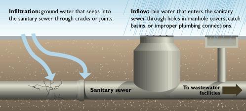
1 Water supply components Water sources structures (Dams, wells, reservoirs) Surface water Groundewater Pipelines from source Water treatment plant components Pumping stations Storage (elevated tanks) Distribution System Sources (components) of wastewater flow Domestic: discharges from residential, commercial, and institutional facilities. Industrial: discharges from different industries. Infiltration: groundwater seepage that enters sanitary sewer through cracks in pipe joints and manholes. Inflow: water that enters through drains which is relatively unpolluted source of water. Storm water: runoff from rain. Preliminary studies for water supply projects: The main factors required to be studied to supply a city with water system are: - Sources of water available - Quantity of water - Population (present and future) - Water consumption (present and future) - Design Period (30 50 years) 1
2 Quantity of Water The quantity of water to be supplied to any community depends on: - The population - The per capita consumption of water Water supply works must to be designed to serve the present population as well as the future population In the design of water works, it is necessary to estimate the quantity of water needed in the future (water demand). - The number of people that will be served at the end of the design period - The consumption rate o Average daily consumption in a community (m 3 /day) = Total water use in one year /365 days o Per capita average daily consumption: the amount of water used by individual per day, Lpcd = Avg. daily consumption in a community (Lpd) /mid year population - Analysis of factors affecting water consumption (e.g. climate, economic level, population density, quality of water, etc.) Population Estimation (forecast / projection) - Population project periods may range from 5 to 50 years depending on the particular component of the system that is being designed (e.g. distribution system, treatment plant, pumping stations, etc.) - Estimation of population depends on many factors such as: o Past census records (Bureau of census) o Economic conditions o Future growth of the economical and industrial activities in the region 2
3 - The rate of population growth can be expressed as a percent increase per year (e.g. 1.7% per year) (e.g. 17 people per year per 1000 population) - Factors affect rate of increase of population o Natural growth (birth and deaths) o Immigration o Diseases o Economic development o Health care A typical population growth curve has three segments: a geometric increase (exponential), an arithmetic increase and a decreasing rate of increase. 3
4 4
5 Example A community with a population of 22,000 has an average consumption of 600 Lpcd and a fire flow dictated by a building of ordinary construction with a floor area of 1000 m 2 and a height of 6 stories. Determine the required capacity of the pipe distribution system. Solution Avg. daily consumption = = Lpd = 13,200 m 3 /day Max. daily consumption = 1.8 Avg. daily rate = ,200 = 23, 760 m 3 /day Max. hourly consumption = 2.7 Avg. daily rate = ,200 = 35,640 m 3 /day F = 320 C A = ( ) = 24,787 m 3 /day (17.2 m 3 /min < 32 m 3 /min, o.k) The fire flow duration = 10 hr The total flow required during this day = 23, 760 m 3 /day + 24,787 (10/24) = 34,000 m 3 /day < Max. hourly rate (35,640 m 3 /day) Then, the pipe capacity must be 35,640 m 3 /day Example: Estimate the municipal water demands for a city of 225,000 persons, assuming the average daily consumption 600 Lpcd. Solution Step 1: Estimate the avg. daily demand "Q avg " Q avg = 600 L/cd 225,000 c = 135,000,000 L/d = Step 2: Estimate the max. Daily demand "Q max " Q max = = m 3 /day Step 3: Calculate the fire demand m 3 /day 5
6 Q (m 3 /hr) = P ( P) = ( ) = 2,952.9 m 3 /hr = m 3 /min For 10-hr duration of daily rate: Q = 2,952.9 m 3 /hr (10 h/day) = m 3 /day Step 4: sum of max. daily demand and fire demand The total flow required = = m 3 /day Step 5: calculate the max. hourly demand: Qmax. Hourly = = m 3 /day Step 6: compare and we take the larger which will be m 3 /day Annual rate of increase P n = P o (1+R/100) n Where R = rate of increase n = Time period (years) P n = Pop. After n years P o = Present pop. Example: R = 2 % P o = cap. It is required to estimate Pop. After 30 years P 30 = (1+2/100) 30 = capita Future Water Consumption Percentage increase in W.C. = 10 % of percentage increase in population W.C. = (10/100) Pop. Example: R = 2 % (% increase of Pop.) W.Co (present W.C) = 200 L/c/d It is required to determine W.C. after 30 years Solution: W.C 30 = W.C o (1+0.1R/100) n 6
7 W.C 30 = 200 (1+2/1000) 30 = L/c/d Example: For a town of Pop cap. And an average water consumption of 200 L/c/d. If the Pop. Increased at a rate of 2% per year and the increase of water consumption is 10 % of the percentage increase of Pop. Per year. Find the max. monthly, daily and hourly consumption discharge now and after 30 years. Solution Q average (now) = Pop. (now) W.C. (now) = = L/d = m 3 /d Q max. Monthly = 1.4 (12000) = Q max. daily = 1.8 (12000) = Q max. hourly = 2.7 (12000) = At future Q average (future) = Pop. (future) W.C. (future) P 30 = (1+2/100) 30 = capita W.C 30 = 200 (1+2/1000) 30 = L/c/d Q max. monthly = 1.4 ( ) = Q max. daily = 1.8 ( ) = Q max. hourly = 2.7 ( ) = 7
8 Example Population growth of the city is characterized as exponential with growth rate of 2% and the annual increase in water consumption is 2 Lpcd. If the current population of a city = 150,000 and the current avg. water consumption = 10 Lpcd, estimate the avg. and peak flow rates (m 3 /d) in both the current year 2009 and the year 2019 Assume that 80% of the water use reaches sewers, and exclude infiltration. Solution Avg. W.W. flow rate = Lpcd 150,000 c = Lpd = 12,000 m 3 /d P.F = /(4 + P ) = /( ) = 1.86 Peak W.W flow = 12, = 22,320 m 3 /d For the year 2019 Population = 150,000 e 0,02 10 = 183,210 Avg. per capita water use = 10 y 2 Lpcd/y Lpcd = 120 Lpcd Avg. W.W flow rate = ,210 = 17,588,160 Lpd = 17,588 m 3 /d P.F = /( ) = 1.8 Peak W.W flow = 17, = 31,658 m 3 /d 8
9 Quantity of Wastewater Sources of Wastewater Domestic Wastewater Wastewater from residential area and commercial establishments Industrial Wastewater Industrial sewage quantities vary with the industry type, size, industry development and many other factors Wastewater from industries must be discharged to sewer networks only after treatment Ground water Infiltration Water enters sewers from underground water through poor joints, cracked pipes and walls of manholes Infiltration rate depends on: o Height of water table o Construction care of sewers o Properties of soils Infiltration rate is difficult to predict because construction conditions and soil properties very widely Infiltration rate: For old system: Infiltration rate = m 3 /km of sewer per day For new sewers: Infiltration rate = 45 L/km. day per 1 mm of diameter Storm water Runoff from rainfall, snowmelt and street washing Storm water may be drained into a separate storm sewers or into a combined sewers which carry all types of sewerage Sewer 9
 and surface water (inflow) that enter the sewer o Storm")
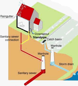
10 A pipe or conduit generally closed but not flowing full that carries sewage. Sewers are classified according to their use: o Sanitary separate sewers: carry municipal wastewater and any subsurface water (infiltration) and surface water (inflow) that enter the sewer o Storm Sewers: carry storm water o Combined sewers: carry municipal wastewater and storm water Inflow Water enters sewers from the surface during rainfall events through roof and basements drains and perforated manholes. Wastewater Sewer System 10

11 11
12 12
13 Head loss due to Friction: Head loss as a result of friction (hf) can be computed using the Hazen Williams Equation: Q 0.278Cd S Metric Units H f = KQ 1.85 Where 10.7L K 1.85 C d 4.87 Q = flow through the pipe (m 3 /s) L = pipe length (m) D = pipe diameter (m) C = Hazen-Williams coefficient = roughness coefficient Graphical solution of the Hazen-Williams equation for C = 100 can be made by the use of a nomograph. S c = S 100 (100/C) 1.85 d c = d 100 (100/C) 0.38 Q c = Q 100 (C/100) Where S = slope of the energy gradient line (E.G.L) = h f /L Example Determine the head loss in a 1000 m pipeline with a diameter of 500 mm that is discharging 0.25 m3/s. Assume that C = 130. Solution Using the Hazen-Williams equation L h f KQ Q m ,87 C d Using the nomograph for C =
14 At Q = 250 L/s and d = 500 mm S 100 = h f /L = 4.6 m/1000 m S 130 = S 100 (100/C) 1.85 = (4.6/1000) (100/130) 1.85 = 2.83/1000 h f = S L = (2.83/1000) 1000 = 2.83 m Example: A cast-iron water pipe, 400 mm in diameter, carries water at a rate of cms. Determine, by means of the Hazen-Williams formula. The slope of the hydraulic gradient of this pipe and the velocity of flow. Solution 1. Graphical solution Use the nomograph, line up the known value, diameter of a nominal 400-m pipe, and Q=0.125, and find S = m/m v = 1.09 m/s Example: An asbestos cement water pipe (C=140) with a diameter of 300 mm has a slope of the hydraulic gradient of m/m. Determine, using the Hazen-Williams formula, the capacity of the pipe and the velocity of flow. Solution 1. Graphical solution Use the nomograph, diameter of a 300-mm pipe, and s=0.0025, find Q = cms and v = 0.66 m/s However, it must be remembered that the nomograph, as indicated was constructed for C=100, whereas pipe in question has a C=140. Consequently, the value of Q and v need to be corrected. 14


15 MINOR LOSSES IN PIPES Losses caused by fittings, bends, valves, etc. 15
 Sudden enlargement Energy lost is because of turbulence.")
16 Losses are proportional to velocity of flow, geometry of 2 device. V h L K 2g The value of K is typically provided for various devices. K - loss factor - has no units (dimensionless) Sudden enlargement Energy lost is because of turbulence. Amount of turbulence depends on the differences in pipe diameters 2 V 1 h L K 2g The values of K have been experimentally determined and provided in Figures and Tables 16

17 Exit Loss Case of where pipe enters a tank a very large enlargement. The tank water is assumed to be stationery, that is, the velocity is zero. Therefore all kinetic energy in pipe is dissipated 2 V 1 h L 1.0 2g Gradual Enlargement If the enlargement is gradual (as opposed to our previous case) the energy losses are less. 17


18 The loss again depends on the ratio of the pipe diameters and the angle of enlargement. 2 V 1 h L K 2g Sudden Contraction Decrease in pipe diameter Note that the loss is related to the velocity in the second (smaller) pipe! 18

19 The loss is associated with the contraction of flow and turbulence 2 V 2 h L K 2g The section at which the flow is the narrowest Vena Contracta At vena contracta, the velocity is maximum. Energy losses for sudden contraction are less than those for sudden enlargement 19

20 Entrance Losses 20
Introduction Water supply components Preliminary studies for water supply projects:
 Introduction Water Supply, sewerage and sanitation are not only the basic necessities of life, they are also crucial for achieving the goal of Health for All. Increased sanitation coverage is directly
WASTEWATER & STORM WATER COLLECTION AND REMOVAL
 CVE 471 WATER RESOURCES ENGINEERING WASTEWATER & STORM WATER COLLECTION AND REMOVAL Assist. Prof. Dr. Bertuğ Akıntuğ Civil Engineering Program Middle East Technical University Northern Cyprus Campus CVE
Sanitary Sewer Design. Sanitary Sewers, Page 1
 Sanitary Sewer Design Sanitary Sewers, Page 1 Sanitary Sewers, Page 2 Sanitary Sewer Design sanitary sewers collect and transport domestic and industrial wastes via gravity flow the ultimate destination
CE 370. Wastewater Characteristics. Quantity. The design of a wastewater treatment plant requires knowledge of: Quantity or flowrate of wastewater.
 CE 370 Wastewater Characteristics Quantity 1 Introduction The design of a wastewater treatment plant requires knowledge of: Quantity or flowrate of wastewater. Required to determine the size of the various
Learning objectives. Upon successful completion of this lecture, the participants will be able to:
 Solomon Seyoum Learning objectives Upon successful completion of this lecture, the participants will be able to: Describe and perform the required step for designing sewer system networks Outline Design
DESIGN OF SEWER SYSTEMS
 Wastewater Engineering (MSc program) DESIGN OF SEWER SYSTEMS Prepared by Dr.Khaled Zaher Assistant Professor, Public Works Engineering Department, Faculty of Engineering, Cairo University 1. Sewer Materials
Type of Area Density (persons/ha) Large lots 5-7 Small lots, single family 75 Small lots, two family 125 Multistory apartments min.
 Large lots 5-7 Small lots, single family 75 Small lots, two family 125 Multistory apartments min.") Design of Sanitary Sewer System Key components Service connections, Manholes and pump stations Design Flows 1. Infiltration and interflow (71 to 14 m 3 /d/km). Flow from the service connections Type of
Design of Sanitary Sewer System Key components Service connections, Manholes and pump stations Design Flows 1. Infiltration and interflow (71 to 14 m 3 /d/km). Flow from the service connections Type of
Sewer system- Design Criteria
 The Islamic University of Gaza Faculty of Engineering Civil Engineering Department Sanitary Engineering (ECIV 4325) Instructor: Dr. Abdelmajid Nassar Lect. 05-07 Sewer system- Design Criteria according
The Islamic University of Gaza- Civil Engineering Department Sanitary Engineering- ECIV 4325 L5. Storm water Management
 The Islamic University of Gaza- Civil Engineering Department Sanitary Engineering- ECIV 4325 L5. Storm water Management Husam Al-Najar Storm water management : Collection System Design principles The Objectives
Basics of Wastewater Collection System
 Basics of Wastewater Collection System PDH: 3.0 Hours 1 OUTLINE Introduction Definition of Terms Types of Collections Systems Types of Sewers Shapes of Sewers Collection System Appurtenances Basic Considerations
Environmental Engineering-I
 Environmental Engineering-I Prof. Dr. Muhammad Zulfiqar Ali Khan Engr. Muhammad Aboubakar Farooq Water Distribution Systems & Analysis 1 Water Distribution Systems & Analysis References Water Supply &
WATER SUPPLY ENGINEERING
 1 WATER SUPPLY ENGINEERING (RESERVOIRS AND DISTRIBUTION SYSTEM) Compiled and Prepared By: Abhash Acharya Central Campus, Pulchowk 2 7.1 Systems of Supply: 7.1.1 Continuous System: The system of supply
SEWAGE TREATMENT AND DISPOSAL
 SEWAGE TREATMENT AND DISPOSAL QUANTITY OF SANITARY SEWAGE AND STORM WATER Zerihun Alemayehu Unpolluted cooling water Intercept or sewer Sources of Sewage Residential and commercial sewage Industrial wastewater
Module 7: Hydraulic Design of Sewers and Storm Water Drains. Lecture 7: Hydraulic Design of Sewers and Storm Water Drains
 Module 7: Hydraulic Design of Sewers and Storm Water Drains Lecture 7: Hydraulic Design of Sewers and Storm Water Drains 7.0 HYDRAULIC DESIGN OF SEWERS AND STORM WATER DRAINS 7.1 General Consideration
L3. Design Criteria of wastewater collection system
 The Islamic University of Gaza- Civil Engineering Department SanitaryEngineering- ECIV 4325 L3. Design Criteria of wastewater collection system Based on Dr. Fahid Rabah lecture notes Design of W.W. Collection
Facilities Development Manual
 State of Wisconsin Department of Transportation Facilities Development Manual ORIGINATOR Director, Bureau of Highway Development PROCEDURE 13-25-35 CHAPTER 13 Drainage SECTION 25 Storm Sewer Design SUBJECT
Wastewater Collection System
 WASTEWATER COLLECTION SYSTEM CE 370 1 Wastewater Collection System The function of the collection system is to collect the wastewater from residential, commercial, and industrial areas within the service
Environmental Engineering-I
 Environmental Engineering-I Prof. Dr. Muhammad Zulfiqar Ali Khan Engr. Muhammad Aboubakar Farooq Department of Civil Engineering The University of Lahore 1 Future Water Requirements Depend upon: 1. Selection
PRELIMINARY MUNICIPAL SERVICING REPORT NORTHWOODS SUBDIVISION. Prepared for: North Grassie Properties Inc.
 PRELIMINARY MUNICIPAL SERVICING REPORT SUBDIVISION Prepared for: North Grassie Properties Inc. Prepared by: Stantec Consulting Ltd. 905 Waverley St. Winnipeg, MB R3T 5P4 July 2012 File: 116808030 SUBDIVISION
UNIVERSITY OF BOLTON SCHOOL OF ENGINEERING. MSc CIVIL ENGINEERING SEMESTER TWO EXAMINATION 2017/2018 URBAN DRAINAGE SYSTEMS MODULE NO: BLT4022
 [ESS29] UNIVERSITY OF BOLTON SCHOOL OF ENGINEERING MSc CIVIL ENGINEERING SEMESTER TWO EXAMINATION 2017/2018 URBAN DRAINAGE SYSTEMS MODULE NO: BLT4022 Date: Monday 21 st May 2018 Time: 10:00 13:00 INSTRUCTIONS
Module 7: Hydraulic Design of Sewers and Storm Water Drains. Lecture 7 : Hydraulic Design of Sewers and Storm Water Drains
 1 P age Module 7: Hydraulic Design of Sewers and Storm Water Drains Lecture 7 : Hydraulic Design of Sewers and Storm Water Drains 2 P age 7.1 General Consideration Generally, sewers are laid at steeper
Pumps and Pumping Stations
 Pumps and Pumping Stations Pumps add energy to fluids and therefore are accounted for in the energy equation Energy required by the pump depends on: Discharge rate Resistance to flow (head that the pump
WASHOE COUNTY COMMUNITY SERVICES DEPARTMENT GRAVITY SEWER COLLECTION DESIGN STANDARDS
 GRAVITY SEWER COLLECTION DESIGN This section of the manual contains the Washoe County Community Services Department (CSD) standards for: INDEX Designing Gravity Sewer Collection Facilities ( Sewer Design
WASHOE COUNTY DEPARTMENT OF WATER RESOURCES GRAVITY SEWER COLLECTION DESIGN STANDARDS
 GRAVITY SEWER COLLECTION DESIGN This section of the manual contains the Washoe County Department of Water Resource s (DWR) standards for: Designing Gravity Sewer Collection Facilities ( Sewer Design Standards
Design of Sewerage System for Jaffarpur area in Southwest New Delhi
 International Journal of Civil Engineering Research. ISSN 2278-3652 Volume 5, Number 1 (2014), pp. 29-34 Research India Publications http://www.ripublication.com/ijcer.htm Design of Sewerage System for
SMART-DEPUR fognature smart per l ottimizzazione dei sistemi di drenaggio e depurazione dei reflui urbani
 Livorno, 28 giugno 2018 SMART-DEPUR fognature smart per l ottimizzazione dei sistemi di drenaggio e depurazione dei reflui urbani Renato Iannelli Università di Pisa DESTEC (Dipartimento di Ingegneria dell
APPENDIX G HYDRAULIC GRADE LINE
 Storm Drainage 13-G-1 APPENDIX G HYDRAULIC GRADE LINE 1.0 Introduction The hydraulic grade line is used to aid the designer in determining the acceptability of a proposed or evaluation of an existing storm
St. Boniface Industrial Park Phase 2 Municipal Servicing Report
 St. Boniface Industrial Park Phase 2 Municipal Servicing Report Prepared for: City of Winnipeg Prepared by: Stantec Consulting Ltd. File: 116809351 November 5, 2015 ST. BONIFACE INDUSTRIAL PARK PHASE 2
Sag Pipe (depressed sewers, or Inverted siphons) Dr. Sataa A. Al-Bayati(10-11)
 Dr. Sataa A. Al-Bayati(10-11)") بسم هللا الرحمن الرحيم Sag Pipe (depressed sewers, or Inverted siphons) Dr. Sataa A. Al-Bayati(10-11) A sewer that drops below the hydraulic gradient to pass under an obstruction, such as a railroad cut,
بسم هللا الرحمن الرحيم Sag Pipe (depressed sewers, or Inverted siphons) Dr. Sataa A. Al-Bayati(10-11) A sewer that drops below the hydraulic gradient to pass under an obstruction, such as a railroad cut,
Course: Wastewater Management
 Course: Wastewater Management Prof. M. M. Ghangrekar Questions 1 1. Describe advantages and disadvantages offered by the water carriage system. 2. What are the possible adverse effects when untreated or
Quantity of sewage. Dry weather flow: Domestic and industrial wastewater (Base flow) including inflow, infiltration and exfiltration
 including inflow, infiltration and exfiltration") Quantity of sewage Quantity of sewage depends on Dry weather flow and storm water Dry weather flow: Domestic and industrial wastewater (Base flow) including inflow, infiltration and exfiltration Infiltration
Quantity of sewage Quantity of sewage depends on Dry weather flow and storm water Dry weather flow: Domestic and industrial wastewater (Base flow) including inflow, infiltration and exfiltration Infiltration
SSC-JE STUDY MATERIAL ENVIRONMENTAL ENGINEERING [PA ENVIRONMENTAL ENGINEERINGG PART-A
 ART-A] Page 1 of 124 SSC-JE STAFF SELECTION COMMISSION CIVIL ENGINEERINGG STUDY MATERIAL ENVIRONMENTAL ENGINEERINGG PART-A C O N T E N T ART-A] Page 2 of 124 1. WATER DEMAND 3-22 2. SOURCES OF WATER. 23-42
Rainfall Event of September 29, Public Works & Environmental Services
 Rainfall Event of September 29, 2016 Rainfall Recorded on Revland Street Rain Gauge 220 mm of rain in 24 hours between 6:00 pm September 28 th and 6:00 am September 29 th 195 mm of rain in 12 hours between
COMPUTER APPLICATIONS HYDRAULIC ENGINEERING
 - 7535 COMPUTER APPLICATIONS IN HYDRAULIC ENGINEERING Connecting Theory to Practice Fifth Edition HAESTAD PRESS Table of Contents Revision History Foreword CHAPTER 1 BASIC HYDRAULIC PRINCIPLES 1 1.1 General
Storm Sewers, Page 2
 Storm Sewers storm sewer systems are dendritic systems used to collect and direct stormwater runoff storm sewer systems are integral components of any urban infrastructure curbs, gutters and storm inlets
Level 6 Graduate Diploma in Engineering Hydraulics and hydrology
 910-103 Level 6 Graduate Diploma in Engineering Hydraulics and hydrology Sample Paper You should have the following for this examination one answer book ordinary graph paper pen, pencil, ruler Work sheet
Storm Sewer Design - Introduction
 Class 4 [1] Storm Sewer Design - Introduction As urban drainage can not be expected to accommodate all rainfall events, the first step in the design procedure is to select an appropriate design storm.
Session 2 Pump Selection. Mark Markham, P.E. Gresham, Smith and Partners September 14, 2017
 Session 2 Pump Selection Mark Markham, P.E. Gresham, Smith and Partners September 14, 2017 Quick Refresh System Curves graphically show the relationship between flow rates and associated total dynamic
Effluent Conveyance. Paul Trotta, P.E., Ph.D. Justin Ramsey, P.E. Chad Cooper
 Effluent Conveyance Paul Trotta, P.E., Ph.D. Justin Ramsey, P.E. Chad Cooper University Curriculum Development for Decentralized Wastewater Management 1 NDWRCDP Disclaimer This work was supported by the
About Me. Overview. Seattle Regional Water System. Seattle Regional Water System. Water System Analysis and Design at Seattle Public Utilities
 About Me Water System Analysis and Design at Seattle Public Utilities Jon C. Ford, P.E. CEE 481 October 1, 8 Senior Civil Engineer, Seattle Public Utilities BSCE, Seattle University MSCE, University of
CIE4491 Lecture. Quantifying stormwater flow Rational method
 CIE4491 Lecture. Quantifying stormwater flow Rational method 27-5-2014 Marie-claire ten Veldhuis, Watermanagement Department Delft University of Technology Challenge the future Robust method stationary
D. B. G R A Y E N G I N E E R I N G I N C.
 SERVICING BRIEF 406-408 Bank Street Ottawa, Ontario Report No. 10015-SB December 13, 2011 D. B. G R A Y E N G I N E E R I N G I N C. Stormwater Management - Grading & Drainage - Storm & Sanitary Sewers
Chapter 1 Introduction
 Engineering Hydrology Chapter 1 Introduction 2016-2017 Hydrologic Cycle Hydrologic Cycle Processes Processes Precipitation Atmospheric water Evaporation Infiltration Surface Runoff Land Surface Soil water
CHAPTER 4 SYSTEM DESIGN CRITERIA
 INTRODUCTION CHAPTER 4 SYSTEM DESIGN CRITERIA Adequate design of the District s wastewater conveyance facilities requires the determination of the quantity of wastewater from contributing sources. The
SAWEA Workshop 2010 Innovative Water and Wastewater Networks Presented by Greg Welch, AECOM
 SAWEA Workshop 2010 Innovative Water and Wastewater Networks Presented by Greg Welch, AECOM Basic Hydraulic Principles Open channel flow Closed conduit / pressurized flow systems Orifices, weirs and flumes
Site Servicing & Stormwater Management Report for Site Plan Control Application. Proposed New Multi-Unit Development 284 Presland Road Ottawa, Ontario
 Site Servicing & Stormwater Management Report for Site Plan Control Application Proposed New Multi-Unit Development 284 Presland Road Ottawa, Ontario Prepared for: Martin Clement Attention: Mr. Martin
UBC Technical Guidelines Section Edition Sanitary Sewerage Utilities Page 1 of 6
 Page 1 of 6 1.0 GENERAL 1.1 Related UBC Guidelines.1 338201s CCTV Pipeline Inspection (see http://energy.ubc.ca/communityservices/contractors-developers/).2 330130.41s Cleaning of Sewers (link as above)
SAMPLE STUDY MATERIAL. GATE, IES & PSUs Civil Engineering
 SAMPLE STUDY MATERIAL Postal Correspondence Course GATE, IES & PSUs Civil Engineering Environmental Engineering-A Water Supply C O N T E N T 1. WATER DEMAND 3-11 2. SOURCES OF WATER. 12-27 3. CONDUITS
Wastewater Flow Monitoring Services
 Wastewater Flow Monitoring Services For San Gabriel, CA July 13, 2015 through July 21, 2015 Revised October 9, 2015 Leaders in Sewer Flow Monitoring Services 601 N. Parkcenter Dr., Suite 209 Santa Ana,
2. DEFINITIONS. American Association of State Highway and Transportation Officials.
 2. DEFINITIONS 2.010 Definitions [See Amendment 2] In addition to words and terms that may be defined elsewhere in this manual, the following words and terms shall have the meanings defined below: AASHTO:
CHAPTER 4 DESIGN CRITERIA
 CHAPTER 4 DESIGN CRITERIA 4.1 INTRODUCTION This chapter summarizes the basic design criteria necessary to develop options and sizing estimates for the components of centralized wastewater collection systems.
SCHAEFFERS FUNCTIONAL SERVICING REPORT PROPOSED RESIDENTIAL DEVELOPMENT LAKESHORE ROAD WEST TOWN OF OAKVILLE
 FUNCTIONAL SERVICING REPORT PROPOSED RESIDENTIAL DEVELOPMENT 346 362 LAKESHORE ROAD WEST TOWN OF OAKVILLE PROJECT 2016-4442 JULY 2017 REVISED: APRIL 2017 C O N S U L T I N G E N G I N E E R S 64 Jardin
UNIVERSITY OF BOLTON WESTERN INTERNATIONAL COLLEGE FZE BENG (HONS) CIVIL ENGINEERING SEMESTER ONE EXAMINATION 2015/2016
 CIVIL ENGINEERING SEMESTER ONE EXAMINATION 2015/2016") OCD63 UNIVERSITY OF BOLTON WESTERN INTERNATIONAL COLLEGE FZE BENG (HONS) CIVIL ENGINEERING SEMESTER ONE EXAMINATION 015/016 WATER ENGINEERING AND THE ENVIRONMENT MODULE NO: CIE601 Date: 15 January 016
OCD63 UNIVERSITY OF BOLTON WESTERN INTERNATIONAL COLLEGE FZE BENG (HONS) CIVIL ENGINEERING SEMESTER ONE EXAMINATION 015/016 WATER ENGINEERING AND THE ENVIRONMENT MODULE NO: CIE601 Date: 15 January 016
Modelling and Analysis of EES Systems Using SWMM
 Planning and Design of a Right-of-Way LID (Etobicoke Exfiltration System) July 24 th 2015 Toronto, Ontario, Canada ling and Analysis of EES Systems Using SWMM Darko Joksimovic Department of Civil Engineering,
Irrigation Rehabilitation Program Design and Construction Standards
 Irrigation Rehabilitation Program Design and Construction Standards Prepared by the IRP Standards Review Committee For Alberta Agriculture and Rural Development, Irrigation Secretariat April 26, 2010 Adopted
ENGINEERING REPORT WATER SUPPLY
 PROPOSED RESIDENTIAL DEVELOPMENT, CORAL SPRINGS TRELAWNY FCS #: 1124/76/C ENGINEERING REPORT WATER SUPPLY PREPARED FOR Gore Developments Limited 2c Braemar Ave, Kingston 10 FEBRUARY 2012 1 TABLE OF CONTENTS
ENGINEERING REVIEW CHECKLIST City of Mount Clemens
 (To be completed by the Developer s & Submitted with ing Plans) DATE: PROJECT NAME: Site Plan Approved: Date DESIGN ENGINEERING COMPANY: ing Company Contact Information: Name: Phone: Email: Owner Contact
New Retirement Home 6758 & 6766 Rocque Street Orleans, Ontario
 New Retirement Home 6758 & 6766 Rocque Street Orleans, Ontario Site Servicing and Stormwater Management Report By Mohamad Salame, P.Eng. Kamco Technique Ltee. 60 Grand Avenue North Cambridge, Ontario N1S
Estimation of Parameters and Flow Characteristics for the Design of Sanitary Sewers in Malaysia
 Estimation of Parameters and Flow Characteristics for the Design of Sanitary Sewers in Malaysia KAMRAN ANSARI*, ZAHEER AHMED ALMANI*, AND NAEEM AZIZ MEMON* RECEIVED ON 25.02.2012 ACCEPTED ON 18.09.2012
Julia Bahen, Urban Strategies Inc.
 THE MUNICIPAL INFRASTRUCTURE GROUP LTD. 8800 Dufferin Street, Suite 200 Vaughan, Ontario L4K 0C5 T 905.738.5700 F 905.738.0065 www.tmig.ca TECHNICAL MEMORANDUM DATE June 13, 2017 TO CC SUBJECT FROM PROJECT
Lynn Township Sewer Authority. Corrective Action Plan. March 2007
 Lynn Township Sewer Authority Corrective Action Plan March 2007 4130.00 Prepared By: ARRO Consulting, Inc. 400 Washington Street, Suite 602 Reading, Pennsylvania 19610 610 374 5285 Corrective Action Plan
Introduction to Storm Sewer Design
 A SunCam online continuing education course Introduction to Storm Sewer Design by David F. Carter Introduction Storm sewer systems are vital in collection and conveyance of stormwater from the upstream
City of Logan Sanitary Sewer Design Standards
 City of Logan Sanitary Sewer Design Standards 2011 http://www.loganutah.org/public_works/engineering/stdsspecsdesign.cfm Table of Contents PART 1. CITY OF LOGAN SANITARY SEWER SYSTEM DESIGN STANDARDS FOR
HY-12 User Manual. Aquaveo. Contents
 Y-12 User Manual Aquaveo Contents Overview...2 Watershed Parameters...3 Channel Parameters...3 Storm Drain Parameters...3 Design of new systems...4 Analysis of existing systems...4 Steady flow...4 ydrographic
STORMWATER MANAGEMENT REPORT. Dundas Square Gardens Inc. High Rise Residential/Commercial Development
 STORMWATER MANAGEMENT REPORT Dundas Square Gardens Inc. Revised: April 6, 2016 Revised: January 12, 2016 Revised: July 10, 2015 OUR FILE: 14-RE-352 June 16, 2014 TABLE OF CONTENTS PAGE 1.0 Scope of work
3.0 DESIGN CRITERIA FOR SANITARY SEWER FACILITIES
 3.0 DESIGN CRITERIA FOR SANITARY SEWER FACILITIES All sanitary sewers shall be designed in accordance with these Design Standards, LBWD Rules and Regulations, and to accepted engineering principles. In
PART V - STORM DRAIN DESIGN CRITERIA
 PART V - STORM DRAIN DESIGN CRITERIA A. Hydrology Studies and Hydraulic Analyses 1. Drainage area master plans and calculations are to be submitted with all subdivision improvement plans, permit improvement
PART V - STORM DRAIN DESIGN CRITERIA
 PART V - STORM DRAIN DESIGN CRITERIA A. Hydrology Studies and Hydraulic Analyses 1. Drainage area master plans and calculations are to be submitted with all subdivision improvement plans, permit improvement
Dunpar Developments Inc.
 Dunpar Developments Inc. Proposed Townhouse Development 2158, 2168, 2180 and 2192 Trafalgar Road Oakville, Ontario Functional Servicing and Stormwater Management Report (in Support of a Re-Zoning and Site
Storm Sewer Design. Bob Pitt University of Alabama and Shirley Clark Penn State Harrisburg
 Storm Sewer Design Bob Pitt University of Alabama and Shirley Clark Penn State Harrisburg Major floods are dramatic and water flow routes must be recognized when minor drainage systems fail. These types
Fluid Mechanics. The Energy Equation [7] Dr. Mohammad N. Almasri
![Fluid Mechanics. The Energy Equation [7] Dr. Mohammad N. Almasri](/thumbs/77/76088370.jpg "Fluid Mechanics. The Energy Equation [7] Dr. Mohammad N. Almasri") 1 Fluid Mechanics The Energy Equation [7] Dr. Mohammad N. Almasri http://sites.google.com/site/mohammadnablus/home 2 Introduction There are various types of devices and components that are utilized in
1 Fluid Mechanics The Energy Equation [7] Dr. Mohammad N. Almasri http://sites.google.com/site/mohammadnablus/home 2 Introduction There are various types of devices and components that are utilized in
DRAINAGE & DESIGN OF DRAINAGE SYSTEM
 Drainage on Highways DRAINAGE & DESIGN OF DRAINAGE SYSTEM P. R.D. Fernando Chartered Engineer B.Sc.(Hons), M.Eng. C.Eng., MIE(SL) Drainage Requirement of Highway Drainage System Introduction Drainage means
PART 3 - STANDARDS FOR SEWERAGE FACILITIES DESIGN OF STORM SEWERS
 PART 3 - STANDARDS FOR SEWERAGE FACILITIES 3.3 - DESIGN OF STORM SEWERS 3.301 Design of Storm Sewers A. General Information B. Investigations and Surveys C. Special Projects 3.302 Design Criteria for Storm
Module 2 : System of Sanitation. Lecture 2 : System of Sanitation
 1 P age Module 2 : System of Sanitation Lecture 2 : System of Sanitation 2 P age 2.1 BACKGROUND For safe disposal of the sewage generated from a locality efficient collection, conveyance, adequate treatment
Landfill design General principles
 Landfill design General principles Average height of a landfill should be at least 15 m Each section (cell) should accommodate waste to be landfilled during 5 years period Sections/cells should be hydraulically
D. B. G R A Y E N G I N E E R I N G I N C.
 SERVICING BRIEF 2200 Prince of Wales Drive Ottawa, Ontario Report No. 11068-SB February 3, 2012 D. B. G R A Y E N G I N E E R I N G I N C. Stormwater Management - Grading & Drainage - Storm & Sanitary
DIVISION 5 STORM DRAINAGE CRITERIA
 DIVISION 5 STORM DRAINAGE CRITERIA Section 5.01 GENERAL The following storm drainage design criteria shall apply to all storm drainage designs in the City. Additional design criteria are specified in the
Functional Servicing Report. Winston Park West Proposed Business Park Development Project. Infrastructure Ontario (IO) September MU1
 September MU1") Functional Servicing Report Winston Park West Proposed Business Park Development Project (IO) September 2011 14-11208-001-MU1 Winston Park West 2 TABLE OF CONTENTS Page 1.0 INTRODUCTION... 3 1.1 SITE DESCRIPTION...
Functional Servicing Report Winston Park West Proposed Business Park Development Project (IO) September 2011 14-11208-001-MU1 Winston Park West 2 TABLE OF CONTENTS Page 1.0 INTRODUCTION... 3 1.1 SITE DESCRIPTION...
City of Crosby, ND Municipal Infrastructure Needs Assessment September 2012
 City of Crosby, ND Municipal Infrastructure Needs Assessment September 2012 Project made possible by US Dept. of HUD Regional Substantiality Planning Grant and ND Energy Development Infrastructure and
CITY OF SASKATOON DESIGN AND DEVELOPMENT STANDARDS MANUAL SECTION FOUR WATER DISTRIBUTION SYSTEM
 CITY OF SASKATOON DESIGN AND DEVELOPMENT STANDARDS MANUAL SECTION FOUR WATER DISTRIBUTION SYSTEM 2018 TABLE OF CONTENTS Section Four Water Distribution System SECTION PAGE NUMBER 1. Objective...1 2. Submissions
Index. Page numbers followed by f indicate figures.
 Index Aerodynamic method, 103, 110 111 Algae, 131, 173, 175 Alternate depth, 88 Alternating block method, 132, 140 141 Attenuation, 106, 107f, 118, 120 Page numbers followed by f indicate figures. Baseflow
Detention Pond Design Considering Varying Design Storms. Receiving Water Effects of Water Pollutant Discharges
 Detention Pond Design Considering Varying Design Storms Land Development Results in Increased Peak Flow Rates and Runoff Volumes Developed area Robert Pitt Department of Civil, Construction and Environmental
ENGINEERING STANDARD FOR DRAIN AND SEWER SYSTEMS OUTSIDE BUILDINGS FIRST EDITION NOVEMBER 2013
 ENGINEERING STANDARD FOR DRAIN AND SEWER SYSTEMS OUTSIDE BUILDINGS FIRST EDITION NOVEMBER 2013 This Standard is the property of Iranian Ministry of Petroleum. All rights are reserved to the owner. Neither
CEE 371 May 14, 2009 Final Exam
 CEE 371 May 14, 2009 Final Exam Closed Book, two sheets of notes allowed Please answer questions 3, 6 and 7. In addition, answer either question 1 or 2, and answer either question 4 or 5. The total potential
HERPIC County Storm Drainage Manual
 HERPIC County Storm Drainage Manual C h r is t o p h e r B. B u r k e Research Assistant Highway Extension and Research Project for Indiana Counties Purdue University The HERPIC (Highway Extension and
EPANET. Ivan Solinas
 EPANET Ivan Solinas agronomi@gmail.com The Irrigation Questions How to irrigate How much to irrigate When to Irrigate Pressurized pipe network What is EPANET EPANET is a computer program that performs
DRAINAGE OF IRRIGATED LANDS
 CVE 471 WATER RESOURCES ENGINEERING DRAINAGE OF IRRIGATED LANDS Assist. Prof. Dr. Bertuğ Akıntuğ Civil Engineering Program Middle East Technical University Northern Cyprus Campus CVE 471 Water Resources
D. B. G R A Y E N G I N E E R I N G I N C.
 SERVICING BRIEF Mutchmor Public School Addition 185 Fifth Avenue Ottawa, Ontario Report No. 12073-SB February 15, 2013 D. B. G R A Y E N G I N E E R I N G I N C. Stormwater Management - Grading & Drainage
THE STUDY ON INTEGRATED URBAN DRAINAGE IMPROVEMENT FOR MELAKA AND SUNGAI PETANI IN MALAYSIA FINAL REPORT
 THE GOVERNMENT OF MALAYSIA PRIME MINISTER S DEPARTMENT ECONOMIC PLANNING UNIT THE STUDY ON INTEGRATED URBAN DRAINAGE IMPROVEMENT FOR MELAKA AND SUNGAI PETANI IN MALAYSIA FINAL REPORT VOL. 5: TECHNICAL
EXAMPLE SHEET FOR TOPIC 2 AUTUMN Q1. What is the significance of the Reynolds number Re for the flow of fluid in a circular pipe?
 EXMPLE SHEET FOR TOPI 2 UTUMN 2013 Q1. What is the significance of the Reynolds number Re for the flow of fluid in a circular pipe? If the friction factor for a pipe is given by λ = 64/Re for laminar flow,
PROPOSED FIVE STOREY MIXED USE BUILDING DEVELOPMENT SITE LOT 2 R PLAN M BANK STREET CITY OF OTTAWA STORM DRAINAGE REPORT
 PROPOSED FIVE STOREY MIXED USE BUILDING DEVELOPMENT SITE LOT 2 R PLAN M 2 7 BANK STREET CITY OF OTTAWA STORM DRAINAGE REPORT REPORT R 81 41 (REV. 2) MARCH 2017 T.L. MAK ENGINEERING CONSULTANTS LTD. JULY
The Uplands - Combined Sewer Separation Project Pre-Design Phase Technical Memo 1
 Prepared for the FINAL November 2015 The Uplands - Combined Sewer Separation Project Pre-Design Phase Technical Memo 1 RFP No. OBMH-02-2015 November 18, 2015 Submitted by: McElhanney Consulting Services
10 LOUISA STREET - THORNBURY
 10 LOUISA STREET - THORNBURY Town of The Blue Mountains Functional Servicing Report prepared by: C.C. Tatham & Associates Ltd. 115 Sandford Fleming Drive, Suite 200 Collingwood, ON L9Y 5A6 Tel: (705) 444-2565
SOUTHEAST TEXAS CONTINUING EDUCATION
 EXAM No. 118 FLOOD - RUNOFF ANALYSIS 1. Information gained from flood - runoff analysis includes which one: A. Stage, discharge, volume. B. Measure depth, volume. C. Velocity, depth, storm occurrence.
Infiltration and Inflow. Michael Sassaman Phone
 Infiltration and Inflow Michael Sassaman msassaman@entecheng.com Phone 610-373-3345 Inflow and Infiltration PA DEP Learning Objectives Do you have Excessive I/I? Sources of Inflow and Infiltration I/I
HSA SEWER PROJECT FAQs
 HSA SEWER PROJECT FAQs Q1: Why do some residents in the Phase II project area have only 45 days to comply with the HSA water tightness regulations? A1: Some homeowners in the Phase II project area are
Chapter 6 STEP System Force Main Velocity Evaluation
 Chapter 6 STEP System Force Main Velocity Evaluation \\7348101\TOC.doc CHAPTER 6 STEP System Force Main Velocity Evaluation 6.1 INTRODUCTION The City s existing STEP (septic tank effluent pump) pumps currently
Regional Hydraulic Model Plan
 APPENDIX 3 Regional Hydraulic Model Plan November 17, 2008 Contents Section 1 Introduction Section 2 Model Objectives and Capabilities 2.1 Model Software Capabilities... 2-1 Section 3 Model Development
Pipe & Fittings Water & Sewer. Design Guide
 Pipe & Fittings Water & Sewer Design Guide A World of Choice Saint-Gobain Pipelines is the UK s leading supplier of ductile iron pipe systems for potable water and sewerage applications. Saint-Gobain Pipelines
City of Grosse Pointe Park Sanitary Sewer System Inflow and Infiltration Investigation Smoke Testing
 City of Grosse Pointe Park Sanitary Sewer System Inflow and Infiltration Investigation Smoke Testing August 2017 Definitions Sanitary Sewer System Sanitary sewer pipes and pump stations that collect wastewater