McCarran International Airport Terminal 3
|
|
|
- Stephen Floyd
- 6 years ago
- Views:
Transcription

1 McCarran International Airport Terminal 3 The Pennsylvania State University Architectural Engineering Senior Thesis Final Report Evaluation of Underfloor Air Distribution and Displacement Ventilation Systems April 9, 2008 Prepared By: Jason A. Witterman Faculty Advisor: William Bahnfleth, Ph.D., P.E.
2
3 Table of Contents Executive Summary... 6 Architectural Background... 7 Figure 1: McCarran International Airport Site Plan... 7 Figure 2: Exterior Rendering of Terminal Mechanical Systems Background... 9 Waterside Cooling Equipment Summary... 9 Table 1: Chilled Water and Condenser Water System Control Valve Matrix Figure 3: Chilled Water Schematic Figure 4: Condenser Water Schematic Waterside Heating Equipment Summary Figure 5: Heating Hot Water Schematic Airside Equipment Summary Outline of Mechanical System Redesign Background Information Figure 6: Level 2 Key Plan Figure 7: Interior rendering of typical gate holdroom and airside concourse. (Courtesy of PGAL, LLC) Design Goals System Selection Justification for Investigation Calculation of Revised Space and System Loads Background and Explanation of Load Differences Table 2: Design Outdoor Conditions Table 3: Indoor Design Conditions Load Factors for Underfloor Air Distribution Systems Table 4: Load Factors for Underfloor Air Distribution Systems Load Factors for Displacement Ventilation Systems Table 5: Load Factors for Displacement Ventilation Systems Calculation Procedure and Summary of Resultant Loads Table 6: Comparison of Loads for Traditional and DV Systems Table 7: Comparison of Loads for Traditional and UFAD Systems Calculation and Comparison of Outdoor Air Flow Rates Background and Assumptions Calculation Procedure Evaluation of Underfloor Air Distribution and Displacement Ventilation Systems 3
4 Discussion of Results Table 8: Summary of Outdoor Air Flow Rates for Existing Systems Table 9: Summary of Outdoor Air Flow Rates for Redesigned Systems Calculation of New Supply Air Quantities and Temperatures Calculation Procedure for Underfloor Air Distribution Systems Table 10: Sample Calculation for Gate 01 Holdroom Supply Air Flow Rate and Air Temperatures Table 11: Comparison of Supply Air Quantities for Traditional and UFAD Systems Calculation Procedure for Displacement Ventilation Systems Table 12: Sample Calculation for Gate 01 Airside Concourse Supply Air Flow Rate and Air Temperatures Table 13: Comparison of Supply Air Quantities for Traditional and DV Systems Load Calculation Conclusions New System Zoning and Air Handling Units Explanation of New Zoning for Area of Redesign Zone Assignments and Location of New Air Handling Equipment Figure 8: Section Through Egress Stairs Figure 9: Location of Egress Stairs Table 14: Summary of Redesigned Air Handling Units System Components and Proposed Layout Figure 10: Plan of Rooms Included in Typical Design Area Underfloor Air Distribution Equipment Selections and Typical Layout Figure 11: Linear Floor Grille for UFAD Figure 12: RFID Round Diffuser and DB Basket Displacement Ventilation Equipment Selections and Typical Layout Figure 13: DF1 Displacement Diffuser and Duct Cover Energy Consumption and Cost Analysis Differences in Initial Equipment Costs Table 15: Cost Comparison for UFAD and Traditional Overhead Systems Table 16: Cost Comparison for DV and Traditional Overhead Systems Table 17: Cost Comparison for Existing and New Air Handling Units Energy Savings Associated with Increased Economizer Operation Table 18: Economizer Energy Savings for UFAD Systems Table 19: Economizer Energy Savings for DV Systems Comparison of Annual Energy Consumption Table 20: Utility Rates Evaluation of Underfloor Air Distribution and Displacement Ventilation Systems 4
5 Table 21: Annual Energy Consumption Comparison Table 22: Annual Operating Cost Comparison Mechanical System Redesign Conclusions Acoustical Design Breadth Background Information and Existing Conditions Analysis Performed Conclusions Figure 14: NC 33 Graph for Supply Air Fan; NC 31 Graph for Return Air Fan Table 23: Sound Attenuator Savings Access Floor Design Breadth Background Information Architectural and Structural Analysis Construction Cost and Scheduling Impacts Conclusions Final Conclusions and Recommendations References Appendix A ASHRAE Standard Calculations Appendix B Zone Assignments for Air Handling Units Appendix C Trane Acoustical Program Calculation Results Appendix D Access Floor Cost and Scheduling Estimates Acknowledgments I d like to thank the following individuals and organizations for their assistance: Thesis Advisor Dr. William Bahnfleth, P.E. Other AE Faculty Dr. Jim Freihaut Professor Moses Ling, P.E., R.A. Building Owner for Permission to Study Terminal 3 Clark Country Department of Aviation Mechanical Design Engineer for Terminal 3 Roger L. Arnold, Jr, P.E., LEED AP Architect for Terminal 3 PGAL, LLC Evaluation of Underfloor Air Distribution and Displacement Ventilation Systems 5
6 Executive Summary This report is an evaluation of Underfloor Air Distribution (UFAD) and Displacement Ventilation (DV) systems compared to traditional overhead mixing HVAC systems. The areas of application for these systems are the gate holdrooms and airside concourse of Terminal 3 at McCarran International Airport in. The design process is discussed throughout the report and includes load calculations, ventilation requirements, equipment selections, cost comparisons, and other considerations. Load calculations for Terminal 3 are performed using Trane TRACE software. This software is used to model the spaces of interest based on the existing mechanical system configuration. From here, various load factors are applied to the spaces to determine the load present in the occupied zones. These occupied zone loads are then used to determine the necessary capacity of the redesigned airside systems. An additional 92,532 CFM is required in the spaces served by the UFAD systems; and an additional 36,162 CFM is required in those spaces served by the DV systems. Outdoor air ventilation rates are calculated in accordance with ASHRAE Standard Based on the work performed with regards to this standard, the ventilation effectiveness of both UFAD and DV systems is higher than it is for the existing overhead mixing system. As such, supply outdoor air flow rates required at the outdoor air louvers can be reduced by 52,677 CFM. Unfortunately, the redesigned system has an associated increase in first cost. This is partly due to the requirement of nine additional air handlers, and partly due to the need for additional terminal units and diffusers within the various spaces. The total increase in first cost is approximately $1,051,280. Potential changes in annual operating costs are also analyzed based on simulations performed in TRACE. Even with reduced outdoor air flow rates and increased economizer operation, annual operating costs still increase due to the larger amount of supply air required. This increase in operating cost is approximated as $158,650 per year. Given the large size of Terminal 3, these costs are relatively minimal compared to the total building costs. Regardless, these increases are not ideal and detract from the potential benefits of the system. Since the UFAD system will require an underfloor air plenum, an access floor will be installed in the gate holdroom areas. This will require some structural modifications to ensure that a smooth transition can be made from the raised floor to the adjacent existing floor. While the structural impacts of the raised floor are within reason, there are some architectural impacts that are not ideal. Furthermore, the raised floor has a substantial cost of about $985,000 associated with it. An acoustical analysis is also performed with regards to noise from mechanical system fans. This analysis indicates that the redesigned system will allow for the removal of existing sound attenuators and duct lagging in the area of redesign. The removal of this equipment results in an estimated savings of $45,000 in initial costs. In general, the replacement of the existing overhead distribution system is not recommended. While there are potential benefits to UFAD and DV systems, they are not appropriate for a facility of this nature. They may, however, be appropriate for other building types. Evaluation of Underfloor Air Distribution and Displacement Ventilation Systems 6


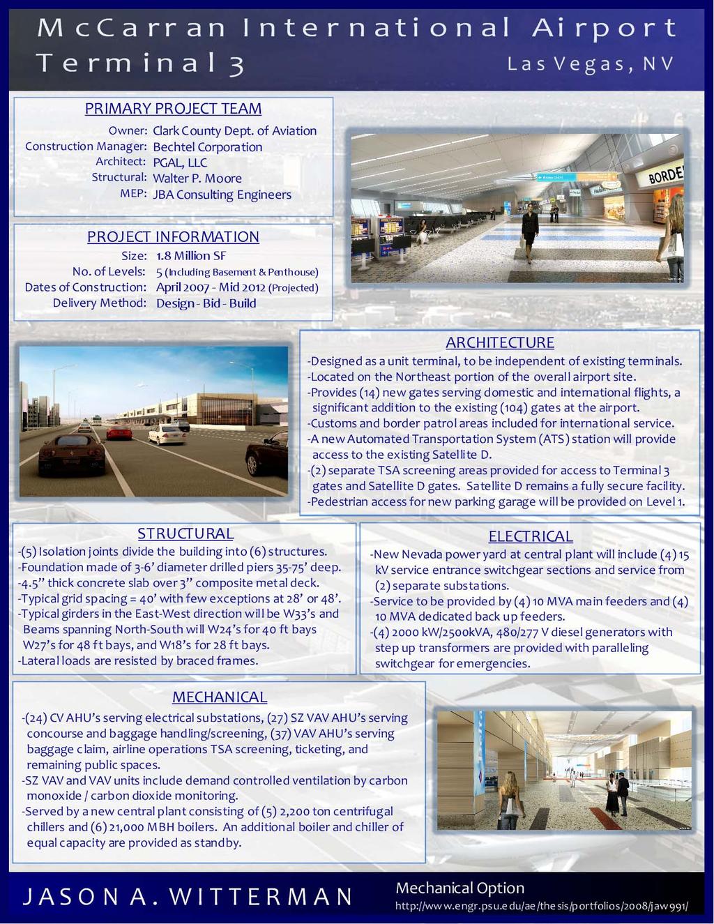
7 Architectural Background Terminal 3 is a 1.8 million SF facility being developed on the northeast portion of the airport site. It will be a unit terminal at McCarran International Airport, as it will not be dependent on the existing terminals. The new terminal will provide 14 new gates serving both domestic and international flights. As a result, Terminal 3 will also include customs and border patrol services. Figure 1 shows the location of Terminal 3 relative to the remainder of McCarran International Airport, while Figure 2 shows an exterior rendering of the terminal. Terminal 3 is pictured to the lower right of this rendering, with Satellite D appearing to the left. In the distance, one can see the Las Vegas Strip. Figure 1: McCarran International Airport Site Plan Figure 2: Exterior Rendering of Terminal 3 (Courtesy of PGAL, LLC) Evaluation of Underfloor Air Distribution and Displacement Ventilation Systems 7
8 Terminal 3 consists of five levels. The below grade basement level includes mechanical and electrical rooms, storage, and Automated Transportation System (ATS) maintenance areas. Level 0 is below grade on the airside of the terminal, and at grade on the landside. It includes baggage claim, customs, an ATS station serving Satellite D, and back of house support facilities. This level also contains TSA passenger screening as Satellite D is a fully secure building. Level 1 is at grade on the airside of the terminal and above grade on the landside. It houses the baggage screening systems, airline support area, and other back of house facilities. This level is fully secure with the exception of a landing connecting Level 0 and Level 2. This landing will provide access from a new parking garage to be built with Terminal 3. Level 2 contains the new gates, concessions, gaming areas, concourses, ticketing counters, offices, and additional back of house facilities. Level 3 of the terminal consists only of mechanical penthouse spaces. Special attention is drawn to the requirement for full separation of secure and non secure areas of the new terminal. The following terms are used throughout this report, and are defined here for clarification. The landside portion of the terminal refers to the unsecure portions of the terminal that do not require one to first pass through Transportation Security Administration (TSA) screening areas. The airside portion of the terminal refers to those areas that can only be accessed after having passed through TSA screening lanes. A new central plant is being constructed to serve Terminal 3. This central plant will be located to the east of the terminal. As stated before, Terminal 3 also includes an ATS station with a tunnel connecting the terminal to the existing Satellite D facility. Evaluation of Underfloor Air Distribution and Displacement Ventilation Systems 8
9 Mechanical Systems Background Waterside Cooling Equipment Summary A peak cooling capacity of 11,000 tons is provided by a variable primary flow chilled water system. This peak capacity is supplied by five 2,200 ton centrifugal chillers. An additional 2,200 ton centrifugal chiller will be provided as standby for a total of six chillers. Three variable flow chilled water pumps are provided to serve the cooling load, with an additional chilled water pump provided as standby. This results in a total of four chilled water pumps. These pumps are horizontal split case to maintain consistency with the existing central plant. The pumping arrangement is such that the chilled water pumps are decoupled from the chillers. Therefore, any chilled water pump or group of chilled water pumps can operate with any chiller or group of chillers. The condensing water system for the central plant consists of field erected concrete cooling towers. There are a total of six cells corresponding to the six chillers. Again, five of the cooling towers are provided to serve the cooling load, and one additional cell is provided as standby. The condenser water system is a constant flow system, with five condenser water pumps serving the condenser water load. An additional condenser water pump is provided as standby for a total of six condenser water pumps. Similar to the chilled water pumps and chillers, the condenser water pumps are decoupled from the cooling towers. This allows for any one condenser water pump or group of condenser water pumps to operate with any one cooling tower or collection of cooling towers. Variable Frequency Drives (VFD s) will be included on the cooling tower fan motors to maintain appropriate condenser water temperatures. All chillers, cooling towers, and heat exchangers have associated isolation valves. When a given chiller or cooling tower is energized, the respective isolation valve shall be open. In contrast, when a given chiller or cooling tower is de energized, the respective isolation valve shall be closed. Similarly, when a heat exchanger is to be in operation, the associated isolation valve shall open. When a heat exchanger is no longer in operation, the isolation valve shall be closed. The plant itself is also provided with valves to isolate it from the remainder of the system. These valves are pneumatic, and controlled locally within the plant. The Building Management System (BMS) is alarmed in the event the plant isolation valves are closed. The chilled water system is designed with three potential operating modes. These include mechanical refrigeration, chilled water return pre cooling, and waterside free cooling. These operating modes are controlled by several operating mode system valves as shown in Figure 3: Chilled Water Schematic, and Figure 4: Condenser Water Schematic. Table 1 indicates the position of these system valves for the various operating modes. A total of two plate and frame heat exchangers are provided for chilled water return pre cooling and waterside free cooling. Since the chilled water return pre cooling mode will require the use of condenser water at two separate temperatures, the basin is divided by two sluice gates. When closed, these gates create two separate water basins served by different cooling towers. Evaluation of Underfloor Air Distribution and Displacement Ventilation Systems 9
10 Operation Mode Chilled Water Valves Condenser Water Valves V 1 V 2 V 3 V 4 V 5 V 6 Mechanical Refrigeration Open Closed Closed Closed Open Open Chilled Water Return Pre Cooling Closed Open Closed Closed Closed Closed Waterside Free Cooling Closed Closed Open Closed Open Open Table 1: Chilled Water and Condenser Water System Control Valve Matrix Figure 3: Chilled Water Schematic Figure 4: Condenser Water Schematic Evaluation of Underfloor Air Distribution and Displacement Ventilation Systems 10
11 Mechanical Refrigeration In this mode, the chillers are operated as required to maintain the plant leaving water temperature setpoint of 42 F. Chilled water pumps are also operated as required to satisfy the chilled water demand. In addition, the cooling towers are staged as required to satisfy the condenser water demand of the chillers. The condenser water supply setpoint is set to 85 F. Chilled Water Return Pre Cooling In this operating mode, chilled water return water (CHR) passes through one or both of the heat exchangers (HX 1, HX 2) prior to entering the chillers. Operation in this mode requires that the sluice gates (SG 1, SG 2) be closed to separate the cooling tower basin into two basins. One portion of the basin makes condenser water for the chillers at a condenser water supply temperature of 52 F, while the other portion makes water as cold as ambient conditions will allow for use in the heat exchangers. The desired condenser water supply temperature for use in the heat exchangers is 38 F. The chillers are utilized in this mode to provide the remaining cooling required that is not performed in the heat exchangers. The portion of the system making condenser water for the chillers includes cooling towers CT 3, CT 4, CT 5, and CT 6; as well as condenser water pumps P 7, P 8, P 9, and P 10. No chillers are utilized by this side of the system. Any chiller and any chilled water pump are permitted to operate in this mode. The portion of the system providing colder condenser water for the heat exchangers is served by cooling towers CT 1, and CT 2; as well as condenser water pumps P 5, and P 6. When seasonal weather permits this mode of operation to be successful, the sluice gates will be manually closed. The condenser water pump headers are also separated, but through automatic control. The condenser water system is now divided into a hot system for use by the chillers, and a cold system for use by the heat exchangers. When the outside air wet bulb temperature falls to 10 F below the chilled water return temperature, the BMS shall index the system to operate in the chilled water return pre cooling mode. At this time, the isolation valves on both the chilled water and condenser water sides of the heat exchangers are opened. The BMS shall then position system valves as indicated in Table 1. When the cold system condenser water temperature is 2 F less than the chilled water return temperature for duration of five continuous minutes, the BMS places the chilled water system into mechanical refrigeration mode. Once the system valves are positioned to allow for full chilled water return flow to the chillers, the BMS closes all isolation valves on the heat exchanger. Waterside Free Cooling In this mode, all chillers are de energized. The cooling towers operate in sequence to make water for the heat exchangers that will maintain the plant leaving water temperature setpoint. The condenser water supply setpoint is set to 38 F. Chilled water pumps are again staged as necessary to satisfy the chilled water demand of the system. Operation in this mode is set when the outside air wet bulb temperature falls to 38 F. At this time, the BMS shall stage off any chillers that are in operation and open the isolation valves on both the chilled water and condenser water sides of the heat exchanger. The BMS shall then position system valves as indicated in Table 1. If the chilled water supply temperature rises to 49 F for five minutes, the BMS shall place the chilled water system into the chilled water pre cooling mode. Evaluation of Underfloor Air Distribution and Displacement Ventilation Systems 11
12 Waterside Heating Equipment Summary A peak heating capacity of 105,840,000 Btu/h is provided by a primary / secondary heating hot water system. This peak capacity is supplied by six 21,000 MBH flexible water tube boilers. The total input capacity of these boilers is 126,000 MBH, and the boilers have an efficiency rating of 84%. The resulting output capacity is therefore 105,840,000 Btu/h. An additional 21,000 MBH input boiler is provided as standby for a total of seven boilers. The primary heating hot water loop includes six constant flow hot water primary pumps to serve the heating load. An additional hot water primary pump is provided as standby. The secondary heating hot water loop includes three variable flow hot water secondary pumps to serve the heating load. Again, an additional hot water secondary pump is provided as standby. Both primary and secondary hot water pumps will be horizontal split case piped with common headers to allow the operation of any pump with any boiler. Figure 5 shows the schematic for the heating hot water system. Similar to the chilled water system, the equipment on the heating hot water system also has associated isolation valves. When a boiler is energized, the associated isolation valve shall be open. When a boiler is de energized, the respective isolation valve shall then be closed. The heating hot water system also has plant isolation valves that allow the plant to be isolated from the remainder of the system. These valves are pneumatic, and controlled locally within the plant. A closed plant isolation valve is set to alarm the BMS. Figure 5: Heating Hot Water Schematic The heating hot water supply temperature setpoint is 200 F. The building heating load demand is determined through the measurement of heating hot water flow rate, as well as supply and return temperatures of the heating hot water. These flow meters are identified on the heating hot water system schematic. Direct / indirect evaporative coolers are provided at the central plant to provide conditioned and filtered make up air to the boiler room. The VFD s on these evaporative coolers will be controlled by the BMS to provide the required quantity of combustion air based on the number of boilers to be operating. Once Evaluation of Underfloor Air Distribution and Displacement Ventilation Systems 12
13 this is achieved, the BMS opens the lead boilers heating hot water isolation valve and the lead heating hot water primary pump. Next, the lead heating hot water secondary pump is energized. If the boilers in operation have been on for 20 minutes and the heating hot water supply temperature is 5 F or less below the setpoint for five continuous minutes, then additional boilers shall be staged on. In contrast, if the system heating load decreases below the capacity of an online boiler for five continuous minutes, then the boiler with the highest total accumulated run time is disabled. Airside Equipment Summary Terminal 3 is served by 88 air handling units, with an additional three units serving the central plant. With the exception of those units serving the baggage handling areas, electrical substations, and chiller rooms; all of these air handling units have a carbon dioxide monitoring system. Similarly, the air handling units serving the baggage handling areas include a carbon monoxide monitoring system due to the operation of combustion engine driven baggage tugs. Each of these sensors allows for demand controlled ventilation in accordance with ASHRAE Standard Section Almost all air handling units include variable speed drives as well. The exceptions to this are the units serving the electrical substations (AH 62 through AH 85), and those serving the chiller rooms at the central plant (CUP AH 1, CUP AH 2). The landside concourse and baggage handling / screening areas are served by a total of 27 Single Zone Variable Air Volume (SZ VAV) units. As mentioned above, these air handling units are equipped with VFD s to allow for a reduction in airflow during periods of reduced occupancy. A total of 37 VAV air handling units are used to serve baggage claim, airline operations, TSA screening, ticketing, holdrooms, and other public areas. The electrical substations are all served by Constant Volume (CV) air handling units. There are a total of 24 CV AHU s to serve the various substations. At the owner s request, IDF / Telecom and other computer rooms are cooled by floor mounted chilled water equipment. All existing outside air systems are designed in accordance with ASHRAE Standard This air will be filtered through MERV 7 pleated pre filters, and MERV 13 bag type final filters. The air handling units have also been provided with empty filter sections to allow for the addition of activated carbon / media filters, as well as MERV 7 after filters if desired in the future. This has been the case with other air systems recently designed at McCarran International Airport. While carbon filters are currently not installed on any air handling unit at McCarran International Airport, the empty sections have been provided in the event that noxious fumes from jet fuel and other substances become a nuisance inside the facilities. Toilet, concession, and general exhaust will be routed to roof mounted centrifugal exhaust fans. These fans are located a minimum of 20 feet from any outside air intake, and arranged to avoid contamination of outside air intakes. The louvers for the exhaust and relief air are located on the airside potion of the terminal. The outdoor air intakes, however, are located on the landside portion of the terminal to avoid contamination from exhaust air and the operation of jet engines on the airside portion. Evaluation of Underfloor Air Distribution and Displacement Ventilation Systems 13

14 Outline of Mechanical System Redesign Background Information The mechanical system redesign for Terminal 3 is focused on the airside portion of Level 2. This area includes the airside concourse and the gate holdrooms. These spaces are located on the south side of Level 2, and are part of a secure area. In other words, this area can only be accessed by those who have passed through the TSA screening area. Figure 6 highlights the spaces included in the redesign, as well as the relative area and location of these spaces. Figure 6: Level 2 Key Plan As mentioned earlier, Terminal 3 includes 14 new airline gates to better serve passengers through McCarran International Airport. Each of these gates has a respective holdroom providing seating to those waiting to board a plane. Since many of these gates serve reasonably large aircraft, there can be a significant amount of people in a holdroom at a given time. This tends to result in fairly crowded holdrooms, and a high occupant density per square foot. These gate areas are all connected through the airside concourse, which is also a secure area. This concourse area is provided mostly for public circulation, but includes some fixed seating for concessions and gaming areas. Figure 7 shows an interior rendering of the space. On the left, a typical airline gate is shown. This includes the seating for the holdrooms, as well as the actual loading area. In the center of the rendering, the airside concourse is shown. Finally, the various concessions and other tenant spaces are shown to the right. Figure 7: Interior rendering of typical gate holdroom and airside concourse. (Courtesy of PGAL, LLC) Evaluation of Underfloor Air Distribution and Displacement Ventilation Systems 14
15 The ceiling slope is also an important aspect of this space. The low side of the ceiling, located in the holdroom space is approximately 12 6 above finished floor. From here, the ceiling slopes up to a height of 30 6 above the floor. This results in a large volume space. The existing mechanical system in this area is a traditional overhead mixing air distribution system. The gate loading areas and hold rooms are all served by linear ceiling diffusers, whereas the concourse area is served by high sidewall nozzle diffusers. Air is supplied to these spaces by numerous air handling units located in either the level 2 mechanical rooms, or the level 3 penthouse spaces. The units are zoned so that each one serves a combination of holdrooms, airside concourse, and concessions. Temperatures within the spaces are maintained by VAV terminal units, and sensors located in the various rooms. Design Goals The main design goal for this space is to create an acceptable indoor environment. This includes a high level of thermal comfort and indoor air quality. The existing system meets these requirements by providing fairly large quantities of conditioned air to the spaces. However, these high quantities of air also result in higher energy consumption and annual costs. This is especially true when the amount of outdoor air required is taken into account. In an effort to help minimize the energy consumption associated with the outdoor air flow rates, the spaces include carbon dioxide sensors that allow for the reduction of outside air quantities. Ultimately, the main goal of any system in this area should be a balance of occupant satisfaction and energy consumption. This is problematic because increasing one of these variables typically causes a corresponding sacrifice in the other variable. System Selection Preliminary research indicates that Underfloor Air Distribution (UFAD) mixing systems and Displacement Ventilation (DV) systems are capable of meeting the design goals listed above. In order to learn more about each of these systems, they will both be analyzed throughout this thesis. Applicability of these systems is determined mostly by location of the supply air diffusers. Both of these systems involve locating diffusers low in the occupied zone. UFAD diffusers are installed in the floor, whereas DV diffusers can either be installed in the floor or low in the wall. For a facility of this nature, there are some concerns with locating diffusers in the floor in that they are subject to significant foot traffic and the collection of debris. That being said, UFAD diffusers are not considered appropriate for the airside concourse. This space has a significant amount of foot traffic, and would therefore be exposed to a large amount of debris. Unlike the open concourse space, the holdrooms have a significant amount of seating for occupants. It is possible that this seating will provide the necessary protection for many if not all of the underfloor diffusers. By locating diffusers under the seats, they are no longer subject to foot traffic. Furthermore, there will likely be a reduction in the amount of debris introduced to the diffuser. Since floor diffusers are not recommended for the airside concourse, a displacement ventilation strategy will be used in these areas. This design strategy allows for diffusers to be located near floor level, but still within the wall. This strategy would likely not work well in the holdrooms due to a lack of wall surfaces. As shown in Figure 7, the only major wall within the holdroom is the south perimeter wall, Evaluation of Underfloor Air Distribution and Displacement Ventilation Systems 15
16 which contains expansive amounts of glass. This and other considerations make it quite undesirable to include any air distribution in this wall. The airside concourse, on the other hand, has more interior vertical wall surfaces which may be conducive to displacement diffusers. Based on the logic mentioned above, the two systems will be investigated with respect to the appropriate areas. The UFAD system will be restricted to the gate holdrooms and associated support spaces. The DV system on the other hand will be utilized in the airside concourse through the use of sidewall diffusers located low in the wall. Throughout the investigation of these systems, the applicability of displacement ventilation systems to the holdrooms is still considered. This is based on the fact that a displacement ventilation strategy could still be incorporated in this space through the use of floor diffusers. Justification for Investigation The investigation of these systems is justified based on the fact that research indicates they are capable of meeting the design goals listed previously. Several case studies and design guides have indicated that these two systems are capable of creating a high level of indoor air quality. Traditional overhead mixing systems typically mix the full volume of air within the space, and in the process dilutes any contaminants that may be present. However, both UFAD and DV systems seek to only condition the lower portions of the space. This area is referred to as the occupied zone, and typically reaches to a height of 6 8 feet above the floor level. As a result of only conditioning the occupied zone, the room becomes stratified and contaminants are carried up and out of the occupied zone. This is achieved by supplying cool air at or near the floor level. From here, this air is heated by people and equipment within the space. Due to buoyancy forces, this warmer air is moved upward towards the ceiling. In turn, contaminants in this warmer air are then removed from the space with the return air. The same research efforts indicated above have also shown that displacement ventilation and UFAD can result in reduced energy consumption. Since air is being supplied directly to the occupied zone, it is supplied at higher temperatures than overhead mixing systems. Consequently, the temperature of the return air from these spaces is also higher. These higher air temperatures result in the potential for increased economizer operation. Furthermore, ASHRAE Standard indicates that ventilation effectiveness values for UFAD and DV systems are higher than those for overhead mixing systems. This will likely allow for a reduction in design outdoor air flow required at the outdoor air intake of each air handler, and consequently for further energy savings. Finally, there is some research that indicates supply air quantities may be lower for each of the proposed systems than for traditional overhead systems. Since only a portion of the loads within the space directly impact the occupied zone, reduced airflows may be used to meet this load. The remaining portion of the load impacts the unoccupied zone, and will only be seen by the system coil. In other words, coil capacity is not expected to decrease but supply air flow rates may. This reduction will be impacted by the portion of the load affecting the occupied zone, and the ΔT of the air. Evaluation of Underfloor Air Distribution and Displacement Ventilation Systems 16
17 Calculation of Revised Space and System Loads Background and Explanation of Load Differences The first step in the design process is to determine the total loads that the system must be capable of handling. It is important to note that there will be some load differences between systems, since each system will deal with the load in different ways. Despite this, the load sources remain constant regardless of the system type being analyzed. In other words; the envelope construction, occupant density, lighting, and other equipment will remain constant for each space throughout the analysis. However, since UFAD and DV systems are only conditioning a portion of the space, the loads that must actually be conditioned by the supply air can be reduced. Since UFAD and DV systems only condition the occupied zone within the space, the total space loads are separated into two categories. The first of these categories is occupied zone loads. These loads are present in the first 6 8 feet of the space, and must be conditioned through air supplied directly to the space. The other category is unoccupied zone loads. These loads are above the occupied zone, and as a result of stratification within the space they do not require conditioning by additional supply air flows. Eventually, this warmer air will be removed from the space by the return air fan. A portion of this air will then be exhausted, and the remainder will be returned to the air handling unit. Since some of this air is recirculated to the cooling coil, the coil must have enough capacity to handle the loads of both the occupied and unoccupied zones. Trane TRACE 700 is used for simulating all the loads that will impact each system. This software is capable of accounting for all of the factors that generate a cooling load within the space. In order to create an accurate model, the software takes into account the components that comprise the building envelope. This includes the wall and roof assemblies, as well as any wall glazing or skylights. The simulation also takes into account any heat generating equipment in the space such as lighting, computers, or other electrical equipment. Finally, the simulation program takes into account heat generated by occupants within the space. The load from these occupants will play a major factor on the system designs since most of the spaces will be densely occupied. Since TRACE does not have any special procedures for calculating UFAD and DV loads, the simulation is first run based on the use of a traditional overhead VAV system. Once this is achieved, the load results can be manipulated by hand to represent the loads within the occupied zone of each system. Both outdoor and indoor design conditions are important for properly estimating design loads within Terminal 3. Table 2 summaries the outdoor design conditions listed in ASHRAE Fundamentals, as well as those used by the mechanical design engineer for Terminal 3. Table 2 indicates that the actual design values for cooling vary somewhat significantly from those suggested by ASHRAE. The mechanical design engineer stated that the owner specifically requested the use of higher ambient conditions than those listed in ASHRAE. The use of higher ambient conditions was done for a couple of reasons. The first reason is a result of site factors at McCarran International Airport. The site itself is comprised of several buildings that can be considered relatively small compared to the size of the overall site. The remaining portions of the site consist mostly of runways and aprons that are paved with 18 thick concrete. This incredibly large Evaluation of Underfloor Air Distribution and Displacement Ventilation Systems 17
18 area of concrete creates a heat island at the facility. As a result, the local outdoor conditions at the airport site are actually higher than those of the surrounding areas. A second reason for the use of higher design cooling values is the fact that occupant comfort is crucial. This is especially true in the event of delayed flights. Flight delays are a possibility at any airport, and often result in overcrowded holdrooms at airline gates. The increase in cooling dry bulb temperature and mean coincident wet bulb temperature help to ensure that the mechanical system is capable of dealing with the space loads to an extent that occupant comfort is not compromised. In general, the changes to the outdoor design conditions are considered to be good design practice for a facility of this nature. As a result, these conditions are carried through into the redesigned load analysis. Annual Cooling Design Conditions ASHRAE 2005, 0.4% Actual Design Values Cooling DB MCWB Evaporation WB Cooling DB MCWB Evaporation WB F 66.9 F 71.4 F 115 F 74 F 77 F Annual Heating Design Conditions ASHRAE 2005, 99.6% Actual Design Values Heating DB Heating DB 28.9 F 27 F Table 2: Design Outdoor Conditions Table2 also shows an increase in evaporation wet bulb temperature. This value is used for the design of the cooling towers, and has been increased due to the layout of the cooling towers themselves. Each cooling tower has only one air inlet, and due to the architecture of the building they are forced to be located adjacent to the cooling tower basin. This basin is located between the cooling tower stack and the central plant itself. Essentially this area is an approximately 20 0 wide separation between the two building components. The inlet is also located approximately 24 0 from the top of the structure. That being said, air entering the cooling tower must pass over the basin, and is therefore subject to higher humidity levels. Furthermore, the large air quantities that pass through the cooling tower have the potential for entrainment back to the fan inlet. As such, the increase in evaporation wet bulb temperature is warranted for both the existing and redesigned systems. Summer Design Conditions DB Temperature Relative Humidity 75 F 50% or less Winter Design Conditions DB Temperature Relative Humidity 72 F 50% or less Table 3: Indoor Design Conditions Indoor design conditions for the area of redesign are listed in Table3. These conditions are consistent with those provided by the design engineer for the existing system. There is one exception to these design conditions, in that during the summer season all baggage handling areas are designed to be maintained at 80 F. This is an attempt to conserve the energy required to cool this space, which is often open to the ambient outdoor conditions due to the nature of the space. These spaces are not public areas, and therefore occupant comfort is of less concern. These baggage handling areas are not Evaluation of Underfloor Air Distribution and Displacement Ventilation Systems 18
19 part of the redesigned area, and therefore all of the redesigned spaces are intended to meet the criteria of Table 3. Load Factors for Underfloor Air Distribution Systems Once the initial loads are determined for the entire space, the loads can be broken down into those affecting the occupied and unoccupied loads. This step is perhaps the most critical in determining the size of the system required for each space. Unfortunately, this also appears to be an area where minimal prior research exists. Throughout the duration of this thesis, many resources were consulted in an attempt to determine appropriate load factors for the occupied and unoccupied zones. Oftentimes, it was quite difficult to locate and obtain this data. Once the data was obtained, it was realized that the load factors from each of these resources varied significantly. In the end, this data is open to personal interpretation. This is likely the reason why there has been a great amount of debate with regards to the potential benefits of UFAD. In order to determine reasonable load factors for each system, the minimum and maximum values for each load component were analyzed. Load factors were then assigned within this range according to personal evaluation and logic. Table 4 shows the various load factors for UFAD systems. Wherever possible, the most reputable data source was used as a basis for design. In the case of UFAD load factors, most of the data is relatively close to data published in various ASHRAE publications. These resources are listed in the References section of this report. Component of Load Occupied Zone Load Factors According to Various Research Occupied Zone Load Factor Used for Minimum Maximum Design Occupants Lights (Fluorescent) Equipment Envelope Conduction Envelope Solar Table 4: Load Factors for Underfloor Air Distribution Systems Load Factors for Displacement Ventilation Systems Similar to UFAD systems, the loads for the displacement ventilation systems must be assigned to either the occupied or unoccupied zone. Once again, there is also a minimal amount of prior research for load factors relative to DV systems. The process of determining the load factors for the DV systems was done using an approach similar to the UFAD systems. Table 5 shows the various load factors for DV systems. Again, every effort is made to ensure that the most reputable data source is used as a basis for design. In the case of the displacement ventilation load factors, all of the occupied zone load factors are taken from the ASHRAE design guide for displacement ventilation systems. More information about this design guide is included in the References section of this report. Evaluation of Underfloor Air Distribution and Displacement Ventilation Systems 19
20 Component of Load Occupied Zone Load Factors According to Various Research Occupied Zone Load Factor Used for Minimum Maximum Design Occupants Lights (Fluorescent) Equipment Envelope Conduction Envelope Solar Table 5: Load Factors for Displacement Ventilation Systems Calculation Procedure and Summary of Resultant Loads Once the load factors for each system type are determined, the redesigned loads are relatively simple to calculate. To begin with, the loads outputs from TRACE are broken down according to the components listed in Table 4 and Table 5. Once this is done, the existing loads are simply multiplied by the appropriate load factors. These resulting values are the loads present in the occupied zone that will require conditioning with supply air. The remaining load will be extracted by the return air and conditioned at the coil, but will not require the introduction of supply air into the space. Table 6 and Table 7 summarize the differences between the occupied zone loads for the various systems. Room Name Traditional Load DV Load Difference [BTU/HR] [BTU/HR] [BTU/HR] Gate 01 Airside Concourse 398,662 92, ,352 Gate 02 Airside Concourse 295,578 75, ,483 Gate 03 Airside Concourse 274,544 69, ,196 Gate 04 / 05 Airside Concourse 626, , ,599 Gate 06 / 07 Airside Concourse 291,563 74, ,211 Gate 08 Airside Concourse 131,310 33,571 97,739 Gate 09 / 10 Airside Concourse 668, , ,370 Gate 11 / 12 Airside Concourse 632, , ,680 Gate 14 / 15 Airside Concourse 370,640 90, ,803 Total 3,689, ,487 2,812,433 Table 6: Comparison of Loads for Traditional and DV Systems As expected, the results of the load calculations indicate that UFAD and displacement ventilation systems have reduced space loads within the occupied zone. Once again, these load differences are a result of the stratification within the space. In general, the redesigned systems will still see the same traditional load at the coil. The difference now is that only a portion of the load is used to determine the amount of supply air required in the space. These supply air quantities are presented in a later section of this report titled Calculation of New Supply Air Quantities and Temperatures. Evaluation of Underfloor Air Distribution and Displacement Ventilation Systems 20
21 Room Name Traditional Load UFAD Load Difference [BTU/HR] [BTU/HR] [BTU/HR] Gate 01 / 02 Duty Free 2,128 1, Gate 01 / 02 Interview 3,414 2, Gate 01 / 02 Sterile Circulation 118, ,586 8,484 Gate 01 / 02 Wheelchair Storage 1,556 1, Gate 01 Holdroom 230, ,840 40,605 Gate 02 Holdroom 190, ,012 46,550 Gate 03 / 04 Duty Free 1,959 1, Gate 03 / 04 Interview 3,268 2, Gate 03 / 04 Sterile Circulation 95,032 88,082 6,950 Gate 01 / 02 Wheelchair Storage Gate 03 Holdroom 290, ,034 72,660 Gate 04 Holdroom 261, ,122 66,092 Gate 05 / 06 Duty Free 2,026 1, Gate 05 / 06 Interview 3,414 2, Gate 05 / 06 Sterile Circulation 117, ,345 8,389 Gate 05 Holdroom 109,760 82,030 27,730 Gate 05 Wheelchair Storage Gate 06 Electrical 4,136 2,771 1,365 Gate 06 Holdroom 254, ,269 65,536 Gate 07 Boarding Corridor 8,189 6,165 2,024 Gate 07 Electrical 3,604 2,415 1,189 Gate 07 Holdroom 131,817 99,207 32,610 Gate 08 / 09 Gaming 40,309 32,212 8,097 Gate 08 Electrical 3,646 2,443 1,203 Gate 08 Holdroom 143, ,028 35,706 Gate 08 Wheelchair Storage 8,145 6,009 2,136 Gate 09 Holdroom 161, ,905 38,369 Gate 09 Telecomm Gate 10 / 11 Gaming 43,714 32,328 11,386 Gate 10 Electrical 3,208 2,149 1,059 Gate 10 Holdroom 209, ,585 50,947 Gate 11 Holdroom 222, ,166 54,325 Gate 12 Electrical 4,198 2,813 1,385 Gate 12 Holdroom 212, ,251 50,919 Gate 14 Electrical 3,208 2,149 1,059 Gate 14 Holdroom 207, ,964 50,376 Gate 15 Electrical 2,867 1, Gate 15 Holdroom 203, ,198 32,305 Total 3,305,705 2,579, ,390 Table 7: Comparison of Loads for Traditional and UFAD Systems Evaluation of Underfloor Air Distribution and Displacement Ventilation Systems 21
22 Calculation and Comparison of Outdoor Air Flow Rates The next step in the design process is to calculate the minimum outdoor air flow rates. This analysis is performed according to ASHRAE Standard In order to make comparisons between the existing system and the redesigned system, the analysis is performed separately for each system. Background and Assumptions ASHRAE Standard Section 6 prescribes two methods for the design of ventilation systems in a building. The analysis contained in this report is based on evaluation by Section 6.2, Ventilation Rate Procedure. In order to analyze the ventilation systems in the building, some assumptions were made. These assumptions are as follows: Zone Air Distribution Effectiveness The existing mechanical systems supply cool air through ceiling diffusers in the holdroom spaces, and sidewall diffusers in the airside concourse. In both of these instances, the diffusers are located high above the floor. Therefore, in accordance with ASHRAE Standard Table 6 2, E z = 1.0 for all calculations of existing systems. This means that V oz = V bz for these calculations. The redesigned mechanical systems, on the other hand, will supply cool air through floor diffusers in the holdroom spaces. The diffusers in the airside concourse will still be located in the wall, but they will be located near floor level. As a result, ASHRAE Standard Table 6 2 indicates that E z = 1.2 for both the UFAD and displacement ventilation systems. Zone Primary Airflow ASHRAE Standard Section states that for VAV systems, V pz is the design minimum airflow of the VAV terminal unit. The existing construction documents indicate that this design minimum is 50% of the maximum airflow for all terminal units in the area of focus. This same design minimum airflow will be assumed for the redesigned system. Occupant Diversity It is assumed that the occupant diversity, D, is equal to 1.0 for both the existing and redesigned systems. As a result, ASHRAE Standard Section states that V ou = ΣV bz for all calculations. System Ventilation Efficiency The system ventilation efficiency may be found using ASHRAE Standard Table 6 3, or alternatively through the use of Appendix A in the standard. This alternative method is used in accordance with the notes for Table 6 3 of the standard. This note states that the values listed in Table 6 3 may result in unrealistically low values for high values of Z p. Since many of the systems included in the analysis have fairly high Z p values, all calculations done in this analysis were performed using the equation in Appendix A of the standard. Exhaust Ventilation Some spaces require exhaust airflow be provided in accordance with ASHRAE Standard Table 6 4. Inspection of the design documents indicates that the existing design conforms to these minimum exhaust rates. Although these spaces will be rezoned, the exhaust systems will not be modified during Evaluation of Underfloor Air Distribution and Displacement Ventilation Systems 22
23 the redesign. In turn, the spaces will remain compliant with Table 6 4 of the standard. In addition, Section of the standard states that there is no minimum outdoor air requirement for the makeup air provided to these exhausted spaces. This report therefore assumes that no outdoor air is required to be provided directly to the space. In reality, the air supplied directly to the space and the transfer air from adjacent spaces will provide for some outdoor air to the space. This should not have an effect on the calculations performed in this analysis. Zone Discharge Airflow and Zone Primary Airflow The zone discharge airflow, V dz, is the expected supply airflow to the zone that includes primary supply air and all locally recirculated airflow. The zone primary airflow, V pz, is the primary airflow supplied to the zone from the primary air supply and unit recirculated air only. V pz does not include transfer air or air recirculated by other means. For simplification, it is assumed that V dz and V pz are equal. This is a reasonable assumption since the only areas with transfer air are the restrooms, and they have no minimum outdoor air requirement in accordance with the previous assumption. Occupant Density Wherever possible, occupant densities are assigned to match those used to calculate the building egress requirements. Exceptions to this include gaming areas, where zone population has been based on fixed seating per architectural drawings, as well as restrooms where the fixture count is the basis for zone population. In some areas, a higher occupant density than that listed in the egress drawings may be used. The airside concourse is an example of such a space. The egress drawings indicate an occupant density of 100 SF/person, whereas this report assumes an occupant density of 30 SF/person. This modification has been made based on the fact that the airside concourse may serve as an overflow area for gate holdrooms. As a result, it may be subject to larger zone populations. Finally, the calculations done in this report group some individual rooms into larger spaces based on function. This is mainly applicable to the concession areas since the floor area is reserved for later tenant assignment and fit out. Explanations of the occupant densities used for each space are included as notes for the calculations shown in Appendix A of this report. Calculation Procedure This section explains the Ventilation Rate Procedure, ASHRAE Standard Section 6.2, through a summary of required calculation steps. These calculations are representative of those used throughout the ventilation analysis performed in this report. Classification of Spaces The first step in the calculation process is to classify all of the spaces based on function. This is important because different types of spaces have different ventilation requirements. Zone areas and occupant densities are also determined at this time. Evaluation of Underfloor Air Distribution and Displacement Ventilation Systems 23
24 Breathing Zone Outdoor Air Flow, V bz The next step is to determine the breathing zone outdoor airflow through the use of ASHRAE Standard Equation 6 1. Where: A z = zone floor area P z = zone population R p = outdoor air flow rate required per person R a = outdoor air flow rate required per unit area Zone Outdoor Air Flow, V oz Once the breathing zone outdoor air flow is known, the design zone outdoor air flow can be solved using ASHRAE Standard Equation 6 2. Where: V E V bz = breathing zone outdoor air flow (found in the previous calculation) E z = zone air distribution effectiveness For the existing systems, the assumption that E z = 1.0 will result in V oz being equal to V bz. However, the redesigned system will analyzed with a value of E z =1.2, indicating a higher zone air distribution effectiveness. Therefore, V oz will be less than V bz for the redesigned systems. Outdoor Air Intake Flow, V ot, for Single Zone Systems For single zone systems, namely the airside concourse areas, the analysis is finished. For single zone systems, the outdoor air intake flow required is found by ASHRAE Standard Equation 6 3. Where: V oz =zone outdoor air flow (found in the previous calculation) Primary Outdoor Air Fraction, Z p For multi zone VAV systems, further steps must be taken to determine the critical zone and account for overall system ventilation efficiency. The first step in this process is to determine Z p by use of ASHRAE Standard Equation 6 5. Where: V V V oz = zone outdoor air flow (found earlier) V pz = zone primary airflow, or the minimum supply air quantity for the space Evaluation of Underfloor Air Distribution and Displacement Ventilation Systems 24
25 System Ventilation Efficiency, E v As stated in the assumptions, Appendix A of ASHRAE Standard is utilized in place of Table 6 3 for the calculation of all E v values. Equation A 1 defines E vz for single supply systems. Where: X s = average outdoor air fraction 1 X Z, ΣV, and ΣV Z d = discharge outdoor air fraction and V (based on an assumptions) Once E vz values have been found for all zones in the system, the overall system ventilation efficiency (E v ) can be defined as the minimum of these values. Outdoor Air Intake Flow, V ot, for Multi Zone VAV Systems For multi zone systems, the analysis is finished. The outdoor air intake flow required is found by ASHRAE Standard Equation 6 8. Where: E V ou = uncorrected outdoor air intake, ΣV E v = system ventilation efficiency (found in previous calculation) Discussion of Results Appendix A of this report contains detailed calculations for the existing and redesigned air handling units in the area of focus. The results of these calculations are presented in Table 8 and Table 9. These tables list the required outdoor air flow (V ot ) for each air handling unit, as well as the system totals. Since the air handling units have drastically different zoning arrangements, the comparison of the two systems is made based on the total outdoor air flow required for each alternative system type. As Table 8 and Table 8 indicate, the redesigned system that incorporates UFAD and displacement ventilation systems will have a lower outdoor air intake flow rate (V ot ). In fact, the redesigned system allows for a reduction of 52,677 CFM of outdoor air at the intake louver. Since the energy associated with conditioning this outside air can be quite large, there are obvious energy savings that result from these reduced outdoor air quantities. Evaluation of Underfloor Air Distribution and Displacement Ventilation Systems 25
26 Air Handling Unit No. V ot, Outdoor Air Intake Flow Required AH 41 5,370 AH 43 17,755 AH 45 19,764 AH 47 9,850 AH 50a 3,386 AH 50b 2,356 AH 52 25,601 AH 54 17,257 AH 57 13,882 AH 59 6,019 AH 60 8,520 Existing System Total 129,760 Table 8: Summary of Outdoor Air Flow Rates for Existing Systems Air Handling Unit No. V ot, Outdoor Air Intake Flow Required AH 1R 1,699 AH 2R 2,963 AH 3R 4,417 AH 4R 3,061 AH 5R 3,702 AH 6R 2,522 AH 7R 3,121 AH 8R 1,995 AH 9R 2,411 AH 10R 1,397 AH 11R 3,344 AH 12R 2,018 AH 13R 2,425 AH 14R 3,601 AH 15R 2,495 AH 16R 8,432 AH 17R 8,380 AH 18R 8,061 AH 19R 3,606 AH 20R 7,435 Redesigned System Totals 77,083 Table 9: Summary of Outdoor Air Flow Rates for Redesigned Systems Evaluation of Underfloor Air Distribution and Displacement Ventilation Systems 26
27 Calculation of New Supply Air Quantities and Temperatures Once the occupied zone loads and minimum outdoor air flow rates are determined for each room, the required supply air quantities can be calculated. The supply air and return air temperatures can also be determined at this time. All redesigned systems will seek to maintain the same indoor design conditions as the existing systems. These indoor design conditions are listed in Table 3 of the Calculation of Revised Space and System Loads section. Since the calculations for each type of system vary slightly, they will each be explained separately. Calculation Procedure for Underfloor Air Distribution Systems The first step in determining the necessary supply air flow rates is to establish the minimum acceptable supply air temperature. Since UFAD systems supply cool air at the floor level, the supply air temperature must be raised from the typical overhead supply air temperature of 55 F. If air is supplied at too low of a temperature, an occupant in the space is likely to notice the temperature gradient between his or her ankles and head. In accordance with ASHRAE Standard 55, this temperature gradient must be maintained at less than 5 F. Most resources indicate that 64 F is the minimum advisable supply air temperature to maintain occupant satisfaction. Directly above the floor outlets, the air temperature then increases by 4 7 F. The air temperature then continues to increase due to the loads in the occupied zone. It is this temperature difference that must be maintained at or below 5 F to prevent dissatisfaction with the space. The air is then subject to an additional temperature increase due to loads in the unoccupied zone. The air temperature at this point will be equal to the return air temperature for the system. All of the UFAD calculations performed for this analysis assume a supply air temperature of 65 F. Once the supply air temperature is established, one can solve for the supply air flow rate required to meet the cooling load of the occupied zone. Where:,, / 1.08 Q Total,Occupied Zone = total cooling load of the occupied zone T Setpoint = indoor design temperature T SA = supply air temperature At this point, this cooling load flow rate must be compared to the minimum outdoor air flow rate required for the space. The minimum outdoor air flow rates have been calculated in the previous section according to ASHRAE Standard The actual supply air flow rate to the zone is then the maximum of the cooling load flow rate (V Cool,UFAD ) and the required outdoor air flow rate (V oz ).,, The final calculation involves the determination of the return air temperature due to the loads in both the occupied and unoccupied zones. This return air temperature is determined based on this total space load, the supply air temperature, and the supply air quantity. Evaluation of Underfloor Air Distribution and Displacement Ventilation Systems 27
28 / 1.08 Where: Q Total = total space load for both occupied and unoccupied zones Due to the large number of spaces included in the redesign, the calculations for each space are not included in this report. Instead, a sample calculation for Gate 01 Holdroom is included in Table 10. This sample calculation is provided to help demonstrate the calculation process used to determine the supply air quantities and air temperatures of each space. UFAD Turbulent Mixing Design Calculations Gate 01 Holdroom Floor Area [SF] 3,759 Zone Outdoor Air Flow; V OZ 0 Design Room Set Point; T Setpoint [ F] 75 Existing Supply Air Quantity; V SA 11,600 Traditional Mixing System Cooling Loads UFAD Mixing System Occupied Zone Cooling Loads Lighting, Equipment; Q LE [BTU/HR] 22,657 Lighting, Equipment; Q LE [BTU/HR] 15,180 Envelope; Q EX [BTU/HR] 82,488 Envelope; Q EX [BTU/HR] 80,685 Conduction 7,840 Conduction 6,037 Solar 74,648 Solar 74,648 Occupants; Q O [BTU/HR] 125,300 Occupants; Q O [BTU/HR] 93,975 Total; Q Total [BTU/HR] 230,445 Total; Q Total, occupied zone [BTU/HR] 189,840 Summer Cooling Flow Rate; V Cool 17,578 Supply Air Flow Rate; V SA 17,578 Supply Air Temperature; T SA [ F] 65.0 Return Air Temperature; T RA [ F] 77.1 Table 10: Sample Calculation for Gate 01 Holdroom Supply Air Flow Rate and Air Temperatures A summary of the supply air quantities required by each space is included in Table 11. This table shows that the redesigned UFAD systems require larger supply air flow rates than the existing overhead mixing system. Research shows that these increased flow rates are a possibility with UFAD systems. At the same time, there are also some case studies that indicate supply air quantities for UFAD can be the same or lower than those for traditional systems. Ultimately, the difference in supply air flow rates will vary greatly based on the fraction of loads assigned to the occupied zone and the temperature difference of the supply air and design set point. Evaluation of Underfloor Air Distribution and Displacement Ventilation Systems 28
29 Room Name Existing Supply Air Flow Rate UFAD Supply Air Flow Rate Difference Gate 01 / 02 Duty Free Gate 01 / 02 Interview Gate 01 / 02 Sterile Circulation 8,550 10,147 1,597 Gate 01 / 02 Wheelchair Storage Gate 01 Holdroom 11,600 17,578 5,978 Gate 02 Holdroom 11,900 13,334 1,434 Gate 03 / 04 Duty Free Gate 03 / 04 Interview Gate 03 / 04 Sterile Circulation 6,700 8,156 1,456 Gate 03 / 04 Wheelchair Storage Gate 03 Holdroom 11,800 20,188 8,388 Gate 04 Holdroom 6,950 18,067 11,117 Gate 05 / 06 Duty Free Gate 05 / 06 Interview Gate 05 / 06 Sterile Circulation 8,460 10,125 1,665 Gate 05 Holdroom 5,000 7,595 2,595 Gate 05 Wheelchair Storage Gate 06 Electrical Gate 06 Holdroom 5,800 17,525 11,725 Gate 07 Boarding Corridor Gate 07 Electrical Gate 07 Holdroom 6,320 9,186 2,866 Gate 08 / 09 Gaming 3,400 2, Gate 08 Electrical Gate 08 Holdroom 6,200 10,003 3,803 Gate 08 Wheelchair Storage Gate 09 Holdroom 9,300 11,380 2,080 Gate 09 Telecomm Gate 10 / 11 Gaming 3,400 2, Gate 10 Electrical Gate 10 Holdroom 11,540 14,684 3,144 Gate 11 Holdroom 8,240 15,571 7,331 Gate 12 Electrical Gate 12 Holdroom 8,040 14,931 6,891 Gate 14 Electrical Gate 14 Holdroom 13,500 14,534 1,034 Gate 15 Electrical ,534 14,374 Gate 15 Holdroom 12,200 15,852 3,652 Total 160, ,182 92,532 Table 11: Comparison of Supply Air Quantities for Traditional and UFAD Systems Calculation Procedure for Displacement Ventilation Systems The calculation procedure for displacement ventilation systems is similar to UFAD systems, though careful attention must be given to the supply air temperature. Since the air being supplied to the occupied zone is not mixed like it is for an underfloor air distribution system, the potential for strong thermal gradients increases. In other words, occupants in the space may be more sensitive to supply air temperatures from a DV system than they would from an underfloor air distribution system. Evaluation of Underfloor Air Distribution and Displacement Ventilation Systems 29
30 Using the occupied zone loads calculated earlier, it is possible to solve for the supply air flow rate required to meet the cooling load of the occupied zone.,, / 1.08 Where: T hf = temperature difference between head and foot This equation is very similar to the one used to calculate supply air quantities for UFAD systems, except for the change in ΔT. In order to maintain occupant comfort in the space, ΔT hf must be limited to 5 F. A value of 3.6 F is suggested for a space where occupants will be seated on an extended basis. However, since the airside concourse is more of a transient circulation area, ΔT hf has been set to 5 F. This low ΔT obviously creates a potential requirement for large quantities of supply air. Once again, the cooling load flow rate must be compared to the minimum outdoor air flow rate. The maximum of these two values becomes the actual minimum supply air flow rate to the zone.,, The supply air temperature is now calculated to determine an air temperature that will be acceptable to the occupants. / Where: A = floor area of the space The return air temperature is now calculated in the same manner as it was for the UFAD system. Again the total load for both the occupied and unoccupied zones is used. / 1.08 Similar to the underfloor air distribution calculations, a sample of the displacement ventilation calculations is included in place of the calculations for all spaces. This sample calculation is for Gate 01 Airside Concourse, and is included in Table 12. Although this table looks similar to the one used for the UFAD calculations, the values are obtained in different ways as indicated previously. A summary of the supply air quantities required fore each space is also included in Table 13. This table shows that the redesigned displacement ventilation systems also require larger supply air flow rates than the existing overhead mixing system. It is important to note the increase in these airflows despite the reduction in load applied to the occupied zone. These increases in air quantities are likely a result of the small ΔT hf required to maintain occupant comfort. Evaluation of Underfloor Air Distribution and Displacement Ventilation Systems 30
31 Displacement Ventilation Design Calculations Gate 01 Airside Concourse Floor Area [SF] 9,600 Zone Outdoor Air Flow; V OZ 0 Design Room Set Point; T Setpoint [ F] 75 Existing Supply Air Quantity; V SA 11,250 Traditional Mixing System Cooling Loads UFAD Mixing System Occupied Zone Cooling Loads Lighting; Q L [BTU/HR] 49,147 Lighting; Q L [BTU/HR] 6,487 Envelope; Q EX [BTU/HR] 157,133 Envelope; Q EX [BTU/HR] 29,070 Conduction 16,007 Conduction 2,961 Solar 141,126 Solar 26,108 Occupants, Equipment; Q OE [BTU/HR] 192,382 Occupants, Equipment; Q OE [BTU/HR] 56,753 Total; Q Total [BTU/HR] 398,662 Total; Q Total, Occupied Zone [BTU/HR] 92,310 Summer Cooling Flow Rate; V Cool 17,094 Supply Air Flow Rate; V SA 17,094 Supply Air Temperature; T SA [ F] 65.5 Return Air Temperature; T RA [ F] 87.1 Table 12: Sample Calculation for Gate 01 Airside Concourse Supply Air Flow Rate and Air Temperatures Room Name Existing Supply Air Flow Rate DV Supply Air Flow Rate Difference Gate 01 Airside Concourse 11,250 17,094 5,844 Gate 02 Airside Concourse 11,250 13,906 2,656 Gate 03 Airside Concourse 11,250 12,842 1,592 Gate 04 / 05 Airside Concourse 20,945 26,611 5,666 Gate 06 / 07 Airside Concourse 13,500 13, Gate 08 Airside Concourse 5,625 6, Gate 09 / 10 Airside Concourse 23,195 28,411 5,216 Gate 11 / 12 Airside Concourse 22,070 26,825 4,755 Gate 14 / 15 Airside Concourse 11,250 16,822 5,572 Total 130, ,497 32,162 Table 13: Comparison of Supply Air Quantities for Traditional and DV Systems Load Calculation Conclusions As shown in Table 11 and Table 13, both of the redesigned system types will require increases in supply air flow rates. When the results of the UFAD and DV calculations are combined, it becomes apparent that an additional 124,694 CFM will be required in the area of redesign. This drastic increase creates some initial concerns about the additional energy consumption associated with the increase. However, energy consumption can not be analyzed without taking into account other aspects which could actually reduce the consumption rate. Therefore, this analysis will be discussed in greater detail later in this report. Evaluation of Underfloor Air Distribution and Displacement Ventilation Systems 31
32 New System Zoning and Air Handling Units Explanation of New Zoning for Area of Redesign As noted earlier, the redesigned systems will have supply air temperatures that are higher than those of traditional overhead mixing systems. Looking at the sample calculations performed in the previous section, the supply air temperatures will be approximately 65 F for both the UFAD and DV systems. However, the supply air temperature for most of the other spaces within Terminal 3 is approximately 55 F. The problem with these differing temperatures is that some of the units currently serving the area of redesign also serve areas that are not included in the redesign. As a result, supply air would have to be reheated prior to being used in the UFAD or DV systems. This idea, combined with a need for larger amounts of supply air, makes it a good idea to re zone the air handling units. In doing so, additional capacity can be added to properly meet the load of the spaces. At the same time, the separation of the various system types ensures that the air is conditioned to the proper temperature without the need for reheat. Since the air flow rates for each space have already been calculated, this analysis can be used to group certain spaces together. The main concern with the zone selections is maintaining separation between underfloor air distribution, displacement ventilation, and traditional overhead systems. Other concerns include maintaining reasonable sizes for air handling units, and ensuring that the air handlers are reasonably close to the spaces they will be serving. Zone Assignments and Location of New Air Handling Equipment When determining the zoning assignments for the new air handling equipment, it is also important to consider where the air handling units themselves will be located. The existing units that serve the current overhead mixing system in this area are located either in second floor mechanical rooms, or in the mechanical penthouses on the level above. That being said, the space occupied by the current units should be used wherever possible. In order to achieve this, the spaces that will continue to be served by overhead mixing systems must first be grouped together. As mentioned before, many of these units serve limited areas that will continue to have overhead distribution systems. Some of these air handlers must be maintained to continue to serve these spaces; however, many of the units can be grouped together to free up floor area for the new units. Once the traditional overhead systems have been assigned, the redesigned UFAD and DV systems can be zoned and assigned to various air handling units. This is a somewhat iterative process that begins by assigning adjacent spaces to a given air handling unit. From here, spaces are shifted and split between various systems until all of the units have a reasonable size and area of service. At the same time, it must be verified that these air handling units are capable of fitting within the existing mechanical room space. As indicated earlier in this report, the redesigned systems will require supply air quantities greater than those of the existing system. In order to provide this additional capacity, the number of air handling units must be increased. To accommodate these extra units, additional floor space must be assigned to mechanical rooms. Since every effort is made to avoid disrupting the existing architecture of the space, innovative solutions to this problem must be considered. The proposed solution to this problem is to Evaluation of Underfloor Air Distribution and Displacement Ventilation Systems 32

33 locate some of the additional units above the egress stairs on the south side of the building. These stair towers are spaced periodically throughout the length of the building and extend to the same roof height as the adjacent holdrooms and airside concourse. As indicated earlier, these are spaces that are large in height. That being said, elevated mechanical rooms could feasibly be included in the egress stairs at a height of approximately 8 0 above the floor of Level 2. Figure 8 shows a section through a typical egress stair tower. Figure 8: Section Through Egress Stairs Since these stairways are used for emergency egress only, there should not be any architectural concerns with modifying the stair towers. Furthermore, it should not be difficult to create wall assemblies that ensure sound transmission into adjacent spaces is not an issue. Figure 9 highlights the relative size and location of these stairs in relation to the numbered gates. Referring back to Figure 7 earlier in this report, one can also see a typical stair tower in the distance just beyond the gate holdroom. Figure 9: Location of Egress Stairs Obviously, there is a limit to the size of the air handling units that could be included within the egress stairs. A typical egress stair measures approximately 45 6 x Taking into account equipment clearances and sizes of existing units, it is still reasonable to assume that a unit size of up to about 25,000 CFM could be included in such a space. In order to maintain this maximum size, only those air handling units serving the airside concourse will be located within the egress stairs. Since the airside concourse typically has lower supply air flow rates than the adjacent holdroom areas, the units serving them should be the appropriate size for the existing floor area and location of the egress stairs. Evaluation of Underfloor Air Distribution and Displacement Ventilation Systems 33
34 Once again, the architectural impacts of these elevated mechanical rooms should not be an issue. This solution does not require that the roof height of the stair towers be altered, and they should continue to fit in smoothly with the existing roof height and slope. This modification can also likely be made with minimal increase in construction cost. The stair enclosures have masonry enclosures, and therefore sound transmission through these walls should be minimal. The only real increase in cost arises from the need to provide structural support for the proposed mezzanine slab. Since the spaces are small in size, this is still a feasible cost. One main design goal of the architect was to avoid having louvers within clear sight on any building façade. In order to achieve this, the louvers are restricted to the low roof area running along the center of the long building dimension. This low roof area is located approximately 50 0 from the egress stairs, and has plenty of wall area for both outdoor air and relief air louvers. Furthermore, this area is open to configurations that ensure minimum separation between exhaust air and outdoor air louvers can be maintained in accordance with ASHRAE Standard Table 14 provides a summary of the new air handling units, including sizes and locations. Tables with more detailed explanations of these units can be found in Appendix B of this report. These tables summarize the air handling units that will serve the redesigned UFAD and DV systems, as well as which existing units have been combined to serve the remaining overhead mixing systems in the area. Air Handling Unit No. Location System Type Served SA Flow Rate AH 1R Current location of AH 60 UFAD 30,000 AH 2R Above egress stairs #21 and #22 DV 25,000 AH 3R Current location of AH 57 UFAD 45,000 AH 4R Above egress stairs #19 and #20 DV 25,000 AH 5R Available penthouse space UFAD 40,000 AH 6R Above egress stairs #14 and #15 DV 25,000 AH 7R Current location of AH 52 UFAD 30,000 AH 8R Above egress stairs #12 and #13 DV 15,000 AH 9R Current location of AH 47 UFAD 15,000 AH 10R Above egress stairs #10 and #11 DV 15,000 AH 11R Current location of AH 43 UFAD 35,000 AH 12R Above egress stairs #08 and #09 DV 20,000 AH 13R Above egress stairs #06 and #07 DV 25,000 AH 14R Current location of AH 41 UFAD 45,000 AH 15R Above egress stairs #04 and #05 DV 20,000 AH 16R Current location of AH 45 Overhead 20,000 AH 17R Current location of AH 50a Overhead 35,000 AH 18R Current location of AH 50b Overhead 40,000 AH 19R Current location of AH 54 Overhead 20,000 AH 20R Current location of AH 59 Overhead 30,000 Redesigned System Total 555,000 Table 14: Summary of Redesigned Air Handling Units Evaluation of Underfloor Air Distribution and Displacement Ventilation Systems 34

35 System Components and Proposed Layout This section is included to provide a basic understanding of the equipment that is necessary to serve typical spaces throughout Terminal 3. The approach of selecting equipment for a typical space is used since the systems in each space tend to be similar, and the building area is quite large to analyze this section in detail. Figure 10 provides a plan view of the spaces selected for the typical layouts. Note that only a portion of each holdroom is shown in this figure. These spaces actually extend far beyond the scope of this plan. Figure 10: Plan of Rooms Included in Typical Design Area For the purpose of this analysis, equipment selections have been made using Price products as the basis of design. There are obviously many suppliers of both UFAD and DV equipment, and comparable systems could likely be created using another manufacturer as the basis for design. It is also important to note that the return air portion of the overhead mixing system is considered existing to remain and will be used as is for the redesigned systems. Underfloor Air Distribution Equipment Selections and Typical Layout The redesigned UFAD system requires equipment that can be substantially different from that used in an overhead mixing system. The rooms used to describe typical UFAD systems in Terminal 3 are Gate 02 Holdroom, Gate 03 Holdroom, Gate 03 / 04 Sterile Corridor, Gate 03 / 04 Duty Free, Gate 03 / 04 Storage, and Gate 03 / 04 Interview. These rooms comprise the spaces served by AH 3R. Similar groupings of these same space types are served by other air handling units and similar UFAD equipment. Since the gate holdrooms and sterile corridors are all perimeter spaces, the first step is to calculate the number of diffusers required along the perimeter wall. It is important to consider that this perimeter area will likely require heating in the winter season. At the same time, the diffusers in this area must also be capable of dealing with a high solar load during the summer months. In order to effectively meet both of these criteria, linear floor grilles are selected for these areas. The LFG H model by Price is capable of providing both VAV cooling and constant volume heating, and is shown in Figure 11. When Evaluation of Underfloor Air Distribution and Displacement Ventilation Systems 35

36 operating in cooling mode, the unit damper modulates to draw air from the supply air plenum. When perimeter heating is required, this damper is modulated to receive air from a ducted supply. This ducted supply is connected to a fan powered terminal unit that is capable of providing warm air to the perimeter while the supply air plenum provides cool air to the interior zone. Figure 11: Linear Floor Grille for UFAD (Courtesy Price HVAC) Based on the supply air flow rate calculations; 8,156 CFM is required to meet the cooling loads of the Gate 03 / 04 Sterile Corridor. Looking at performance data for the selected model, 16 x 8 linear floor grilles can be selected to provide 300 CFM each. Since this space remains in close proximity to the south exterior wall, it is reasonable to provide all of the space conditioning through these linear floor grilles. Based on the total supply air required in the space, 28 linear floor grilles will be required in this space. As mentioned earlier, these diffusers will be served by fan powered terminal units. The FDBU 5000 model is selected to serve the floor grilles. Each terminal unit is capable of supplying up to 1,950 CFM. Based on this maximum value, five terminal units will be required to serve the sterile corridor. A special controller is also required for this equipment. The UMCB controller is capable of controlling the dampers on each floor grille, as well as the terminal units. Based on a limited number of outputs per controller, a total of three controllers will be required to serve this zone. Despite this, these controllers can be wired together to ensure consistent control throughout the space. The perimeter zone for each of the gate holdrooms is designed in a similar manner. The total supply air flow rate for Gate 02 Holdroom and Gate 03 Holdroom combined is 33,522 CFM. The same linear floor grilles will be used in this space to provide a total of 18,000 CFM of cool air along the perimeter. Based on the maximum 300 CFM capacity of each floor grille, a total of 60 grilles will be required in the holdroom areas. Similar to the calculation for Gate 03 / 04 Sterile Corridor, ten FDBU 5000 Terminal units and six UMCB controllers are required to serve these linear floor grilles. The gate holdrooms will also have an interior zone served by round floor diffusers. The remaining combined supply air flow rate required for Gate 02 Holdroom and Gate 03 Holdroom is 15,522 CFM. This remaining flow rate will be served by round floor inclined flow diffusers. These RFID diffusers use a combination of radial and circular discharge jets to supply cool air to the space, and can be seen in Figure 12. These diffusers are selected because the mixing pattern they create allows for occupants to be closer to the diffuser before experiencing discomfort from drafts. Evaluation of Underfloor Air Distribution and Displacement Ventilation Systems 36

37 Figure 12: RFID Round Diffuser and DB Basket (Courtesy Price HVAC) Based on performance data about air throws and capacities, 8 RFID diffusers will be selected to provide 100 CFM each. The interior zone of these gate holdrooms will therefore require 155 of these diffusers. A distributor basket will be included with each diffuser. These baskets are provided to ensure even distribution of supply air through the diffuser. At the same time, these baskets catch any debris that falls through the diffuser face. This helps to avoid debris and other contaminants from entering the plenum space itself. Furthermore, these baskets have manual dampers that allow for volume adjustment by operations staff. These dampers are not required for balancing because the pressurized plenum serving these diffusers should be self balancing. VAV control of these diffusers is provided through the use of another set of terminal units. The pressurized plenum serving the round diffusers will require an additional eight terminal units. As a reminder, these terminal units will be capable of providing cool air to the interior zone while warm air is provided to the perimeter zone. Likewise, all terminal units can be used to provide either cool or warm air throughout the space. The final rooms included in this typical design are the Gate 03 / 04 Duty Free, Gate 03 / 04 Storage, and Gate 03 / 04 Interview rooms. Since these spaces consist only of interior zones, the same round floor diffusers mentioned before will be used. Two diffusers will be used in each room to provide the appropriate amount of supply air to each space with an even throw pattern. All of these diffusers can be served by one terminal unit, similar to the existing overhead system. This underfloor terminal unit works like the ones mentioned earlier, though it will be sized to a smaller maximum capacity of 850 CFM. A single UMCB controller will be used to control the terminal unit serving these rooms. Like the existing overhead distribution equipment, this underfloor air distribution equipment allows the system to work on a VAV basis. This control strategy is important since many of these spaces are subject to frequent fluctuations in loads. The system components prescribed for these typical spaces should be capable of meeting these changing loads effectively and quickly. At the same time, they are designed to be easy to maintain and operate. Cost analysis of these components will be included in a later section of this report. This section will take into account other costs associated with the redesigned system to assist in establishing comparison criteria for the various systems. Displacement Ventilation Equipment Selections and Typical Layout The only real equipment modification required to transform an overhead mixing system into a displacement ventilation system is the replacement of the diffusers. Once again, the amount of equipment required for such a system is demonstrated through the design of a typical space. The space included in this typical design will be the airside concourse that extends from the western portion of Gate 02 to the eastern portion of Gate 04. These spaces are all served by AH 4R. The airside concourse Evaluation of Underfloor Air Distribution and Displacement Ventilation Systems 37

38 is about 48 0 in width throughout Terminal 3. The length dimension of this particular portion is approximately A total of 21,845 CFM of supply air is required to serve the cooling load of the occupied zone. Due to the limited amount of wall space in this area of the building, diffuser throws become a crucial criterion for the selection of equipment. A review of the displacement diffusers offered by Price indicates that rectangular 1 way displacement diffusers, DF1 Series, offer the best coverage areas per diffuser. This model is also capable of distributing large volumes of air effectively, while maintaining low noise criteria of NC 21. Unfortunately, the coverage range of these diffusers is still not enough to cover the areas between current wall segments. The architecture of the space only has small segments of wall that function as column enclosures. These enclosures are about 3 0 in width, and are spaced approximately 40 0 on center. Based on the spacing of these existing walls and diffuser coverage about 20 feet in width, a large area of space between the wall segments will not receive coverage. This is a serious problem, as every effort is made to avoid altering the space architecturally. It is apparent that the diffusers will have to be spaced closer together than the existing wall segments will allow. In order to achieve this, a number of innovative solutions could be incorporated into the design. Research indicates that there a number of creative ways to incorporate displacement diffusers into a space. These diffusers can be included in items such as large planters and furniture within the space. At the same time, false columns can be used as installation space for displacement diffusers. With regards to Terminal 3, it would be suggested that partial height wall segments be included along the edges of the airside concourse. These wall segments would be of similar size to the existing wall segments, and could be clad in material that would be architecturally pleasing. The diffusers located in these interstitial wall segments could be supplied by ductwork connecting to either the top or bottom of the diffusers. If bottom connections are used, the new wall segments would not even have to extend the full height of the concourse. At the same time, a number of slab penetrations would have to be made, so the point of connection must be carefully considered. Either way, it is likely that the necessary diffuser spacing can be achieved with minimal alteration of the architecture. The DF1 displacement diffuser is shown if Figure 13 as well as duct covers that can be used to conceal ductwork serving top connection diffusers. Figure 13: DF1 Displacement Diffuser and Duct Cover (Courtesy Price HVAC) Evaluation of Underfloor Air Distribution and Displacement Ventilation Systems 38
Evaluation of Underfloor Air Distribution
 McCarran International Airport Terminal 3 L as Vegas, NV Evaluation of Underfloor Air Distribution and Displacement Ventilation Systems The Pennsylvania State University AESenior ThesisPresentation, Spring
Terminal. 3 Las Vegas, NV
 McCarran International Airport Terminal 3 Thesiss Proposal Mechanical Systems Project Proposal December 18, 2007 Prepared By: Jason A. Witterman Faculty Advisor: Dr. William Bahnfleth, Ph.D., P..E. Table
Terminal. 3 Las Vegas, NV. Technical
 McCarran International port Terminal 3 Technical Assignment 1 ASHRAE Standard 62.1 2007 Compliance Evaluation October 5, 2007 Prepared By: Jason A. Witterman Faculty Advisor: Dr. William Bahnfleth, Ph.D.,
Georgetown University New Science Center
 Georgetown University New Science Center Final Thesis Proposal PENN STATE UNIVERSITY Prepared For: Dr. William P. Bahnfleth Department of Architectural Engineering Prepared By: Kevin M Edstrom Mechanical
Mechanical Systems Proposal
 Mechanical Systems Proposal Prepared for: Dr. William Bahnfleth, Professor The Pennsylvania State University, Department of Architectural Engineering Prepared by: Chris Nicolais Mechanical Option December
Proposal: Mechanical System Redesign
 Proposal: Mechanical System Redesign The 959 Eighth Avenue 10019 Faculty Advisor: Dr. James Freihaut December 12, 2005 Table of Contents 1.0 Executive Summary 2.0 3.0 Proposal Obectives 4.0 Preliminary
Mechanical Systems Project Proposal
 Mechanical Systems Project Proposal December 15, 2006 Table of Contents 1.0 Executive Summary... 2 2.0 Building Background... 3 3.0 Proposal Objectives... 5 4.0 Initial Considerations... 6 5.0 Proposed
Mechanical Project Proposal
 Mechanical Project Proposal Miller Children s Hospital Prepared for: Dr. James Freihaut Department of Architectural Engineering The Pennsylvania State University Prepared by: Stephen Haines December 18
Darren Bruce Mechanical Option 1919 M St, Washington DC Primary Faculty Advisor: Prof. Bahnfleth December 5, Mechanical Systems Proposal:
 Primary Faculty Advisor: Prof. Bahnfleth December 5, 2003 Mechanical Systems Proposal: Executive Summary: My senior thesis redesign will focus on the mechanical aspects of1919 M St. 1919 is an 8-story,
Technical Assignment 2 Building and Plant Energy Analysis
 Technical Assignment 2 Building and Plant Energy Analysis Des Places Residence Hall Duquesne University Pittsburgh, PA Peter Edwards Advisor: James Freihaut October 4, 2010 Table of Contents Executive
Mechanical Technical Report Three Mechanical Systems Existing Conditions Evaluation
 Mechanical Technical Report Three Mechanical Systems Existing Conditions Evaluation 2900 Fairview Park Drive, Prepared By: Charles Haack Mechancial Option November 21, 2008 Prepared For: Dr. William P.
Oklahoma University Children s Medical Office Building
 Oklahoma University Children s Medical Office Building Oklahoma City, O.K., BAE Advisor: Laura Miller Presentation Outline VRF System Dedicated Outdoor Air System Evaluation VRF Indoor Units Design Criteria
Mechanical Systems Redesign Proposal. Thesis Proposal. Morton Hospital Expansion
 Mechanical Systems Redesign Proposal Thesis Proposal Morton Hospital Expansion Taunton, MA Courtney Millett Mechanical Option Advisor: Dr. Bahnfleth December 12, 2014 Revised: January 16, 2015 Revised:
Thesis Proposal. Park. Findlay 12/10/2010. Connor Blood
 1 Park Place Corporate Center One Mechanical Senior Thesis Project Thesis Proposal Park Place Corporate Center One Findlay Township,, PA 12/10/2010 Proposal Connor Blood 2 Park Place Corporate Center One
Mechanical Technical Assignment One ASHRAE Standard Compliance Evaluation
 Mechanical Technical Assignment One ASHRAE Standard 62.1-2007 Compliance Evaluation The Prepared By: Maxwell S. Chien October 5 th, 2007 Prepared For: Dr. William P. Bahnfleth, Ph.D., P.E., Professor Department
South Jefferson High School Huyett Road Charles Town, WV 25414
 Thesis Proposal Mechanical System Redesign Report Charles Town, WV 25414 Prepared for Dr. Jelena Srebric The Pennsylvania State University By Jonathon Gridley Friday, December 15, 2006 1.0 Table of Contents
EADQUARTERS. Thesis Revised Proposal. Stephanie Kunkel Mechanical Option
 EADQUARTERS 707 N. Calvert St. Mechanical System Renovation Construction Management & Lighting/Electrical Breadths Stephanie Kunkel www.engr.psu.edu/ae/thesis/portfolios/2011/slk5061 Mechanical Option
Underf loor For Schools
 The following article was published in ASHRAE Journal, May 2008. Copyright 2008 American Society of Heating, Refrigerating and Air-Conditioning Engineers, Inc. It is presented for educational purposes
Chilled Beams. The new system of choice?
 Chilled Beams The new system of choice? Presented By: Kevin M. Pope P.E. Jason Leffingwell Hammel Green And Abrahamson, Inc. and Ken Bauer, P.E., LEED AP Butters-Fetting Co., Inc. History of Chilled Beams
AE 481W Thesis Proposal
 AE 481W Thesis Proposal I I Advisor: Dr. Treado UNIVERSITY OF CALIFORNIA SAN DIEGO RADY SCHOOL OF MANAGEMENT LA JOLLA, CA TABLE OF CONTENTS Executive Summary.3 Mechanical System Overview..4 Design Objectives,
DISPLACEMENT VENTILATION
 DISPLACEMENT VENTILATION D3 OVERVIEW The fundamental approach to displacement ventilation utilizes the natural buoyancy forces created by the convective flows from heat sources in the space. As supply
Broad Institute Expansion: Cambridge, Massachusetts. Mechanical Thesis Proposal : REVISION I
 Broad Institute Expansion: Cambridge, Massachusetts Mechanical Thesis Proposal : REVISION I Table of Contents Executive Summary... 2 Building Overview... 3 Mechanical System Overview... 4 Mechanical System
EnergyPro Building Energy Analysis. Nine-story Office Building
 EnergyPro Building Energy Analysis Nine-story Office Building EnergyPro Building Energy Analysis for an office building Project Scope The purpose of the EnergyPro energy model was to evaluate the energy
Broad Institute Expansion: Cambridge, Massachusetts. Mechanical Thesis Proposal
 Broad Institute Expansion: Cambridge, Massachusetts Mechanical Thesis Proposal Table of Contents Executive Summary... 2 Building Overview... 3 Mechanical System Overview... 4 Mechanical System Design Objectives...
EMD SERONO RESEARCH CENTER EXISTING
 EMD SERONO RESEARCH CENTER EXISTING BILLERICA, MA SHIYUN (SHARON) CHEN MECHANICAL AE SENIOR THESIS Building System Dedicated Outdoor Air System/ Systems Breadth Building Design Team Building: EMD Serono
The Creative and Performing Arts High School (CAPA) Pittsburgh, PA 9/30/2002 Andrew Tech Mechanical Option Prof. S. A. Mumma
 Pittsburgh, PA 9/30/2002 Andrew Tech Mechanical Option Prof. S. A. Mumma") LEED Green Building Certification The purpose of the LEED Green Building Rating is to provide a national standard that aims to improve environmental, health and economic performance of buildings using
LEED Green Building Certification The purpose of the LEED Green Building Rating is to provide a national standard that aims to improve environmental, health and economic performance of buildings using
IESVE Compliance for ASHRAE IES Virtual Environment
 IESVE Compliance for ASHRAE 90.1 - IES Virtual Environment July 2018 IES Virtual Environment and Compliance with ASHRAE 90.1-2004, 2007, 2010 & 2013; Appendix G, Performance Rating Method and Chapter 11,
Depth: Mechanical Redesign
 Depth: Mechanical Redesign Redesign Objectives The most important objective of the mechanical redesign is to provide Greenbriar East with ventilation that meets the requirements of ASHRAE Standard 62-2001.
EnergyPro Building Energy Analysis. Single-story School Building
 EnergyPro Building Energy Analysis Single-story School Building EnergyPro Building Energy Analysis for a single-story school bulding Project Scope The purpose of the EnergyPro energy model was to evaluate
AE 481-COMPREHENSIVE SENIOR PROJECT I Building Mechanical & Energy Systems Option
 Senior Thesis Program The Department of Architectural Engineering The Pennsylvania State University University Park, PA 2016-2017 AE 481-COMPREHENSIVE SENIOR PROJECT I Building Mechanical & Energy Systems
LESSONS LEARNED IN MODELING UNDERFLOOR AIR DISTRIBUTION SYSTEM
 LESSONS LEARNED IN MODELING UNDERFLOOR AIR DISTRIBUTION SYSTEM Kwang Ho Lee 1, 2, Stefano Schiavon 1, Tom Webster 1, Fred Bauman 1, Jingjuan Feng 1, Tyler Hoyt 1 1 Center for the Built Environment, University
You Can t Afford Discomfort. Dan Int-Hout Chief Engineer, Krueger Richardson, Texas
 You Can t Afford Discomfort Dan Int-Hout Chief Engineer, Krueger Richardson, Texas Where We Are Today: So You Want To Save Money? Things to consider: 1. First Cost 2. Energy cost 3. Occupant Salary costs
CONSTRUCTION REQUIREMENTS
 CONSTRUCTION REQUIREMENTS Note: The buildings on the UCCS campus are divided into two categories: General Fund and Auxiliaries. General Fund Buildings include academic and administrative functions. Auxiliary
SHIYUN CHEN ADVISOR: DR. BAHNFLETH. 1 Executive Summary Building Summary 3. 3 Existing Mechanical System. 4
 Table of Contents 1 Executive Summary... 1 2 Building Summary 3 3 Existing Mechanical System. 4 4 Mechanical Design Objectives..... 4 5 Mechanical System Evaluation. 5 5.1 Air Distribution System Evaluation....
(For ASllRAE Staff Use Only)
") ASHRAE TECHNOLOGY AWARDS APPLICATION FORM (Page 1) APPLICATION MUST BE COMPLETE TO BE CONSIDERED FOR JUDGING (Required for Society-Level Competition) 18 (For ASllRAE Staff Use Only) I. Identification (0
ASHRAE TECHNOLOGY AWARDS APPLICATION FORM (Page 1) APPLICATION MUST BE COMPLETE TO BE CONSIDERED FOR JUDGING (Required for Society-Level Competition) 18 (For ASllRAE Staff Use Only) I. Identification (0
Mechanical Tech Report 2
 Mechanical Tech Report 2 Design Load Estimation and Energy Analysis M Resort Spa and Casino Tom M. Chirdon Faculty Advisor; William P. Bahnfleth October 24, 2008 Table of Contents 1.0 Executive summary
Technical Report Three Mechanical Systems Existing Conditions Evaluation
 09 10 Technical Report Three Mechanical Systems Existing Conditions Evaluation WESTINGHOUSE ELECTRIC CO. NUCLEAR ENGINEERING HEADQUARTERS CAMPUS Pittsburgh, PA Daniel P. Aughenbaugh Mechanical Dr. Bahnfleth
Gerald R. Ford Museum
 Gerald R. Ford Museum Grand Rapids, Michigan Executive Summary Building and Plant Energy Analysis Report: Part I Brendan J. Cullen The Pennsylvania State University AE Senior Thesis Mechanical Option September
The Ed Roberts Campus
 The Ed Roberts Campus Proposal Anderson Clemenceau Mechanical Option Advisor: Donghyun Rim December 12, 2014 2 Contents Executive Summary... 3 Building Overview... 4 Existing Mechanical System... 5 Airside
Walter Reed National Military Medical Center Bethesda, MD
 Walter Reed National Military Medical Center Bethesda, MD Technical Report Three: Mechanical Systems Existing Conditions Evaluation Prepared For: Dr. James D. Freihaut Prepared By: Justin Herzing Date:
Mechanical Thesis Proposal
 Mechanical Thesis Proposal New Braunfels Regional Rehabilitation Hospital Adam Bernardo Mechanical Option Faculty Advisor: Dr. William Bahnfleth Revised: 2/13/12 New Braunfels, TX ADAM BERNARDO MECHANICAL
UNDERFLOOR AIR DISTRIBUTION INTEGRATED WITH AN INDIRECT AND DIRECT EVAPORATIVE COOLING ASSISTED 100% OUTDOOR AIR SYSTEM
 UNDERFLOOR AIR DISTRIBUTION INTEGRATED WITH AN INDIRECT AND DIRECT EVAPORATIVE COOLING ASSISTED 100% OUTDOOR AIR SYSTEM YJ Seok, HJ Cho, SK Han and JW Jeong Department of Architectural Engineering, Sejong
Project Proposal Proposal for Investigation of Alternative Systems
 Project Proposal Proposal for Investigation of Alternative Systems 01.15.2010 Defense Media Activity Building Fort George G. Meade Penn State University Architectural Engineering Faculty Advisor: Dr. Treado
Grunenwald Science and Technology Building
 Grunenwald Science and Technology Building Clarion University- Clarion, PA AE 482 Mechanical Project Proposal: Proposal for Alternative Designs Shane Helm The Pennsylvania State University Architectural
ASHRAE Standard Ventilation Compliance Evaluation Mechanical Technical Report #1. Bronx School for Law, Government, & Justice Bronx, NY
 ASHRAE Standard 62.1 2004 Ventilation Compliance Evaluation Mechanical Technical Report #1 Bronx, NY Prepared By: Yulien Wong Faculty Advisor: Dr. Jelena Srebric October 4, 2005 TABLE OF CONTENTS 1.0 EXECUTIVE
Level 1 Modules tdp-101 hvac industry overview tdp-103 concepts of air conditioning tdp-102 abcs of comfort
 TDP-101 HVAC Industry Overview This TDP provides a general overview of the commercial HVAC industry and provides an awareness of the design process and construction. The documents involved in construction,
What s My Baseline? ASHRAE
 2010 American Society of Heating, Refrigerating and Air-Conditioning Engineers, Inc. (www.ashrae.org). Published in ASHRAE Transactions (2010, vol 116,part 2). For personal use only. Additional reproduction,
TDPs provide you with new technical training materials designed to help your contractors, engineers, and designers to effectively design, specify,
 TDP Catalog TDPs provide you with new technical training materials designed to help your contractors, engineers, and designers to effectively design, specify, sell, and apply HVAC equipment in commercial
COMMERCIAL LOAD ESTIMATING. Load Estimating Level 3: Block and Zone Loads. Technical Development Program
 COMMERCIAL LOAD ESTIMATING Load Estimating Level 3: Block and Zone Loads Technical Development Program Technical Development Programs (TDP) are modules of technical training on HVAC theory, system design,
Interdisciplinary Science and Engineering Building
 1 1 Senior Thesis Capstone Project Treado Thesis Proposal Interdisciplinary Science and Engineering Building University of Delaware Newark, DE 19716 2 2 Table of Contents Executive Summary 3-4 Building
Dynamic Reset for Multiple-Zone Systems
 This article was published in ASHRAE Journal, March 2010. Copyright 2010 American Society of Heating, Refrigerating and Air-Conditioning Engineers, Inc. Posted at www.ashrae.org. This article may not be
Element Z General Design Requirements Existing Facilities Information
 Anderson Central 100B, PART 1 - INTRODUCTION 1.01 OVERVIEW A. This Section provides general information for building systems and components. B. Refer to the Owner s Design Guideline Elements A though G
Energy modeling in IDA ICE according to ASHRAE , app. G
 Energy modeling in IDA ICE according to ASHRAE 90.1-2007, app. G About this document This document is a user s guide for a relatively experienced IDA ICE operator for using the 90.1 add-in and for performing
ORIGINAL YEAR OF CONSTRUCTION NUMBER OF BUILDING STORIES 02/06/2013 BUILDING SURVEY DATE
 0067 1110 WEST GREEN STREET URBANA, ILLINOIS 61801 SYSTEM CONDITION INDEX.810 PRIMARY BUILDING USE BUILDING SURVEY TEAM BUILDING SYSTEM REPLACEMENT COST $ 18,640,900 OFFICE BUILDING GROSS SQUARE FEET 175,513
Italcementi Center for Research and Innovation
 Italcementi Center for Research and Innovation Bergamo, Italy LEED-NC v2.1 EAc1 A. Project Narrative (Viridian) analyzed the energy use of the proposed Italcementi Center for Research and Innovation located
Comparison of Air Distribution Systems
 of Air Distribution s vs. s & s Presentation Outline & s Distribution Conclusion & s & s Project Team Owner - Capital One Financial Corporation Owner s Rep - Jones Lang LaSalle Architect - Ai Architecture
Appendix E-1f: Small Building Methodology for Pre-SB2030 Projects
 Appendix E-1f: Small Building Methodology for Pre-SB2030 Projects Prescriptive Bundle Option Method for Office Buildings less than 30,000 GSF This section describes energy strategy requirements for three
NEBBinar: Managing Building Performance through Commissioning. March 28, 2013
 NEBBinar: Managing Building Performance through Commissioning March 28, 2013 0 Moderator Jim Huber, NEBB Vice President and President of Complete Commissioning Jim Huber is the President of Complete Commissioning.
Xavier Energy Initiative
 Xavier Energy Initiative By Ron Perkins Report of August Site Visit To paraphrase Blaise Pascal, if I had more time I would have written a shorter report. In deference to those who do not share my enthusiasm
DESIGN CHECKLIST PROJECT NAME DISCIPLINE DATE TYPE REVIEW REVIEWER DRAWINGS REVIEWED
 DESIGN CHECKLIST PROJECT NAME DISCIPLINE DATE TYPE REVIEW REVIEWER DRAWINGS REVIEWED EVERY ITEM WILL BE REVIEWED AND NOTED FOR COMPLIANCE (C), OR NON- APPLICABILITY (NA). 1. HEATING SYSTEMS: A. GENERAL
GATES-HILLMAN CENTERS
 GATES-HILLMAN CENTERS CARNEGIE MELLON UNIVERSITY CASE STUDY ENERGY EFFICIENCY CARNEGIE MELLON UNIVERSITY Carnegie Mellon University looked to SEMCO to provide solutions for their energy efficiency goals.
Acknowledgements 4. Executive Summary 5
 Table of Contents Acknowledgements 4 Executive Summary 5 Building Overview.. 6 Building Summary.. 6 Site. 6 Evaluation of Existing Mechanical System. 7 Mechanical System Overview 7 Design Objective 7 Outdoor
2-Pipe fan coil terminal units were selected as the parallel system to handle the remaining sensible cooling load.
 Redesign Introduction This report is an in depth analysis of the mechanical systems of the Outreach Innovation Building located in University Park, PA and the impact these changes had on other systems
The Milton S. Hershey Medical Center Academic Support Building. AE Senior Thesis Kari Anne Donovan Mechanical Option
 The Milton S. Hershey Medical Center Academic Support Building AE Senior Thesis Kari Anne Donovan Mechanical Option Presentation Outline Existing Conditions Distributed Chilled Water Feasibility Study
University of Minnesota Duluth Civil Engineering Building
 Energy Data Attachment University of Minnesota Duluth Civil Engineering Building LEED Energy Modeling The energy modeling for LEED NC 2.2 was performed against ASHRAE 9.1-24 Appendix using equest version
Mechanical Redesign. Existing System: The following schematic was devised below.
 Mechanical Redesign Existing System: The mechanical system explained in the existing conditions was simulated on an energy modeling system call equest. This program was used because of its strong detailed
Mechanical Depth. Redesign and Analysis
 Depth Redesign and Analysis 14 Analysis Scope The scope of my mechanical redesign will include the 2 nd and 3 rd floors of the SW hospital wing which includes Semi-Private, Private and Isolations rooms.
The Elithis Tower is an experimental and demonstration. Elithis Tower in Dijon, France. nzeb case studies
 COM Elithis Tower in Dijon, France Elithis Tower, located in Dijon, France, provides strong evidence that net zero energy office buildings are achievable in near future. The building, which was designed
Fifteen Year Plan for Energy Efficiency and Conservation Projects
 Fifteen Year Plan for Energy Efficiency and Conservation Projects Presented to the Board of Trustees of the Northeastern Ohio Universities Colleges of Medicine and Pharmacy, December, 2008, in accordance
Due Date: January 18, 2011
 prepared by: Zachary Heilman MECHANICAL OPTION prepared for: James Freihaut, PhD THESIS PROPOSAL [REVISED] Due Date: January 18, 2011 The Mirenda Center for Sports, Spirituality, and Character Development
Freetown Elementary School
 Building and Plant Energy Analysis Technical Report 2 Freetown Elementary School Glen Burnie, MD Matthew R. Buda The Pennsylvania State University Architectural Engineering Mechanical Option Advisor: Dr.
Three Case Studies of the Application of Energy Systems Optimization Best Practices for Automatic Demand Response
 Three Case Studies of the Application of Energy Systems Optimization Best Practices for Automatic Demand Response Yifu Shi Kelly Guiberteau Carlos Yagua, P.E. James Watt, P.E. Energy Systems Laboratory,
Planning for Biomed Facility Puts Energy Efficiency Under Microscope
 Planning for Biomed Facility Puts Energy Efficiency Under Microscope Chilled beams, runaround-loop ERV system included May 19, 2014 By DAN VASTYAN, Common Ground, Manheim, Pa. HPAC Engineering Constructing
ASHRAE STANDARD 62.1 VENTILATION COMPLIANCE
 HEALTHCARE CENTER VERONA, PENNSYLVANIA TECHNICAL ASSIGNMENT I ASHRAE STANDARD 62.1 VENTILATION COMPLIANCE Prepared by Tyler Lobb October 2, 2007 The Pennsylvania State University Department of Architectural
Example LEED-NC v2.1 Energy & Atmosphere Credit 1 Submittal
 Example LEED-NC v2.1 Energy & Atmosphere Credit 1 Submittal The following documentation provides an example submittal for the LEED-NC v2.1 Energy & Atmosphere Credit 1 (EAc1). This sample EAc1 submittal
Design Standard Sustainability
 Design Standard Sustainability Purpose Educational institutions have the ability to influence the ideals and principles of our future decision makers; as such, East Side Union High School District (ESUHSD)
NASA Langley Research Center Administration Office Building One Hampton, VA. Project Proposal. Introduction to Proposed Design Alternatives Revision 1
 NASA Langley Research Center Administration Office Building One Hampton, VA Project Proposal Introduction to Proposed Design Alternatives Revision 1 Valerie Miller Mechanical Dr. Freihaut Revised 01/16/2015
Demonstration of Load Shifting and Peak Load Reduction with Control of Building Thermal Mass
 Demonstration of Load Shifting and Peak Load Reduction with Control of Building Thermal Mass J. E. Braun and T. M. Lawrence, Ray W. Herrick Laboratories, Purdue University C. J. Klaassen and John M. House,
David H. Koch Institute for Integrative Cancer Research Senior Capstone Mechanical Option. Proposal
 0 David H. Koch Institute for Integrative Cancer Research Senior Capstone Mechanical Option Proposal David H. Koch Institute for Integrative Cancer Research Massachusetts Institute of Technology Cambridge,
3 Mechanical System Redesign
 3 Mechanical System Redesign 3.1 Considered Alternatives The MAC building offered many opportunities to change the existing design and explore an alternative different than the solution the original design
The Impact of VISIONWALL High Performance Windows on the Northern Telecom Building in Ottawa, Ontario
 The Impact of VISIONWALL High Performance Windows on the Northern Telecom Building in Ottawa, Ontario Visionwall Technologies Inc. 14904-123 Avenue Edmonton, Alberta, Canada T5V 1B4 Tel: 403 451 4000 Fax:
SURNA Grow Facility: Systems Comparison - IEA
 SURNA Grow Facility: Systems Comparison - IEA May 2016 SURNA Grow Facility This analysis provides the projected energy and associated cost comparison between the Surna proposed facility in comparison to
OUTDOOR AIR, HEAT WHEELS AND JCPENNEY: A NEW APPROACH TO RETAIL VENTILATION
 OUTDOOR AIR, HEAT WHEELS AND JCPENNEY: A NEW APPROACH TO RETAIL VENTILATION Christopher S. Smith, E.I.T. and Thomas A. Bartlett, P.E. JCPenney Company, Inc. Construction Services Mechanical Engineering
Prepared. r William. 10 th, Mechanical. Option. Architectural Engineering. Bachelor of. The
 Architectural Engineering Mechanical Option 2011 Thesiss Proposal Prepared for: Professor r William Bahnfleth, PhD, PE Date: December 10 th, 20100 Mechanical Option Senior Thesis 2010-2011 The Pennsylvania
43% reduction in water use below code maximum 100% 100% 14% reduction in lighting power density. 56% of offices have thermal comfort controls 100%
 Insert school or unit logo Nocera Lab LEED CI v3.0 12 Oxford Street, Cambridge, MA GOLD Project Profile Laboratories are typically regarded as an energy intensive building typology. Many of these buildings
Thesis Proposal. Clemson University Advanced Material Research Laboratory Anderson, SC. David Anderson Mechanical Option. Photo by Fred Martin
 Thesis Proposal Photo by Fred Martin Clemson University Advanced Material Research Laboratory Anderson, SC David Anderson Mechanical Option Friday, December 15, 2006 Table of Contents 1. Executive Summary
Ventilation. Demand-controlled ventilation (DCV) Demand-Controlled. With ASHRAE Standard Based
 Demand-Controlled. With ASHRAE Standard Based") CO Demand-Controlled 2 -Based Ventilation With ASHRAE Standard 62.1 Though not as straightforward as it once was, remains a practical way to reduce costs Editor s note: Following is an update of the November
CO Demand-Controlled 2 -Based Ventilation With ASHRAE Standard 62.1 Though not as straightforward as it once was, remains a practical way to reduce costs Editor s note: Following is an update of the November
Energy Efficiency in Building Active Design Part II
 Energy Efficiency in Building Active Design Part II Presented by: CK Tang BSEEP Component 4 Manager Veritas Enviornment Sdn Bhd ck.tang@veritas.com.my Air Conditioning System System Sizing 1 Current Industry
Technical Report Two: Building and Plant Energy Analysis Report
 The American Swedish Institute Minneapolis, MN Technical Report Two: Building and Plant Energy Analysis Report Name: Option: Mechanical Advisor: Stephen Treado Date: 10.19.11 Table of Contents Executive
Technical Development Program
 TDP Catalog TDPs provide you with new technical training materials designed to help your contractors, engineers, and designers to effectively design, specify, sell, and apply HVAC equipment in commercial
ENERGY ANALYSIS AND ENERGY CONSERVATION OPTION FOR THE WAREHOUSE FACILITY AT THE HUMAN SERVICES CENTER COMPLEX DRAFT REPORT.
 ESL-TR-86/09-03 ENERGY ANALYSIS AND ENERGY CONSERVATION OPTION FOR THE WAREHOUSE FACILITY AT THE HUMAN SERVICES CENTER COMPLEX DRAFT REPORT Submitted by Mohsen Farzad Dennis O'Neal Prepared For Energy
how to read an energy model
 how to read an energy model Kohler Ronan, LLC is a Registered Provider with The American Institute of Architects Continuing Education Systems. Credit earned on completion of this program will be reported
NASA Langley Research Center Administration Office Building One Hampton, VA. Project Proposal. Introduction to Proposed Design Alternatives Revision 2
 NASA Langley Research Center Administration Office Building One Hampton, VA Project Proposal Introduction to Proposed Design Alternatives Revision 2 Valerie Miller Mechanical Dr. Freihaut Revised 03/01/2015
CREDIT COMPLIANCE (Please complete the color coded criteria(s) based on the option path selected)
 based on the option path selected)") (Responsible Individual) (Company Name) I,, from verify that the information provided below is accurate, to the best of my knowledge. CREDIT COMPLIANCE (Please complete the color coded criteria(s) based
(Responsible Individual) (Company Name) I,, from verify that the information provided below is accurate, to the best of my knowledge. CREDIT COMPLIANCE (Please complete the color coded criteria(s) based
ASHRAE Standard 62.1 Ventilation Report
 Mechanical Technical Report 1 ASHRAE Standard 62.1 Ventilation Report The nue New York, NY 10022 Faculty Advisor: Dr. Jelena Srebric October 5, 2005-1 - Table of Contents 1.0 Executive Summary 2.0 Building
The baseline building system for compliance with Senate Bill 668 is defined by Appendix G,
 Project: North Carolina A&T State University New Student Health Center SCO #: 08-08109-01A 1.0 Heating, Ventilating and Air Conditioning (HVAC) Baseline Building Systems Senate Bill 668 Compliance The
Retrocommissioning Investigation Report
 Continuous Optimization for Commercial Buildings Program Retrocommissioning Investigation Report March 22, 2013 Prepared for: Thompson Rivers University International Building BC Hydro #:COP10-353 Prism
Evaluating Alternative Fume Hood System Technologies Using Advanced Building Simulation
 Evaluating Alternative Fume Hood System Technologies Using Advanced Building Simulation William J. Kosik, P.E., C.E.M. 1 Karl Aveard, AIA Associate 2 Heather R. Beaudoin, P.E., C.E.M. 3 Erik L. Olsen 3
Final Thesis Report: Mechanical Alternative Systems
 The American Swedish Institute Minneapolis, MN Final Thesis Report: Mechanical Alternative Systems Analysis Name: Option: Mechanical Advisor: Stephen Treado Date: 4.4.12 Table of Contents Abstract 5 Executive
University of Southern California Main Campus Plant Energy use reduction of 49% compared to previous plants and control strategies.
 Foreword Most chiller based systems save energy when compared to packaged cooling equipment, but they waste a substantial amount of energy compared to their optimized state of operation. On an annual basis,