MICRO-HYDRO INSTALLATION SIZING Jacques Chaurette eng. January 17, 2008
|
|
|
- Chloe Newman
- 6 years ago
- Views:
Transcription

1 MICRO-HYDRO INSTALLATION SIZING Jacques Chaurette eng. January 17, A friend of mine asked me to help size a micro-hydro installation that he was thinking of installing at his cottage. Specifically he wanted to know how to calculate the flow rate of water through a pipe with a given vertical drop. This is a simple pump-sizing problem without a pump, so I thought I would give him a hand. It turned out to be a very interesting topic and I hope you will find it helpful in understanding the concept. A micro turbine is a wonderful way to generate you own electricity because it is so ecologically friendly. It has little or no impact on the environment and will provide continuous energy year round at low cost. Unfortunately, not many of us can access this resource since it usually requires a large track of land with a stream. For those of us who live in the country, it is possible that you could have a stream nearby on public land that you could access. In this case it may require a longer line (or penstock) to get the water from its source to your land where you will put your micro-turbine. This article is about how you can figure out how much energy will be available considering your terrain and water availability. Figure 1. Typical micro hydro installation. Source: 1
2 What is HEAD and why is it used? The difference in height between the water source and the turbine location is the key to generating power. This height is known as head or more precisely static head. Head is expressed in feet just like height; the difference is when we use the term head, we are actually talking about energy per pound of liquid displaced. So head is just another term for energy, specifically energy per unit weight of liquid displaced. How is this possible? Energy, or useful work can be expressed as pound feet or lbf-ft in the Imperial system. If I divide this term by lbf, I obtain lbf-ft/lbf or feet (ft) and this is what is known as head. Figure 2. Head and weight of liquid displaced vs. energy. If I know how many pounds of liquid are displaced per unit time (this is proportional to flow rate in gallons per minute for example) then I know how much power is required since by multiplying head in lbf-ft/lbf by lbf/min, I get a unit of power in lbf-ft/min or footpounds per minute. Figure 3. Head and flow rate vs. power. We know there are 550 lbf-ft/s in a horsepower and 1.34 horsepower in a kilowatt. Therefore, when we know the height difference, or static head, we can immediately get a good idea of how much energy will be available however the analysis is not complete without the flow rate. 2
3 Typical micro-hydro installation The following image shows a typical system that I have seen and which I am familiar with. The stream is located on a hill or incline. The riverbed is accessible and you require some sort of structure that will hold your intake pipe solidly. Remember that heavy rains bring, high water levels and lots of activity within the stream, including the movement of large boulders that could disrupt, or destroy your intake if it is not built robustly enough. Figure 4. Typical micro-hydro installation. Intake design The intake structure shown could also be called a caisson and it is built of re-enforced concrete approximately 3 feet by 3 feet by 2.5 feet high with 6-inch walls. It is basically a thick frame with 4 concrete walls. This is robust enough to stay put in the stream even when the heavy waters come and provides a stable structure to which you can attach your intake pipe. You should provide some sort of filtration device at your pipe intake to prevent branches and other detritus from entering the pipe. A heavy screen mesh is suitable and if you provide holes on the side of the pipe there will be more area for the water to enter the pipe, which causes less pressure drop. Your pipe intake should be sufficiently submerged to prevent a vortex forming at the surface that would allow air to enter the pipe and reduce the flow. The height required to avoid vortex formation depends on the size of the pipe and the flow rate, which has yet 3

4 to be determined. For those of you who would like to calculate the submergence height see this applet: Typically for the flow rates that concern us an intake pipe end submergence of 2 feet is sufficient. Also you have to consider that the water level in the stream will vary throughout the year. It s important that the intake pipe be smoothly laid out from start to finish avoiding upward runs as much as possible. It may be impossible to avoid this but keep vertical excursions as small as possible. In particular near the intake you must avoid going above the water level prior to going downwards to the turbine. This is to avoid the possibility of getting an air lock (i.e. trapped air in the intake pipe) that could prevent water reaching the turbine. If you are in the northern latitudes you will have to consider what to do about freezing temperatures. Small streams on a sharp incline flow throughout the year no matter the temperature. If you keep flow running through your line, you will experience the same effect, and will not get a frozen and possibly damaged line. This is something you should consider in your set up. The alternatives are to bury the line or use heat tracing both of which are expensive and time consuming. Figure 5. Avoiding high pipe runs at the pipe intake. Let s get right to it and figure out what size pipe is suitable for our stream, what flow rate we can expect and how much power can be generated? Intake pipe size The intake pipe is the key to the whole installation and it will determine how much power can be generated. The other critical factor is the height or static head available between the surface of the stream and your turbine location. If the head is small, say 1 to 5 ft, then the amount of energy available will be very small and not worth the trouble. 4
5 The other consideration is how much water is in the stream, and how much can you take without building a major infrastructure at the intake. This can be hard to evaluate, and sometimes you just have to take a stab at it, and use this as a basis for calculating your power availability. You can then determine how this impacts the size of your intake structure, versus the size of the streambed. All streams are different and the shape of the streambed varies considerably from one location to another. However, as a guideline use this table as a starting point for sizing your intake pipe. Stream width (ft) Stream depth (ft) Pipe dia. (in) 4 1 1/2-3/ ½ Table 1. Intake pipe size recommendation Here s an example based on a 3 in pipe intake; the length of the pipe will be 100 ft, the static head is 10 ft. Once you have been through this you will be able to change these numbers and adapt them to your situation. The first thing to do is determine the flow rate through the pipe knowing the pipe length and static head. From the flow rate q, we can determine the velocity in the pipe with this equation: q( USgpm) v ( ft / s) = (1) 2 2 d ( in) Note: the units are indicated for each term within the equation. For those of you who wish to know how this equation is derived, see this web page: The velocity in the pipe is related to the friction loss in the system and the energy (static head) that is available to drive the water from the upper stream bed to the turbine (those of you who want to know the origin of this formula, go to this link: v2 v2 z 1 z2 = + H F or 10 = + H F 2g The units for all of these terms are feet. The term v 2 /2g works out to feet if you use ft/s as the velocity unit. 5
6 z 1 z 2 is the static head and equals 10 ft, and v 2 is the outlet velocity of the pipe at point 2 which we want to determine, and g is the acceleration due to gravity ft/s 2. H F is the friction loss in the pipe and depends on the velocity. We would like to solve this equation for v 2 by transferring the term H F to the other side like this: and then taking the square root to find v 2. 2 v = (10 H 2 F v = (10 H ) (2) 2 F ) The problem is that H F depends on the velocity in the pipe, which depends on the flow rate. v 2 also depends on the flow rate, so that we have to do an iteration to solve this equation. An iteration in this case means that we must suppose a value for the flow rate q, calculate v 2 using equation (1) calculate H F using one of several methods, then put this value back into equation (2) and see if we get the same value of v 2. If not, we make a small modification to q and try again; it will likely take about 3 to 4 trials (or iterations) to get a fairly accurate value for v 2. The term H F is the friction in the system between points 1 and 2 or between the water level and the nozzle outlet. This includes: - intake filter loss (negligible) - fittings including valve loss (negligible) - pipe length loss (to determine) = H F - nozzle loss (negligible) The intake filter friction loss depends on the mesh size, the open area, etc. If we make a very tight screen we will have a high pressure drop and therefore high friction loss. It is possible to build an acceptable filter with a low friction loss, say 1 ft or less. You are probably wondering why I am expressing the filter loss in feet and not in psi for example. While it is possible and often done, it is simpler to use feet everywhere so that all the units are compatible. For those of you who want to know what the correspondence between feet and psi is, go to this link: The fittings (i.e. elbows, tees, y s, etc.) friction loss in this case will be quite low and negligible, I don t expect we will have more than 2-3 elbows and this will offer very little resistance, less than 1 ft. The same applies to the valve that is located near the turbine; the resistance it offers when it is fully open is negligible. 6

7 The pipe friction loss H F can be determined in several ways. You can use the applet that I have on my web site, which is what I will use in this example, or you can use tables or equations. For more information see this link: Calculations In this section you can do your own calculations using a couple of equations and an applet on my web site. If you just need to get an idea of how much power you could generate with typical installation with 100, 500 or 1000 feet, see the charts that summarizes these calculations in Appendix A. To calculate the pipe friction loss using the pipe friction loss applet, go to this link You must have Java Run Time installed on your computer for this applet to work as is mentioned at the top of the web page; there are also instructions on how to obtain it if you do not have it installed. On the menu titled Applets on this page, select applet no. 13, you should see a screen like this: Figure 6. Screen shot of the pipe friction calculation applet. You can put any pipe diameter size you wish for the calculation. Normally you want to use the inside diameter of the pipe as the pipe diameter. Depending on the construction and the pipe material, the inside diameter can be slightly smaller than the nominal size. So that a 3 pipe will vary between 2.9 to 3. I have used the nominal size as the inside diameter in all the calculations. 7
8 Let s start with a value of 200 gpm, 3 pipe diameter, 10 feet of head and a pipe length of 100 feet. We will assume that the piping will be made of steel, polyethylene or PVC or something equivalent. The type of material determines the roughness, the rougher the pipe the higher the friction. The materials mentioned all have a low roughness of approximately the same value, so leave the default values for roughness as in the applet. Make sure you have 200 gpm in the flow rate text box and that all the other values are as shown in Figure 6 and then press the Calculate button. You will get a value for total friction loss H F of 9.92 ft. Using 200 gpm we can calculate the velocity in the pipe based on the pipe diameter using equation (1), or we get directly from the applet 9.1 ft/s. This is the velocity in the pipe, the velocity v 2 is at the outlet of the nozzle which has a 1.5 in diameter outlet. Therefore we use equation (1) to calculate v 2 : v 200 ft / s) = ( = 2 So now we put these values into equation (2) 36.3 v = ( ) 2.3 ft / s 2 = We calculate v 2 to be 2.3 ft/s and our assumption based on 200 gpm is 36.3 ft/s so that means that our assumption is wrong and we need to decrease the flow rate to get a better match. The following table shows a series of calculations that converge on the correct value: q (USgpm) H F from applet (ft) Pipe velocity (ft/s) v 2 based on H F value (ft/s) Table 2. Flow rate calculation for 10 ft of head and a 3 pipe. v 2 based on equation 1 (ft/s) As you can see from the results in the above table the velocity in the pipe is quite low. This means that we may have a larger pipe than we need considering the available head. What would happen if we repeated this exercise with a smaller pipe size, say a 2 keeping the length the same at 100 feet. Also this time we will look at the amount of power provided by each of these scenarios. We will discuss later how power is calculated. 8
9 q (USgpm) H static head(ft) H F from applet (ft) Pipe dia. (in) Pipe velocity (ft/s) v 2 based on H F value (ft/s) v 2 based on eq. 1 (ft/s) Table 3. Flow rate calculation for different pipe sizes at 10 ft of head. Power (watts) As you can see, we can save money on the pipe purchase due to the smaller diameter, but the power produced is also going down significantly. The 2 diameter pipe would not be a viable proposition. The results of these calculations have been plotted and presented in 3 charts in Appendix A. Power available Now that we know the velocity and the flow rate at the end of the nozzle, we can calculate the energy available, and therefore the power that is energy per unit time, or Watts. There are two possible ways to calculate the power at the turbine wheel; one is with the water jet velocity and the flow with equation (3); the other with the head and the flow using equation (4). Both will give the same results. The head h in equation (4) is the difference between the static head (z 1 z 2 ), and the friction loss, so that it is the net head at the water jet. Rather than interrupt this article if you want to know where these equations come from see this pdf document: 6 P ( kw ) = q( USgpm) v 2 ( ft 2 / s 2 ) (3) The power available is: 4 P ( kw ) = h( ft) q( USgpm) (4) The Pelton turbine is designed to produce maximum power when the peripheral speed is ½ of the water jet speed. Therefore the power transmitted to the turbine wheel is 50% of the incoming water jet power. This is because the water jet is reversed by the wheel cup design 180 degrees back towards its source. The reversed water jet is not exactly in line, so that the wheel itself has a real world efficiency of 90% or better. For a detail explanation of the power available at the turbine wheel see this link: and also this link: and in our case 9
10 P ( kw ) = Our available power is kilowatt or 64 watts. The effect of static head = As you can see 10 feet of head does not provide a lot of energy. With more head, we can increase the flow rate through the pipe, and increase the velocity at the nozzle outlet, and thus provide more power. Of course the topography of the land must lend itself to this, the steeper the stream the better, so that you can get maximum elevation drop, for the shortest length of pipe. The following table looks at these scenarios for different heads using a 4 pipe with static head varying between 25 and 150 feet, and a pipe length of 500 feet, with a nozzle diameter of 1.5 : Static head (ft) Flow rate (USgpm) Friction loss (ft) Pipe velocity (ft/s) Nozzle velocity (ft/s) Water jet power (W) Turbine wheel power (W) Table 4. Static head available vs. power generated for a 4 pipe. KiloWatt-hours It is interesting to know how much power you are producing and this is useful information to size the turbine, generator, and the electric cable. What is this power worth? The utility company charges vary but in my area they charge $0.07 per kw-h. In the scenario we studied you will be producing 64 watts on a constant basis. This means that every 24 hours, you are producing 64 X 24 = 1.54 kw-hours or in a 30-day month 46.1 kw-h. This would cost you $3.23 per month. Table 5 gives a calculation for the power that your installation could produce at the generator shaft. It is based on the power of the water jet due to its mass flow rate, velocity and, the turbine wheel design, with its losses. This does not include the power loss at the generator or the normally negligible transmission loss through electrical cables (if sized correctly). 10
11 Static head (ft) Flow rate (usgpm) Friction loss (ft) Pipe velocity (ft/s) Nozzle velocity (ft/s) Water jet power (W) Turbine wheel power (W) Power cost $0.07 per kw-h per month $ $ $ $ $ Table 5. Power generated for a 4 pipe vs static head available. Turbines are available with a number of nozzles varying from 1 to 4. The nozzle diameter determines the jet velocity. The main advantage of multiple nozzles is to reduce the velocity through each nozzle since there are many to share the total flow rate thereby diminishing wear due to high-velocity induced erosion. The power generated remains about the same. Turbine speed As explained earlier the Pelton turbine wheel is designed to run at half the water jet velocity, as this is where it will generate its maximum power. The turbine diameter must be matched to the jet velocity to achieve the proper rotational speed of the turbine wheel that turns the generator. Based on the jet velocity the turbine rpm will be given by: ω ( rpm) = turb v jet ( ft / s) d ( in) where d is the turbine diameter. In this case the turbine speed is: 64.4 ω turb ( rpm) = = Assuming the turbine diameter is 6 in, the turbine will turn at 1230 rpm with 100 feet of static head, 4 pipe and 355 gpm. This is a suitable speed for a permanent magnet generator. See this link to see how this equation was determined. Turbine wheels come in different sizes and it is important to choose the right combination of diameter with the number of nozzles to obtain a suitable rpm for the generator to operate efficiently. turb 11
12 All these calculations have been pre-programmed in an Excel spreadsheet that you can download at this address: The equation used for calculating friction loss is the Swamee-Jain formula and you can find out about it at this web address: You can also use this applet to do the complete calculations: Turbine discharge The water coming out of the turbine casing needs to be returned to the stream. It is in your interest to have a short distance, as this will reduce the pipe size required and minimize cost. This should be considered in you choice of location of the turbine. Again make sure that the pipe is layed out with a continuous slope towards the discharge and generously sized to avoid water build up in the turbine casing. You can use similar calculations to determine this pipe size, with the difference that there is no nozzle to consider. Turgo wheel turbine The Turgo wheel turbine is a variation on the Pelton turbine. The wheel looks like the Pelton wheel cut in half. Because the water jet interferes less with the wheel than the Pelton design it can handle more flow. They typically have 1 or 2 nozzles that are inclined at an angle with the plane (perpendicular to the shaft) of the wheel. Because the blade design is less complicated to manufacture it can be less expensive than the Pelton design. The application range is somewhere between 90 and 600 feet of head at the turbine. Pipe pressure rating This is a topic where there are some misconceptions. On many web sites the amount of power available is compared to the pressure at the bottom of the pipe due to the static head. This does not occur during the operation of a micro-hydro system because all the pressure energy due to height is converted to velocity (kinetic) energy, or friction loss. If you put a pressure gauge just ahead of the nozzle, you will read the pressure drop that occurs across the nozzle, since one end of the nozzle is at zero pressure. Depending on the design of this nozzle, the pressure drop can be negligible and there will be very little pressure at the bottom of the pipe, while the turbine is in operation. However, if you close the turbine intake valve then the pipe will be under pressure due to the static head, and this produces the maximum pressure at the bottom. For 100 feet of head the pressure will be 100/2.31 = 43 psi. Therefore you should verify the pipe material maximum working pressure if the head of your system is above 100 feet. The 12

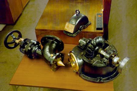
13 pressure rating of the pipe should be at least the static head converted to pressure plus a reasonable safety factor. Manufacturers of micro-hydro turbines The Pelton turbine is one of the designs that is suitable for this type of application. The following images show the products offered by two manufacturers Harris and Hydro Power. Harris offers a range of turbine generators between 700 and 2500 watts. Harris Hydroelectric is one manufacturer, see this web site Figure 7. Harris turbine. 13


14 Figure 8. Harris turbine view of the Pelton turbine wheel from below. Figure 9. Hydro Power turbine view of the Pelton turbine wheel from below. 14

15 Figure 10. Hydro Power installation. Figure 11.Turgo turbine. 15


16 Figure 12.Turgo water jet nozzle position vs. wheel. Figure 13. Turgo wheel. 16
17 Appendix A 17
18 Analysis of the graphs of Power vs. Pipe diameter The plots of power vs. pipe diameter are split into 4 graphs for systems that can be built with 100, 500, 1000 and 2000 feet of pipe. Single nozzles were used in the analysis and their diameter was optimized to give the maximum power for each static head and pipe size. The maximum nozzle diameter used was 1.5 inch. 18
19 Power vs. static head at various pipe dias. from 2" to 6" and 100 feet of pipe, single 1.5" dia. nozzle Power at turbine wheel (watts) Static Head (ft) 2" dia. 3" dia. 4" dia. 6" dia. Figure 14. Power vs. pipe diameter at feet of head and 100 feet of pipe. 19
20 Power vs. static head at various pipe dias. from 2" to 6" and 500 feet of pipe, single nozzle of varying size Power at turbine wheel (watts) " dia. 3" dia. 4" dia. 6" dia Static head (ft) Figure 15. Power vs. pipe diameter at feet of head and 500 feet of pipe. 20
21 Power vs. static head at various pipe dias. from 2" to 6" and 1000 feet of pipe, single nozzle of varying size Power at turbine wheel (watts) " dia. 3" dia. 4" dia. 6" dia Static head (ft) Figure 16. Power vs. pipe diameter at feet of head and 1000 feet of pipe. 21
22 Power vs. static head at various pipe dias. from 2" to 6" and 2000 feet of pipe, single nozzle of varying size Power at turbine wheel (watts) " dia. 3" dia. 4" dia. 6" dia. Static head (ft) Figure 17. Power vs. pipe diameter at feet of head and 2000 feet of pipe. 22
Micro Hydro Electric Generators
 Micro Hydro Electric Generators Harris Pelton Turbines ES and D Turgo Generators Pressure Drop in Pipe Flow Rate Through Various Nozzles We offer a variety of small hydroelectric generators that are designed
Peerless Pump Company Handbook of Engineering Data
 Peerless Pump Company Handbook of Engineering Data Brochure EM77 DEFINITION OF PUMP TERMS A.1 A line shaft vertical turbine pump is a vertical-shaft centrifugal or mixed-flow pump with rotating impeller
Types of Hydropower Facilities
 Types of Hydropower Facilities 1 Impoundment Hydropower- uses a dam to store water. Water may be released either to meet changing electricity needs or to maintain a constant water level. 2 Run-of-River
Appendix A. An Introduction to Steam Turbine Selection
 Operator s Guide to General Purpose Steam Turbines: An Overview of Operating Principles, Construction, Best Practices, and Troubleshooting. Robert X. Perez and David W. Lawhon. 2016 Scrivener Publishing
Intro to. Part 1: Systems Overview. Dan New
 Intro to Hydropower Part 1: Systems Overview Dan New 2004 Dan New Hydropower is based on simple concepts. Moving water turns a turbine, the turbine spins a generator, and electricity is produced. Many
Micro Hydroelectric Generator. AC output : 230V/415V/50HZ
 Model Water HEAD (meter) Micro Hydroelectric Generator AC output : 230V/415V/50HZ WATER FLOW (liters/second ) POWER (W) Inlet Pipe dia. (mm) Packing Size/cm LxWxH CEV-300W 12-14 From 3 to 5 300 50 30x26x35,
Pumps, Turbines, and Pipe Networks, part 2. Ch 11 Young
 Pumps, Turbines, and Pipe Networks, part 2 Ch 11 Young Pump and Turbine Dimensional Analysis (11.5 Young) Say we want to replace turbines on the Hoover Dam Want to have a good design Essentially impossible
Utilization of Water Flow in Existing Canal System for Power Generation through Flow Acceleration Using Converging Nozzles
 American Journal of Engineering Research (AJER) e-issn: 2320-0847 p-issn : 2320-0936 Volume-5, Issue-5, pp-115-123 www.ajer.org Research Paper Open Access Utilization of Water Flow in Existing Canal System
Fluid Mechanics. The Energy Equation [7] Dr. Mohammad N. Almasri
![Fluid Mechanics. The Energy Equation [7] Dr. Mohammad N. Almasri](/thumbs/77/76088370.jpg "Fluid Mechanics. The Energy Equation [7] Dr. Mohammad N. Almasri") 1 Fluid Mechanics The Energy Equation [7] Dr. Mohammad N. Almasri http://sites.google.com/site/mohammadnablus/home 2 Introduction There are various types of devices and components that are utilized in
1 Fluid Mechanics The Energy Equation [7] Dr. Mohammad N. Almasri http://sites.google.com/site/mohammadnablus/home 2 Introduction There are various types of devices and components that are utilized in
CRHT VII. Design and CFD analysis of Pico- hydro Turgo turbine. Paper no. CRHT17-11
 Proceedings of the International Symposium on Current Research in Hydraulic Turbines CRHT VII April 04, 2016, Turbine Testing Lab, Kathmandu University, Dhulikhel, Nepal Paper no. CRHT17-11 Design and
= Guide angle = angle between direction of jet and direction of motion of vane/bucket.
 GEC223: FLUID MECHANICS MODULE 4: HYDROPOWER SYSTEMS TOPIC: IMPULSE TURBINES-PELTON WHEEL DEPARTMENT OF CIVIL ENGINEERING, LANDMARK UNIVERSITY, KWARA STATE, NIGERIA CONSTRUCTION AND WORKING OF A PELTON
To: Aimee McClure, John Krueger From: Karl Vachuska, Shiven Advani, Pilar Gonzalez, Valerie Nehls Subject: Hydroelectric Generator Recommendation
 To: Aimee McClure, John Krueger From: Karl Vachuska, Shiven Advani, Pilar Gonzalez, Valerie Nehls Subject: Hydroelectric Generator Recommendation Date: 12/5/2016 Our group worked with Pierce Manufacturing
SHRI RAMSWAROOP MEMORIAL COLLEGE OF ENGG. & MANAGEMENT
 B.Tech. [SEM VI(ME-61,62,63 & 64)] QUIZ TEST-1 Q-1). A jet strikes a smooth curved vane moving in the same direction as the jet and the jet get reversed in the direction. Show that the maximum efficiency
Appendix 6: Choosing the Right Turbine
 Appendix 6: Choosing the Right Turbine A graphical representation of the power output of the hydro turbines in our product line is shown below. Once you have determined your site s head, flow, and your
HOLE CLEANING IN DIRECTIONAL WELLS
 HOLE CLEANING IN DIRECTIONAL WELLS 1 ❶ Welcome to this presentation about Hole Cleaning in Directional Wells. It has been prepared by Sedco Forex, to give you a better understanding of the cuttings-transport
6 Generator Testing Data Analysis
 RMS Voltage 6 Generator Testing Data Analysis 1. Using the generator equations below. 2. Insert your measured component values. 3. Create a spread sheet and plot the data. 4. How close is the calculated
Simulation of the Effect of Bucket Tip Angle on Bucket Splitter of a Pelton Turbine
 Research Paper American Journal of Engineering Research (AJER) e-issn : 2320-0847 p-issn : 2320-0936 Volume-03, Issue-11, pp-85-92 www.ajer.org Open Access Simulation of the Effect of Bucket Tip Angle
Chapter (2) Prepared by Dr. Assim Al-Daraje
 Prepared by Dr. Assim Al-Daraje") Chapter (2) Prepared by Dr. Assim Al-Daraje 1 INTRODUCTION The Pelton turbine is ideal for high-head and low-discharge situations. The number of jets in a turbine is usually one. However, where additional
Chapter (2) Prepared by Dr. Assim Al-Daraje 1 INTRODUCTION The Pelton turbine is ideal for high-head and low-discharge situations. The number of jets in a turbine is usually one. However, where additional
MAE 456 FINITE ELEMENT ANALYSIS Truss Buckling Analysis LAB INSTRUCTIONS LAB ASSIGNMENT 3. Lab Objectives. Lab Tasks
 MAE 456 FINITE ELEMENT ANALYSIS Truss Buckling Analysis LAB INSTRUCTIONS LAB ASSIGNMENT 3 Lab Objectives erform a FEA Eigenvalue buckling analysis of a simple column. erform a FEA Eigenvalue buckling analysis
HEAD TANK (FOREBAY TANK)
") HEAD TANK (FOREBAY TANK) Head-tank - Pond at the top of a penstock or pipeline; serves as final settling basin, maintains the required water level of penstock inlet and prevents foreign debris entering
HEAD TANK (FOREBAY TANK) Head-tank - Pond at the top of a penstock or pipeline; serves as final settling basin, maintains the required water level of penstock inlet and prevents foreign debris entering
Design and Development of Pico-hydro Generation System for Energy Storage Using Consuming Water Distributed to Houses
 Design and Development of Pico-hydro Generation System for Energy Storage Using Consuming Water Distributed to Houses H. Zainuddin, M. S. Yahaya, J. M. Lazi, M. F. M. Basar and Z. Ibrahim Abstract This
Design and Construction of a Mini Hydro Turbine Model
 American Journal of Modern Energy 2018; 4(1): 1-6 http://www.sciencepublishinggroup.com/j/ajme doi: 10.11648/j.ajme.20180401.11 ISSN: 2575-3908 (Print); ISSN: 2575-3797 (Online) Design and Construction
Water & Wastewater Operation: Pipe Systems, System Curves, & Pump Curves
 Water & Wastewater Operation: Pipe Systems, System Curves, & Pump Curves Matt Prosoli PumpsPlus Inc. 30 Years in Water & Wastewater BA in Marketing, Michigan State Univ. MWEA Maintenance Committee 30 years
Hydro Electric Power (Hydel Power)
") Operating Principle Hydro Electric Power (Hydel Power) Hydro-electric power is generated by the flow of water through turbine, turning the blades of the turbine. A generator shaft connected to this turbine
Operating Principle Hydro Electric Power (Hydel Power) Hydro-electric power is generated by the flow of water through turbine, turning the blades of the turbine. A generator shaft connected to this turbine
UNIT 5 HYDRAULIC MACHINES. Lecture-01
 1 UNIT 5 HYDRAULIC MACHINES Lecture-01 Turbines Hydraulic machines which convert hydraulic energy into mechanical energy. This mechanical energy is used to run electric generator which is directly coupled
Determining Optimal Discharge and Optimal Penstock Diameter in Water Turbines
 Utah State University DigitalCommons@USU International Symposium on Hydraulic Structures Jun 9th, 1:30 PM - 3:30 PM Determining Optimal Discharge and Optimal Penstock Diameter in Water Turbines Arturo
Code No: R Set No. 1
 Code No: R05310302 Set No. 1 III B.Tech I Semester Regular Examinations, November 2008 HYDRAULIC MACHINERY AND SYSTEMS ( Common to Mechanical Engineering and Automobile Engineering) Time: 3 hours Max Marks:
Contact the Jurisdictional Engineer for materials allowed by each jurisdiction.
 Design Manual Chapter 3 - Sanitary Sewers 3C - Facility Design 3C-1 Facility Design A. Capacity of Pipe Pipe sizes 15 inches and smaller should carry the peak flow at a depth of no more than 0.67 of the
Task 1 For Task 1, the outlet was set as a zero-gauge pressure outlet, which is the same outlet condition as the five smaller pipes.
 Jacob Schichtel Project 2 Page 1 of 9 Setup The geometry was created in ANSYS Design modeler as specified in the report instructions. A plane of symmetry was used to reduce the computation time and to
Calculate the Costs of Piping System Elements
 Calculate the Costs of Piping System Elements by Ray Hardee, Engineered Software, Inc. Last month s column described the process of creating an energy cost balance sheet for a piping system (see Figure
Irrigation Tech II HYDRAULIC TROUBLESHOOTING
 Irrigation Tech II HYDRAULIC TROUBLESHOOTING How much water & pressure is needed? 2 Water Flow http://www.irrigationtutorials.com 3 Water Pressure Pressure is the force that moves water through a pipe
Task 5. Christopher Mack Zack Kaldy MET 330 Fluid Mechanics November 8, Purpose
 Purpose Task 5 Christopher Mack Zack Kaldy MET 330 Fluid Mechanics November 8, 2015 For the fifth task of this project we are asked to specify the layout of the piping system, the material type and sizes
AALSO Summary of Formulas needed for Levels I, II and III.
 AALSO Summary of Formulas needed for Levels I, II and III. The information provided below is used in the math portion of the proficiency exams. Please take time to review and learn how to use these formulas
Hydroelectric power plants
 Hydroelectric power plants Hydroelectric power plants can drive from a water stream or accumulation reservoir. Run-of-river hydroelectric plants (those without accumulation reservoirs) built along a river
T.E. (Mech., Mech. S/W) (Semester II) Examination, 2011 TURBOMACHINES (New) (2008 Pattern)
 (Semester II) Examination, 2011 TURBOMACHINES (New) (2008 Pattern)") *4063218* [4063] 218 T.E. (Mech., Mech. S/W) (Semester II) Examination, 2011 TURBOMACHINES (New) (2008 Pattern) Time : 3 Hours Marks : 100 Instructions : 1) Answer any three questions from each Section.
*4063218* [4063] 218 T.E. (Mech., Mech. S/W) (Semester II) Examination, 2011 TURBOMACHINES (New) (2008 Pattern) Time : 3 Hours Marks : 100 Instructions : 1) Answer any three questions from each Section.
Sump Pumps Office procedures for the Drainage & Grading section
 County of Los Angeles Department of Public Works Building and Safety Division Grading and Drainage Section Sump Pumps Office procedures for the Drainage & Grading section Introduction This manual provides
DESIGN OF A PELTON WHEEL TURBINE FOR A MICRO HYDRO POWER PLANT
 DESIGN OF A PELTON WHEEL TURBINE FOR A MICRO HYDRO POWER PLANT Manjunatha N 1, Kuldeepak Kumar 2, Dr. Thammaih Gowda 3 1, 2 Assistant Professor, Dept. of Mechanical Engineering, N.D.R.K.I.T, Hassan, Karnataka
FINAL Examination Paper (COVER PAGE) Programme : Diploma in Mechanical Engineering. Time : 8.00 am am Reading Time : 10 Minutes
 Programme : Diploma in Mechanical Engineering. Time : 8.00 am am Reading Time : 10 Minutes") Session : May 2013 FINAL Examination Paper (COVER PAGE) Programme : Diploma in Mechanical Engineering Course : EGR2180 : FLUIDS MECHANICS 2 Date of Examination : July 25, 2013 Time : 8.00 am 10.10 am Reading
Session : May 2013 FINAL Examination Paper (COVER PAGE) Programme : Diploma in Mechanical Engineering Course : EGR2180 : FLUIDS MECHANICS 2 Date of Examination : July 25, 2013 Time : 8.00 am 10.10 am Reading
Water and wastewater treatment operations
 The Search for Energy Savings: Optimization of Existing & New Pumping Stations Chris Reinbold and Vincent Hart Water and wastewater treatment operations account for 30 to 50 percent of all municipal power
Level 6 Graduate Diploma in Engineering Hydraulics and hydrology
 910-103 Level 6 Graduate Diploma in Engineering Hydraulics and hydrology Sample Paper You should have the following for this examination one answer book ordinary graph paper pen, pencil, ruler Work sheet
Micro Hydro In a Municipal Water and Power System
 Micro Hydro In a Municipal Water and Power System By: Chris Thompson Colorado Springs Utilities Hydro Electric Power Plant Operator and Micro Hydro Consultant Presented at: The 2006 APPA Engineering and
5555ter supply the Eugene Mill Race is a costly task that may have alternatives not explored by its
 Scdr45555555555555555555555555555555555555555555555555555555555555555555555555555555 5555ter supply the Eugene Mill Race is a costly task that may have alternatives not explored by its proprietor. The
Renewable and Alternative Energies
 Department of Electrical and Energy Engineering This work is published under a license: Creative Commons BY-NC-SA 4.0 Contents Topic 1. Wind energy. Topic 2. Solar energy. Topic 3. Ocean energy.. Topic
Hybrid Hydroelectric Power Plant : The Ultimate Technology For Electricity Generation
 Hybrid Hydroelectric Power Plant : The Ultimate Technology For Electricity Generation Prof. Nilesh P. Patil. 1*, Prof. Dr. V. S. Patil. 2 1 - Asst. Professor (Chemical Engineering), University Institute
IMPACT AND PUNCTURING OF JARI TUNNEL AND ENLARGEMENT OF EXISTING TAPPINGS FOR ADDITIONAL WATER SUPPLY AND POWER GENERATION
 117 Paper No. 738 IMPACT AND PUNCTURING OF JARI TUNNEL AND ENLARGEMENT OF EXISTING TAPPINGS FOR ADDITIONAL WATER SUPPLY AND POWER GENERATION JAVED MUNIR, SYED ABBAS ALI, IRFAN MAHMOOD 118 Javed Munir,
University Curriculum Development for Decentralized Wastewater Management
 Page i University Curriculum Development for Decentralized Wastewater Management Module Text Paul Trotta, P.E., Ph.D. Justin Ramsey, P.E. Chad Cooper September 004 Page ii NDWRCDP Disclaimer This work
CHAPTER 5 MASS AND ENERGY ANALYSIS OF CONTROL VOLUMES
 Thermodynamics: An Engineering Approach 8th Edition in SI Units Yunus A. Ç engel, Michael A. Boles McGraw-Hill, 2015 CHAPTER 5 MASS AND ENERGY ANALYSIS OF CONTROL VOLUMES Objectives Develop the conservation
Turbo Machines Pumps and Turbines ME 268
 Turbo Machines Pumps and Turbines ME 268 Turbo Machines Turbo machines are dynamic fluid machines that either extract energy from a fluid (turbine) or add energy to a fluid (pump) as a result of dynamic
Irrigation Application Calibration Methods
 CHAPTER 6 Irrigation Application Calibration Methods Bryan Smith and John P. Chastain In order to apply animal manures and lagoon effluents properly the systems used must first be calibrated. This calibration
hydro-electric turbine
 hydro-electric turbine BUYER S GUIDE by Ken Gardner & Ian Woofenden Co-author Ian Woofenden holds a 4-inch pitch diameter Pelton runner while standing in front of an 96-inch pitch diameter Pelton runner
Chapter 8 Fatigue Strength and Endurance
 Chapter 8 Fatigue Strength and Endurance Screen Titles Fatigue Failure Process 1, 2 Fatigue Strength Testing S-N Diagram Fatigue Strength Equation 1, 2 Endurance Limit Behavior Endurance Limit Equations
TECHNICAL MANUAL TEH-375A. Pump & System Curve Data for Centrifugal Pump Selection and Application
 TECHNICAL MANUAL TEH-375A Pump & System Curve Data for Centrifugal Pump Selection and Application TABLE OF CONTENTS Introduction... 3 Developing the Pump Curve... 3 Effect of Viscosity on the Pump Curve...
3. Design of Generation Equipment. 3.1 Turbine (1) Turbine Types Turbines are classified into two types according to their water energy utility:
 Turbine Types Turbines are classified into two types according to their water energy utility:") 3. Design of Generation Equipment 3.1 Turbine (1) Turbine Types Turbines are classified into two types according to their water energy utility: Impulse Turbines: all available water energy is converted
3. Design of Generation Equipment 3.1 Turbine (1) Turbine Types Turbines are classified into two types according to their water energy utility: Impulse Turbines: all available water energy is converted
Lab 6 - Pumping Test. Pumping Test. Laboratory 6 HWR 431/
 Pumping Test Laboratory 6 HWR 431/531 7-1 Introduction: Aquifer tests are performed to evaluate the capacity of an aquifer to meet municipal or industrial water requirements. Hydraulic characteristics
Tile Drainage Pump Stations
 AE1747 Tile Drainage Pump Stations for Farm Fields Tom Scherer Agricultural Engineer and Associate Professor (NDSU photos) North Dakota State University Fargo, North Dakota April 2015 Contents Need for
AALSO Proficiency Program Level I, II & III
 AALSO Proficiency Program Level I, II & III Hello, and welcome to AALSO s 2010 Proficiency Program! AALSO offers a multi-level operator competency acknowledgment program based on test scores received from
6) Penstocks 3.25m dia and 965m long to lead a design discharge of cumecs
 Penstocks 3.25m dia and 965m long to lead a design discharge of cumecs") Project: Sorang Hydro Electric Project - 100 MW Overview: M/s.Himachal Sorang Pvt.Ltd., Hyderabad, is developing the Run of the River Sorang Hydro Electric Project (100MW) in Kinnaur District of Himachal
Project: Sorang Hydro Electric Project - 100 MW Overview: M/s.Himachal Sorang Pvt.Ltd., Hyderabad, is developing the Run of the River Sorang Hydro Electric Project (100MW) in Kinnaur District of Himachal
storage There are three basic systems for storing liquid SYSTEM DESCRIPTIONS
 There are three basic systems for storing liquid manure: formed tanks, earthen basins, and lagoons. The type of storage affects the manure volume, the nutrient concentration, and ultimately, the land application
AR No. # Efficient Irrigation
 AR No. # Efficient Irrigation Recommendation Optimize the facilities irrigation pumping system by ensuring pumps are operating at their Best Efficiency Point (BEP). We estimate the system pumping efficiency
Size Matters: Picking the Right Size of Piping System Components. April 13, 2017
 Size Matters: Picking the Right Size of Piping System Components April 13, 2017 Did You Know? Pump systems account for ~25% of electric motor energy consumption and 20 60% of total electrical energy usage
Water Resources Engineering. Prof. R. Srivastava. Department of Water Resources Engineering. Indian Institute of Technology, Kanpur.
 Water Resources Engineering Prof. R. Srivastava Department of Water Resources Engineering Indian Institute of Technology, Kanpur Lecture # 13 Today we will continue to discuss some of the abstractions
MATHEMATICS FOR WATER OPERATORS
 MATHEMATICS FOR WATER OPERATORS Mathematics The understanding of the mathematics of water hydraulics (flows, pressures, volumes, horsepower, velocities) and water treatment (detention time, chemical dosage)
CE2253 APPLIED HYDRAULIC ENGINEERING (FOR IV - SEMESTER)
") CE2253 APPLIED HYDRAULIC ENGINEERING (FOR IV - SEMESTER) UNIT I to V QUESTION BANK Prepared by, M.SUGANYA. B.E., LECTURER / CIVIL DEPARTMENT OF CIVIL ENGINEERING CE2253 APPLIED HYDRAULIC ENGINEERING UNIT
CE2253 APPLIED HYDRAULIC ENGINEERING (FOR IV - SEMESTER) UNIT I to V QUESTION BANK Prepared by, M.SUGANYA. B.E., LECTURER / CIVIL DEPARTMENT OF CIVIL ENGINEERING CE2253 APPLIED HYDRAULIC ENGINEERING UNIT
Energy Resources. Assosciate Professor
 Energy Resources Dr. Fahad Noor Assosciate Professor f.noor@uet.edu.pk Engr. Adnan Qamar Lecturer adnan@uet.edu.pk Hydro Power Hydropower energy is ultimately derived from the sun, which drives the water
International Journal of Scientific and Research Publications, Volume 8, Issue 8, August ISSN
 International Journal of Scientific and Research Publications, Volume 8, Issue 8, August 2018 314 Flow Analysis of Turgo Impulse Turbine for Low Head Power Plant Hnin Hnin Ei *, Myat Myat Soe ** * Department
Pumped Outlets for Drainage Systems
 ' OCT,,,80 t!) _ jilibrary (446: L UN I VERSTP 4;4 Pumped Outlets for Drainage Systems Special Report 601 September 1980 Oregon State University Extension Service Pumped Outlets for Drainage Systems by
Pumps, Turbines, and Pipe Networks. Ch 11 Young
 Pumps, Turbines, and Pipe Networks Ch 11 Young Chapter Topics Types of pumps and turbines Moment of momentum review Pump and turbine theory Energy and power Pump selection Pump-pipe networks Use of pipe
WinTR-55 Small Watershed Hydrology
 WinTR-55 Small Watershed Hydrology Intermediate WinTR-55 Training Modeling Watersheds with Structures SEE NOTES AT CLASS EXERCISE #4. 1 Course Outline Overview Review of Hydrology Terms Modeling Single
TYPICAL INSTALLATION INSTRUCTIONS
 TYPICAL INSTALLATION INSTRUCTIONS Environment One Grinder Pump Feature Identification 1. Grinder Pump Basin High density polyethylene (HDPE) 2. Accessway Cover Painted Steel 3. Electrical Quick Disconnect
Performance Testing of The Robert Moses Niagara Power Plant and Sir Adam Beck Generating Station
 Performance Testing of The Robert Moses Niagara Power Plant and Sir Adam Beck Generating Station By Albert F. Mikhail, P.Eng., Ontario Power Generation and Robert J. Knowlton, P.E., New York Power Authority
EXAMPLE SHEET FOR TOPIC 2 AUTUMN Q1. What is the significance of the Reynolds number Re for the flow of fluid in a circular pipe?
 EXMPLE SHEET FOR TOPI 2 UTUMN 2013 Q1. What is the significance of the Reynolds number Re for the flow of fluid in a circular pipe? If the friction factor for a pipe is given by λ = 64/Re for laminar flow,
PV Systems IV EE 446/646
 PV Systems IV EE 446/646 PV-Powered water pumping One of the most economically viable photovoltaic applications today is water pumping in remote areas. A simple PV system can raise water from a well or
Draft INTRODUCTION X-1 PUMP APPLICATIONS X-1 PUMP TANKS X-4 PUMP TYPES X-8 PUMP CONTROLS X-8. Draft
 Draft INTRODUCTION X-1 PUMP APPLICATIONS X-1 PUMP TANKS X-4 PUMP TYPES X-8 PUMP CONTROLS X-8 Draft PUMP PRESSURE AND FLOW X-11 PUMP DISCHARGE CURVE X-12 SELECT THE PUMP FOR THE APPLICATION X-15 ENERGY
Appendix J Effluent Pump Station
 Appendix J Effluent Pump Station TECHNICAL MEMORANDUM Salmon Creek Treatment Plant Effluent Pump Station Hydraulics and Phasing Analysis for the Phase 5A Project Columbia River Outfall and Effluent Pipeline
AN EXPERIENCE IN THERMODYNAMIC TEST OF LOW HEAD TURBINE IN THAILAND THE CASE OF MAE NGAT HYDRO POWER PLANT
 AN EXPERIENCE IN THERMODYNAMIC TEST OF LOW HEAD TURBINE IN THAILAND THE CASE OF MAE NGAT HYDRO POWER PLANT Matha Tantaworranart Performance Test Engineer at Hydro Power Plant Performance Test Section,
2 FINDING OF THE POTENTIAL SITES
 EXECUTIVE SUMMARY 1 Background S-1 2 User of Manual S-1 3 Applicable Range of Micro-hydro power in the Indonesia S-2 4 How to use this Manual S-2 Chapter 1 INTRODUCTION 1-1 1.1 Purpose of the Manual
FLEMING HILL WTP FINISHED WATER PUMP STATION ELECTRIFICATION PROJECT TECHNICAL MEMORANDUM NO. 1 HYDRAULIC ANALYSIS AND PUMP SELECTION
 CITY OF VALLEJO This document is released for the purpose of information exchange review and planning only under the authority of George C. Chin, October 15, 2015, State of California, PE No. 82654. FLEMING
Experimental Investigation on Effect of Head and Bucket Splitter Angle on the Power Output of A Pelton Turbine
 Experimental Investigation on Effect of Head and Bucket Splitter Angle on the Power Output of A Pelton Turbine Chukwuneke J. L. Achebe C. H. Okolie P. C. Okwudibe H. A. Mechanical Engineering Department,
Volume method Volume being used Time required to fill. Weir Method Width of slot in weir Height of water above slot
 Micro Hydro Survey Basic Considerations Understanding how much power you need will make designing your micro hydro project much easier. Start by filling out the Energy Budget spreadsheet to determine your
Chapter 5 MASS AND ENERGY ANALYSIS OF CONTROL VOLUMES
 Thermodynamics: An Engineering Approach Seventh Edition in SI Units Yunus A. Cengel, Michael A. Boles McGraw-Hill, 2011 Chapter 5 MASS AND ENERGY ANALYSIS OF CONTROL VOLUMES Copyright The McGraw-Hill Companies,
Pelton Wheels. By: Chris Holmes, Amanda Higley, and Nick Hiseler
 Pelton Wheels By: Chris Holmes, Amanda Higley, and Nick Hiseler History Lester Allan Pelton invented the Pelton wheel, an impulse type water turbine in the late 1870 s. Pelton's invention started from
Honeywell Thermal Solutions. Engineering Guide
 Engineering Guide Honeywell Thermal Solutions Engineering Guide Copyright 2017 by Honeywell Thermal Solutions All Rights Reserved CONTENTS 1. Orifices & Flows Coefficients of Discharge for Various Types
UNIT I: UNIFORM FLOW PART B
 UNIT I: UNIFORM FLOW PART-A 1 Define open channel flow with example BT-1-1 2 Distinguish between open channel flow and pipe flow. BT-4-1 3 Compute the hydraulic mean depth of a small channel 1m wide, 0.5m
Low Pressure Drip/Micro System Design Analysis of Potential Rebate
 Low Pressure Drip/Micro System Design Analysis of Potential Rebate Prepared by: Dr. Charles Burt, ITRC Dr. Dan Howes, ITRC Drip/micro irrigation systems are often referred to as low pressure systems because
A dimensional analysis for determining optimal discharge and penstock diameter in impulse and reaction water turbines
 A dimensional analysis for determining optimal discharge and penstock diameter in impulse and reaction water turbines Arturo S. Leon (Corresponding author). School of Civil and Construction Engineering,
 DEPARTMENT OF CIVIL ENGINEERING CE6403/ APPLIED HYDRAULIC ENGINEERING QUESTION BANK TWO MARKS UNIT I UNIFORM FLOW 1. Differentiate open channel flow from pipe flow. 2. What is specific energy and is the
Alpha College of Engineering
 Alpha College of Engineering Department of Mechanical Engineering TURBO MACHINE (10ME56) QUESTION BANK PART-A UNIT-1 1. Define a turbomahcine. Write a schematic diagram showing principal parts of a turbo
Chapter 10. Pipeline Installation
 Chapter 10 CHAPTER 10 STOCKWATER PIPELINE INSTALLATION TABLE OF CONTENTS PART 10.1 TRENCHING 10-1 10.1.1 Backhoe Constructed Trench 10-1 10.1.2 Trencher Constructed Trench 10-1 10.1.3 Backfilling and Maintenance
Index. outlet protection Rev. 12/93
 6 Index outlet protection level spreader outlet stabilization structure 6.40.1 6.41.1 Rev. 12/93 Practice Standards and Specifications 6.40 level spreader Definition Purpose Conditions Where Practice Applies
Irrigation Rehabilitation Program Design and Construction Standards
 Irrigation Rehabilitation Program Design and Construction Standards Prepared by the IRP Standards Review Committee For Alberta Agriculture and Rural Development, Irrigation Secretariat April 26, 2010 Adopted
(a) the inlet and exit vane angles, (b) work done (c) Efficiency of the system. [16]
![(a) the inlet and exit vane angles, (b) work done (c) Efficiency of the system. [16]](/thumbs/81/82633878.jpg "(a) the inlet and exit vane angles, (b) work done (c) Efficiency of the system. [16]") Code No: R05310302 Set No. 1 III B.Tech I Semester Regular Examinations, November 2007 HYDRAULIC MACHINERY AND SYSTEMS ( Common to Mechanical Engineering and Automobile Engineering) Time: 3 hours Max Marks:
Code No: R05310302 Set No. 1 III B.Tech I Semester Regular Examinations, November 2007 HYDRAULIC MACHINERY AND SYSTEMS ( Common to Mechanical Engineering and Automobile Engineering) Time: 3 hours Max Marks:
2. (a) How do you classify water turbines? (b) Define and explain different efficiencies of a water turbine. [8+8]
![2. (a) How do you classify water turbines? (b) Define and explain different efficiencies of a water turbine. [8+8]](/thumbs/83/87300886.jpg "2. (a) How do you classify water turbines? (b) Define and explain different efficiencies of a water turbine. [8+8]") Code No: RR310302 Set No. 1 III B.Tech I Semester Supplementary Examinations, February 2007 HYDRAULIC MACHINERY AND SYSTEMS ( Common to Mechanical Engineering and Automobile Engineering) Time: 3 hours
Code No: RR310302 Set No. 1 III B.Tech I Semester Supplementary Examinations, February 2007 HYDRAULIC MACHINERY AND SYSTEMS ( Common to Mechanical Engineering and Automobile Engineering) Time: 3 hours
Energy Requirements for Drip Irrigation of Tomatoes in North Florida 1
 BUL289 Energy Requirements for Drip Irrigation of Tomatoes in North Florida 1 A.G. Smajstrla, B.F. Castro and G.A. Clark 2 INTRODUCTION The energy required to pump irrigation water for crop production
Chapter 5 MASS AND ENERGY ANALYSIS OF CONTROL VOLUMES
 Thermodynamics: An Engineering Approach Seventh Edition in SI Units Yunus A. Cengel, Michael A. Boles McGraw-Hill, 2011 Chapter 5 MASS AND ENERGY ANALYSIS OF CONTROL VOLUMES Mehmet Kanoglu University of
CHAPTER 2: Pressure piped irrigation techniques
 Pressurized Irrigation Techniques 2.1 CHAPTER 2: Pressure piped irrigation techniques PRESSURE PIPED IRRIGATION SYSTEMS A pressure piped irrigation system is a network installation consisting of pipes,
Building Hydronic Systems Pressure Profile
 Building Hydronic Systems Pressure Profile For HVAC Project Managers Fachgesprach 6-B WTF Institute of Higher Learning Part -2 Actual Building Pressure Profile 1 All Results Rounded To Whole Number In
Effluent Conveyance. Paul Trotta, P.E., Ph.D. Justin Ramsey, P.E. Chad Cooper
 Effluent Conveyance Paul Trotta, P.E., Ph.D. Justin Ramsey, P.E. Chad Cooper University Curriculum Development for Decentralized Wastewater Management 1 NDWRCDP Disclaimer This work was supported by the
EXPERIMENTAL AERODYNAMICS FLOW TROUGH AN ORIFICE LAB SHEET
 EXPERIMENTAL AERODYNAMICS FLOW TROUGH AN ORIFICE LAB SHEET EMRE KOÇ ONUR GÜNEL 1- Introduction When a fluid passes through a constriction, such as through a sharp-edged hole or over a weir, the constriction
M E 320 Professor John M. Cimbala Lecture 24
 M E 30 Professor John M. Cimbala Lecture 4 Today, we will: Discuss pump performance curves Discuss how to match a pump and a piping system, and do some example problems. Pump Performance a. Pump performance