Gas Dehydration. Chapter 11 Based on presentation by Prof. Art Kidnay
|
|
|
- Sharon Higgins
- 6 years ago
- Views:
Transcription


1 Gas Dehydration Chapter 11 Based on presentation by Prof. Art Kidnay
2 Plant Block Schematic 2
3 Reasons for Gas Dehydration Field Operations Prevent hydrate formation Minimize corrosion Need to dry gas to dew point below lowest operating temperature Plant Operations Need 4 to 7 lb/mmscf (85 to 150 ppmv) in pipeline Glycol dehydration most common to produce water contents down to 10 ppmv Need to have less than 1 ppmv H 2 O in gas to cryogenc units Glycol dehydration cannot get to these low water levels mole sieves used for this service 3
4 Topics Water Content of Hydrocarbons Gas Dehydration Processes Absorption processes Adsorption processes Non regenerable desiccant processes Membrane processes Other processes Comparison of dehydration processes Safety and Environmental Considerations 4
5 Water Content of Hydrocarbons
6 Equilibrium considerations Equal fugacities for each component in each phase. Between gas & water phases: vap P il, ip i vil, yi xk i i where Ki exp dp iv, iv, P sat RT P i For a gas in contact with pure water: y H2O P P vap H2O since x 1 H2O Formation of the water phase will control the water content in the gas phase Increasing water in the feed increases the amount of free water, not the concentration of water in the gas. Can decrease the gas water content by adding compounds that are water soluble 6

7 Water content of natural gas Based on typical gas composition Separate corrections for actual composition & acid gas content Takes into account non-idealities Take care if gas is specified as wet or dry basis dry basis does not include the amount of water in the MMscf N / M Wet Basis: X y / M Dry Basis: H2O H2O H2O H2O H2O NHC NH2O X H2O N / M y / M N 1 y H2O H2O H2O H2O When less than 5,000 lb/mmscf the wet & dry values are within 0.5% HC H2O Fig. 20-4, GPSA Engineering Data Book, 13 th ed. Figure 11.1 in Kidnay et. al. text book 7


8 Water content of natural gas typical pipeline specs GPSA Engineering Data Book, 13 th ed. 8
 & (c) in Kidnay et. al.")
9 Water content of natural gas GPSA Engineering Data Book, 13 th ed. Figure 11.1 (b) & (c) in Kidnay et. al. text book 9
10 Applicability of dehydration processes 10
11 Dehydration by Absorption
12 Equilibrium considerations Glycols tend to be only in the water phase (i.e., non-volatile & very low solubility in the hydrocarbon liquid phase) For a gas in contact with water/glycol mixture: y H2O x H2O P P vap H2O Water content in the gas phase is less than that for a pure water phase since x H2O < 1 Away from glycol, must reduce temperature to create a free water phase. 12
13 Typical Glycols Name EG DEG TEG Ethylene Glycol Diethylene Glycol Triethylene Glycol Formula C 2 H 6 O 2 C 4 H 10 O 3 C 6 H 14 O 4 Molecular Weight Boiling Point ( F) Vapor 77 F (mmhg) 0.12 < 0.01 < F (lb/gal) F (cp) Decomposition temperature ( F) Fig , GPSA Engineering Data Book, 13 th ed. 13


14 Glycol molecular structure Ethylene glycol HO-CH 2 -CH 2 -OH Diethylene Glycol HO-CH 2 -CH 2 -O-CH 2 -CH 2 -OH Triethylene Glycol HO-CH 2 -CH 2 -O-CH 2 -CH 2 -O-CH 2 -CH 2 -OH Chemical structures drawn using 14
15 Equilibrium water content above TEG solutions Based on Fig GPSA Data Book 13 th ed. & Figure 11.3 in Kidnay et. al. text book Based on 1,000 psia contactor pressure 15
16 Example Equilibrium water content above TEG solutions Operate a TEG 100 o F & 1,000 psia with 99.9 wt% TEG introduced at the top Dried gas is protected to a dew point of -40 o F Fig , GPSA Engineering Data Book, 13 th ed. Figure 11.3 in text book 16
17 Equilibrium water content for TEG solutions 17
18 Typical Glycol Dehydration Unit System 2 5 gal TEG per lb water removed Absorber / Contactor o F inlet Can operate up to 2,000 psia Typically 4 10 bubble cap trays 25 30% efficiency 5 10 psi pressure drop Flash tank minute residence time 150 o F, psig Regenerator Packed equivalent to 3 4 trays o F Fig , GPSA Engineering Data Book, 13 th ed. Basis for Figure 11.2 in text book 18
19 Typical Glycol Dehydration Unit System 2 5 gal TEG per lb water removed Absorber / Contactor o F inlet Can operate up to 2,000 psia Typically 4 10 bubble cap trays 25 30% efficiency 5 10 psi pressure drop Flash tank minute residence time 150 o F, psig Regenerator Packed equivalent to 3 4 trays o F y P x P H2O vap H2O H2O 19
20 Example based on GPSA Data Book example MMscfd of a 0.65 gravity natural gas enters a TEG contactor at 600 psia and 100 o F. The outlet water content specification is 7 lb H2O/MMscf and the TEG circulation rate is 28 lb TEG/ lb H2O absorbed (3 gal TEG/lb H2O). How much water is to be absorbed? What is the rich TEG concentration? What is the lean TEG concentration? Water content at inlet conditions? 70 lb/mmscf How much water is removed? lb H2O lb TEG day lb H2O lb TEG day 20
. How much water is to be absorbed?")
21 Example based on GPSA Data Book example MMscfd of a 0.65 gravity natural gas enters a TEG contactor at 600 psia and 100 o F. The outlet water content specification is 7 lb H2O/MMscf and the TEG circulation rate is 28 lb TEG/ lb H2O absorbed (3 gal TEG/lb H2O). How much water is to be absorbed? What is the rich TEG concentration? What is the lean TEG concentration? How much TEG is circulated? lb H2O lb TEG day lb H2O lb TEG day lb H2O gal TEG day lb H2O hr min day hr gal TEG 3.9 min 21
. How much water is to be absorbed?")
22 Example based on GPSA Data Book example (#2) 30 MMscfd of a 0.65 gravity natural gas enters a TEG contactor at 600 psia and 100 o F. The outlet water content specification is 7 lb H2O/MMscf and the TEG circulation rate is 28 lb TEG/ lb H2O absorbed (3 gal TEG/lb H2O). How much water is to be absorbed? What is the rich TEG concentration? What is the lean TEG concentration? Dew point temperature at the contactor pressure (600 psia)? ~ 24 o F 22
23 Example based on GPSA Data Book example (#3) 30 MMscfd of a 0.65 gravity natural gas enters a TEG contactor at 600 psia and 100 o F. The outlet water content specification is 7 lb H2O/MMscf and the TEG circulation rate is 28 lb TEG/ lb H2O absorbed (3 gal TEG/lb H2O). How much water is to be absorbed? What is the rich TEG concentration? What is the lean TEG concentration? What is the minimum TEG concentration for a 24 o F dew point & the contactor temperature (100 o F)? ~98.5 wt% Lean TEG has 806 lb/day water Rich TEG content (after absorbing the water from the wet gas) lb TEG day lb H2O lb TEG day day 95.2 wt% H2O 23
24 Solubility of hydrocarbons in glycol solutions GPSA Engineering Data Book, 13 th ed. Methods to control BTEX emissions from Regenerator Condense overhead & recover Burn vent gas through flare or thermal oxidizer Recycle back to process 24

25 Field Glycol Dehydrator stripper contactor reboiler glycol pump Inlet separator gas burner heat exchanger, surge tank Flash separator 3-phase, gas,glycol,condensate From Sivalls, Glycol Dehydration Design, LRGCC,
26 Common Operational Problems Contactor foaming Contaminates: hydrocarbons, salts, particulates, inhibitors, O 2 Poor dehydration (from source other than foaming) Gas rate too low - 80% flow reduction = 20 % tray eff Glycol rate low - 75% flow reduction = 33% tray eff Glycol inlet temperature too high Flash drum / Foaming in Still Presence of heavy hydrocarbons 26
27 Dehydration by Adsorption

28 Absorption vs Adsorption Absorption Adsorption 28

29 Physical absorption 29
30 Adsorption fundamentals Two types of adsorption Chemisorption Chemical interaction between adsorbate and adsorbent May not be completely reversible Physical adsorption Only physical interaction between adsorbate and adsorbent Completely reversible -ΔH Chem >> -ΔH Phys 30
31 Physical Adsorption Fundamentals Factors affecting selectivity Size adsorbent pore diameter major factor Volatility less volatile displaces more volatile (e.g., C 3 displaces C 2 ) Polarity For desiccants, more polar displaces less polar (e.g., CO 2 displaces C 2, MeOH displaces CO 2, water displaces MeOH) 31
32 Adsorption Isotherms Lb Water Adsorbed / 100 lb Activated Adsorbent From UOP 32
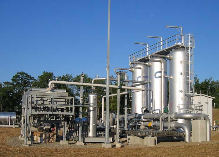
33 Solid Desiccant Dehydrator Twin Tower System Fig , GPSA Engineering Data Book, 13 th ed. 33


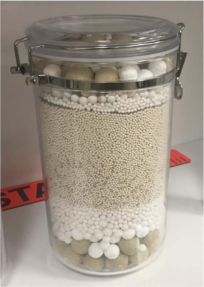
34 Typical Vessel Loading Sample packing of catalyst/dessicant on top of supports Model prepared by Enterprise Products Possible configuration for drying 100 MMscfd to a dew point of -150ºF, adsorption time ~12 hours
35 Concentration Profile Equilibrium Zone (Saturated) Mass Transfer Zone (Partially saturated) Active Zone (Unsaturated) 35
36 Concentration Profile y In y Out 36
37 Regenerating Bed Temperature History Heat On Inlet Temperature Outlet Temperature Desorption Bed Heating Bed Cooling Time, Hours
38 Regenerating Bed Temperature History Heat On Inlet Temperature 250 Temperature, ºF Outlet Temperature Temperature, ºC Desorption Bed Heating Bed Cooling Time, Hours 38
39 Common Adsorbents for Drying In order of increasing cost: Silica gel (SiO 2 ) Min exit water content 10 to 20 ppmv (~-60 o F) Inert and used for inlet concentrations of > 1 mol% Activated Alumina (Al 2 O 3 ) Min exit water content 5 to 10 ppmv (~-100 o F) High mechanical strength but more reactive Molecular Sieve (4A and 3A) Min exit water content below 0.1 ppmv (~-150 o F) Highest surface area Composite of sieve and clay binder 39
40 Design steps Determine size of vessels for adsorption Determine the bed diameter based on superficial gas velocity / allowable pressure drop Too small pressure drop will be too high & can damage the sieve Too large need too high a regeneration gas rate to prevent channeling Typically use (-P/L) < 0.33 psi/ft with a total pressure drop of 5 8 psi max Choose an adsorption period & calculate the mass of desiccant Sets the bed height contributions from saturation zone & mass transfer zone heights 8 to 12 hour periods with 2 or 3 beds are common Regeneration o Too long more desiccant & larger vessels needed than necessary o Too short a time shorter desiccant life Calculate heat required to desorb water while also heating the desiccant & vessel Total amount of regeneration gas flow calculated based on heating phase about 50-60% of total regeneration time Regeneration gas flowrate should give a pressure drop gradient of at least 0.01 psi/ft 40
![Design equations (#1) Determine gas velocity for bed diameter Modified Ergun equation for pressure drop P B V C V L 2 Viscosity [cp] & density [lb/ft³] determined at inlet conditions Solve quadratic](/docs-images/75/72708541/images/41-0.jpg "equation for maximum superficial velocity (V max [ft/min]) for 0.")
41 Design equations (#1) Determine gas velocity for bed diameter Modified Ergun equation for pressure drop P B V C V L 2 Viscosity [cp] & density [lb/ft³] determined at inlet conditions Solve quadratic equation for maximum superficial velocity (V max [ft/min]) for 0.33 psi/ft pressure drop Pressure drop gradient in units of psi/ft Minimum diameter D min 4 m V max Adjust diameter upwards to nearest ½ foot increment Recalculate superficial linear velocity & pressure drop using adjusted diameter 41
42 Design equations (#2) Determine bed length (method 1) Amount of desiccant in saturation zone S m 4 S L 0.13 SS T water sat sat sat 2 C C D bulk Assumes 13 lb water per 100 lb dessicant Amount of desiccant in the mass transfer zone (MTZ) (GPSA EDB method) C ln %sat SS L MTZ ft V ft/min C Z where C Z is 1.70 ft for 1/8 inch sieve & 0.85 for 1/16 inch sieve or Trent method for MTZ L MTZ ft V ft/min C F T 42
43 Design equations (#3) Determine bed length (method 2) Calculate effective desiccant capacity which includes the MTZ effect, temperature, and relative humidity corrections. An effective capacity of 8 10% is typically assumed. S m 4 S L water bed bed bed 2 Ceff D bulk Finalize bed length Total bed height (L sat +L MTZ or L bed ) but should not be less than the bed diameter or 6 ft, whichever is greater Total bed pressure drop should be 5 8 psi max If too large increase the bed diameter Determine vessel height & weight Total bed height plus other allowances at least 3 ft (for inlet distributor on top and bed support & hold down balls underneath) 43
44 Design equations (#4) Regeneration calculations Used to determine the required regeneration gas flow & the fuel gas requirements If regeneration gas recycled back to inlet of mole sieves then you must add this rate to that of the feed gas for the bed calculations Heat loads Heat to desorb water increase water to its desorption temperature, break adherence to surface, & vaporize o Use 1,800 Btu/lb water adsorbed for conservative design Heat to increase sieve to regeneration temperature Heat to increase vessel to regeneration temperature Heat losses typically estimated as 10% 44
45 Design equations (#5) Regeneration Calculations (cont.) Calculation of vessel weight for heating calculations 12 DPdesign tin and msteel lb155t 0.125Lvessel 0.75 D D P design where the 0.75D term accounts for the weight of the vessel heads Design pressure in psig. Usually 10% greater than operating pressure (minimum 50 psig) Usually have to heat the regeneration gas 50 o F hotter than the desired regeneration temperature (e.g., 500 o F gas needed to regenerate at 450 o F) Total regeneration load 2.5 times the minimum load Assumes only 40% of the heat is transferred from gas to mole sieve system. The remainder exits as hot gas. Need to size downstream coolers appropriately. Regen gas flowrate. Check that pressure drop gradient at least 0.01 psi/ft m Q m V Total Regen rg Regen Gas rg 2 CP Thot Tbed rg D 4 45
46 Example based on GPSA Data Book example MMscfd natural gas (molecular weight of 18) is water saturated at 600 psia and 100 o F & must be dried to 150 o F dew point. Determine the water content of the gas (inlet & outlet) & amount of water that must be removed. Do preliminary design of a molecular-sieve dehydration system consisting of two towers with down-flow adsorption in one tower and up-flow regeneration in the other. Use 4A molecular sieve of 1/8 beads (i.e., 4x8mesh). The regeneration gas is part of the plant s residue gas (at 600 psia and 100 o F) & has a molecular weight of 17. The bed must be heated to 500 o F for regeneration. Base this on a 24-hour cycle consisting of 12 hours adsorbing and 12 hours regenerating (heating, cooling, standby, and valve switching; the heating time is 60% of the regeneration time). 46
 & amount of water that must be removed. Water content at inlet conditions? 70 lb/mmscf Water content at outlet conditions?")
47 Example based on GPSA Data Book example (#2) 100 MMscfd natural gas (molecular weight of 18) is water saturated at 600 psia and 100 o F & must be dried to 150 o F dew point. Determine the water content of the gas (inlet & outlet) & amount of water that must be removed. Water content at inlet conditions? 70 lb/mmscf Water content at outlet conditions? Essentially 0 lb/mmscf How much water is to be removed? 70 0 lb/mmscf100 MMscfd 7, 000 lb/day 47
48 Example based on GPSA Data Book example (#3) Do preliminary design of a molecular-sieve dehydration system consisting of two towers with down-flow adsorption in one tower and up-flow regeneration in the other. Use 4A molecular sieve of 1/8 beads (i.e., 4x8 mesh) Determine bed diameter. Velocity criteria not given so determine from allowable pressure drop (0.33 psi/ft max) Ideal gas flowrate at inlet conditions (600 psia and 100 o F) V IG ft 14.7 psia R 6 ft day 600 psia R day Real gas flow much different? Estimate: Z=0.93 V act ft 6 ft ft ZV IG day day min 48
49 Example based on GPSA Data Book example (#3) Do preliminary design of a molecular-sieve dehydration system consisting of two towers with down-flow adsorption in one tower and up-flow regeneration in the other. Use 4A molecular sieve of 1/8 beads (i.e., 4x8 mesh) Determine bed diameter. Velocity criteria not given so determine from allowable pressure drop (0.33 psi/ft max) Real gas density at inlet conditions (600 psia and 100 o F) lb R ft PM ZRT Gas viscosity at inlet conditions (600 psia and 100 o F). Estimate cp. Velocity vs. pressure gradient. For given beads & gas properties: P B u C u L u u u 41.4 min 5 2 ft 49
50 Example based on GPSA Data Book example (#4) Do preliminary design of a molecular-sieve dehydration system consisting of two towers with down-flow adsorption in one tower and up-flow regeneration in the other. Use 4A molecular sieve of 1/8 beads (i.e., 4x8mesh) Determine bed diameter. Velocity criteria not given so determine from allowable pressure drop (0.33 psi/ft max) Minimum diameter is ratio of volumetric flowrate to maximum velocity. Scale up to next 6. A ft D V min act Dmin 7.2 ft D=7.5 ft 4 u ft 41.4 min 50
51 Example based on GPSA Data Book example (#5) Do preliminary design of a molecular-sieve dehydration system consisting of two towers with down-flow adsorption in one tower and up-flow regeneration in the other. Use 4A molecular sieve of 1/8 beads (i.e., 4x8mesh) Determine bed diameter. Velocity criteria not given so determine from allowable pressure drop (0.33 psi/ft max) Determine actual gas velocity & pressure drop in absorbing bed 3 V 4V ft /min u 38.5 ft/min 2 2 A D 7.5 ft P Bu Cu L psi ft 51
52 Example based on GPSA Data Book example (#6) Base this on a 24-hour cycle consisting of 12 hours adsorbing and 12 hours regenerating (heating, cooling, standby, and valve switching; the heating time is 60% of the regeneration time). Since the overall removal rate is 7,000 lb/day we must have enough adsorbent to safely contain 3,500 lb of water (corresponding to the adsorbing time). No other criteria given for amount of water to be contained by desiccant determine size using the zone analysis (method 1) Size saturation zone to contain all water for the cycle. Use a typical sieve bulk density of 45.0 lb/ft3 S L m water sat 0.13 CSS CT sat sat 2 2 D bulk S ft 28,600 lb sieve 52
53 Example based on GPSA Data Book example (#7) Base this on a 24-hour cycle consisting of 12 hours adsorbing and 12 hours regenerating (heating, cooling, standby, and valve switching; the heating time is 60% of the regeneration time). determine size using the zone analysis Add appropriate length for the mass transfer zone (MTZ) to ensure no breakthrough of water. C Z =1.7 for this size sieve L MTZ u 38.6 CZ ft Total bed height is the sum of these two zones. Total vessel height adds 3 ft for supports, L L L ft L L ft Bed sat MTZ vessel Bed 53
54 Example based on GPSA Data Book example (#7) Base this on a 24-hour cycle consisting of 12 hours adsorbing and 12 hours regenerating (heating, cooling, standby, and valve switching; the heating time is 60% of the regeneration time). determine size using the zone analysis Check that the bed length is at least the bed diameter (here 7.5 ft) or 6 ft, whichever is greater. o This bed depth does not need to be adjusted Check that total pressure drop is 5 8 psi. If too small, add bed height; if too large, add diameter p p Lbed =4.7 psi (close enough) L 54
55 Example based on GPSA Data Book example (#8) The regeneration gas is part of the plant s residue gas (at 600 psia & 100 o F) & has a molecular weight of 17. The bed must be heated to 500 o F for regeneration Determine amount of heat needed for regeneration Heat to desorb water Q m H ,300,000 Btu w w w Heat the sieve to regeneration temperature Q m C T T C T T 4 4 3,070,000 Btu 2 DL si si p, si regen ads p, si regen ads bed bulk
56 Example based on GPSA Data Book example (#9) The regeneration gas is part of the plant s residue gas (at 600 psia & 100 o F) & has a molecular weight of 17. The bed must be heated to 500 o F for regeneration Determine amount of heat needed for regeneration (cont.) Heat the steel to regeneration temperature t steel 12 DP design in Pdesign lb vessel 0.75 Q m C T T steel steel p, steel regen ads , 430, 000 Btu m t L D D in lb 56
57 Example based on GPSA Data Book example (#10) The regeneration gas is part of the plant s residue gas (at 600 psia & 100 o F) & has a molecular weight of 17. The bed must be heated to 500 o F for regeneration Determine amount of heat needed for regeneration (cont.) Total regeneration heat needed Q Q Q Q Q Q Q Q f 1 6, 300, 000 3, 070, 000 2, 450, regen w si steel loss w si steel loss 13, 002, 000 Btu Determine amount & rate of regen gas needed Heat that must be transferred to the regeneration gas Q rg 2.5Q , 002, 000 =32, 505, 000 Btu regen 57
58 Example based on GPSA Data Book example (#11) The regeneration gas is part of the plant s residue gas (at 600 psia & 100 o F) & has a molecular weight of 17. The bed must be heated to 500 o F for regeneration Determine amount & rate of regen gas needed (cont.) Determine amount regen gas needed o o C, 0.65 Btu/lb F (based on Fig in GPSA EDB averaged between 100 & 550 F) m prg rg Qrg 32, 505, ,100 lb C T T prg, rg cold Determine rate of regen gas needed m rg mrg 111,100 15, 430 lb/hr 257 lb/min t
59 Example based on GPSA Data Book example (#12) The regeneration gas is part of the plant s residue gas (at 600 psia & 100 o F) & has a molecular weight of 17. The bed must be heated to 500 o F for regeneration Verify there is sufficient pressure drop during regeneration to prevent channeling (i.e., pressure drop is above 0.01 psi/ft) For the hot regen gas (@ 550 o F): PM lb rg ZRT ft u rg V rg 4 m ft/min A 0.94 rg D 2 rg cp (from Fig in GPSA EDB) P psi B u C u L ft Flow rate is sufficient 59
60 Common Mole Sieve Operational Problems Loss of bed capacity Aging, rapid initial loss then gradual loss over years Coking by partial oxidation of heavy hydrocarbons Coking by conversion of H2S to elemental sulfur Poor regeneration Increased pressure drop Attrition Caking at top of bed Fines Attrition Failed bed support COS formation Chemical equilibrium H 2 S + CO 2 COS + H 2 O 60
61 Other Dehydration Processes
62 Other processes Consumable salts (CaCl 2 ) Refrigeration with MEOH addition, more complex Membranes, ideal for remote sites when low pressure permeate gas can be used effectively If drying high pressure gas: Vortex tube one application known Simple but poor turndown ratio and efficiency Twister Supersonic Separator one known offshore application Simple, poor turndown ratio but better efficiency 62

63 Twister Operating Principle Acceleration to Mach >1 cools gas (typically o C) ΔP = 30% Cooling causes condensation (water and heavier hydrocarbons) Swirl centrifuges liquid droplets to the tube wall Drainage section removes liquid film from the wall + ~20% gas Diffuser section recompresses the gas 63
64 Comparison of Dehydration Processes For < 1 ppmv H 2 O need mole sieve. For higher concentrations: Glycol (usually TEG) widely used Minimal manpower requirements High turndown Regenerative desiccants (silica gel, alumina) more costly Membranes, and Twister(?) where pressure drop acceptable Nonregenerative desiccants (CaCl 2 ) for remote, low water content gas 64
65 Summary
66 Summary Water content can be estimated from Fig Units of lb/mmscf Wet & dry bases essentially the same below 5,000 lb/mmscf Three primary separation technologies Bulk removal by cooling & separation TEG dehydration to pipeline specs (4 7 lb/mmscf) Mole sieves required upstream of cryogenic applications 66
67 Supplemental Slides

68 Glycol Dehydration Unit stripping still contactor reboiler 68

69 Glycol Dehydration Unit stripping still contactor reboiler 69
70 Mole Sieve Dehydration Unit 70

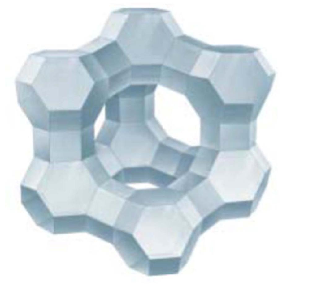
71 Zeolite structures Zeolite A Zeolite X 71
Gas Dehydration. Chapter 11 Based on presentation by Prof. Art Kidnay
 Gas Dehydration Chapter 11 Based on presentation by Prof. Art Kidnay Plant Block Schematic Adapted from Figure 7.1, Fundamentals of Natural Gas Processing, 2 nd ed. Kidnay, Parrish, & McCartney 2 Reasons
Gas Dehydration Using Glycol
 Gas Dehydration Using Glycol Manning and Thompson, Volume I Chapter 8 Outline Introduction Process Description Design Methods Design Examples Troubleshooting NATCO Glycol Dehydration Unit The NATCO glycol
Gas Dehydration Field Manual
 Gas Dehydration Field Manual Maurice Stewart Ken Arnold AMSTERDAM BOSTON HEIDELBERG LONDON NEW YORK OXFORD * PARIS SAN DIEGO SAN FRANCISCO SINGAPORE SYDNEY TOKYO QulfProfcsiion»l Publishing Is an Imprint
Gas Dehydration 6.1 INTRODUCTION. Typically, dehydration is important in three areas:
 6 Gas Dehydration Gas & Liquids from Wells Field Liquids Removal Field Acid Gas Removal Field Dehydration Field Compression CO2 Sulfur Recovery Elemental Sulfur Inlet Receiving Inlet Compression Gas Treating
Table of Contents. iii. vi Tables. Figures. viii Foreword. ix Acknowledgments
 Figures vi Tables viii Foreword ix Acknowledgments xi About the authors xiii Chapter 1. Fundamentals 1 Fluid Properties 1 Temperature 2 Pressure 3 Gravity and Miscibility 3 Solubility 4 The Ideal Gas Law
A New Look at Impurities in CO 2 for EOR and their Consequences
 A New Look at Impurities in CO 2 for EOR and their Consequences Ray McKaskle, P.E. Trimeric Corporation Presented at the 20 th Annual CO 2 Flooding Conference December 11-12, 2014 Midland, Texas Example
Influence of Process Operations on VOC and BTEX Emissions from Glycol Dehydration Units
 Page 1 of 12 Influence of Process Operations on VOC and BTEX Emissions from Glycol Dehydration Units MICHAEL W. HLAVINKA, VICENTE N. HERNANDEZ-VALENCIA, JERRY A. BULLIN, Bryan Research & Engineering, Inc.,
NATURAL GAS HYDRATES & DEHYDRATION
 Training Title NATURAL GAS HYDRATES & DEHYDRATION Training Duration 5 days Training Venue and Dates Natural Gas Hydrates & Dehydration 5 02 26 June $3,750 Abu Dhabi, UAE In any of the 5 star hotels. The
Reprinted from HydrocarbonEngineering December
 A case for dehydration Adrian Finn and Terry Tomlinson, Costain Oil, Gas & Process Ltd, UK, discuss process technology to meet water and hydrocarbon dew point specifications on natural gas storage installations.
GAS CONDITIONING FOR GAS STORAGE INSTALLATIONS
 GAS CONDITIONING FOR GAS STORAGE INSTALLATIONS Grant Johnson, Adrian Finn and Terry Tomlinson, Costain Oil, Gas & Process Ltd., UK, discuss process technology to meet water and hydrocarbon dew point specifications
Simple Dew Point Control HYSYS v8.6
 Simple Dew Point Control HYSYS v8.6 Steps to set up a simulation in HYSYS v8.6 to model a simple dew point control system consisting of: Gas chiller Flash separator Liquid stabilizer with gas recycle &
Modular Oil & Gas Equipment Onshore & Offshore
 Modular Oil & Gas Equipment Onshore & Offshore Separators & Desalters AI Energy Solutions onshore and offshore oil process solutions offer innovative technologies packaged with global project management
ISSN JEEE Vol. 7 No. 1 Eric Farda. Dehydration Simulation of Natural Gas by using Tri Ethylene Glycol in Kerendan gas field INTRODUCTION
 ISSN 2540-9352 JEEE Vol. 7 No. 1 Eric Farda Dehydration Simulation of Natural Gas by using Tri Ethylene Glycol in Kerendan gas field Abstract Eric Farda 1 1 Akademi Migas Balongan Water content in natural
LNG AGRU Designs for feed gases with low CO 2 content Dr. Torsten Katz Justin Hearn
 LNG AGRU Designs for feed es with low CO 2 content Dr. Torsten Katz Justin Hearn Common OASE unit setup for CO 2 removal also best suited for low CO 2 containing feed es? Water make-up Older LNG plants
Natural Gas Dehydration
 Natural Gas Dehydration Lessons Learned from Natural Gas STAR Producers Technology Transfer Workshop Devon Energy and EPA s Natural Gas STAR Program Fort Worth, TX June 6, 2006 Natural Gas Dehydration:
Optimization of Energy Consumption during Natural Gas Dehydration
 Abdul Qadeer 1*, Adnan Aftab 2, Imran Nazir 3 1 Department of Chemical Engineering, 2 Department of Petroleum and Gas Engineering, Balochistan University of Information Technology Engineering & Management
Simple Dew Point Control HYSYS v10. When the simulation is set up the overall PFD should look like the following figure.
 Simple Dew Point Control HYSYS v10 Steps to set up a simulation in HYSYS v10 to model a simple dew point control system consisting of: Gas chiller Flash separator Liquid stabilizer with gas recycle & compression
Novel Method for Gas Separation By: Chris Wilson and Dr. Miguel Bagajewicz
 Novel Method for Gas Separation By: Chris Wilson and Dr. Miguel Bagajewicz 2008 1 Summary Natural gas has many impurities that must be removed to increase the worth of the natural gas. There are seven
Disclaimer. Head Office # 420, 715-5th Ave SW Calgary, Alberta Canada T2P2X6 Tel: (403) Fax: (403)
 Fax: (403)") May 2008 Disclaimer This publication was prepared for the Canadian Association of Petroleum Producers, the Gas Processing Association Canada, the Alberta Department of Energy, the Alberta Energy Resources
May 2008 Disclaimer This publication was prepared for the Canadian Association of Petroleum Producers, the Gas Processing Association Canada, the Alberta Department of Energy, the Alberta Energy Resources
Sulfur Recovery. Chapter 16 Based on presentation by Prof. Art Kidnay
 Sulfur Recovery Chapter 16 Based on presentation by Prof. Art Kidnay Plant Block Schematic 2 Topics Introduction Properties of sulfur Sulfur recovery processes Claus Process Claus Tail Gas Cleanup Sulfur
Chemistry of Petrochemical Processes
 Chemistry of Petrochemical Processes ChE 464 Instructor: Dr. Ahmed Arafat, PhD Office: building 45 room 106 E-mail: akhamis@kau.edu.sa www.kau.edu.sa.akhamis files Book Chemistry of Petrochemical Processes
CRYOGENIC SOLVENT ABATEMENT (VOC s )
") CRYOGENIC SOLVENT ABATEMENT (VOC s ) 1. Introduction The technology for removing volatile organic compounds (V.O.C.s) from gas has been developed to meet the emission limits, decreased during the last
CRYOGENIC SOLVENT ABATEMENT (VOC s ) 1. Introduction The technology for removing volatile organic compounds (V.O.C.s) from gas has been developed to meet the emission limits, decreased during the last
SURFACE PRODUCTION OPERATIONS
 Training Title SURFACE PRODUCTION OPERATIONS Training Duration 5 days Training Venue and Dates Surface Production Operations 5 29 Sep 03 Oct $3,750 Abu Dhabi, UAE In any of the 5 star hotel. The exact
Addition of Static Mixers Increases Treating Capacity in Central Texas Gas Plant
 Page 1 of 5 Addition of Static Mixers Increases Treating Capacity in Central Texas Gas Plant TRACY G. CARTER, STEVEN D. BEHRENS, Mitchell Gas Services L.P., The Woodlands, Texas JOHN T. (JAY) COLLIE III,
Natural Gas Processing Unit Modules Definitions
 Natural Gas Processing Unit Modules Definitions Alberta Climate Change Office Draft Version 1.0 December 2018 1 2 3 4 5 6 7 8 9 10 11 12 14 15 16 17 18 19 20 21 22 23 24 25 26 27 28 29 30 31 32 33 34 35
Hydrate Formation in Chevron Mabee Unit for NGL Recovery and CO 2 Purification for EOR. Abstract
 Hydrate Formation in Chevron Mabee Unit for NGL Recovery and CO 2 Purification for EOR Abstract In the early 199 s, Chevron installed a new process to recover natural gas liquids (NGLs) from recycled CO
Field Operations & Inlet Receiving. Chapter 8
 Field Operations & Inlet Receiving Chapter 8 2 Topics Field Operations Wellhead operations Piping Compressor stations Pigging Inlet Receiving Separator principles Slug catcher configurations Gas Hydrates
Qualitative Phase Behavior and Vapor Liquid Equilibrium Core
 2/22/2017 Qualitative Phase Behavior and Qualitative Phase Behavior Introduction There are three different phases: solid, liquid, and gas (vapor) Energy must be added to melt a solid to form liquid If
Natural gas acid gas removal, dehydration & natural gas liquids recovery
 Natural gas acid gas removal, dehydration & natural gas liquids recovery Constantinos Hadjistassou, PhD Assistant Professor Programme in Oil & Gas (Energy) Engineering University of Nicosia Web: www.carbonlab.eu
Gas Treating Technologies: Which Ones Should Be Used and Under What Conditions? Abstract
 Gas Treating Technologies: Which Ones Should Be Used and Under What Conditions? W.G. Trey Brown Newpoint Gas Services, Inc. College Station, Texas Abstract There are numerous types of technologies available
Example SPC-2: Effect of Increasing Column P on a C3 splitter
 Example SPC-2: Effect of Increasing Column P on a C3 splitter Consider the separation of a mixture of 50 mol/hr of propane C 3 H 8 (1) and 50 mol/hr propene, C 3 H 6 (2) at a pressure of 1.1 bar and a
A Leader in Gas Conditioning Technology
 A Leader in Gas Conditioning Technology www.qbjohnson.com Who are we?: QB Johnson Manufacturing, Inc. is a leading manufacturer in the natural gas treating and processing industry. We specialize in the
10/2/2013. Gas CHEMICAL PLANTS AMMONIA METHANOL UTILITIES TOWN GASS SUPPLIES ENERGY INTENSIVE INDUSTRIES. Power Generation
 Gas Burning Feed Stock UTILITIES TOWN GASS SUPPLIES ENERGY INTENSIVE INDUSTRIES Power Generation CHEMICAL PLANTS AMMONIA METHANOL 1 Fundamentals of Natural Gas Processing Natural gas has been formed by
Item Hydrogen Gas Plant
 Item 6530. Hydrogen Gas Plant Hydro-Chem Hydrogen Generating Plant 90,000 scfh @ 200 psig. Purity 99.99% Hydrogen generating plant engineered by Hydro-Chem built in 1980. Design capacity is 90,000 scfh
Spring 2010 ENCH446 Project 1
 Spring 2010 ENCH446 Project 1 Raymond A. Adomaitis March 8, 2010 To be covered: Class syllabus (http://www.isr.umd.edu/ adomaiti/ench446), grading Team selection (4 members per team) Initial project description
Distillation DEPARTMENT OF CHEMICAL ENGINEERING
 Distillation DEPARTMENT OF CHEMICAL ENGINEERING 2 3 Weeping in distillation column 4 Distillation. Introduction Unit operation Separation process A feed mixture of two or more components is separated into
Your Presenters: Scott Bayon / Director of Sales Anguil Environmental Systems Brian Kunkle / Director of Systems Sales Verantis Environmental
 Your Presenters: Scott Bayon / Director of Sales Anguil Environmental Systems Brian Kunkle / Director of Systems Sales Verantis Environmental Solutions Group. Status and Certificate Quiz PDH Overview Today
Natural Gas Purification for Floating LNG Production. March 2013
 Natural Gas Purification for Floating LNG Production March 2013 Natural Gas Purification for FLNG Production Hollow Fiber Contactor Technology >Enables gas processing for floating LNG platforms where stringent
Field Operations & Inlet Receiving. Chapter 8
 Field Operations & Inlet Receiving Chapter 8 Topics Field Operations Wellhead operations Piping Compressor stations Pigging Inlet Receiving Separator principles Slug catcher configurations Gas Hydrates
Dr. Brian F. Towler Presented by Dr. David Bell University of Wyoming Laramie WY, USA
 Dr. Brian F. Towler Presented by Dr. David Bell University of Wyoming Laramie WY, USA Sources of CO 2 Electricity Power Plants powered by fossil fuels, especially coal fired power plants Coal Gasification
FCC Spent Catalyst Stripper Technology
 FCC Spent Catalyst Stripper Technology Paul D. Wendt FCC Technology Manager CB&I Coking and CatCracking Conference New Delhi, October 2013 Spent Catalyst Stripper Technology Big Picture Overview Process
HOW TO SELECT BEST MEG RECOVERY UNIT s CONFIGURATION?
 HOW TO SELECT BEST MEG RECOVERY UNIT s CONFIGURATION? PAPER PRESENTED AT GPA EUROPE Madrid, 17 th - 19 th September, 2014 Jérémie ESQUIER PROSERNAT Paris, France PROSERNAT Mr Jérémie ESQUIER - Business
Condensate Line Sizing for Gravity Returns from Steam Traps and Heat Recovery
 Condensate Line Sizing for Gravity Returns from Steam Traps and Heat Recovery With efficient energy use being important to all users of steam, maximizing the recovery of heat is of utmost importance. In
What is gas hydrates?
 서유택 Flow Assurance What is gas hydrates? : An ice-like solid that forms when i) Sufficient water is present ii) Hydrate former is present (i.e. C1, C2, and C3) iii) Right combination of Pressure and Temperature
Thomas G. Braga Manager, Research and Development. SulfaTreat, a Business Unit of M I L.L.C. A Smith/Schlumberger Company
 Thomas G. Braga Manager, Research and Development SulfaTreat, a Business Unit of M I L.L.C. A Smith/Schlumberger Company Who is SulfaTreat? A World Leader in H 2 S Removal for More than a Decade Today
Training Venue and Dates REF Gas Dehydration & Booster Station Utilities Nov $5,750 PE038
 Training Title GAS DEHYDRATION & BOOSTER STATION UTILITIES RESPONSIBILIT Training Duration 5 days Training Venue and Dates REF Gas Dehydration & Booster Station Utilities 5 4-8 Nov $5,750 PE038 Vienna,
HYSYS WORKBOOK By: Eng. Ahmed Deyab Fares.
 HYSYS WORKBOOK 2013 By: Eng. Ahmed Deyab Fares eng.a.deab@gmail.com adeyab@adeyab.com Mobile: 002-01227549943 - Email: adeyab@adeyab.com 1 Flash Separation We have a stream containing 15% ethane, 20% propane,
Raymond A. Adomaitis. March 7, 2012
 Raymond A. Adomaitis March 7, 2012 To be covered: Class syllabus (http://www.isr.umd.edu/ adomaiti/ench446), grading Team selection (4 members per team) Initial project description Approximate schedule
Acid Gas Treating. Chapter 10 Based on presentation by Prof. Art Kidnay
 Acid Gas Treating Chapter 10 Based on presentation by Prof. Art Kidnay Plant Block Schematic Adapted from Figure 7.1, Fundamentals of Natural Gas Processing, 2 nd ed. Kidnay, Parrish, & McCartney 2 Topics
INCREASING THE CAPACITY OF NGL RECOVERY TRAINS. Stéphane MESPOULHES XVI CONVENCIÓN INTERNACIONAL DE GAS Caracas de Mayo de 2004
 INCREASING THE CAPACITY OF NGL RECOVERY TRAINS Stéphane MESPOULHES XVI CONVENCIÓN INTERNACIONAL DE GAS Caracas WHO IS TECHNIP? 2 World Class Engineering & Construction Group in Oil & Gas Public Company
ENERGY MANAGEMENT WORKSHOP Energy Benchmarking WHAT WE HAVE LEARNED. Al Wakelin Sensor Environmental CETAC-WEST
 Energy Benchmarking Al Wakelin Sensor Environmental WHAT WE HAVE LEARNED It is a Valuable Tool However, it must be adapted to this Industry Adaptations Clusters Sour gas, Sweet Gas, Conventional Oil, Heavy
Separations and Reaction Engineering Spring Design Project. Production of Acetone
 Process Objective Function Separations and Reaction Engineering Spring 2000 Design Project Production of Acetone We would like to complete our investigation of the economic feasibility of producing 15,000
Advances in Membrane Materials Provide New Gas Processing Solutions
 Advances in Membrane Materials Provide New Gas Processing Solutions Patrick Hale Randall Gas Technologies A Division of ABB Lummus Global (ABB) Kaaeid Lokhandwala Membrane Technology and Research, Inc.
Increasing Sales Gas Output from Glycol Dehydration Plants Trina Dreher, SPE, Courtney Hocking, Michael Cavill and Adam Geard, Process Group Pty. Ltd.
 SPE-171415-MS Increasing Sales Gas Output from Glycol Dehydration Plants Trina Dreher, SPE, Courtney Hocking, Michael Cavill and Adam Geard, Process Group Pty. Ltd. Copyright 2014, Society of Petroleum
Fluid Mechanics, Heat Transfer, and Thermodynamics Fall Design Project. Production of Dimethyl Ether
 Fluid Mechanics, Heat Transfer, and Thermodynamics Fall 2001 Design Project Production of Dimethyl Ether We are investigating the feasibility of constructing a new, grass-roots, 50,000 tonne/y, (1 tonne
Methane Recovery from Pneumatic Devices, Vapor Recovery Units and Dehydrators
 Methane Recovery from Pneumatic Devices, Vapor Recovery Units and Dehydrators Ministerio de Minas y Energia Ministerio de Ambiente, Vivienda y Desarrollo Territorial Occidental Oil & Gas Corporation and
Available online at Energy Procedia 100 (2009) (2008) GHGT-9. Allan Hart and Nimalan Gnanendran*
 (2008) GHGT-9. Allan Hart and Nimalan Gnanendran*") Available online at www.sciencedirect.com Energy Procedia 100 (2009) (2008) 697 706 000 000 Energy Procedia www.elsevier.com/locate/procedia www.elsevier.com/locate/xxx GHGT-9 Cryogenic CO 2 Capture in
Available online at www.sciencedirect.com Energy Procedia 100 (2009) (2008) 697 706 000 000 Energy Procedia www.elsevier.com/locate/procedia www.elsevier.com/locate/xxx GHGT-9 Cryogenic CO 2 Capture in
O 2 n-site Oxygen Production
 O 2 n-site Oxygen Production DeJuan Frank Stew Harwood University of Oklahoma May 4, 2006 1 Outline Project Goal Brief Theory Progression of Project Design Design Conclusions Business and Economic Analysis
Training Fees 4,000 US$ per participant for Public Training includes Materials/Handouts, tea/coffee breaks, refreshments & Buffet Lunch.
 Training Title GAS CONDITIONING & PROCESSING Training Duration 5 days Training Venue and Dates Gas Conditioning & Processing 5 06-10 January 2019 $4,000 Dubai, UAE Trainings will be conducted in any of
Production of Pipeline Quality Natural Gas With the Molecular Gate CO 2 Removal Process
 Production of Pipeline Quality Natural Gas With the Molecular Gate CO 2 Removal Process James Wills, P.E., SPE, Tidelands Oil Production Company; Mark Shemaria, SPE, Tidelands Oil Production Company; Michael
GAS CONDITIONING & PROCESSING TRAINING
 Training Title GAS CONDITIONING & PROCESSING TRAINING Training Duration 5 days Training Venue and Dates Gas Conditioning & Processing 5 07 11 April $3,750 Dubai, UAE In any of the 5 star hotels. The exact
by: Steven M. Puricelli and Ernesto Vera-Castaneda MECS, Inc USA
 MECS SOLVR REGENERATIVE SULFUR DIOXIDE TECHNOLOGY by: Steven M. Puricelli and Ernesto Vera-Castaneda MECS, Inc USA Prepared for AMERICAN INSTITUTE OF CHEMICAL ENGINEERS 4798 S. Florida Ave. #253 Lakeland,
Taravosh Jam Design & Engineering Co.
 Taravosh Jam Design & Engineering Co. Taravosh Jam co. as an Iranian EPC contractor supplies following refinery equipment and facilities based on the know-how and to international standards. 1- The Main
MOLECULAR GATE TECHNOLOGY FOR (SMALLER SCALE) LNG PRETREATMENT
 LNG PRETREATMENT") MOLECULAR GATE TECHNOLOGY FOR (SMALLER SCALE) LNG PRETREATMENT Presented at the 2010 Gas Processors 89 th Annual Convention Austin, TX March, 2010 Michael Mitariten, P.E. Guild Associates, Inc. Dublin,
MOLECULAR GATE TECHNOLOGY FOR (SMALLER SCALE) LNG PRETREATMENT Presented at the 2010 Gas Processors 89 th Annual Convention Austin, TX March, 2010 Michael Mitariten, P.E. Guild Associates, Inc. Dublin,
Amine Plant Energy Requirements & Items impacting the SRU
 Amine Plant Energy Requirements & Items impacting the SRU 10 October 2016 AGRU energy needs Amine energy requirements Regeneration Processing effects Leanness required Determine required leanness Over
Thiopaq Technical Presentation
 Thiopaq Technical Presentation Stranded Gas Defined! Gas that is not marketable for one or more reasons!! Small volume!! Low pressure!! Btu value too low or too high!! Inerts such as nitrogen and carbon
WE CREATE IMPOSSIBLE ABOUT US. KASRAVAND is a DESIGN and MANUFACTURING Company
 PROCESS SOLUTIONS ABOUT US KASRAVAND is a DESIGN and MANUFACTURING Company with high Engineering and Management competency. We design & manufacture PROCESS PACKAGES such as FLARE GAS RECOVERY,TEG,MEG,WATER
FLEXERAMIC CERAMIC STRUCTURED PACKING SYSTEMS
 CERAMIC STRUCTURED PACKING SYSTEMS Packing Systems For Heat and Mass Transfer Applications - Distillation, Absorption, Stripping, Heat Exchange, Gas Mixing, Extraction The high performance structured packing
Filtration for Oil and Gas
 Filtration for Oil and Gas Treated Gas Outlet Amine Cooler Re-Generator Acid Gas Amine Pump Charcoal Filter Contactor Lean Amine Fine Filter Cartridges Lean Amine Pre-Filter Cartridges Reflux Accumulator
GATE Solution 2000 to 2015 GATE SOLUTION to Detailed solution of each question CHEMICAL ENGINEERING GATE SOLUTION
 SAMPLE STUDY MATERIAL GATE SOLUTION 000 to 015 Detailed solution of each question CHEMICAL ENGINEERING GATE SOLUTION Subject-wise reducing year CONTENTS GATE Solution 1. Process Calculations 1-19. Thermodynamics
HYDROGEN R&D AT INEEL
 HYDROGEN R&D AT INEEL Overview Joseph C. Perkowski, Ph.D. 208-526-5232 April 27, 2004 1 Long-Term Vision: The Hydrogen Model Community A Hydrogen City or Hydrogen Corridor INEEL, SE Idaho or other venue
Fluid Mechanics, Heat Transfer, and Thermodynamics. Design Project. Production of Acetone
 Fluid Mechanics, Heat Transfer, and Thermodynamics Design Project Production of Acetone We are investigating the feasibility of constructing a new, grass-roots, 15,000 metric tons/year, acetone plant.
STRIPBURN SIMPLE AND EFFICIENT BTEX CONTROL FOR DIRECT FIRED TEG REBOILERS
 STRIPBURN SIMPLE AND EFFICIENT BTEX CONTROL FOR DIRECT FIRED TEG REBOILERS Ralph Hicks and Dale Gallaher PetroDesigns, Inc. Harvey, Louisiana Allen Logue Gly-Tech, Inc. Harvey, Louisiana ABSTRACT The STRIPBURN
PROCESS MOISTURE ANALYZERS Measuring moisture in gas or HC liquids in hazardous areas
 PROCESS MOISTURE ANALYZERS Measuring moisture in gas or HC liquids in hazardous areas EExd Construction Safety by containment PROCESS MOISTURE ANALYZER Channel 1 dew-point & pressure sensor Through-glass
MANAGEMENT & DISPOSAL OF CO 2 IN VENEZUELA
 International Gas Union Research Conference 19-21 October 2011 MANAGEMENT & DISPOSAL OF CO 2 IN VENEZUELA Maria Emilia Escar VENEZUELA ABSTRACT The Bolivarian Republic of Venezuela is considered as one
Field Testing and Independent Review of Post-Combustion CO 2 Capture Technology
 Field Testing and Independent Review of Post-Combustion CO 2 Capture Technology Presented by Phil Boyle, President and COO, Powerspan Corp. McIlvaine Company, Carbon Management Strategies & Technologies
Rapid estimation of equilibrium water dew point of natural gas in TEG
 From the SelectedWorks of ali ali 2009 Rapid estimation of equilibrium water dew point of natural gas in TEG ali ali Available at: https://works.bepress.com/bahadori/3/ Journal of Natural Gas Science and
Production of Ethylene from Natural Gas
 Production of Ethylene from Natural Gas Team #5 The Lindgren Group, LLC, a subsidiary of MichiChem Corp. April 22, 213 Production of Ethylene from Natural Gas Using Thermal Cracking and Cryogenic Distillation
SYNTHETIC NATURAL GAS PLANT. Philadelphia, PA
 SYNTHETIC NATURAL GAS PLANT Philadelphia, PA SYNTHETIC NATURAL GAS PLANT The SNG facility was constructed in 1977 but has seen very little operational activity. The SNG Facility employs the British Gas
Ethylene Production Plant Design
 Cooper Union for the Advancement of Science and Art Che 161.2: Process Evaluation and Design II Ethylene Production Plant Design Authors: Ghazal Erfani Ciera Lowe Joshua Mayourian Instructor: Professor
Offshore platform FEED Yutaek Seo
 Yutaek Seo Offshore platform FEED Processing in offshore platforms CPF Process General Reservoir Wellbore HC Products Crude Oil Stabilized Oil Oil Fluid (Black / Volatile Oil) Associated Produced Water
PRESSURE SWING ADSORPTION NITROGEN GENERATION SYSTEM. GDN2 Series
 PRESSURE SWING ADSORPTION NITROGEN GENERATION SYSTEM GDN2 Series GARDNER DENVER NITROGEN GENERATORS Where is Nitrogen Used? In many applications, oxygen is the enemy. Oxygen can cause food to spoil, rubber
26.36 Mass Transfer (Optimum Reflux Ratio)
") 26.36 Mass Transfer (Optimum Reflux Ratio) A sieve-plate distillation column is being designed to handle 700 lb mol of feed per hour. The unit is to operate continuously at a total pressure of 1 atm. The
26.36 Mass Transfer (Optimum Reflux Ratio) A sieve-plate distillation column is being designed to handle 700 lb mol of feed per hour. The unit is to operate continuously at a total pressure of 1 atm. The
Innovative Stripper Configurations to Reduce the Energy Cost of CO 2 Capture
 Abstract Innovative Stripper Configurations to Reduce the Energy Cost of CO 2 Capture by Gary T. Rochelle (gtr@che.utexas.edu) Department of Chemical Engineering The University of Texas at Austin Austin,
UNIQUE DESIGN CHALLENGES IN THE AUX SABLE NGL RECOVERY PLANT
 UNIQUE DESIGN CHALLENGES IN THE AUX SABLE NGL RECOVERY PLANT Presented at the 81 st Annual Convention of the Gas Processors Association March 11, 2002 Dallas, Texas Joe T. Lynch, P.E. Ortloff Engineers,
Air and Gas Drying with Activated Alumina
 Air and Gas Drying with Activated umina Air and Gas Drying with Activated umina Water is removed from air and other gases to avoid undesirable effects caused by liquid and ice formation, corrosion, and
Contents PROCESSING NATURAL GAS. Introduction
 Gas Sweetening Part Gas Sweetening,2 Contents PROCESSING NATURAL GAS - ACID GAS CONSIDERATIONS -4 SWEETENING PROCESSES -7 SOLID BED PROCESSES -8 CHEMICAL SOLVENT PROCESSES -27 PHYSICAL SOLVENT PROCESSES
Title slide. LNG Technology. Compiled by PD.Supriyadi
 Title slide LNG Technology Compiled by PD.Supriyadi 1 What is LNG? Colorless, odorless, non toxic hydrocarbon in very low temperature liquid form (cryogenic) Mainly (90% plus) is Methane, the lightest
UCARSOL AP 804 and AP 806 Solvents
 Technical Information UCARSOL AP 804 and AP 806 Solvents For Bulk CO 2 Removal Introduction UCARSOL AP 804 and UCARSOL AP 806 Solvents are two additions to a series of advancedperformance gas treating
Reducing Methane Emissions Provides Operating Benefits for International Oil and Gas Companies: A Case Study
 Reducing Methane Emissions Provides Operating Benefits for International Oil and Gas Companies: A Case Study Oil and Gas Methane Emissions Reduction Workshop Tomsk, Russia 14-16 September 2005 Agenda How
Reactors and Separations Design Project. Phthalic Anhydride Production
 Reactors and Separations Design Project Phthalic Anhydride Production We are continuing our evaluation of process alternatives for the production of Phthalic Anhydride via the catalytic oxidation of o-xylene.
562,538. Ranjani V. Siriwardane REMOVAL OF HYDROGEN SULFIDE FROM COAL GAS DURABLE REGENERABLE SORBENT PELLETS FOR METC. 5 z 71 -I. zcn.
 62,38 DURABLE REGENERABLE SORBENT PELLETS FOR Ranjani V. Siriwardane REMOVAL OF HYDROGEN SULFIDE FROM COAL GAS!2 3 2 m C 0 z 0 71 -I N 0 UI 0 zcn UI 0 0 0 C srn C Z If z% rn 0 METC -.-- I PATENT DOE S-71,74
A DESIGN REVIEW OF STEAM STRIPPING COLUMNS FOR WASTEWATER SERVICE. Timothy M. Zygula. Huntsman Polymers 2504 South Grandview Ave Odessa, TX 79760
 A DESIGN REVIEW OF STEAM STRIPPING COLUMNS FOR WASTEWATER SERVICE Paper 7A Timothy M. Zygula Huntsman Polymers 2504 South Grandview Ave Odessa, TX 79760 Prepared for Presentation at the The AIChE 2007
Processes to Recover and Purify
 Processes to Recover and Purify Carbon Dioxide Jennifer L. Anthony Department of Chemical Engineering Kansas State t University it CHE 670 Sustainability Seminar: Greenhouse Gases; Carbon Taxes and Trading;
Membrane Technologies for Tritium Recovering in the Fusion Fuel Cycle
 Membrane Technologies for Tritium Recovering in the Fusion Fuel Cycle S. Tosti 1), L. Bettinali 1), C. Rizzello 2), V. Violante 1) 1) Euratom-ENEA Fusion Association, C. R. ENEA Frascati, 00044 Frascati
1) ABSORPTION The removal of one or more selected components from a gas mixture by absorption is probably the most important operation in the control
 ABSORPTION The removal of one or more selected components from a gas mixture by absorption is probably the most important operation in the control") 1) ABSORPTION The removal of one or more selected components from a gas mixture by absorption is probably the most important operation in the control of gaseous pollutant emissions. Absorption is a process
1) ABSORPTION The removal of one or more selected components from a gas mixture by absorption is probably the most important operation in the control of gaseous pollutant emissions. Absorption is a process
Fluid Mechanics, Heat Transfer, Fluid Mechanics Design Project. Production of Ethanol
 Fluid Mechanics, Heat Transfer, Fluid Mechanics Design Project Production of Ethanol Your assignment is to continue evaluating the details of a process to produce 30,000 tonne/y of ethanol from ethylene.
Problems at the Cumene Production Facility, Unit 800
 Problems at the Cumene Production Facility, Unit 800 Background Cumene (isopropyl benzene) is produced by reacting propylene with benzene. During World War II, cumene was used as an octane enhancer for
moleliquid := mole molegasinliq := mole totalmoleliquid := molegasinliq + moleliquid molegasinliq molegasinliq + moleliquid totalmoleliquid
 Control of Gaseous Air Pollutant Emissions by Absorption into Liquid Pilat In general, the control of gaseous air pollutant emissions (at low pollutant concentrations such as less than 0.5% or 0.5/00 or
PROCESSING NATURAL GAS Leontev A.A. Vladimirskiy State University named after the Stoletov brothers Vladimir, Russia
 PROCESSING NATURAL GAS Leontev A.A. Vladimirskiy State University named after the Stoletov brothers Vladimir, Russia ПЕРЕРАБОТКА ПРИРОДНОГО ГАЗА Леонтьев А.А. Владимирский государственный университет имени