Geneva Dam. Design of a Steep, Temporary, Riprap Ramp
|
|
|
- Malcolm Johnson
- 6 years ago
- Views:
Transcription


1 Geneva Dam Design of a Steep, Temporary, Riprap Ramp
2 A Run-of of-river Dam Analysis for Geneva Dam Credit to: Yu-Chun Su, Ph.D., P.E., CFM David T. Williams. Ph.D., P.E, CFM
3 Presentation Purpose History of the Geneva Dam Problems with the dam Potential Solutions Modeling Hydraulic Characteristics of the Dam Rock ramp sizing

4 Fox River Dams

5 History of Geneva Dam Built in 1837 for Sterling Sawmill

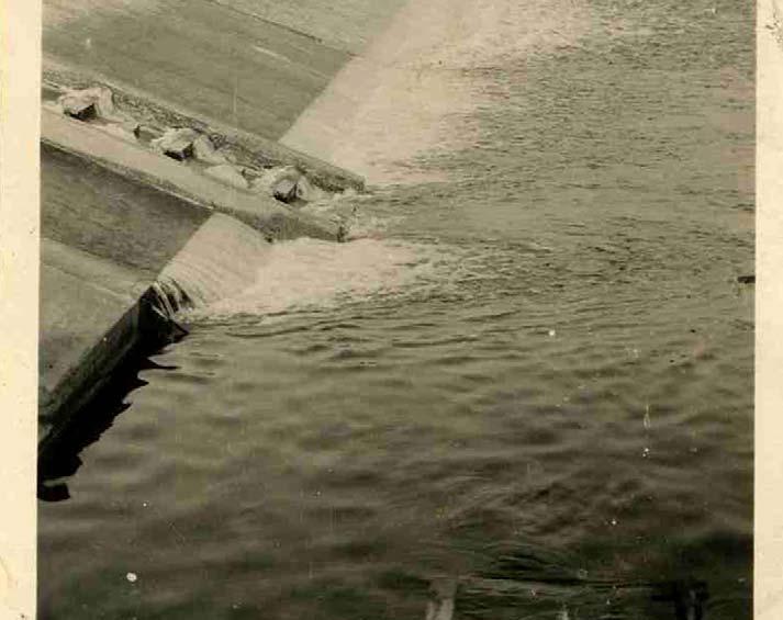
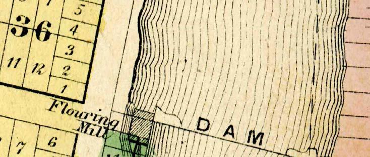
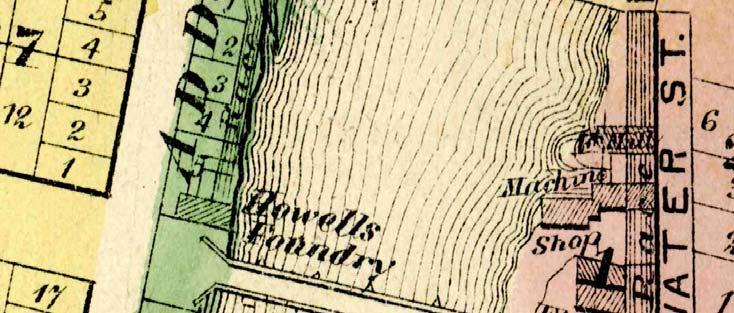
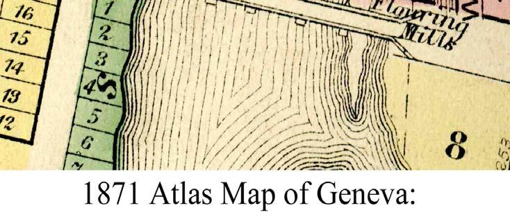
6 Several mills operational along 2 raceways by the 1870 s

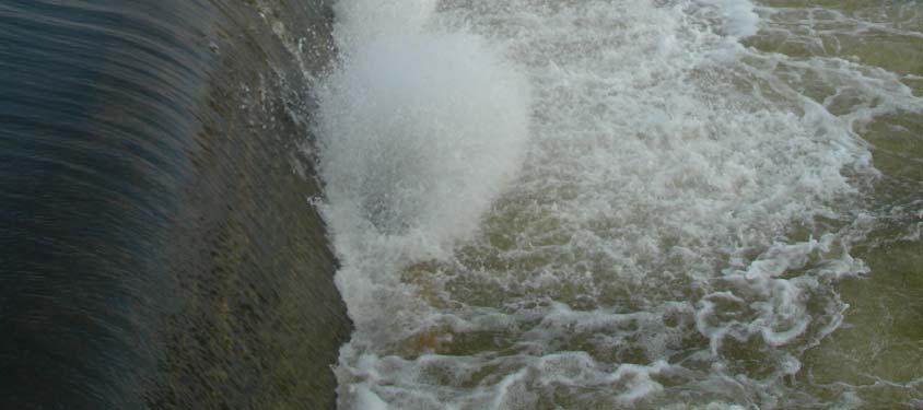
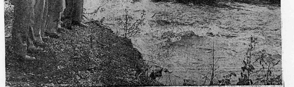
7 Popular Swimming Hole


8 And Popular Fishing Hole


9 1950 s: Problems with the dam

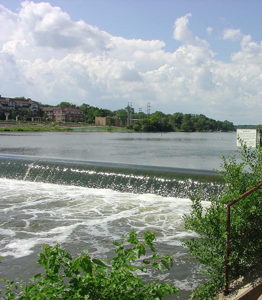
10 1960 New Ogee Spillway Dam
11


12 Geneva Dam Basic information Type - ogee Material - concrete Weir Length ft Height - 13 ft Spillway crest elevation ft Length of pool miles Area of Pool - 89 acres


13 Geneva Dam Problems Public Safety Fish Passage Boat Passage


14 Public Safety Hydraulic Roller causes safety concerns Several dams on the Fox River have had recorded deaths


15 IDNR Requirements for Dams Which we own or are likely to own and For which State funds are to be expended Public Safety Ecological improvements to the river Development of recreational opportunities


16 Potential Dam Alternatives * Dam Removal * Dam Modification (Spillway Steps & Fish Ladder) * Rock Ramp (Temporary or permanent)

17 Criteria for Design of Replacement Structure Fish Passage Flood Conveyance Long Term City Planning Cost Effectiveness River Trails Boat Passage Safety Healthy Ecosystem Sediment Transport Predictable Results
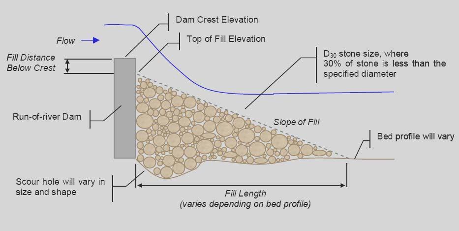
18 Objectives of Geneva Dam Study Identify suitable methodologies to define hydraulic characteristics and alternatives to minimize roller problem Development of methodologies to support the sizing of a temporary rock ramp downstream of Geneva Dam: To minimize existing roller for up to or over a 5-year frequency flow event Rock ramp stable up to 100-year frequency flow 20-year expected project life
19 MISSION: Find a computer model that: 1. Will simulate the hydraulics of a submerged hydraulic jump roller ; 2. Will run easily on existing IDNR desk top computers; 3. Will require minimal training to use; and 4. Is inexpensive.
20 Use of 1-D (HEC-RAS) Model Conditions suitable for 1-D (HEC-RAS) modeling: A design unit discharge along dam crest can be assumed. Approaching flows are generally perpendicular to the weir. Design water velocities have insignificant lateral component along riprap slope. Conditions requiring 2D/3D modeling: Alternatives involving significant lateral or vertical variations in flow field, such as notches or unusual upstream flow alignment. Physical conditions (bathymetry/geometry) resulting in 2D/3D flow field.
21 Rock Ramp Sizing Evaluation
22
23 Geneva Dam Rock Ramp Sizing Approach Select design flow: Minimize roller at 5-year frequency Stable ramp at 10-, 25-, and 100-year frequencies Obtain design velocities and water depth: HEC-RAS modeling. Using 5% and 10% rock ramp slopes. Using two Manning s n: and Mixed flow turned on. Compare riprap sizes via four methodologies: Rock ramp sizing spreadsheets. Recommend final sizes and gradation.
24 Riprap Sizing Methods Examined Four Methods Evaluated: U.S. Army Corps of Engineers' (COE) method for steep slopes (from EM ). Isbash Method, high turbulence (from EM ). Frizell, Ruff and Mishra method for overtopping flows. Hydraulic Engineering Circular 15, Design of Roadside, Channels with Flexible Linings (HEC-15, FHWA).
25 U.S Army Corps of Engineers Method for Steep Slopes (EM ) Where: S = Slope of bed, q = unit discharge Thickness = 1.5 x D 100 Slope can range from 2 to 20% Assumes no tailwater but horizontal extension of the ramp will minimize this limitation
26 Isbash Method D 50 = 2gC V 2 2 a ( G 1) s D 50 = stone size, ft V a = average Channel Velocity, ft/s G s = specific gravity of stone (γ s / γ w ) g = acceleration of gravity, ft/s 2 C = 0.86 for high turbulence zones = 1.20 for low turbulence zones
27 Frizell, Ruff, and Mishra V i = interstitial velocity (m/s) D 50 = initially determined from design curves g S = gravitational constant (9.81 m/s2) = embankment slope C u = coefficient of uniformity = D 60 /D 10
28 FHWA HEC-15 for Steep Slopes d a g Fr = average flow depth in the channel = acceleration due to gravity = Froude number REG = roughness element geometry CG α = channel geometry = unit conversion constant, 1.0 (SI) and 1.49 (CU)
29 FHWA HEC-15 for Steep Slopes T = channel top width (ft)
30 Riprap Ramp Results Return Period 5-yr Channel Slope Manning's n Methodology COE-EM COE-EM1601-Isbach FrizellRuffMishra FHWA D 30 (ft) D 50 (ft) D 50 (ft) D 50 (ft) Average 10-yr yr yr % 5-yr D 50 (ft) yr yr yr yr yr yr yr % 5-yr yr yr yr
31 Gradation Determination Based Upon COE Gradations
32 General Comments on Riprap Methods All these methods assume that the riprap is at least moderately angular and for temporary conditions only. The riprap methods and the ramp do not take into consideration ice or debris impacts. Because of the high turbulence, vibration of the riprap would tear filter fabric recommend granular filter. Note that the COE method for steep slopes gives D 30 for the representative riprap size whereas the others give D 50. To make the methods comparable, the D 30 result was converted to an equivalent D50 using the formula D 30 = D 50 (D 15 / D 85 ) 0.33, which is related to the COE gradation method
33 Basis of Method Selection Isbash method was developed for the construction of dams by depositing rock into running water. If the dumped rock did not slide or roll under those conditions, the rock size was considered stable - too conservative. HEC-15 method uses an arbitrary safety factor of 1.5 overly conservative. For the Frizell et al. method, the unit discharge for the Geneva Dam exceeded those presented in the graph used in determining the D 50 of the riprap and values had to be extrapolated. The COE method shows reasonable results for the full range of ramp slopes and discharges and was therefore recommended for design of the riprap for Geneva Dam.
34 5% or 10% Slope? 5% or 10% slopes will minimize the formation of the dangerous hydraulic rollers for the 5-year flow events and will function properly per design requirements. Therefore, recommendations for either a slope of 5% or 10% depend on the costs. The 10% ramp slope has a larger gradation (D 30 of 1.70 feet) than the 5% ramp slope (D 30 of 1.10 feet ) but would have a smaller overall riprap volume. Since the costs for riprap is a combination of availability of large sized rock as the volume of riprap, the recommended ramp slope should be based upon local rock supply conditions.

35 COSTS CORPS METHOD 10% SLOPE Less rock but bigger rock 19,800 TONS $89/TON $2,485,000 CORPS METHOD 5% SLOPE More rock but smaller rock 35,700 TONS $85/TON $3,800,000
36 Where are we headed now?

37 Investigate Temporary Rock Ramp Placement


38 INVESTIGATE PERMANENT ROCK RAMP DESIGN ARCH RAPIDS LONGITUDINAL PROFILE (consider Luther Aadland Design) Public Safety Fish Passage Recreational Boat Passage Minimum tailwater stage 20:1 SLOPE DAM

39 Investigate Dam Removal

40 Compare to Stair Step Dam Modification at Yorkville $2,900,000

41
42 Frizell, Ruff, and Mishra V ave = V i x n p n p = porosity of the riprap
Index. outlet protection Rev. 12/93
 6 Index outlet protection level spreader outlet stabilization structure 6.40.1 6.41.1 Rev. 12/93 Practice Standards and Specifications 6.40 level spreader Definition Purpose Conditions Where Practice Applies
Strategies to Mitigate Scour Critical Structures
 U.S. Department of Transportation Federal Highway Administration Strategies to Mitigate Scour Critical Structures Dan Ghere Hydraulics Engineer (708) 283-3557 dan.ghere@dot.gov Support Material HEC 23,
Drop Height For Channel Erosion Control
 Drop Height For Channel Erosion Control James C.Y. Guo, Professor and Director Department of Civil Engineering, U. of Colorado at Denver, Denver, Colorado 8017 E-mail: James.Guo@cudenver.edu Introduction
Prepared for Urban Drainage and Flood Control District
 BERM FAILURE TECHNICAL ANALYSES SOUTH PLATTE GRAVEL PIT EVALUATION CRITERIA Prepared for Urban Drainage and Flood Control District Wright Water Engineers, Inc. January 2013 121-030.000 TABLE OF CONTENTS
Prototype modifications within a flood control channel to improve fish passage in Mill Creek near Walla Walla, WA
 University of Massachusetts - Amherst ScholarWorks@UMass Amherst International Conference on Engineering and Ecohydrology for Fish Passage International Conference on Engineering and Ecohydrology for Fish
Appendix J Hydrology and Hydraulics
 Appendix J Hydrology and Hydraulics Marsh Lake Dam Ecosystems Restoration Feasibility Study Hydraulics & Hydrology Appendix January 2011 Contents List of Figures iii List of Tables iii I. General 1 II.
Water Control Structures Selected Design Guidelines Alberta Environment Page 13-1
 Alberta Environment Page 13-1 13.0 DROP INLET SPILLWAYS 13.1 General The drop inlet spillway is commonly used for providing flood protection for earth dams which have smaller reservoirs and/or smaller
Rubble-Mound Stability
 Design of Marine Structures Rubble-Mound Stability Steven A. Hughes. Ph.D., P.E. Coastal and Hydraulics Laboratory US Army Engineer Research and Development Center David R. Basco. Ph.D., P.E. Coastal Engineering
Standards for Soil Erosion and Sediment Control in New Jersey May 2012 STANDARD FOR RIPRAP. Conditions Where Practice Applies
 STANDARD FOR RIPRAP Definition A layer of loose rock, aggregate, bagged concrete, gabions, or concrete revetment blocks placed over an erodible soil surface. Purpose The purpose of riprap is to protect
of the Crump weir Modelling of composite type variation
 Modelling of composite type variation of the Crump weir Ashley Maritz BEng Honours Student Department of Civil Engineering University of Pretoria aamaritz9@gmail.com Dr Pieter Wessels Specialist Engineer
APPENDIX G DIVERSION AND PELICAN LAKE CUTOFF CHANNELS HYRAULICS AND BRIDGE TECHNICAL MEMORANDUM
 APPENDIX G DIVERSION AND PELICAN LAKE CUTOFF CHANNELS HYRAULICS AND BRIDGE TECHNICAL MEMORANDUM To: File Memo From: Matt Redington, P.E. Project: Watertown South Connector CC: Date: March 6, 2007; revised
Hydraulic Modeling with HY-8
 Hydraulic Modeling with HY-8 Linda Hansen PE, PWS MI Dept. of Environmental Quality Water Resources Division UP District Floodplain Engineer Today s Outline What is HY-8? Best Applications & Limitations
LOCATION AND DESIGN DIVISION
 VIRGINIA DEPARTMENT OF TRANSPORTATION LOCATION AND DESIGN DIVISION INSTRUCTIONAL AND INFORMATIONAL MEMORANDUM GENERAL SUBJECT: CULVERT DESIGN SPECIFIC SUBJECT: COUNTERSINKING AND LOW FLOW CONSIDERATIONS
Scour Analysis and Countermeasure Design
 Scour Analysis and Countermeasure Design for UNION STREET RAILROAD BRIDGE (Trail Connection Project) Key No. 11085 ODOT, Region 2 Local Agency On-Call ATA 23456 WOC 1 City of Salem, Urban Development HDR
VII - WATER CONTROL PLAN
 VII - WATER CONTROL PLAN 7-01. General Objectives. Regulation of Saylorville Lake in conjunction with Lake Red Rock provides flood control benefits along both the Des Moines and Mississippi Rivers. Additionally,
3/21/2012. Dave Conkel State Aid Bridge Engineer. Brian Homan State Aid Bridge Plans Engineer
 3/21/2012 Dave Conkel State Aid Bridge Engineer Brian Homan State Aid Bridge Plans Engineer 1 3/21/2012 Check Q100, V100 and drainage area versus up and down stream bridges. Check proposed channel bottom
CLAY STREET BRIDGE REPLACEMENT
 HYDROLOGY /HYDRAULICS REPORT. EL DORADO COUNTY CLAY STREET BRIDGE REPLACEMENT Prepared by: Joseph Domenichelli Domenichelli & Associates 1107 Investment Blvd., Suite 145 El Dorado Hills, California 95762
Conceptual Design and Feasibility of a Natural Fishway at the Fremont BART Weir, Alameda Creek, California
 Conceptual Design and Feasibility of a Natural Fishway at the Fremont BART Weir, Alameda Creek, California Final Report September 2005 Prepared by Center for Ecosystem Management and Restoration, Oakland,
Chapter 11 Culverts and Bridges
 Chapter 11 Culverts and Bridges Contents 1.0 Introduction... 1 2.0 General Design... 1 2.1 Design Criteria... 1 2.2 Design Flows... 1 2.3 Permitting and Regulations... 1 2.4 Aesthetics and Safety... 2
Highway Drainage 1- Storm Frequency and Runoff 1.1- Runoff Determination
 Highway Drainage Proper drainage is a very important consideration in design of a highway. Inadequate drainage facilities can lead to premature deterioration of the highway and the development of adverse
RETENTION BASIN EXAMPLE
 -7 Given: Total Tributary Area = 7.5 ac o Tributary Area within Existing R/W = 5.8 ac o Tributary Area, Impervious, Outside of R/W = 0.0 ac o Tributary Area, Pervious, Outside of R/W = 1.7 ac o Tributary
7.0 ENERGY DISSIPATION DESIGN
 SPALDING COUNTY, GEORGIA CHAPTER 7 7.0 ENERGY DISSIPATION DESIGN... 7-1 7.1 SYMBOLS AND DEFINITIONS... 7-1 7.2 DESIGN CRITERIA... 7-1 7.2.1 INTRODUCTION... 7-1 7.2.2 GENERAL CRITERIA... 7-2 7.2.3 EROSION
MILL CREEK FISH PASSAGE CONCEPTUAL DESIGNS FINAL REPORT
 MILL CREEK FISH PASSAGE CONCEPTUAL DESIGNS FINAL REPORT Prepared for Tri State Steelheaders Contact: Brian Burns 216 N. Roosevelt, PO Box 1375 Walla Walla, WA 99362 Prepared by Waterfall Engineering, L.L.C.
Failure Consequence Classification
 Failure Consequence Classification Audience: Dam Safety Officers (DSO) Owners of small dams Community emergency preparedness coordinators Introduction This document provides an overview of failure consequence
Basic Design of Replogle Flumes
 ITRC Report No. R 02-010 IRRIGATION TRAINING AND RESEARCH CENTER California Polytechnic State University San Luis Obispo, California 93407 www.itrc.org Basic Design of Replogle Flumes Replogle flumes are
CHAPTER 8 SEEPAGE CONTROL IN EMBANKMENTS
 CHAPTER 8 SEEPAGE CONTROL IN EMBANKMENTS 8-1. General. All earth and rock-fill dams are subject to seepage through the embankment, foundation, and abutments. Seepage control is necessary to prevent excessive
Chapter 11 Culverts and Bridges
 Chapter 11 Table of Contents 11-1 Introduction... 1 11-2 General Design... 1 11-2-1 Design Criteria... 1 11-2-2 Design Flows... 1 11-2-3 Permitting and Regulations... 2 11-2-4 Aesthetics and Safety...
Chapter 11 Culverts and Bridges
 Chapter 11 Table of Contents 11-1 Introduction... 1 11-2 General Design... 1 11-2-1 Design Criteria... 1 11-2-2 Design Flows... 1 11-2-3 Permitting and Regulations... 2 11-2-4 Aesthetics and Safety...
Development of a Stage-Discharge Rating for Site Van Bibber Creek at Route 93
 Development of a Stage-Discharge Rating for Site 330 - Van Bibber Creek at Route 93 Prepared for: Urban Drainage and Flood Control District 2480 W. 26 th Avenue Suite 156-B Denver, CO 80211 May 19, 2006
Coastal and Hydraulics Laboratory
 ERDC/CHL TR-10-1 Numerical Model of the Hoosic River Flood- Control Channel, Adams, MA Richard L Stockstill, Jane M. Vaughan, and Keith Martin February 2010 Coastal and Hydraulics Laboratory Approved for
Outlet Flow Velocity in Circular Culvert
 Archives of Hydro-Engineering and Environmental Mechanics Vol. 61 (2014), No. 3 4, pp. 193 203 DOI: 10.1515/heem-2015-0013 IBW PAN, ISSN 1231 3726 Outlet Flow Velocity in Circular Culvert Wojciech Szpakowski
Low Gradient Velocity Control Short Term Steep Gradient Channel Lining Medium-Long Term Outlet Control Soil Treatment Permanent [1]
![Low Gradient Velocity Control Short Term Steep Gradient Channel Lining Medium-Long Term Outlet Control Soil Treatment Permanent [1]](/thumbs/82/86216855.jpg "Low Gradient Velocity Control Short Term Steep Gradient Channel Lining Medium-Long Term Outlet Control Soil Treatment Permanent [1]") Energy Dissipaters DRAINAGE CONTROL TECHNIQUE Low Gradient Velocity Control Short Term Steep Gradient Channel Lining Medium-Long Term Outlet Control Soil Treatment Permanent [1] [1] The design of permanent
Energy Dissipaters DRAINAGE CONTROL TECHNIQUE Low Gradient Velocity Control Short Term Steep Gradient Channel Lining Medium-Long Term Outlet Control Soil Treatment Permanent [1] [1] The design of permanent
A Study on Physical Model Test for Cheongpyeong Dam Discharge Recalculation
 Engineering, 014, 6, 731-74 Published Online October 014 in SciRes. http://www.scirp.org/journal/eng http://dx.doi.org/10.436/eng.014.611071 A Study on Physical Model Test for Cheongpyeong Dam Discharge
Chapter 10. Conduit Outlet Structures Introduction General Layout Information
 10.0 Introduction This section addresses the design of culvert outlets, which are typically oriented in-line with the flow in a drainageway, and storm sewer outlets, which are typically oriented perpendicular
Pier (TYP) Tainter Gate (TYP) Chapter 2 Applications General
 Tainter Gate (TYP) Chapter 2 Applications General") Chapter 2 Applications 2-1. General a. Application. Controlled spillways include crest gates that serve as a movable damming surface allowing the spillway crest to be located below the normal operating
Chapter 2 Applications 2-1. General a. Application. Controlled spillways include crest gates that serve as a movable damming surface allowing the spillway crest to be located below the normal operating
HYDRAULICS OF CULVERTS
 HYDRAULICS OF CULVERTS Walter F. Silva, Ph.D., P.E. December 8 & 11, 2015 Now you know.. UNIFORM, CRITICAL FLOW and PIPE FLOW Classification of Culvert Flow USGS classifies culvert flow into six types,
Asst.Prof.Dr. Jaafar S. Maatooq. 1 st Semester HYDRAULIC STRUCTUER, KINDS & FUNCTIONS 1 of 26
 1 st Semester HYDRAULIC STRUCTUER, KINDS & FUNCTIONS 1 of 26 1 st Semester HYDRAULIC STRUCTUER, KINDS & FUNCTIONS 2 of 26 Water is often more useful to people when it is properly controlled, conveyed,
Hydraulic Report. County Road 595 Bridge over Mulligan Creek. Prepared By AECOM Brian A. Hintsala, P.E
 Prepared for: Prepared by: Marquette County Road Commission AECOM Ishpeming, MI Marquette, MI 60240279 December 9. 2011 Hydraulic Report County Road 595 Bridge over Mulligan Creek Prepared By AECOM Brian
Bridge Planning Updates. Bridge Planning Practitioners Workshop April 2012
 Bridge Planning Updates Bridge Planning Practitioners Workshop April 2012 Bridge Website Bridge Website Bridge Website Bridge Website BPG 11 Stormwater Management at Rural Bridges Released July 2010 Documents
PART 3 - STANDARDS FOR SEWERAGE FACILITIES DESIGN OF STORM SEWERS
 PART 3 - STANDARDS FOR SEWERAGE FACILITIES 3.3 - DESIGN OF STORM SEWERS 3.301 Design of Storm Sewers A. General Information B. Investigations and Surveys C. Special Projects 3.302 Design Criteria for Storm
Case Studies in Hazard Class Reductions Implementation of NY s Guidance for Dam Hazard Classification
 Case Studies in Hazard Class Reductions Implementation of NY s Guidance for Dam Hazard Classification Gregory J Daviero, PhD, PE, Principal Kevin Ruswick, PE, CFM, Associate May 2, 2014 Schnabel Engineering
Flood Risk Analysis of Bridge A Case Study
 ISBN 978-93-84468-11-8 Proceedings of International Conference on Architecture And Civil Engineering (ICAACE'14) Dubai, December 25-26, 2014, pp. 128-134 Flood Risk Analysis of Bridge A Case Study Safa
INFLOW DESIGN FLOOD CONTROL SYSTEM PLAN 40 C.F.R. PART PLANT YATES ASH POND 3 (AP-3) GEORGIA POWER COMPANY
 GEORGIA POWER COMPANY") INFLOW DESIGN FLOOD CONTROL SYSTEM PLAN 40 C.F.R. PART 257.82 PLANT YATES ASH POND 3 (AP-3) GEORGIA POWER COMPANY EPA s Disposal of Coal Combustion Residuals from Electric Utilities Final Rule (40 C.F.R.
INFLOW DESIGN FLOOD CONTROL SYSTEM PLAN 40 C.F.R. PART 257.82 PLANT YATES ASH POND 3 (AP-3) GEORGIA POWER COMPANY EPA s Disposal of Coal Combustion Residuals from Electric Utilities Final Rule (40 C.F.R.
(b) Discuss in brief shaft spillway with neat sketches. Marks 04. OR Q (2) Explain in brief USBR stilling basin. Marks 08
 Discuss in brief shaft spillway with neat sketches. Marks 04. OR Q (2) Explain in brief USBR stilling basin. Marks 08") (b) Discuss in brief shaft spillway with neat sketches. Marks 04 OR Q (2) Explain in brief USBR stilling basin. Marks 08 Stilling Basins The basins are usually provided with special appurtenances including
(b) Discuss in brief shaft spillway with neat sketches. Marks 04 OR Q (2) Explain in brief USBR stilling basin. Marks 08 Stilling Basins The basins are usually provided with special appurtenances including
Ponds. Pond A water impoundment made by excavating a pit, or constructing a dam or an embankment.
 POND SITE SELECTION AND CONSTRUCTION Uses, Planning, & Design David Krietemeyer Area Engineer USDA-NRCS June 20, 2008 Uses Considerations for Location of Commonly Used Terms Pond A water impoundment made
Stream Simulation in Very Low Gradient Channels
 University of Massachusetts - Amherst ScholarWorks@UMass Amherst International Conference on Engineering and Ecohydrology for Fish Passage International Conference on Engineering and Ecohydrology for Fish
LINED WATERWAY OR OUTLET (Feet) Code 468
 Code 468") LINED WATERWAY OR OUTLET (Feet) Code 468 Natural Resources Conservation Service Conservation Practice Standard I. Definition A waterway or outlet having an erosion-resistant lining of concrete, stone,
LINED WATERWAY OR OUTLET (Feet) Code 468 Natural Resources Conservation Service Conservation Practice Standard I. Definition A waterway or outlet having an erosion-resistant lining of concrete, stone,
North Domingo Baca Extension at Barstow
 Modeling Report April 5, 2001 North Domingo Baca Extension at Barstow Prepared for the Albuquerque Metropolitan Arroyo Flood Control Authority Julie Coonrod, Ph.D., P.E. Department of Civil Engineering
Environmental Protection (NJDEP) The Louis Berger Group, Inc.
 The Louis Berger Group, Inc.") Hydraulic Modeling for Preliminary Evaluation of Potential Flooding Impacts for Various Dredging, Capping and Armoring Scenarios of The Lower Passaic River Restoration Abdulai Fofanah, PE, D.WRE, CFM Murat
Hydraulic Modeling for Preliminary Evaluation of Potential Flooding Impacts for Various Dredging, Capping and Armoring Scenarios of The Lower Passaic River Restoration Abdulai Fofanah, PE, D.WRE, CFM Murat
Massachusetts River and Stream Crossing Standards: Technical Guidelines
 Massachusetts River and Stream Crossing Standards: Technical Guidelines August 6, 2004 INTRODUCTION As long and linear ecosystems, rivers and streams are very important for fish and other wildlife movements,
Appendix C, Attachment 4 June 11, Diversion Channel Outlet Hydraulic Modeling RAS and ADH
 Diversion Channel Outlet Hydraulic Modeling RAS and ADH 11 June 2012 1 Contents Introduction... 3 HEC-RAS modeling of Outlet... 3 Transition Structure Geometry... 3 ADH Modeling of Outlet and Floodplain...
Impacts of Tailwater on the Design of Several Stilling Basins in the USA
 Utah State University DigitalCommons@USU International Symposium on Hydraulic Structures Jun 29th, 4:00 PM - 6:00 PM Impacts of Tailwater on the Design of Several Stilling Basins in the USA L. E. Shearin-Feimster
Learn how to design inlet grates, detention basins, channels, and riprap using the FHWA Hydraulic Toolbox and WMS
 v. 11.0 WMS 11.0 Tutorial Learn how to design inlet grates, detention basins, channels, and riprap using the FHWA Hydraulic Toolbox and WMS Objectives Learn how to use several Hydraulic Toolbox calculators
ILLINOIS URBAN MANUAL PRACTICE STANDARD TEMPORARY STREAM CROSSING (no.) CODE 975. Source: Hey and Associates, Inc.
 CODE 975. Source: Hey and Associates, Inc.") ILLINOIS URBAN MANUAL PRACTICE STANDARD TEMPORARY STREAM CROSSING (no.) CODE 975 Source: Hey and Associates, Inc. DEFINITION A bridge or culvert crossing installed across a stream or watercourse for short-term
ILLINOIS URBAN MANUAL PRACTICE STANDARD TEMPORARY STREAM CROSSING (no.) CODE 975 Source: Hey and Associates, Inc. DEFINITION A bridge or culvert crossing installed across a stream or watercourse for short-term
Prepared for: City of Jeffersonville. November Prepared by
 JEFFERSONVILLE STORMWATER MASTER PLAN HYDRAULICS APPENDIX JEFFERSONVILLE, INDIANA Prepared for: City of Jeffersonville November 2011 Prepared by Christopher B. Burke Engineering, Ltd. 115 W. Washington
Temporary Watercourse Crossing: Culverts
 Temporary Watercourse Crossing: Culverts DRAINAGE CONTROL TECHNIQUE Low Gradient Velocity Control Short Term Steep Gradient Channel Lining Medium-Long Term Outlet Control Soil Treatment Permanent Symbol
Stream Restoration at Road Crossings in Northern Wisconsin. Dale Higgins, USDA Forest Service
 Stream Restoration at Road Crossings in Northern Wisconsin Dale Higgins, USDA Forest Service Key Points Large # of road and trail stream crossings on the landscape Many crossings adversely impact streams
Standards for Soil Erosion and Sediment Control in New Jersey May 2012 STANDARD FOR SLOPE PROTECTION STRUCTURES. Definition
 STANDARD FOR SLOPE PROTECTION STRUCTURES Definition Structures to safely conduct surface runoff from the top of a slope to the bottom of the slope. Purpose The purpose of this practice is to convey storm
Hydraulic Report. County Road 595 Bridge over Dead River. Prepared By AECOM Brian A. Hintsala, P.E
 Prepared for: Prepared by: Marquette County Road Commission AECOM Ishpeming, MI Marquette, MI 60240279 December 9, 2011 Hydraulic Report County Road 595 Bridge over Dead River Prepared By AECOM Brian A.
STREAMBANK RESTORATION DESIGN
 STREAMBANK RESTORATION DESIGN WITH VINYL SHEET PILE GRADE CONTROL STRUCTURES BRUCE M. PHILLIPS, M.S., P.E. ABSTRACT Grade control structures are an effective channel stabilization measure which can eliminate
Created by Simpo PDF Creator Pro (unregistered version) Asst.Prof.Dr. Jaafar S. Maatooq
 Asst.Prof.Dr. Jaafar S. Maatooq") Lect.No.9 2 nd Semester Barrages, Regulators, Dams 1 of 15 In order to harness the water potential of a river optimally, it is necessary to construct two types of hydraulic structures, as shown in Figure
Lect.No.9 2 nd Semester Barrages, Regulators, Dams 1 of 15 In order to harness the water potential of a river optimally, it is necessary to construct two types of hydraulic structures, as shown in Figure
Outlet Structure Modeling
 Watershed Modeling using HEC-RAS Outlet Structure Modeling Jeff Wickenkamp, P.E., CFM, D.WRE Patrick Lach, P.E. Hey and Associates, Inc. Water Resources, Wetlands and Ecology Outline of Presentation Why
Designing roads for fish, floods and foxes
 Designing roads for fish, floods and foxes Calculations 9 Swimming Plunging Flow & Leaping Occupied Velocity Prolonged > Capability Yes Swim in Burst Total Time in Burst Time to > Exhaustion Yes Barrier
Session A6- Mannings "n" roughness characteristic occurring in semi-smooth turbulent flow of nature- Iike fishways
 University of Massachusetts - Amherst ScholarWorks@UMass Amherst International Conference on Engineering and Ecohydrology for Fish Passage International Conference on Engineering and Ecohydrology for Fish
Water Control Structures Selected Design Guidelines Alberta Environment Page 17-1
 Alberta Transportation Water Control Structures Selected Design Guidelines Alberta Environment Page 17-1 17.0 MAIN CANAL CONVEYANCE STRUCTURES 17.1 General Conveyance structures typically employed on main
WEST POINT PERTINENT DATA. GENERAL Location (damsite) Troup County GA, Chambers County AL, miles above mouth of Chattahoochee River
 Troup County GA, Chambers County AL, miles above mouth of Chattahoochee River") WEST POINT PERTINENT DATA GENERAL Location (damsite) Troup County GA, Chambers County AL, miles above mouth of Chattahoochee River 201.4 Drainage area, Buford Dam to West Point Dam, square miles 2,406
WEST POINT PERTINENT DATA GENERAL Location (damsite) Troup County GA, Chambers County AL, miles above mouth of Chattahoochee River 201.4 Drainage area, Buford Dam to West Point Dam, square miles 2,406
Chapter 8. Inlets. 8.0 Introduction. 8.1 General
 . Introduction This chapter provides criteria and design guides for evaluating and designing storm sewer inlets in the City of Centennial. The review of all planning submittals will be based on the criteria
Technical Memorandum
 Tucson Office 3031 West Ina Road Tucson, AZ 85741 Tel 520.297.7723 Fax 520.297.7724 www.tetratech.com Technical Memorandum To: Kathy Arnold From: Greg Hemmen, P.E. Company: Rosemont Copper Company Date:
Jacobi, Toombs, and Lanz, Inc.
 Area 5: Blackiston Mill Road at Dead Man's Hollow Flooding Assessment Jacobi, Toombs, and Lanz, Inc. This document summarizes an assessment of drainage and flooding concerns and provides recommendations
TEMPORARY SEDIMENT TRAP CODE
 ILLINOIS URBAN MANUAL PRACTICE STANDARD TEMPORARY SEDIMENT TRAP CODE 960 Source: DEFINITION A small temporary stormwater storage structure designed to trap sediment. PURPOSE The purpose of this practice
FORM B: DAMMING AND DIVERSION OF WATER
 APPLICATION FOR RESOURCE CONSENT FORM B: DAMMING AND DIVERSION OF WATER NOTES Resource use activities must meet all the conditions of any relevant Permitted Activity Rules in the Waikato Regional Plan
Measuring flow in open channels (weirs)
") The 20 th week Measuring flow in open channels (weirs) Broad-Crested and Sharp-Crested Weirs Weirs are overflow structures that alter the flow so that: 1. Volumetric flow rate can be calculated, 2. Flooding
The 20 th week Measuring flow in open channels (weirs) Broad-Crested and Sharp-Crested Weirs Weirs are overflow structures that alter the flow so that: 1. Volumetric flow rate can be calculated, 2. Flooding
iv) Alberta fish weirs
 Alberta fish weirs") Fish passage at culverts in New Zealand 36 iv) Alberta fish weirs The fish weirs used by Alberta Transportation are weir baffles with a partial slot (Figure 16). The best designs from Rajaratnam et al.
Fish passage at culverts in New Zealand 36 iv) Alberta fish weirs The fish weirs used by Alberta Transportation are weir baffles with a partial slot (Figure 16). The best designs from Rajaratnam et al.
Concurrent Sessions D: Design and Performance of Roughened Channels - Rock Weir Fish Passage Challenges
 University of Massachusetts - Amherst ScholarWorks@UMass Amherst International Conference on Engineering and Ecohydrology for Fish Passage International Conference on Engineering and Ecohydrology for Fish
Case Study HEC-RAS Model Utilization for Fish Habitat Assessment Studies
 Case Study HEC-RAS Model Utilization for Fish Habitat Assessment Studies Dr. AhmadReza Ghavasieh and Ion Corbu Corbu Consulting Slide No. 1 Agenda 1. Introduction 2.Field Investigations 3.HEC-RAS Model
TDOT DESIGN DIVISION DRAINAGE MANUAL CHAPTER V ROADSIDE DITCHES & STREAMS
 TDOT DESIGN DIVISION DRAINAGE MANUAL CHAPTER V ROADSIDE DITCHES & STREAMS CHAPTER 5 ROADSIDE DITCHES AND STREAMS SECTION 5.01 INTRODUCTION 5.01 INTRODUCTION... 5-1 SECTION 5.02 DOCUMENTATION PROCEDURES
Breach Analyses of High Hazard Dams in Williamson County
 Breach Analyses of High Hazard Dams in Williamson County John R. King 1, P.E., Kim Patak 2, P.E., Blaine Laechelin 3, E.I.T. Abstract The Upper Brushy Creek WCID operates 23 dams in the Upper Brushy Creek
PAPERWORK REDUCTION ACT A. GENERAL
 U.S. DEPARTMENT OF HOMELAND SECURITY - FEDERAL EMERGENCY MANAGEMENT AGENCY RIVERINE STRUCTURES FORM O.M.B No. 1660-0016 Expires: 12/31/2010 PAPERWORK REDUCTION ACT Public reporting burden for this form
Open Channel Flow. Ch 10 Young, Handouts
 Open Channel Flow Ch 10 Young, Handouts Introduction Many Civil & Environmental engineering flows have a free surface open to the atmosphere Rivers, streams and reservoirs Flow in partially filled pipes
McElroy s Run Impoundment Structural Stability Assessment Report
 Allegheny Energy Supply Company, LLC A FirstEnergy Company Pleasants Power Station Pleasants County, West Virginia October 2016 Prepared for: Allegheny Energy Supply Company, LLC A FirstEnergy Company
APPLICATION OF 1-D HEC-RAS MODEL IN DESIGN OF CHANNELS
 APPLICATION OF 1-D HEC-RAS MODEL IN DESIGN OF CHANNELS Darshan J. Mehta * Mr. Manthan Ramani Mr. Maulik Joshi Asst. Prof., CED, S.S.A.S.I.T, Surat U.G, Student, CED, S.S.A.S.I.T, Surat U.G, Student, CED,
Design and Development of Fish Passage Facilities for Shortnose Sturgeon at a Northeast Hydropower Project
 University of Massachusetts Amherst ScholarWorks@UMass Amherst International Conference on Engineering and Ecohydrology for Fish Passage International Conference on Engineering and Ecohydrology for Fish
Sediment Basin. Fe= (Depends on soil type)
") 3.9 Sediment Control Description: A sediment basin is an embankment with a controlled outlet that detains stormwater runoff, resulting in the settling of suspended sediment. The basin provides treatment
3.9 Sediment Control Description: A sediment basin is an embankment with a controlled outlet that detains stormwater runoff, resulting in the settling of suspended sediment. The basin provides treatment
Level 6 Graduate Diploma in Engineering Hydraulics and hydrology
 910-103 Level 6 Graduate Diploma in Engineering Hydraulics and hydrology Sample Paper You should have the following for this examination one answer book ordinary graph paper pen, pencil, ruler Work sheet
Figure Inlet protection (Source: Minnesota DOT)
") 3.9 INLET PROTECTION Figure 3.14. Inlet protection (Source: Minnesota DOT) Overview Description: A manufactured protective device or barrier used to trap sediment at a storm drain surface or curb inlet.
3.9 INLET PROTECTION Figure 3.14. Inlet protection (Source: Minnesota DOT) Overview Description: A manufactured protective device or barrier used to trap sediment at a storm drain surface or curb inlet.
Irrigation Structures 1
 CHAPTER 8 Irrigation Structures 1 Dr. M. R. Kabir Professor and Head, Department of Civil Engineering University of Asia Pacific (UAP), Dhaka LECTURE 20 Diversion Head Works Definition: The works, which
Restoring an Urban River in a Historic Setting Lower Pawtuxet River, R.I.
 Restoring an Urban River in a Historic Setting Lower Pawtuxet River, R.I. Thomas Ardito Narragansett Bay Estuary Program Sam Whitin, Andy Lipsky EA Engineering, Science & Technology Rita L. Holahan, Pawtuxet
Development of Stage-Discharge Ratings for Site 2240 Bear Creek at Cold Spring
 Development of Stage-Discharge Ratings for Site 2240 Bear Creek at Cold Spring Prepared for: Urban Drainage and Flood Control District 2480 W. 26 th Avenue Suite 156-B Denver, CO 80211 May 19, 2006 (Rev
Irrigation Structures 2. Dr. M. R. Kabir
 CHAPTER 9 Irrigation Structures 2 Dr. M. R. Kabir Professor and Head, Department of Civil Engineering University of Asia Pacific (UAP), Dhaka LECTURE 22 What is Cross Drainage Works? In an irrigation project,
SC-01 Surface Outlet and Baffle Sediment Basin
 Greenville County Technical Specification for: SC-01 Surface Outlet and Baffle Sediment Basin 1.0 Surface Outlet and Baffle Sediment Basin This Specification contains requirements for the design and construction
Address for Correspondence
 Research Paper DYNAMIC FLOOD ROUTING AND UNSTEADY FLOW MODELLING: A CASE STUDY OF UPPER KRISHNA RIVER 1 Doiphode Sanjay L* 2 Oak Ravindra A. Address for Correspondence 1 M tech Student, Bharati Vidyapeeth
CONSIDERATIONS ON THE SEISMIC DESIGN OF HIGH CONCRETE FACE ROCKFILL DAMS (CFRDs) Bayardo Materón - Gabriel Fernandez
 Bayardo Materón - Gabriel Fernandez") CONSIDERATIONS ON THE SEISMIC DESIGN OF HIGH CONCRETE FACE ROCKFILL DAMS (CFRDs) Bayardo Materón - Gabriel Fernandez CONCRETE FACE ROCKFILL DAMS CFRDs- HAVE INCREASED IN HEIGHT TO NEAR 300M. RECENT SEISMIC
CONSIDERATIONS ON THE SEISMIC DESIGN OF HIGH CONCRETE FACE ROCKFILL DAMS (CFRDs) Bayardo Materón - Gabriel Fernandez CONCRETE FACE ROCKFILL DAMS CFRDs- HAVE INCREASED IN HEIGHT TO NEAR 300M. RECENT SEISMIC
Freight Street Development Strategy
 Freight Street Development Strategy Appendix B: Naugatuck River Floodplain Analysis Freight Street Development Strategy DECEMBER 2017 Page B-1 1.0 NAUGATUCK RIVER FLOODPLAIN AT FREIGHT STREET 1.1 Watershed
Section 1000 Culverts and Bridges Table of Contents
 Section 1000 Culverts and Bridges Table of Contents 1001 INTRODUCTION... 1000 1 1002 CULVERT DESIGN STANDARDS... 1000 1 1002.1 CONSTRUCTION MATERIALS... 1000 1 1002.2 MINIMUM CULVERT SIZE... 1000 2 1002.3
CASPAR CREEK FISH PASSAGE IMPROVEMENT PROJECT FINAL DESIGN REPORT. December Prepared for:
 10341-05001-11010 CASPAR CREEK FISH PASSAGE IMPROVEMENT PROJECT FINAL DESIGN REPORT December 2006 Prepared for: Trinity County Planning Department Natural Resources Division 60 Glen Road P.O. Box 2819
Mike Jastremski, CFM Watershed Conservation Director
 Planning for Flood Resilient and Fish Friendly Road-Stream Crossings in CT s Northwest Hills Mike Jastremski, CFM Watershed Conservation Director Presentation Outline Project area Climate threats Field
Via October Mr. William Neal, P.E. Technological Specialist DTE Electric Company One Energy Plaza Detroit, MI 48226
 17 October 2016 134 N. La Salle Street, Suite 300 Chicago, Illinois 60602 PH 312.658.0500 FAX 312.658.0576 www.geosyntec.com Via Email Mr. William Neal, P.E. Technological Specialist DTE Electric Company
Hydraulic Jumps. CIVE 401: Fall Team 10: Yalin Mao, Natalie Pace, Kyle Nickless. November 19, 2014
 Hydraulic Jumps CIVE 401: Fall 014 Team 10: Yalin Mao, Natalie Pace, Kyle Nickless November 19, 014 1 INTRODUCTION The fields of fluid mechanics and hydraulics contain a wide range of phenomena. Some concepts
I
 PIPELINE INTERNATIONAL EROSION CONTROL SYSTEMS INC. 855.768.1420 I www.iecsusa.com SLOPE DAM OVERTOPPING PROTECTION BOAT RAMP BRIDGE SCOUR Effective Erosion Control AFTER BEFORE DIVERSION CHANNEL Page
Subject: Preliminary fish ladder concept design for Corte Madera Creek flood control channel, for transition between units three and four.
 Page 1 of 18 SENT VIA EMAIL Sandra Guldman Friends of Corte Madera Creek Watershed Box 415 Larkspur, CA 94977 Subject: Corte Madera Creek flood control channel, for transition between units three and four.