IV. Occurrence and Development of the Accident at the Fukushima Nuclear Power Stations
|
|
|
- Brice Powell
- 6 years ago
- Views:
Transcription
 Fukushima Daiichi Nuclear Power Station Fukushima Daiichi Nuclear Power Station (hereinafter referred to as NPS) is located in Okuma Town and Futaba")
1 IV. Occurrence and Development of the Accident at the Fukushima Nuclear Power Stations 1. Outline of Fukushima Nuclear Power Stations (1) Fukushima Daiichi Nuclear Power Station Fukushima Daiichi Nuclear Power Station (hereinafter referred to as NPS) is located in Okuma Town and Futaba Town, Futaba County, Fukushima Prefecture, facing the Pacific Ocean on the east side. The site has a half oval shape with the long axis along the coastline and the site area is approx. 3.5 million square meters. This is the first nuclear power station constructed and operated by the Tokyo Electric Power Company, Incorporated (hereinafter referred to as TEPCO). Since the commissioning of Unit 1 in March 1971, additional reactors have been constructed in sequence and there are six reactors now. The total power generating capacity of the facilities is million kilowatts. Table IV-1-1 Power Generating Facilities of Fukushima Daiichi NPS Unit 1 Unit 2 Unit 3 Unit 4 Unit 5 Unit 6 Electric output (10,000 kw) Start of construction Sep May 1969 Oct Sep Dec May 1973 Commissioning Mar Jul Mar Oct Apr Oct Reactor type BWR-3 BWR-4 BWR-5 Containment type Mark I Mark II Number of fuel assemblies Number of control rods Unit 6 Unit 5 Unit 1 Unit 2 Unit 3 Unit 4 Figure IV-1-1 General Layout of Fukushima Daiichi NPS IV-1

2 (2) Fukushima Daini NPS Fukushima Daini NPS is located in Tomioka Town and Naraha Town, Futaba County, Fukushima Prefecture, approx. 12 km south of Fukushima Daiichi NPS, and faces the Pacific Ocean on the east side. The site has a nearly square shape and the site area is approx million square meters. Since the commissioning of Unit 1 in April 1982, additional reactors have been constructed in sequence and there are four reactors now. The total power generating capacity of the facilities is 4.4 million kilowatts. Table IV-1-2 Power Generating Facilities of Fukushima Daini NPS Unit 1 Unit 2 Unit 3 Unit 4 Electric output (10,000 kw) Start of Construction Nov Feb Dec Dec Commissioning Apr Feb Jun Aug Reactor type BWR-5 Containment type Mark II Improved Mark II Number of fuel assemblies Number of control rods Unit 4 Unit 3 Unit 2 Unit 1 Figure IV-1-2 General Layout of Fukushima Daini NPS IV-2
3 2. Safety Assurance and Other Situations in Fukushima NPSs (1) Design requirements of nuclear power stations As described in Chapter II, nuclear power stations must satisfy legal requirements specified in the Reactor Regulation Act, the Electricity Business Act and other relevant laws and regulations. When receiving an application for installing a nuclear power station from an applicant, Nuclear and Industrial Safety Agency (hereinafter referred to as NISA) conducts the primary safety review, should consult the Nuclear Safety Commission (hereinafter referred to as the NSC Japan) and shall receive their opinion based on the result of their secondary safety review. After NISA considers the opinions of the NSC Japan and examines the results of the safety reviews, the Minister of Economy, Trade and Industry gives the applicant permission to install individually for each reactor. In these safety reviews, NISA and the NSC Japan check that the basic design or the basic design policy of the nuclear power station conforms to the permission criteria specified in the Reactor Regulation Act, for example, in Article 24, The location, structure, and equipment of the nuclear reactor facility shall not impair prevention of disasters caused by the nuclear reactor, its nuclear fuel material, or objects contaminated with the nuclear fuel material. The NISA Japan conducts safety reviews based on the most recent knowledge and by referring to regulatory guides established by the NSC Japan as specific judgment criteria. Regulatory guides are roughly divided into four types: siting, design, safety evaluation, and dose target values. One of the regulatory guides for design, the Regulatory Guide for Reviewing Safety Design of Light Water Nuclear Power Reactor Facilities, [IV2-1] (hereinafter referred to as Regulatory Guide for Reviewing Safety Design) specifies the basic design requirements for nuclear power stations. It contains a provision about design considerations against natural phenomena, which specifies that structures, systems, and components (SSCs) with safety functions shall be designed to sufficiently withstand appropriate design seismic forces and shall be designed such that the safety of the nuclear reactor facilities will not be impaired by postulated natural phenomena other than earthquakes, such as floods and tsunami. It also specifies requirements for safety design against external human induced events, such as collapse of a dam, and fires and others. IV-3
4 Basic Judgment criteria for validation of design policies against earthquakes and tsunami are specified in the Regulatory Guide for Reviewing Seismic Design of Nuclear Power Reactor Facilities [IV2-2] (the latest version established by the NSC Japan in September 2006, hereinafter referred as Regulatory Guide for Reviewing Seismic Design), which supplements the Regulatory Guide for Reviewing Safety Design. The Regulatory Guide specifies the basic policy, Those Facilities designated as important from a seismic design standpoint shall be designed to bear even those seismic forces exerted as a result of the earthquake ground motion, which could be appropriately postulated as having only a very low possibility of occurring within the service period of the Facilities and could have serious affects to the Facilities from seismological and earthquake engineering standpoints, considering the geological features, geological structures, seismicity, etc. in the vicinity of the proposed site, and such Facilities shall be designed to maintain their safety functions in the event of said seismic forces. It also specifies that uncertainties (dispersion) in formulating the Design Basis Ground Motion Ss shall be considered by appropriate methods and that the probabilities of exceedence should be referred to. The Regulatory Guide also contains consideration of tsunami as accompanying events of earthquakes, Safety functions of the Facilities shall not be significantly impaired by tsunami of such magnitude that they could only be reasonably postulated to have a very low probability of occurring and hitting the Facilities within the service period of the Facilities. A commentary in this Regulatory Guide describes that at the design of the Facilities, appropriate attention should be paid, to possibility of occurrence of the exceeding ground motion to the determined one and, recognizing the existence of this residual risk, every effort should be made to minimize it as low as practically possible. The NSC Japan requests that government agencies ask licensees to conduct backchecks of seismic safety based on specifications in this Regulatory Guide, along with quantitative assessment of residual risks by positively introducing the probabilistic safety assessment (hereinafter referred to as PSA), and review the results. In response to this request, NISA issued Implementation of seismic safety assessment on existing nuclear power reactor facilities and other facilities to reflect the revisions of the Regulatory Guide for Reviewing Seismic Design of Nuclear Power Reactor Facilities and other safety assessment regulatory guides [IV2-3] and requested licensees to carry out backchecks of seismic safety and assess residual risks. IV-4
5 (2) Design basis events to be considered in safety assessment 1) Defining design basis events in safety assessment As described in Chapter II, the Regulatory Guide for Evaluating Safety Assessment of Light Water Reactor Facilities identifies events to be considered in the safety design and assessment of nuclear facilities and defines them as design basis events. Design basis events regarding loss of external power supply, total AC power loss, and systems for transporting heat to the ultimate heat sink (hereinafter referred to as the ultimate heat sink), which occurred as part of this accident, are described below. The Regulatory Guide for Evaluating Safety Assessment of Light Water Reactor Facilities takes loss of external power supply as an abnormal transient during operation and requires check of appropriateness of relevant safety equipment. On the contrary, the Regulatory Guide for Reviewing Safety Design does not take total AC power loss as a design basis event. This is because it requires emergency power supply systems to be designed with a high degree of reliability as AC power supplies. Specifically, the Regulatory Guide for Reviewing Classification of Importance of Safety Functions for Light Water Nuclear Power Reactor Facilities [IV2-4] (established by the NSC Japan in August 1990, hereinafter referred as Regulatory Guide for Reviewing Classification of Importance of Safety Functions) classifies emergency power supply systems as systems with safety functions of especially high importance. The Regulatory Guide for Reviewing Safety Design specifies in its guidelines, such as Guideline 9 (Design Considerations for Reliability) and Guideline 48 (Electrical Systems), that systems with safety functions of especially high importance shall be designed with redundancy or diversity and independence and shall be designed such that adequately high reliability will be ensured. As described above, the Regulatory Guide for Reviewing Seismic Design specifies that safety functions shall be maintained in the event of an earthquake. Based on this prerequisite, the Regulatory Guide for Reviewing Safety Design specifies that the nuclear reactor facilities shall be designed such that safe shutdown and proper cooling of the reactor after shutting down can be ensured in case of a short-term total AC power loss, in Guideline 27 (Design Considerations against Loss of Power). However, the commentary for Guideline 27 states that no particular considerations are necessary against a long-term total AC power loss because the repair of interrupted power transmission lines or an emergency AC power system can be depended upon in such a case, and that the assumption of a total AC power loss is not necessary if the emergency AC power system IV-5
6 is reliable enough by means of system arrangement or management. Accordingly, licensees are to install two independent emergency diesel generator systems (hereinafter referred to as emergency DG), which are designed such that one emergency DG is activated if the other emergency DG is failed, and that the reactor is shut down if a failure persists for a long time. Loss of all seawater cooling system functions is not taken as a design basis event. This is because the Regulatory Guide for Reviewing Classification of Importance of Safety Functions classifies seawater pumps as systems with safety functions of especially high importance, just like emergency power supply systems. The Regulatory Guide for Reviewing Safety Design specifies that systems with safety functions of especially high importance shall be designed with redundancy or diversity and independence, in Guideline 9 (Design Considerations for Reliability), Guideline 26 (Systems for Transporting Heat to Ultimate Heat Sink) and other guidelines. Also, the Regulatory Guide for Reviewing Seismic Design specifies that safety functions shall be maintained in the event of an earthquake. The generation of flammable gas inside the primary containment vessel (hereinafter referred to as PCV) when reactor coolant is lost is postulated in the design basis events as a cause of hydrogen explosion accidents. To prevent this event, a flammability control system (hereinafter referred to as FCS) that suppresses hydrogen combustion inside the PCV is installed in compliance with Guideline 33 of the Regulatory Guide for Reviewing Safety (the system controlling the atmosphere in the reactor containment facility). Additionally, keeping the atmosphere inside the PCV inert further reduces the possibility of hydrogen combustion. These designs are aimed at preventing hydrogen combustion in the PCV from the viewpoint of PCV integrity, and are not aimed at preventing hydrogen combustion inside the reactor building. 2) Safety design for the design standard events at Fukushima NPSs The safety designs for the design basis events of offsite power supplies, emergency power supply systems, and reactor cooling functions related to the accidents at Fukushima NPSs are the following: The power sources are connected to offsite power supply grids via two or more power lines. Multiple emergency diesel generators are installed independently with redundant IV-6
7 design as the emergency power supplies for a loss of external power supply. Also, to cope with a short-period loss of all AC power sources, emergency DC power sources (batteries) are installed maintaining redundancy and independence. Unit 1 of Fukushima Daiichi NPS is equipped with isolation condensers 1 (hereinafter referred to as IC) and a high pressure core injection system (hereinafter referred to as HPCI), and Unit 2 and Unit 3 of Fukushima Daiichi NPS are equipped with HPCI and a reactor core isolation cooling system 2 (hereinafter referred to as RCIC) to cool the reactors when they are under high pressure and the condenser does not work. Unit 1 of Fukushima Daiichi NPS is equipped with a core spray system (hereinafter referred to as CS) and a reactor shut-down cooling system (hereinafter referred to as SHC), and Unit 2 and Unit 3 of Fukushima Daiichi NPS are equipped with a residual heat removal system (hereinafter referred to as RHR) and a low pressure CS to cool the reactors when they are under low pressure. Additionally, in the main steam line that leads to the reactor pressure vessel (hereinafter referred to as RPV) are installed main steam safety relief valves (hereinafter referred to as SRV) that discharge steam in the reactor to the suppression chamber (hereinafter referred to as S/C) and safety valves that discharge steam in the reactor to the dry well (hereinafter referred to as D/W) of the PCV. The SRV functions as an automatic decompression system. Table IV-2-1 shows a comparison between these safety systems. Their system structures are shown in Figures IV-2-1 to IV-2-7. As shown in Figure IV-2-8 and Figure IV-2-9, the heat exchanger in the SHC for Unit 1 or RHR for Units 2 and 3 of Fukushima Daiichi NPS transfers heat using seawater supplied by the seawater cooling system to the sea, as the ultimate heat sink. To prevent hydrogen explosion in the PCV, it is filled with nitrogen gas and a flammability control system FCS is installed. 1 This facility condenses steam in the RPV and returns the condensed water to the RPV by natural circulation (driving pumps not needed), when the RPV is isolated due to loss of external power supplies, for example, (when the main condenser cannot work to cool the reactor). The IC cools steam that is led to a heat transfer tube with water stored in the condenser (in the shell side). 2 This system cools the reactor core when the RPV is isolated from the condensate system due to loss of external power supplies, for example. It can use water either in the condensate storage tank or in the suppression chamber. The turbine that uses part of the reactor steam drives the pump of this system. IV-7
8 (3) Measures against severe accidents 1) Basis of measures against severe accidents a. Consideration of measures against severe accidents Severe accidents 3 has drawn attention since The Reactor Safety Study (WASH-1400)[IV2-5], which assessed the safety of nuclear power stations by a probabilistic method, was published in the United States in Severe accidents, which are beyond design basis events on which nuclear facilities are designed, are considered to be at defense depth level 4 in multiple protection as described in IAEA s Basic Safety Principles for Nuclear Power Plants, 75-INSAG-3, Rev.1, INSAG-12 (1999)[IV2-6]. Multiple protection generally refers to a system that comprises multi-layered safety measures through ensuring design margin at each level of defense, and these levels include: preventing occurrence of abnormalities (level 1); preventing progression of abnormalities into accidents (level 2); and mitigating impact of accidents (level 3). The design basis events are usually for setting safety measures up to level 3. Measures against severe accidents belong to actions at level 4, and they provide additional means to prevent events from progression into severe accidents and mitigate impacts of severe accidents, and also provide measures effectively using existing facilities or based on procedures. They are stipulated as actions to control severe accidents or actions to protect the function of confining radioactive materials to prevent events from worsening. In Japan, following the 1986 Chernobyl accident in the former Soviet Union, the NSC in Japan set up the Round-table Conference for Common Problems under its Special Committee on Safety Standards of Reactors in July 1987 to study measures against severe accidents. The Round-table Conference members did research on the definition of severe accidents, PSA methods, and maintaining the functions of the PCV after a severe accident, and they put together the Report on Study of Accident Management as a Measure against Severe Accidents Focused on the PCV [IV2-7] in March These events significantly exceed design basis events causing the system to become incapable of appropriately cooling the reactor core or controlling reactivity by any methods covered by the safety design, and consequently will lead to serious reactor core damage. IV-8
9 This report says, Nuclear facility safety is secured through safety ensuring activities that deal with design basis events, and the risk of radioactive exposure of the general public in the vicinity is sufficiently low. Even if a severe accident or events that may lead to a severe accident occurred at a nuclear facility, appropriate accident management 4 based on the PSA would reduce the possibility of it becoming a severe accident or mitigate the impact of a severe accident on the general public, further lowering the risk of exposure. Following this report, the NSC Japan made a decision called Accident Management as a Measure against Severe Accidents at Power Generating Light Water Reactors [IV2-8] (herein after called the Accident Management Guidelines ) in May Based on this decision, licensees have taken voluntary actions (not included in regulatory requirements), such as measures to prevent accidents from becoming severe accidents (phase I) and measures to mitigate the impact of severe accidents (phase II). The (former) Ministry of International Trade and Industry, based on these Accident Management Guidelines, issued the Implementation of Accident Management [IV2-9] to request licensees to carry out PSA on each of their light water nuclear power reactor facilities, introduce accident management measures based on PSA, and submit result reports on these actions, the content of which MITI was to confirm. After that, the Basic Safety Policy Subcommittee of the Nuclear and Industrial Safety Subcommittee studied overall safety regulations in Japan, and it put together a report Issues on Nuclear Safety Regulations [IV2-10] in This report says that based on moves overseas such as introducing severe accident measures as a regulatory requirement in some countries, it is appropriate to consider dealing with safety regulations on severe accidents measures in terms of their position in the regulation system and legislation. In response to this, NISA has been considering how to deal with severe accidents. b. Utilization of risk information 4 Appropriate severe management is measures taken to make effective use of not only safety margin allowed in the current design and original functions provided in safety design but also other functions expected to work for safety as well as newly installed components and equipment so that any situation which exceeds design basis events and may cause serious damage to core will not progress to a severe accident, and, even if the situation progresses to a severe accident, its influences will be mitigated. IV-9
10 The NSC Japan started a study of periodic safety reviews 5 (hereinafter referred to as PSR) in order to consider using PSA, and it worked out a basic policy on PSR including implementation of PSA in This policy requested implementation of PSA as part of PSR activities to effectively improve the current level of safety even further, because PSA comprehensively and quantitatively assesses and helps get the whole picture of the safety of a nuclear power station by postulating a wide range of abnormal events that may occur at a nuclear power station. As a result, the (former) MITI has requested that licensees implement PSR since 1994, and has reported to the NSC Japan on licensees assessment results including PSA. Later in 2003, PSR was included in regulatory requirements as part of the measures for aging management, while PSA was left as voluntary measures taken by licensees. Then it was decided that PSR results would be confirmed by NISA and reports to the NSC Japan were discontinued. Meanwhile, licensees have been taking severe accidents measures using PSA. In Japan, civil standards on PSA related to internal events are established. For external events, a civil standard on seismic PSA is also established, while study of PSA related to other external events such as flooding has only started. The Study Group on Use of Risk Information of Nuclear and Industrial Safety Subcommittee studied utilization of risk information to put together the basic policy of utilization of risk information in nuclear regulation [IV2-11] in However, later the activity had been temporarily suspended. In 2010, this study group was resumed, and it has been considering measures for further utilization of risk information. On the other hand, the safety goals associated with the use of risk information have been being examined by the Special Committee on Safety Goals of the NSC Japan since 2000, and the Interim Report on Investigation and Examination [IV2-12] was issued in In addition, the "Performance Goals of Commercial Light Water 5 It conducts comprehensive re-evaluation of the safety of nuclear power stations approximately once every ten years based on the latest technological knowledge in order to improve the safety of existing nuclear power plants. Specifically, it re-evaluates comprehensive evaluation of operating experience, reflection of the latest technological knowledge, conduction of technical evaluations for aging, and PSA results. IV-10
11 Reactor Facilities: Performance Goals Corresponding to Safety Goal Proposal"[IV2-13] was issued in However, the use of risk information based on the safety goals has not progressed because the safety goals of Japan have not been determined. Accordingly, compared to other countries, Japan has not been sufficiently promoting the use of risk information. c. Examination of total AC power loss and cooling functions, etc. The following are the status of the severe accidents associated with the current accident. According to the Interim Report on the Conference on Common Issues [IV2-14] issued by the NSC Japan ((the Special Committee on Nuclear Safety Standards of on February 27, 1989, hereinafter referred to as the "Common Issue Interim Report"), accident management during total AC power loss includes efforts such as core cooling by using RCIC powered by direct current (from batteries), recovery of offsite power systems or emergency DGs, bringing in portable diesel generators or batteries, and power interchange between emergency DGs in adjacent plants. The Common Issue Interim Report states that an accident has a high chance of being settled before it results in core damage if preparation has been made for such management. In addition, if RHR lose its functionality, the inner pressure and temperature of the PCV increase with decrease in the pressure of the reactor. Accordingly, the Common Issue Interim Report additionally states that to prevent the PCV from being damaged, facilities for depressurization of the PCV to vent pressure in order to prevent PCV rupture (hereinafter referred to as PCV vent ) should be built and that the procedures for the operation of the individual facilities should be prepared. The accident management guidelines mention alternative coolant injection into the reactor by using a fire extinguishing line and the PCV vent as the Phase I (core damage prevention) accident management of BWR plants. The accident management guidelines also state that PCV vent facilities with a filtering function installed in combination with other measures, such as coolant injection into the PCV, may be an effective measure for Phase II (after core damage) accident management. The accident IV-11
12 management guidelines additionally state that coolant injection into the PCV should be included in the Phase I (core damage prevention) and Phase II (after core damage) accident management of BWR plants. In the PSA that is the basis of this guideline, it was concluded that injecting an alternative coolant into the PCV would suppress increases in the temperature and pressure of the atmosphere in the PCV and prevent debris-concrete reaction 7 and melt shell attack 8. 2) Status of preparation for accident management by TEPCO TEPCO issued the Report on Accident Management Examination [IV2-15] in March 1994, and has been preparing for accident management and establishing procedures, education, etc. associated with the application of the accident management based on the report. TEPCO presented the Report on Preparation for Accident Management [IV2-16] describing the status of the preparation for accident management to the Ministry of Economy, Trade and Industry in May TEPCO has prepared accident management for the reactor shutdown function, coolant injection into reactors and PCVs function, heat removal from PCVs function, and support function for safety functions. The main measures of accident management are shown in Table IV-2-2. In addition, the system structures of accident management facilities of Units 1 to 3 are shown in Figs. IV-2-10 to IV With regard to alternative coolant injection in the Fukushima NPSs, TEPCO has built the following lines for injecting coolant into reactors: lines via condensate water makeup systems from the condensate storage tanks as the water sources; and lines via fire extinguishing systems and condensate water makeup systems from the filtrate tanks as the water sources. TEPCO has also developed procedures for coolant injection using these lines during accidents (severe accidents) (hereinafter referred to as procedures for operation in severe accidents ). In addition, TEPCO has built a switching facility in Unit 3 for injecting seawater into the reactor via the residual heat removal sea water system (hereinafter referred to as RHRS) 7 When core melt drops down through the bottom of RPV, it causes thermal decomposition of floor concrete as well as erosion with concrete constituents. 8 When core melt drops down through the bottom of RPV, it drops into and spreads over the cavity area at the bottom of RPV. Then debris spreads over the dry well floor through a pedestal opening and causes damage to walls of PCV. IV-12
13 as shown in Fig. IV-2-12 and has developed a procedure for switching operation of the relevant facilities. However, Units 1 and 2 are not provided with such the facility because no seawater lines lead into the reactor buildings of Units 1 and 2. TEPCO built new vent pipes extending from the S/C and D/W to the stacks from 1999 to 2001 as PCV vent facilities during severe accidents as shown in Figs. IV-2-13 and IV These facilities were installed to bypass the standby gas treatment system (hereinafter referred to as SGTS) so that they can vent the PCV when the pressure is high. The facilities are also provided with a rupture disk in order to prevent malfunction. The procedures for operation in severe accidents define the PCV vent conditions and the PCV vent operation during severe accidents as follows: PCV vent from the S/C (hereinafter referred to as wet vent ) shall be given priority; and when the PCV pressure reaches the maximum operating pressure before core damage, when the pressure is expected to reach about twice as high as the maximum operating pressure after core damage and if RHR is not expected to be recovered, wet vent shall be conducted if the total coolant injection from the external water source is equal to or less than the submergence level of the vent line in the S/C or PCV vent from the D/W (hereinafter referred to as dry vent ) shall be conducted if the vent line of the S/C is submerged. The procedures for operation in severe accidents specify that the chief of emergency response headquarters shall determine whether PCV vent operation should be conducted after core damage. For accident management associated with the function of heat removal from the PCV, alternative coolant injection to a PCV spray (D/W and S/C) (hereinafter referred to as the alternative spray function) has also been provided as shown in Figs. IV-2-15 and IV PCV sprays (D/W and S/C) are installed to reduce the pressure and temperature generated due to energy released within the PCV if reactor coolant is lost, according to guideline 32 (containment heat removal system) of the Regulatory Guide for Reviewing Safety Design. The procedures for operation in severe accidents specify criteria such as the standard for starting and terminating coolant injection from RHR by using this modified line and the criteria for starting and terminating coolant injection from the condensate water makeup system and the fire extinguishing system. Power interchange facilities have been installed such that the power supply of the alternating current source for power machinery (6.9 kv) and the low voltage alternating IV-13
14 current source (480 V) can be interchanged between adjacent reactor facilities (between Units 1 and 2, between Units 3 and 4, and between Units 5 and 6) as shown in Fig IV The procedures for operation in severe accidents specify procedures for the relevant facilities. In order to recover emergency DGs, the procedures for operation in severe accidents specify procedures for recognition of failures, detection of the location of failures, and recovery work for faulty devices by maintenance workers. IV-14
15 Table IV-2-1 Comparison between Engineering Safety Equipment and Reactor Auxiliary Equipment IV-15
16 Table IV-2-2 Accident Management Measures at Fukushima Daiichi and Daini NPSs Unit 1 (BWR-3) Fukushima Daiichi Units 2 to 5 (BWR-4) Unit 6 (BWR-5) Fukushima Daini Units 1 to 4 (BWR-5) 1. Accident Management Associated with Reactor Shutdown Function (1) Recirculation Pump Trip (RPT) RPT is a function inducing an automatic trip of the recirculation pump to reduce the reactor power by using an instrumentation and control system that has been installed separate from the emergency reactor shutdown system. (2) Alternative Control Rod Insertion ARI is a function for automatically opening a newly installed valve and inserting control rods to shut down the reactor upon detecting an abnormality by using an instrumentation and control system that has been installed separate from the emergency reactor shutdown system. 2. Accident Management Associated with Coolant Injection into Reactor and PCV (1) Alternative Means of Coolant Injection In order to effectively utilize the existing condensate water make-up systems, fire extinguishing systems, and PCV cooling systems, the destination of the piping is modified so that coolant injection into reactors is possible from these existing systems via systems such as core spray systems, so that they can be used as alternative means of coolant injection facilities. (2) Automatic Reactor Depressurization (Reactor depressurization is already automatic. Therefore, it should be regarded as improvement in the reliability of ADS.) In the event where only the reactor water level is decreasing due to insufficient high pressure coolant injection during a abnormal transient signals indicating high D/W pressure are not generated, and the automatic depressurization system is not automatically activated in the conventional facilities. Accordingly, the reactor has been modified to be automatically depressurized by using safety relief valves after the occurrence of a signal indicating a low reactor water level, which makes it possible for systems, such as emergency low pressure core cooling systems, to inject coolant into the reactor even in such an event. 3. Accident Management Associated with Heat Removal Functions in PCV (1) Alternative Heat Removal with D/W coolers and Reactor Coolant Cleanup System D/W coolers and reactor coolant cleanup systems are manually activated to remove heat from PCV. The procedure is defined in the accident operation standard. (2) Recovery of PCV Cooling System (Residual Heat Removal System) Recognition of failures of the PCV cooling system (residual heat removal system), detection of the locations of failures, and recovery work for the failures by maintenance workers are defined in the recovery procedure guidelines as basic procedures. (3) Compressive Strengthening Vent Reactor containment vent lines with strengthened pressure resistance are installed to be directly connected to stacks from inert gas systems without passing through standby gas treatment systems, so that the applicability of depressurization operation as a means of prevention of over-pressurization in the PCV is extended to improve the heat removal function in PCV. 4. Accident Management Associated with Support Function for Safety Functions (1) Interchange of Power Supplies Power supply capacity is improved by constructing tie lines of low-voltage AC power supplies between adjacent reactor facilities. (2) Recovery of Emergency DGs Recognition of failures of emergency DGs, detection of the location of failures, and recovery work for the failures by maintenance workers are defined in the recovery procedure guidelines as basic procedures. (3) Dedicated Use of Emergency DGs One of the two emergency DGs was commonly used between adjacent Units. However, new emergency DGs have been installed at Units 2, 4, and 5, so that each DG is used for only one Unit. IV-16
17 Fig. IV-2-1 System Structure Diagram of Fukushima Daiichi NPS Unit 1 Fig. IV-2-2 System Structure Diagram of Fukushima Daiichi NPS Units 2 and 3 IV-17
18 Fig. IV-2-3 System Structure Diagram of High Pressure Coolant Injection System (Units 1 to 3) IV-18
19 Fig. IV-2-4 System Structure Diagram of Isolation Condenser (Unit 1) IV-19
20 Fig. IV-2-5 System Structure Diagram of Reactor Core Isolation Cooling System (Units 2 and 3) IV-20
21 Fig. IV-2-6 System Structure Diagram of Main Steam Safety Relief Valve (Unit 1) IV-21
22 Fig. IV-2-7 System Structure Diagram of Main Steam Safety Relief Valve (Units 2 and 3) IV-22
23 RPV MO MO Reactor Shutdown Cooling System Heat Exchanger MO MO Fig. IV-2-8 System Structure Diagram of Reactor Shutdown Cooling System (Unit 1) IV-23
24 RPV MO MO MO Dry Well MO MO MO MO MO MO Suppression Chamber To A System To B System RHR(B) MO MO MO MO RHR(D) MO MO RHR Hx(B) MO RHRS(B) Sea RHRS(D) Fig. IV-2-9 System Structure Diagram of Residual Heat Removal System (Units 2 and 3) IV-24
25 Figure IV-2-10 Overview of the Alternate Water Injection Facility for Unit 1 (by Fresh Water) Figure IV-2-11 Overview of the Alternative Water Injection Facility for Units 2 and 3 (by Fresh Water) IV-25
26 RPV MO MO MO Dry Well MO MO MO MO MO MO Suppression Chamber To A System To B System RHR(B) MO MO MO MO RHR(D) MO MO RHR Hx(B) MO RHRS(B) Sea RHRS(D) Figure IV-2-12 Overview of the Alternative Water Injection Facility for Unit 3 (by Seawater) IV-26
27 Figure IV-2-13 Overview of PCV Venting Facility (Unit 1) Figure IV-2-14 Overview of PCV Venting Facility (Units 2 and 3) IV-27
28 Figure IV-2-15 Overview of PCV Spray (D/W and S/C) Facility (Unit 1) Figure IV-2-16 Overview of PCV Spray (D/W and S/C) Facility (Units 2 and 3) IV-28
29 Transformer Breaker (M/C) Breaker (MCC) Transformer for Start-up Common Bus (6.9 kv) (A) Normal Bus (6.9 kv) Emergency Bus (6.9 kv) DG DG Emergency Bus (480 V) Emergency Bus (480 V) (A) Route: (B) Route: Accommodating AC power of 6.9 kv (M/C can control only when DC power is usable.) Accommodating AC power of 480 V (MCC is manual operation, and also during normal operation, MCC is open and locked.) Storage Battery Spare Battery Charger Unit 1 (3, 5) (B) Exclusive Battery Charger 125 VDC Bus Unit 2 (4, 6) Figure IV-2-17 Conceptual Diagram of Power Supply Interchange among Units IV-29
30 3. Condition of the Fukushima NPSs before the earthquake (1) Operation On the day when the earthquake occurred, Unit 1 of the Fukushima Daiichi NPS was in operation at the constant rated electric power, and Units 2 and 3 of the Fukushima Daiichi NPS and all units of the Fukushima Daini NPS were in operation at the constant rated thermal power. The condition of the Fukushima NPSs before the occurrence of the earthquake is indicated in Table IV-3-1. Fukushima Daiichi NPS Unit 4 was in periodic inspection outage. Large-scale repair work was under way to replace the core shroud, and all fuel assemblies had been transferred to the spent fuel pool from the reactor core with the reactor well filled with water and the pool gate closed. Fukushima Daiichi NPS Unit 5 was in periodic inspection outage, all fuel assemblies were loaded in the reactor core and the pressure leak test for RPV was being conducted. Fukushima Daiichi NPS Unit 6 was in periodic inspection outage, and all fuel assemblies were loaded in the reactor core that was in cold shutdown condition. IV-30
31 Unit 1 Unit 2 Unit 3 Unit 4 Fukushima Daiichi Unit 5 Unit 6 Unit 1 Unit 2 Unit 3 Fukushima Daini Unit 4 Table IV-3-1 The Condition of the Fukushima NPSs before the Earthquake Power stations and reactor units Condition before the occurrence of the earthquake Reactor In operation (400 fuel assemblies) Spent fuel pool 392 fuel assemblies (including 100 new ones) Reactor In operation (548 fuel assemblies) Spent fuel pool 615 fuel assemblies (including 28 new ones) Reactor In operation (548 fuel assemblies, including 32 MOX fuel assemblies) Spent fuel pool 566 fuel assemblies (including 52 new ones; no MOX fuel assembly) Undergoing a periodic inspection (disconnection from the Reactor grid on November 29, 2010; all fuel assemblies were removed; the pool gate closed; and the reactor well filled with water) Spent fuel pool 1,535 fuel assemblies (including 204 new ones) Undergoing a periodic inspection (disconnection from the Reactor grid on January 2, 2011; RPV pressure tests under way; and the RPV head put in place) Spent fuel pool 994 fuel assemblies (including 48 new ones) Reactor Undergoing a periodic inspection (disconnection from the grid on August 13, 2010 and the RPV head put in place) Spent fuel pool 940 fuel assemblies (including 64 new ones) Common pool 6,375 fuel assemblies (stored in each Unit s pool for 19 months or more) Reactor In operation (764 fuel assemblies) Spent fuel pool 1,570 fuel assemblies (including 200 new ones) Reactor In operation (764 fuel assemblies) Spent fuel pool 1,638 fuel assemblies (including 80 new ones) Reactor In operation (764 fuel assemblies) Spent fuel pool 1,596 fuel assemblies (including 184 new ones) Reactor In operation (764 fuel assemblies) Spent fuel pool 1,672 fuel assemblies (including 80 new ones) IV-31
32 (2) Connection of offsite power supply 1) Fukushima Daiichi NPS Connection of an offsite power supply to the NPS were as follows: Okuma Lines No. 1 and No. 2 (275 kv) of the Shin-Fukushima Substation were connected to the switchyard for Units 1 and 2, Okuma Lines No. 3 and No. 4 (275 kv) were connected to the switchyard for Units 3 and 4, and Yonomori Lines No. 1 and No. 2 (66 kv) were connected to the switching yard for Units 5 and 6. In addition, the TEPCO Nuclear Line (66 kv) from Tomioka Substation of the Tohoku Electric Power was connected to Unit 1 as the spare line. The three regular high voltage switchboards (6.6 kv) are used for Unit 1, for Unit 2, and for Units 3 and 4, respectively. The regular high voltage switchboards for Unit 1 and for Unit 2 were interconnected, and the regular high voltage switchboards for Unit 2 and for Units 3 and 4 were interconnected in a condition that enabled the electricity fed each other. When the earthquake occurred, the switching facilities for Okuma Line No. 3 in the switchyard for Units 3 and 4 were under construction, so that six lines were available for power of the NPS from offsite power supply. 2) Fukushima Daini NPS A total of four lines of offsite power supply from the Shin-Fukushima Substation were connected to the Fukushima Daini NPS: Tomioka Lines No. 1 and No. 2 (500 kv) and Iwaido Lines No. 1 and No. 2 (66 kv). When the earthquake occurred, Iwaido Line No. 1 was under construction, so that three lines were available for power of the NPS from offsite power supply. IV-32
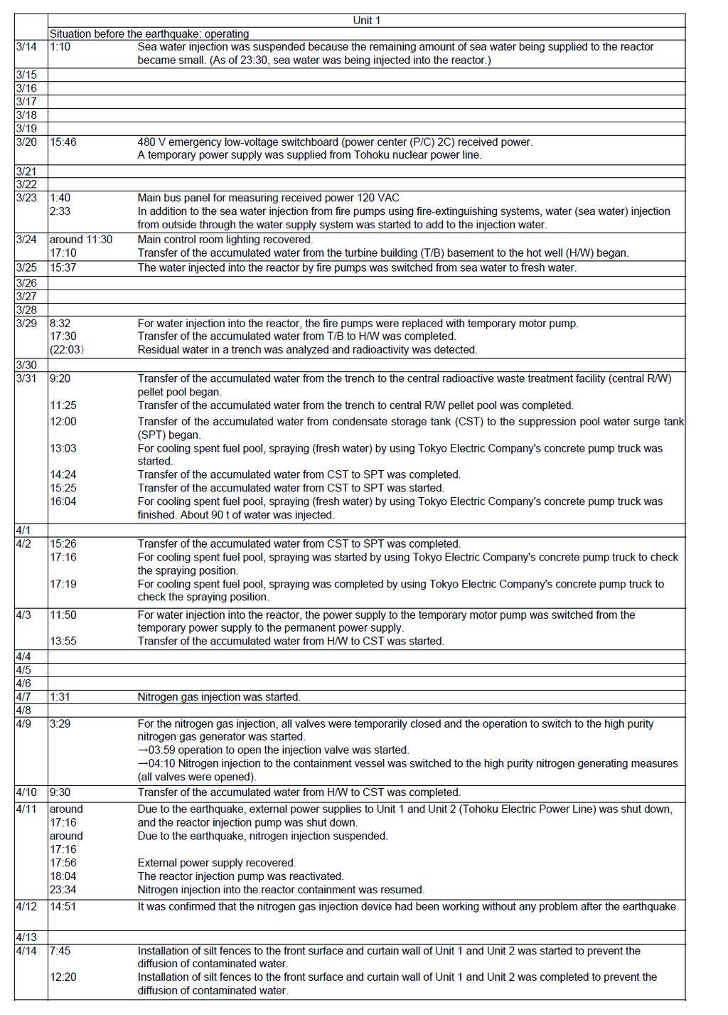
33 4. Occurrence and progression of the accident at the Fukushima NPSs (1) Overview of the chronology from the occurrence of the accident to the emergency measures taken 1) Fukushima Daiichi NPS The earthquake which occurred at 14:46 on March 11, 2011 brought all of the Fukushima Daiichi NPS Units 1 through 3, which were in operation, to an automatic shutdown due to the high earthquake acceleration. Due to the trip of the power generators that followed the automatic shutdown of the reactors, the station power supply was switched to the offsite power supply. As described in Chapter III, the NPS was unable to receive electricity from offsite power transmission lines mainly because some of the steel towers for power transmission outside the NPS site collapsed due to the earthquake. For this reason, the emergency DGs for each Unit were automatically started up to maintain the function for cooling the reactors and the spent fuel pools. Later, all the emergency DGs except one for Unit 6 stopped because the emergency DGs, seawater systems that cooled the emergency DGs, and metal-clad switchgears were submerged due to the tsunami that followed the earthquake, and the result was that all AC power supply was lost at Units 1 to 5. At 15:42 on March 11, TEPCO determined that this condition fell under the category of specific initial events defined in Article 10 of the Act on Special Measures Concerning Nuclear Emergency Preparedness (hereinafter referred to as Nuclear Emergency Preparedness Act) and notified the national government, local governments, and other parties concerned. At 16:36 on the same day, TEPCO found the inability to monitor the water level in the reactors of Units 1 and 2, and determined that the conditions of Unit 1 and 2 fell under the category of an event that is unable to inject water by the emergency core cooling system as defined in Article 15 of the Nuclear Emergency Preparedness Act, and at 16:45 on the same day, the company notified NISA and other parties concerned of this information. TEPCO opened the valve of the IC System A of Unit 1 IC, and in an effort to maintain the functions of the IC, it continued to operate it mainly by injecting fresh water into its shell side. Immediately after the tsunami, TEPCO could not IV-33
34 confirm the operation of the RCIC system of Unit 2, but confirmed about 3:00 on March 12 that it was operating properly. Unit 3 was cooled using its RCIC system, and as a result, the PCV pressure and water levels remained stable. In order to recover the power supply, TEPCO took emergency measures such as making arrangements for power supply vehicles while working with the government, but its efforts were going rough. Later, it was confirmed around 23:00 on March 11 that the radiation level in the turbine building of Unit 1 was increasing. In addition, at 0:49 on March 12, TEPCO confirmed that there was a possibility that the PCV pressure of the Unit 1 had exceeded the maximum operating pressure and determined that the event corresponded to the event abnormal increase in the pressure in the primary containment vessel as defined in the provisions of Article 15 of the Nuclear Emergency Preparedness Act. For this reason, in accordance with Article 64, Paragraph 3 of the Reactor Regulation Act, the Minister of Economy, Trade and Industry ordered TEPCO to reduce the PCV pressure of Units 1 and 2. At 5:46 on March 12, the company began alternative water injection (fresh water) for Unit 1 using fire engines. (The conceptual diagram of alternative water injection using fire engines is shown in Figure IV-4-1.) In addition, TEPCO began preparations for PCV venting because the PCV pressure was high, but the work ran into trouble because the radiation level in the reactor building was already high. It was around 14:30 on the same day that a decrease in the PCV pressure level was actually confirmed. Subsequently, at 15:36 on the same day, an explosion considered as a hydrogen explosion occurred in the upper part of the Unit 1 reactor building. Meanwhile, the RCIC system of Unit 3 stopped at 11:36 on March 12, but later, the HPCI system was automatically activated, which continued to maintain the water level in the reactor at a certain level. It was confirmed at 2:42 on March 13 that the HPCI system had stopped. After the HPCI system stopped, TEPCO performed wet venting to decrease the PCV pressure, and fire engines began alternative water injection (fresh water) into the reactor around 9:25 on March 13. In addition, PCV venting was performed several times. As the PCV pressure increased, PCV venting was performed several times. As a result, the PCV pressure was decreased. Subsequently, at 11:01 on March 14, an explosion that was considered as a hydrogen explosion occurred in the upper part of the reactor building. At 13:25 on March 14, TEPCO determined that the RCIC system of Unit 2 had stopped because the reactor water level was decreasing, and began to reduce the IV-34
35 RPV pressure and inject seawater into the reactor using fire-extinguishing system lines. TEPCO continued to cool the reactor core using the fire pumps loaned by a fire department. The wet venting line configuration had been completed by 11:00 on March 13, but the PCV pressure exceeded the maximum operating pressure. At 6:00 on March 15, an impulsive sound that could be attributed to a hydrogen explosion was confirmed near the suppression chamber (hereinafter referred to as S/C), and later, the S/C pressure decreased sharply. The total AC power supply for Unit 4 was also lost due to the earthquake and tsunami, and therefore, the functions of cooling and supplying water to the spent fuel pool were lost. Around 6:00 on March 15, an explosion that was considered as a hydrogen explosion occurred in the reactor building, damaging part of the building severely. At 22:00 on March 15, in accordance with Article 64, Paragraph 3 of the Reactor Regulation Act, the Minister of Economy, Trade and Industry ordered TEPCO to inject water into the spent fuel pool of Unit 4. On March 20 and 21, fresh water was sprayed into the spent fuel pool of Unit 4. On March 22, a concrete pump truck started to spray seawater onto the pool, followed by the spraying of fresh water instead of seawater, which began on March 30. On March 17, a Self-Defense Forces helicopter sprayed seawater into the spent fuel pool of Unit 3 from the air. Later, seawater was sprayed into the pool using high-pressure water-cannon trucks of the National Police Agency s riot police and fire engines of the Self-Defense Forces. From March 19 to March 25, Tokyo Fire Department, Osaka City Fire Bureau and Kawasaki City Fire Bureau, that were dispatched as Emergency Fire Response Teams, sprayed seawater for five times by using seawater supply system against fire and squirt fire engines. In addition, Yokohama City Fire Bureau, Nagoya City Fire Bureau, Kyoto City Fire Bureau and Kobe City Fire Bureau dispatched their fire engines to Fukushima Daiichi NPS or in readiness. Niigata City Fire Bureau and Hamamatsu City Fire Bureau assisted to set up large-scale decontamination system. Later, the concrete pump truck started to spray seawater into the spent fuel pool of Unit 3 on March 27 and into the spent fuel pool of Unit 1 on March 31. The total AC power supply for Unit 5 was also lost due to the earthquake and tsunami, resulting in a loss of the ultimate heat sink. As a result, the reactor pressure continued to increase, but TEPCO managed to maintain the water level and pressure by injecting water into the reactor by injecting water into the reactor by operating Make-Up Condensing Water Pump after the power was supplied IV-35
36 from Unit 6. Later, the company activated a temporary seawater pump, bringing the reactor to a cold shutdown condition at 14:30 on March 20. One of the emergency DGs for Unit 6 had been installed at a relative high location, and as a result, its functions were not lost even when the NPS was hit by the tsunami, but the seawater pump lost all functionality. TEPCO installed a temporary seawater pump while controlling the reactor water level and pressure by injecting water into the reactor and reducing the reactor pressure on a continuous basis. By doing this, the company recovered the cooling functions of the reactor, thus bringing the reactor to a cold shutdown condition at 19:27 on March 20. After the accident, seawater was used for cooling the reactors and the spent fuel pools for a certain period of time, but the coolant has been switched from seawater to fresh water with consideration given to the influence of salinity. 2) Fukushima Daini NPS Units 1 through 4 of the Fukushima Daini NPS were all in operation but automatically shutdown due to the earthquake. Even after the occurrence of the earthquake, the power supply needed for the NPS was maintained through one of the three external power transmission lines that had been connected before the disaster. (Incidentally, the restoration work for another line was completed at 13:38 on March 12, enabling the NPS to receive electricity through two external power transmission lines.) Later, the tsunami triggered by the earthquake hit the NPS, making it impossible to maintain reactor cooling functions because the seawater system pumps for Units 1, 2, and 4 could not be operated. For this reason, at 18:33 on March 11, TEPCO determined that a condition had occurred that fell under the category of events specified in Article 10 of the Nuclear Emergency Preparedness Act and notified the national government, local governments, and other parties concerned of this information. Later, since the temperature of the suppression chamber exceeded 100 C, and the reactor lost its pressure suppression functions, the company determined that an event where pressure suppression functions are lost defined in Article 15 of the Nuclear Emergency Preparedness Act had occurred at Unit 1 at 5:22 on March 12, at Unit 2 at 5:32 on the same day, and at Unit 4 at 6:07 on the same day, and notified the Nuclear and Industrial Safety Agency and other parties concerned of this information. Units 1, 2 and 4 of the Fukushima Daini NPS recovered their cooling functions due to the restoration work that followed the earthquake because the offsite power supply was maintained, and the metal-clad switchgears, DC power supply, and IV-36
37 other facilities were not submerged. As a result, Unit 1 was brought to a cold shutdown condition, in which the temperature for reactor coolants goes down below 100 C, at 17:00 on March 14, Unit 2 at 18:00 on the same day, and Unit 4 at 7:15 on March 15. Unit 3 was brought to a cold shutdown condition at 12:15 on March 12 without losing reactor cooling functions and suffering other kinds of damage. Figure IV-4-1 Conceptual Diagram of Alternative Water Injection Using Fire Engines IV-37
38 5. Situation of Each Unit etc. at Fukushima NPS The outline of the accident at Fukushima NPS has been given in Chapter 4. This accident involved a total loss of the AC power supply, so after the tsunami invasion, we were only able to get extremely limited parameter information. This section covers the parameter information we have been able to get to this point, under these very difficult conditions. In addition, in order to supplement this limited information, TEPCO carried out analysis and evaluation of reactor situation of Unit 1, Unit 2 and Unit 3 using MAAP, which is a Severe Accident Analysis Code, based on gained operating records and parameters. The results were reported to NISA on May 23. NISA carried out a cross-check by using another severe Accident Analysis Code, MELCOR in order to conduct a cross-check for validation of TEPCO s analysis with the assistance of Incorporated Administrative Agency Japan Nuclear Energy Safety Organization in order to confirm the adequacy of the analysis and evaluation. The report of analysis and evaluation conducted by Tokyo Electric Power Company is shown in Appended Reference IV-1, and analytic results by cross-check are shown in Appended Reference IV-2. Note that this parameter information was left behind in the Main Control Room and other areas after the accident and took some time to recover, so TEPCO made it public on May 16, along with reporting it to NISA. In addition, based on these analysis results, we have evaluated the event progress of this accident and made some estimates in areas such as the RPV, PCV, etc. situation regarding their relationship with changes over time and the events that occurred. Our evaluation of the development of events regarding the nuclear reactors for each unit at Fukushima NPS is written up as shown below. (1)We sorted out the plant information we have obtained as of the current moment and summarized it in chronological order. (2)We need to check the reliability of the parameter information etc. we obtained in order to evaluate the accident event progress, so this was considered based on the relationships with the performance of each plant operation, the overall behavior, the parameter IV-38
39 information, and so on. (3)Based on the conditions we considered in (2), we carried out a Severe Accident analysis, and analyzed the event development of the reactor accidents. (4)In order to evaluate RPV, PCV, etc., we first estimated the RPV, PVC, etc. situation when they were relatively stable. Then we used the estimated event progress to estimate the RPV, PCV, etc. situation as it changed with time. (5)We carried out a comparative consideration from the analysis in (3) and the RPV, PCV, etc. estimate results in (4). Then we evaluated how the series of events of accident progressed. In terms of events outside the reactor, in our summary in (1) we sorted out the related situations. In addition, we also analyzed the explosion damage to the reactor building in Unit 4 of the Fukushima Daiichi NPS. We then went on to sort out and sum up separately from the listings for each unit the fuel cooling work being done in the spent fuel pool and the situation (and treatment situation) for the pool water that has been confirmed in the trenches and other areas outside the building, and in the turbine building of each unit. Note that the estimates shown here are estimates of the possible situation based on the plant information we have been able to get at the present stage. We will need to update our deliberations as appropriate based on any supplemental information, such as details of parameter information or event information, and severe accident analysis results that reflect these. (1) Fukushima Daiichi NPS, Unit 1 1) Chronological arrangement of accident event progress and emergency measures a From the earthquake to the invasion of the tsunami As shown in Chapter 3, before the earthquake the power station was operating steadily at its rated power. Immediately after the earthquake struck, at 14:16 on March 11, the reactor of Unit 1 scrammed due to the excessive earthquake acceleration, and at 14:47 the control rods were fully inserted and the reactor became subcritical, and it was shutdown normally. In addition, the earthquake damaged the power reception breakers on the NPS side of the Okuma No. 1 and No. 2 Power Transmission Lines and other areas, so there was a loss of external power. This meant that two emergency diesel generators automatically started up. IV-39
40 At 14:47, the loss of the power supply to the instruments due to the loss of external power caused the failsafe to send a signal to close the Main Steam Isolation Valve (hereinafter referred to as MSIV), and the MSIV was closed down. Regarding this point, since the increase in the main steam flow volume that would be measured if the main steam piping was broken, was not confirmed in the Past Event Records Device, TEPCO judged that there were no breaks in the main steam piping and NISA considers that is a logical reason to make that judgment. The shutoff of the MSIV increased the RPV pressure, and at 14:52 the IC automatically started up. Next, in accordance with the operating manual for the IC, at 15:03 the IC was manually shut down. The manual notes that the temperature decrease rate for the RPV should be adjusted to not exceed 55 C/h. Moreover, the reactor pressure varied three times between 15:10 and 15:30, and TEPCO performed manual operations using only the A-system of the IC. Note that when the IC is operated, the steam is condensed and cooled, and is returned into the reactor as cold water through the reactor recirculation system. The records of the temperatures at the entrance to the reactor recirculation pump show three drops in temperature, so this is assumed to be the effects of the manual operation of the IC. Meanwhile, in order to cool the S/C, at approx. 15:07 and 15:10 the B and A systems of PCV spray system were activated. For the one hour that they remained following the earthwork, the HPCI records show no indications of any drop to the automatic activation water level (L-L) or any records of the HPCI being activated. b Effects from the tsunami At 15:37, the effects of the tsunami were felt, and the water, meaning that two emergency diesel generators stopped operation, and the emergency bus distribution panel was submerged, leading to all AC power being lost, affected both the seawater pump and the metal-clad switchgear of Unit 1. Unit 2 also suffered a loss of all AC power, so it was not possible to supply power from Unit 2. In addition, the loss of DC power functions meant that it was not possible to check the IV-40
41 parameter information. With the reactor water level no longer able to be monitored, and the water injection situation unclear, there was the possibility that no water was being injected, so at 16:36 TEPCO judged that this condition fell under the category of an event that is "unable to inject water by the emergency core cooling system as defined in Article 15 of the NEPA. Additionally, the loss of function of the component cooling system seawater pump meant that function of the component cooling system was lost, and the SHC was not able to be used, so it was not possible to relocate the decay heat of the PCV to the sea, the ultimate heat sink. c Emergency measures TEPCO opened the A system valve on the IC and used the diesel-driven fire pump (hereinafter referred to as D/D FP) to pump fresh water into the body of the IC etc., in an attempt to maintain the IC functions. However, according to the results from the valve circuit investigation TEPCO carried out in April, the degree the valve was open is not clear, so it is not possible to judge the extent to which the IC was functioning at this point in time (end of May). In addition, it has been confirmed that the radiation level inside the turbine building increased at around 23:00 on March 11. TEPCO confirmed that there was the possibility that the PCV pressure had exceeded the maximum operating pressure at 00:49 on March 12, and judged that this condition fell under the category of an event that is "unable to inject water by the emergency core cooling system as defined in Article 15 of the NEPA and informed NISA. As a result, at 6:50 on March 12, the Minister of Economy, Trade and Industry ordered the suppression of the PCV pressure in Units 1 and 2, in accordance with the provisions in Article 64, Paragraph 3 of the Reactor Regulation Act. TEPCO started pumping alternative water injection (fresh water) through fire pumps at 5:46 on March 12. Therefore, since cooling using the IC had stopped due to the failure of all AC power at 15:37 on March 11, that meant that there was a 14-hour-and-9-minute period when cooling using pumped water had stopped. TEPCO worked to vent the PCV in order to lower its pressure. However, since radiation inside the reactor building was already at the high radiation environment level, the work proceeded with difficulty. The motor-operated valve (MO valve) in the PCV vent line was manually opened to 25% at about 9:15 on March 12. In addition, workers headed to IV-41
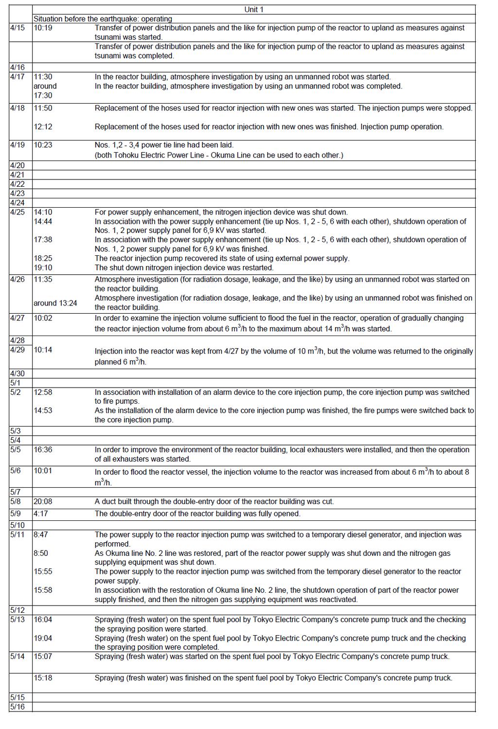
42 the site to open the air-operated valve (AO valve) manually but the radiation levels were too high. As a result, a temporary air pressurization machine was set up to drive the AO valve and the PCV vent was operated. TEPCO judged that the PCV vent had succeeded since the PCV pressure had been reduced by 14:30. d The building explosion and measures taken subsequently At 15:36 on March 12, an explosion, thought to be a hydrogen explosion, occurred in the upper part of the reactor building. The roof, and the outer wall of the operation floor as well as the waste processing building roof, were destroyed. Radioactive materials were released into the environment during these processes, thereby increasing the radiation dose in the area surrounding the site. According to TEPCO, the supply of 80,000 liters of fresh water ran out at around 14:53 on March 12, however it was unclear when the water injection stopped. At 17:55, in accordance with the provisions in Article 64, Paragraph 3 of the Reactor Regulation Act the Minister of Economy, Trade and Industry ordered TEPCO to take action to inject seawater to fill up the RPV. TEPCO started pumping in seawater using the fire-fighting lines at 19:04 on March 12. There was confusion in the lines of communication and command between the government and TEPCO regarding this injection of seawater. Initially, it was considered that it was suspended, but TEPCO announced on May 26 that it had not been stopped and injection had in fact continued based on a decision by the Power Station Director (in order to prevent the accident from escalating, the most important thing was to keep injecting water into the reactor). Later, on March 25, injection returned to using fresh water from the pure water tank. As of the end of May, the total amount injected was around 10,787 m 3 of fresh water, and around 2,842 m 3 of seawater, for a total of around 13,630 m 3. In addition, water was injected using the temporary electric pump from March 29, and on April 3 it was shifted to a stable water injection system by changing the power supply for this pump from a temporary supply to a permanent supply, and by other measures. On April 6, the Minister of Economy, Trade and Industry directed that TEPCO provide reports on the necessity of injecting nitrogen, how it would be done, and an evaluation of effects regarding safety, based on Article 67, Paragraph 1 of the Reactor Regulation Act. This was done as there was the possibility of hydrogen gas accumulating inside the IV-42
43 PCV. NISA accepted TEPCO s report, dated the same day, and directed them on three points, including ensuring safety through appropriate management of parameters, etc. when carrying out the nitrogen injection. TEPCO started nitrogen injection operations on April 7 and as of the end of May is still continuing them. To restore and enhance the power supply, TEPCO completed inspections and trial charging of the power receivers from Tohoku Electric Power Co. s Toden Genshiryoku Line on March 16, and as of March 20 had completed electricity access at the power center, ensuring an external power supply. As of March 23, cables were laid from the power center for the load needed. The connections are being established. Main time lines are shown in Table IV-5-1. In addition, parameters for the RPV pressure etc. are shown in Figs. IV-5-1 through IV ) Evaluation using the Severe Accident Analysis Code a Analysis and evaluation by TEPCO As a result of the analysis, while it was shown that the RPV had been damaged by melted fuel, when the results of temperature measurements for the RPV were taken into account, TEPCO considered that the most of the fuel was in fact being cooled at the bottom of the RPV. TEPCO estimated in this progress, the IC was not assumed to function following the tsunami and it was estimated that the fuel was uncovered for about three hours after the earthquake, with reactor damage starting one hour after that. Since then there was no water being injected into the reactor, the fuel had undergone core melting, due to its decay heat, and flowed to the lower plenum, then about 15 hours after the earthquake it started to damage the RPV. The radioactive materials contained in the fuel just before the accident were released into the RPV as the fuel was damaged and melted, and the analysis was carried out for the leakage assumed from PCV with the increase of PCV pressure, and almost all the noble gases were vented out into the environment. The ratio of released radioactive iodine to the total iodine contained (hereinafter referred to as release ratio) was IV-43
44 approximately 1% from the analysis result, and the release of other nuclides was less than 1%. b NISA s cross-check In the cross-check analysis, along with carrying out an analysis using the MELCOR code with the same conditions (basic conditions) as TEPCO used, an analysis was also performed using different conditions to those TEPCO assumed. A sensitivity analysis was carried out, such that the amount of alternative water injection was estimated by the relation of the pump discharge pressure with the RPV pressure. The cross-check of basic conditions showed largely the same trends. At around 17:00 on March 11 (two hours after the shock), the fuel began uncovered, and the core damage started within one hour. The PCV was damaged five hours after the shock, which is earlier than that of TEPCO s analysis, and the behavior of the RPV pressure was coherent with the pressure actually measured. As for release ratio of radioactive nuclides, the analytical results show about 1% of tellurium, about 0.7% of iodine and about 0.3% of cesium. However the release ratios are affected by the infection flow rates of seawater, the results may be changed by operation condition because the operation condition was not clear. 3) Evaluation of the Status of RPV, PCV, and the Equipment a Checking plant information Based on the plant information during the period between March 23 and May 31, when the plant was relatively stable, the status of the RPV and PCV was evaluated. Handling of the plant data during this period was considered as shown below. The standard water level is determined by the water level in the instrumentation piping and condensation tank in the PCV. While PCV pressure was high, there was a possibility that the reactor water level around the fuel was indicated higher than actual level, because high PCV temperature vaporize the water in the instrumentation piping and condensation tank in the PCV, hence those water level was indicated lower than actual level. This suggests that the reactor water level was indicating higher than normal. As a IV-44
45 result of recovering and correcting the standard water level for the reactor water level gauge on May 11, the water level was confirmed to have dropped below the fuel level, so it was not possible to measure the water level inside the RPV during this period either. The RPV pressure was considered as generally showing the actual pressure as the A and B system measurements matched until around March 26. However, after that the B system showed a rising trend, and so due to the condition estimates shown in the next section the B system was removed from evaluation consideration as it was no longer matching the D/W pressure. The RPV temperature showed different figures for each of the two water nozzle systems, but the system that was hovering around 120 C, matching the RPV pressure, was referenced as the temperature of the atmosphere in the RPV, and the data showing the higher temperatures was referenced as the metal temperature of the RPV itself. The plant data until March 22 was handled as follows. The reactor water levels around the fuel may have been indicating higher reactor water levels, as noted above. It was decided that water levels would not be referenced as it was not possible to judge the point at which the indications became inaccurate. The RPV pressure was referenced as generally showing the actual pressure for the A system, as, although both the A and B system figures matched after March 17, prior to that date the A system had also been changing continuously. It was difficult to confirm the actual changes in the D/W pressure in the PCV as the information from TEPCO was sporadic, but it was decided to assume it based on event information such as equipment operation, etc. b Estimates of the RPV, PCV, etc. status during the relatively stable period -Status of the RPV boundary The amount of water injected into the RPV by May 31 was estimated at approx. 13,700 tons based on information from TEPCO, but the total amount of steam generated from IV-45
46 the start of water injection was approx. 5,100 tons, as the water was evaluated with a larger estimate of decay heat using the evaluation formula for decay heat. If the pressure boundary could be ensured, then at minimum there would remain a difference of approx. 8,600 tons. The capacity of the RPV, even in the larger estimates, is about 350 m 3, so it is thought that the injected water is evaporated in the RPV and that there was not only leakage of steam, but of liquid as well. The injection of water into the RPV was done using a feed water nozzle, and initially pooled up outside the shroud, then flowed into the bottom of the RPV through the jet pump diffusers. The fuel has been considered as cooled, and at the present moment it is estimated that the injected cooling water is that which has leaked to the RPV bottom. In the present state, it is thought that steam continues to escape from the gas phase part of the RPV, but the RPV pressure is higher than the D/W pressure, so it is assumed that the opening is not large. However, the pressure changes after March 23 are changing in parallel with the changes in PCV pressure, so the possibility cannot be denied that there is a problem with the measurements. -Status of the RPV interior (reactor status, water level) As a result of increasing the amount of water injected when the injection was changed from the feed water line on March 23 the temperature of the RPV bottom dropped from being higher than the measurable maximum (greater than 400 C), but after the injection water amount was dropped, temperatures in some areas increased, so it is thought that the fuel is inside the RPV. As a result of recovering and correcting the standard water level for the water level gauge in the reactor on May 11, it was confirmed that the water level was lower than the fuel. Therefore, at the present moment it is estimated that the fuel has melted and an considerable amount of it is lying at the bottom of the RPV. However, there is a possibility that the bottom of the RPV was damaged and some of the fuel might have dropped and accumulated on the D/W floor (lower pedestal). The temperature of part of the RPV (the feed water nozzles, etc.) is higher than the saturation temperature for the PRV pressure, so at the present stage it is estimated that part of the fuel is not submerged in water, but is being cooled by steam. -PCV status IV-46
47 On March 12 the D/W pressure reached its highest level of approx. 0.7 MPag, exceeding the PCV maximum working pressure (0.427 MPag), and on March 23 the D/W temperature exceeded the measurable maximum (greater than 400 C). From these and other issues it is estimated at the present stage that the functions of the gasket on the flange section and the seal on the penetrating section have weakened. The inclusion of nitrogen, which started on April 7, was measured to increase the pressure by approx MPa, so at that stage it was estimated that the leakage rate from the D/W was approx. 4%/h. No major changes have been confirmed in the PCV status since then. Up until the inclusion of nitrogen on April 7, the D/W pressure and the S/C pressure were almost the same, and the S/C pressure dropped from being 5 kpa higher than the D/W pressure to being the same pressure several times up until April 3.Therefore, at the present stage it is estimated that the vent pipes and the vacuum breakers between the D/W and the S/C were not submerged. At present, TEPCO is continuing with its considerations in order to estimate the water level in the D/W. While the S/C pressure dropped after March 23, once it briefly reached approx. 0.3 MPag, a positive pressure state was measured for some time, and at the present stage it is estimated that there is no major damage to the S/C. 4) Estimation of the conditions of the RPV, PCV, and other components during times that variation with time was apparent The basic means of cooling the reactor after the MSIV is closed are cooling via the IC and water injection via the HPCI. However, there were few records of the operating conditions of these systems following arrival of the tsunami. Furthermore, the radiation dose rose in the turbine building at around 23:00 on March 11 and there was an unusual rise in pressure in the PCV at around 0:49 on March 12. Therefore, these conditions suggest that the RPV had been damaged before 23:00 on March 11 to increase the pressure and temperature of the PCV significantly, which led to the leakage from the PCV. Similarly, the information, written on the whiteboard in the central control room, of the increased indication of the radiation monitor when the outer air lock was put on at 17:50 on March 11 suggest that core damage was then starting. Analysis is required from here on to confirm the degree to which IC and HPCI were functioning that includes detailed investigation and analysis of the conditions of each component. IV-47
48 Although alternative water injection was commenced at 5:46 on March 12, the RPV water level reading dropped at around 7:00 and has yet to recover. Due to poor reliability of the water gauge, analysis is required from here on by detailed investigation and analysis that covers the relationship between the water injection operations and the following pressure behavior. As the D/W pressure in the PCV showed a tendency towards dropping slightly at around 6:00 on March 12 prior to wet vent operations, it is possible that there was a leak in the PCV. A drop in D/W pressure was also likely to have occurred after a temporary air compressor was installed to drive the pneumatic valves (AO valves) and wet vent operations were carried out at around 14:00 on March 12. However, when D/W pressure measurement recommenced at around 14:00 on March 13, the pressure has risen to 0.6 MPag and the PCV vent line had closed due to an unknown cause. Emissions may have restarted at 18:00 when pressure started dropping again. On March 13, RPV pressure dropped to 0.5 MPag and reversed position with D/W pressure. However, detailed examinations cannot be conducted due to lack in data of both pressures. 5) Evaluation of accident event development Regarding development of the Unit 1 accident event, from analyses conducted to date, it is likely that the IC stopped working when the tsunami hit, causing damage to the reactor from early on, and that by the time when the injection of sea water started into the reactor, the core had melted and moved to the bottom of the RPV. From the balance of the amount of water injected and the volume of vapor generated from decay heat, it is likely that the water injected into the RPV was leaking. Considering the results of RPV temperature measurements, it is likely that a considerable amount of the fuel cooled in the bottom of the RPV. Concrete details of the explosion in the reactor building are unclear due to constraints in checking conditions inside the building. In addition to severe accident analysis, numerical fluid dynamics analysis was also carried out. Results of these analyses showed likelihood that gasses including hydrogen produced from a reaction inside the reactor between water IV-48
49 and zirconium of the fuel cladding were released via leaks in the RPV and PCV, so that only hydrogen that reached the detonation zone accumulated in the space in the top of the reactor building and caused the explosion. In the waste processing building, in addition to damage caused by the blast, it is possible that there was an inflow of hydrogen via the part through which the piping runs. At this point, the degree to which individual equipment was actually functioning is unclear, so that it is also impossible to determine the status of progress of the event. However, the results of the severe accident analysis suggests that the radioactive materials emitted to the environment by the leakage and the subsequent wet vent from the PCV on the dawn of March 12. It is currently estimated that at that time, most of the noble gases in the content within the reactors, about 0.7% of the total radioactive iodine, and about 0.3% of the total cesium were emitted. IV-49

50 Table IV-5-1 Fukushima Daiichi NPS, Unit 1 Main Chronology (Provisional) * The information included in the table is subject to modifications following later verification. The table was established based on the information provided by TEPCO, but it may include unreliable information due to tangled process of collecting information amid the emergency response. As for the view of the Government of Japan, it is expressed in the body text of the report. IV-50
51 IV-51
52 IV-52
53 1.6 MPag B-system reactor pressure (MPag) B 系原子炉圧力 (MPag) D/W pressure (MPag) D/W 圧力 (MPag) Reactor water level by the reactor fuel range(a)(mm) 原子炉炉水位 ( 燃料域 )(A)(mm) S/C pressure (MPag) S/C 圧力 (MPag) A-system reactor A 系原子炉圧力 (MPag) pressure (MPag) /23 4/2 4/12 4/22 5/2 5/12 5/22 6/1 Reactor water level by A-system reactor B-system reactor D/W pressure (MPag) S/C pressure (MPag) 原子炉水位 the reactor ( fuel 燃料域 )(A) A pressure 系原子炉圧力 (MPag) B pressure 系原子炉圧力 (MPag) D/W 圧力 (MPag) S/C 圧力 (MPag) range(a) ( ) 500 (m 3 /h) Water nozzle N4B end temperature ( C) 給水ノズルN4B 終端温度 ( ) RPV lbottom temperature ( C) RPV 下部温度 ( ) Injection water flow rate (m 3 /h) 注水流量 (m3/h) /11 3/21 3/31 4/10 4/20 4/30 5/10 5/20 5/30 0 Figure IV-5-1 Changes in major parameters [1F-1] (From March 11 to May 31) IV-53
54 MPag S/C pressure (MPag) S/C 圧力 (MPag) Reactor water level by the reactor fuel range (A)(mm) 原子炉水位 ( 燃料域 )(A)(mm) A-system reactor B-system reactor D/W pressure (MPag) A 系原子炉圧力 (MPag) B 系原子炉圧力炉圧 (MPag) D/W 圧力 (MPag) pressure (MPag) pressure (MPag) /11 3/12 3/13 3/14 3/15 3/16 3/17 3/18 3/19 3/20 3/21 3/22 3/23 Reactor water level by the A-system reactor B-system reactor reactor 原子炉水位 fuel ((A) 燃料域 )(A) A pressure 系原子炉圧力 (MPag) pressure B 系原子炉圧力 (MPag) D/W pressure (MPag) D/W 圧力 (MPag) S/C pressure (MPag) S/C 圧力 (MPag) ( ) 500 (m 3 /h) RPV bottom temperature ( C) RPV 下部温度 ( ) Water nozzle N4B end 給水ノズルN4B 終端温度 ( ) temperature ( C) Injection 注水流量 water flow (m3/h) rate (m3/h) /11 3/12 3/13 3/14 3/15 3/16 3/17 3/18 3/19 3/20 3/21 3/22 3/23 Figure IV-5-2 Changes in major parameters [1F-1] (From March 11 to March 23) IV-54
55 1.6 MPag B-system reactor pressure (MPag) B 系原子炉圧力 (MPag) A-system reactor A 系原子炉圧力 (MPag) pressure (MPag) Reactor water level by the reactor fuel range(a)(mm) 原子炉炉水位 ( 燃料域 )(A)(mm) D/W pressure (MPag) D/W 圧力 (MPag) S/C pressure (MPag) S/C 圧力 (MPag) /23 4/2 4/12 4/22 5/2 5/12 5/22 6/1 Reactor water level by the A-system reactor B-system reactor D/W pressure (MPag) S/C pressure (MPag) 原子炉水位 reactor fuel ( 燃料域 range )(A) (A) A pressure 系原子炉圧力 (MPag) B pressure 系原子炉圧力 (MPag) D/W 圧力 (MPag) S/C 圧力 (MPag) ( ) 500 (m 3 /h) Water nozzle N4B end temperature ( C) 給水ノズルN4B 終端温度 ( ) RPV lower RPV 下部温度 temperature ( ) ( C) Injection water flow rate (m 3 /h) 注水流量 (m3/h) /23 4/2 4/12 4/22 5/2 5/12 5/22 6/1 Figure IV-5-3 Changes in major parameters [1F-1] (From March 23 to May 31) IV-55
56 (2) Fukushima Daiichi NPS Unit 2 1) Chronological arrangement of accident event progress and emergency measures a Between the earthquake occurrence and invasion of the tsunami As noted in number 3 of this chapter, steady operation of rated thermal power was being carried out prior to the earthquake. At 14:47 on March 11 following the earthquake occurrence, scram (automatic shutdown) was achieved due to large earthquake acceleration. At the same time, all control rods were fully inserted, the reactor became sub-critical and normal automatic shut down was achieved. The external power supply was lost as a result of the earthquake, due to damage incurred to the receiving circuit breakers of the station at the Okuma No. 1 and No. 2 power transmission line. This resulted in automatic startup of the two emergency DGs. At 14:47, the instrumentation lost power as a result of loss of external power supply, activating the MSIV closure signal as a fail-safe and causing the MSIV to close. Regarding closure of the MSIV, TEPCO determined that there was no rupture of the main steam piping, as we could not verify an increase in steam flow from the transient recorder records that would be have been observed if the main steam piping had ruptured. NISA considered this judgment reasonable. Closure of the MSIV led to a rise in RPV pressure. In accordance with the Procedures, the RCIC was activated manually at 14:50, but shut down at 14:51 due to a high reactor water level. This led to a drop in the water level, but the RCIC was again manually activated at 15:02 causing a rise in the water level. A high reactor water level was achieved at 15:28 causing the reactor RCIC to shut down automatically. The RCIC was again manually activated at 15:39. Between 22:00 on March 11 and 12:00 on March 14, the reactor water level reading (fuel range) remained stable at a level (+3000 mm or more) which maintained sufficient depth from the Top of Active Fuel (hereinafter referred to as TAF). Reactor pressure was controlled by closing and opening of the SRV. As operation of the SRV and RCIC led to a rise in the S/C temperature, the RHR pumps IV-56
57 were started in succession from 15:00 to 15:07 to cool the S/C water. This is verified by suppression of the temperature rise from around 15:00 to around 15:20 on the same day as shown in the temperature chart of the S/C. There are no records of operation of any emergency core cooling equipment aside from the activation of the RHR pumps to cool the S/C until the occurrence of the station blackout. This was likely because the reactor water level did not drop to the point (l-2) at which other equipment is automatically activated, and TEPCO state that they did not activate such equipment manually. b Impact from the tsunami The abovementioned S/C then showed a tendency towards a rise in temperature from 15:30, and the RHR pumps were successively shut down from around 15:36. This is thought to be due to a loss in functioning caused by the tsunami. At this time, the Unit was affected by the tsunami, the two emergency DGs stopped operating due to flooding and submergence of the seawater pump for cooling, the power distribution panel, and the emergency bus bar, and a station blackout was resulted. Furthermore, information on parameters could not be verified due to a loss in direct electrical current functionality. Loss in functionality of the RHR sea water pump led to a loss in RHR functionality, and the decay heat could not be transferred to the sea water that acted as the final heat sink. c Emergency measures At 22:00 on March 11, observation of the reactor water level was achieved. As of the day, it is presumed that the water injection was achieved by the RCIC since the water level was observed stable. However, reactor pressure is slightly lower than rated, at 6 MPa. From 4:20 to 5:00 on March 12, as condensate storage tank water level decreased and in order to control the S/C water level increase, the water source for the RCIC was switched from the condensate storage tank to the S/C so that the RCIC could continue injecting water. The reactor water level remained stable at a level which maintained sufficient depth from the TAF by 11:30 on March 14. From that point until 13:25 on IV-57
58 March 14, the reactor water level began to drop, at which point the RCIC was judged to have shut down. The level dropped to 0 mm (TAF) at 16:20 on the same day. In relation to this, TEPCO verified on-site that the RCIC was operating at 02:55 on March 12, and that the RCIC water source had switched from the condensate storage tank to the S/C, and through such measures among others, the RCIC was functioning by around 12:00 on March 14 to stabilize the reactor water level. TEPCO determined that there may have been a loss in reactor cooling functionality at 13:25 on the same day and made a notification pursuant to the provisions of Article 15 of NEPA. The RCIC is steam-driven, but the valves were operated through direct electrical currents. Although the time of RCIC functionality loss determined by TEPCO is more than 30 hours after operation start-up, given the actual constraints of battery capacity, it follows that functionality was maintained even after the battery run out. SRV opening operations and alternative water injection operations commenced at 16:34 on March 14, and a drop in reactor pressure was confirmed at around 18:00. At this time, the reactor water level also dropped. After that point, reactor pressure began to show a tendency towards rising, which is presumed to have caused the SRV to close due to problems in the air pressure used to drive the air operated valves (AOVs) and other problems. At 19:54 on March 14, the seawater injection into the reactor using fire engines was started. Water injection was therefore suspended for six hours and 29 minutes since 13:25 when the RCIC lost functionality. With regard to PCV vent operations to reduce pressure in the PCV, at 06:50 on March 12, TEPCO was ordered by the Minister of Economy, Trade and Industry in accordance with Article 64, Paragraph 3 of the Reactor Regulation Act to contain the PCV pressure. Based on this order, TEPCO began PCV vent operations, carrying out operations at 11:00 on March 13 and 00:00 on March 15, but a decrease in D/W pressure could not be verified. d Explosion and actions taken afterword At around 6:00 on March 15, the sound of an impact was heard which was considered to have resulted from a hydrogen explosion. No visible damage was observed at the reactor building, but it was confirmed that the roof of the waste processing building which is neighboring to the reactor building was damaged. During these processes, radioactive IV-58
59 material to be released into the environment, and as a result, the radiation dosage around the premises increased. At 10:30 on March 15, based on Article 64, Paragraph 3 of the Reactor Regulation Act, the Minister of Economy, Trade and Industry directed TEPCO to inject water into the reactor of Unit 2 as soon as possible and carry out a dry vent as it necessitates. With regard to the alternate water injection system, until March 26, sea water was injected into the reactor, but from March 26, fresh water was injected from a temporary tank. From March 27, the fire pumps were replaced by temporary motor-driven pumps, and from April 3, the temporary power source was replaced by an external power source to ensure the stable injection of water. The total amount of water injected as of May end was approx. 20,991 m 3 (fresh water; approx. 11,793 m 3, sea water: approx. 9,197 m 3 ). With regard to recovery and reinforcement of the power supply, TEPCO completed checking and the trial energizing of the facilities to receive power from the nuclear power line of Tohoku Electric Power Co., Inc. on March 16. From March 20, the Power Center received power to ensure the power supply from an external power source. On March 26, lighting in the Main Control Room was restored, and power was connected while the load soundness was being checked. In Table IV-5-2, these major events are arranged in a time-sequences with more details. Figs. IV-5-4 to 5-6 show the plant data such as RPV pressure. 2) Assessment using severe accident analysis codes a Analysis by TEPCO Results of the analysis by TEPCO show that when alternate injection water flow is small, RPV will be damaged due to the fuel melting. TEPCO assessed that considering the above results and the measured RPV temperature data obtained to date, that most of the fuel actually cooled at the RPV bottom. TEPCO judged that during this time, although RCIC operation was continued, water leakage from RPV was presumed to have occurred, based on PCV pressure behavior, that this leakage caused the RCIC to shut down. TEPCO supposed that the fuel was IV-59
60 uncovered for five hours from 13:25 on March 14 (75 hours after the Earthquake began) and that the core damage started two hours later. After that, assuming there was an outflow of alternate injection water due to insufficient maintenance of the reactor water level in the fuel region, the core likely melted, and the melted fuel moved to the lower plenum so that the RPV was damaged 109 hours after the Earthquake began. The leakage of radioactivity was analyzed assuming that the radioactivity contained in the fuel was released to RPV after fuel collapse and melting and that it leaked to the PCV. It is estimated that nearly all the noble gas was released to environment, and the release rates of iodine and other nuclides are less than about 1%. b Cross check analysis by NISA In the cross check analysis, NISA conducted analysis using MELCOR codes with the conditions that TEPCO analyzed (base case) and sensitivity analysis as a function of the injected water volume assuming the volume varies with RPV pressure in relation to the pump discharge pressure. In the cross check analysis of the base case, the results were roughly similar to TEPCO s results. At 18:00 on March 14 (75 hours after the Earthquake began), the fuel uncovering began, and core damage commenced within two hours. The time when the RPV was damaged in the cross check analysis was earlier than the time given in the TEPCO analysis, and was about five hours after the Earthquake began, and the PCV pressure behavior results are consistent with measured data. Results showed the release rate of radioactive materials to be about 0.4% to 7% for iodine nuclides, about 0.4% to 3% for tellurium nuclides, and about 0.3% to 6% for cesium nuclides. Release rates may change with operating conditions, as release rates vary with the sea water flow rate and the set operating conditions are unclear. 3) Evaluation of the conditions of the RPV, PCV, etc. a Verification of plant data First, the following studies the plant data from March 17 to May 31, during which the plant was relatively stable. Interpretation of plant data during this period is as follows: IV-60
61 With regard to the reactor water level around the reactor fuel, when the PCV pressure remained high, the PCV temperature was high. As a result, the water in the condensation tank and instrumentation piping in the PCV, whose water level is used as a reference water level, evaporated, causing the reference water level to drop. This may have caused the indicated reactor water level to be higher than the actual reactor water level. Since then, the reactor water level showed the same trend as that of Unit 1, and therefore, it was determined that during this period, the water level in the RPV was not measured properly. The measured RPV pressure in system A was consistent with that in system B, and it was determined that the indicated pressure was mostly correct. For the period during which negative pressure was indicated, the pressure was out of the measurable range of the pressure meter and determined to be not measured properly. Since March 27, the RPV temperature trend has been consistent with the amount of water injected, and it was determined that the indicated temperature was roughly correct. However, some data shows the temperature was kept constant, which is not consistent with other readings. Therefore, such data is not used for evaluation. With regard to the interpretation of plant data up to March 17, especially from March 14 to 15, the data fluctuated significantly, and could not be used for numerical values. The data was used as a reference for the rough understanding of fluctuations, along with event information such as the operation of equipment. b Presumed condition of the RPV, PCV, etc. when they were relatively stable -RPV boundary condition TEPCO estimated the amount of water injected into the RPV until May 31 to be 21,000 tons, but the amount of steam generated since the injection of water began was estimated to be about 7,900 tons although it was estimated by the decay heat evaluation method and the amount of decay heat was estimated to be a little larger than the actual amount. If the pressure boundary remains undamaged, at least about 13,100 tons of water should remain in the RPV. The volume of the RPV is estimated to be less than 500 m 3. Therefore, the injected water vaporized inside the RPV. In addition to the leakage of steam, liquid is also suspected of leaking. Water was injected into the RPV through the IV-61
62 recirculation water inlet nozzle, and flowed to the bottom of the RPV via the jet pump diffuser. Judging from the fact that the reactor fuel was kept cool, at this point, it is presumed that the injected water had leaked from the bottom of the RPV. From May 29 to May 30, water was injected through the recirculation water inlet nozzle and, in addition, water was injected through the feed-water nozzle. From around 17:00 on May 30, water was injected through the feed-water nozzle only. Since March 16, the RPV pressure has been kept around the atmospheric pressure, and equal to the D/W pressure of the PCV. At this point, it is presumed that the RPV has been connected to the PCV in the vapor phase area. -Condition of the inside of the RPV (core condition and water level) Since March 20 the RPV temperature has been measured when the amount of water injected increased. During most of the period after the start of measurements, the temperature was stable at around 100 C, and during most of the period after March 29 when the amount of water injected was decreased, the RPV temperature was around 150 C. Accordingly, at this point, it is presumed that a significant amount of the fuel remained in the RPV. However, there is a possibility that the bottom of the RPV was damaged and some of the fuel might have dropped and accumulated on the D/W floor (lower pedestal). Judging from the fact that the temperature in some part of the RPV is higher than the saturated temperature in relation to the RPV pressure, it is presumed that part of the fuel was not submerged and cooled by steam. -PCV condition On March 15, the D/W pressure exceeded the maximum useable pressure of the PCV (0.427 MPag) and increased to about 0.6 MPag. Accordingly, at this point, it is presumed that the sealing performance deteriorated at the gaskets of the flanges and the penetration parts. The D/W pressure is kept at around the atmospheric pressure (0 MPag) and it is presumed that the steam generated by decay heat is being released from D/W into the outside environment through these deteriorated parts. IV-62
63 Because, most of the time, the S/C pressure is not measured, at this point, it was difficult to estimate the condition of the inside of the S/C and the water level in the D/W based on the plant data. However, judging from the fact that high levels of contaminated water were found in the turbine building, at this point, it was presumed that the water injected into the RPV was leaking from the RPV through the PCV. Currently, TEPCO is studying how to estimate the water level in the D/W. 4) Presumption of the condition of the RPV, PCV, etc. as it changed with time According to TEPCO, early on March 12, the water source was switched to the S/C and the injection of water continued by the reactor core isolation cooling system (RCIC). On the morning of May 14, the water level was above the Top of Active Fuel (TAF). Accordingly, at this point, it was presumed that at least until then, the RCIC had functioned properly. It is also presumed that because the steam for driving the turbine of the RCIC was continuously released into the S/C gas phase on the morning of March 12, the S/C pressure increased, the steam flowed from the S/C into the D/W, and at around 12:00 on March 12, the D/W pressure increased. On the morning of March 14, the RPV pressure increased and the reactor water level dropped presumably because the RCIC malfunctioned, and the RPV pressure was about 7.4 MPag. Accordingly, it is presumed that the reactor water level further dropped after the SRV was activated. A report was received that the PCV was vented before that, but during part of the time, the PCV pressure did not decrease. There is a possibility that the RCIC did not fulfill its required function. To know to what extent the RCIC functioned, it is necessary to closely examine and analyze the condition of each component. At around 0:00 on March 15, the S/C pressure did not increase but the D/W pressure increased, and after that, there had been a significant difference between the D/W pressure and S/C pressure for a long time and they had been inconsistent with each other. It is unknown why this happened. In addition to these presumptions, the water level did not return to normal, and at around 0:00 on March 15, the readings on the PCV atmosphere monitoring system (hereinafter referred to as CAMS) for the D/W and S/C increased by three to four digits. Accordingly, it is presumed that the fuel was damaged at this time. In addition, TEPCO reported that from late afternoon on March 14, water was injected by fire trucks, but the water level IV-63
64 did not rise, and there is a possibility that they did not fulfill their required function because of the reactor pressure. To know what extent they functioned, it is necessary to closely examine and analyze the condition of each component. 5) Event development analysis and summarization of the events based on the presumptions of the condition of the RPV, PCV, etc. With regard to accident event progress in Unit 2, analyses carried out to date suggest that the loss in RCIC functionality caused damage to the reactor core, and that water injection may not have been sufficient as injection of seawater commenced at a time of high pressure in the reactor. As a result, insufficient cooling may have caused melting of the reactor core, and the melted fuel, etc, to transfer to the bottom of the RPV. Considering the balance of volume of injected water and volume of steam generated from decay heat, it is presumed that the water injected into the RPV is leaking. Considering the results of RPV temperature measurement, a significant amount of fuel is thought to have cooled in the bottom of the RPV. With regard to the sounds of an impact around the S/C, we cannot say anything for sure because we are limited in checking the site where the explosion was heard. In addition to severe accident analysis, we conducted numerical fluid dynamics analysis, and at this point, it is presumed that in the reactor, the hydrogen generated when zirconium used in the fuel cladding reacted with water flowing into the S/C when the SRV was opened, leaked from the S/C, and exploded in the torus room. With regard to the waste processing building, at this point, we cannot deny the possibility that it was damaged by the blast and the hydrogen flowed into it through the pipe penetrations etc. At this point, we cannot indentify to what extent each component functioned, and therefore, cannot determine how the events of the accident have developed. However, based on results of the severe accident analysis of the current situation, regarding the release of substances to the environment via a leak in the PCV up until the morning of March 15, it is estimated that nearly all the noble gas was released and the proportions released into the environment of iodine, cesium, and tellurium are approx. 0.4% to 7%, 0.3% to 6%, and 0.4% to 3%, respectively. IV-64
65 Table IV-5-2 Fukushima Daiichi NPS, Unit 2 Main Chronology (Provisional) * The information included in the table is subject to modifications following later verification. The table was established based on the information provided by TEPCO, but it may include unreliable information due to tangled process of collecting information amid the emergency response. As for the view of the Government of Japan, it is expressed in the body text of the report. IV-65
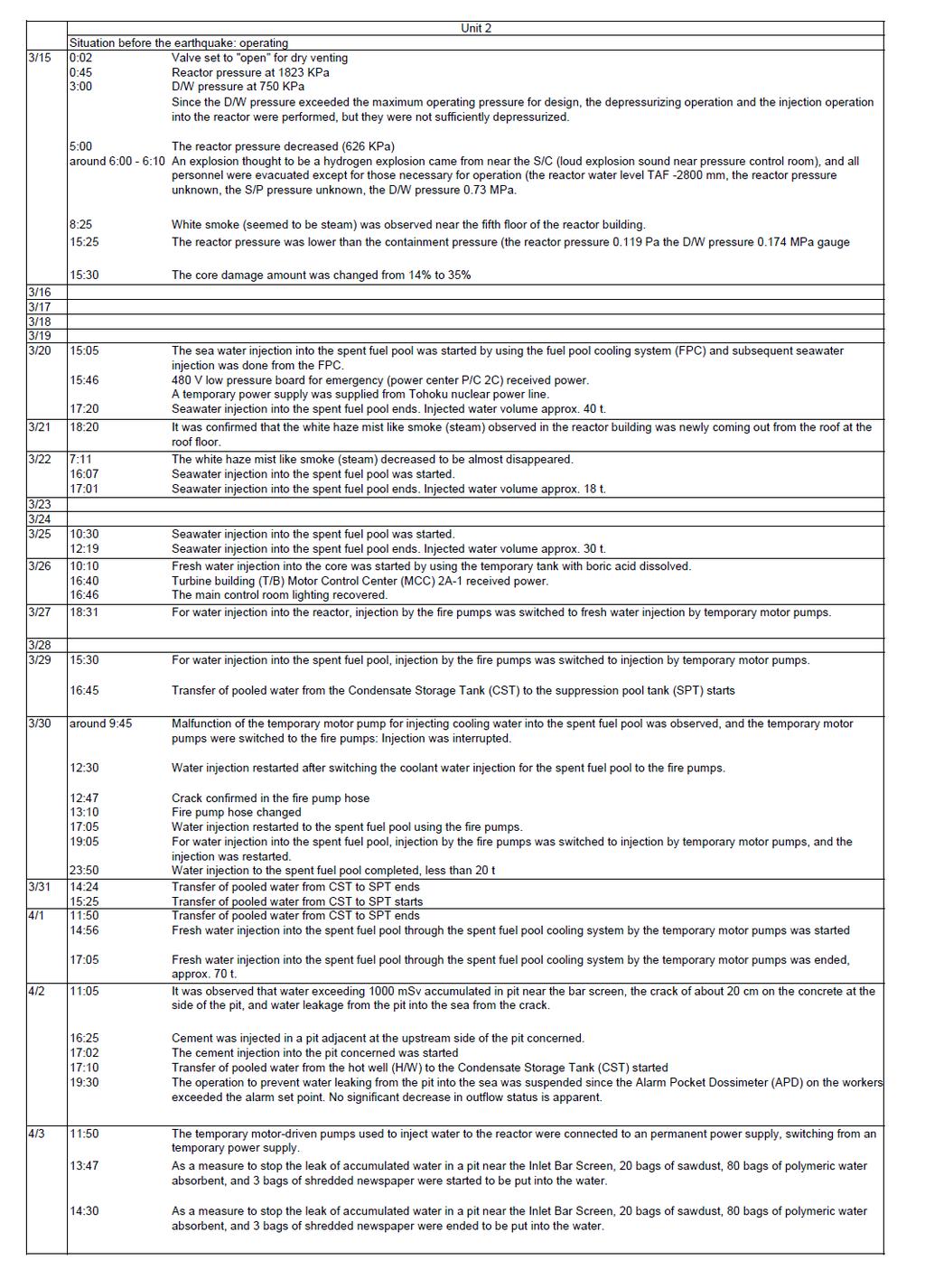
66 IV-66
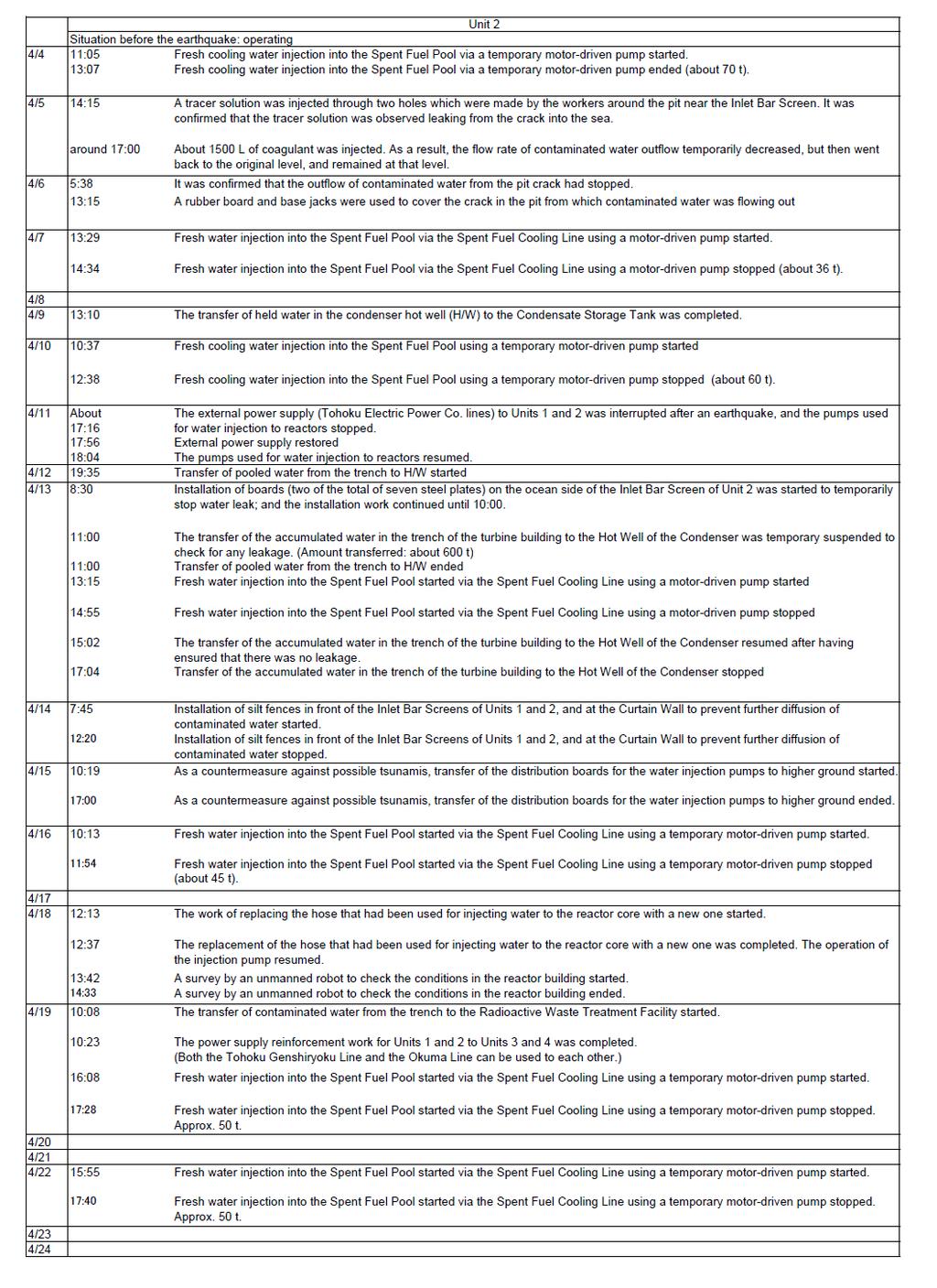
67 IV-67
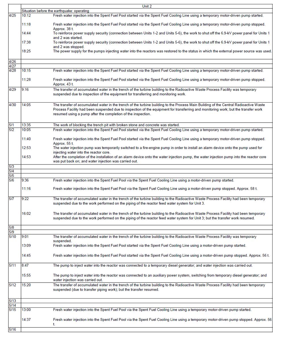
68 IV-68
69 9 8 MPag A-system reactor pressure (MPag) A 系原子炉圧力 (MPag) mm Reactor water level by the reactor fuel range (A)(mm) 原子炉炉水位 ( 燃料域 )(A)(mm) D/W pressure (MPag) D/W 圧力 (MPag) S/C pressure (MPag) S/C 圧力 (MPag) B-system B 系原子炉圧力 reactor (MPag) pressure (MPag) /11 3/21 3/31 4/10 4/20 4/30 5/10 5/20 5/30 6/9 Reactor water level by A-system D/W pressure S/C pressure B-system reactor 原子炉水位 the reactor ( fuel 燃料域 range )(A) A reactor 系原子炉圧力 pressure (MPag) D/W 圧力 (MPag) (MPag) S/C 圧力 (MPag) B pressure 系原子炉圧力 (MPag) (A) (MPag) 500 m3/h RPV support skirt temperature ( C) RPV 支持スカート温度 ( ) Water 給水ノズル温度 nozzle ( ) temperature ( C) RPV RPV ドレンパイプ上部温度 drain pipe upper ( ) temperature ( C) Injection 注水流量 water flow (m3/h) rate (m 3 /h) /11 3/21 3/31 4/10 4/20 4/30 5/10 5/20 5/30 6/9 Fig. IV-5-4 Changes in key parameters [1F-2] (From March 11 to May 31) IV-69
70 9 MPag mm Reactor water level by the reactor fuel range(a)(mm) 原子炉炉水位 ( 燃料域 )(A)(mm) A-system reactor pressure (MPag) A 系原子炉圧力 (MPag) D/W pressure (MPag) D/W 圧力 (MPag) S/C pressure S/C 圧力 (MPag) (MPag) /11 3/12 3/13 3/14 3/15 3/16 3/17 Reactor water level by A-system D/W pressure S/C pressure B-system 原子炉水位 the reactor ( fuel 燃料域 range )(A) reactor A 系原子炉圧力 pressure D/W (MPag) 圧力 (MPag) S/C (MPag) 圧力 (MPag) B reactor 系原子炉圧力 pressure (A) 500 m3/h Injection water flow rate (m 3 /h) 注水流量 (m3/h) /11 3/12 3/13 3/14 3/15 3/16 3/17 Fig. IV-5-5 Changes in key parameters [1F-2] (From March 11 to March 17) IV-70
71 MPag 0.4 mm Reactor water level by the reactor fuel range(a)(mm) 原子炉炉水位 ( 燃料域 )(A)(mm) B-system reactor pressure B 系原子炉圧力 (MPag) B(MPag) A-system reactor pressure (MPag) A 系原子炉圧力 (MPag) S/C S/C pressure 圧力 (MPag) (MPag) D/W pressure D/W 圧力 (MPag) (MPag) /17 3/27 4/6 4/16 4/26 5/6 5/16 5/26 6/5 Reactor water level by A-system reactor D/W pressure S/C pressure B-system reactor 原子炉水位 the reactor ( fuel 燃料域 range )(A) pressure A 系原子炉圧力 (MPag) (MPag) D/W 圧力 (MPag) S/C (MPag) 圧力 (MPag) B pressure 系原子炉圧力 (MPag) (A) 500 m3/h RPV support skirt temperature ( C) RPV 支持スカート温度 ( ) Water nozzle temperature ( C) 給水ノズル温度 ( ) RPV drain pipe upper temperature ( C) RPVドレンパイプ上部温度 ( ) Injection waterflow rate (m 3 /h) 注水流量 (m3/h) /17 3/27 4/6 4/16 4/26 5/6 5/16 5/26 6/5 Fig. IV-5-6 Changes in key parameters [1F-2] (From March 17 to May 31) IV-71
72 (3)Fukushima Daiichi NPS, Unit 3 1) Order of accident progress and provisional expedient (chronological sequence) a From the earthquake until the arrival of the tsunami As described in Chapter 3, the plant was in full power operation before the earthquakes. After the earthquakes hit, the nuclear reactor at Unit 3 scrammed at 14:47 on March 11 due to the great acceleration of the earthquakes and automatically shut down as all control rods were inserted to bring the reactor into subcritical. In addition to Okuma Line 3, which was powered off due to repair work started before the earthquake, the breaker at Shintomioka Substation tripped and the breaker for receiving electricity at the switchyard in the power station was damaged, disrupting the power supply from Okuma Line 4. By causing the loss of external power supply, two emergency DGs started automatically. At 14:48, the loss of power to instruments caused by the loss of external power supply triggered a closure signal at the main steam isolation valve (MSIV) in accordance with the fail-safe design. Regarding the closure of the MSIV, the Tokyo Electric Power Co., Inc. (TEPCO) considered that the main steam pipes did not rupture with the records of the flow rate of the main steam, which would be observed as the increase of the flow rate when the main steam piping breaks. The Nuclear and Industrial Safety Agency (NISA) also agrees that such a judgment would be reasonable. The closure of the MSIV resulted in increasing of RPV pressure and at 15:05, the reactor core isolation cooling system (RCIC) was manually activated as a precautionary measure. At 15:28, the pressure increase stopped due to the high water level in the reactor. b Effects of the tsunami At 15:38, as a result of the impact of the tsunami, two emergency DGs stopped operating and all AC power was lost due to the drenching/submersion of the cooling seawater pumps, the metal-clad switchgear and the emergency bus of Unit 3. IV-72
73 The inability to use the residual heat removal system seawater pumps meant the loss of residual heat removal system (RHR) functions, resulting in a failure to shift the decay heat in the PCV to the sea, the final heat sink. However, the DC bus of Unit 3 escaped being drenched. Power was not supplied through AC-DC transfer from the DC bus, but rather the backup storage batteries supplied power to the loads (RCIC valves, recorders, etc.) that required direct current for an extended time compared to those of other units. Because of the drawdown resulting from the shutdown of the RCIC at 15:25, the RCIC started again at 16:03 and stopped at 11:36 on March 12. The reason why the RCIC stopped at 11:36 on March 12 is unknown at this time, but the storage batteries for valve manipulation might have become exhausted as more than 20 hours had passed since the RCIC started operation. Afterwards, the HPCI started automatically at 12:35 on March 12 due to the low water level of the core and stopped at 2:42 on March 13. At that time, the plant-related parameters did not indicate any water level, and so the core coolant injection system stopped as the water level in the core was unknown. At 3:51, after more than one hour had passed since the HPCI stopped, the power was restored to the water level gauge, which showed that the water level for the reactor fuel was mm (TAF-1600 mm). It is thought that the HPCI stopped as a result of the lower reactor pressure. TEPCO judged that the situation corresponded to a loss of reactor coolant functions event stipulated according to the provisions of Article 15, NEPA for Nuclear Disaster and notified NISA and other parties in accordance with the requirements of the Act. c Reactor pressure changes The reactor pressure transitioned fairly stably after the scram, but at around 9:00 on March 12, the reactor pressure began to show larger fluctuations. From 12:30 to about 19:00, it decreased by more than 6 MPa. IV-73
74 From around 19:00 on March 12, the reactor pressure was being stable around one MPa, but from 2:00 to 2:30 on March 13, being decreased once and then increased to 7 MPa by around 4:00 on the same day. During the initial stage of this reactor pressure change, the HPCI was working. But when the HPCI stopped, the reactor pressure may have risen suddenly. Considering that the reactor pressure dropped for more than six hours from 12:30 on March 12, it is considered unlikely that a large-scale pressure leak occurred. Steam may have leaked from the HPCI, since the pressure began to drop at around the same time as the HPCI started and the reactor pressure began rising after the HPCI stopped. At around 9:00 on March 13, the reactor pressure dropped rapidly down to approximately 0 MPa. This may have occurred because of rapid depressurization resulting from the operation of the major steam SRV. d Emergency measures In order to lower the PCV pressure after the HPCI stopped at 2:42 on March 12, TEPCO carried out wet venting from 8:41 the same day. From approximately 9:25 on the same day, though TEPCO started injecting fresh water containing boric acid through the fire extinguishing system by using fire engines, the RPV water level still dropped. Even taking this injection into account, this meant that no injection had occurred for six hours and 43 minutes since the HPCI stopped. At 13:12 the same day, water injection was changed to seawater. To reduce the PCV pressure, wet venting was carried out at 5:20 on March 14. e Explosion at the building and subsequent measures An explosion, which was likely a hydrogen explosion, occurred at the upper part of the reactor building at 11:01 on March 14. The explosion destroyed the operation floor and all floors above it, the north and south external walls of the floor below the operation floor, and the waste processing building. At this time, radioactive materials were released into the atmosphere and the radiation dose in the vicinity of the site increased. IV-74
75 On March 25, fresh water from the pure water storage tank was once again used as an alternative injection to the reactor. As of the end of May, the total injection volume had reached approx. 20,625 m 3 (approx 16,130 m 3 of fresh water and approx. 4,495 m 3 of seawater). On March 28, reactor injection was performed by temporary motor-driven pumps, and on April 3, their power supply was switched to a permanent power supply. The injection system was thus shifted to a stable system. While verifying the integrity of load systems through the repair of the transformer at Shin Fukushima Substation and the bypass operation between Line 1 of the Yorunomori Line and Line 3 of the Okuma Line, the power supply has been gradually restored. On March 18, power supply was restored as far as the site metal-clad switchgear, and on March 22, the lighting of the main control room was restored. The main chronological sequence is shown in Table IV-5-3. Plant data, such as the RPV pressure, is shown in Figures IV-5-7 to IV ) Evaluation using severe accident analysis codes a Analysis by TEPCO When TEPCO s analysis showed that the flow volume of the alternative injection water was low, it resulted in damage to the RPV due to melted fuel. TEPCO has used these results in addition to the existing PRV temperature measurement results to evaluate that the greater part of the fuel has in fact been cooled at the bottom of the RPV. TEPCO estimated that during this process the reactor fuel was exposed for about four hours from 2:42 on March 13, when the HCPI stopped (about forty hours after the earthquake hit), and two hours later, damage to the core began. Later, as the reactor water level was not able to be maintained around the fuel, flow volume for the alternative water injection was assumed. The decay heat began melting the core and the melted fuel shifted to the lower plenum and then some 66 hours after the earthquake, it started to damage the RPV. IV-75
76 The analysis results show that, along with the damage to the core and the core melt of reactor fuel, the embedded radioactive materials were released into the RPV and moved to the S/C, with the noble gases almost all being released into the environment through PCV vent operation, and approximately 0.5% of the radioactive iodine was released. Note that TEPCO carried out an additional analysis, which assumed leakage from the HPCI steam system as the RPV and D/W pressures had dropped while HPCI was operating. The analysis results show that the RPV pressure changes and the D/W pressure changes were generally in alignment, but, including the problems with instrumentation, it is not possible to pinpoint the reason the RPV and D/W pressures dropped, nor their current status. b Crosscheck by NISA In the crosscheck analyses, NISA analyzed using the MELCOR codes based on the conditions (basic conditions) that TEPCO adopted. In addition, a sensitivity analysis and other analyses were carried out in terms of the relationship with the pump output pressure and determined that the injected water volume for the alternative water injection was in line with the RPV pressure. The crosscheck under basic conditions indicated nearly the same tendencies as seen by TEPCO. It showed that the fuel was exposed at about 13:08 (41 hours after the earthquake) and three hours later core damage started. The time period the RPV was damaged was about 79 hours after the earthquake. The analysis results show that the amount of radioactive materials was approx. 0.4% to 0.8% of radioactive iodine was released, and the other nuclides were approx. 0.3% to 0.6%. However, the released amount changes according to the settings for seawater injection flow amounts, etc., and the operating status is unclear, so there is the possibility that this will change depending on the operating status. Regarding the assumption by TEPCO of operational status for the high pressure water injection system, as there is no quantitative setting basis shown, it is difficult to evaluate what exactly has happened, and further investigation is required. However, regardless of the high pressure water injection system operating status, the reactor pressure has been restored due to stopping the high pressure water injection system and if the reactor IV-76
77 water level can be maintained, then there will be no major effects on the core status and of course no effects on the evaluation of core status. 3) Estimation of RPV and PCV situations a Confirmation of plant information The study was done on plant data obtained during the period from March 15 to May 31, when the plant was in a comparatively stable condition, and the plant data from this period was handled as shown below. An instruction may have been issued to maintain a higher water level in the fuel area since the PCV temperature was high when the PCV pressure was remaining at a high level, and the normal water level dropped due to the evaporation of water in the PCV condensation tank as well as the instrumentation piping. As Unit 3 showed the same tendency that Unit 1 later showed, the water level in the RPV was considered immeasurable. The RPV pressure was nearly equal to the measured values of the A and B systems, so it was considered to show a close approximation of the actual pressure. For the period when negative pressure was shown, it was considered to be within an error range as such pressure is immeasurable by the pressure gauge. After March 30, the RPV temperature stayed around 100 C in connection with the RPV pressure and so it was considered to generally show an actual temperature. However, some pieces of data showing high temperature values were excluded from the evaluation as they did not meet with the trend of other measured values. The plant data up to March 15, which is very limited, was added to the data from March 15 on, and excepting the data regarding the reactor water level, was referred to under the assumption that it reflected the actual situation. As stated above, there may have been an instruction to keep the water level high in the reactor fuel area. As it is impossible to determine when deviation from the instruction began to occur, only the changes in the situation were referred to roughly in considering information on equipment operation and so forth. IV-77
78 b Estimation of RPV and PCV situations during comparatively stable period -Situation of RPV boundary According to the information of the Tokyo Electric Power Co., Inc. (TEPCO), the total injection amount to RPV up to May 31 is considered to be about 20,700 tons. The total amount of vapor generated from the start of injection is about 8,300 tons when the decay heat is estimated on the outside in the decay heat evaluation formulation. If the pressure boundary is secured, a difference of about 12,400 tons at least may be kept there. As the capacity of RPV is 500 m 3 at most, the injected water may not only evaporate within RPV and leak as vapor, but also may leak as water. The injection to RPV was executed through the nozzles of recirculating water inlet and water supply equipment. The water injected through the nozzle of water supply equipment would gather once in the outside of shroud (from about 17:00 May 21 to about 23:00 May 28) and then would move to the bottom of RPV via the jet pump diffuser to cool the reactor fuel. The water is very likely to leak to outside at this portion. From about 23:00 May 29 and on, the injection was switched and continued only through the nozzle of water supply equipment. The RPV pressure has been close to the atmosphere pressure from March 22 and similar to the D/W pressure of PCV, and so it is now estimated that RPV seems to connect to PCV through the gas phase portion. -Situation in RPV (reactor core status and water level) Some RPV temperatures exceeded the measurable range (higher than 400 C) due to the lower injection flow rate caused by the increase of RPV pressure on March 20, but the temperature dropped through the securing of injection flow rate on March 24 and stayed around 100 C. Accordingly a considerable amount of reactor fuel may remain within the RPV. However, there is a possibility that the bottom part of the RPV was damaged and some of the fuel might have dropped and accumulated on the dry well floor (lower pedestal). IV-78
79 The temperature tends to rise in general from the beginning of May. Considering that it partially exceeds 200 C and is higher than the saturation temperature for the RPV pressure, part of reactor fuel may still remain unsubmerged and be cooled by vapor. -Status of PCV As the pressure of D/W and S/C exceeded the maximum operating pressure (0.427 MPag) of the PCV to reach about 0.5 MPag on March 13, it is assumed at this moment that the performance of the gaskets of flanges and the seals of penetrations deteriorated. The D/W pressure is maintained around the atmospheric pressure (0 MPag). Therefore, it is assumed at this moment that the vapor generated by decay heat may be released to the outside through D/W. As the pressure of gas phase portions of S/C stayed at a higher level than the atmospheric pressure and the D/W pressure is close to the atmospheric pressure, the temperature of water that flows from the lower part of D/W down to S/C is 100 C at a maximum. Accordingly, it is now estimated that the 0 MPag or higher pressure of the gas phase portions of S/C is due to noncondensable gasses. Right now, TEPCO is studying how to estimate the water level of D/W. 4) Estimation of situations of RPV, PCV and others at a given moment over time After the earthquake, water injection continued through the reactor core isolation cooling system (RCIC). Around 12:00 on May 12, the RCIC stopped operation. Alternatively, water injection was made through the high-pressure coolant injection system (HPCI) but the reactor pressure decreased and thus the reactor water level is estimated to have increased. Before dawn on the morning of March 13, however, the reactor pressure dropped and HPCI stopped operation. The stoppage of HPCI is estimated to have triggered the reactor pressure to exceed the operation pressure of about 7 MPa. But the main steam safety relief valve (SRV) is estimated to have been activated to release the vapor to S/C to maintain the pressure at around the 7 MPa level, during which time it is estimated that the reactor water dropped and the reactor fuel was damaged. IV-79
80 It is estimated that the main steam SRV opened to lower the reactor pressure, and at 9:25 on March 13 alternative injection was carried out and wet vent operation done in response to the increase in PCV pressure. It was reported that the alternative injection from fire engines was executed, but this measure could not demonstrate the required performance due to the relation with the reactor pressure, etc. as the water level has not been restored yet. More detailed investigations and analyses of the conditions/situations of equipment would be necessary in order to find out to what extent such measures worked. 5) Analysis of accident event progress Regarding the progress of events in the accident at Unit 3, previous analyses showed that the RCIC and HPCI ceased to function, so PCV spraying using fire engines and wet vent operation were carried out. In addition, there is the possibility that, based on the water level situation following the start of fresh water injection and RPV pressure reduction operations, not enough water was injected and it is estimated that the lack of sufficient cooling led to core melt, with the melted fuel moving down to the bottom of the RPV. From the balance between the injected water volume and volume of steam produced, it is estimated that the water injected into the RPV is leaking. Based on the RPV temperature measurement results, it is considered that a considerable amount of fuel is cooling on the RPV bottom. The situation of the reactor building after the explosion is not known in detail for certain yet due to the limited site verification. As a result of the execution of numerical fluid dynamic analysis in addition to the severe accident analysis, the release of the gas that contained the hydrogen generated through the reaction between zirconium in the clad of fuel rods and the water in the reactor might accumulate hydrogen sufficient enough to reach the detonation range in the upper space of reactor building to cause the explosion. Along with the explosion, the oil for the MG sets for the control of the rotating speed of recirculation pumps burnt concurrently at the heavily damaged west side of the 4th floor of reactor building. For the waste processing building, it cannot be denied now that it might be damaged not only by the blast waves but also by the explosion of the hydrogen that flew in through the piping penetrations. The high dose contamination that hinders works in the vicinity of the building was found on part of debris scattered by the explosion. The severe accident analysis, while it does not assume any leakage from the IV-80
81 PRV, suggests that it might be the result of radioactive materials that leaked from the PCV adhering to the reactor building structure, as the PCV maximum operating pressure was exceeded. As it is impossible to identify to what extent each system functioned actually, it is also impossible to determine the event progress situation at this moment. From the results of the severe accident analysis, however, it can be estimated that radioactive materials were released into the environment by the wet vent operation starting at noon on March 13, and almost all the noble gases in the core were released, and the iodine and cesium in the core were released at ratios of approx. 0.5% to 0.8% and approx. 0.3% to 0.6% respectively. IV-81
82 Table IV-5-3 Fukushima Daiichi NPS, Unit 3 Main Chronology (Provisional) * The information included in the table is subject to modifications following later verification. The table was established based on the information provided by TEPCO, but it may include unreliable information due to tangled process of collecting information amid the emergency response. As for the view of the Government of Japan, it is expressed in the main body of the report. IV-82
83 IV-83
84 IV-84
85 IV-85
86 IV-86
87 8 (MPag) A system: Reactor pressure (MPag) A 系原子炉圧力 (MPag) (mm) Reactor water level (reactor fuel range) (B) (mm) 原子炉水位 ( 燃料域 )(B)(mm) D/W pressure (MPag) SC pressure (MPag) D/W 圧力 (MPag) S/C 圧力 (MPag) B system: Reactor pressure (MPag) B 系原子炉圧力 (MPag) /11 3/21 3/31 4/10 4/20 4/30 5/10 5/20 5/30 6/9 Reactor water level A system: Reactor B system: Reactor D/W pressure S/C pressure (fuel 原子炉水位 range)(b) ( 燃料域 )(B) pressure A 系原子炉圧力 pressure B 系原子炉圧力 (MPag) D/W 圧力 (MPag) (MPag) S/C 圧力 (MPag) 425 m3/h RPV bottom temperature ( C) RPV 下部温度 ( ) RPV shell-side flange temperature ( C) RPV 胴フランジ温度 ( ) Water supply nozzle temperature 給水ノズル温度 ( C) ( ) Injection flow rate (m 3 /h) 注水流量 (m3/h) /11 3/21 3/31 4/10 4/20 4/30 5/10 5/20 5/30 6/9 Figure IV-5-7 Changes of Main Parameters (1F -3) (March 11 to May 31) IV-87
88 (MPag) 8 7 A system: A 系 Reactor 原子炉圧力 pressure (MPag) (MPag) (mm) Reactor water 原子炉水位 level (fuel ( 燃料域 range)(b)(mm) )(B)(mm) D/W pressure D/W 圧力 (MPag) (MPag) S/C S/C pressure 圧力 (MPag) (MPag) B 系 system: 原子炉圧力 Reactor (MPag) pressure (MPag) /11 3/12 3/13 3/14 3/15 Reactor water level (fuel A system: Reactor B system: Reactor D/W pressure S/C pressure range)(b) 原子炉水位 ( 燃料域 )(B) pressure A 系原子炉圧力 pressure B 系原子炉圧力 (MPag) D/W 圧力 (MPag) (MPag) S/C 圧力 (MPag) 425 m3/h 給水ノズル温度 ( ) RPV 胴フランジ温度 ( ) RPV 下部温度 ( ) Injection 注水流量 flow (m3/h) rate (m 3 /h) /11 3/12 3/13 3/14 3/15 Figure IV-5-8 Changes of Main Parameters (1F -3) (March 11 to March 15) IV-88
89 0.8 (MPag) (mm) Reactor water level (fuel range)(b)(mm) 原子炉水位 ( 燃料域 )(B)(mm) S/C pressure S/C 圧力 (MPag) (MPag) A system: Reactor pressure (MPag) A 系原子炉圧力 (MPag) D/W D/W pressure 圧力 (MPag)(MPag) B system: B 系 Reactor 原子炉圧力 pressure (MPag) (MPag) /15 3/25 4/4 4/14 4/24 5/4 5/14 5/24 6/3 Reactor water level (fuel A system: Reactor B system: Reactor D/W pressure S/C pressure range)(b) 原子炉水位 ( 燃料域 )(B) pressure A 系原子炉圧力 pressure B 系原子炉圧力 (MPag) D/W 圧力 (MPag) (MPag) S/C 圧力 (MPag) 425 m3/h Water supply nozzle temperature 給水ノズル温度 ( C) ( ) RPV shell-side flange lower part RPV temperature 胴フランジ下部温度 ( C) RPV RPV bottom 下部温度 temperature ( ) ( C) Injection 注水流量 flow (m3/h) rate (m 3 /h) /15 3/25 4/4 4/14 4/24 5/4 5/14 5/24 0 Figure IV-5-9 Changes of Main Parameters (1F -3) (March 15 to May 31) IV-89
90 (4)Fukushima Dai-ichi NPS, Unit 4 1) Order of accident event progress and emergency measures (chronological sequence) a From the earthquake to the arrival of the tsunami As described in Chapter 3, Unit 4 was in the periodic inspection and all fuel assemblies were removed from the reactor to the spent fuel pool due to the shroud replacing works of RPV. Therefore, the fuel with relatively high decay heat for one full core was stored in the spent fuel pool. 1,535 pieces of spent fuel assemblies were stored there, which amounted to 97% of its storage capacity of 1,590 pieces. It was known that the spent fuel pool was fully filled with water as the cutting work of the shroud had been carried out at the reactor side and the pool gate (a divider plate between the reactor well and the spent fuel pool) was closed. In addition to Okuma Line 3, to which no power was being supplied due to modification work before the earthquake, the Shintomioka Substation breaker tripped and that for receiving electricity at the switchyard in the power station was damaged by the earthquake, disrupting the power supply from Okuma Line 4 as well to cause the loss of external power supply. As Unit 4 was undergoing periodic inspection, and its process computer and transient recorder were being replaced, the record to verify the startup of the emergency DG does not exist. Judging from the facts that the level of fuel oil tank decreased and the equipment powered by the emergency DG were operating, one emergency DG (the other was being checked) is estimated to have started. The loss of external power supply stopped the cooling water pump for the spent fuel pool but it was possible to use the RHR system and others that would be powered by the emergency DG when the external power supply was lost. However, such switching required on-site manual operation and so did not take place before the arrival of the tsunami. b Effects of the tsunami At 15:38, Unit 4 went into the situation of the loss of all the AC power supply when one emergency DG stopped its operation due to the drench of the seawater pumps and IV-90
91 metal-clad switch gear caused by the tsunami, and the cooling and water supply functions of the spent fuel pool failed. c Building explosion and subsequent emergency measures At 4:08 on March 14, the cooling function of Unit 4 s spent fuel pool was lost and the water temperature rose to 84 C. At around 6:00 on March 15, an explosion assumed to be a hydrogen explosion occurred in the reactor building, and the whole part upward from below the operation floor as well as the western wall and the wall along the stairs were collapsed. Furthermore, at 9:38, a fire was identified in the northwest part of the fourth floor of the reactor building, but TEPCO confirmed at about 11:00 that it had gone out on its own. A fire was also reported to have broken out in the northwest part of the third floor of the building around 5:45 on March 16, but TEPCO was not able confirm this fire on-site at around 6:15. The cause of the explosion at the reactor building has not been clearly identified because of various limitations for confirmation at the field. For example, assuming that the stored spent fuel had been exposed because of the low water level and the raised temperature, the explosion should have been caused by the hydrogen generated through the reaction of water vapor with the zirconium in the clad of fuel rod; if so, such a phenomenon should have occurred earlier than at the stage when the temperature had risen and the water level had been lowered as estimated from the decay heat of the stored spent fuel. Therefore, at present, the following must be taken into account: cracks produced in the spent fuel pool and the additional decreases in the water level, such as the overflow caused by flushing due to the increase in temperature. As shown in Table IV-5-4 of the analysis result of nuclides in the water extracted from the spent fuel pool using a concrete pump truck, it is assumed no extensive damage in the fuel rods occurred. No damage to the pool, including water leaks and cracks, was found from visual inspections of the pool s condition. On the other hand, at the adjacent Unit 3, it is assumed that a large amount of hydrogen was generated as a result of the core damage, and a part of it was released by the PCV vent line. Also, as shown in Figs. IV-5-10 and IV-5-11, the exhaust duct of the PCV vent line is connected at the exhaust duct of Unit 4 before the exhaust pipe, and a stop valve to prevent reverse flow is not installed at the emergency gas treatment facility. Therefore, it is thought that the hydrogen discharged by venting at Unit 3 may have flowed in. IV-91
92 As mentioned above, the results of analyzing nuclides from the spent fuel pool and visual inspections have revealed that Unit 4 s spent fuel pool remains nearly undamaged. Subsequent water injections are described later in the section regarding the spent fuel pool. (Currently under analysis) The main events are described in chronological order in Table IV-5-5. Table IV-5-4 Analysis of Nuclides from Unit 4 s Spent Fuel Pool Extracted on Major Nuclides Detected Concentration(Bq/cm 3 ) Cesium April 12 Cesium Iodine Cesium April 28 Cesium Iodine Cesium May 7 Cesium Iodine IV-92
93 Table IV-5-5 Fukushima Daiichi NPS Unit 4 Main Chronology (Provisional) * The information included in the table is subject to modifications following later verification. The table was established based on the information provided by TEPCO, but it may include unreliable information due to tangled process of collecting information amid the emergency response. As for the view of the Government of Japan, it is expressed in the main body of the report. 3/16 IV-93
94 IV-94
95 IV-95
96 IV-96


97 Ventilation stack No. 4 Reactor Building 5F exhaust duct on the south side 4F exhaust duct on the west side 4F exhaust duct on the east side Ventilation gas flow Unit 3 Unit 4 Reverse flow of gas Fig. IV-5-10 Hydrogen flow route from Unit 3 to Unit 4 (estimated) Fig. IV-5-11 Standby Gas Treatment System exhaust pipe Unit 4 SGTS exhaust pipe junction exhaust tube Unit 3 IV-97
98 (5) Unit 5 at the Fukushima Daiichi NPS 1) From the outbreak of the earthquakes until the strike of the tsunami Unit 5 had been suspended due to a periodic inspection since Jan. 3, On the day of the earthquake, RPV pressure leakage tests had been conducted with fuel being loaded in the reactor. Further, two 66-kV lines from Yorunomori 1 and 2 of were secured as an external power supply. On March 11, the 66kV transmission line towers at Yorunomori Line 27 were collapsed when the earthquake hit them and the external power supply was lost. Thus, two emergency DGs were automatically activated. 2) Impact of the tsunami At 15:40, AC power was totally lost because the two emergency DGs halted due to the flooding of the seawater pumps or damage to the metal-clad switch gear resulting from the tsunami. Loss of function of the seawater pumps disabled the RHR system, resulting in a failure to transfer the decay heat to the ocean, the final heat sink. In the reactor, the pressure had increased to 7.2 MPa because of the pressure leakage test; however, the equipment that had been applying pressure on the reactor pump halted because of the loss of power supply, leading to a temporary pressure drop. Then, the decay heat caused the pressure to moderately increase, resulting in a pressure of around 8 MPa. At 6:06 on March 12, pressure reduction was performed on the RPV, but the pressure continued to increase moderately because of the decay heat. 3) Control of pressure and water level in the reactor On March 13, water was successfully injected into the reactor using the condensate transfer pump at Unit 5, which received power from the emergency DG at Unit 6. Accordingly, after 5:00 on March 14, the reactor pressure and the water level were controlled by reducing pressure with the SRV and repeatedly refilling the reactor with water from the condensate storage tank through the condensate transfer pump in parallel. IV-98
99 On March 19, a temporary seawater pump was installed to activate the RHR system. The spent fuel pool and the reactor were alternately cooled by switching the components of the RHR, and the reactor achieved cold shutdown at 14:30 on March 20. The major events that occurred are described in chronological order in Table IV-5-6. IV-99
100 Table IV-5-6 Fukushima Daiichi NPS, Unit 5 Main Chronology (Provisional) 3/11 3/12 3/13 3/14 3/15 3/16 3/17 3/18 3/19 3/20 3/21 3/22 3/23 3/24 3/25 3/26 3/27 3/28 3/29 3/30 3/31 4/1 4/2 4/3 4/4 4/5 4/6 4/7 Situation before the earthquake: stopped 14:46 Stopped for periodic inspection (pressure inspection under way) 15:40 Loss of all AC power supply 6:06 Pressure reduction operation on the RPV Condensate transfer pump started up by means of power supply from Unit 6 5:00 Residual Heat Removal system (RHR) pump (C) started up Completed making (three) holes on the roof in order to prevent hydrogen gas from accumulating within the reactor building 14:30 Cold shutdown 11:36 Receiving electricity for metal-clad (M/C) (6C) from starter transformer 5SA (Receiving on-site electricity (for 6.9 kv control panel of power source (6C)) from Yorunomori Line) 20:13 Receiving electricity for Power Center P/C (P/C) 5A-1 from metal-clad (M/C) (6C) 17:24 As to Residual Heat Removal Seawater system operated by the temporary pump, test operation after switching its power from temporary to permanent resulted in trip. 8:48 Receiving electricity in the important seismic isolation building 16:14 The temporary seawater pump of the Residual Heat Removal Seawater system started up, Residual Heat Removal system pump started up by reactor shut-down cooling mode (SHC mode) at 16:35. 23:30 SHC mode (reactor shut-down cooling mode) Unit 5 Pumped the accumulated water in RHR pump room and CS pump room up to the torus room (continued since March 28th) Drainage from Reactor Building (R/B) (start transfer from CS room torus room (continued since March 28th)) 17:25 Accumulated water discharge to the ocean through the Sub Drain Pit started IV-100
101 4/8 12:14 Accumulated water discharge to the ocean through the Sub Drain Pit stopped. Amount of discharged water:950 m3 4/9 4/10 4/11 4/12 4/13 4/14 4/15 4/16 4/17 4/18 4/19 4/20 4/21 4/22 4/23 4/24 4/25 Implemented the tie line with Units 1 and 2 systems generating line 12:22 Stopped Residual Heat Removal system (RHR) pump cooling the reactor for the preparation for suspension of the power supply 4/26 4/27 4/28 4/29 4/30 5/1 5/2 5/3 5/4 5/5 5/6 5/7 5/8 5/9 5/10 5/11 5/12 5/13 5/14 5/15 5/16 16:43 Residual Heat Removal system (RHR) pump which had been stopped started up again 12:00 Stopped Residual Heat Removal system (RHR) pump and temporary Residual Heat Removal system (RHR) pump for the test charging of the start-up voltage regulator of Units 5 and 6 in connection with the work for recovery of the permanent power supply 15:03 Test charging of the start-up voltage regulator of Units 5 and 6 terminated and Residual Heat Removal system (RHR) pump started up again in connection with the work for recovery of the permanent power supply The information included in the table is subject to modifications following later verification. The table was established based on the information provided by TEPCO, but it may include unreliable information due to tangled process of collecting information amid the emergency response. As for the view of the Government of Japan, it is expressed in the main body of the report. IV-101
102 (6) Unit 6 at the Fukushima Daiichi NPS 1) From the outbreak of the earthquakes until the strike of the tsunami Unit 6 had been suspended due to a periodic inspection since Aug. 14, The reactor was in a cold shutdown condition with the fuel being loaded. Further, two 66-kV lines from Yorunomori Line 1 and 2 had been secured as an external power supply. On March 11, the 66-kV transmission line towers at Yorunomori Line 27 collapsed when the earthquake hit them and the external power supply was lost. Thus, three emergency DGs were automatically started. 2) Impact of the tsunami At 15:40, two emergency DGs (6A, 6H) halted due to the flooding of the seawater pumps and damage to the metal-clad switchgears resulting from the tsunami. However, one emergency DG (6B) continued to function. Because the emergency DB (6B) was installed in the DG building at a relatively high location rather than the turbine building, it remained in operation. Thus, Unit 6 did not lose AC power completely. Because of the tsunami, the seawater pumps lost their functions. The pressure in the reactor moderately increased due to the decay heat; however, the rate of increase was more modest than that of Unit 5 because a longer period of time had elapsed after the halt. 3) Control of pressure and water level in the reactor On March 13, water was successfully injected into the reactor using the condensate transfer pump, which received power from the emergency DG. Accordingly, after March 14, the reactor pressure and the water level were controlled by reducing pressure with the SRV and repeatedly refilling the reactor with water from the condensate storage tank through the condensate transfer pump in parallel. On March 19, a temporary seawater pump was installed to activate the RHR system. The spent fuel pool and the reactor were alternately cooled by switching the RHR system interchangeably, and the reactor achieved cold shutdown at 19:27 on March 20. IV-102
103 The major events that occurred are described in chronological order in Table IV-5-7. IV-103
104 Table IV-5-7 Fukushima Daiichi NPS, Unit 6 Main Chronology (Provisional) * The information included in the table is subject to modifications following later verification. The table was established based on the information provided by TEPCO, but it may include unreliable information due to tangled process of collecting information amid the emergency response. As for the view of the Government of Japan, it is expressed in the main body of the report. 3/11 3/12 3/13 3/14 3/15 3/16 3/17 3/18 3/19 3/20 3/21 3/22 3/23 3/24 3/25 3/26 3/27 3/28 3/29 3/30 3/31 Fukushima Daiichi Nuclear Power Station Unit 6 Situation before the earthquake: stopped 14:46 Stopped for periodic inspection 15:36 2 diesel generators (DG) trip Condensate transfer pump started up Decompression by the safety bypass valve 4:22 The second unit of Emergency Diesel Generator (A) started up 5:11 Fuel Pool Cooling and Cleaning System (FPC) pump started up Completed making (three) holes on the roof in order to prevent hydrogen gas from accumulating within the reactor building 21:26 Temporary Remaining Heat Removal Seawater System (RHRS) pump started up 22:14 Remaining Heat Removal System (RHR) (B) started up 19:27 Cold shutdown 11:36 Receiving electricity to metal-clad (M/C) (6C) from starter transformer 5SA (Receiving on-site electricity (6.9 kv control panel of power source (6C)) from Yorunomori Line) 19:17 Started receiving electricity from external power supply (2 systems of emergency control panel of power source (6C, 6D) of 6.9 kv on-site power supply system received electricity from the external power supply, Yorunomori Line) 15:38 In operation with power supply for (one) substitute pump for RHRS switched from the temporary to the permanent 15:42 In operation with power supply for (one) substitute pump for RHRS switched from the temporary to the permanent 10:14 RHR operating, reactor shut-down cooling mode (SHC mode) IV-104
105 4/1 13:40 Waste Processing Facility (R/W) underground drainage to hot well (H/W) (13:40 April 1st to 10:00 April 2nd) 4/2 4/3 4/4 21:00 Accumulated water discharge to the ocean through the Sub Drain Pit started. 4/5 17:25 As for the second Sub Drain Pit and succeeding Sub Drain Pits after that, groundwater is being discharged to the ocean by means of three operational pumps. 18:37 One Sub Drain Pump stopped operation because an unusual sound was detected. 4/6 4/7 4/8 4/9 18:52 Discharge of the low-level radioactive groundwater in Sub Drain Pit stopped with approximately 373 tons of aggregate amount of discharged water 4/10 4/11 4/12 4/13 4/14 4/15 4/16 4/17 4/18 4/19 4/20 4/21 4/22 4/23 4/24 4/25 4/26 4/28 4/29 4/30 5/1 5/2 5/3 5/4 5/5 5/6 5/7 5/8 5/9 5/10 5/11 5/12 5/13 5/14 5/15 5/16 Transfer from Turbine Building (T/B) hot well (H/W) Implemented the tie line with 1/2 systems generating line 14:00 Started the work to transfer accumulated water in the turbine building to an outside temporary tank. 17:00 Transferred 120 m3 of accumulated water in the turbine building to an outside temporary tank. 11:03 Stopped the temporary Residual Heat Removal Seawater system (RHRS) pump (for investigation of intake channel). 13:20 Investigation of the intake channel completed. 15:03 Residual Heat Removal system (RHR) pump restarted. IV-105
106 (7) The spent fuel pool at the Fukushima Daiichi NPS At the Fukushima Daiichi NPS, in addition to the spent fuel pools at Units 1 through 6, a common spent fuel pool is provided for all six reactors. Table IV-5-8 summarizes the capacity, the amount of fuel stored, and the decay heat of the spent fuel stored at these pools. In Unit 4, all fuel had been removed from the reactor because of the shroud replacement work, and the spent fuel pool was being used to store fuel from the core with a relatively high decay heat, so that pool had a higher decay heat than other pools. The condition of Unit 4 s spent fuel pool is shown in Figure IV On the other hand, because nearly one year had passed since Unit 1 s last fuel removal, the decay heat had attenuated. Although the water in the spent fuel pool is usually cooled by releasing heat to the sea, which is the ultimate heat-sink, using FPC (the pool cooling and purification system), cooling failed due to the function loss of both the seawater pumps and the external power supply. In Units 1, 3 and 4, since the upper parts of their buildings were damaged, in order to tentatively secure the cooling function, efforts were made to maintain the proper water levels by external hosing, which was conducted using the Self-Defense Force s helicopters, water cannon trucks, and seawater supply system against fire and squirt fire engines of Emergency Fire Response Teams. Since Unit 4 had the greatest decay heat and the fastest decrease in water level due to evaporation, special attention was paid to it to maintain the proper water level. On the other hand, Unit 2 s building remained undamaged, and this was thought to suppress the decrease in water level to some extent as evaporated steam condensed on the building s ceiling; efforts were made to recover the water supply line while maintaining the water level by hosing the opening of the building. On and after March 20, water injection began from the primary water supply line. In Units 5 and 6, the power supply was secured from Unit 6's emergency DG as mentioned above, and the cooling function was also secured using the temporary seawater pump, allowing the spent fuel pool and the reactor to be alternately cooled. Nuclides from the water of the spent fuel pools of Units 2 through 4 were analyzed. The results of Unit 4 have already been shown in Table IV-5-4, and the analysis results of Units 2 and 3 are shown in Table IV-5-9. It was confirmed that the common pool was almost full on March 18 and the water temperature was 55 C. On March 21, water was tentatively injected from fire engines and the power supply was restored on March 24, after which cooling was started using the IV-106
107 common pool s cooling pump. The major events that occurred are described in chronological order in Table IV IV-107
108 Table IV-5-8 Capacity of the spent fuel pool, number of stored assemblies and decay heat. Stored assemblies (new fuel assemblies) Storage capacity At the time of the accident (March 11) Decay heat 3 months after the accident (June 11) Unit (100) Unit (28) 1, Unit (52) 1, Unit 4 1,535 (204) 1, Unit (48) 1, Unit (64) 1, Common pool 6,375 6, Table IV-5-9 Nuclide analysis of Unit 2 and 3 spent fuel pools Date of sampling Unit 2 April 16 Unit 3 April 28 Major nuclides detected Concentration (Bq/cm 3 ) Cesium ,000 Cesium ,000 Iodine 131 4,100 Cesium ,000 Cesium 136 1,600 Cesium ,000 Iodine ,000 IV-108
109 Table IV-5-10 Fukushima Daiichi NPS, Common Spent Fuel Pool Main Chronology (Provisional) * The information included in the table is subject to modifications following later verification. The table was established based on the information provided by TEPCO, but it may include unreliable information due to tangled process of collecting information amid the emergency response. As for the view of the Government of Japan, it is expressed in the main body of the report. 3/11 3/12 3/13 3/14 3/15 3/16 3/17 3/18 3/20 3/21 3/22 3/23 3/24 3/25 3/26 3/27 3/28 3/29 3/30 3/31 4/1 4/2 4/3 4/4 4/5 4/6 4/7 4/8 4/9 4/10 4/11 4/12 4/13 4/14 4/15 4/16 4/17 4/18 4/19 4/20 Fukushima Daiichi Nuclear Power Station Common Spent Fuel Pool Situation before the earthquake: stopped 0:00 The water temperature in Common Spent Fuel Pool before the earthquake: approximately 30 C The water temperature in the pool is 57 C 10:37 Operation of water injection to Common Spent Fuel Pool by fire engines under way 15:37 Recovery of the temporary power supply of Common Spent Fuel Pool 18:05 Cooling pump for the Spent Fuel Pool started up 15:20 The water temperature in the pool is 53 C 8:00 The water temperature in the pool is 39 C The water temperature in the pool is 53 C Measures against the stagnant water in order to prevent inflow of groundwater into the building (April 16 to April 18) 14:36 Temporary power supply for Common Spent Fuel Pool stopped (14:36 to 17:30) IV-109
110 4/21 4/22 4/23 4/24 4/25 4/26 4/27 4/28 4/29 4/30 10:31 In order to reinforce the external power supply for Units 3 and 4 (Okuma 3 Line) from 6.6 KV to 66 KV, 480 V control panel of power source for Unit 4 and 480 V control panel of power source for Common Spent Fuel Pool stopped and recovered at 11:34 to terminate the power supply reinforcement work. 5/1 5/2 5/3 5/4 5/5 5/6 5/7 5/8 5/9 5/10 5/11 5/12 5/13 5/14 5/15 5/16 IV-110
")
111 Fig. IV-5-12 Condition of the spent fuel pool (Unit 4) IV-111
112 (8) Status of accumulated water in the Fukushima Daiichi NPS It is confirmed that water has accumulated in the basements of the turbine buildings of Unit 1 to 4, and such water hinders restoration work. In addition, highly concentrated radioactive material has been found existed in the stagnant water in Unit 2. Attention therefore must be paid with respect to the unintentional discharge of such radiation-tainted water into the environment. It was decided that some of the stagnant water should be transferred to the condenser. In preparation for this, a plan to transfer the water in the condensed water storage tank to the suppression pool water surge tank and then transfer the water in the condenser to the condensed water storage tank was planned and carried out. A schematic diagram of this transfer work is shown in Figure IV However, since the water level of the condenser is increasing in Units 1 and 3 and it is necessary to understand why this is happening, other measures are being planned. Specific details of the plan of future work are described in Section X. Measures to Bring the Accident Under Control. Cameras have been installed to monitor the water level in the turbine building basements and are remotely controlled for this objective. It has also been confirmed that water has accumulated in the vertical shaft of the trench outside the turbine buildings. Work was carried out to transfer some of the accumulated water to the tanks in the buildings on March 31. At the same time cameras were installed in the shafts to remotely monitor water levels. The work to transfer the accumulated water in the trench in Unit 2 to the centralized waste treatment facility commenced on April 19. Prior to this work, both the low-concentration radioactive wastewater existed in the centralized waste treatment facility and the groundwater in the subdrain of Units 5 and 6 which contained radioactive materials were discharged into the sea in order to obtain some space in the treatment facility and prevent equipment important to safety of Units 5 and 6 from being submerged. Details of these operations are described in Section VI. Discharge of Radioactive Materials to the Environment. Water samplings were carried out from the accumulated water to analyze the nuclides contained within it, and the results are shown in Table IV The concentration detected for Unit 2 is some ten times higher than that for Unit 1 or 3. Since it is estimated that the water in the PCV that had been in contact with the damaged fuel has been directly discharged through a certain route, measures have been taken to start treatment of the IV-112
113 accumulated water and intensively sample the groundwater and seawater to confirm the safety of environment. In addition, as water was found to be being released into the sea near the intake ports adjacent to the trenches of Unit 2 and Unit 3, the release was terminated on April 6 and on May 11. Details are described in Section VI. Discharge of Radioactive Materials to the Environment Table IV-5-11 Nuclide analysis result of accumulated water (as of June 5) Table: Measurements of radioactivity in the stagnant water on the underground floor of the turbine buildings Unit Unit 1 Unit 2 Unit 3 Unit 4 Place of collection Basement floor of the turbine building Basement floor of the turbine building Basement floor of the turbine building Basement floor of the turbine building Date of sample collection 2011/3/ /3/ /3/24 (2011/4/22) 2011/3/24 (2011/4/21) Molybdate-99 (about 66 hours) Technetium-99m (about 6 hours) Tellurium-129m (about 34 days) Below detection limit Below detection limit Below detection limit Below detection limit Below detection limit Below detection limit Below detection limit (Below detection limit) (Below detection limit) Below detection limit (Below detection limit) (Below detection limit) (Below detection limit) (Below detection limit) Iodine-131 (about 8 days) ( ) ( ) Nuclide detected (half-life) Unit: Bq/cm 3 Iodine-132 (about 2 hours) Tellurium-132 (about 3 days) Cesium-134 (about 2 years) Below detection limit Below detection limit Below detection limit Below detection limit Below detection limit (Below detection limit) Below detection limit (Below detection limit) ( ) (Below detection limit) (Below detection limit) ( ) Cesium-136 (about 13 days) Cesium-137 (about 30 years) Barium-140 (about 13 days) Lanthanum-140 (about 2 days) ( ) ( ) Below detection limit ( ) Below detection limit ( ) ( ) ( ) Below detection limit ( ) ( ) IV-113
114 (2) Transfer from condensers to condensate storage tanks Changes in the water Unit Transfer date level of condensate storage tanks No. 1 Apr. 3 to 10 5% 56% No. 2 Apr. 2 to 9 4% 88% No. 3 Mar. 28 to % 1.2% (1) Transfer from condensate storage tanks to suppression pool water surge tanks Changes in the water Unit Transfer date level of condensate storage tanks No. 1 Mar. 31 to Apr. 2 33% 5% No. 2 Mar. 29 to Apr. 1 28% 4% Nuclear Reactor Building Pure Water Storage Tank (2) Condensate Storage Tank (1) Suppression Pool Water Surge Tank Turbine Building [Capacity] Unit 1: 1,900 m 3 Unit 2: 2,500 m 3 Unit 3: 2,500 m 3 [Capacity] 3,400 m 3 x 2 RPV Leak Primary Containment Vessel Condenser Fig. IV-5-13 Transfer of accumulated water (9) Fukushima Daini NPS No significant changes were recorded in the plant data of the Fukushima Daini NPS for Units 1 through 4, prior to the occurrence of the earthquake, and constant rated thermal power operations were being conducted. The live external power sources before the earthquake comprised lines 1 and 2 of the 500 kv Tomioka line and the No. 2 of 66 kv Iwaido line, making three lines in total. The four nuclear reactors, Units 1 to 4, underwent an automatic shutdown (SCRAM) due to the great seismic acceleration at 14:48 on March 11, and control rods were inserted to the reactors to make them subcritical. The No. 2 of Tomioka line stopped supplying power because of the failure and subsequent repair process of the substation equipment, and additionally, the No. 2 of Iwaido line stopped supplying power approximately one hour after the earthquake.. So the supply of power to Units 1 to 4 was maintained through the No. 1 of Tomioka line. The No. 2 of Iwaido line was recovered from repair at 13:38 on the next day, and the power supply with two lines resumed. At around 15:34, the tsunami attacked the site of the Daini NPS. This rendered all reactor coolant systems (excluding the RCIC system) including the RHR system for Unit 1 and 2 IV-114
115 and all reactor cooling systems (excluding the HPCS system and the RCIC system) including the RHR system for Unit 4 out of operation. The nuclear operator therefore judged that an event defined in Article 10 of the NEPA, The loss of reactor heat removal, occurred at 18:33. 1) Unit 1 The reactor was being cooled and the sufficient water level of the reactor core was maintained by the RCIC system and the condensate water supply system. However, as final heat removal could not be realized and the temperature of the SC water exceeded 100 C, the nuclear operator notified the NISA and related departments that the event was judged to correspond to an event defined in Article 15 of the NEPA Loss of reactor pressure control, at 05:22 on March 12, and the cooling of the reactor with a drywell spray was started at 07:10 on March 12. The motors of the RHR system cooling water pump (D) and emergency component cooling water pump (B) necessary for the RHR system (B) operation were replaced with new ones in order to maintain a means of heat removal by the RHR. In relation to the motors of the seawater pump of the cooling system (B) of the RHR system, the cooling water pump (D) of the RHR system, and the emergency component cooling water pump (B), since the power supply panels connected to those motors were rendered inoperable, the power was supplied to those motors from other available power supply panels with provisional cables. As a result, the operation of the RHR system (B) started to cool the suppression chamber at 01:24 on March 14. This continuation of cooling decreased the temperature of the suppression chamber to below 100 C at 10:15 on March 14, and the reactor itself came into a status of cold shutdown at 17:00 of the same day. 2) Unit 2 The reactor was being cooled, and the sufficient water level of the reactor core was maintained by the RCIC system and the condensate water supply system. However, as final heat removal could not be realized and the temperature of the suppression chamber water exceeded 100 C, TEPCO notified the NISA and related departments that the event was judged to correspond to an event defined in Article 1 of the NEPA Loss of reactor pressure control, at 05:32 on March 12., Following this, the cooling of the reactor with a D/W spray was started at 07:11 on March 12. IV-115
116 As regards the motors of the seawater pump (B) of the cooling system of the RHR system, the cooling water pump (B) of the RHR system, and the emergency component cooling water pump (B), since the power supply panels connected to those motors were rendered inoperable, the power was supplied to those motors from other available power supply panels with provisional cables in order to maintain a means of heat removal by RHR. As a result, the operation of the RHR system (B) started to cool the suppression chamber at 07:13 on March 14. Cooling continued, and the SC temperature decreased to below 100 C at 15:52 on March 14, and the reactor itself achieved cold shutdown at 18:00 of the same day. 3) Unit 3 Although the RHR system (A) and the LPCS system of Unit 3 failed because of the tsunami damage, the RHR system (B) was not damaged and was able to continue its operation. Thus cooling by this system continued and put the reactor into a status of cold shutdown at 12:15 on March 12. 4) Unit 4 The reactor was being cooled, and the sufficient water level was maintained by the RCIC system and the condensate water supply system. However, as final heat removal could not be realized and the temperature of the SC water exceeded 100 C, the nuclear operator concluded that an event corresponding to an emergency situation defined in Article 15 of the NEPA (loss of reactor pressure control) had occurred and notified the Prime Minister at 06:07 on March 12. In order to secure a means of heat removal by RHR, the motors of the RHR cooling water pump (B) necessary for RHR (B) were replaced. Since the power supply panels connected to the motors of the seawater pump (D) of the cooling system of the RHR system, the cooling water pump (B) of the RHR system, and the emergency component cooling water pump (B) were rendered inoperable, the power was supplied to these motors from other available power supply panels with provisional cables. As a result, the operation of the RHR system (B) started to cool the suppression chamber at 15:42 on March 14. IV-116
117 As cooling then continued, it decreased the SC temperature to below 100 C and put the reactor into cold shutdown at 07:15 on March 15. The time series of major events are shown in Table IV IV-117

118 Table IV-5-12 Fukushima Daini NPS, Main Chronology (Provisional) * The information included in the table is subject to modifications following later verification. The table was established based on the information provided by TEPCO, but it may include unreliable information due to tangled process of collecting information amid the emergency response. As for the view of the Government of Japan, it is expressed in the main body of the report. IV-118
119 IV-119
120 6. Situation at Other Nuclear Power Stations (1) Higashidori Nuclear Power Station Unit 1 was under periodic inspection at the time of earthquake occurrence on March 11, and all the fuel in the reactor core had been taken out and placed into the spent fuel pool. Since all of the three lines of off-site power supply had stopped due to the earthquake, off-site power supply was lost and the emergency DG (A) (the emergency DG (B) was under inspection) fed power to the emergency generating line. After the off-site power supply was lost due to the Miyagi Earthquake occurred on April 7, emergency DGs started, and the power was securely restored. Following this, although off-site power supply was restored, the emergency DGs stopped operation in an incident, and all the emergency DGs became inoperable. (2)Onagawa Nuclear Power Station Units 1 and 3 were under constant rated thermal power operation at the time the earthquake occurred on March 11 and Unit 2 was under reactor start-up operation. Four out of the five lines of off-site power supply stopped as a result of the earthquake, but off-site power supply was maintained through the continued operation of one power line. The reactor at Unit 1 tripped at 14:46 due to seismic acceleration high, and the emergency DGs (A) and (B) started automatically. Since the start-up transformer stopped due to an earth fault/ short-circuit in the high-voltage metal-clad switchgear caused by the earthquake at 14:55, this led to a loss of power supply in the station. The emergency DGs (A) and (B) fed power to the emergency generating line. IV-120
121 Since all feed water/condensate system pumps stopped due to loss of normal power sources, the RCIC fed water to the reactor and the Control Rod Hydraulic System fed water after reactor depressurization. Since the condenser was unavailable due to the stoppage of the circulating water pump, the MSIV was totally closed, the cooling and depressurization operations of the nuclear reactor were performed by the RHR and the SRV, and the reactor reached a state of cold shutdown with a reactor coolant temperature of less than 100 C at 0:57 on March 12. Since the reactor was in start-up operation, Unit 2 shifted promptly to cold shutdown because the reactor had stopped automatically at 14:46 as a result of the great seismic acceleration. The emergency DGs (A), (B) and (H) automatically started due to issuance of a field failure signal from the generator at 14:47. But the three emergency DGs remained in a stand-by state since off-site power source was secured. Subsequently, because the reactor auxiliary component cooling water system B pump, reactor cooling seawater system (RSW) B pump, and the high-pressure core spray auxiliary component cooling system pumps were inundated as a result of the tsunami and lost functions, the emergency DGs (B) and (H) tripped. However, because the component cooling water system A pump was intact, there was no influence on the reactor's cooling function. The reactor at Unit 3 tripped at 14:46 due to seismic acceleration high. The off-site power source was maintained but the turbine component cooling seawater pump was stopped due to inundation by tsunami. All the feeding water/condenser pumps were then manually stopped and the RCIC fed water to the reactor. In addition, the control rod hydraulic system and condensate water makeup system fed water to the reactor after the reactor depressurization. Since the condenser was unavailable due to the stoppage of all circulating water pumps resulted from undertow of the tsunami, the MSIV was totally closed and cooling and depressurization operations of the reactor were performed by the RHR and the SRV, leading the reactor to a state of cold shutdown with a reactor coolant temperature of less than 100 C at 1:17 on March 12. IV-121
122 (3) The Tokai Daini Power Station The Tokai-Daini Power Station was under constant rated thermal power operation at the time of earthquake occurrence on March 11. At 14:48 on the same day, the reactor tripped due to turbine trip caused by turbine shaft bearing vibration large signal due to the earthquake. Immediately after the occurrence of the earthquake, all three off-site power source systems were lost. However, the power supply to the equipment for emergency use was secured by the activation of three emergency DGs. The HPCS and the RCIC started automatically in response to the fluctuation of the water level immediately after the trip of the reactor, and the water level of the reactor was kept at a normal level. The water level of the reactor was then maintained by the RCIC, and the pressure of the reactor was controlled by the SRV. Moreover, RHRs A and B were manually started in order to cool the S/C for decay heat removal after the nuclear reactor tripped. Subsequently, the DG2C seawater pump for emergency use tripped as a consequence of tsunami and the DG2C pump became inoperable. But the remaining two DGs secured power supply to the emergency equipment, and the cooling of the S/C was maintained by residual heat removal system RHR (B). One off-site power supply system was restored at 19:37 on March 13, and the nuclear reactor reached a state of cold shutdown with a coolant temperature of less than 100 C at 0:40 on March 15. IV-122

123 Higashidori NPS Onagawa NPS Fukushima Dai-ichi Fukushima Dai-ni NPS Tokai Dai-ni NPS Figure IV-6-1 Map showing the Location of Nuclear Power Stations IV-123
Overview of Fukushima accident. Nov. 9, 2011 Orland, Florida
 Overview of Fukushima accident Nov. 9, 2011 Orland, Florida Nuclear Power Plants in Japan Japan Nuclear Japan Energy Nuclear Energy Safety Safety Organization Japan Atomic Industrial Forum, Inc. -Tohoku
Tohoku Pacific Earthquake and the seismic damage to the NPSs
 Tohoku Pacific Earthquake and the seismic damage to the NPSs As of 15:30 March 30th, 2011 (JST) Ministry of Economy, Trade and industry Earthquake and automatic shut-down of nuclear reactors The Tohoku
The Fukushima Daiichi Nuclear Power Station Accident
 The Fukushima Daiichi Nuclear Power Station Accident Tomomi Matsunaga Kansai Electric Power Company Cooperation with JEPIC (Japan an Electric Power Information Center) Nuclear Power Plants in Japan 2 1
Tohoku Pacific Earthquake and the seismic damage to the NPSs
 Tohoku Pacific Earthquake and the seismic damage to the NPSs As of 8:00am April 5th, 2011 (JST) Ministry of Economy, Trade and industry Earthquake and automatic shut-down of nuclear reactors The Tohoku
TEPCO s Nuclear Power Plants suffered from big earthquake of March 11,2011
 TEPCO s Nuclear Power Plants suffered from big earthquake of March 11,2011 Follow up prepared at 4pm of March 23, revised 1pm of March 31 Yoshiaki Oka Waseda university Recovery action is in progress.
TEPCO s Nuclear Power Plants suffered from big earthquake of March 11,2011
 TEPCO s Nuclear Power Plants suffered from big earthquake of March 11,2011 Follow up prepared at 4pm of March 23 in Japan Yoshiaki Oka Waseda university Recovery action is in progress. The presentation
Contents of Summary. 1. Introduction
 Contents of Summary 1. Introduction 2. Situation of Nuclear Safety Regulations and Other Regulatory Frameworks in Japan before the Accident 3. Disaster Damage by Tohoku District - off the Pacific Ocean
Contents of summary. 1. Introduction
 Contents of summary 1. Introduction 2. Situation regarding Nuclear Safety Regulations and Other Regulatory Frameworks in Japan before the Accident 3. Disaster Damage in Japan from the Tohoku District -
The 2011 Tohoku Pacific Earthquake and Current Status of Nuclear Power Stations
 The 2011 Tohoku Pacific Earthquake and Current Status of Nuclear Power Stations March 31, 2011 Tokyo Electric Power Company Tohoku Pacific Ocean Earthquake Time: 2:46 pm on Fri, March 11, 2011. Place:
New Safety Standards (SA) Outline (Draft) For Public Comment
 Outline (Draft) For Public Comment") Provisional Translation (Feb.7,2013 Rev.0) February 6, 2013 New Safety Standards (SA) Outline (Draft) For Public Comment 0 February 6, 2013 New Safety Standards (SA) Outline (Draft) Table of Contents Foreword
Provisional Translation (Feb.7,2013 Rev.0) February 6, 2013 New Safety Standards (SA) Outline (Draft) For Public Comment 0 February 6, 2013 New Safety Standards (SA) Outline (Draft) Table of Contents Foreword
Lessons Learned from the Fukushima Daiichi Nuclear Power Plant Accident
 Lessons Learned from the Fukushima Daiichi Nuclear Power Plant Accident Nuclear Energy Safety Symposium Academy of Science of South Africa October 13, 2011 Hideki Nariai Professor Emeritus of the University
Lessons Learned from Fukushima-Daiichi Accident (Safety Measures and PSA Utilization)
") PSAM12 2013 Tokyo Lessons Learned from Fukushima-Daiichi Accident (Safety Measures and PSA Utilization) April 15, 2013 Akio Komori (Takafumi Anegewa) Tokyo Electric Power Company All Rights Reserved 2013The
PSAM12 2013 Tokyo Lessons Learned from Fukushima-Daiichi Accident (Safety Measures and PSA Utilization) April 15, 2013 Akio Komori (Takafumi Anegewa) Tokyo Electric Power Company All Rights Reserved 2013The
A Study of Fukushima Nuclear Power Plant Accidents by the Viewpoint of PSA
 A Study of Fukushima Nuclear Power Plant Accidents by the Viewpoint of PSA Takeshi MATSUOKA (*) Utsunomiya University, 7-1-2 Yoto, Utsunomiya city, Tochigi pref. Japan 321-8585 mats@cc.utsunomiya-u.ac.jp
Information on Status of Nuclear Power Plants in Fukushima
 Information on Status of Nuclear Power Plants in Fukushima Japan Atomic Industrial Forum, Inc. Policy on information and compilation This JAIF-compiled information chart represents the situation, phenomena,
Fukushima Event PCTRAN Analysis. Dr. LI-Chi Cliff Po. Dr. LI-Chi Cliff Po. March 25, 2011
 Fukushima Event PCTRAN Analysis Dr. LI-Chi Cliff Po Fukushima Event PCTRAN Analysis Dr. LI-Chi Cliff Po 1. Description of Event March 25, 2011 The earthquake caused instant loss of offsite power. The scale-9
TEPCO s Nuclear Power Plants suffered from big earthquake of March 11,2011
 TEPCO s Nuclear Power Plants suffered from big earthquake of March 11,2011 Follow up prepared at 4pm of March 23, revised April 13 Yoshiaki Oka Waseda university Recovery action is in progress. The presentation
Isolation Condenser; water evaporation in the tank and steam into the air. Atmosphere (in Severe Accident Management, both P/S and M/S)
") Loss of Ultimate Heat Sink ANS AESJ AESJ Fukushima Symposium, March h4, 2012 Hisashi Ninokata, Tokyo Institute of Technology Available ultimate heat sinks at 1F1~3 1F1 (Fukushima Dai ichi Unit 1) Sea water
Loss of Ultimate Heat Sink ANS AESJ AESJ Fukushima Symposium, March h4, 2012 Hisashi Ninokata, Tokyo Institute of Technology Available ultimate heat sinks at 1F1~3 1F1 (Fukushima Dai ichi Unit 1) Sea water
Information on Status of Nuclear Power Plants in Fukushima
 Information on Status of Nuclear Power Plants in Fukushima Japan Atomic Industrial Forum, Inc. Policy on information and compilation This JAIF-compiled information chart represents the situation, phenomena,
Overview of the Disaster Situation and the Restoration Condition at Fukushima Daini Nuclear Power Station
 Overview of the Disaster Situation and the Restoration Condition at Fukushima Daini Nuclear Power Station June 7, 2013 Fukushima Daini Nuclear Power Station 目的外使用 複製 開示禁止東京電力株式会社 0 The 2011 off the Pacific
Information on Status of Nuclear Power Plants in Fukushima
 Information on Status of Nuclear Power Plants in Fukushima Japan Atomic Industrial Forum, Inc. Policy on information and compilation This JAIF-compiled information chart represents the situation, phenomena,
Great East Japan Earthquake and the seismic damage to the NPSs
 Great East Japan Earthquake and the seismic damage to the NPSs As of 12:00 May 10th, 2011 (JST) Ministry of Economy, Trade and industry Earthquake and automatic shut-down of nuclear reactors The Great
Information on Status of Nuclear Power Plants in Fukushima
 Information on Status of Nuclear Power Plants in Fukushima Japan Atomic Industrial Forum, Inc. Policy on information and compilation This JAIF-compiled information chart represents the situation, phenomena,
Information on Status of Nuclear Power Plants in Fukushima
 Information on Status of Nuclear Power Plants in Fukushima Japan Atomic Industrial Forum, Inc. Policy on information and compilation This JAIF-compiled information chart represents the situation, phenomena,
Information on Status of Nuclear Power Plants in Fukushima
 Information on Status of Nuclear Power Plants in Fukushima Japan Atomic Industrial Forum, Inc. Policy on information and compilation This JAIF-compiled information chart represents the situation, phenomena,
Information on Status of Nuclear Power Plants in Fukushima
 Information on Status of Nuclear Power Plants in Fukushima Japan Atomic Industrial Forum, Inc. Policy on information and compilation This JAIF-compiled information chart represents the situation, phenomena,
Information on Status of Nuclear Power Plants in Fukushima
 Information on Status of Nuclear Power Plants in Fukushima Japan Atomic Industrial Forum, Inc. Policy on information and compilation This JAIF-compiled information chart represents the situation, phenomena,
Chapter 3 Accident of Fukushima Daiichi Nuclear Power Plant: Sequences, Fission Products Released, Lessons Learned
 Chapter 3 Accident of Fukushima Daiichi Nuclear Power Plant: Sequences, Fission Products Released, Lessons Learned Jun Sugimoto Abstract The nuclear accident that occurred at the Fukushima Daiichi Nuclear
Fukushima Dai-ichi. Short overview of 11 March 2011 accidents and considerations. 3 rd EMUG Meeting ENEA Bologna April 2011
 Fukushima Dai-ichi Short overview of 11 March 2011 accidents and considerations Marco Sangiorgi - ENEA 3 rd EMUG Meeting ENEA Bologna 11-12 April 2011 NPPs affected by Earthquake NPPs affected by Earthquake
Preliminary Lessons Learned from the Fukushima Daiichi Accident for Advanced Nuclear Power Plant Technology Development
 Preliminary Lessons Learned from the Fukushima Daiichi Accident for Advanced Nuclear Power Plant Technology Development A. Introduction The IAEA Report on Reactor and Spent Fuel Safety in the Light of
Conditions of Fukushima Dai-ichi Nuclear Power Station Unit 1 (As of 18:00 March 25th, 2011)
") 機密性 2 Conditions of Fukushima Dai-ichi Nuclear Station Unit 1 (As of 18:00 March 25th, 2011) Pool Water Temperature - EDG* 2 Reactor Pressure A 0.453MPa* Reactor Pressure B 0.453MPa* Condition :Tend to
機密性 2 Conditions of Fukushima Dai-ichi Nuclear Station Unit 1 (As of 18:00 March 25th, 2011) Pool Water Temperature - EDG* 2 Reactor Pressure A 0.453MPa* Reactor Pressure B 0.453MPa* Condition :Tend to
1) Order of accident progress and provisional expedient (chronological sequence)
 Order of accident progress and provisional expedient (chronological sequence)") (3)Fukushima Daiichi NPS, Unit 3 1) Order of accident progress and provisional expedient (chronological sequence) a From the earthquake until the arrival of the tsunami As described in Chapter 3, the plant
(3)Fukushima Daiichi NPS, Unit 3 1) Order of accident progress and provisional expedient (chronological sequence) a From the earthquake until the arrival of the tsunami As described in Chapter 3, the plant
Information on Status of Nuclear Power Plants in Fukushima
 Information on Status of Nuclear Power Plants in Fukushima Japan Atomic Industrial Forum, Inc. Policy on information and compilation This JAIF-compiled information chart represents the situation, phenomena,
Fukushima Accident Summary(3) 2011-July-17, Ritsuo Yoshioka (Text in blue are Yoshioka s comments) 1) Earthquake and Tsunami
 2011-July-17, Ritsuo Yoshioka (Text in blue are Yoshioka s comments) 1) Earthquake and Tsunami") Fukushima Accident Summary(3) 2011-July-17, Ritsuo Yoshioka (Text in blue are Yoshioka s comments) 1) Earthquake and Tsunami 14:46 March 11th 2011 (Please see Summary-1 report for detail.) Tohoku Pacific
Fukushima Accident Summary(3) 2011-July-17, Ritsuo Yoshioka (Text in blue are Yoshioka s comments) 1) Earthquake and Tsunami 14:46 March 11th 2011 (Please see Summary-1 report for detail.) Tohoku Pacific
Attachment XI-1. I. Emergency Safety Measures, etc.
 Specific Countermeasures in Japan Based on the Lessons Learnt from the Accident at Fukushima Dai-ichi Nuclear Power Station of Tokyo Electric Power Co. Inc. I. Emergency Safety Measures, etc. 1. Emergency
Information on Status of Nuclear Power Plants in Fukushima
 Information on Status of Nuclear Power Plants in Fukushima Japan Atomic Industrial Forum, Inc. Policy on information and compilation This JAIF-compiled information chart represents the situation, phenomena,
Fukushima Daiichi Disaster. Facts and lessons learned. July Takashi Shoji Programme Director of WANO
 Fukushima Daiichi Disaster Facts and lessons learned July 13 2011 Takashi Shoji Programme Director of WANO 7/12/2011 1 Earthquake occurrence and automatic shut-down of nuclear reactors The Tohoku Pacific
Information on Status of Nuclear Power Plants in Fukushima
 Information on Status of Nuclear Power Plants in Fukushima Japan Atomic Industrial Forum, Inc. Policy on information and compilation This JAIF-compiled information chart represents the situation, phenomena,
Safety Implication for Gen-IV SFR based on the Lesson Learned from the Fukushima Dai-ichi NPPs Accident. Ryodai NAKAI Japan Atomic Energy Agency
 Safety Implication for Gen-IV SFR based on the Lesson Learned from the Fukushima Dai-ichi NPPs Accident Ryodai NAKAI Japan Atomic Energy Agency Contents Introduction Japanese Government Report to the IAEA
Chapter VI. VI.Situation regarding efforts to address lessons learned (28 items)
") VI.Situation regarding efforts to address lessons learned (28 items) Japan is making its greatest possible efforts to address the 28 lessons learned indicated in the June report. The state of progress
VI.Situation regarding efforts to address lessons learned (28 items) Japan is making its greatest possible efforts to address the 28 lessons learned indicated in the June report. The state of progress
Information on Status of Nuclear Power Plants in Fukushima
 Information on Status of Nuclear Power Plants in Fukushima Japan Atomic Industrial Forum, Inc. Policy on information and compilation This JAIF-compiled information chart represents the situation, phenomena,
Annex III of Technical Volume 1 UNIT 3 SEQUENCE OF EVENTS
 Annex III of Technical Volume 1 Colour indication: after Auto/; 2011-03-11 14:46 00:00 min Earthquake occurred. Initiating external event. - 52:00 min 2011-03-11 14:47 01:00 min Reactor trip on seismic
Information on Status of Nuclear Power Plants in Fukushima
 Information on Status of Nuclear Power Plants in Fukushima Japan Atomic Industrial Forum, Inc. Policy on information and compilation This JAIF-compiled information chart represents the situation, phenomena,
Information on Status of Nuclear Power Plants in Fukushima
 Information on Status of Nuclear Power Plants in Fukushima Japan Atomic Industrial Forum, Inc. Policy on information and compilation This JAIF-compiled information chart represents the situation, phenomena,
Seismic Damage Information (the 164th Release) (As of 15:30 June 9, 2011)
 (As of 15:30 June 9, 2011)") Extract June 9, 2011 Nuclear and Industrial Safety Agency Seismic Damage Information (the 164th Release) (As of 15:30 June 9, 2011) Nuclear and Industrial Safety Agency (NISA) confirmed the current situation
Extract June 9, 2011 Nuclear and Industrial Safety Agency Seismic Damage Information (the 164th Release) (As of 15:30 June 9, 2011) Nuclear and Industrial Safety Agency (NISA) confirmed the current situation
Great East Japan Earthquake and the seismic damage to the NPSs
 Great East Japan Earthquake and the seismic damage to the NPSs As of 12:00am June 29th, 2011 (JST) Ministry of Economy, Trade and industry Earthquake and automatic shut-down of nuclear reactors The Great
OVER VIEW OF ACCIDENT OF FUKUSHIMA DAI-ICHI NPSs AND FUTURE PLANNING TOWARD D&D
 OVER VIEW OF ACCIDENT OF FUKUSHIMA DAI-ICHI NPSs AND FUTURE PLANNING TOWARD D&D 16 NOVEMBER, 2011 Hiroshi RINDO JAPAN ATOMIC ENERGY AGENCY Table of Contents 1. What s happened at Fukushima Dai-Ichi NPSs
XII. Lessons Learned From the Accident Thus Far
 XII. Lessons Learned From the Accident Thus Far The Fukushima NPS accident has the following aspects: it was triggered by a natural disaster; it led to a severe accident with damage to nuclear fuel, Reactor
Outline of New Safety Standard (Design Basis) (DRAFT) For Public Comment
 (DRAFT) For Public Comment") Provisional Translation (Feb.13,2013 Rev.0) February 6, 2013 Outline of New Safety Standard (Design Basis) (DRAFT) For Public Comment 0 February 6, 2013 Outline of New Safety Standard (Design Basis) (DRAFT)
Provisional Translation (Feb.13,2013 Rev.0) February 6, 2013 Outline of New Safety Standard (Design Basis) (DRAFT) For Public Comment 0 February 6, 2013 Outline of New Safety Standard (Design Basis) (DRAFT)
Information on Status of Nuclear Power Plants in Fukushima
 Information on Status of Nuclear Power Plants in Fukushima Japan Atomic Industrial Forum, Inc. Policy on information and compilation This JAIF-compiled information chart represents the situation, phenomena,
Copyright 2016 ThinkReliability. How a Reactor Works
 Cause Mapping Problem Solving Incident Investigation Root Cause Analysis Risk Mitigation Root Cause Analysis Case Study Angela Griffith, P.E. webinars@thinkreliability.com www.thinkreliability.com Office
Safety enhancement of NPPs in China after Fukushima Accident
 Safety enhancement of NPPs in China after Fukushima Accident CHAI Guohan 29 June 2015, Brussels National Nuclear Safety Administration, P. R. China Current Development of Nuclear Power Mid of year 2015
Lessons Learned from Fukushima Daiichi Nuclear Power Station Accident and Consequent Safety Improvements
 Hitachi Review Vol. 62 (2013), No. 1 75 Lessons Learned from Fukushima Daiichi Nuclear Power Station Accident and Consequent Safety Improvements Masayoshi Matsuura Kohei Hisamochi Shinichiro Sato Kumiaki
Deconstructing the Nuclear Accident at the Fukushima-Daiichi Plant: What Went Wrong and What are the Prospects of Recovery?
 Deconstructing the Nuclear Accident at the Fukushima-Daiichi Plant: What Went Wrong and What are the Prospects of Recovery? Goldschmidt Conference 2011 Fukushima Review Session Prague, Czech Republic Edward
The Fukushima Daiichi Incident
 The data and information contained herein are provided solely for informational purposes. None of the information or data is intended by AREVA to be a representation or a warranty of any kind, expressed
POST-FUKUSHIMA STRESS TESTS OF EUROPEAN NUCLEAR POWER PLANTS CONTENTS AND FORMAT OF NATIONAL REPORTS
 HLG_p(2011-16)_85 POST-FUKUSHIMA STRESS TESTS OF EUROPEAN NUCLEAR POWER PLANTS CONTENTS AND FORMAT OF NATIONAL REPORTS This document is intended to provide guidance for the European Nuclear Regulators
Regulatory Actions and Follow up Measures against Fukushima Accident in Korea
 Int Conference on Effective Nuclear Regulatory Systems, April 9, 2013, Canada Regulatory Actions and Follow up Measures against Fukushima Accident in Korea Seon Ho SONG* Korea Institute of Nuclear Safety
The 4th Progress Report
 The 4th Progress Report on the Investigation and Examination of Unconfirmed and Unresolved Issues on the Development Mechanism of the Fukushima Daiichi Nuclear Accident December 17, 2015 Tokyo Electric
Lessons Learned from the Fukushima Dai-ichi Accident and Responses in New Regulatory Requirements
 International Experts Meeting on Severe Accident Management in the Light of the Accident at the Fukushima Daiichi Nuclear Power Plant, Vienna, Austria March 17, 2014 Lessons Learned from the Fukushima
Implementation of the EU stress test in European nuclear power plants
 Implementation of the EU stress test in European nuclear power plants Dr. Cord-Henrich Lefhalm Nuclear Regulation and Licensing RWE Power AG Essen, Germany RWE Power 15.10.2012 PAGE 1 The Fukushima nuclear
Attachment VIII-1. July 21, 2011 Nuclear and Industrial Safety Agency
 Assessment Procedures and Implementation Plan Regarding the Comprehensive Assessments for the Safety of Existing Power Reactor Facilities Taking into Account the Accident at Fukushima Dai-ichi Nuclear
15 April 2015 Nuclear Regulation Authority, Japan. 1. Overview
 Evaluation of the report of Tokyo Electric Power Company regarding the inflow of water that accumulated in the process main building into the incineration building at the Fukushima Daiichi Nuclear Power
Joint ICTP-IAEA Essential Knowledge Workshop on Deterministic Safety Analysis and Engineering Aspects Important to Safety. Trieste,12-23 October 2015
 Joint ICTP- Essential Knowledge Workshop on Deterministic Safety Analysis and Engineering Aspects Important to Safety Trieste,12-23 October 2015 Safety classification of structures, systems and components
Stress tests specifications Proposal by the WENRA Task Force 21 April 2011
 Stress tests specifications Proposal by the WENRA Task Force 21 April 2011 Introduction Considering the accident at the Fukushima nuclear power plant in Japan, the Council of the European Union declared
Seismic Damage Information (the 219th Release) (As of 15:00 August 3, 2011)
 (As of 15:00 August 3, 2011)") Extract August 3, 2011 Nuclear and Industrial Safety Agency Seismic Damage Information (the 219th Release) (As of 15:00 August 3, 2011) The Nuclear and Industrial Safety Agency (NISA) confirmed the current
Extract August 3, 2011 Nuclear and Industrial Safety Agency Seismic Damage Information (the 219th Release) (As of 15:00 August 3, 2011) The Nuclear and Industrial Safety Agency (NISA) confirmed the current
Tsunami PRA Standard Development by Atomic Energy Society Japan (AESJ) (4) Unresolved Issues and Future Works
 (4) Unresolved Issues and Future Works") Tsunami PRA Standard Development by Atomic Energy Society Japan (AESJ) (4) Unresolved Issues and Future Works Akira Yamaguchi a*, Yukihiro Kirimoto b, Katsumi Ebisawa c a Osaka University, Osaka, Japan
Tsunami PRA Standard Development by Atomic Energy Society Japan (AESJ) (4) Unresolved Issues and Future Works Akira Yamaguchi a*, Yukihiro Kirimoto b, Katsumi Ebisawa c a Osaka University, Osaka, Japan
Study on Severe Accident Progression and Source Terms in Fukushima Dai-ichi NPPs
 Study on Severe Accident Progression and Source Terms in Fukushima Dai-ichi NPPs October 27, 2014 H. Hoshi, R. Kojo, A. Hotta, M. Hirano Regulatory Standard and Research Department, Secretariat of Nuclear
European stress tests
 European stress tests for nuclear power plants National progress report Sweden September 15, 2011 Abstract In the light of the Fukushima accident in Japan, the European Council of March 24 th and 25 th
Side Event of IAEA General Conference. Severe Accident Analyses of Fukushima-Daiich Units 1 to 3. Harutaka Hoshi and Masashi Hirano
 Side Event of IAEA General Conference Severe Accident Analyses of Fukushima-Daiich Units 1 to 3 Harutaka Hoshi and Masashi Hirano Japan Nuclear Energy Safety Organization (JNES) September 17, 2012 Side
Fukushima Daiichi NPP Accident
 Fukushima Daiichi NPP Accident Plant Design and Preliminary Observations K. Moriya and K. Sato Hitachi GE Nuclear Energy, Ltd. May 3, 2011 [Note] 1. The view expressed herein are not the official view
Implementation Plan of the measures to be taken at Fukushima Daiichi Nuclear Power Station designated as a Specified Reactor Facility (outline)
") Implementation Plan of the measures to be taken at Fukushima Daiichi Nuclear Power Station designated as a Specified Reactor Facility (outline) December 7, 2012 Tokyo Electric Power Company 1 1. Post-Earthquake
Implementation Plan of the measures to be taken at Fukushima Daiichi Nuclear Power Station designated as a Specified Reactor Facility (outline) December 7, 2012 Tokyo Electric Power Company 1 1. Post-Earthquake
Post-Fukushima Actions in Korea
 Post-Fukushima Actions in Korea IAEA TWG-LWR Vienna, June 18-20, 2013 Presented by Jong-Tae Seo 1. Impacts on National Energy Policy and NPP Plan 2. Actions Taken after Fukushima Accident 3. Findings and
CNSC Staff Briefing CMD 11-M15 March 30, 2011
 CNSC Staff Briefing CMD 11-M15 March 30, 2011 CNSC Response CNSC took action immediately to: Activate Emergency Operations Centre on 3 rd floor Slater (11-March) Staff Nuclear Emergency Organization in
Severe Accident Progression Without Operator Action
 DAA Technical Assessment Review of the Moderator Subcooling Requirements Model Severe Accident Progression Without Operator Action Facility: Darlington Classification: October 2015 Executive summary After
Information on Status of Nuclear Power Plants in Fukushima
 Information on Status of Nuclear Power Plants in Fukushima Japan Atomic Industrial Forum, Inc. Policy on information and compilation This JAIF-compiled information chart represents the situation, phenomena,
Development of SAMG Verification and Validation for Kashiwazaki-Kariwa(KK) Nuclear Power Station
 Nuclear Power Station") Development of SAMG Verification and Validation for Kashiwazaki-Kariwa(KK) Nuclear Power Station December 12-14, 2016 Toshinobu KITA TEPCO Holdings, Inc. Japan BWRs SAMG Development History 1 Original
Development of SAMG Verification and Validation for Kashiwazaki-Kariwa(KK) Nuclear Power Station December 12-14, 2016 Toshinobu KITA TEPCO Holdings, Inc. Japan BWRs SAMG Development History 1 Original
Comprehensive Safety Assessment for Kashiwazaki Kariwa NPS
 Comprehensive Safety Assessment for Kashiwazaki Kariwa NPS International Experts Meeting on Reactor and Spent Fuel Safety in the Light of the Accident at the Fukushima Daiichi Nuclear Power Plant IAEA,
Tsunami Countermeasures at Hamaoka Nuclear Power Station
 Tsunami Countermeasures at Hamaoka Nuclear Power Station Reference Reactor No. 5 Reactor No. 4 Reactor No. 3 Reactor No. 2 Reactor No. 1 March 16, 2012 2011 Chubu Electric Power Co., Inc. All rights reserved.
Safety and Standardization Issues of Nuclear Power Plants in Design and Operation on ISO12100 of Safety Design Principle
 E-Journal of Advanced Maintenance Vol.9-2 (2017) 112-117 Japan Society of Maintenology Safety and Standardization Issues of Nuclear Power Plants in Design and Operation on ISO12100 of Safety Design Principle
WHAT HAPPENED, WHAT IS GOING ON IN FUKUSHIMA NO.1 NUCLEAR POWER STATION?
 WHAT HAPPENED, WHAT IS GOING ON IN FUKUSHIMA NO.1 NUCLEAR POWER STATION? Yoichiro Shimazu Research Institute of Nuclear Engineering University of Fukui WHERE IS FUKUSHIMA NUCLEAR POWER STATION? Sapporo
Nuclear Power Stations' Response to the Off the Pacific Coast of Tohoku Earthquake
 As of 15:00 on July 31, 2011 Nuclear Power Stations' Response to the Off the Pacific Coast of Tohoku Earthquake 1. Effects on nuclear power stations immediately after the earthquake (1) Tokyo Electric
Safety criteria for design of nuclear power plants
 FINNISH CENTRE FOR RADIATION AND NUCLEAR SAFETY YVL 1.0 12 January 1996 Safety criteria for design of nuclear power plants 1 General 3 2 Radiation safety 3 2.1 Limitation of worker radiation exposure 3
Information on the earthquake in Japan on 11 March Compilation by GRS. as at 29 March 2011, 11:30 h (CEST)
") Information on the earthquake in Japan on 11 March 2011 Compilation by GRS as at 29 March 2011, 11:30 h (CEST) All times local time unless otherwise indicated (CEST (since 27-03-2011) = local time minus
Information on the earthquake in Japan on 11 March 2011 Compilation by GRS as at 29 March 2011, 11:30 h (CEST) All times local time unless otherwise indicated (CEST (since 27-03-2011) = local time minus
4. Current Status (1) Fukushima Daiichi Nuclear Power Station
 Fukushima Daiichi Nuclear Power Station") 4. Current Status (1) Fukushima Daiichi Nuclear Power Station 0 Plant Parameters (Fukushima Daiichi) as of October 12, 2012 at 5:00 RPV Water Injection [m 3 /h] FW Unit 1 2.9 Unit 2 2.1 Unit 3 2.1 CS 2.0
4. Current Status (1) Fukushima Daiichi Nuclear Power Station 0 Plant Parameters (Fukushima Daiichi) as of October 12, 2012 at 5:00 RPV Water Injection [m 3 /h] FW Unit 1 2.9 Unit 2 2.1 Unit 3 2.1 CS 2.0
Safety Enhancement of Nuclear Power Plant Post Fukushima. Kumiaki Moriya
 International Conference on Nuclear Governance Post-Fukushima Marina Bay Sands, Singapore, 31 October 2013 Safety Enhancement of Nuclear Power Plant Post Fukushima October 31,2013 Kumiaki Moriya Hitachi-GE
Ensuring a nuclear power plant s safety functions in provision for failures
 FINNISH CENTRE FOR RADIATION AND NUCLEAR SAFETY YVL 2.7 20 May 1996 Ensuring a nuclear power plant s safety functions in provision for failures 1 General 3 2 General design principles 3 3 Application of
SMART Standard Design Approval inspection result July. 4 th
 SMART Standard Design Approval inspection result 2012. July. 4 th Content Ⅰ. Inspection outline. 1 Ⅱ. Inspection proceedings 2 Ⅲ. SMART Standard Design features. 3 Ⅳ. Standard Design inspection result
Post-Fukushima Assessment of the AP1000 Plant
 ABSTRACT Post-Fukushima Assessment of the AP1000 Plant Ernesto Boronat de Ferrater Westinghouse Electric Company, LLC Padilla 17-3 Planta 28006, Madrid, Spain boronae@westinghouse.com Bryan N. Friedman,
Findings from the latest analyses using MAAP5
 Attachment 3 Findings from the latest analyses using MAAP5 1. Latest analysis of Unit-1 by MAAP5.01 1.1. Plant conditions and event chronology Table 1-1 summarizes key plant conditions, while Table 1-2
Facts, Lessons Learned and Nuclear Power Policy of Japan after the Accident
 Facts, Lessons Learned and Nuclear Power Policy of Japan after the Accident January 24, 2012 Akira Izumo Deputy Director Nuclear Energy Policy Division Agency for Natural Resources and Energy Ministry
Presentation Outline. Basic Reactor Physics and Boiling Water Design Sequence of Events Consequences and Mitigation Conclusions and Lessons Learned
 Response of the Fukushima Dai-ichi Nuclear Plant to the March 11, 2011 Earthquake in Japan Dr. George Flanagan Oak Ridge National Laboratory Presented to the EERI/NEC Meeting April 12, 2012 Presentation
IAEA OSART review-results-list Recommendations
 Assessment Field Item 1 2 Leadership and for safety Education and training Power station group structure and functions Employee certification training 3 Operation Groups and functions 4 Maintenance and
Format and Content of the Safety Analysis Report for Nuclear Power Plants - Core Set -
 Format and Content of the Safety Analysis Report for Nuclear Power Plants - Core Set - 2013 Learning Objectives After going through this presentation the participants are expected to be familiar with:
X. Future Efforts to Settle the Situation regarding the Accident
 X. Future Efforts to Settle the Situation regarding the Accident 1.The current status of reactors etc. of Fukushima Dai-ichi NPS In reactors of Fukushima Dai-ichi NPS in Units 1, 2 and 3, fresh water has
Annex I of Technical Volume 1 UNIT 1 SEQUENCE OF EVENTS
 Annex I of Technical Volume 1 Colour indication: Main Core Cooling Power/station auxiliary Confinement Reactivity 2011-03-11 14:46 00:00 (min) Occurrence of earthquake. M9.0 Initiating external. 51:00
Enhancement of Nuclear Safety
 Enhancement of Nuclear Safety Soon Heung Chang Handong Global University May 6, 2015 Contents 1 2 3 4 Importance of Energy Fundamentals of Nuclear Safety How to Enhance Nuclear Safety Closing Remarks 2
Severe Accident Countermeasures of SFR (on Monju)
") Severe Accident Countermeasures of SFR (on Monju) Mamoru Konomura FBR Plant Engineering Center Japan Atomic Energy Agency 1. Safety Approach of Monju Safety Approaches in early LMFBR There were several
Severe Accident Countermeasures of SFR (on Monju) Mamoru Konomura FBR Plant Engineering Center Japan Atomic Energy Agency 1. Safety Approach of Monju Safety Approaches in early LMFBR There were several
Information on the current status of the plants in Japan damaged by the earthquake and the subsequent tsunami on 11 March Compilation by GRS
 Information on the current status of the plants in Japan damaged by the earthquake and the subsequent tsunami on 11 March 2011 Compilation by GRS as at 01 April 2011, 18:50 h (CEST) All times local time
The cause of RCIC shutdown in Unit 3
 Attachment 3-5 The cause of RCIC shutdown in Unit 3 1. Outline of the incident and issues to be examined Unit 3 experienced a station blackout when it was hit by tsunami on March 11 th, 2011, following
Fukushima Accident Summary(4) 2011-August-02, Ritsuo Yoshioka
 2011-August-02, Ritsuo Yoshioka") No.58 Fukushima Accident Summary(4) 2011-August-02, Ritsuo Yoshioka 3.4 Fukushima-4 Reactor When the earthquake and tsunami occurred on March 11th, Fukushima Unit 4 (F4) was in its periodic shut-down stage,
No.58 Fukushima Accident Summary(4) 2011-August-02, Ritsuo Yoshioka 3.4 Fukushima-4 Reactor When the earthquake and tsunami occurred on March 11th, Fukushima Unit 4 (F4) was in its periodic shut-down stage,