roduct Scope: Substation
|
|
|
- Mitchell Carr
- 6 years ago
- Views:
Transcription

1
 Internal Circuit Breaker")
2 roduct Scope: Substation Three Phase or Single Phase, 50 or 60 Hz, 55ºC, 65ºC, 75ºC, 55ºC/65ºC, 55ºC/75ºC, 65ºC/75ºC Envirotemp FR3 fluid or Mineral Oil Three Phase: ,000 kva Single Phase: 167 6,667 kva Primary Voltage ,000 V Secondary Voltage 208Y/120 V 24,940 V Wye Specialty Designs Inverter/Rectifier Bridge K Factor Hazardous Location (Class 1 Div 2) Internal Circuit Breaker (VFI) and/or Visual Break Fans UL Listed & Labeled/ Classified Factory Mutual (FM) Approved Differential Protection 6 or 12 Pulse Designs Grounding Transformers

3 ubstation Product Scope Substation Types Primary Open Secondary Open Definition Open Cover mounted Bushings Primary Above 2500 kva, Secondary voltage above 1000 Volts Secondary 2500 kva and below with less than 1000 Volt secondary

4 ubstation Product Scope Substation Types Primary Unit Secondary Unit Definitions Unit Sidewall mounted bushings typically in a lineup Primary/Secondary same as previous slide


 and/or")
5 roduct Scope: Padmount Three Phase 50 or 60 Hz, 55ºC, 65ºC, 75ºC, 55ºC/65ºC, 55ºC/75ºC, 65ºC/75ºC Envirotemp FR3 fluid or Mineral Oil Three Phase: 45 10,000 kva Primary Voltage ,000 V Secondary Voltage 208Y/120 V 24,940/14,400 V Wye Specialty Designs K Factor UL Listed & Labeled/ Classified Factory Mutual (FM) Approved Solar/Wind Designs Differential Protection 6 or 12 Pulse Designs Grounding Transformers Internal Circuit Breaker (VFI) and/or Visual Break Fans
6 Transformer Design Winding Material Aluminum or Copper Dead Front or Live Front Secondary under 600 Vac must be Live Front Arresters Color Loop Feed or Radial Feed Special Impedance requirements Special bushing heights/spacing

7 Padmount Product Scope
8 Transformer Design Losses other than DOE requirements Overcurrent protection inside transformer VFI, fuses or none Switching inside transformer T blade, V blade, On/Off or none Visual Break with VFI or switches Containment pans for indoor transformers Contacts added to gauges UL, c UL Listing, UL Classified, FM Approval
9 Transformer Design Arc Flash Arc Flash Issues Not able to shut down transformers for maintenance due to critical loads and/or system design. Padmount move items external to cable termination compartment Nameplate Liquid sample valve Gauges Switch operating handle Add IR windows

10 External Gauges and Sampling Valve

11 External Gauges enclosure
12 DOE Efficiency Requirements Indoor Liquid-filled Transformers IEEE Power & Energy Society December 09, 2009
13 DOE 10 Code of Federal Regulations (CFR) Part 431 Minimum Efficiency The Ruling and its effects
14 ackground DOE Minimum Efficiency: History The Department of Energy (DOE) studied raising distribution transformer efficiency; Technologically Feasible, Economically Justifiable, and Produce Significant Energy Savings FINAL RULING PUBLISHED OCTOBER 12, 2007 The Driver is to Reduce CO 2 Emissions
15 he Ruling The Ruling (10 CFR Part 431) A level between TSL 4 and TSL 5 was established for Single phase transformers kva Three phase kva units must meet a level between TSL 2 and TSL 3 The Ruling applies to all units manufactured and beyond Does not affect distributor stock, only manufacturers All transformers produced and imported to the U.S. Does not apply to rebuilt transformers Enforcement mechanisms are not fully defined
16 OE Ruling Single and Three-phase
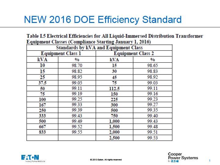
17 Efficiency Standard Comparison kva NEMA TP-1 Efficiency (%) DOE 10 CFR Part 431 Efficiency (%) All efficiency values are at 50 percent of nameplate-rated load
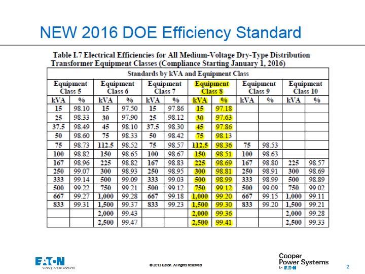
18 OE Ruling Dry Type
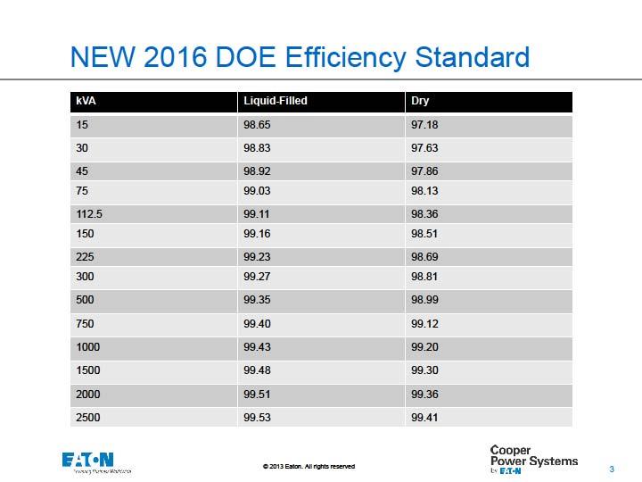
19 Liquid vs. Dry DOE 10 CFR Part 431 Efficiency (%) Comparison kva Liquid-Filled Transformers Dry Transformers kv BIL
20 fficiency Levels So, Does 0.3% Difference in Efficiency Matter? Efficiency = Rated output Rated output + Total losses Example If Performing a Loss Evaluation on 1500 kva Transformers Based on $.06/kW Hr Present Value Factor based on 6% interest over 10 years Overall conservative evaluation
21 fficiency Levels So, Does 0.3% Difference in Efficiency Matter? Efficiency = Rated output Rated output + Total losses Example If Performing a Loss Evaluation on Transformers Based on $.06/kW Hr Present Value Factor based on 6% interest over 10 years Overall conservative evaluation Example for Efficiency Difference for 1500 kva Liquid filled transformer 99.42% 50% load per DOE Total losses ~ 4375 watts (@50% load) Present value of cost of losses $16,922 Annual cost of losses 50% Load ~ 75% Load
22 fficiency Levels So, Does 0.3% Difference in Efficiency Matter? Efficiency = Rated output Rated output + Total losses Example If Performing a Loss Evaluation on Transformers Based on $.06/kW Hr Present Value Factor based on 6% interest over 10 years Overall conservative evaluation Example for Efficiency Difference for 1500 kva Liquid filled transformer 99.42% 50% load per DOE Total losses ~ 4375 watts (@50% load) Present value of cost of losses $16,922 Annual cost of losses 50% load ~ 75% load $ savings per y Dry transformer 99.12% 50% load per DOE Total Losses ~ 6659 watts (@50% load) Present value of cost of losses $25,757 Annual cost of losses 50% load ~ 75% load
23 DOE Efficiency Requirements 2010 vs. 2016
24
25
26
27 DOE Liquid Filled 2010 vs Efficiencies kva
28 016 DOE Manufacturer Implications Manufacturers will need to revise most of their active catalog numbers before to meet requirements The new efficiency levels will shift some raw material usage to amorphous cores. There may be new manufacturing challenges for many manufacturers in terms of design, manufacturing, or material procurement.
29 2016 DOE Consumer Implications Transformer weights will change Depends greatly on specific customer designs & specific product designs, but in general Increase in core/coil weight Decrease in fluid volume (core/coil displacement) Overall weight increases slightly Dimensions don t appear to change dramatically Transformer costs and prices will increase Estimates of a 5 15% price increase over the previous efficiency standard for qualifying 3 phase transformers Actual price increases are a function of what customers are paying today, movements in the materials markets, and are design specific.
30 NEC Compliance Indoors Liquid Filled Transformers Less flammable fluid filled NEC Minimum 300 C fire point In Type I or Type II non combustible building No combustible materials around transformer Liquid containment Installation to comply with all fluid listing restrictions. UL Classification FM Approval
31 UL Classification of Envirotemp FR3 Listed less flammable fluids 45 10,000 kva 3Ø transformers Substation Pad mounted 12 psig internal pressure tank withstand rating Minimum pressure relief device ratings* Either current limiting fusing or other over current protection* Other over current protection may include: Externally mounted expulsion fusing Primary breakers Only natural ester based fluid is permitted to use either CL fusing or other over current protection. *In accordance with UL Classification Marking

32 UL Classification of Envirotemp FR3
33 FM Approved transformer requirements Developed Approval Standard 3990 FM Approved transformer 1998 Restrictions based on transformer protection very similar to the UL Classification except in addition to fusing, pressure relief and tank withstand ratings: Alarm contacts on pressure relief devices for indoor installations >500 kva Rapid rise relays >2500 kva Temperature, level and pressure vacuum gages Ground fault CT on neutral Installation limitations, i.e. clearances to walls, etc.
34
35 Envirotemp FR3 fluid Benefits Fire safety characteristics Environmental characteristics Performance characteristics / enhanced life FR3 and Envirotemp are licensed trademarks of Cargill, Incorporated.
36 Fire point Mineral oil: 155 C Less flammable: min. 300 C (Required by NEC ) Envirotemp FR3 : 360 C FR3 and Envirotemp are licensed trademarks of Cargill, Incorporated.

37 Fire Safety Why Choose a Less-Flammable Fluid-Filled Transformer

38 Fire safety Envirotemp FR3 17 Years of service >450,000 installations No reported fires NFPA R Temp fluid Predecessor to FR3 35 Years of service >250,000 installations No reported fires NFPA FR3 and Envirotemp are licensed trademarks of Cargill, Incorporated

39 M Approved Transformer 1994 FM Changes Approval Restrictions Revised Less Flammable Fluid Approval Developed New Transformer Approval Standard 3990
40 ational Electric Code Less Flammable Liquid Insulated Transformers. Transformers insulated with less flammable liquids that have a fire point of not less than 300 C shall be permitted to be installed in accordance with (A) or (B).
41 FPA (B) (B) Outdoor Installations. Less flammable liquid filled transformers shall be permitted to be installed outdoors, attached to, adjacent to, or on the roof of buildings where installed in accordance with (1) or (2): (1) For Type I or Type II buildings, the installation shall comply with all listing restrictions provided for in the listing of the liquid. FPN: Installations adjacent to combustible material, fire escapes, or door or window openings may require additional safeguards such as those listed in (2) In accordance with
")
42 Making Your Medium Voltage Transformer Installations NEC Compliant 10,000(38) >10,000(38)
43 FPA (A) (A) Indoor Installations. Indoor installations shall be permitted in accordance with the following: (1) In Type I or Type II buildings, in areas where all of the following requirements are met: a. The transformer is rated 35,000 volts or less. b. No combustible materials are stored. c. A liquid confinement area is provided. d. The installation complies with all the restrictions provided for in the listing of the liquid. (2) With an automatic fire extinguishing system and a liquid confinement area, provided that the transformer is rated 35,000 volts or less. (3) In accordance with
44 Why Choose a Less-Flammable Fluid-Filled Transformer What Happened to the Indoor Liquid Filled Transformer? PCB insulated transformers were the indoor transformer of choice until the mid 1970 s. Fears developed regarding replacement fluids Environmental concerns What was the EPA going to ban next? Some transformer manufacturers leaped from the frying pan into the fire Introduced non flammable alternatives Freon Tetrachloroethylene (dry cleaning fluid) Fire Safety Concerns Operational Concerns
45 Why Choose a Less-Flammable FR3 Fluid-Filled Transformer What Did You Give Up? Higher efficiency / lower losses Greater overload capability Greater contamination resistance Higher BIL s Smaller footprint Lower temperature operation Lower noise levels Full diagnostic capabilities Longer life Dramatic cost savings
46 Transformer Ratings 55ºC Rise KNAN 65ºC Rise KNAN (+12%) Envirotran PLUS kva Ratings FR3 - Filled 75ºC Rise KNAN (+9%) 55ºC Rise KNAF (+15% or 25%) 65ºC Rise KNAF (+12%) 75ºC Rise KNAF (+9%) Fan Cooled
47 5/65/75 C Rise Base 55 C Available Ampacity 65 C Available Ampacity KVA '@ 75 C Available Ampacity With Forced Air Cooling Fans FA 55 C Available Ampacity FA 65 C Available Ampacity FA 75 C Available Ampacity

48 Why Choose a Less-Flammable Fluid-Filled Transformer Greater Overload Capability


49 Why Choose a Less-Flammable Fluid-Filled Transformer Full Diagnostic Capabilities Dry type Megger Power Factor Infra Red Scan Liquid filled Color Acidity Dielectric Breakdown Voltage Dissolved Gas Analysis Metals Analysis Inhibitor Content Interfacial Tension Infra Red Scan Power Factor Furan Analysis Water Content Specific Gravity

50 Lower sound level kva Liquid filled transformers operate at 5 6 db less than dry transformers* 3db doubles sound power to your ear *NEMA TR 1
51 ess-flammable Fluid-Filled Transformer Lower Sound Levels kva Liquid filled will be 5 6 db less than dry type 3db doubles sound power Dry Type Liquid Filled

52 Why Choose a Less-Flammable Fluid-Filled Transformer Higher Basic Impulse Level (BIL) 15kV Liquid 95kV Standard Dry 60kV Standard 35kV Liquid 200kV Standard Dry 150kV Standard 480V Liquid 30kV Standard Dry 10kV Standard


53 Why Choose a Less-Flammable Fluid-Filled Transformer Ease of Installation
54 Why Choose a Less-Flammable Fluid-Filled Transformer Smaller footprint Transformer Primary switchgear Lower Cost for lineup Overall benefit: Fit same equipment into smaller electrical rooms Reduced cost

55 Liquid vs. Dry Dimension Comparison
56 lose Coupled Liquid-filled

57 Foot print comparison Based upon published standard sizes for CPS Liquid Filled Transformers Cast Coil Dry Type Transformers
58 Higher Efficiency = Reduced Losses Efficiency Liquid kva Liquid Dry Liquid Efficiency Advantage Losses (Watts) D.O.E. Liquid Losses (Watts) D.O.E. Dry Liquid Savings % 98.83% 35.9% 3,750 $ 16,425 5,850 $ 25,623 $ 9, % 98.95% 35.2% 5,100 $ 22,338 7,875 $ 34,492 $ 12, % 99.03% 34.0% 6,400 $ 28,032 9,700 $ 42,486 $ 14, % 99.12% 34.1% 8,700 $ 38,106 13,200 $ 57,816 $ 19, % 99.18% 34.1% 10,800 $ 47,304 16,400 $ 71,832 $ 24, % 99.23% 33.8% 12,750 $ 55,845 19,250 $ 84,315 $ 28,470 Higher Efficiency = Reduced Losses Save nearly $30,000 in Energy Costs Directly tied to Losses Savings based upon D.O.E. Efficiency for 2500kVA Liquid vs Dry Per D.O.E. Ruling; Liquid Filled Transformers up to 2500kVA are approximately 35% more efficient than their Dry Type counterparts. Dry * Liquid Savings Evaluated over 5 years, based upon $.10kW Energy Rate, Load + No Load Losses
59 Higher Efficiency = Reduced Losses Cost of Losses $90,000 $85,000 $80,000 $75,000 $70,000 $65,000 $60,000 $55,000 $50,000 $45,000 $40,000 $35,000 $30,000 $25,000 $20,000 $15,000 $10,000 $5,000 $- $9,200 Savings $12,150 Savings 5 Year Cost of Losses $14,450 Savings kva $19,700 Savings $24,500 Savings For all kva Ratings; Liquid Filled Transformers = Lowest Cost of Losses $28,500 Savings D.O.E. Liquid D.O.E. Dry

60 fficiencies Considerably Less Total Losses than Cast Resin or VPI Dry Type Transformers

61 ound Levels Significantly Reduced Sound Levels and Vibration

62 perating Temperatures Cooler Operating Temperatures than Cast Resin and VPI Dry

63 EED Accreditation LEEDS Accredidation Points for Distribution Transformers Criteria DOE Transformer Energy & Atmosphere up to 19 points Material & Resources Indoor Environmental Quality Innovation & Design Description Up to 24% more efficient than equivalent non-doe design Liquid Filled vs. Dry Type % less HVAC required FR3 Envirotemp Fluid point 1 point 5 points Positive carbon footprint Total Possible Points 19 Points 1 point 1 point 5 points 26 points Obtain up to 26 LEED Points towards building installations
64 Operation at Higher Base Temperature Introduction of the 75 C rise transformer

65 Lockie Test Series (ANSI/IEEE C57.100)

66 Insulation life extension Aging of paper depends primarily on temperature and water content. Paper aged in seed oil based fluid took 5 8 times longer to reach end of life parameters than paper aged in mineral oil. FR3 and Envirotemp are licensed trademarks of Cargill, Incorporated

67 PEAK Transformer family IEEE Std C lists 75 C rise transformers PEAK transformers from Cooper Power Systems are designed to: Utilizes an advanced high temperature insulation system Thermally upgraded Kraft paper Envirotemp TM FR3 TM dielectric fluid Optimized core and coil design. Envirotemp and FR3 are licensed trademarks of Cargill, Incorporated. 67
68 PEAK Transformers Three Options 1. Increased Overload Capacity PEAK 65/75 ⁰C Average Winding Rise (AWR) Operate PEAK transformers beyond full rated base load Single phase at least 9% Three phase at least 12% Envirotemp and FR3 are licensed trademarks of Cargill, Incorporated.
69 PEAK Transformers Three Options 1. Increased Overload Capacity PEAK 65/75 ⁰C Average Winding Rise (AWR) Operate PEAK transformers beyond full rated base load Single phase at least 9% Three phase at least 12% More precisely size transformers based on periods of peak demand without accelerated reduction of insulation life Continuous overload capabilities to 75⁰ C AWR Maintains IEEE per unit life requirements at 75 ⁰C AWR Envirotemp and FR3 are licensed trademarks of Cargill, Incorporated.
70 PEAK Transformers Three Options 1. Increased Overload Capacity PEAK 65/75 ⁰C Average Winding Rise (AWR) Operate PEAK transformers beyond full rated base load Single phase at least 9% Three phase at least 12% More precisely size transformers based on periods of peak demand without accelerated reduction of insulation life Continuous overload capabilities to 75⁰ C AWR Maintains IEEE per unit life requirements at 75 ⁰C AWR 65 C AWR and 75 C AWR kva ratings on the nameplate Complies with IEEE Std C standard UL Listed Envirotemp and FR3 are licensed trademarks of Cargill, Incorporated.
71 PEAK Transformers Three Options 2. Increased Overload Capacity PEAK 55/75 ⁰C Average Winding Rise (AWR) Operate PEAK transformers beyond full rated base load Three phase at least 22% More precisely size transformers based on periods of peak demand without accelerated reduction of insulation life Continuous overload capabilities to 75⁰ C AWR Maintains IEEE per unit life requirements at 75 ⁰C AWR 55 C AWR and 75 C AWR kva ratings on the nameplate Complies with IEEE Std C standard UL Listed Envirotemp and FR3 are licensed trademarks of Cargill, Incorporated.


72 PEAK Transformers Three Options 3. Smaller, Lighter Transformers PEAK 75 ⁰C Average Winding Rise Smaller and lighter than traditional 65 C AWR transformers of the same kva rating Typically use less material and fewer gallons of dielectric fluid resulting in better value Complies with IEEE Std C standard UL Listed Envirotemp and FR3 are licensed trademarks of Cargill, Incorporated.
73 PEAK transformer PEAK Transformer kva Ratings Temp Rise (55 to 65-12%, 65 to 75-9%, 55 to 75-22%) Fans (500 to %, 2500 to %) 55ºC Rise KNAN 65ºC Rise KNAN 75ºC Rise KNAN 55ºC Rise KNAF 65ºC Rise KNAF 75ºC Rise KNAF

74 Questions? Thank You For Your Time
Envirotran COOPER POWER. Critical Load Transformer (CLT) Superior reliability and efficiency for the most demanding power applications SERIES
 Superior reliability and efficiency for the most demanding power applications SERIES") Critical Load Transformers COOPER POWER SERIES Critical Load Transformer (CLT) Superior reliability and efficiency for the most demanding power applications Photo courtesy of DuPont Fabros Technology,
Critical Load Transformers COOPER POWER SERIES Critical Load Transformer (CLT) Superior reliability and efficiency for the most demanding power applications Photo courtesy of DuPont Fabros Technology,
The Next Step In The World Of Transformers
 The Next Step In The World Of Transformers Envirotran TM Transformers Set Higher Environmental, Fire Safety and Performance Standards Envirotran TM Transformers Advance the Evolution of Electrical Distribution
B. Provide liquid-filled secondary substation transformers as indicated on drawings.
 SECTION 26 12 13 PART 1 - GENERAL 1.01 WORK INCLUDED A. Comply with the provisions of Sections 26 05 00. B. Provide liquid-filled secondary substation transformers as indicated on drawings. 1.02 RELATED
NORTHWESTERN UNIVERSITY PROJECT NAME JOB # ISSUED: 03/29/2017
 SECTION 26 1200 - MEDIUM-VOLTAGE TRANSFORMERS PART 1 - GENERAL 1.1 RELATED DOCUMENTS A. Drawings and general provisions of the Contract, including General and Supplementary Conditions and Division 01 Specification
SECTION SECONDARY UNIT SUBSTATIONS
 PART 1 - GENERAL 1.1 DESCRIPTION SECTION 26 11 16 SECONDARY UNIT SUBSTATIONS SPEC WRITER NOTE: Delete between //----// if not applicable to project. Also delete any other item or paragraph not applicable
SECTION SECONDARY UNIT SUBSTATIONS
 SECTION 26 12 16 SECONDARY UNIT SUBSTATIONS PART 1 GENERAL 1.1 SUMMARY This section describes metal-clad, indoor or outdoor, secondary unit substations with integral primary fused disconnect switches,
SECTION A. NEC Compliance: Comply with NEC as applicable to installation and construction of electrical power/distribution transformers.
 N 16461 DRY TYPE TRANSFORMERS PART 1 - GENERAL 1.01 WORK INCLUDED: A. Copper-wound transformer optimized for light loading, meeting US Department of Energy proposed Candidate Standard Level (CSL) 3 efficiency,
SECTION MEDIUM VOLTAGE TRANSFORMERS
 PART 1 - GENERAL 1.1 RELATED DOCUMENTS A. Drawings and general provisions of the Contract, including General and Supplementary Conditions, apply to this Section. 1.2 SUMMARY A. This Section includes the
MECKLENBURG COUNTY. Land Use and Environmental Service Agency Code Enforcement
 MECKLENBURG COUNTY Land Use and Environmental Service Agency Code Enforcement Draft 11/17/08 Utility transformer issues began surfacing last year with questions of enforcement responsibilities due to utility
CLARK PUBLIC UTILITIES TECHNICAL SPECIFICATIONS SINGLE-PHASE PADMOUNTED TRANSFORMERS
 CLARK PUBLIC UTILITIES TECHNICAL SPECIFICATIONS SINGLE-PHASE PADMOUNTED TRANSFORMERS Original Issue 1/84 Revised 1/91 Revised 6/02 Revised 11/05 Revised 11/09 Revised 1/12 Revised 11/12 Revised 5/14 Revised
SECTION SECONDARY UNIT SUBSTATIONS SECONDARY LESS THAN 1000 V
 SECONDARY UNIT SUBSTATIONS SECONDARY LESS THAN 1000 V PART 1 GENERAL 1.01 1.02 SCOPE The Contractor shall furnish and install the secondary unit substation(s) complete from the incoming line terminals
SECTION HIGH EFFICIENCY DISTRIBUTION TRANSFORMERS
 SECTION 26 22 13 HIGH EFFICIENCY DISTRIBUTION TRANSFORMERS PART 1 GENERAL 1.1 WORK INCLUDED A. Dry-type, low-voltage, distribution transformers meeting US Department of Energy proposed Candidate Standard
ENGINEERING SPECIFICATION
 ENGINEERING SPECIFICATION No. Page 1 CATEGORY: TRANSFORMERS DATE: 11/16/2006 Subject: TABLE OF CONTENTS PURPOSE...2 SCOPE...2 REFERENCES...2 DEFINITIONS...2 SPECIFICATION...2 General... 2 High Voltage
PRIMARY UNIT SUBSTATIONS SECONDARY 1000 V AND ABOVE SECTION SECTION
 PRIMARY UNIT SUBSTATIONS SECONDARY 1000 V AND ABOVE PART 1 GENERAL 1.01 SCOPE A. The Contractor shall furnish and install the primary unit substation(s) complete from the incoming line terminals to the
SECTION LOW-VOLTAGE TRANSFORMERS
 PART 1 GENERAL 1.1 DESCRIPTION SECTION 26 22 00 SPEC WRITER NOTE: Use this section only for NCA projects. Delete between // // if not applicable to project. Also, delete any other item or paragraph not
Important Considerations for Specifying MV Mining Switchgear Western Mining Electrical Association Edmonton, Canada June 13, 2008
 Important Considerations for Specifying MV Mining Switchgear Western Mining Electrical Association Edmonton, Canada June 13, 2008 (Above 1000V and up to 38kV for Surface Mining) Key Components of Specification:
SERIES 800 / 810 SPECIFICATION 15KV & 25KV PADMOUNTED LIQUID-INSULATED VACUUM LOAD INTERRUPTER ASSEMBLIES
 SERIES 800 / 810 SPECIFICATION 15KV & 25KV PADMOUNTED LIQUID-INSULATED VACUUM LOAD INTERRUPTER ASSEMBLIES MANUALLY OPERATED / REMOTELY OPERATED DEAD FRONT PADMOUNTED SWITCHGEAR WITH VACUUM LOAD INTERRUPTING
1 29SEP03 ALL General update with miscellaneous changes in entire document.
 REVISION RECORD SECTION 16461 Dry-Type Transformers (600 V and Less) REV DATE PAGE PARA NO. DESCRIPTION APPROVED BY 28SEP01 ALL Initial issue. 1 29SEP03 ALL General update with miscellaneous changes in
Houston First Corporation Package 1 SECTION MEDIUM VOLTAGE FUSED SWITCH INTERRUPTER
 PART 1 - GENERAL 1.1 SUMMARY SECTION 26 13 16 MEDIUM VOLTAGE FUSED SWITCH INTERRUPTER A. The scope of this section includes providing and assembling materials and equipment for the dead-front, medium voltage
SECTION to 5000 AMPERE PLUG-IN AND FEEDER BUSWAYS - SPECTRA. A. Low-Voltage Plug-in Busway to 5000 ampere, 600 VAC
 PART 1 GENERAL A. The requirements of the Contract, Division 1, and Division 16 apply to work in this Section. 1.01 SECTION INCLUDES A. Low-Voltage Plug-in Busway - 225 to 5000 ampere, 600 VAC 1.02 RELATED
CONSOLIDATED EDISON COMPANY OF NEW YORK, INC Van Dam Street Long Island City, NY ELECTRIC METER SHOP DEPARTMENT
 CONSOLIDATED EDISON COMPANY OF NEW YORK, INC. 48-05 Van Dam Street Long Island City, NY 11101 ELECTRIC METER SHOP DEPARTMENT METER ENGINEERING SPECIFICATION MES-350 REVISION 3 June 2016 EFFECTIVE DATE
Standard of Practice - Campus Electrical Distribution System
 A26.3 Standard of Practice - Campus Electrical Distribution System NOTE: Significant revisions or additions to the previous standards are highlighted in italics. GENERAL Designers shall verify that all
The complete guide to transformers and packaged substations
 LAND LOGICAL POWER The complete guide to transformers and packaged substations Contents Land Logical Power transformers An introduction to the complete range of Land Logical Power transformers and package
UNIFIED FACILITIES GUIDE SPECIFICATIONS. Use for Southeast projects only **************************************************************************
 USACE / NAVFAC / AFCESA / NASA UFGS-26 13 00.00 25 (July 2006) ------------------------------- Preparing Activity: NAVFAC Superseding Southeast UFGS-S-16345N (March 2001) Use in lieu of UFGS-26 13 00.00
S. C. Electric Cooperative s Specification for a Single-Phase, Two Bushing Overhead Distribution Transformer (Revised 10/2013)
") S. C. Electric Cooperative s Specification for a Single-Phase, Two Bushing Overhead Distribution Transformer (Revised 10/2013) 1.0 GENERAL 1.1 This specification covers the electrical and mechanical characteristics
S. C. Electric Cooperative s Specification for a Single-Phase, Two Bushing Overhead Distribution Transformer (Revised 10/2013) 1.0 GENERAL 1.1 This specification covers the electrical and mechanical characteristics
Electrical equipment floor space
 Application Paper AP083007EN Electrical equipment floor space David Bredhold, MS, Application Engineer, Louisville, KY Charles J. Nochumson, PE, National Application Engineer, Phoenix, AZ Abstract Adequate
A. This Section includes the following types of dry-type transformers rated 600 V and less, with capacities up to 1000 kva:
 SECTION 16461 - LOW-VOLTAGE TRANSFORMERS PART 1 - GENERAL 1.1 RELATED DOCUMENTS A. Drawings and general provisions of the Contract, including General and Supplementary Conditions and Division 1 Specification
TRANSFORMERS DRY TYPE, OIL FILLED, AMORPHOUS ALLOY CORE. tgood.com. Energy. Fast.
 TRANSFORMERS DRY TYPE, OIL FILLED, AMORPHOUS ALLOY CORE tgood.com Energy. Fast. TGOOD produces transformers for over 5000 prefabricated substation and switchgear units annually PRODUCT OVERVIEW Dry Type,
A&E Standards Electrical Substations & Transformers Division 26 Electrical
 A&E Standards Electrical Substations & Transformers Division 26 Electrical Version 3.0 SEP Subgroup 4.4 December 2017 PREFACE PURPOSE OF THIS DOCUMENT The intent of this document is to disseminate the
Capital Projects Group Liquid Filled Transformer Specification
 Capital Projects Group Specification Specification 26 12 13 Revision 0 Date: August 2018 Specification Specification 26 12 13 Publication Date: August 2018 COPYRIGHT 2018 Metrolinx, an Agency of the Government
ELECTRICAL INSPECTION BULLETIN (Effective )
") ELECTRICAL INSPECTION BULLETIN (Effective 2009-02-01) Rule 36-000 Customer Owned High Voltage Installations With the increase in customer own high voltage equipment there appears to be confusion over which
ELECTRICAL INSPECTION BULLETIN (Effective 2009-02-01) Rule 36-000 Customer Owned High Voltage Installations With the increase in customer own high voltage equipment there appears to be confusion over which
16300 HIGH VOLTAGE DISTRIBUTION
 16300 HIGH VOLTAGE DISTRIBUTION PART 1: GENERAL 1.01 WORK INCLUDED A. Most new loads will be served from the underground electric distribution system. This system is a primary open loop configuration served
Systems Commissioning Table of Contents
 Systems Commissioning Table of Contents C NC NA I. General II. Commissioning III. Mechanical Systems A. Testing, Adjusting, and Balancing B. Piping IV. Electrical Systems A. Load Balancing B. Electrical
PLANNING GUIDE FOR SINGLE CUSTOMER SUBSTATIONS SERVED FROM TRANSMISSION LINES
 Prepared by: NIB/EOB PLANNING GUIDE FOR SINGLE CUSTOMER SUBSTATIONS SERVED FROM TRANSMISSION LINES 05503 Department: Electric T&D Section: T&D Engineering and Technical Support Approved by: G.O. Duru (GOD)
NEC 2017 Code Changes Chapter 1 - General
 NEC 2017 Code Changes Chapter 1 - General Changes from the 2014 code are highlighted in yellow. ARTICLE 110 - Requirements for Electrical Installations Part I. General 110.1 Scope. This article covers
SERVICE ENTRANCES. OPPD S Electrical Service Designer (ESD) shall designate the Point Of Entrance.
 shall designate the Point Of Entrance.") SERVICE ENTRANCES 3.01 POINT OF ENTRANCE General Service The customer, or the customer s electrician, should provide OPPD with a site plan, load schedule, and voltage requirements when requesting service.
SERVICE ENTRANCES 3.01 POINT OF ENTRANCE General Service The customer, or the customer s electrician, should provide OPPD with a site plan, load schedule, and voltage requirements when requesting service.
DOCUMENTS PROCESSED BY THE IEEE STANDARDS BOARD
 DATE: March 10, 2006 TO: FROM: Members of IEEE Committee, Meeting @ Bill Chiu, Standards Subcommittee Chair IEEE /PES Committee SUBJECT: PE/TR Standards Activities since the October 2005 Meeting (Memphis,
Kuhlman Electric Corporation Volt Instrument Transformers
 Kuhlman Electric Corporation 5000 Volt Instrument Transformers 5000 Volt Table of Contents Description Model Page 3 ½ Window CT Single, Dual & Multi Ratio (High Accuracy Available) TD-994 3-4 3 ½ Window
North American Distribution Transformer Energy Efficiency and Distribution Transformer Energy Efficiency Task Force
 2017/EWG/EGEEC/WKSP2/006 North American Distribution Transformer Energy Efficiency and Distribution Transformer Energy Efficiency Task Force Submitted by: IEEE Workshop on Reducing Losses in Power Distribution
Acceptable values for receipt of shipments of new FR3 fluid. As-received new fluid property requirements 1.0
 Dielectric Fluids Envirotemp FR3 Fluid Electrical Apparatus R2000 DESCRIPTION Envirotemp FR3 fluid is a renewable, bio-based natural ester dielectric coolant for use in distribution and power class transformers
Unit Substation Transformer Construction Checklist (under 500 kva)
") Unit Substation Transformer Checklist (under 500 kva) Building: Location: Submittal / Approvals Submittal. The above equipment and systems integral to them are complete and ready for functional testing.
Unit Substation Transformer Checklist (under 500 kva) Building: Location: Submittal / Approvals Submittal. The above equipment and systems integral to them are complete and ready for functional testing.
600 Volt Class Transformers
 Transformers 11 11 Table of Contents - Transformers Page Full Load Current Tables... 12 General Information, Standards, Testing... 13 Selection and Application Considerations... 14 Transformer Descriptions
DISTRIBUTION TRANSFORMER SPECIFICATION #
 DISTRIBUTION TRANSFORMER SPECIFICATION #1212.03 15kV Single Phase Submersible Transformer Stainless Steel 12/2/2011 Page 1 of 8 1. SCOPE This specification covers single-phase submersible transformers
TRANSFORMERS DRY TYPE, OIL FILLED, AMORPHOUS ALLOY CORE. tgood.com. Energy. Fast.
 TRANSFORMERS DRY TYPE, OIL FILLED, AMORPHOUS ALLOY CORE tgood.com Energy. Fast. TGOOD produces transformers for over 5000 prefabricated substation and switchgear units annually PRODUCT OVERVIEW Dry Type,
Superior client serv ice. Electrical confidence. CARGILL LIMITED Transformer Oil Sampling and Analysis. June 7, 2016 File: C
 Superior client serv ice. Electrical confidence. CARGILL LIMITED 6 Transformer Oil Sampling and Analysis June 7, 6 File: C- Project Manager: George Shehata, P.Eng. info@magnaiv.com www.magnaiv.com Engineering
POWER TRANSFORMER INSTALLATION
 Project Procedure POWER TRANSFORMER INSTALLATION No.: P-6.2-8-1 07/20/2011 PAGE 1 OF 6 1.0 PURPOSE The purpose of this procedure is to ensure that power transformer installations are accomplished in compliance
UNIFIED FACILITIES GUIDE SPECIFICATIONS
 USACE / NAVFAC / AFCEC / NASA UFGS-26 12 19.10 (May 2017) -------------------------------- Preparing Activity: NAVFAC Superseding UFGS-26 12 19.10 (February 2012) UNIFIED FACILITIES GUIDE SPECIFICATIONS
ADDITIONAL CONTACT INFORMATION:
 RENEWABLE ENERGY Experience in the industry Bringing renewable power economically to the end customer requires today s most efficient technologies. As a leader in reliable transformer design and manufacturing,
January 23, Minimum Design Standards Task Force
 Minimum Transmission Design Standards for Competitive Upgrades January 23, 2015 Minimum Design Standards Task Force Revision History Date or Version Number 12/17/2014 Revision IR 1/23/2015 Revision 1 Author
MECKLENBURG COUNTY. Land Use and Environmental Service Agency Code Enforcement 11/10/10 ELECTRICAL CONSISTENCY MEETING. Code Consistency Questions
 MECKLENBURG COUNTY Land Use and Environmental Service Agency Code Enforcement 11/10/10 ELECTRICAL CONSISTENCY MEETING Code Consistency Questions 1. If a microwave oven, or refrigerator or freezer has a
A SUBSTATION CONCEPT FOR CHANGEABLE LOAD CONDITIONS
 A SUBSTATION CONCEPT FOR CHANGEABLE LOAD CONDITIONS Willy LORD SwedPower AB Sweden willy.lord@swedpower.com Lennart AHNLUND Vattenfall Eldistribution AB Sweden B. WALLBING-LÖVGREN Vattenfall Eldistribution
OPERATING PROCEDURE NO. 310
 OPERATING PROCEDURE NO. 310 Related Operating Procedures: 310A; 310B; 310C; 310D SUBJECT: Conditions of Service Issued: February 10, 2014 Revised: March 28, 2016 OBJECTIVE: To establish the rules, regulations
Arc Flash Risk in Wind Energy Systems. Guidelines for analysis, mitigation and management
 Arc Flash Risk in Wind Energy Systems Guidelines for analysis, mitigation and management Introduction Arc Flash incidents can result in significant damage to electrical distribution systems and injuries
SECTION MEDIUM VOLTAGE ELECTRICAL DISTRUBUTION (ABOVE 600 VOLTS)
") SECTION 26 10 00 MEDIUM VOLTAGE ELECTRICAL DISTRUBUTION (ABOVE 600 VOLTS) UNIVERSITY OF SOUTH ALABAMA REFERENCE INFORMATION University s Design and Construction Standards, one line diagrams, campus power
SECTION 26 10 00 MEDIUM VOLTAGE ELECTRICAL DISTRUBUTION (ABOVE 600 VOLTS) UNIVERSITY OF SOUTH ALABAMA REFERENCE INFORMATION University s Design and Construction Standards, one line diagrams, campus power
SECTION 16496A MTS MANUAL TRANSFER SWITCH (MANUAL CONTROL ONLY) Note to Spec Writer: { } Denotes EATON Feature reference number
 Note to Spec Writer: { } Denotes EATON Feature reference number") MTS MANUAL TRANSFER SWITCH (MANUAL CONTROL ONLY) Note to Spec Writer: { } Denotes EATON Feature reference number PART 1 GENERAL 01 02 03 04 SCOPE Furnish and install Manual Transfer Switches (MTS) and
MTS MANUAL TRANSFER SWITCH (MANUAL CONTROL ONLY) Note to Spec Writer: { } Denotes EATON Feature reference number PART 1 GENERAL 01 02 03 04 SCOPE Furnish and install Manual Transfer Switches (MTS) and
a) Line and load compartments must be separated by a stable barrier.
 Line and load compartments must be separated by a stable barrier.") 1.00 GENERAL 1.01 The electric utility shall furnish and connect all meters, instrument transformers, test switches, and meter control wiring necessary to complete the meter installation. 1.02 The customer
1.00 GENERAL 1.01 The electric utility shall furnish and connect all meters, instrument transformers, test switches, and meter control wiring necessary to complete the meter installation. 1.02 The customer
ATTACHMENT A - TECHNICAL SPECIFICATIONS 1.1 GENERAL REQUIREMENTS
 ATTACHMENT A - TECHNICAL SPECIFICATIONS 1.1 GENERAL REQUIREMENTS 1.1.1 A ground-mounted, single-axis tracking photovoltaic (PV) power plant is to be constructed as specified herein. The Vendor shall be
Northern Powergrid Appendix B for ENA Engineering Recommendation G81 Part 4: Design and Planning
 Version:- 2.0 Date of Issue:- Sept 2013 Page 1 of 10 Northern Powergrid Appendix B for ENA Engineering Recommendation G81 Part 4: Design and Planning Framework for design and planning, materials specification,
Equipment Specifications Low Voltage. Active Harmonic Filter
 Equipment Specifications Low Voltage Active Harmonic Filter 1.0 General Description This section contains the design standards, general equipment type and configuration, components, product description,
MIRUS International Inc.
 MIRUS International Inc. INSTALLATION, OPERATION AND MAINTENANCE GUIDE AUTOTRANSFORMER AND UNIVERSAL HARMONIC FILTER IMPORTANT SAFETY INSTRUCTION SAVE THESE INSTRUCTIONS - This manual contains important
SECTION REQUIREMENTS FOR ELECTRICAL INSTALLATIONS
 PART 1 - GENERAL 1.1 DESCRIPTION SECTION 26 05 11 REQUIREMENTS FOR ELECTRICAL INSTALLATIONS SPEC WRITER NOTE: Delete between // // if not applicable to project. Also delete any other item or paragraph
Assessing the Health of a Facility s Electrical Power Distribution System
 Assessing the Health of a Facility s Electrical Power Distribution System 1910DB1103 / September, 2011 by S. Frank Waterer, Electrical Engineering, Fellow Schneider Electric USA, Inc. Make the most of
SECTION FIELD PANELS
 Stanford University Facilities Design Guidelines SECTION 25 14 23 FIELD PANELS PART 1 - GENERAL 1.1 SUMMARY A. This section includes control panel and enclosure requirements for building control systems.
MANUFACTURING TECHNICAL INSTRUCTIONS SAFETY Subject: DESIGN, MAINTENANCE AND INSPECTION OF SECONDARY ELECTRICAL DISTRIBUTION SYSTEMS
 DAIMLERCHRYSLER MANUFACTURING TECHNICAL INSTRUCTIONS SAFETY Subject: DESIGN, MAINTENANCE AND INSPECTION OF SECONDARY ELECTRICAL DISTRIBUTION SYSTEMS ISSUE DATE: 5/1/90 EFFECTIVE DATE: 2/4/92 REVIEW DATE:
Cargill Industrial Specialties
 Cargill Industrial Specialties A GLOBAL PARTNER YOU CAN COUNT ON. As an internationally recognized ester fluids expert and global supply chain manager, Cargill Industrial Specialties supplies dielectric
CFFWA-20-1-U Chilled/Hot Water Universal Mount Fan Coil 2-Pipe Heat / Cool Fan Coil 60,000 BTUH
 CFFWA-20-1-U Chilled/Hot Water Universal Mount Fan Coil 2-Pipe Heat / Cool Fan Coil 60,000 BTUH Rev. 1.3 HVAC Guide Specifications Chilled and Hot Water Universal Mount Fan Coil 2-Pipe Nominal Size: 60,000
UNIFIED FACILITIES GUIDE SPECIFICATIONS
 USACE / NAVFAC / AFCEC / NASA UFGS-33 77 19.00 40 (August 2016) --------------------------------- Preparing Activity: NASA Superseding UFGS-33 77 19.00 40 (August 2013) UNIFIED FACILITIES GUIDE SPECIFICATIONS
ANSI/IEEE Standard C57.12"Standard Guide for Loading Mineral Oil Insulated Transformers"
 References: ANSI/IEEE Standard C57.12"Standard Guide for Loading Mineral Oil Insulated Transformers" IEEE Project P1276 "IEEE Guide for the Application of High Temperature Insulation Materials in Liquid
Power Zone Center. Your solution for power distribution and control systems
 Power Zone Center Your solution for power distribution and control systems The Strength of One Powerful When you need to install a new power distribution center in your facility, you need it done in fastest
MREC March, 2005 Powering the Dairy Industry
 Mark A. Cook Manager Licensed Designer of Engineering Systems Certified Commercial and UDC Electrical Inspector Certified Master Electrician Public Service Commission of Wisconsin mark.cook@starband.net
High Voltage Pad-mount Transformer Technical Discussion
 High Voltage Pad-mount Transformer Technical Discussion Jordan Ringash, P.Eng, Manitoba Hydro, Underground Standards Engineer Matthew de Monye, P.Eng, Manitoba Hydro International, Project Engineer With
Seismic Considerations of Circuit Breakers
 Seismic Considerations of Circuit Breakers Willie Freeman, IEEE 693 Working Group ABB Inc, Mt. Pleasant PA, USA IEEE Tutorial - 2008 Abstract: The tutorial covers the seismic qualification of high voltage
UNDERGROUND SERVICES SECONDARY
 Reference UNDERGROUND SERVICES SECONDARY Underground services secondary... U- 1 General requirements for underground service... U- 2 Name of parts for underground service... U- 3 Conduit layouts... U-
TOGA Electrical Insulating Fluid Analysis. Improving performance and protecting assets.
 TOGA Electrical Insulating Fluid Analysis Improving performance and protecting assets. It happens all the time - transformers fail unexpectedly, and there are often no external visual clues on what caused
DuPont TM. ReliatraN TM SOLID INSULATION DISTRIBUTION TRANSFORMER
 DuPont TM ReliatraN TM SOLID INSULATION DISTRIBUTION TRANSFORMER DuPont TM ReliatraN TM Single phase submersible solid insulation distribution transformer (SIDT) made with DuPont TM Nomex DuPont TM ReliatraN
envirotempfluids.com Envirotemp FR3 fluid. Trusted worldwide a million times over.
 Envirotemp FR3 fluid. Trusted worldwide a million times over. With over one million installations across six continents and validated in over 250 tests, Cargill s Envirotemp FR3 natural ester fluid is
UFGS (August 2010) UNIFIED FACILITIES GUIDE SPECIFICATIONS
 UNIFIED FACILITIES GUIDE SPECIFICATIONS") USACE / NAVFAC / AFCEC / NASA UFGS-26 35 33.00 40 (August 2013) --------------------------------- Preparing Activity: NASA Superseding UFGS-26 35 33.00 40 (August 2010) UNIFIED FACILITIES GUIDE SPECIFICATIONS
USACE / NAVFAC / AFCEC / NASA UFGS-26 35 33.00 40 (August 2013) --------------------------------- Preparing Activity: NASA Superseding UFGS-26 35 33.00 40 (August 2010) UNIFIED FACILITIES GUIDE SPECIFICATIONS
DIVISION MEDIUM VOLTAGE VAULT DESIGN Contents MEDIUM VOLTAGE VAULT DESIGN... 2 DIVISION LIST OF FIGURES...
 DIVISION 13 00 60 - MEDIUM VOLTAGE VAULT DESIGN Contents 13 00 60 - MEDIUM VOLTAGE VAULT DESIGN... 2 DIVISION 13 00 60 LIST OF FIGURES... 6 13 00 60 - MEDIUM VOLTAGE VAULT DESIGN 1. General Requirements
Minimum Transmission Design Standards f or Competitive Upgrades Rev 2
 Minimum Transmission Design Standards f or Competitive Upgrades Rev 2 December, 2016 Minimum Design Standards Task Force Revision History Date or Version Number 12/17/2014 Revision IR Author Change Description
PID275 Feasibility Study Report 9.33 MW Distribution Inter-Connection Valentine Substation
 PID275 Feasibility Study Report 9.33 MW Distribution Inter-Connection Valentine Substation Prepared by: Entergy Services, Inc. T & D Planning 639 Loyola Avenue L-ENT-17A New Orleans, LA 70113 Rev Issue
UNIFIED FACILITIES GUIDE SPECIFICATIONS
 USACE / NAVFAC / AFCEC / NASA UFGS-26 11 16 (February 2010) Change 1-08/17 ----------------------------- Preparing Activity: NAVFAC Superseding UFGS-26 11 16 (April 2007) UNIFIED FACILITIES GUIDE SPECIFICATIONS
MHWW-09-H-1 Chilled/Hot Water Hi-Wall Fan Coil. Heat / Cool Fan Coil 9,000 BTUH. Rev. 1.3
 MHWW-09-H-1 Chilled/Hot Water Hi-Wall Fan Coil Heat / Cool Fan Coil 9,000 BTUH Rev. 1.3 HVAC Guide Specifications Chilled and Hot Water Hi-Wall Fan Coil 2-Pipe Nominal Size: 9,000 BTUH Multiaqua Model
MHWW-18-H-1 Chilled/Hot Water Hi-Wall Fan Coil. Heat / Cool Fan Coil 18,000 BTUH. Rev. 1.3
 MHWW-18-H-1 Chilled/Hot Water Hi-Wall Fan Coil Heat / Cool Fan Coil 18,000 BTUH Rev. 1.3 HVAC Guide Specifications Chilled and Hot Water Hi-Wall Fan Coil 2-Pipe Nominal Size: 18,000 BTUH Multiaqua Model
MHWW-12-H-1 Chilled/Hot Water Hi-Wall Fan Coil. Heat / Cool Fan Coil 12,000 BTUH. Rev. 1.3
 MHWW-12-H-1 Chilled/Hot Water Hi-Wall Fan Coil Heat / Cool Fan Coil 12,000 BTUH Rev. 1.3 HVAC Guide Specifications Chilled and Hot Water Hi-Wall Fan Coil 2-Pipe Nominal Size: 12,000 BTUH Multiaqua Model
DIVISION MEDIUM VOLTAGE VAULT DESIGN Contents
 DIVISION 13 00 60 - MEDIUM VOLTAGE VAULT DESIGN Contents 13 00 60 - MEDIUM VOLTAGE VAULT DESIGN... 2 DIVISION 13 00 60 LIST OF FIGURES... 6 Page 1 of 6 13 00 60 - MEDIUM VOLTAGE VAULT DESIGN 1. General
Instruction Manual. Ventilated Dry-Type Transformers. 600 Volts & Below
 Instruction Manual Ventilated Dry-Type Transformers 600 Volts & Below Instructions for the Safe Handling, Installation, Operation and Maintenance of Ventilated Dry-Type Transformers Table of Contents Paragraph
SECTION HVAC WATER TREATMENT
 PART 1 - GENERAL 1.1 DESCRIPTION SECTION 23 25 00 SPEC WRITER NOTES: 1. Use this section only for NCA projects. 2. Delete between //-----// if not applicable to project. Also delete any other item or paragraph
MECKLENBURG COUNTY. Land Use and Environmental Service Agency Code Enforcement 7/14/10 ELECTRICAL CONSISTENCY MEETING. Code Consistency Questions
 MECKLENBURG COUNTY Land Use and Environmental Service Agency Code Enforcement 7/14/10 ELECTRICAL CONSISTENCY MEETING Code Consistency Questions 1. We were turned down for an underground installation of
Title: YALE OFFICE OF FACILITIES PROCEDURE MANUAL Chapter: 01 - Yale Design Standard Division: Electrical Standards
 Change History Date Description of Change Pages / Sections Modified Change Approver Initials 6/15/16 Updated division section from 16124 to 2605 - mgl44 13, removed references to other section 10/17/14
UNIFIED FACILITIES GUIDE SPECIFICATIONS
 USACE / NAVFAC / AFCEC / NASA UFGS-26 13 01 (August 2013) --------------------------- Preparing Activity: NAVFAC NEW UNIFIED FACILITIES GUIDE SPECIFICATIONS References are in agreement with UMRL dated
Installation Instructions
 Installation Instructions AquaSnap 010-055 Chilled Water Storage Tank 50/60 Hz Part No: -900---001; -900---009; -900---010 CONTENTS INTRODUCTION.................................. 1 SAFETY CONSIDERATIONS......................
UNITED COOPERATIVE SERVICES. SPECIFICATIONS FOR SELF-CONTAINED METER INSTALLATIONS August 2014
 UNITED COOPERATIVE SERVICES SPECIFICATIONS FOR SELF-CONTAINED METER INSTALLATIONS August 2014 A member may obtain a new, single phase service from the Cooperative by providing or purchasing a meter loop.
Online Condition Monitoring of Transformer
 Online Condition Monitoring of Transformer ---------------------------------------------------- Heart of any power system An essential Part of a Cost efficient maintenance Program. It is well known that
SECTION ENCLOSED BUS ASSEMBLIES
 SECTION 262500 ENCLOSED BUS ASSEMBLIES PART 1 - GENERAL 1.1 RELATED DOCUMENTS A. Drawings and general provisions of the Contract, including General and Supplementary Conditions and Division 01 Specification
Enhance Power Equipment Reliability with Predictive Maintenance Technologies
 Enhance Power Equipment Reliability with Predictive Maintenance Technologies November 2012/1910DB1208 by S. Frank Waterer, Electrical Engineerinig, Fellow Schneider Electric USA, Inc. Make the most of
MF Product Specifications
 Product Specifications MODULAR ELECTRIC FURNACE 2, 3, 4, and 5 TONS FEATURES Modular Blower Cabinet, Air Conditioning or Heat Pump ready Upflow, horizontal right or left applications Downflow requires
SECTION HEAT TRACING FOR PLUMBING PIPING
 SECTION 22 05 33 HEAT TRACING FOR PLUMBING PIPING PART 1 - GENERAL 1.1 DESCRIPTION SPEC WRITER NOTES: 1. Delete between //----// if not applicable to project. Also delete any other item or paragraph not
A. Provide a complete Distribution Panelboard system as indicated on the drawings, and as specified herein.
 16470 PANELBOARDS ************************************************************************************************************* SPECIFIER: CSI MasterFormat 2004 number: 26 24 16 An optional keynote to
ELECTRICAL BULLETIN
 PO Box 697 Halifax, Nova Scotia B3J 2T8 Labour and Advanced Education ELECTRICAL BULLETIN 2012-01 From: David MacLeod,C.E.I.,P.Eng. Pg 1 of 8 Provincial Chief Electrical Inspector Date : March 1, 2012
SUMMARY OF PROPOSED CHANGES
 EXHIBIT D Part 1 General 1.04 (d) Backflow Prevention Assembly: More precise definition. To prevent a backflowwash of water from private system into the public drinking into the general water system. 1.21