ATTACHMENT C Design Analysis for Erosion Protection Cover for Piñon Ridge Tailing Cells
|
|
|
- Simon Lawson
- 6 years ago
- Views:
Transcription
1 ATTACHMENT C Design Analysis for Erosion Protection Cover for Piñon Ridge Tailing Cells TAILING CELL CLOSURE DESIGN REPORT ENERGY FUELS RESOURCE CORPORATION PIÑON RIDGE PROJECT
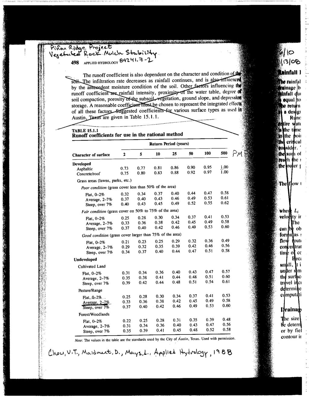
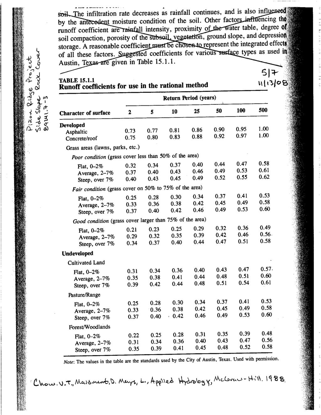
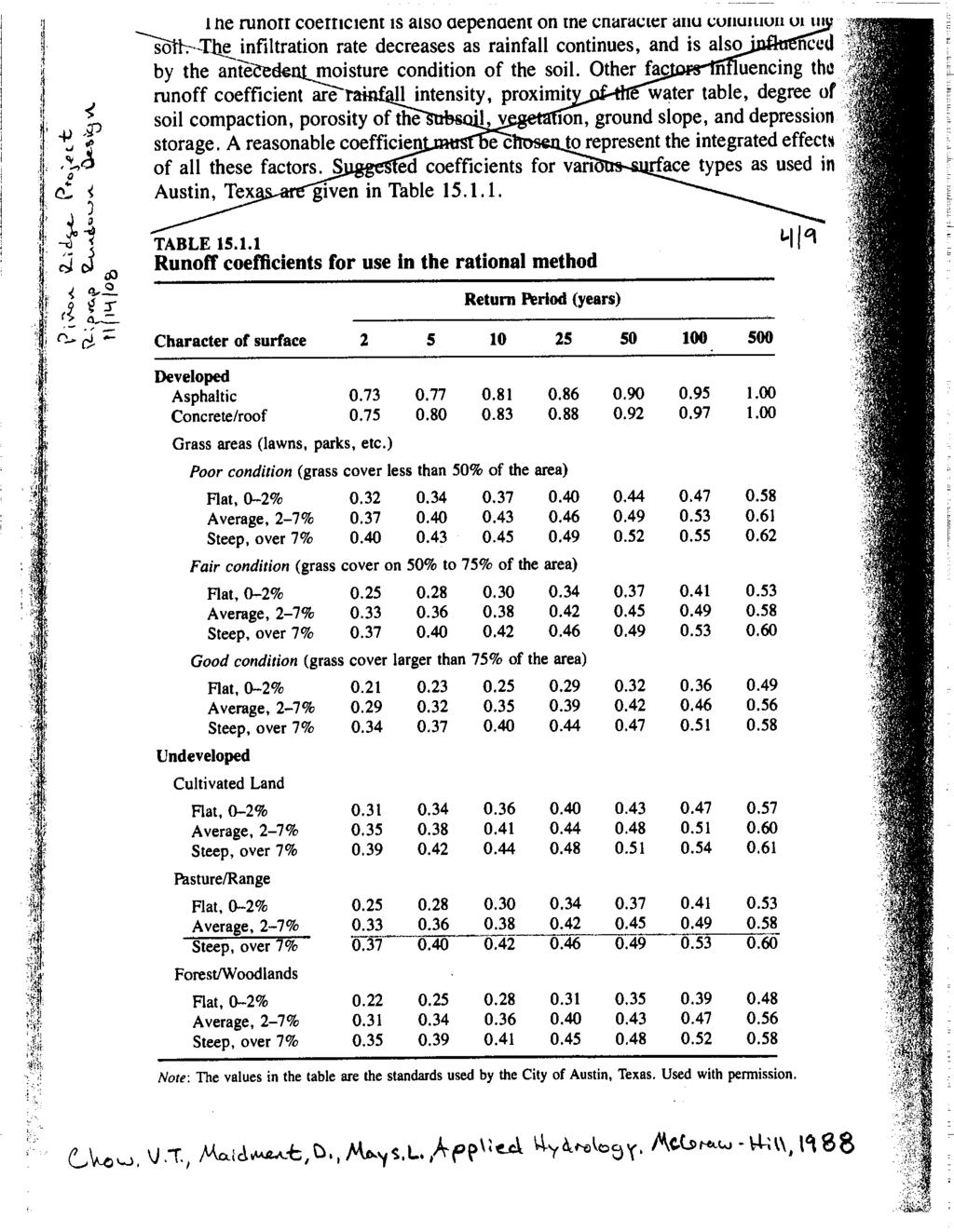
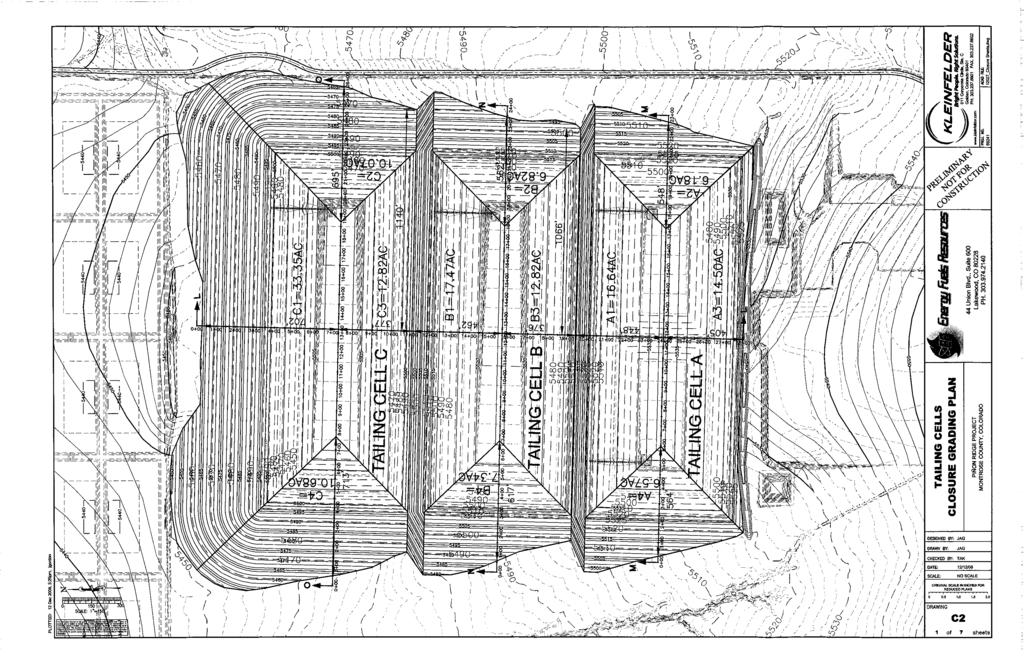
2 Summary The primary purpose of the tailing cell erosion cover is to protect the tailing cell cover from erosion by runoff of precipitation and by wind. Of these two, runoff presents the greater hazard. As suggested in NUREG-1620 (USNRC, 2003), the tailing cell erosion cover is designed to withstand the Probable Maximum Flood (PMF) resulting from the Probable Maximum Precipitation (PMP). The methods used for determining the PMF, top and side slope cover design, and tailing cell toe protection follow guidelines suggested by the Nuclear Regulatory Commission in NUREG-1623, Design of Erosion Protection for Long-Term Stabilization (USNRC, 2002). The following discusses the basic approach, methodology, and key parameters used in the tailing cell cover erosion design. Full calculations (Kleinfelder document DEN8R197, December 9, 2008) are included following this summary. PMP and PMF Calculations The PMP was calculated using procedures outlined in Hydrometeorological Report No. 49 (HMR 49). Each tailing cell has an approximate footprint of 0.05 square miles so no areal reduction was applied to the rainfall depth calculation. A 6-hr Local Storm depth was calculated and applied to the appropriate HMR-49 storm distribution. The maximum 1-hour rainfall depth increment for the 6-hr Local Storm distribution was determined to be 7.6 inches. NOAA Atlas 2 Volume III (Miller et al., 1973) was followed to create an intensityduration curve for tailing cell drainages shown below in Table 1. Table 1 Intensity-Duration Values for Piñon Ridge Mill Site, Montrose County, Colorado Duration (min) 1 = Intensity (in/hr) = Miller et al, 1973 The times of concentration for the tailing cell drainages were calculated using Kirpich s method, Equation (1) (Barfield et al., 1981) T c L S (1) where T c is time of concentration in minutes, L is the maximum length of flow in feet, and S is the slope of the drainage in feet/foot. 2
3 The Rational Method (Barfield et al., 1981) was used to calculate the PMF for each drainage on the tailing cell configuration. Based on the magnitude of the design event and anticipated soil and vegetation conditions, a conservative runoff coefficient value of 0.8 was chosen. A flow concentration factor of 3.0 was selected for top and side slope cover designs to account for concentrated sheet flow conditions. The Rational Method is given below in Equation (2) Q FCiA (2) where Q is the maximum discharge in cubic feet per second (cfs), F is a flow concentration factor (only used for sheet flow conditions), C is a runoff coefficient, i is rainfall intensity in inches/hour, and A is the drainage area in acres. A unit discharge rate was used in designing the top and side covers while a conventional peak discharge for a given area was calculated for the riprap channel rundowns. Top and Side Slope Covers PMF unit discharges were used in the Safety Factor method (Barfield et al., 1981) to determine an appropriate rock size for the tailing cell top cover. The Maximum Permissible Velocity (MPV) method (Chow, 1959) was used to design a stable vegetated soil/rock mulch cover. PMF unit discharges were also used in the Stephenson Method to design a rock cover for the steeper tailing cell outslopes. The Safety Factors method was used for slopes less than 10% while the Stephenson Method was used for slopes of 10% or greater (NUREG-1623, 2002). The Safety Factors method is given in Equation (3) cos( ) tan( ) SFb sin( ) b tan( ) 21 b ( SG 1) D c 21dS D 50 ( SG 1) 50 (3) where SF b is the safety factor, θ is the slope angle in degrees, φ is the materials friction angle in degrees, η b is a stability parameter, τ is applied tractive force in psf, τ c is the critical tractive force in psf, γ is the specific weight of water in pcf, SG is the specific gravity of the cover material, d is flow depth in feet, S is longitudinal slope in feet/foot, and D 50 is the representative material size in feet. 3
4 A safety factor of 1.0 indicates the moment of incipient motion for a representative cover particle; therefore, a safety factor of 1.1 was used in the design to maintain stable conditions (i.e. no particle movement). The MPV method was used to design a stable vegetated top cover with an approximate slope of 2%. Assuming a cover composed of a grass mixture, a 2% average slope, and easily erodible soils an MPV of 4.0 fps was chosen from Table 7-6 in Chow s Open Channel Hydraulics (Chow, 1959). PMF unit discharges were used with Manning s equation to determine maximum expected flow depths and velocities. In compliance with recommendations outlined in NUREG-1623, a correction factor was applied to the MPV to accurately represent sheet flow conditions and reduced it to 2.0 fps. A low vegetal retardance factor was chosen to represent a fair stand with average grass lengths of two to six inches on the tailing cell covers. A Manning s n value was subsequently computed using Chow s experimental curves. An iterative approach was taken until a maximum expected PMF velocity was determined. If the expected MPV was less than the permissible MPV of 2.0 fps, the design was considered acceptable. The Stephenson Method was used to design a rock cover for the tailing cell side slopes. The Stephenson Method is given in Equation (4) D 50 Cg 1 2 q tan( ) 6 n 1 n SG 1 cos( ) tan( ) tan( ) p p (4) 5 3 where D 50 is the representative particle size in feet, q is maximum unit discharge in cfs/ft, θ is the slope angle in degrees, φ is the material friction angle in degrees, n p is the cover material porosity, C is the Stephenson coefficient, g is the acceleration of gravity in ft/s 2, and SG is the specific gravity of the cover material. Drainage Features The overall erosion cover was designed to minimize concentrating flow in channels that require large sizes of riprap. This was done to minimize costs, future maintenance efforts, and to reduce areas of high volume, high velocity flows. However, runoff will unavoidably be concentrated in the grading intersections between Tailing Cells A and B and Cells B and C. Runoff collected in these areas will be directed to riprap lined channels flowing down the groin area between the tailing cells. The channels are designed to route the PMF away from the tailing cells, eventually discharging into natural drainages at the site. Riprap for the rundown channels was designed using experimental curves developed by Bathurst (1979) published in the Surface Mining Water Diversion 4
5 Design Manual (1982). It is important to note that the areas receiving concentrated flow are constructed over natural fill embankments and not tailings. Erosion protection at the toe of the tailing cells was designed using the Abt et al. (1998) method, Equation (5) D C f q S 0.43 (5) d where D 50 is the representative particle size in feet, S is the longitudinal slope in feet/foot, C f is the flow concentration factor, and q d is the maximum unit discharge in cfs/ft. All rock material used for the erosion cover will meet the criteria for durability outlined in NUREG-1623, Appendix D. The tailing cell configuration is generally located on northward sloping terrain with several natural drainages (arroyos) directing flow away from the centerline of the cells toward the northwest and northeast ends of the site. The natural drainage network and overall slope of the site help to direct runoff away from the tailing cells, protecting them from long-term erosion. A riprap-lined diversion berm, designed for the PMF, will be constructed south of Tailing Cell A to redirect runoff from the tailing cell area to natural drainages that will eventually flow offsite. The design of the diversion berm will be consistent with the methods used for the riprap rundown channels. 5
6 References Abt, S.R., Johnson, T.L., Thornton, C.I., and Trabant, S.C., 1998, Riprap Sizing at the Toe of Embankment Slopes. J. of Hydr. Engr., ASCE, Barfield, B. J., R. C. Warner, and C. T. Hahn, 1981, Applied Hydrology and Sedimentology for Disturbed Areas. Oklahoma Technical Press, Stillwater, Oklahoma, Bathurst, J.C., R.M. Li, D.B. Simons, 1979, Hydraulics of Mountain Rivers. Civil Engineering Department, Colorado State University, CER78-79JCB-RML- DBS55, Chow, V.T., 1959, Open Channel Hydraulics. McGraw-Hill Book Company, Inc., New York, NY, Hansen, E., Schwartz, F., Riedel, J., 1984, Probable Maximum Precipitation Estimates, Colorado River and Great Basin Drainages. Hydrometeorological Report No. 49, Miller, J.F., R.H. Frederick, R.J. Tracey, 1973, "Precipitation-Frequency Atlas of the Western United States," NOAA Atlas 2 Volume III--Colorado, National Oceanic and Atmospheric Administration, National Weather Service, U.S. Department of Commerce, Silver Spring, MD, U.S. Nuclear Regulatory Commission (USNRC), 2002, Design of Erosion Protection for Long-Term Stabilization. NUREG-1623, U.S. Nuclear Regulatory Commission (USNRC), 2003, Standard Review Plan for the Review of a Reclamation Plan for Mill Tailing Sites Under Title II of the Uranium Mill Tailings Radiation Control Act of NUREG-1620, Rev. 1, U.S. Dept. of the Interior: Office of Surface Mining, 1982, Surface Mining Water Diversion Design Manual, U.S. Government Printing Office, Washington D.C.,
7
8
9
10
11
12
13
14
15
16
17
18
19
20
21
22
23
24
25
26
27
28
29
30
31
32
33
34
35
36
37
38
39
40
41
42
43
44
45
46
47
48
49
50
51
52
53
54
55
56
57
58
59
60
61
62
63
64
65
66
67
68
69
70
71
72
73
74
75
76

77
78
79
80
81
82
83
84
85
Prepared for Urban Drainage and Flood Control District
 BERM FAILURE TECHNICAL ANALYSES SOUTH PLATTE GRAVEL PIT EVALUATION CRITERIA Prepared for Urban Drainage and Flood Control District Wright Water Engineers, Inc. January 2013 121-030.000 TABLE OF CONTENTS
Chapter 6. Hydrology. 6.0 Introduction. 6.1 Design Rainfall
 6.0 Introduction This chapter summarizes methodology for determining rainfall and runoff information for the design of stormwater management facilities in the City. The methodology is based on the procedures
HYDROLOGIC MODELING CONSISTENCY AND SENSITIVITY TO WATERSHED SIZE
 HYDROLOGIC MODELING CONSISTENCY AND SENSITIVITY TO WATERSHED SIZE by James C.Y. Guo. Professor, Civil Engineering, U. Of Colorado at Denver, James.Guo@cudenver.edu.. And Eric Hsu, Project Engineer, Parson
Overview of NRCS (SCS) TR-20 By Dr. R.M. Ragan
 TR-20 By Dr. R.M. Ragan") Overview of NRCS (SCS) TR-20 By Dr. R.M. Ragan TR-20 is a computer program for the simulation of runoff occurring from a single storm event. The program develops flood hydrographs from runoff and routes
Overview of NRCS (SCS) TR-20 By Dr. R.M. Ragan TR-20 is a computer program for the simulation of runoff occurring from a single storm event. The program develops flood hydrographs from runoff and routes
Engineering Hydrology Class 3
 Engineering Hydrology Class 3 Topics and Goals: I.Develop s (estimate precipitation) II.Develop simple constant intensity design storm III.Develop SCS design storm Ocean s Why do we want to derive the?
DIVISION 5 STORM DRAINAGE CRITERIA
 DIVISION 5 STORM DRAINAGE CRITERIA Section 5.01 GENERAL The following storm drainage design criteria shall apply to all storm drainage designs in the City. Additional design criteria are specified in the
Appendix B. Storm Drain System Data
 MENIFEE VALLEY CAMPUS MASTER PLAN FINAL EIR MT. SAN JACINTO COMMUNITY COLLEGE DISTRICT Appendix Appendix B. Storm Drain System Data June 2017 MENIFEE VALLEY CAMPUS MASTER PLAN FINAL EIR MT. SAN JACINTO
Ponds. Pond A water impoundment made by excavating a pit, or constructing a dam or an embankment.
 POND SITE SELECTION AND CONSTRUCTION Uses, Planning, & Design David Krietemeyer Area Engineer USDA-NRCS June 20, 2008 Uses Considerations for Location of Commonly Used Terms Pond A water impoundment made
Culvert Sizing procedures for the 100-Year Peak Flow
 CULVERT SIZING PROCEDURES FOR THE 100-YEAR PEAK FLOW 343 APPENDIX A: Culvert Sizing procedures for the 100-Year Peak Flow A. INTRODUCTION Several methods have been developed for estimating the peak flood
Inflow Design Flood Control System Plan
 Inflow Design Flood Control System Plan For Compliance with the Coal Combustion Residuals Rule (40 CFR Part 257) Valmont Station - CCR Surface Impoundments Public Service Company of Colorado Denver, Colorado
Standards for Soil Erosion and Sediment Control in New Jersey May 2012 STANDARD FOR GRASSED WATERWAYS. Definition. Purpose
 STANDARD FOR GRASSED WATERWAYS Definition A natural or constructed watercourse shaped or graded in earth materials and stabilized with suitable vegetation for the safe conveyance of runoff water. Purpose
Chapter 6 Hydrology TABLE OF CONTENTS CHAPTER 6 - HYDROLOGY
 Chapter 6 Hydrology TABLE OF CONTENTS CHAPTER 6 - HYDROLOGY... 6-1 6.1 Introduction... 6-1 6.1.1 Objective... 6-1 6.1.2 Definition... 6-1 6.1.3 Factors Affecting Floods... 6-1 6.1.4 Sources of Information...
North Carolina Sedimentation Control Law
 1 North Carolina Sedimentation Control Law North Carolina Sediment Control Law 1 North Carolina Sedimentation Control Law The purpose of this section is to highlight the portions of the North Carolina
APPENDIX G HYDRAULIC GRADE LINE
 Storm Drainage 13-G-1 APPENDIX G HYDRAULIC GRADE LINE 1.0 Introduction The hydraulic grade line is used to aid the designer in determining the acceptability of a proposed or evaluation of an existing storm
Applying landforming to reclamation: A case study in Central Appalachia
 Applying landforming to reclamation: A case study in Central Appalachia Leslie Hopkinson, John Quaranta April 12, 2017 Department of Civil and Environmental Engineering West Virginia University WEST VIRGINIA
Table of Contents. Overview... 1
 Chapter 3 Chapter 3 Table of Contents Overview... 1 Rainfall... 2 3-2-1 Rainfall Depths and Intensities... 2 3-2-2 Design Storm Distribution for Colorado Urban Hydrograph Procedure (CUHP)... 5 3-2-3 Temporal
APPENDIX IV. APPROVED METHODS FOR QUANTIFYING HYDROLOGIC CONDITIONS OF CONCERN (NORTH ORANGE COUNTY)
") APPENDIX IV. APPROVED METHODS FOR QUANTIFYING HYDROLOGIC CONDITIONS OF CONCERN (NORTH ORANGE COUNTY) Hydromodification design criteria for the North Orange County permit area are based on the 2- yr, 24-hr
APPENDIX IV. APPROVED METHODS FOR QUANTIFYING HYDROLOGIC CONDITIONS OF CONCERN (NORTH ORANGE COUNTY) Hydromodification design criteria for the North Orange County permit area are based on the 2- yr, 24-hr
CEE3430 Engineering Hydrology
 CEE3430 Engineering Hydrology Practice Exam (There are multiple practice questions here A 110 min test will likely not have more than four questions) 1. Water Balance Write the water balance as Δ Where
Constructed Wetland Channel T-9
 Description A constructed wetland channel is a conveyance BMP that is built, in part, to enhance stormwater quality. Constructed wetland channels use dense vegetation to slow down runoff and allow time
TECHNICAL BULLETIN. Synthetic Turf Athletic Field Drainage Design Assistance
 TECHNICAL BULLETIN Synthetic Turf Athletic Field Drainage Design Assistance The SportsEdge HQ geocomposite strip drain products are engineered specifically for use in synthetic turf athletic field base
Section 500 Rainfall Table of Contents
 Boulder Storm Drainage Criteria Manual Section 5 Rainfall Table of Contents 51 INTRODCTION... 5-1 52 INTENSITY-DRATION CRES FOR RATIONAL METHOD... 5-1 53 COLORADO RBAN HYDROGRAPH PROCEDRE RAINFALL HYETOGRAPHS...
SAN GORGONIO PASS CAMPUS - PHASE I
 SAN GORGONIO PASS CAMPUS - PHASE I Banning, CA DRAINAGE STUDY June 16, 2010 Reference 106-195 PREPARED BY: Encompass Associates, Inc. 5699 Cousins Place Rancho Cucamonga, CA 91737 909-684-0093 Fax-909-586-6979
ENVIRONMENTAL ENGINEERING LAND SURVEYING
 ENVIRONMENTAL ENGINEERING LAND SURVEYING Inflow Design Flood Control System Plan Bottom Ash Pond Sherburne County Generating Plant Introduction This report presents documentation and certification of the
Updated Rainfall Coefficients for Texas The EBDLKUP-NEW.XLS Tool
 442 Updated Rainfall Coefficients for Texas The EBDLKUP-NEW.XLS Tool Cristal C. Tay 1, Caroline M. Neale 1, George R. Herrmann 2, and Theodore G. Cleveland 3 1 Graduate Research Assistant, 2 Postdoctoral
Pre-Treatment Bioretention Cells Bioswales IOWA STORMWATER MANAGEMENT MANUAL DECEMBER 16, 2015
 Pre-Treatment Bioretention Cells Bioswales IOWA STORMWATER MANAGEMENT MANUAL DECEMBER 16, 2015 Urban Runoff Background How we got here What Problem?? Provenance of the Problem Unified Sizing Criteria What
Standards for Soil Erosion and Sediment Control in New Jersey May 2012 STANDARD FOR SLOPE PROTECTION STRUCTURES. Definition
 STANDARD FOR SLOPE PROTECTION STRUCTURES Definition Structures to safely conduct surface runoff from the top of a slope to the bottom of the slope. Purpose The purpose of this practice is to convey storm
Project Drainage Report
 Design Manual Chapter 2 - Stormwater 2A - General Information 2A-4 Project Drainage Report A. Purpose The purpose of the project drainage report is to identify and propose specific solutions to stormwater
Learning objectives. Upon successful completion of this lecture, the participants will be able to:
 Solomon Seyoum Learning objectives Upon successful completion of this lecture, the participants will be able to: Describe and perform the required step for designing sewer system networks Outline Design
Summary of Detention Pond Calculation Canyon Estates American Canyon, California
 July 15, 2015 Bellecci & Associates, Inc Summary of Detention Pond Calculation Canyon Estates American Canyon, California 1. Methodology: Method: Unit Hydrograph Software: Bentley Pond Pack Version 8i
UNIT HYDROGRAPH AND EFFECTIVE RAINFALL S INFLUENCE OVER THE STORM RUNOFF HYDROGRAPH
 UNIT HYDROGRAPH AND EFFECTIVE RAINFALL S INFLUENCE OVER THE STORM RUNOFF HYDROGRAPH INTRODUCTION Water is a common chemical substance essential for the existence of life and exhibits many notable and unique
Stream Reaches and Hydrologic Units
 Chapter United States 6 Department of Agriculture Natural Resources Conservation Service Chapter 6 Stream Reaches and Hydrologic Units Rain clouds Cloud formation Precipitation Surface runoff Evaporation
E. STORMWATER MANAGEMENT
 E. STORMWATER MANAGEMENT 1. Existing Conditions The Project Site is located within the Lower Hudson Watershed. According to the New York State Department of Environmental Conservation (NYSDEC), Lower Hudson
2C-12 Detention Basin Outlet Structures
 Iowa Stormwater Management Manual 2C-12 2C-12 Detention Basin Outlet Structures A. Introduction The methods described in Section 2C-9 are used to estimate the volume of the detention storage. The second
Run-On and Run-Off Control System Plan Neal North Energy Center Monofill
 Run-On and Run-Off Control System Plan Neal North Energy Center Monofill MidAmerican Energy Company, Neal North Energy Center Coal Combustion Residual Rule Compliance October 10, 2016 Run-On and Run-Off
Recommended Resources: The following resources may be useful in teaching this lesson:
 Unit E: Basic Principles of Soil Science Lesson 7: Understanding Soil Erosion and Management Practices Student Learning Objectives: Instruction in this lesson should result in students achieving the following
Standards for Soil Erosion and Sediment Control in New Jersey May 2012 STANDARD FOR RIPRAP. Conditions Where Practice Applies
 STANDARD FOR RIPRAP Definition A layer of loose rock, aggregate, bagged concrete, gabions, or concrete revetment blocks placed over an erodible soil surface. Purpose The purpose of riprap is to protect
Unit E: Basic Principles of Soil Science. Lesson 7: Understanding Soil Erosion and Management Practices
 Unit E: Basic Principles of Soil Science Lesson 7: Understanding Soil Erosion and Management Practices 1 Important Terms Accelerated erosion Conservation tillage Cover crops Diversion ditches Geologic
The Islamic University of Gaza- Civil Engineering Department Sanitary Engineering- ECIV 4325 L5. Storm water Management
 The Islamic University of Gaza- Civil Engineering Department Sanitary Engineering- ECIV 4325 L5. Storm water Management Husam Al-Najar Storm water management : Collection System Design principles The Objectives
CHAPTER 12 BRIDGE DECK DRAINAGE SYSTEMS
 OFFICE OF STRUCTURES MANUAL FOR HYDROLOGIC AND HYDRAULIC DESIGN CHAPTER 12 BRIDGE DECK DRAINAGE SYSTEMS APRIL 2011 APRIL 2011 Page 1 Chapter Table of Contents 12.1 Policy... 12-3 12.1.1 Table 1... 12-3
Revision Nalcor Doc. No. MFA-SN-CD-0000-GT-DC C1 Date Page SLI Doc. No EC Dec-2013 ii DESIGN CRITERIA - GEOTECHNICAL
 SLI Doc. No. 505573-3000-40EC-0003 01 5-Dec-2013 ii TABLE OF CONTENTS Page No. 1 INTRODUCTION... 1 2 CREST ELEVATIONS... 2 2.1 Cofferdams... 2 2.2 North Spur... 3 3 STABILITY ANALYSIS LOADING CASES AND
BRADLEY UNIVERSITY. The Performance and Sustainability of Permeable Pavement Progress Report on the Work Performed Under IAPA Scholarship
 BRADLEY UNIVERSITY The Performance and Sustainability of Permeable Pavement Progress Report on the Work Performed Under IAPA Scholarship Anne Riemann 12/19/2016 1 INTRODUCTION Permeable pavement is an
Treatment Volume: Curve Numbers. Composite CN or Not? Treatment Volume: Curve Numbers. Treatment Volume: Calculation. Treatment Volume: Calculation
 Stormwater Engineering Bioretention Design Bill Hunt, PE, Ph.D. Extension Specialist & Assistant Professor NCSU-BAE www.bae.ncsu.edu/stormwater Bioretention Design Six Step Process 1 Determine Volume to
2
 1 2 3 4 5 6 The program is designed for surface water hydrology simulation. It includes components for representing precipitation, evaporation, and snowmelt; the atmospheric conditions over a watershed.
Runoff Processes. Daene C. McKinney
 CE 374 K Hydrology Runoff Processes Daene C. McKinney Watershed Watershed Area draining to a stream Streamflow generated by water entering surface channels Affected by Physical, vegetative, and climatic
Runoff Hydrographs. The Unit Hydrograph Approach
 Runoff Hydrographs The Unit Hydrograph Approach Announcements HW#6 assigned Storm Water Hydrographs Graphically represent runoff rates vs. time Peak runoff rates Volume of runoff Measured hydrographs are
DRAINAGE PLAN OF NAU S EASTBURN EDUCATION AND GAMMAGE BUILDINGS FINAL PROPOSAL
 MAY 10, 2016 DRAINAGE PLAN OF NAU S EASTBURN EDUCATION AND GAMMAGE BUILDINGS FINAL PROPOSAL Connor Klein, Jiangnan Yi, Yuzhi Zhang, Yi Yang NORTHERN ARIZONA UNIVERSITY NAU Water Buffalo Engineering Table
Chapter 7 Ditches and Channels
 Chapter 7 Ditches and Channels TABLE OF CONTENTS CHAPTER 7 - DITCHES AND CHANNELS... 7-1 7.1 Introduction... 7-1 7.2 Design Policy... 7-2 7.2.1 Federal Policy... 7-2 7.2.2 Commonwealth of Virginia Policy...
Impact of Climatic Changes on Downstream Hydraulic Geometry and its Influence on Flood Hydrograph Routing Applied to the Bluestone Dam Watershed
 Impact of Climatic Changes on Downstream Hydraulic Geometry and its Influence on Flood Hydrograph Routing Applied to the Bluestone Dam Watershed PLAN B TECHNICAL REPORT SUMMER 2015 Prepared By: Nicholas
Pennsylvania Stormwater Best Management Practices Manual. Chapter 3. Stormwater Management Principles and Recommended Control Guidelines
 Pennsylvania Stormwater Best Management Practices Manual Chapter 3 Stormwater Management Principles and Recommended Control Guidelines 363-0300-002 / December 30, 2006 Chapter 3 Stormwater Management Principles
COON CREEK WATERSHED DISTRICT PERMIT REVIEW. Spring Lake Park Schools Westwood Middle School st Avenue NE, Spring Lake Park, MN 55432
 PAN 16-112, Westwood Middle School, Page 1 of 6 COON CREEK WATERSHED DISTRICT PERMIT REVIEW MEETING DATE: August 22, 2016 AGENDA NUMBER: 10 FILE NUMBER: 16-112 ITEM: Westwood Middle School RECOMMENDATION:
10.0 Storm Sewer Systems
 October 2003 Chapter 10.0, Storm Sewer Systems Page 1 10.0 Storm Sewer Systems 10.1 Introduction A storm sewer system consists of a system of inlets, pipes, manholes, junctions, cleanouts, outlets, and
Chapter 9 Hydraulic Structures
 Chapter 9 Hydraulic Structures Contents Structures in Streams... 1 Grade Control Structures... 2 Overview... 2 Simplified Design Procedures for Drop Structures... 4 2.2.1 Introduction... 4 2.2.2 Geometry...
Hydrology and Water Management. Dr. Mujahid Khan, UET Peshawar
 Hydrology and Water Management Dr. Mujahid Khan, UET Peshawar Course Outline Hydrologic Cycle and its Processes Water Balance Approach Estimation and Analysis of Precipitation Data Infiltration and Runoff
Understanding Soil Erosion and Management Practices
 Lesson C6 8 Understanding Soil Erosion and Management Practices Unit C. Plant and Soil Science Problem Area 6. Basic Principles of Soil Science Lesson 8. Understanding Soil Erosion and Management Practices
STORMWATER RUN-ON AND RUN-OFF CONTROL PLAN ENTERGY ARKANSAS, INC. INDEPENDENCE PLANT CLASS 3N CCR LANDFILL
 STORMWATER RUN-ON AND RUN-OFF CONTROL PLAN ENTERGY ARKANSAS, INC. INDEPENDENCE PLANT CLASS 3N CCR LANDFILL PERMIT NO. 0200-S3N-R2 AFIN: 32-00042 OCTOBER 12, 2016 STORMWATER RUN-ON AND RUN-OFF CONTROL PLAN
Sediment Basin. Fe= (Depends on soil type)
") 3.9 Sediment Control Description: A sediment basin is an embankment with a controlled outlet that detains stormwater runoff, resulting in the settling of suspended sediment. The basin provides treatment
3.9 Sediment Control Description: A sediment basin is an embankment with a controlled outlet that detains stormwater runoff, resulting in the settling of suspended sediment. The basin provides treatment
DRAINAGE CRITERIA MANUAL (V. 1) RUNOFF
 RUNOFF") Section CONTENTS Page RO- 1.0 OVERVIEW... 1 2.0 RATIONAL METHOD... 3 2.1 Rational Formula... 3 2.2 Assumptions... 4 2.3 Limitations... 4 2.4 Time of Concentration... 5 2.4.1 Initial Flow Time... 5 2.4.2
Section CONTENTS Page RO- 1.0 OVERVIEW... 1 2.0 RATIONAL METHOD... 3 2.1 Rational Formula... 3 2.2 Assumptions... 4 2.3 Limitations... 4 2.4 Time of Concentration... 5 2.4.1 Initial Flow Time... 5 2.4.2
Uncertainty in Hydrologic Modelling for PMF Estimation
 Uncertainty in Hydrologic Modelling for PMF Estimation Introduction Estimation of the Probable Maximum Flood (PMF) has become a core component of the hydrotechnical design of dam structures 1. There is
Gwinnett County Stormwater System Assessment Program
 Gwinnett County Stormwater System Assessment Program Jonathan Semerjian, PE Dept. of Water Resources Stormwater Management Sam Fleming, PE Dewberry Presentation Overview Project Background Drivers Enhanced
6.0 Runoff. 6.1 Introduction. 6.2 Flood Control Design Runoff
 October 2003, Revised February 2005 Chapter 6.0, Runoff Page 1 6.1 Introduction 6.0 Runoff The timing, peak rates of discharge, and volume of stormwater runoff are the primary considerations in the design
LAWRENCE, KANSAS STORMWATER MANAGEMENT CRITERIA
 LAWRENCE, KANSAS STORMWATER MANAGEMENT CRITERIA FEBRUARY 1996 CITY OF LAWRENCE, KANSAS STORMWATER MANAGEMENT CRITERIA TABLE OF CONTENTS Pg 1.0 GENERAL 1.1 Introduction... 1 1.2 Applicability... 1 1.3 General
Understanding Stormwater Pollution Prevention Plans (SWPPPs) (SWPPPS)
 (SWPPPS)") Understanding Stormwater Pollution Prevention Plans (SWPPPs) (SWPPPS) Definitions SWPPP: Storm Water Pollution Prevention Plan BMP: Best Management Practice(s) to control pollution IDNR: Iowa Department
Understanding Stormwater Pollution Prevention Plans (SWPPPs) (SWPPPS) Definitions SWPPP: Storm Water Pollution Prevention Plan BMP: Best Management Practice(s) to control pollution IDNR: Iowa Department
NEW CASTLE CONSERVATION DISTRICT. through. (Name of Municipality) PLAN REVIEW APPLICATION DRAINAGE, STORMWATER MANAGEMENT, EROSION & SEDIMENT CONTROL
 PLAN REVIEW APPLICATION DRAINAGE, STORMWATER MANAGEMENT, EROSION & SEDIMENT CONTROL") NEW CASTLE CONSERVATION DISTRICT through (Name of Municipality) PLAN REVIEW APPLICATION DRAINAGE, STORMWATER MANAGEMENT, EROSION & SEDIMENT CONTROL Office use only: Received by Municipality: Received by
NEW CASTLE CONSERVATION DISTRICT through (Name of Municipality) PLAN REVIEW APPLICATION DRAINAGE, STORMWATER MANAGEMENT, EROSION & SEDIMENT CONTROL Office use only: Received by Municipality: Received by
2015 ANNUAL ENGINEERING INSPECTION REPORT ENTERGY WHITE BLUFF PLANT CLASS 3N LANDFILL PERMIT NO S3N-R3 AFIN:
 2015 ANNUAL ENGINEERING INSPECTION REPORT ENTERGY WHITE BLUFF PLANT CLASS 3N LANDFILL PERMIT NO. 0199-S3N-R3 AFIN: 35-00110 JANUARY 15, 2016 ENTERGY WHITE BLUFF PLANT CLASS 3N LANDFILL 2015 ANNUAL ENGINEERING
Urban Drainage Introduction. A.Ramachandra Rao. C.B. Burke. T.T. Burke, Jr.
 32 Urban Drainage A.Ramachandra Rao Purdue University C.B. Burke Christopher B. Burke Engineering, Ltd. T.T. Burke, Jr. Christopher B. Burke Engineering, Ltd. 32.1 Introduction 32.2 The Rational Method
Rhode Island Stormwater Design and Installations Standards Manual
 Rhode Island Stormwater Design and Installations Standards Manual Public Workshop Required Management Volume Calculations and Redevelopment Considerations March 22, 2011 Presentation Outline Recap of How
Hancor, Inc. Drainage Handbook Hydraulics 3-1
 Hancor, Inc. Drainage Handbook Hydraulics 3-1 3-0 HYDRAULICS TABLE OF CONTENTS 3-1 Overview of Hydraulic Considerations...3-2 3-2 Design Manning s Value...3-2 3-3 Discharge Curves...3-4 3-3 The Conveyance
Pennsylvania Stormwater Best Management Practices Manual. Section 3 Stormwater Management Principles, Goals, and a Management Model
 Pennsylvania Stormwater Best Management Practices Manual DRAFT - JANUARY 2005 Section 3 Stormwater Management Principles, Goals, and a Management Model This page intentionally left blank. Section 3 Stormwater
Section 600 Runoff Table of Contents
 Section 600 Runoff Table of Contents 601 INTRODUCTION...600-1 602 RATIONAL METHOD...600-1 602.1 Rational Method Formula...600-2 602.2 Time of Concentration...600-2 602.3 Intensity...600-4 602.4 Runoff
CHAPTER 3 STORMWATER HYDROLOGY. Table of Contents SECTION 3.1 METHODS FOR ESTIMATING STORMWATER RUNOFF
 CHAPTER 3 STORMWATER HYDROLOGY Table of Contents SECTION 3.1 METHODS FOR ESTIMATING STORMWATER RUNOFF 3.1.1 Introduction to Hydrologic Methods...3.1-1 3.1.2 Symbols and Definitions...3.1-3 3.1.3 Rainfall
ANALYSIS OF HYDRAULIC FLOOD CONTROL STRUCTURE AT PUTAT BORO RIVER
 Civil Engineering Forum Volume XXII/ - May 03 ANALYSIS OF HYDRAULIC FLOOD CONTROL STRUCTURE AT PUTAT BORO RIVER Ruhban Ruzziyatno Directorate General of Water Resources, Ministry of Public Works, Republic
Highway Engineering. 3 _ 2/2 Lecture/Laboratory Hours
 COURSE OUTLINE CIV216 Course Number Highway Engineering Course Title 3 _ 2/2 Credits Lecture/Laboratory Hours COURSE DESCRIPTION Explores the planning, design, construction, and characteristics of highways
DRAINAGE DESIGN AND RUTTING PERFORMANACE GUIDELINES FOR PERMEABLE PAVEMENT
 DRAINAGE DESIGN AND RUTTING PERFORMANACE GUIDELINES FOR PERMEABLE PAVEMENT by Su Ling Cao Daryl Poduska Graduate Assistants Dan G. Zollinger Associate Professor Sponsored by The Uni-Group U.S.A. The Department
STONE OAK DAM: TO BREACH OR NOT TO BREACH, THAT IS THE QUESTION. TFMA Spring Conference 2013
 STONE OAK DAM: TO BREACH OR NOT TO BREACH, THAT IS THE QUESTION TFMA Spring Conference May 23, 2013T F M A Spring Conference 2013 INTRODUCTIONS ALYSHA GIRARD, P.E., CFM Storm Water Program Manager City
CLARK COUNTY REGIONAL FLOOD CONTROL DISTRICT HYDROLOGIC CRITERIA AND DRAINAGE DESIGN MANUAL
 CLARK COUNTY REGIONAL FLOOD CONTROL DISTRICT HYDROLOGIC CRITERIA AND DRAINAGE DESIGN MANUAL SECTION 600 STORM RUNOFF TABLE OF CONTENTS 601 INTRODUCTION 603 601.1 - Basin Characteristics 603 602 TIME OF
INITIAL RUN-ON AND RUN-OFF CONTROLS PLAN NORTH VALMY GENERATING STATION (ASH LANDFILL) HUMBOLDT COUNTY, NEVADA OCTOBER 2016 PROJECT NO
 HUMBOLDT COUNTY, NEVADA OCTOBER 2016 PROJECT NO") INITIAL RUN-ON AND RUN-OFF CONTROLS PLAN NORTH VALMY GENERATING STATION (ASH LANDFILL) HUMBOLDT COUNTY, NEVADA OCTOBER 2016 PROJECT NO. 2016.R009 SUBMITTED TO: NV Energy, Inc. 6226 W. Sahara Ave. M/S 30
INITIAL RUN-ON AND RUN-OFF CONTROLS PLAN NORTH VALMY GENERATING STATION (ASH LANDFILL) HUMBOLDT COUNTY, NEVADA OCTOBER 2016 PROJECT NO. 2016.R009 SUBMITTED TO: NV Energy, Inc. 6226 W. Sahara Ave. M/S 30
Re-plumbing Roadside Ditch Networks
 Re-plumbing Roadside Ditch Networks Ditches Improving management to reduce flooding, water pollution, and in-stream erosion and habitat degradation Rebecca Schneider Dept. Natural Resources Cornell University,
FINDINGS: Olsson used a three-step analysis strategy to develop a benefit cost ratio that would indicate the relative feasibility of this project.
 EXECUTIVE SUMMARY FINDINGS: Based on the results of this feasibility study, the Platte Republican Diversion Project would be cost-effective. With minimal improvements to the channel, and the existing bridge
1. Stream Network. The most common approach to quantitatively describing stream networks was postulated by Strahler (1952).
.") 1. Stream Network The most common approach to quantitatively describing stream networks was postulated by Strahler (1952). First Order Streams streams with no tributaries. Second Order Streams begin at
1. Stream Network The most common approach to quantitatively describing stream networks was postulated by Strahler (1952). First Order Streams streams with no tributaries. Second Order Streams begin at
NRCS Hydrology methodology review Minnesota NRCS recommendation MnDOT recommendation Using Atlas 14 with HydroCAD
 Dec, 2015 NRCS Hydrology methodology review Minnesota NRCS recommendation MnDOT recommendation Using Atlas 14 with HydroCAD NRCS - Natural Resource Conservation Service (formerly known as SCS Soil Conservation
Stormwater Local Design Manual For Houston County, Georgia
 Stormwater Local Design Manual For Houston County, Georgia Adopted November 15, 2005 TABLE OF CONTENTS 1. FORWARD... 1 2. GENERAL LEVEL OF SERVICE STANDARDS... 2 2.1. DETENTION REQUIREMENTS... 2 2.1.1.
Chapter 12 Storage. Contents. Overview... 1
 Chapter 12 Storage Contents Overview... 1 Implementation of Regional, Sub-regional, and On-site Detention Facilities... 2 Regional Detention... 2 Subregional Detention... 5 Onsite Detention... 6 Detention
Index. Page numbers followed by f indicate figures.
 Index Aerodynamic method, 103, 110 111 Algae, 131, 173, 175 Alternate depth, 88 Alternating block method, 132, 140 141 Attenuation, 106, 107f, 118, 120 Page numbers followed by f indicate figures. Baseflow
LANDFILL CLOSURE PLAN ENTERGY ARKANSAS, INC. INDEPENDENCE PLANT CLASS 3N CCR LANDFILL PERMIT NO S3N-R2 AFIN
 LANDFILL CLOSURE PLAN ENTERGY ARKANSAS, INC. INDEPENDENCE PLANT CLASS 3N CCR LANDFILL PERMIT NO. 0200-S3N-R2 AFIN 32-00042 OCTOBER 12, 2016 LANDFILL CLOSURE PLAN ENTERGY ARKANSAS, INC. INDEPENDENCE PLANT
TECHNICAL MEMORANDUM. SUBJECT: Determination of watershed historic peak flow rates as the basis for detention basin design
 TECHNICAL MEMORANDUM FROM: Ken MacKenzie and Ryan Taylor SUBJECT: Determination of watershed historic peak flow rates as the basis for detention basin design DATE: June 7, 2012 The purpose of this memorandum
Appendix F Preliminary Flood Hazard Assessments
 Appendix F Preliminary Flood Hazard Assessments Final Preliminary Flood Hazard Assessment, Regulus Solar Project REGULUS SOLAR PROJECT Kern County, California Preliminary Flood Hazard Assessment FINAL
Drainage of Highway Pavements
 PDHonline Course C343 (8 PDH) Drainage of Highway Pavements Instructor: Vincent D. Reynolds, MBA, PE 2012 PDH Online PDH Center 5272 Meadow Estates Drive Fairfax, VA 22030-6658 Phone & Fax: 703-988-0088
Geneva Dam. Design of a Steep, Temporary, Riprap Ramp
 Geneva Dam Design of a Steep, Temporary, Riprap Ramp A Run-of of-river Dam Analysis for Geneva Dam Credit to: Yu-Chun Su, Ph.D., P.E., CFM David T. Williams. Ph.D., P.E, CFM Presentation Purpose History
MODEL Stormwater Local Design Manual. City of Centerville
 MODEL Stormwater Local Design Manual City of Centerville Adopted December 6, 2005 TABLE OF CONTENTS 1. FORWARD... 1 2. GENERAL LEVEL OF SERVICE STANDARDS... 1 2.1. DETENTION REQUIREMENTS... 1 2.1.1. Discharge
SURFACE DRAINAGE FACILITIES FOR AIRFIELDS AND HELlPORTS
 ARMY TM 5-820-1 AIR FORCE AFM 88-5, Chap. 1 DEPARTMENTS OF THE ARMY AND THE AIR FORCE TECHNICAL MANUAL SURFACE DRAINAGE FACILITIES FOR AIRFIELDS AND HELlPORTS DEPARTMENTS OF THE ARMY, AND THE AIR FORCE
BUILDING A WATERSHED MODEL
 BUILDING A WATERSHED MODEL OBJECTIVES Define a watershed and describe how it functions Identify that students live in a watershed within the San Antonio River Basin TOPICS Watersheds Runoff TEKS ALIGNMENT
Preview of LEAME Computer Software
 Appendix Preview of LEAME Computer Software Thus far, this book has focused on the fundamental principles and methods for analyzing slope stability using the limit equilibrium method. The computer software
Stormwater Best Management Practice Handbook Portal: Construction
 Excerpt - Fact Sheet Sediment Basin Stormwater Best Management Practice Handbook Portal: N o ve m b e r 2009 Copyright Statement Copyright by the California Stormwater Quality Association (CASQA), all
APPENDIX C INLETS. The application and types of storm drainage inlets are presented in detail in this Appendix.
 Storm Drainage 13-C-1 APPENDIX C INLETS 1.0 Introduction The application and types of storm drainage inlets are presented in detail in this Appendix. 2.0 Inlet Locations Inlets are required at locations
BROWARD GROUNDWATER ELEVATION MAPS - PREDICTED CHANGES AND PLANNED UPDATES
 BROWARD GROUNDWATER ELEVATION MAPS - PREDICTED CHANGES AND PLANNED UPDATES MICHAEL ZYGNERSKI ENVIRONMENTAL PLANNING AND COMMUNITY RESILIENCY DIV. ASCE 2/8/2017 Overview Purpose/Application Current Maps
Estimating Future Floods to Manage Flood Risk
 Estimating Future Floods to Manage Flood Risk Michael Anderson California State Climatologist Extreme Precipitation Symposium 2012 Talk Overview Statistics Physics Climate Change Flood Management and the
Lyon Creek Cedar Way Stormwater Detention Dam Operation and Maintenance Manual
 Lyon Creek Cedar Way Stormwater Detention Dam Operation and Maintenance Manual Prepared by: Mike Shaw Stormwater Program Manager City of Mountlake Terrace January 2010 Section I General Information This
History of Model Development at Temple, Texas. J. R. Williams and J. G. Arnold
 History of Model Development at Temple, Texas J. R. Williams and J. G. Arnold INTRODUCTION Then Model development at Temple A long history (1937-present) Many scientists participating in: Data collection
I(n)Kn. A Qp = (PRF) --- (8) tp Where A is the watershed area in square miles and PRF is the unit hydrograph peak rate factor.
Kn. A Qp = (PRF) --- (8) tp Where A is the watershed area in square miles and PRF is the unit hydrograph peak rate factor.") AN ALTERNATE APPROACH FOR ESTIMATING SCS UNIT HYDROGRAPH PEAK RATE FACTORS (PRFS) IN SOUTHWEST FLORIDA Himat Solanki Southwest Florida Water Management District 115 Corporation Way, Venice, Florida 34292
AN ALTERNATE APPROACH FOR ESTIMATING SCS UNIT HYDROGRAPH PEAK RATE FACTORS (PRFS) IN SOUTHWEST FLORIDA Himat Solanki Southwest Florida Water Management District 115 Corporation Way, Venice, Florida 34292