VAPOR INTRUSION TECHNICAL GUIDANCE
|
|
|
- Thomasina Cobb
- 6 years ago
- Views:
Transcription


1 NEW JERSEY DEPARTMENT OF ENVIRONMENTAL PROTECTION SITE REMEDIATION AND WASTE MANAGEMENT PROGRAM VAPOR INTRUSION TECHNICAL GUIDANCE Indoor Air Soil Gas Ground Water Version 4.1
2 New Jersey Department of Environmental Protection Site Remediation and Waste Management Program Vapor Intrusion Technical Guidance Version 4.1 2
3 ACKNOWLEDGEMENTS The New Jersey Department of Environmental Protection (Department) Vapor Intrusion Technical Guidance (Version 4.0) document was previously prepared by the Department/Stakeholder Vapor Intrusion Guidance Committee in cooperation with the Department Vapor Intrusion Committee. The updated Vapor Intrusion Technical Guidance (Version 4.1) was completed by the Department with assistance from the Stakeholder Vapor Intrusion Guidance Committee. Department/Stakeholder Vapor Intrusion Guidance Committee John Boyer, Chair, New Jersey Department of Environmental Protection Ken Bird, Woodard & Curran Consultants Brian Blum, Langan Consultants Scott Drew, Geosyntec Consultants John Engdahl, Speedway Diane Groth, New Jersey Department of Environmental Protection Andrew Sites, New Jersey Department of Environmental Protection Peter Sorge, JM Sorge, Inc., Environmental Consultants Chad Van Sciver, New Jersey Department of Environmental Protection Additional Technical Assistance: Gunnar Barr, OBAR Systems Bill Morris, Vapor Mitigation Sciences Special thanks for the assistance of the following individuals from the Department: Carey Compton Barry Frasco Tracy Grabiak Kathy Kunze George Nicholas Sana Qureshi Paul Sanders Kevin Schick Teruo Sugihara Cover graphic courtesy of the Interstate Technology & Regulatory Council (ITRC). 3
4 DISCLAIMER The use of any trade names, products or materials in this document does not constitute an endorsement by the State of New Jersey s Department of Environmental Protection (Department). The information in the Department s Vapor Intrusion Technical Guidance (Version 4.1) document is provided free of charge to the public. The State of New Jersey, its agencies and employees assume no responsibility to any person or entity for the use of this information. There are no representations or warranties, expressed or implied, of any kind regarding this information, and any use of this information is made at the risk of the user. Neither the Department nor the State of New Jersey maintains many of the web links and web addresses in the Department s Vapor Intrusion Technical Guidance (Version 4.1). The Department makes no special endorsement for the content of these links, their sites or the views expressed by the sites publishers. Websites may change or remove their contents at any time. Therefore, the Department cannot guarantee that the material on the referenced websites will be the same as it was when the Vapor Intrusion Technical Guidance (Version 4.1) was developed or even that the links will be available. Trademarks (e.g., Microsoft Word, Adobe Acrobat) belong to their respective companies. 4
5 TABLE OF CONTENTS ACKNOWLEDGEMENTS... 3 DISCLAIMER... 4 TABLE OF CONTENTS... 5 EXECUTIVE SUMMARY INTRODUCTION Intended Use of this Technical Guidance Overview of this Guidance Department-Generated Variances Guidance Updates RECEPTOR EVALUATION & SCREENING (STEPS 1 AND 2) VI Triggers Trigger Distances Dissolved Ground Water Exceedance of GWSL Presence of Free and Residual Product Soil Gas Exceedance of SGSL Indoor Air Exceedance of IASL or Rapid Action Levels Presence of Ground Water Contamination or Free Product in a Wet Basement or Sump Presence of Methanogenic Conditions Other Conditions That May Impact Human Health and Safety Volatile Soil Contamination Vapor Intrusion Screening Levels VI Receptor Evaluation (Step 1) Initial Data Gathering Building and Structures Conceptual Site Model Preferential Pathways Landfills and Methane Gas Petroleum VI Screening (Step 2) VAPOR INTRUSION INVESTIGATION (STEP 3) Preparing for a Vapor Intrusion Investigation Investigative Approach Access Iterative Nature of VI Investigations Field Analysis in Support of Vapor Intrusion Investigations Ground Water Investigation and Sampling Saturated Zone Features Affecting Vapor Intrusion Use of Pre-Existing Ground Water Data Obtaining New Ground Water Data to Evaluate the VI Pathway Soil Gas Sampling Sub-Slab Soil Gas Sampling Alternative Soil Gas Sampling Conducting a Building Walkthrough and Survey Identification of Potential Background Sources Recognition of Points of Vapor Intrusion in a Building Identification of Possible Sample Locations
6 3.4.4 Informing Occupants about Vapor Intrusion and Sampling Procedures Indoor Air Sampling Application Investigative Considerations Parameters Sample Duration Number and Location of Samples Sample Events Methane Investigations and Analytical Methods Other Investigative Tools Data Usability Investigative Reporting Requirements MULTIPLE LINES OF EVIDENCE AND DATA EVALUATION Background Indoor Air Sources Components of a Multiple Lines of Evidence Approach Primary Factors Secondary Factors Other Lines of Evidence Data Evaluation Background Sources Ground Water Samples Multi-Depth Ground Water Contaminant Data Sub-Slab Soil Gas Samples IA Samples from the Basement Multiple Indoor Air Samples from Different Floors Indoor Air and Sub-Slab Soil Gas Samples Assessing Background Contamination from Operational Activities Compliance Official Notification PETROLEUM HYDROCARBONS Introduction Biodegradation VI Investigation Alternative Approaches Petroleum Vertical Screening Distance Discharges of No. 2 Fuel Oil / Diesel Fuel Oil & Heavier Petroleum Fractions VAPOR INTRUSION MITIGATION Initial Response Actions Overview and Timeframes Response Action Categories Specific Response Actions Mitigation Methods Active Subsurface Depressurization Systems Passive Subsurface Depressurization Systems Sub-Slab Ventilation Systems (SSVS) Alternative Mitigation Methods Mitigation System Design and Construction System Design and Installer Qualifications Pre-Mitigation Diagnostic Testing Sealing Vapor Entryways Gas Vapor Barriers Construction and Electrical Permits Air Permits Buildings with Existing Radon Systems
7 6.4 Post-Mitigation Activities Institutional and Engineering Controls System Commissioning (Post-Mitigation Diagnostic Test) Verification Sampling Assessing the Impact of Background Contamination and Operational Activities Engineered and VI Response Action Report Monitoring and Maintenance (M&M) Variations in Baseline Parameters Long-Term Monitoring VI Mitigation Termination REFERENCES TABLES Table 3-1 Overview of Data Quality Objective Level Classifications for VI Investigations Table 3-2 Recommended Minimum Number of Sub-Slab Soil Gas Samples Table 3-3 Recommended Minimum Number of Indoor Air Samples Table 3-4 Timeframe for Analytical Data & Result Submittals Table 6-1 Vapor Mitigation Verification and M&M Criteria Table 6-2 Long Term Monitoring Sampling Designs FIGURES Figure 5-1 Petroleum VI Conceptual Site Model Figure 5-2 Petroleum VI Decision Flow Chart Figure 5-3 Vertical Screening Distance for LNAPL Sources Figure 5-4 Vertical Screening Distance for Dissolved-phase Sources Figure 6-1 Inspection of SSD fan and weatherproof cover
8 APPENDICES APPENDIX A APPENDIX B APPENDIX C APPENDIX D APPENDIX E APPENDIX F APPENDIX G APPENDIX H APPENDIX I APPENDIX J APPENDIX K APPENDIX L APPENDIX M APPENDIX N APPENDIX O APPENDIX P Decision Flow Chart Vapor Intrusion Timeline ITRC Conceptual Site Model Checklist Indoor Air Building Survey and Sampling Form Evaluating Indoor Air near VOC Contaminated Sites fact sheet Instructions for Occupants - Indoor Air Sampling Events (English and Spanish) Derivation and Application of Vapor Intrusion Screening Levels QA/QC for Sub-Slab Soil Gas and Indoor Air Sampling Common Background Indoor Air Sources Checklist for Diagnostic Testing & Design Determining Air Pollution Control Permit Requirements for VI Mitigation Systems Vapor Intrusion Mitigation System & Installation Checklist Electrical Cost Estimates for VI Mitigation Systems Vapor Intrusion Mitigation Monitoring & Maintenance Checklist Glossary Acronyms 8
9 EXECUTIVE SUMMARY Vapor Intrusion (VI) is defined as the migration of volatile chemicals from the subsurface into overlying buildings through subsurface soils or preferential pathways (such as underground utilities) (New Jersey Administrative Code [N.J.A.C.] 7:26E-1.8). The presence of volatile compounds in soil or ground water offers the potential for chemical vapors to migrate through subsurface soils and along preferential pathways, potentially impacting the indoor air (IA) quality of affected buildings. The Vapor Intrusion Technical (VIT) Guidance is designed to help the investigator to comply with the requirements of the New Jersey Department of Environmental Protection (NJDEP or Department) and properly assess the VI pathway. The technical guidance takes the investigator through the various steps of receptor evaluation, petroleum VI screening, VI investigation, mitigation, monitoring and ultimately termination. Basic concepts, such as conceptual site models (CSM) and multiple lines of evidence (MLE), are presented and their application to the VI assessment is explained. The VIT Guidance provides specific protocol for investigating the VI pathway, including the recommended number of subslab soil gas (SSSG) and IA samples based on the size of the building footprint and numerous other technical factors. IA analytical results are compared to the Indoor Air Screening Levels (IASL) and the Rapid Action Levels (RAL). An immediate environmental concern (IEC) is present when VI related IA concentrations exceed the RAL, the source of the exceedance is due to a discharge, and a completed pathway for VI has been confirmed. Whereas, if VI related IA concentrations exceed the IASL, but are equal to or less than the RAL, a vapor concern (VC) exists. An alternative approach utilizing vertical screening distances is presented to address the unique nature of petroleum hydrocarbons (PHC). The investigator is provided detailed information on data review and the complex nature of background sources on the interpretation of analytical results. Design, mitigation and post-mitigation procedures are thoroughly discussed and the appropriate monitoring provisions are outlined. The Department s VI screening levels are in Tables 1 through 3 on the Department s VI website at 9
10 1.0 INTRODUCTION VI has been recognized as a potential exposure pathway for human health risk for a quarter of a century. VI is defined as the migration of volatile chemicals from the subsurface into overlying buildings through subsurface soils or preferential pathways (such as underground utilities) (N.J.A.C. 7:26E-1.8). The presence of volatile compounds in soil or ground water offers the potential for chemical vapors to impact the IA quality of affected buildings. The accumulation of volatile vapors in impacted buildings can result in acute or chronic human health concerns. A list of acronyms used in this document is provided in Appendix P. 1.1 Intended Use of this Technical Guidance This guidance is designed to help the person responsible for conducting the remediation to comply with the Department's requirements established by the Technical Requirements for Site Remediation (TRSR or Technical Rules), N.J.A.C. 7:26E, dated May This guidance will be used by many different people involved in the remediation of a contaminated site; such as Licensed Site Remediation Professionals (LSRP), Non-LSRP environmental consultants and other environmental professionals. Therefore, the generic term investigator will be used to refer to any person that uses this guidance to remediate a contaminated site on behalf of a remediating party, including the remediating party itself. The procedures for a person to vary from the technical requirements in regulation are outlined in the Technical Rules at N.J.A.C. 7:26E-1.7. Variances from a technical requirement or departure from guidance must be documented and adequately supported with data or other information. In applying technical guidance, the Department recognizes that professional judgment may result in a range of interpretations on the application of the guidance to site conditions. This guidance supersedes previous DEP guidance issued on this topic. Technical guidance may be used immediately upon issuance. However, the Department recognizes the challenge of using newly issued technical guidance when a remediation affected by the guidance may have already been conducted or is currently in progress. To provide for the reasonable implementation of new technical guidance, the Department will allow a 6-month phase-in period between the date the technical guidance is issued final (or the revision date) and the time it should be used. 1.2 Overview of this Guidance This technical guidance incorporates a risk-based, stepped approach to evaluate the potential for VI associated with contaminated sites. The document has been developed after consideration of the latest state of the science procedures and methodologies currently included in the United States Environmental Protection Agency (USEPA), ASTM, Interstate Technology and Regulatory Council (ITRC), State and industry guidance that address the VI pathway. While the Department has incorporated many of the latest recommended methodologies in the document, New Jersey specific characteristics, input parameters and procedures have also been included, where applicable. 10
11 The technical guidance utilizes a phased approach for investigating the VI pathway. This framework follows the basic provisions of the ITRC Vapor Intrusion Pathway: A Practical Guideline (2007) and various state VI guidance documents. The decision framework starts with the VI receptor evaluation which encompasses the data gathering phase associated with a preliminary assessment and site investigation (Step 1). The VI investigation step involves comparing the Department s vapor intrusion screening levels (VISL) to analytical data from IA, SSSG and ground water samples, as well as other lines of evidence, to resolve whether there is the potential for this pathway to be complete (Step 3). Sitespecific parameters or alternative sampling approaches may be used as part of the VI investigation. If ALL contaminants of concern are PHC, a screening phase (Step 2) precedes the traditional VI investigation. VI Pathway Investigative Strategy Step 1: VI Receptor Evaluation (Chapter 2) Assess potential for VI Identify receptors Step 2: Petroleum VI Screening (Chapter 2 & 5) Define PVI parameters & precluding factors Evaluate data using vertical screening distance Step 3: VI Investigation (Chapter 3) Develop and implement VI Investigation Evaluate data using applicable screening levels Step 4: Mitigation (Chapter 6) Determine appropriate mitigation Implement mitigation Step 5: Monitoring and Maintenance (Chapter 6) Establish a long-term monitoring & maintenance program Step 6: Termination (Chapter 6) Assess ability to terminate mitigation Step 4 addresses potential mitigation actions, while the Monitoring & Maintenance (M&M) phase (Step 5) deals with ongoing post-mitigation requirements. Provisions dealing with the conclusion of the VI pathway are handled in termination (Step 6). The investigator s strategy for the VI pathway should consist of a series of steps designed to consistently and logically progress through the process of assessing the potential for VI. These steps are structured in this guidance to be consistent with the organization of a typical investigation as required in the Technical Rules. In addition, the Decision Flow Chart (Appendix A) and the Vapor Intrusion Timeline (Appendix B) should be consulted when assessing the VI pathway. While this guidance discusses typical situations that an investigator may encounter while assessing the VI pathway, it is not comprehensive, nor inclusive of all potential scenarios and related investigative tools involving VI. 11
12 1.3 Department-Generated Variances Since the last update of the Technical Rules (7 May 2012), the Department has implemented changes related to the VI pathway that will be reflected in the future regulatory revisions. Until that time, the following variances are recognized by the Department and acceptable for use by the investigator: 7:26E-1.7(a) The Department no longer requires notice on a separate form prior to varying from a technical requirement. The Variance Identification form is no longer available. Rather, on each Key Document form (i.e., SI, RI, RA, etc.), complete the section indicating that the particular phase of the remediation includes a variance taken under N.J.A.C. 7:26E :26E-1.15(c)1 The Department no longer expects a notification (by form or spreadsheet) of future sampling events. 7:26E-1.15(g) The Department no longer utilizes the Heath Department Notification Levels since all IA and ambient air data are submitted to the NJ Department of Health as stipulated in 7:26E-1.15(h). 7:25E-2.1(c)3 For VI samples collected for petroleum contamination other than gasolines and light distillates, it is no longer necessary to analyze for 2-methyl naphthalene. In addition, initial VI samples shall be analyzed for the compound list in Table 1 (not A a typo in the Technical Rules) of the NJDEP Method LLTO-15. This guidance document recommends other approaches (e.g., petroleum vertical screening distance) that represent variances from the Technical Rules. In these cases, the VIT Guidance provides the technical justification for the variance. 1.4 Guidance Updates The Department will update the document as the state of the science for VI pathway evaluation advances. The current document along with updates to the screening levels and other sections of the document are, or will be, presented on the Department s VI website at It is recommended that investigators refer to the NJDEP website to ensure that they are using the most current information in the evaluation of a site. In addition, information on community outreach, sample result letters and tables, as well as access letters can be found on the Department s VI website. 12
13 2.0 RECEPTOR EVALUATION & SCREENING (STEPS 1 AND 2) The Decision Flow Chart (Appendix A) is designed to assist the investigator in assessing the appropriate steps when evaluating the VI pathway. The chart was formulated to address most situations where suspected IA impacts may be occurring due to sources from soil or ground water contamination, or known spills inside a building. Use professional judgment for any circumstances that are unique or present complex problems not fitting the paradigm. The technical guidance utilizes a 6-step phased approach for investigating the VI pathway. This chapter will examine the conditions that trigger a VI assessment, a receptor evaluation (Step 1), and a petroleum VI screening (Step 2). 2.1 VI Triggers The most basic question an investigator asks when considering VI is When do I have to investigate this pathway? The Technical Rules [N.J.A.C. 7:26E-1.15(a)] list the following conditions that trigger a receptor evaluation and VI investigation: ground water contamination in excess of the NJDEP Ground Water Screening Levels (GWSL) and within 30 feet of a building for PHC or 100 feet for non-phc compounds free and residual product within 30 feet of a building for PHC or 100 feet for non-phc compounds soil gas contamination detected at concentrations that exceed the Soil Gas Screening Levels (SGSL) IA contamination detected at concentrations that exceed the IASL wet basement or sump in a building that contains free and residual product or ground water containing any volatile organic contaminant methane generating conditions are present that may cause an oxygen deficient environment or explosion any other information that indicates that human health and safety may be impacted via the VI Pathway Trigger Distances The Department requires a VI investigation where buildings are within 100 feet horizontally or vertically of free or residual product or shallow ground water contamination in excess of the GWSL that is not PHC-related [N.J.A.C. 7:26E-1.15(a)]. If the depth to the shallowest ground water exceeds 100 feet, a VI investigation is not required unless vertical preferential pathways exist or the CSM indicates there is a potential VI risk (e.g., a known volatile organic compound (VOC) source in the vadose zone). The Department utilizes a 30-foot trigger distance (both horizontal and vertical) for PHC-related ground water contamination and PHC-related free product. 13
14 Where ground water is the vapor source, trigger distances are applied from the edge of the ground water plume based on linear interpolation of the groundwater data (NOT a monitoring well itself) when determining which buildings should be investigated. It is unacceptable to assume the VI pathway is incomplete based on the collection of a ground water sample at a distance less than the prescribed criterion. The trigger distances are based on the migration of vapors through the vadose zone irrespective of the presence of contaminated ground water within that distance. The criteria are also applied exclusively to the horizontal or vertical distance from the contaminated ground water plume or product contaminated area Dissolved Ground Water Exceedance of GWSL Ground water contamination exceeding the NJDEP GWSL or free and residual product is a potential source of VI that can adversely impact the IA quality of nearby buildings. Additional assessment shall be conducted when a building is located within the VI trigger distances (N.J.A.C. 7:26E-1.15). Buildings and structures are more fully described in Section If the contaminant concentration in any ground water sample exceeds its applicable GWSL, the ground water may be resampled to confirm the presence of contamination provided the initial results do not exceed three times (3X) the GWSL. Two confirmation samples should be collected from the same monitoring well using the same sampling method, evenly spaced temporally within 60 days of the initial sampling event. Average the results from all three samples collected over the 60-day period to determine whether a VI investigation is triggered. For non-detect results, use the numerical value of 0 when averaging. In certain cases, the investigator may become aware of historical data that triggered a VI investigation that was not conducted. In these situations, when old ground water data exceeds the GWSL, the date of the VI trigger pursuant to N.J.A.C is based on when the investigator becomes aware of the historical data. However, the investigator has an option to collect new data in parallel with conducting the VI receptor evaluation (Step 1) if the historical data are deemed not representative of current ground water quality or of shallow ground water quality. Possible justifications for questioning historical data and collecting new ground water data include the following: The age of the data that trigger a VI evaluation - data approximately 5 years or older may not represent current conditions and can be reconsidered. The constituent type and concentration - compounds that biodegrade quickly and were observed just above the GWSL approximately five years or older may no longer be above GWSL. Remedial measures implemented after the historical data may influence ground water quality that may negate the VI concern. Monitoring well construction and/or the sampling methodology used to generate the historical data may not accurately represent shallow ground water quality (e.g., a well where the water column within the well screen is greater than 10 feet or volume averaged sampling may have drawn most of the sample from a vertical interval well below the water table). 14
15 While collecting new ground water samples to verify historical data, the VI activities (receptor evaluations) and associated timeframe obligations remain in effect. If the new ground water data do not exceed the GWSL, then the need to conduct a VI investigation is no longer there for PHC-related contaminants if: 1) the same or a comparable sampling method was used and 2) the same location(s) was/were sampled or 3) the CSM is used to justify changing the sampling method or location in order to obtain data more representative of shallow ground water quality, including doing vertical profile sampling. For recalcitrant VOC [e.g., tetrachloroethene (PCE)], evaluation of new ground water data is subject to these same three conditions but, as already included in the NJDEP Conceptual Site Model Technical Guidance ( pages 18, 28 and 36 in Appendix B, Example B2), the possibility of significant VOC mass storage in the vapor phase within the vadose zone should also be evaluated in deciding whether to conduct further VI investigation. In areas where historical concentrations of recalcitrant VOC in ground water were very high and in locations near possible releases of, or use of, dense non-aqueous phase liquid (DNAPL), significant levels of such VOC may still be present in soil gas for months or even years, after ground water concentrations have significantly decreased (Yao et al. 2010, Carr 2016), possibly to levels below the GWSL Presence of Free and Residual Product Free and residual product is a potential source of VI that can adversely impact the IA quality of nearby buildings. Additional assessment shall be conducted when a building is located within the VI trigger distances (N.J.A.C. 7:26E-1.15). There may be instances where PHC-related free and residual product should not be considered a realistic VI trigger and a variance from N.J.A.C. 7:26E-1.15 (a) 2.ii may be appropriate. Examples of a justified variance from the PHC-related free product VI trigger using MLE are as follows: The intermittent presence of relatively small (less than ¼-inch) globules (driblet) of free product are encountered in the vadose zone. The free product is weathered to the point where the volatile fraction is no longer present based on associated biased soil sample data and ground water data that the free product is not a source of VOC. PHC-related free product listed in Table 2-1 of N.J.A.C. 7:26E that does not exhibit volatile compounds (e.g., mineral oil, dielectric fluid, mineral oil, and transformer oil) Soil Gas Exceedance of SGSL Existing soil gas data are compared to the Department s SGSL. An exceedance of these screening levels will necessitate further evaluation of the VI pathway (per N.J.A.C. 7:26E-1.15). 15
16 2.1.5 Indoor Air Exceedance of IASL or Rapid Action Levels Existing IA data are compared to the Department s IASL and RAL. An exceedance of these screening levels will necessitate further evaluation and possible mitigation of the VI pathway (per N.J.A.C. 7:26E-1.11 and 1.15) Presence of Ground Water Contamination or Free Product in a Wet Basement or Sump On occasion, an investigator will observe a wet basement or sump in a building. Sampling of the water in the basement or sump is the recommended first step in this situation. A VI investigation of the building is required if the water in the basement/sump has detectable levels of any volatile contaminants (at or above reporting limits) (N.J.A.C. 7:26E-1.15(a)3ii). The collection of subslab soil gas samples (the preferred tool for evaluation VI) may not be feasible/possible when ground water is in contact with the building. Refer to Section Alternative Soil Gas Sampling - for more on this topic. When light non-aqueous phase liquid (LNAPL) is observed in a wet basement or sump, a VI investigation is required (N.J.A.C. 7:26E-1.15(a)3ii). Sampling of indoor air is the recommended first step in this situation. The investigator is also required to comply with N.J.A.C. 7:26E-1.10, which would assist in mitigating any potential vapor concern from the LNAPL. The absence of volatile contaminants or LNAPL in the basement/sump water sample does not constitute a completed VI investigation, the investigator should continue with its VI Receptor Evaluation Presence of Methanogenic Conditions Methanogenic (methane generating) conditions may cause an oxygen deficient environment or an explosion. Under these circumstances, a receptor evaluation and VI investigation is triggered. An explosive condition is defined as an atmosphere with a concentration of flammable vapors at or above 10 percent of the lower explosive limit (N.J.A.C. 7:26E-1.8). An oxygen deficient environment contains less than 19.5% by volume of oxygen (N.J.A.C. 7:26E-1.8) Other Conditions That May Impact Human Health and Safety The investigator shall use professional judgment when considering any other information that may indicate a potential impact on human health and safety (e.g., volatile soil contamination near or under a building). A receptor evaluation and VI investigation may be warranted Volatile Soil Contamination The Department currently does not have soil screening levels for the VI pathway. Therefore, the investigator should determine based on their professional judgment whether to investigate contaminated soils identified in the unsaturated zone near a building as part of the VI pathway. A site-specific evaluation should consider the volatile contaminant concentrations in soil, how close the contaminated soil is to a building and the utilities that serve it, and whether the contaminants are readily biodegradable or more recalcitrant. Another consideration would be the 16
17 ultimate remedial action for the contaminated soils (e.g., removed versus remaining in place). The investigator should assess these and other site-specific factors when determining whether the VI pathway should be investigated (if only soil data are available). The Department s soil remediation standards should not be utilized in this determination because the standards were not developed for the VI pathway. 2.2 Vapor Intrusion Screening Levels The investigator should be gathering and evaluating any existing sampling results or other data to assess the VI pathway relative to the Department s VISL to determine whether the VI pathway triggers investigation or mitigation. The Department has developed these screening values for ground water, IA and soil gas. The Department s Vapor Intrusion Screening Levels are in Tables 1 through 3 on the Department s VI website at Please refer to Appendix G for more information on the VISL. Health Department Notification Levels (HDNL) are no longer utilized by the Department. 2.3 VI Receptor Evaluation (Step 1) For the VI pathway to be complete, there must be a source (principally volatile compounds), a potential pathway involving an impacted matrix (e.g., ground water, soil, soil gas), and people (i.e., receptor) (current or future) proximal to the source or pathway. In the VI receptor evaluation (Step 1), the investigator assesses each of these components to begin the process of developing a CSM (as discussed in Section 2.3.3) Initial Data Gathering Once a VI investigation is triggered, implement a series of actions as stipulated in N.J.A.C. 7:26E-1.15(b). The following actions shall be completed within 60 days after the initial trigger event: Identify all buildings and subsurface utilities (as clarified in Section 2.3.4) within the trigger distances of the currently known extent of the shallow ground water contamination exceeding the Department s GWSL or other triggers noted in Section 2.1. Assess each building to determine o specific use (e.g., residential, child care, schools, retail, industry) o existence of a basement, crawlspace, or slab-on-grade o approximate square footage of the building footprint. Determine the specific use, depth of the invert, diameter and construction specifications of subsurface utilities. Identify whether a landfill is located on or adjacent to the site and whether methane generating conditions are present. Establish the flow direction of the shallow ground water. Ascertain whether free product is present at each ground water sampling location. 17
18 Recognize that the trigger distance is utilized for the identification of buildings and subsurface utilities in all directions from the limits of the source (or trigger), not just downgradient based on the ground water flow. The investigator should make a reasonable effort to ascertain the building information within the timeframe allowed. In addition, the VI receptor evaluation should be updated each time there is further expansion to the limits of the contamination or new triggers. Thus, as new ground water data reveal the extent of the plume, additional information on buildings and subsurface utilities should be obtained (based on the trigger distances). Based on this information, the investigator can identify data gaps and develop an investigative approach that assesses the VI pathway and potential human exposure Building and Structures The potential for VI to impact people occupying a building and/or structure overlying or proximal to subsurface volatile contamination should be evaluated as presented in this technical guidance. While the term building is used throughout this document, an evaluation of the VI pathway should consider both buildings and structures, as described below, in the evaluation of the pathway. A building is defined as a permanent enclosed construction on land, having a roof, door(s) and usually window(s) that is or can be occupied by humans, and is utilized for activities such as residential, commercial, retail, or industrial uses (N.J.A.C.7:26E-1.8). Examples of a building include a single-family home, an apartment complex or a commercial/industrial facility, such as a strip mall or an industrial warehouse. A structure, for this guidance, includes a typically smaller construction that may have limited access capability with minimal exposure potential to those individuals that may enter the structure for a much shorter period of time. Examples of a structure include a shed, small pump house or utility vault. The investigator should use professional judgment in determining the investigative approach and need for mitigation when a reduced exposure potential is present in a structure. While structures may present minimal exposure potential at the current time, future change in use must be considered and addressed as outlined in this guidance. The Technical Rules define a change in use as a change in existing use at an area of concern to a school, child care center or residence. Change in use also applies if a school, child care center or residence moves from an upper floor to the lowest floor in the building (N.J.A.C. 7:26E-1.8). For this document, a change in the existing use also occurs when a building regulated by the Occupational Safety and Health Administration (OSHA) is no longer utilizing the contaminants of concern (COC). In this case, the COC are no longer utilized in the nonresidential building. Thus, the non-residential IASL should apply for this compound even if other non-coc are OSHA-applicable. 18
19 Buildings on piers or with open air parking beneath occupied floors present a lower risk of VI, but the investigator should consider the potential of VI in higher floors via vertical preferential pathways, such as elevator shafts or stairwells Conceptual Site Model The NJDEP recommends early development of a CSM that can be used to plan, scope, and communicate the development of a VI investigation and mitigation. While the CSM can greatly assist in evaluating investigation results, it does not have to be submitted to the Department. The CSM allows the investigator to better understand the source of contaminants, the pathways traveled, the people potentially or actually exposed to contaminants, and the location of each of these in relation to the other. Buildings with known sensitive populations (i.e., residences, schools, child care centers) should be identified early during the VI receptor evaluation and prioritized for VI investigation. To assist the investigator in preparing this vital component, utilize the ITRC Conceptual Site Model Checklist found in Appendix C. In addition, the investigator is directed to consult the Department s Conceptual Site Model Technical Guidance ( Preferential Pathways Due to the nature of vapor migration, the investigator shall assess the presence of preferential pathways pursuant to N.J.A.C. 7:26E-1.15(b), whether natural (e.g., shallow rock or vertically fractured soil) or anthropogenic (e.g., buried utilities). As part of the VI receptor evaluation (Step 1), the investigator shall evaluate the possibility of interconnections between a source and a building through subsurface utilities. Specifically, the use, the depth of the invert, the diameter of the conduit, and the construction specifications of utility lines shall be determined. Identify natural features that may act as preferential pathways. As they relate to N.J.A.C. 7:26E-1.15(b), it may be reasonable to consider a variance for typical subsurface utilities (e.g., water, gas, sewer, cable) at single-family residential buildings and other similarly sized buildings as part of the VI receptor evaluation when these typical subsurface utilities are not close to source materials (e.g., free product, soil contamination). However, a variance would not be appropriate for identifying any lateral lines servicing large residential buildings or units, commercial, retail or industrial buildings, or main lines servicing groups of buildings (residential or otherwise), as well as utility vaults or other underground structures. Larger lines and utility corridors for main lines constructed using bedding material and fill are more likely to act as significant preferential pathways for vapors, contaminated ground water, or non-aqueous phase liquid (NAPL) migration and may be important in developing an accurate CSM. Utility vaults and underground structures that can be associated with larger utilities may also be subject to VI and in unique cases can pose a threat of explosion or an oxygen deficient atmosphere. 19
20 Determining construction specifications of subsurface utilities, as required in N.J.A.C. 7:26E- 1.15(b)3, may be limited (as a variance) to characteristics with the potential for influencing contaminant migration, such as the type and extent of any bedding or fill materials used. It may be necessary for the investigator to determine whether any utilities are acting as conduits for vapor migration, either along the utilities backfill or within the utility itself. This determination should include, but not be limited to, visual inspection and the use of field screening instruments (with appropriate detection limits based on the SGSL) Landfills and Methane Gas The Technical Rules do not require performing a VI investigation when a landfill is located on or adjacent to a site. However, the presence of methane-generating conditions that may cause an explosion will trigger a VI investigation. Identification of landfills on or adjacent to a site is required as part of the receptor evaluation [N.J.A.C. 7:26E-1.15(b)4]. Landfills and the gas generated from them can greatly influence the CSM and the investigative approach. A landfill is defined in N.J.A.C. 7:26E-1.8 as a solid waste facility, at which solid waste is deposited on or into the land as fill for permanent disposal or storage for a period of time exceeding six months, except that the term sanitary landfill shall not include any waste facility approved for disposal of hazardous waste regulated pursuant to N.J.A.C. 7:26G Methane Methane is non-toxic and is therefore not a long-term human health risk due to exposure. It is a colorless, odorless hydrocarbon combustible at concentrations of 5-15% by volume in air. Methane may be generated under natural conditions or from an anthropogenic source. Organicrich soils, sediments or methane associated with natural petroleum reserves are examples of natural methane-producing conditions. In New Jersey, fill over marine clays may be a typical source. Anthropogenic sources include landfills and agricultural wastes Landfill Gases Landfill gas (LFG) is the natural by-product of the anaerobic decomposition of biodegradable material in landfills. The composition of LFG produced under anaerobic conditions is typically in the range of 45-60% methane and 40-60% carbon dioxide. Additional components of LFG include trace amounts of ammonia, hydrogen sulfide and other non-methane organic compounds including VOC. Nearly 30 organic hazardous air pollutants have been identified in LFG including, but not limited to, benzene, toluene, ethylbenzene, vinyl chloride, chloroform, and trichloroethene. A useful source of information is the USEPA publication, Guidance for Evaluating Landfill Gas Emissions for Closed or Abandoned Facilities (USEPA, 2005). Because of its combustible nature, methane is the primary product of interest at landfills for VI investigations along with the volatile compounds that are carried along in the LFG plume. It should be noted that New Jersey Solid Waste regulations [N.J.A.C. 7:26-2A7(f)] require active 20
21 LFG collection and venting, if 25% of the lower explosive limit (LEL) is detected at the perimeter of the property, to prevent offsite migration and control the accumulation of any methane gas at any concentration in any building. 2.4 Petroleum VI Screening (Step 2) Recent studies of empirical soil gas and IA data sets (USEPA 2013; Lahvis et al. 2013; Davis 2009) have now provided a mechanism to quantify the attenuation of petroleum vapors due to aerobic biodegradation. Both the ITRC (Petroleum Vapor Intrusion: Fundamentals of Screening, Investigation and Management, 2014) and the USEPA (Technical Guide for Addressing Petroleum Vapor Intrusion at Leaking Underground Storage Tanks, 2015a) have developed an approach that employs vertical screening distances as an initial screening step prior to the more traditional VI investigation employing soil gas and IA sampling. The Department is incorporating this alternative approach that employs vertical screening distances as an initial screening step. This approach addresses aerobic biodegradation of PHC, particularly the compounds associated with gasoline (e.g., benzene, toluene, ethylbenzene and xylenes BTEX). The Department utilizes a 30-foot trigger distance (both horizontal and vertical) for PHC-related ground water contamination and PHC-related free product. Refer to Chapter 5 for a greater discussion on the petroleum VI screening step, as well as clarification on PHCs, especially No. 2 and diesel fuels. 21
22 3.0 VAPOR INTRUSION INVESTIGATION (STEP 3) This chapter will examine Step 3 and the technical process for conducting a traditional VI investigation. 3.1 Preparing for a Vapor Intrusion Investigation The VI Investigation step involves the evaluation of the VI pathway through an investigative strategy as required in N.J.A.C. 7:26E-1.15(c, d, h, and i). The initial round of the VI investigation shall be completed within 150 days [N.J.A.C. 7:26E-1.15(c)] after determining that a VI trigger exists. The Department recognizes that events often beyond the control of the investigator (e.g., obtaining access, seasonal restrictions) may necessitate a request for an extension of the regulatory and/or mandatory timeframes (see Remedial Timeframe Notification Form at VI investigations shall be conducted consistent with the Technical Rules and the specific investigative provisions contained in N.J.A.C. 7:26E When submitting the results of the sampling event, the investigator shall provide a written technical rationale for not applying any provision from this technical guidance [N.J.S.A. 58:10C-14c(4)] Investigative Approach The Department recommends investigating ground water (in most circumstances) as the first medium for the VI pathway (Step 3A). Consult Section 3.2, Ground Water Investigation and Sampling, to ensure that the ground water data are both representative and valid for investigating the VI pathway. Depending on the site-specific CSM, the investigator may elect to conduct soil gas and/or IA sampling prior to initiating a ground water investigation. In cases where soil contamination in the unsaturated zone represents a potential source of VI and the Investigator determines an investigation is warranted, the use of ground water data and the GWSL alone are not appropriate. The investigator should employ soil gas, IA samples and/or other lines of evidence, in combination with professional judgment, to assess whether soil contamination is a source of VI. The next step of the VI investigation is typically the collection of soil gas samples (Step 3B). SSSG sampling is the preferred method of collecting soil gas. It allows the investigator to quantify contaminant levels in soil gas immediately under the slab of the building. Section 3.3.1, Sub-Slab Soil Gas Sampling, provides information on collecting SSSG samples. Exceedance of the SGSL will necessitate further evaluation of the VI pathway through the collection of IA data. Alternatively, the investigator may choose to implement mitigation to address the VI pathway (refer to Section for additional information). 22
23 If the investigator elects to assess undeveloped parcels, employ exterior soil gas sampling. The soil gas results from sub-slab, near slab and exterior samples (where appropriate) shall be compared to the Department s SGSL. Recognizing the difficulties associated with background contamination (among several issues), IA sampling is typically the last step during an investigation of the VI pathway (Step 3C). IA sampling provides the most direct evidence regarding the air quality within a building. Other data (ground water, soil, soil gas) simply reflect the potential for adverse impact on IA quality based on modeling or attenuation factors, and not the actual exposure. Thus, the Department recommends the collection of IA samples at this stage of the investigation. Refer to Section 3.5 for more information on IA sampling. All IA samples (including crawlspace air samples) shall be compared to Department s IASL. After properly considering other lines of evidence (e.g., background sources), an IA sample that exceeds the IASL may require mitigation to eliminate the pathway (Step 4). One of the goals of the VI investigation is to test or refine the CSM. Thus, the data generated from the investigation should support the basic understanding as laid out in the CSM. If not, either the CSM needs to be modified or the data are deficient Access The investigator should take appropriate actions to obtain access to any property necessary to implement a VI investigation and/or mitigation (with exceptions noted below). Document all access requests in writing. Several approaches should be undertaken in obtaining access such as the following: letters (with documented delivery) telephone calls and s property visits local officials assistance (ward councilperson) assistance of the local or county health officials letters from legal counsel N.J.A.C. 7:26C-8 identifies the minimum requirements for the person responsible for conducting the remediation to obtain access to property they do not own for the purposes of completing remediation, including VI investigations and remedial actions. These minimum requirements must be taken irrespective of the type of building (i.e., residential, non-residential) on the property. The simple decision of the responsible party or client to avoid obtaining access via legal action at a building that triggers a VI investigation is not proper justification to support a variance from completing a receptor evaluation. Thus, the receptor evaluation, remedial investigation report and subsequent remediation documents would NOT be in compliance with the Technical Rules. Likewise, VI sampling is NOT to be delayed until access is obtained for all target properties. Lack of access is not an acceptable reason for delaying sampling on accessible properties. 23
24 It is not necessary to seek legal action in circumstances where the property owner refuses to permit the collection of SSSG samples if the alternative of near slab soil gas samples is permitted. The collection of exterior soil gas samples is not an acceptable alternative. Both near slab and exterior soil gas sampling are defined in Section 3.3. In VI cases where numerous properties (e.g., residential neighborhoods) are to be investigated, access may not be obtained for all target properties without legal action. Based on MLE, the investigator may determine that sufficient data have been collected to conclude that no further VI investigation is warranted at the remaining properties. In these cases, the investigator must provide adequate technical justification to support a variance consistent with N.J.A.C. 7:26E-1.7 to not pursue legal action for access to the remaining properties. The existing VI results must clearly demonstrate that comparable buildings directly between the contaminant source and the building not investigated are not impacted by VI. In addition, the investigator shall document the distance from ground water plume or soil sources, concentrations of contaminants of concern near building(s) in question, building construction, and preferential pathways in the immediate area. When a building requires VI mitigation and the general public or tenants may access the building, the person responsible for conducting the remediation is required to pursue court ordered access to the property to perform the mitigation. For buildings without general public or tenant access, the decision to allow the implementation of VI mitigation is left to the property owner. The Department has developed guidance for obtaining off-site access that includes template letters ( In addition, the Department s Office of Community Relations prepared a document that discusses the importance of community outreach ( Both sources should be utilized by the investigator Iterative Nature of VI Investigations The initial round of the VI investigation shall be completed within 150 days [N.J.A.C. 7:26E- 1.15(c)] after determining the need to conduct the investigation. As part of the initial round, the investigator shall conduct the following: investigate the VI pathway evaluate the results of the VI investigation using the MLE determine if the VI pathway is complete for each building being investigated The timeframe for the submission of the analytical data to the Department and result letters/ summary tables to the building owner/occupant is outlined in Table 3-4 of this technical guidance. The investigator is required to submit in Adobe Portable Document Format (pdf) all indoor and ambient air results, including all maps and figures related to the IA sampling, and a sample location spreadsheet to the New Jersey Department of Health or NJDOH [N.J.A.C. 7:26E-1.15(h)]. The NJDOH also requests that SSSG data be submitted if IA data is also being 24
25 submitted from the same building as part of a VI investigation. A checklist of these submission items is located in the NJDEP s VI website ( The data and related information should be electronically submitted to LSRPIA.Submission@doh.nj.gov. (Please note the address was recently changed!) Any questions can be directed to the NJDOH Standard Setting and Risk Assessment Project at (609) Please do NOT mail hardcopies of any data to NJDOH. Concurrent with the VI investigation, delineation of the ground water contamination should be implemented. If the VI trigger is not ground water contamination (i.e., soil or soil gas contamination, vapor cloud), identify and properly delineate the source. Consequently, the process of identifying buildings and subsurface utilities, conducting additional rounds of VI investigation, evaluating the sampling data and reporting the results is repeated [N.J.A.C. 7:26E- 1.12(d)]. The Technical Rules require a step-out (extending out from the affected building) investigation whenever a VC [N.J.A.C. 7:26E-1.15(e)6] or an IEC [N.J.A.C. 7:26E-1.11(a)6] condition is identified. Using the identification date as the trigger, a VI investigation shall be completed (including sampling) for all buildings within 100 feet of the impacted building irrespective of the COC involved. The trigger distance criteria shall not be used during this step-out investigation. Furthermore, identify any additional buildings at risk and conduct VI investigations consistent with N.J.A.C. 7:26E The timeframe for completing the step-out investigation is 60 days for an IEC condition and 150 days (consistent with a receptor evaluation) for VC conditions. This is the iterative nature of investigating the VI pathway. The 150-day timeframe to initiate a VI investigation commences again with the discovery of additional buildings that warrant investigation, often overlapping with the previous round Field Analysis in Support of Vapor Intrusion Investigations The NJDEP is committed to streamlining the site investigation and mitigation phases at contaminated sites with the use of Field Analytical Methods (FAMs). FAMs can be an important tool for investigations at VI sites by expediting the delineation investigation at an area of concern (VI investigation area) resulting in the savings of time and money. The Technical Rules [N.J.A.C. 7:26E-2.1(b)] allows for FAMs to be used during a VI investigation to bias sample locations to the areas of greatest suspected contamination. Currently N.J.A.C. 7:26E-2.1(a)7 and 2.1(a)15i limits the use of FAMs to replace laboratory data unless the samples are collected in canisters and full data deliverables are provided. In addition, per N.J.A.C. 7:26E-2.1(c)3, for initial VI investigations, all samples (sub-slab, IA, ambient air) must be analyzed for the compound list in Table 1 (NOT Table A this is a typo) of the NJDEP Method LL TO-15, plus tentatively identified compounds (TICs). Laboratory data is not one hundred percent accurate, but is currently the best estimate of the true contaminant identity and concentration of a contaminant in an environmental sample. Therefore, 25
26 a comparison of data generated by FAMs and laboratory analysis is required to provide some guidance on the validity of the field data Field Analytical Method Selection To provide data of sufficient quality for a VI investigation, the analytical method must meet the Data Quality Objective Level (DQOL) of the investigation. Table 3-1 summarizes the data quality classifications and their use in VI investigations. The types of FAMs that can be used and the data deliverable requirements for the DQOL listed in Table can be found in the NJDEP Field Sampling Procedures Manual, August Table 3-1 Overview of Data Quality Objective Level Classifications for VI Investigations Data Quality Objective Level DQOL-1 Screening Data DQOL-2 Field Analytical Data DQOL-3 Definitive Data DQOL-4 State of the Art Purpose of Sample Initial screening of building atmosphere, sumps, foundation cracks, chemical storage areas, sub-slab environments, bias sample locations, Health and Safety during construction Field Analysis of IA, SSSG, soil gas, sump headspace, water from sumps, ground water Delineation, Clean Zone Confirmation, Quantification of contaminant levels Delineation, Clean Zone Confirmation, Quantification of contaminant levels Methods or Instruments Direct Reading Instruments (ppm & ppb levels) with flame ionization detector (FID), photoionization detector (PID), Bag or Jar Headspace Analysis Field Gas Chromatograph, Laboratory analyzed samples by TO-15 with limited quality assurance/quality control (QA/QC) Certified laboratory analyzed samples with full QA/QC Modified or non-standard method analysis, Laboratory Special Services, Mobile Laboratory Required Confirmation Samples 100% of all samples or based on method comparison to lab data 100% of all samples or based on method comparison to lab data N/A Based on Method Factors to be Considered for Field Analysis The selection of an effective field analytical method for a VI investigation must ensure the field data generated is of sufficient quality, with respect to measurement precision, accuracy, 26
27 reproducibility sensitivity and have good correlation with standard laboratory methods to support the objective of the site investigation and the DQOL. Several factors to be considered for the proper selection of the FAM include the following: The action levels for decisions based on FAMs shall be established as part of the DQOL. The project objective shall permit screening and semi-quantitative data in addition to quantitative data to meet the DQOL of the objective. The methodology to compare field and laboratory data shall be established prior to the investigation. For the FAM, the selectivity, sensitivity, precision, accuracy, representativeness and action levels shall be determined prior to the start of the investigation. Standard operating procedures (SOP) and method detection limit studies must be completed before mobilization to evaluate the matrix interferences that may be associated with a particular FAM. If applicable, the field technician performing the analysis shall have proof of training by the manufacturer/vendor of the FAM. If specific sample handling procedures are recommended or required, they must be identified and performed in the field Example Use of FAMs for VI Investigations FAMs can be used in all phases of an investigation and mitigation of a VI site. Some examples include the following: During initial investigation, use FAMs to identify vapor entry points or sources of indoor vapors. During VI investigations and construction, screen samples for VOC concentrations to obtain an indication on the level of contamination. During construction of mitigation systems, identify hot spots of vapor concentrations in the sub-slab. During construction and initial mitigation system operation, quantitate potential loading of contaminants to the atmosphere (Air Pollution Control (APC) Permit testing must use TO-15 laboratory methods). During monitoring & maintenance (M&M), assess contaminant reduction in the IA and the sub-slab atmosphere, monitor discharge rates of contaminants as a supplement to TO- 15 analysis. FAMs can be a vital tool in the investigation and mitigation of a VI site to provide real time data to aid in the source identification of vapors, reduce investigation time frames, reduce analytical costs and enhance the understanding of the complexities of select VI sites. 3.2 Ground Water Investigation and Sampling In most situations, ground water will be the first medium to be evaluated for the VI pathway. A remedial investigation of ground water requires (N.J.A.C. 7:26E-4.3) the characterization and 27
28 delineation of free and residual product and dissolved ground water contamination. The extent of the ground water plume, as well as the concentrations of the contaminants, allow for an initial assessment of the VI pathway. In most cases, exceedance of the NJDEP GWSL necessitates further evaluation and probably more field investigation. As a general rule, the collection of SSSG or IA samples is not recommended prior to a basic assessment of the site hydrogeology, including soil profile, geologic stratigraphy, ground water depth, flow direction and contaminant concentrations. False assumptions may be reached on the VI pathway based on an incomplete picture of the site hydrogeology (as defined in the CSM). It should be understood, though, that the potential for an IEC may necessitate the collection of SSSG and/or IA samples prior to acquisition of sufficient ground water data due to the urgency of the potential human exposure, particularly to sensitive populations. The presence, quantity and location of NAPL in the vadose zone close to buildings may also indicate that the collection of soil gas and/or IA samples should precede collection of ground water analytical data. The investigator is advised to consult the NJDEP Ground Water SI/RI/RA Technical Guidance. For the most up to date version of this document, please check the NJDEP s SRP Guidance Library at Quality assurance (QA) issues (e.g., QA samples, analytical methods, and deliverables) for ground water sampling should be consistent with the most recent version of the Department s Field Sampling Procedures Manual (FSPM) (NJDEP 2005) Saturated Zone Features Affecting Vapor Intrusion Many of the concepts and properties discussed below are more applicable to subsurface formations where the ground water flow regime is relatively homogeneous (e.g., unconsolidated or sedimentary formations), however, more heterogeneous flow regimes are also addressed in several discussions. Topics include the following: clean water lens depth to saturated zone and stratigraphy fluctuations in depth to saturated zone complex hydrogeologic settings proximity to preferential pathways potential for contaminant degradation Clean Water Lens If a clean water lens exists above the volatile contamination, it can act as a barrier to volatilization from deeper ground water (Rivett 1995). This could reduce or prevent VI into overlying buildings. A clean water lens of three feet or greater may be an appropriate barrier to prevent volatilization into overlying buildings. If the clean water lens is at least three feet thick but less than 6 feet thick, perform periodic monitoring of the clean water lens thickness during seasonal low water levels (i.e., later summer to early autumn) to establish the minimum clean water thickness of three feet. 28
29 Where clean water lens is an important element of the CSM, multi-depth sampling within a well or temporary boring (i.e., vertical profiling) may be appropriate. Other acceptable methods of sampling ground water at multiple depths in the same location horizontally may be appropriate as well (see Section below). A clean water lens immediately above a plume cannot be determined without vertical profile data or use of other acceptable multi-depth sampling approaches to document the approximate depth of the vertical transition from clean to contaminated ground water. A clean water lens that is thicker than the annual water table fluctuation range can be a barrier to off gassing of volatiles from ground water to soil gas. If a clean water lens is thin, relative to short term, seasonal and/or longer term drops in the water level (natural or anthropogenic) it is likely that a falling water table will expose a plume to the vadose zone. Document the approximate thickness of a clean water lens by using the guidelines in Section to determine whether the plume is a source for VI Depth to Saturated Zone and Stratigraphy The water table means the surface of the body of unconfined ground water where the hydrostatic pressure is equal to atmospheric pressure. The depth to the regional water table and any perched saturated zone(s) need to be determined near buildings at risk for VI. The vertical distance between the water table and building slabs should also be determined. A perched water table is formed by a relatively low permeability layer that is recharged at a rate that exceeds the percolation rate through this layer. A perched water table is associated with a zone of saturation above a relatively low permeable layer, with unsaturated materials beneath it. Use boring or test pit logs in the area of a VI investigation as follows: determine the soil profile (soil type and texture) look for stratigraphic changes or soil horizons indicative of high moisture content, a perched water table, or high organic carbon content evaluate characteristics of the strata immediately below and above the water table The depth of the water table and/or first zone of saturation should be utilized as follows: help determine ground water flow direction (with surveyed ground surface elevations) decide appropriate media for further investigation determine the depth and method of ground water sampling Fluctuation in Depth to Saturated Zone Changes in water table elevation may increase or decrease the risk of VI. The cause of the water level change and the proximity and nature of the source of the ground water contamination affect the potential for VI. The water table elevation fluctuates and perched saturated zones may dry up seasonally or only exist periodically after precipitation events. If a perched saturated zone is 29
30 present, extensive enough, and clean, it could prevent migration of vapors through it, or around it, from underlying contaminated ground water. Significant fluctuations in the water table elevation also affect the predictability of VI using analytical modeling approaches where ground water quality is the source input parameter. Proper ground water sampling design may overcome this potential limitation. Frequent water table depth measurements, performing vertical profiling within the upper 10 feet of the saturated zone and use of that data to obtain ground water samples from the depth interval most likely to be the dominant source over time for vapor release to the vadose zone may help to overcome this limitation Complex Hydrogeological Settings Heterogeneity in subsurface media could influence whether volatiles in saturated zones become a source for VI. Consider information on the locations and depths of near surface features such as clay, till or gravel layers/lenses and depth to bedrock. Such features should be considered when determining saturated zone sampling locations and depth intervals and how existing ground water data should be utilized or interpreted to evaluate VI risk Proximity to Preferential Pathways Preferential pathways in the unsaturated zone (defined in Section 2.3.4) could allow rapid and/or laterally significant vapor transport. The bedrock outcrops are an example of naturally occurring preferential pathways. To the extent it is feasible and safe, VI investigations should determine the proximity of contaminated ground water to unsaturated preferential pathways. The 30- or 100-foot trigger distances (see Section 2.1.1) may not be adequately conservative where preferential pathways connect buildings with areas of subsurface NAPL contamination or ground water/soil concentrations indicative of the presence of NAPL (e.g., plume source area with suspected NAPL is more than 100 feet side gradient of buildings but buried utility bedding connects it with buildings). This is more likely a concern for contaminants that do not aerobically biodegrade readily or where large quantities of product have been discharged Potential for Contaminant Degradation Biodegradation of PHC contaminants is discussed in Chapter 5. The degradation rate of chlorinated VOC is generally much slower than PHC related contaminants, thus these recalcitrant VOC often pose a higher VI risk. Research indicates that in some situations high vapor concentrations and significant recalcitrant VOC mass may persist in the vadose zone for many years after ground water concentrations have been significantly reduced (Carr et al. 2011). Therefore, where historic data indicate ground water concentrations of these recalcitrant VOC were previously very high, soil gas vapor sampling (e.g., vertical profiling or sub-slab soil gas) may be prudent even if current ground water data indicate concentrations no longer exceed the applicable GWSL. 30
31 3.2.2 Use of Pre-Existing Ground Water Data In many situations, shallow ground water data are already available prior to initiation of a VI investigation. The data may be from properly constructed monitoring wells or from alternative ground water sampling methods. In deciding whether existing data are sufficient, consider the site-specific conditions. The likelihood of significant vertical changes in ground water quality near the water table, the sampling method used, the construction of existing wells sampled (e.g., screen length, placement across water table), the type of contaminants present and/or heterogeneity of the vadose zone and shallow saturated zone media should be evaluated in determining whether existing data are sufficient. For example, if an existing well was sampled using a method that will vertically average the sample and the well is screened across more than 10 feet of the saturated zone and site data and the CSM suggest that contaminant concentrations are likely to be higher near the water table, it may be prudent to obtain more depth discrete data. Obtaining such data is more important where conditions are not favorable for biodegradation in the vadose zone or for contaminants not likely to biodegrade or attenuate in the vadose zone Interpolation of Nearby Data Use surrounding data points to construct contaminant isoconcentration maps if ground water data directly upgradient from the building are not available. However, this should only be done if data points are available on at least two sides of a building. Complex geologic settings or the anticipated presence of steep concentration gradients warrant a denser sampling grid. For additional technical guidance see Section below on sampling locations Use of Drinking Water Well Data VOC in water supply wells above the Ground Water Quality Standards should trigger a ground water investigation, which may lead to a VI investigation Obtaining New Ground Water Data to Evaluate the VI Pathway If the evaluations discussed above indicate that new or additional ground water data are needed to complete the VI investigation, the goal of the sampling effort should be to determine volatile concentrations in shallow ground water beneath or near potential receptors. Shallow ground water as used here is a relative term and refers to the first contiguous saturated zone encountered below the surface (in overburden or bedrock), that can be readily sampled using acceptable methods such as those described below and in the Department s FSPM (NJDEP 2005) Sampling Depth Interval Guidance for Multiple Sampling Methods An existing, permitted monitoring well may be adequate for evaluating the appropriate depth interval(s) if the screen/open borehole intersects the water table throughout the year (i.e., a water 31
32 table well), and the sample from the well is representative of 10 feet or less of the water column in the well. For new water table wells installed as part of a VI investigation, a 10-foot screen is generally recommended unless this conflicts with other site investigation objectives (e.g., water table may fluctuate more than the 10-foot screen). If a perched water table exists above the regional water table, collect samples from both the perched zone and regional shallow aquifer in most scenarios. Sample perched saturated zones that are laterally contiguous under/near buildings, exist year-round and are below nearby building slabs if they are of sufficient thickness to obtain a sample. Use professional judgment in situations that are more complex; however, in the above scenario, sampling of the regional water table may not be vital to investigating the VI pathway. In the following situations, the Department recommends vertical profiling of volatile concentrations in shallow ground water (e.g., multi-depth sampling within a well or temporary boring) to determine whether additional investigation of the VI pathway is needed. However, other multi-depth sampling approaches can also be used in the first two situations listed below; these could include well pairs/clusters or, if approved pursuant to N.J.A.C. 7:9D-2.8, multiscreened wells. For more information on multi-screened wells, see Appendix A, Section A in the FSPM at Vertical profiling with regard to a VI investigation is recommended in the following situations: A clean water lens is likely to be present above an already identified plume. A site-specific GWSL will be used. In areas close to known or suspected source areas for recalcitrant VOC where product was, or may have been, released above or within the capillary fringe. Direct push, short interval temporary wells, or any other discrete/small-interval ground water sampling method within a single boring or well is used to obtain new data to evaluate this pathway. In the above situations, conduct vertical profiling in at least one boring or well, preferably near the centerline of the plume and/or the known or suspected original source area. Multiple borings/well locations are appropriate where a large number of buildings overlie a large plume, especially if the investigator will claim that a clean water lens justifies a decision to cease further VI investigation. If a large area of impermeable surface cover occurs over a plume down gradient of where a clean water lens has been documented, at least one additional downgradient location for vertical profiling is appropriate close to the centerline of the plume to confirm the continuing presence and thickness of the lens. This downgradient confirmation is especially critical if the clean lens was less than six feet thick in the up-gradient location(s). In addition, if drought conditions have occurred after a clean water lens was documented, vertical profiling to reconfirm the continued presence of the clean lens is appropriate. Vertical profiling and other multi-depth sampling of shallow ground water contamination may enable a more precise evaluation of the current and potential future risk of VI in some situations. For example, if the thickness of a clean water lens is shown to be increasing in the down gradient 32
33 direction due to infiltration and recharge, this indicates a decreasing VI risk for development of undeveloped land down gradient that overlies the plume. Development of the CSM should include evaluation of whether a clean water lens is likely to be present and/or if volatile levels below the GWSL are likely to be at or near the water table. See Sections and 4.3.3, respectively, for Department procedures on documenting a clean water lens and data evaluation guidelines. Where vertical contaminant profiling is done specifically for a VI investigation to establish a clean water lens, sample within the top 6 feet of the saturated zone. Site-specific considerations discussed below may warrant extending the total depth interval for profiling within a well or temporary boring to the top 10 feet Direct Push and Alternative Ground Water Sampling Methods Alternate and direct push ground water sampling methods are often well suited for VI investigations especially if attempting to determine the depth of the interface between a shallow clean water lens and an underlying plume. If the sampling method does not affect sample quality and vertical profiling using direct push methods does not cause cross-contamination of samples during advancement in the same borehole, use data from temporary wells for VI investigations. At least two samples from the top 6 feet of the saturated zone are recommended to establish that a clean water lens exists. Target the zero to 3-foot and 3- to 6-foot intervals from the top of the saturated zone. However, small changes of these intervals are appropriate if a sufficient volume of water cannot be obtained or if site-specific data support sampling alternate intervals. As discussed above, obtain one additional sample from the 6- to 10-foot interval below the water table where significant drops in the water table elevation are likely. All the sample locations and intervals shall be accurately mapped and documented Ongoing Ground Water Monitoring After an initial VI investigation has been completed, long-term ground water monitoring to reevaluate the VI pathway may be appropriate in some situations. Consider ground water monitoring, based on professional judgment, where ground water exceeding the GWSL is close to, but not currently within, the applicable trigger distance from a potential building if it is likely to migrate to within the trigger distance. Monitoring other media (e.g., SSSG, IA or exterior soil gas for undeveloped properties) can potentially substitute for, or supplement, ground water monitoring. 3.3 Soil Gas Sampling An exceedance of the Department s GWSL necessitates further investigation of the VI pathway. In most cases, soil gas sampling is the most logical next step in the VI investigative process. The distinction between sub-slab, near slab and exterior soil gas sampling is critical for the investigation of the VI pathway. Soil gas samples can be differentiated by the location of the 33
34 samples. Near-slab soil gas samples are collected outside a building but within a short distance (10 feet) of the building s foundation. Soil gas samples collected more than 10 feet from the perimeter of the building are referred to as exterior samples. Finally, sub-slab soil gas (SSSG) samples are collected from below the building foundation or slab (ITRC 2007). A soil gas investigation should be conducted using SSSG samples as the primary tool in the assessment of the VI pathway. Near slab soil gas sampling is only recommended when specific technical issues make SSSG sampling impractical (e.g., very high water table), access issues prevent entrance to a building, or explicit recommendations are noted in this technical guidance. See Section for additional discussion on alternative soil gas sampling approaches. Detailed information on Quality Assurance/Quality Control (QA/QC) issues related to sub-slab and IA sample collections can be found in Appendix H Sub-Slab Soil Gas Sampling Application SSSG sampling can be useful for assessing the VI pathway from several perspectives. The primary utility for collecting SSSG samples is to assess if there is a potential for a complete VI pathway to exist. A VI pathway is considered complete only when the following occurs: a source of vapors, related to a discharge (e.g. soil and/or ground water plume), is identified; and a pathway connects the source to potential human receptors inside a building. Elevated contaminant vapors in a sub-slab gas sample indicate that the pathway may be complete; however, low levels or the absence of volatile organics in a SSSG sample does not automatically imply there is no VI risk (see additional discussion in Section ). Use the results of SSSG sampling to assess whether the VI pathway is likely to pose a potential IA risk for a particular building. This may occur when the source of the vapors is a contaminated ground water plume containing volatile compounds under or in close proximity to the building in question. Underground storage tank sites or sites where chlorinated solvents are used in buildings or facilities at the surface (e.g., dry cleaners, vapor degreasers) may have contamination in the vadose zone due solely to vapor releases. In these cases, soil and ground water data may not identify the VI source. Soil gas sampling is the preferable investigative tool where vapor leaks (or vapor clouds) are suspected. Sometimes, it is necessary to investigate the subsurface soil gas under buildings with existing sub-slab depressurization systems (SSDS) designed to address either radon or VI. In these cases, turn off the SSDS fan (if present) and cap the vent pipe a minimum of 48 hours in advance of the SSSG sample collection. Locate the sub-slab sampling point(s) away from existing SSDS suction points, floor drains, sumps and any other openings in the slab, if possible (O Brien & Gere, 2009). 34
35 SSSG samples may also be more appropriate when obtaining representative ground water data is not possible or is impractical Investigative Considerations Consider several factors when utilizing SSSG data. Preferential pathways, such as utility trenches, allow horizontal movement of vapors beneath and into buildings. In these cases, infiltration of vapors through openings in the sidewalls (e.g., utility penetrations) of a basement may represent a pathway for VI. Thus, the absence of elevated SSSG levels does not automatically imply that the VI pathway is incomplete. Under these conditions, near slab soil gas samples collected between the zone of soil contamination and the building s slab (or along preferential pathways) may be more appropriate than SSSG samples. In situations where an earthen floor exists (instead of concrete), the provisions for SSSG sampling are not appropriate. As a rule, use SSSG sampling when the basement slab covers 50% or more of the building footprint. In these situations, it may be prudent to collect a combination of SSSG samples from the concrete area and IA samples (or flux chamber) from the crawlspace overlying the earthen floor. The investigator may also elect to collect SSSG and IA samples concurrently where buildings with sensitive populations, such as schools, child care centers or residential properties, are involved. To prevent the SSSG sampling process from potentially affecting the IA samples, collect the IA samples prior to the SSSG samples. SSSG sampling may not be appropriate when a high-water table exists near the base of the slab (less than 2 feet). Typically, vapors migrate through the most permeable and driest material, but may also migrate along utility pathways beneath the slab. High moisture content in the soil gas sample can mask results, particularly polar compounds. If the capillary fringe is in contact with the slab, SSSG samples may not be representative. Additionally, low gas permeability may limit or restrict the flow of soil gas and thus increase the likelihood of leakage. SSSG samples can be collected when ground water is as close as two feet below the building s concrete slab with the following conditions: The seasonal high water table does not reach the building s concrete slab. The water table does not extend into fill material placed directly under the building s concrete slab as part of construction. The capillary zone does not reach the building s concrete slab. Consider stratigraphy of the subsurface soil profile and soil types near the building, both naturally occurring and anthropogenic. Low permeability layers, either natural or as part of the building s construction may restrict migration of vapors from a ground water contamination source and result in relatively clean SSSG samples even though the underlying ground water is contaminated. Note that vapors may still enter the building through utility trenches or other preferential pathways if they bisect or circumvent the low permeability layer. 35
36 Analytical Methods and Parameters The sample container normally utilized for the collection of SSSG samples is the 1-Liter stainless steel canister. Six-liter canisters may also be employed. The SSSG samples can be analyzed using USEPA Method TO-15 (or other appropriate certified methods). Sampling with Automatic Thermal Desorption tubes and analysis by USEPA Method TO-17 is also acceptable. Sample containers other than stainless steel canisters can be employed when screening or preliminary results are appropriate. Base all VI decisions regarding no further action at a building on data from a certified analytical method. The investigator can utilize a Tedlar bag for sample collection and analyze the samples with a field gas chromatography (GC) or mobile laboratory. If a Tedlar bag is used it will necessitate the use of a lung box and vacuum pump to draw a SSSG sample. Alternately, use glass or Teflon syringes. As with the Tedlar bags, analyze syringe samples with a field GC or mobile laboratory. The holding time for Tedlar bags should not exceed 3 hours. USEPA SW-846 Method 8260B is the most common method utilized for field screening of air samples. Analyze the initial set of soil gas samples from each building for the full parameter list of Table 1 (not Table A ) of the NJDEP Method LLTO-15, plus TICs [N.J.A.C. 7:26E-2.1(c)3]. Subsequent soil gas sample events from each building may be analyzed for the site COC (including degradation compounds). NOTE: The requirement to use the parameter list from Table 1 of the NJDEP Method LLTO-15 does NOT mean that the low level method must be used to analyze the samples. The standard NJDEP TO-15 method may be employed if the Table 1 parameters are analyzed. Check with your laboratory. When soil gas samples are taken due to petroleum contamination other than gasoline or light petroleum distillates, the samples shall be analyzed for naphthalene in addition to the Table 1 parameter list. The analysis for 2-methylnaphthalene will not be required for VI samples collected during the investigation of kerosene, jet fuel, diesel fuel, fuel oil No. 2, and heavier petroleum products. The Department intends to update the Technical Rules to remove the requirement to analyze VI samples for 2-methylnaphthalene. The investigator should use a certified method for the analysis of naphthalene. Contact the NJDEP Hotline to inform the Department of any compounds exceeding the applicable SGSL in the SSSG that are related to VI and do not appear to be a COC. Refer to the NJDEP s Administrative Guidance for Addressing Unknown Off-Site Sources of Contamination for additional direction. For the most up to date version of this document, please check the NJDEP s Guidance Library at Number and Location of Sub-Slab Soil Gas Samples For a typical single family, residential building (approximately 1500 ft 2 foundation footprint), a minimum of two sample points is recommended due to scientific research on spatial variability. Ideally, the sample points should be near the center of the slab and equidistant from each other 36
37 relative to the outer wall. However, a secondary location can be along the perimeter of the building usually no closer than 5 feet to the outer wall and biased towards the ground water plume or source material. For larger residential or non-residential buildings (or other unique conditions in the subfloor or construction of the foundation), utilize the table below as a minimum number of samples and add additional samples based on the building-specific features and conditions provided below the table. Table 3-2 Recommended Minimum Number of Sub-Slab Soil Gas Samples Square footage of building footprint Number of SSSG Samples Up to 1, ,501 to 5, ,001 to 10, ,001 to 20, ,001 to 50, ,001 to 250, ,001 to 1,000, >1,000, Sub-slab sampling requirements cannot be based on area alone. The determination of the necessary number of sub-slab samples to characterize the impacts to a building from VI will vary from building to building due to various features and uses of the building. Evaluate the features and uses of a building based on professional judgment to determine the number of sub-slab samples. Features and conditions that may require altering the number of samples or biasing a sample location include, but are not limited to the following: presence of sensitive populations past usage (e.g., dry cleaners, vapor degreasers, underground storage tanks) building construction (separate foundations, type of slab, footers, utility lines etc.) presence of earthen or damaged floors presence of sump pits requests from building owner elevator pits portion of building overlying or contacting the highest levels of VOC 37
38 areas of greatest exposure (play rooms, family rooms, class rooms, offices) homogeneity and composition of sub-slab material All the features of a building should be considered when determining the number of sub-slab samples. For example, a 25,000 ft 2 strip mall separated into five individual tenant spaces and separate foundations with one space operating as a daycare may require up to15 samples, where a stand-alone 25,000 ft 2 building that is mostly warehouse space with a single slab may only require 6 samples. The investigator should consider the tenant and/or owner preferences for sub-slab sample locations. To minimize potential damage to flooring, it may be necessary to select a location in a closet or utility room (where floor covering is less visible or not present). Due in part to spatial variability, the results of the soil gas samples are not averaged across the subsurface around or under a building. Therefore, each data point is evaluated independently Sample Frequency Based on site-specific conditions, the investigator may determine that a second sampling round may or may not be necessary. Supplemental environmental data (e.g., seasonal ground water level, IA, weather conditions) examined as an MLE approach may eliminate (or indicate) the need for a second round of SSSG sampling Field Quality Assurance Issues The investigator should consult the Department s Technical Guidance for Quality Assurance Project Plans to assess field quality assurance issues. For the most up to date version of this document, please check the NJDEP s Guidance Library at A quality assurance project plan is required for all sample and data collection, consistent with 7:26E Alternative Soil Gas Sampling As previously noted, a soil gas investigation should be conducted using SSSG samples as the primary tool in the assessment of the VI pathway. Alternative soil gas sampling may be necessary when specific technical issues make SSSG sampling impossible (e.g., very high water table, occupant refusal) or explicitly permitted in this technical guidance Application Alternative soil gas sampling, such as near slab or exterior soil gas samples, have limited applicability in the evaluation of the VI pathway and is not recommended as a primary investigation tool for assessment of the VI pathway on existing buildings (see Section ). This investigation tool is limited because significantly different conditions for the migration of vapors may exist outside of the building as compared to beneath the building slab. Examples of the differences include: 38
39 the lack of influence of the building heating, ventilation and air conditioning (HVAC) system mass transfer to the uncovered surface heterogeneity of fill used around the building utility trenches acting as preferential conduits soil type soil moisture These differences make near slab or exterior soil gas data more appropriate in most cases as a field screening tool or as a supplementary line of evidence in the evaluation of the VI pathway. The collection of SSSG samples is the preferred tool for evaluating the risk that VI may be occurring at an existing building. However, the cooperation of the building occupants and/or owners to do SSSG sampling is not guaranteed. Thus, near slab soil gas sampling may be an alternative to sub-slab sampling when an alternative approach is required. Use near slab soil gas sampling for comparison to the SGSL when specific technical issues make SSSG sampling impossible (e.g., very high water table, presence of a gas vapor not moisture - barrier). Given the value of SSSG samples to assess the VI pathway, it is worthwhile to attempt SSSG in the presence of a high-water table as the entire sub-slab area may not be saturated or affected by elevated moisture. Investigators should note a wet basement or sump is not always indicative of conditions where SSSG is not feasible, as the condition can occur as the result of the conveyance of storm water in or around the building. A building owner s refusal of access is one scenario where near slab samples can be used. If used, provide justification to document why the SSSG sampling was not feasible. Exterior soil gas sampling has limited applicability in the evaluation of the VI pathway for existing buildings. This investigation tool is limited because significantly different conditions for the migration of vapors may exist outside of the building as compared to beneath or in proximity to the building slab (as noted above). Thus, exterior soil gas data are more appropriate as a field screening tool or as a supplementary line of evidence in the evaluation of the VI pathway. Do not utilize exterior soil gas sampling as a stand-alone determination for VI evaluation of existing buildings. Analytical results from an exterior soil gas sampling may be utilized as part of an MLE approach to determine whether the VI pathway is currently complete for a particular building. If the concern is related to future use of an undeveloped parcel, exterior soil gas results are appropriate to determine if the pathway may be complete when a building is constructed. Exterior soil gas sampling is more often used to identify/delineate volatiles in the subsurface, update the CSM and assess the magnitude or extent of biodegradation of hydrocarbons. A soil gas survey is not intended to be a substitute for conventional methodology (e.g., ground water sampling), but instead as a screening tool to enable conventional methods to be used more effectively. 39
40 Sites that involve contaminated unsaturated soils or vapor releases are two examples where a vertical profile of soil gas concentrations may assist in the investigation. Vertical profiling can better clarify the source(s) of VI by evaluating the distribution of chemical concentrations over a defined depth. If a ground water plume under a building is the suspected source, soil gas concentrations should increase as the depth of the sample collection increases. Aberrations from this general assumption may suggest an alternative source, such as preferential pathways, vapor clouds, surface spills or vadose zone soil contamination, provided the data are not affected by bias or variability. In an alternative sampling scenario, the investigator may consider incorporating IA sampling earlier in the process. The IA data could be used independently (if the other alternative approaches were insufficient in assessing the VI pathway) or in a MLE approach with the alternative sampling data. However, given the legitimate concern over background sources, the investigator should carefully review the considerations discussed in Section 3.5 whenever expediting the collection of IA data without reliable soil gas results Investigative Considerations and Procedures For near slab or exterior soil gas sampling results to be accepted as a line of evidence in an assessment of the VI pathway, collect the soil gas samples in the vadose zone at a depth equal to the slab on the lowest floor (e.g., basement). The depth of the soil gas sample should be a minimum of 5 feet below the surface and above the capillary fringe. However, a shallow ground water table may prevent the collection of representative or valid soil gas samples due to high moisture content in the soil which can reduce gas permeability and/or dilution due to atmospheric air being drawn down from the surface. In these situations, an alternative would be for the investigator to collect soil gas samples from below existing large impervious surfaces (e.g., garage floors, patios, parking lots, roads and driveways) immediately adjacent to the building. Information on the sample containers, purge volumes, leak detection, field quality assurance issues, sample flow rates and parameters that are recommended for near slab and exterior soil gas samples being used to support a VI investigation are consistent with those recommended for SSSG sampling. Therefore, for information regarding these items, please refer to Section of this document. Additional information on soil gas sampling procedures is provided in the Department s FSPM (NJDEP 2005) Number and Location of Near Slab Samples Any decision on the number and location of near slab soil gas sample points should start with an evaluation of the CSM. For example, if there are indications from the ground water characterization that there could be large lateral changes in concentrations over short distances near a building, there may be a case for increasing the number of sample points. If near slab soil gas samples are being collected as a line of evidence in the assessment of the VI pathway, samples should be collected from a minimum of two sides of the building in question. Samples should be spaced horizontally along the perimeter of the building, at two to three times 40
41 the depth to ground water (NJDEP 2005). Locations will be in part dictated by the existing conditions around the building perimeter (e.g., other buildings, landscaping issues) and the location of the ground water plume. If two soil gas sample locations have two to three orders of magnitude difference in concentration, collect at least one additional sample between the two points Undeveloped Parcels and Future Use When the potential for VI extends to undeveloped parcels, investigator may choose to assess the VI impact on future use. An MLE approach may be appropriate in these situations to assess the potential for VI. The lines of evidence may include the delineation of the ground water plume, analysis of deep soil gas samples (just above the water table) using a grid sampling approach and biased towards the highest concentrations within the ground water plume, implementation of pneumatic testing (soil permeability) and/or soil stratigraphy. In situations where the future use is restricted by an institutional control, an alternative approach may be to delay VI investigation to some point in the future when development is being considered. The Technical Rules (N.J.A.C. 7:26E) do not require the investigation of undeveloped land for the VI pathway. 3.4 Conducting a Building Walkthrough and Survey A building walkthrough is a critical element of any VI investigation that includes IA or SSSG sampling. Components of a building walkthrough include the following: identification of potential background sources of volatile compounds assessment of the building construction (e.g., concrete slab, air flow) recognition of points of potential VI into a building identification of possible sample locations determination of building pressure/ventilation in large buildings education of the occupants about VI and sampling procedures If possible, the building walkthrough should be conducted prior to the day of the IA or SSSG sampling event. This advance timeframe allows the investigator to identify and eliminate (to the extent practical) potential background sources of IA contamination. It also permits the investigator to confirm the sample locations with the occupants ahead of the scheduled sampling episode. One of the tools utilized in a VI investigation is the Indoor Air Building Survey and Sampling Form (Appendix D). The survey form allows the investigator to record information about the building, the occupants and potential sources of IA contamination. 41
42 3.4.1 Identification of Potential Background Sources As discussed in Chapter 4, investigating the VI pathway can be complicated by the impact of background sources. Differentiating common building sources that could affect IA quality from those associated with contaminated ground water or subsurface soil can be a challenge in the evaluation of the VI pathway. An effective tool for pinpointing background sources of IA contaminants during a building walkthrough is the use of handheld field screening instruments, such as a PID. These instruments can provide useful information for critical decisions in the field (e.g., identifying solvent cans as potential background sources, determining sampling locations). Factors that should be evaluated in selecting a screening instrument for VI investigations include the instrument detection limit for the COC, the ev of the lamp, the ionization potential of the COC and the calibration gas used for the instrument. When background sources of IA contamination are identified and removed from a building, it would be prudent to ventilate the rooms affected in advance of the sampling event. Terminate this ventilation at least 24 hours before commencement of the IA sampling event to allow ventilation to return to normal operating conditions. As discussed in Chapter 4, these chemicals can be retained in materials found in the building (e.g., carpeting) and subsequently released over time Recognition of Points of Vapor Intrusion in a Building The entry of organic vapors into a building is due to the infiltration of contaminants through the floor and walls that are in contact with the soil. Usually, vapors can enter a building through poorly sealed utility lines that penetrate the foundation. Other contaminant pathways are through cracks in the walls and floors, sumps, elevator pits, around the wall/floor juncture of floating floor construction or other breaches in the walls or slab Identification of Possible Sample Locations The building walkthrough offers an opportunity for the investigator to identify possible sample locations that fit the defined investigative goals of the VI investigation. The identification of basement or foundation VI entry points, as outlined above, allows the investigator to target worst case sample locations for SSSG and IA sampling. If additional samples are being collected, the determination of those portions of a building where occupants spend the greatest amount of time (e.g., residential living room or non-residential office space) during the walkthrough allows the investigator to identify areas that represent the greatest period of exposure to the occupants that can then be used in the evaluation of IA sample locations. For the selection of sub-slab sample locations, identify the presence of any utilities (e.g., sewer, water, radiant heat) under the slab during the building walkthrough so those areas can be avoided for safety reasons when determining potential sample locations. The selected sample location(s) should be chosen in consultation with the property owner. Additional information on identifying sample locations is presented in Sections 3.3 and 3.5 of this guidance. 42
43 3.4.4 Informing Occupants about Vapor Intrusion and Sampling Procedures One of the roles of the investigator when collecting samples within the impacted areas of a building or specific leasehold is to inform the occupants about the VI pathway. During the building walkthrough, occupants may raise a number of issues that the investigator should be prepared to answer. Refer to the Department s VI website, for a discussion on how to conduct community outreach during the investigation of the VI pathway. The fact sheet, Evaluating Indoor Air near VOC Contaminated Sites (Appendix E) may provide further assistance. The investigator should inform the property owner during the walkthrough that utility (e.g., electric, gas) representatives may visit their property to mark out the location of area utility lines prior to the sampling event. A one-page advisory paper entitled Instructions for Occupants - Indoor Air Sampling Events (Appendix F) provides building occupants with a list of actions that should be avoided before and during the sampling event. The Instructions for Occupants - Indoor Air Sampling Events sheet should be made available to the occupants at least several days prior to the sampling event. Document any departures from the instructions noted during the sampling event on the Indoor Air Building Survey and Sampling Form (Appendix D). 3.5 Indoor Air Sampling IA sampling is generally the last investigative step in the evaluation of the VI pathway. Due to legitimate concerns over background sources, IA results provide a unique challenge to investigators (refer to Chapter 4, Multiple Lines of Evidence and Data Evaluation, for additional information). The Department recommends the collection of SSSG and ambient air samples in conjunction with IA sampling events to assist in the evaluation of background sources. The collection of IA samples is necessary whenever the potential for VI exists and other investigative tools cannot eliminate the VI pathway. In addition, IA samples are appropriate for post-mitigation verification purposes. Detailed information on QA/QC issues related to SSSG and IA air sample collection can be found in Appendix H Application The primary utility for collecting IA samples is to assess if a complete VI pathway exists. A VI pathway is considered complete only when the following occurs: A source of vapors related to a discharge is identified. A pathway exists connecting the source to people inside a building. In most cases the collection and analysis of IA samples is determined to be necessary based upon soil gas and/or ground water results. In determining if the VI pathway related to a discharge is complete, the collection and analysis of IA samples are necessary when the soil gas results 43
44 exceed the SGSL at a building. The investigator is only required to conduct an IA investigation when COC are detected in the subsurface exceeding the applicable VI screening levels or other triggers identified in N.J.A.C. 7:26E-1.15(a). Air samples collected from a building crawlspace are also compared to the applicable residential or non-residential IASL to determine whether further investigation is necessary (i.e., collecting IA samples from the living space above the crawlspace). When compared to the other investigative tools available, IA sampling represents the most direct measure of human exposure for the VI pathway. A multitude of sources that originate both inside and outside any building affects IA quality. Assess background contamination whenever IA samples are collected. A detailed discussion on background contamination can be found in Chapter 4. In addition, a variety of meteorological, temporal and structural factors can influence IA concentrations resulting from VI Investigative Considerations As it relates to building interior investigations for the VI pathway, the investigator has three main options for collecting IA samples in relationship to other VI samples. Option 1: The investigator can collect and analyze IA samples after the results of sub-slab or near slab samples are known. Under this option, an IA sample is collected and analyzed if soil gas results are greater than applicable SGSL for COC. Option 2: The investigator can collect and analyze both SSSG and IA concurrently. The investigator can use Option 2 for any building. Option 3: To minimize the inconvenience to property owner, tenants, and/or occupants, the investigator can collect both SSSG and IA concurrently. Submit the SSSG and IA samples to the certified laboratory for analysis. However, only the SSSG samples are initially analyzed. If holding times are met, the IA samples would be analyzed if the SSSG results or building survey findings suggest that further investigation is warranted (a COC exceeding the SGSL). The investigator can use a combination of sampling options in a VI investigation. For either Option 2 or 3, collect the IA sample first at the building undergoing investigation. This provision is designed to minimize influencing IA concentrations from sub-slab sampling. Once the IA sampling is completed, the investigator should collect the SSSG sample. Using a typical sampling process, the IA sample collection would be started on Day 1. Twenty-four (24) hours later (Day 2), the IA sample canister is closed and the investigator would collect the SSSG sample (usually 5-30 minutes). It is recommended that the investigator collects SSSG (or near slab soil gas when substituted for sub-slab) and IA samples concurrently as part of a VI investigation for all buildings having sensitive populations. 44
45 The investigator should complete the Indoor Air Building Survey and Sampling Form (Appendix D). The data on this form are a critical part of evaluating MLE when IA samples are collected. The survey form should be initiated as part of the building walkthrough (conducted prior to the sampling event). In addition, the form is used to document the sampling event. Refer to Section 3.4 for additional information on the building walkthrough and the survey form. In general, the investigator should not collect IA samples in a building (or portion of a building) where operations use, handle or store the same investigative COC (e.g., dry cleaners, active gas service stations, maintenance facilities, various industrial operations). In these situations, it is difficult to determine whether air contaminants present in a building are from operational activities within the facility or from the subsurface (VI). However, SSSG sampling shall be conducted as part of the VI investigation to address any future changes in use for the property in these situations. The investigator should review the facility s Material Safety and Data Sheet (MSDS) and Hazard Communication Program to determine if a site s COC is used, handled, or stored in the building. In the situations where IA samples are not collected due to operational use, handling, or storage of the same investigative COC (or other technical reasons for the inability to complete the VI investigation), the VI pathway for this specific building should be identified as indeterminate. This Indeterminate VI Pathway status for any building requiring VI investigation should be reported in remediation documents and related forms (e.g., Receptor Evaluation, RIR, CEA, RAR, etc.). Refer to Section for further information on institutional controls. In addition, a properly recorded variance from the requirement to complete the RIR (N.J.A.C. 7:26E-1.7) must be reported in these remediation documents. For each of these documents, the following language should be inserted: As recommended by the NJDEP Vapor Intrusion Technical Guidance, indoor air samples were not collected at (fill in name/address of specific building) due to operational use, handling or storage of the investigative COC within the building (insert alternative language if appropriate based on site-specific circumstances). Thus, the VI pathway at this building is indeterminate. Unless otherwise dictated by permit requirements, annual inspections of this building are necessary to identify any change in use. A change in use necessitates the prompt completion of the VI investigation consistent with N.J.A.C. 7:26E There are no provisions in the technical regulations that exclude certain buildings from the requirement to complete a VI investigation. (The above scenario with a partial investigation is a specific exception based on clear scientific justification.) Thus, all identified buildings must be investigated for VI, including unoccupied buildings, OSHA-applicable buildings, separate convenience stores at gas stations, etc. An ambient air sample provides background concentrations outside of the building being investigated at the time of the IA sampling event. When using USEPA Method TO-15 (USEPA 1999), the canister used for the ambient air sample should be randomly selected from the canisters sent by the laboratory and placed outside of a building or group of buildings that are 45
46 being sampled. The ambient air sample should have the same sample collection time and be analyzed in the same manner as the interior sample to the extent practicable. The investigator should clearly designate sample location and the site conditions at the time of sampling. The investigator also should be aware of and record the weather conditions during the sampling event using the Indoor Air Building Survey and Sampling Form (Appendix D). Thus, the canisters should be placed in a secure outside location. Take ambient air samples at breathing zone height (if possible) and near a residential building. For non-residential buildings, the investigator may elect to collect the ambient air sample near representative HVAC intake locations (e.g., on the roof). Ambient air results are useful in the differentiation of background contamination from outdoor air. The collection of ambient temperature and barometric pressure readings during the collection of IA samples including ambient air samples (or sub-slab pressure differential during SSSG sampling) are appropriate to verify data representativeness. For an ambient sample, there are several ways to obtain this information. One method is obtaining atmospheric pressure and temperature from the nearest weather reporting station. Two websites that may be useful to the investigator are the National Oceanic and Atmospheric Administration, National Weather Service website at and the Weather Underground at Alternately, the investigator can bring portable meteorological instrumentation on site to obtain the information to assist with interpreting the data. Obtain temperature for indoor samples using portable meteorological instrumentation with readings taken inside the building. Based upon spacing of the IA samples, it may be appropriate to record temperature readings for each sample location. Larger commercial buildings may also require the same approach. However, the investigator should consider that commercial/industrial buildings economize on energy by changing air exchange rates and temperature settings during evening, overnight and weekend periods, which can influence sample concentrations Parameters The initial set of IA samples for each building shall be analyzed for the full parameter list of Table 1 (not Table A ) of the NJDEP Method LLTO-15, plus TICs [N.J.A.C. 7:26E-2.1(c)3]. Subsequent IA samples collected from the same building may be analyzed for a reduced parameter list of the site COC (including degradation compounds). When IA samples are taken due to petroleum contamination other than gasoline or light petroleum distillates, the samples shall be analyzed for naphthalene in addition to any other sitespecific contaminants that may be present. The analysis for 2-methylnaphthalene will not be required for VI samples collected during the investigation of kerosene, jet fuel, diesel fuel, fuel oil No. 2, and heavier petroleum products. The Department intends to update the Technical Rules to remove the requirement to analyze VI samples for 2-methylnaphthalene. Until the rule is updated, the investigator can apply a variance pursuant to N.J.A.C. 7:26E-1.7 to not perform this analysis. The investigator should use a certified method for the analysis of naphthalene. 46
47 Due to its occasional presence in contaminated buildings, the Department has developed IASL and RALs for elemental mercury. The values were developed based on a theoretical and reasonably calculated reporting limit using NIOSH Method For further information, refer to the Update to the NJDEP Vapor Intrusion Screening Levels (March 2013) found at Therefore, NIOSH Method 6009 is recommended for the analysis of elemental mercury in air samples Sample Duration For the Department s currently approved TO15 Methods, 6-Liter stainless-steel canisters shall be used for the IA sample collection. Alternative sizes or types of sample containers are not acceptable for IA samples per the TO-15 analytical method. TO-17 and other certified air methods may also be employed, where appropriate. Residential IA samples should be collected over a 24-hour period. For other sensitive use buildings, a sampling time less than 24 hours should NOT be considered unless there are very unique circumstances with clearly defensible technical justification. Otherwise, results from sensitive use buildings sampled less than 24 hours should be rejected. For non-residential settings, IA samples are typically collected over a 24-hour period. However, the investigator may shorten the sampling period to correspond to the average workday or the timeframe the building or floor of interest is occupied on a daily basis. The minimum sampling time is 8 hours with proper justification. Sampling times less than 8 hours should be technically justified and proper consideration given to future use changes. In these cases, the investigator should evaluate shift length, the maximum exposed worker timeframe, number of shifts per day, and other factors in selecting a sampling period other than 24 hours. Results from instantaneous grab sample are not considered to be representative of IA quality with respect to evaluating VI pathway. Do not compare grab sample results to the IASL or RAL Number and Location of Samples This section is a guide to assist the investigator in determining the number of IA samples to assess VI impacts for residential and non-residential buildings. Obtain at least one IA sample from the basement or slab on grade level of a building. Collect additional samples from upper floors based upon professional judgment. Table 3-3 provides general information for determining the minimum number of IA samples for buildings of various sizes. Adjust the number of samples based on the building-specific features and conditions provided below the table. 47
48 Table 3-3 Recommended Minimum Number of Indoor Air Samples Square footage of building footprint Number of IA Samples Up to 1, ,501 to 5, ,001 to 10, ,001 to 20, ,001 to 50, ,001 to 250, ,001 to 1,000,000 7 >1,000, The number of IA samples should not be based on area alone. The determination of the required number of IA samples to characterize the impacts from VI will vary from building to building due to various features and uses of the building. Evaluation of the features in a building should be assessed based on professional judgment to determine the number of IA samples required to assess the potential for VI. Features or conditions that may alter the number of samples or biasing a sample location include, but are not limited to the following: sensitive populations presence of earthen or damaged floors presence of cracked or damaged basement walls presence of crawlspaces presence of sump pits requests from building owner preferential pathways dividing of building floor into separate rooms or occupancy spaces utility or mechanical room with thru wall/floor utility line openings elevator pits portion of building overlying or contacting the highest levels of VOC areas of greatest exposure (play rooms, family rooms, class rooms, offices) ventilation potential indoor sources of contamination Any sampling approach should consider the different exposure scenarios (e.g., child care center, residences, office, and warehouse) that exist within the building(s) and any sensitive populations 48
49 that may be exposed to the contaminated vapors. Multiple IA sample locations may be necessary for multi-family residential and non-residential buildings. The rationale for the number of IA samples collected per building should be documented by the investigator. All the features of a building should be included as factors that will influence the number of IA samples. For example, a 25,000 ft 2 strip mall separated into five individual tenant spaces that are separately ventilated may be best evaluated with 10 samples, where a stand-alone 25,000 ft 2 building that is mostly warehouse space with a small office space and a single ventilation system may only need 5 IA samples to document IA quality. For buildings with up to 1,500 ft 2 footprint (e.g., residences), the number of IA samples depends upon the improvements in the basement or lowest floor space. If the basement is generally open space that may or may not include a small separate utility/furnace area, one sample will likely be sufficient to characterize IA. If the basement were divided into two or more spaces, collect more than one IA sample. When a basement is present, the investigator may also want to collect an IA sample from the first floor and crawlspace (if present) to properly assess human risk or alternative vapor entries into a building. If COC have not been detected above the applicable IASL in the basement, then analyzing air samples on upper floors may not be necessary. Breathing zone height (3-5 feet) will be appropriate for the upper floor sample collection, whereas the basement sample should be positioned as close as possible to the source area (e.g., sumps, major cracks in slab). For multistory buildings, consider collecting a sample from above the neutral pressure plane, if warranted. Multi-family residential units involve a more careful review of the building features. Each ground level residential living space with a basement or slab on grade should be considered a separate unit for IA sampling. In general, collect one ambient (outdoor) sample per sampling event concurrently with IA samples to assist in evaluating background contaminant levels Sample Events When IA samples are being collected as a primary assessment tool for the determination of the VI pathway, the sample event should take place between November 1 and March 31 (also referred to as the heating season). Based on seasonal weather patterns, these dates are generally worst case conditions for VI to occur. Assuming there are no other contradictory lines of evidence, the single round of indoor/ambient air samples should be able to determine whether the VI pathway is complete. In situations where the initial indoor/ambient air samples are not collected during the heating season, a second round of samples should be collected during the heating season. There are two exceptions to this general rule that negate the need for a second round: when the IA results exceed the appropriate screening level and the pathway is considered complete (meaning a VC or IEC condition exists); or, 49
50 when a single round of sampling is conducted between April 1 and October 31 and each COC concentration (or analytical reporting limit) is an order of magnitude or more below the IASL. If the two sets of samples are collected because the initial sample results were obtained during the non-heating season and were below the appropriate screening levels, utilize the results collected from the heating season for comparison to the VISL. The results cannot be averaged for comparison to the appropriate screening level. Once a VI investigation is triggered (pursuant to N.J.A.C. 7:26E-1.15), the investigator cannot delay the collection of IA samples due simply to the time of year (i.e., non-heating season). 3.6 Methane Investigations and Analytical Methods In general, the landfill proper (i.e., footprint of the refuse) does not necessitate the implementation of a VI investigation. New Jersey Solid Waste regulations specifically address landfill requirements regarding investigation of LFG and building-specific mitigation provisions. Sites near or adjacent to landfills, however, do warrant investigation for LFG and VI. When methane may likely be present (see Section ), the investigator should initially assess the buildings identified through the receptor evaluation for fire and explosion hazards. The characterization should focus on below grade floors, ground level floors (when no basement present), crawlspaces, sumps, utility penetrations, utility vaults, and enclosed spaces. If explosive conditions are present, immediate notification of emergency responders is required followed by Department notification in accordance with the Technical Rules [N.J.A.C. 7:26E-1.15(i)]. Once the investigator determines that an explosive condition does not currently exist at the building, an evaluation of VI for volatile compounds and non-emergency methane concentrations should follow. The absence of methane does not eliminate the possibility of volatile compounds in a building. Analytical methods for methane include the following: USEPA Method 3C (methane, carbon dioxide and oxygen) Methane Specific IR Gas Analyzer (Landfill Gas Meter) Combustible gas meter (catalytic detector-only if oxygen is above 19.5%) FID w/ charcoal scrubber (only if oxygen is above 19.5%) It is often difficult to predict the specific patterns and directions of LFG movement due to the many variables for gas flow and generation. In most cases, LFG can migrate up to 1,000 feet (or more) in the subsurface from the footprint of the refuse (landfill source). If the investigator can establish that LFG is not reaching the site, employ the standard trigger distances discussed in Section
51 3.7 Other Investigative Tools In addition to the typical sample collection for chemical analysis, other investigative tools may assist in the assessment of the VI pathway. Refer to the ITRC Vapor Intrusion Pathway: A Practical Guideline (ITRC 2007) ( for detailed information on the various investigative tools available. Investigators can evaluate soil properties by visually inspecting soil cores, determining soil texture, or ascertaining porosity and moisture content. Soil pump tests can be conducted to analyze pneumatic properties or correlate the changing concentration verses volume purged. Weather conditions can often influence advective flow of soil gas into a building. Thus, monitoring barometric and differential pressure, as well as wind speed and precipitation, can be recorded to document daily or seasonal trends. Building-specific parameters, including pressure testing and ventilation rate determinations, can serve to supplement Test and Balance Reports (if available) and support potential mitigation measures involving the manipulation of building pressure. The collection of vertical profiles of oxygen and carbon dioxide readings in soil gas samples can be utilized to substantiate that biodegradation of PHCs is occurring. Finally, modeling results can be used as another line of evidence in assessing the VI pathway. Employing modeling will likely trigger a review or inspection by the Department. Therefore, it is recommended that the investigator utilize the Department s Technical Consultation Process to obtain regulatory input. Refer to Appendix G (Derivation and Application of VISL) for additional information. As the science of VI advances, additional technologies will be developed to assess the pathway. With proper documentation, these new technologies can be employed. 3.8 Data Usability One of the decision points in the screening process is to determine whether the analytical data are valid and representative. This is an all-inclusive phrase designed to address a variety of issues dealing with the usability of the analytical data. Relevant questions of this step include the following: Was the sampling approach appropriate for the investigation of the VI pathway (including seasonal variability for IA samples) and accurately followed by the investigator? Were the samples properly collected - consistent with the most recent version of the NJDEP FSPM and this guidance? Is the investigator confident that the sampling equipment was not moved or otherwise tampered with? 51
52 Were the data properly validated and determined to be acceptable? Was consideration given to potential background contamination? Were all other issues that might impact on the data s usability addressed appropriately? Each of the above questions should be answered affirmatively in order to proceed along the flow path. Any negative responses may indicate false positive or negative bias in the data acquisition that may require the collection of additional analytical data. A series of analytical technical guidance documents has been developed for the investigator to address data usability and other QA/QC issues. The four technical guidance documents are grouped under the heading Analytical Methods and can be found at: Based on the concept of MLE, other types of data (e.g., field analytical, meteorological, observational) can be utilized in the assessment of the VI pathway. Consult Chapter 4 for additional information. 3.9 Investigative Reporting Requirements The Technical Rules require the submittal of reports when a VI investigation or VI sampling has been conducted under the following scenarios [N.J.A.C. 7:26E 1.15]. For all documents prepared for the VI pathway, including letters sent to building occupants, report the soil gas and IA analytical results in units of µg/m 3 (micrograms per cubic meter). The analytical units of parts per billion by volume are no longer acceptable due to frequent unit conversion errors and misapplications. The results of a VI investigation shall be included, where appropriate, as part of a Site Investigation Report [N.J.A.C. 7:26E-3.13(a)3] and a Remedial Investigation Report [N.J.A.C. 7:26E-4.9(a)2]. Refer to the Vapor Intrusion Timeline (Appendix B) for additional information on required forms and deliverables. The Indeterminate VI Pathway status for any building requiring VI investigation should be reported in Site Investigation Report (SIR), Remedial Investigation Report (RIR), and related forms (including the Receptor Evaluation form). The following language should be inserted in the SIR and RIR: As recommended by the NJDEP Vapor Intrusion Technical Guidance, indoor air samples were not collected at (fill in name/address of specific building) due to operational use, handling or storage of the investigative COC within the building (insert alternative language if appropriate based on site-specific circumstances). Thus, the VI pathway at this building is indeterminate. Unless otherwise dictated by permit requirements, annual inspections of this building are necessary to identify any change in use. A change in use necessitates the prompt completion of the VI investigation consistent with N.J.A.C. 7:26E
53 The Technical Rules establish timeframes for the submission of certain deliverables to the Department, state and local health departments and owners/occupants of buildings investigated for the VI pathway. These timeframes can vary based on the results of the VI samples. Table 3-4 provides a summary of those timeframes. Table 3-4 Timeframe for Analytical Data & Results Submittals Actions * No Exceedance VC IEC Submittal of full laboratory data deliverables and form to the NJDEP with appropriate maps & figures Submittal of result letters & summary tables to owner/occupants, local health department & NJDEP Submittal of IA & ambient air results to NJDOH with checklist, including appropriate maps & figures 30 days 14 days 14 days 30 days 14 days 14 days 14 days 14 days 14 days * Trigger for submittal timeframes is the date of receipt of the full laboratory data deliverables package 53
54 4.0 MULTIPLE LINES OF EVIDENCE AND DATA EVALUATION One of the most difficult facets of investigating VI is the interpretation of the available information and the subsequent conclusions reached on the completeness of the pathway. The effects of background sources on the overall IA quality complicate the task. VI from a discharged hazardous substance, hazardous waste, or pollutant to ground water or soil is a regulatory concern of the Department. Yet, how an investigator assesses whether IA is contaminated by a regulated discharge is quite different from other media. For soil and ground water, the determination that the media is contaminated is largely based on a single line of evidence the analytical results of a sample. VI is a complex pathway where the identical results of analytical data collected from two sites can lead to different conclusions based on the sitespecific MLE. While it is appropriate to utilize the MLE approach in all phases of a VI investigation (consistent with the Technical Rules), the most critical point is in the determination of whether the VI pathway from a regulated discharge to a potentially exposed person is complete. Background sources can affect IA and soil gas quality, complicating the assessment of the VI pathway. Per the USEPA, background refers to vapor-forming chemicals or locations that are not influenced by the releases from a site, and is usually described as naturally occurring or anthropogenic (USEPA 2015a). For this technical guidance, background will refer to any contaminants not directly resulting from subsurface VI and related to a regulated discharge. In some cases, individual contaminants found in IA or soil gas may result from both subsurface VI and background sources. Background sources are typically identified through the collection of upgradient or upstream samples for ground water and surface water respectively. With soil investigations, background samples are collected from areas of the site not impacted by current or historical operations and having similar soil characteristics. Building interiors do not generally provide for upgradient or non-impacted sampling locations to establish background IA levels. Thus, an alternative approach is necessary for IA and soil gas assessments to distinguish background sources from site related VI. 4.1 Background Indoor Air Sources Background IA sources can be broken down into several categories household activities, consumer products, building materials and furnishings, and ambient air pollution. The conveniences of life that people often take for granted can greatly affect IA quality. The numerous sources impacting the air quality of buildings warrants scrutiny since the average American spends over 90 percent of her or his time inside where chemical concentrations are often much higher than outside (USEPA 2001a). Smoking tobacco products, parking a car in an attached garage, using a kerosene heater, burning scented candles, dry cleaning clothes - all these household activities contribute to potentially unhealthy chemical concentrations in the IA. Consumer products represent a second source of IA pollution that should be evaluated when assessing the contribution from VI. Mothballs and 54
55 scented candles (1,4-dichlorobenzene), nail polish remover (acetone), rug spot cleaner (tetrachloroethene or PCE), floor polish (xylenes), drain cleaner (1,1,1-trichloroethane) and gasoline (BTEX) are just a few of the examples. Building materials and furnishings are another source of IA pollution, particularly when they are new. Whether it s carpeting, shower curtains, fabrics and draperies, furniture, building insulation or pressed wood products (particleboard, hardwood plywood and medium density fiberboard), IA quality can be significantly affected by volatile compounds and formaldehyde emanating from these products. Numerous materials found in buildings, such as carpeting, fabrics and wallpapered gypsum board, can act as "sinks" that retain IA pollutants and subsequently release them over a prolonged period of time (Won, et al. 2000). Carpets represent a significant sink for non-polar volatiles, while virgin gypsum board interacts primarily with highly polar volatiles. A list of common background IA sources can be found in Appendix I. Outdoor air typically enters a building through infiltration, natural ventilation and mechanical ventilation. Yet, studies have shown that common organic pollutants are 2 to 5 times higher inside a building compared to levels in the ambient air (USEPA 1987). Over the last three decades since the passage of the Clean Air Act in 1970, the pollutant concentrations in the outdoors have been greatly reduced. Despite this turnaround, ambient air in urban environments (and other unique circumstances) does require careful consideration when evaluating IA results. 4.2 Components of a Multiple Lines of Evidence Approach This technical guidance relies on a MLE approach when evaluating VI data and assessing potential background sources. This approach employs a series of primary and secondary factors that collectively gauge the often-confounding pollutants found in IA and determine with reasonable certainty the contribution from VI. Utilizing this methodology, the primary factors (discussed below) provide more significant evidence when compared to the secondary factors. The MLE approach is not designed to be a mathematical calculation, but rather a professional judgment based on a progression of empirical facts, some more relevant than others. The investigator is reminded that the CSM is an integral part of assessing the VI pathway. Thus, the MLE approach should be utilized to support the conclusions of the CSM Primary Factors The primary factors (in no particular order) for assessing the VI pathway are provided below Site-Specific Contaminants of Concern For the VI pathway, ground water contamination is the principal trigger requiring a VI receptor evaluation and investigation. Thus, a well delineated ground water plume (or subsurface soil 55
56 contamination, if applicable) with identified chemical contaminants can greatly limit the scope of any investigation. Potential degradation products must be included in the COC list. Unfortunately, VI investigations are often conducted with limited information where ground water or subsurface soil data are seldom extensive or complete. Insufficient data may prevent COC from being determined prior to the collection of IA samples. The investigator shall analyze soil gas and IA samples collected during the initial round at each building undergoing a VI investigation for the full list of parameters [N.J.A.C. 7:26E-2.1(c)3]. Given an appropriate technical justification (e.g., large existing dataset), the investigator may consider a variance from this regulation to utilize a reduced parameter list based on the COC and related degradation compounds associated with the site. Subsequent phases of soil gas and IA sampling at each building undergoing a VI investigation can employ a reduced parameter list Sub-slab soil gas sampling Collecting soil gas samples from below the building s slab is an excellent tool for differentiating contaminants originating in ground water and subsurface soils from those associated with background sources. Follow the Department s procedures for collecting SSSG samples, as outlined in Section 3.3.1, to utilize the data in the evaluation of background pollution. SSSG samples, collected concurrently with IA samples from the same building, will allow for a comparison between the data. The investigator should evaluate the COC found in the ground water and subsurface soils (and their concentration ratios relative to each other). Do they generally agree with the results from the SSSG and IA samples? Agreement between these different sets of data would indicate that the VI pathway is complete. Frequently, pollutants will be found in the IA, but not the sub-slab samples. In these cases, the compounds are likely originating from background sources unrelated to VI, and the occupants should be directed to consult with the local health department on ways to reduce background pollution. A concentration gradient between the sub-slab and IA samples (greater than fifty times higher in the sub-slab based on an attenuation factor of 0.02) suggests that the VI pathway is complete. Conversely, higher concentrations within the building (when compared to sub-slab results) would indicate that a secondary background source is likely present inside. This scenario, however, does not eliminate the fact that the VI pathway may still be affecting IA quality within the building. The investigator shall consider the presence of preferential pathways consistent with the Technical Rules [N.J.A.C. 7:26E-1.15(b)]. The VI pathway may be complete even though low sub-slab concentrations are detected. Vapors, particularly from contaminated soils, may migrate along preferential pathways above the depth of the building s slab. Thus, contaminated vapors may adversely impact a building s IA quality without the presence of elevated sub-slab vapors. 56
57 Ambient (outdoor) air sampling Collect a minimum of one ambient air sample during every IA sampling episode. The results of the ambient air sample can be utilized to evaluate the influence of outside air on the IA quality. This provision is particularly important for urban settings due to the industrial and automotive emissions typical of larger cities. In general, mitigation will not be required when the sitespecific ambient air results are in excess of the IA results. In these cases, the validity of the ambient air results should be assessed. The Department s Air Toxics Program measures a suite of toxic VOC, semi-volatile compounds and metals at four monitoring sites Camden, Elizabeth, Chester and New Brunswick. These four sites in the Air Toxics Monitoring Network provide information on the spatial variation of air toxic concentrations in the state. Further information can be found at While data from the NJ Air Toxics Monitoring Network cannot replace site-specific results, it does provide a general indicator of potential ambient air concentrations in New Jersey Indoor Air Background Databases In general, utilization of local, state or regional IA background databases is a primary method for assessing background pollution. The Department has conducted a literature review to determine available information regarding ambient levels of VOC in buildings. Background Levels of Volatile Organic Chemicals in Homes: A Review of Recent Literature can be found on the Department s VI website at Much of this information was drawn from studies that utilized dedicated IA sampling where measurements were taken at a fixed indoor location. This literature review focuses on studies that have been conducted from the late 1990s to the present. From the Department s perspective, the most critical study in this literature review is the Department s Indoor Air Background Contaminant Study. One hundred homes were sampled in this study, scattered across 13 primarily suburban and rural counties in the state (Weisel et al. 2008; Weisel 2006). The homes were single family or semi attached buildings. Almost all the sampling was conducted in 2004 and 2005, in all seasons. The data from this study represent typical background concentrations in IA specifically related to New Jersey, and were frequently like data from the other studies. Thus, the median concentrations from the New Jersey study were frequently selected as representative values. These representative median IA concentrations (from Table G-4 in the background literature review mentioned above) can be utilized as a line of evidence in evaluating the analytical results. At no time, however, shall the ambient air results or the representative median IA concentrations be subtracted from the analytical results to determine an exceedance of the screening levels. 57
58 4.2.2 Secondary Factors The secondary factors for assessing the VI pathway are provided below Building survey The investigator should use the Indoor Air Building Survey and Sampling Form (Appendix D) when collecting SSSG and IA samples. This questionnaire covers numerous issues, including building characteristics, indoor pollutant sources, miscellaneous items (such as "do you smoke or dry clean clothes?"), sampling information and weather conditions. When the questionnaire is completed in advance of the IA sampling event and as part of the building walkthrough, potential background sources can be identified and removed/eliminated prior to sampling Exterior soil gas sampling Department experience has shown exterior soil gas sampling to be an effective screening tool when selecting monitoring well locations for ground water delineation of contaminant plumes. However, its success in VI investigations has been suspect. Concerns over false negative results have limited the use of exterior soil gas sampling in determining the presence/absence of a VI problem affecting IA quality. Exterior soil gas sampling may be appropriate, though, when differentiating VI from background sources as part of an IA sampling event Building Characteristics It is important to understand the building where samples are being collected. HVAC systems that generate positive air pressure can reasonably be expected to prevent or minimize VI within the building. Conversely, a dirt floor or poorly vented crawlspace instead of a concrete slab (or an elevator pit) may significantly increase contaminant concentrations within the building above levels normally calculated using attenuation factors or the Johnson & Ettinger (J&E) model. Vast differences in building ventilation rates (and thus the intrusion and dilution of vapors from the subsurface) can influence the relative risk to people. Pressure and ventilation testing can provide valuable information, whether the investigator is using a simple smoke stick or electromagnetic flow meters. The age, construction and use of a building are also vital information Soil Properties Contaminated soil gas moves through the vadose zone by the physical process of diffusion. Soil properties, however, can influence the diffusive movement of vapors. Thus, it is valuable to understand soil stratigraphy, porosity and moisture content, permeability and/ or particle size distribution. Saturated soils from recent precipitation will affect soil gas movement, particularly outside the footprint of a building. These factors in turn influence advection of vapors into a building and the results of IA samples. 58
59 4.2.3 Other Lines of Evidence Other lines of evidence that can play a role in the evaluation of the VI pathway include, but are not limited to, the following: soil pump tests (i.e., permeability of soil to air) meteorological conditions (e.g., barometric pressure, precipitation) building-specific parameters (e.g., pressure testing, ventilation rates) vertical profiles of oxygen, carbon dioxide, etc. constituent ratios in soil gas/ia results presence of preferential pathways temporal and spatial variability in concentrations changes in the height of the water table modeling influence of on-going remedial actions Use these MLE to verify the CSM developed at the outset of the VI investigation. Refer to Section 3.8 for a discussion on data deliverables and usability. In addition, the investigator can consult with one of the NJDEP VI Contacts listed on the Department s VI website at Data Evaluation Background Sources One of the most critical steps during a VI investigation is the evaluation of analytical data, particularly as it relates to source identification. Due to the fact that the human health-based VISL for IA quality are low, the potential for confounding background sources in buildings can be a significant factor in decision making. Refer to Appendix I, Common Background Indoor Air Sources, for additional information. Therefore, include an assessment of potential background sources in any data evaluation process. As a general point, mitigation will not be required when the site-specific ambient air results are in excess of IA results and are not resulting from the discharge sources under investigation Ground Water Samples Evaluate the ground water data to determine whether the contaminant plume has been delineated to the extent needed to assess the VI pathway. If the plume has not been sufficiently delineated, additional ground water samples will be required to complete the delineation as it pertains to this pathway. Assuming the samples are collected consistent with the procedures and recommendations in Section 3.2 of this technical guidance and the Department s FSPM (NJDEP 2005), compare the data that are representative of site ground water conditions to the Department s GWSL. An exceedance of these screening levels for any compound will necessitate further investigation. 59
60 However, it should not be assumed that elevated ground water concentrations automatically indicate that unacceptable levels of vapors are currently entering the building. Investigate all existing buildings that are located within the trigger distances of the shallow plume s perimeter. If preferential pathways (anthropogenic or natural) or a landfill are nearby, the investigator should consider whether the trigger distances are adequately protective. The results of this effort will highlight those buildings that will necessitate further investigation for the VI pathway Multi-Depth Ground Water Contaminant Data At sites where ground water data from multiple depth intervals are available, vertical profiles of volatile levels in ground water or data from well pairs/clusters, etc. may reveal various patterns that are likely to have different implications for the current and future risk of VI. The following guidelines should be used to interpret the data. When vertical profiling is done, a six-foot thick clean lens of ground water, measured from the surface of the water table to the contaminated plume, with contaminants below the Department or approved site-specific GWSL, can be considered sufficient justification to conclude the plume is not a source for VI in the immediate vicinity. When multi-depth monitoring well pairs or clusters are used and ground water in the top 6 to 10 feet of the saturated zone is below the GWSL, the same conclusion is appropriate. In both situations, additional ground water sampling for a VI investigation should not be required unless conditions change, or are expected to change to include any circumstances that will cause the water table elevation to decrease significantly. However, ongoing evaluation and monitoring of VI risks are part of an approved remedial action, VI receptor evaluation, and ground water Classification Exception Area (CEA). As part of establishing a CEA, pursuant to N.J.A.C. 7:26E-4.9(a)7 and N.J.A.C. 7:26C-7.3(b)2, the vapor intrusion pathway must be included in the fate and transport description for the CEA and a site-specific evaluation must be conducted regarding how changes in property use or conditions above the CEA could affect vapors emanating from the plume. If a lens between three and six-feet thick, not exceeding the GWSL, exists between the vadose zone and the part of the plume that does exceed GWSL, significant off gassing into the vadose zone is unlikely. However, in this situation, ongoing periodic water level and/or ground water monitoring should be performed to confirm the continuing presence of a below GWSL lens of at least 3 feet in thickness. If water level data or other information strongly suggest that a below GWSL lens at least 3 feet thick is not present throughout the year, additional investigation of the VI pathway (soil gas and/or IA sampling) should be conducted. A below GWSL lens less than three-feet thick overlying a plume which exceeds the GWSL should trigger additional investigation of the VI pathway and possibly ongoing ground water monitoring. Conditions which should be considered in designing the next investigative step include types of contaminants present; concentrations of contaminants in the various depth intervals sampled; and thickness of the below GWSL lens in the multi-depth sampling location nearest to the building. 60
61 4.3.4 Sub-Slab Soil Gas Samples Compare the analytical results of the SSSG samples to the Department s SGSL. If the soil gas results exceed the Department s SGSL, additional investigation of the VI pathway is necessary. Unless the investigator is proposing a site-specific approach, IA sampling will be necessary. In those situations, where the soil gas results do not exceed the Department s SGSL but ground water quality exceeds the Department s GWSL by greater than 10X, the investigator should consider additional soil gas investigation (based on professional judgment) to confirm the initial findings. At that point, a site-specific determination can be made on the need for additional VI investigation. Base this determination on an accurate CSM and representative ground water data which indicate the following: shallow ground water concentrations are unlikely to increase in the future. other site conditions at the time of sampling (e.g., soil moisture, percentage oxygen in vadose zone) are unlikely to change enough to result in higher soil gas levels. Based on the sampling plan, the number of SSSG samples may have to be increased to address spatial variability. The results of the SSSG samples should not be averaged across the subsurface of a building. Therefore, each data point should be evaluated independently of each other. The compounds detected in the sub-slab (or near slab/exterior, when appropriate) soil gas results should be compared with the site-specific COC (including degradation products) identified from the contaminated ground water or soil. If additional and/or unrelated compounds are seen in the soil gas results, a secondary VI source may be present. A supplemental investigation of the onsite soils, ground water or building parameters may be warranted IA Samples from the Basement The analytical results of the IA samples from a basement shall be compared to the Department s IASL (N.J.A.C. 7:26E-1.15). If the IA results exceed the applicable Department s IASL and it is related to the VI pathway, the investigator shall follow the Technical Rules for VC or IEC (N.J.A.C. 7:26E-1.15 and 1.11, respectively). Additional information on mitigation can be found in Chapter 6. Multiple samples collected from different locations on the same floor may identify probable background sources when combined with a building walkthrough and survey. Compare the locations of suspect consumer products (e.g., paints, thinners) or household activities (e.g., hobbies, smoking) with the IA sample results. Evaluate whether particular volatile compounds are higher or lower in certain portions of a building and if they correlate with identified background sources. Additionally, determine if the site-specific COC compare to the IA compounds detected in the sample results. The need to collect multiple IA samples from the same level (more than the recommended number noted in Section 3.5.5) is left to the 61
62 investigator s professional judgment and a review of the CSM based on the likelihood of significant background sources or building-specific parameters. In addition, compare the analytical results with potential vapor entryways through the building slab or foundation (e.g., sumps, drains, utility lines, major cracks, elevator pits). Depending on the ventilation system in the basement, differences in concentrations of site-specific COC between multiple sample points may be related to their relative position near vapor entryways, and not background sources Multiple Indoor Air Samples from Different Floors If the investigator elects (based on professional judgment) to collect IA samples from at least two separate floors within a building, the basement (or lowest floor) and the level immediately above it are recommended. This is important in situations where SSSG samples are not collected. In part, the rationale for this approach is to provide the investigator with analytical results that may assist in the assessment of potential background contaminant sources. Compare the results for individual compounds on each floor. In general, the concentrations should decrease with distance from the source. Thus, if VI from contaminated ground water or subsurface soil is the main source, the highest concentrations should be in the basement (or lowest floor) and decrease in samples collected from the floors above. Conversely, if the higher concentrations are found in the upper floors (when compared to the basement results), a background source unrelated to the site is probably located within the building on the floor with the highest concentrations. Divergence from this general understanding of vapor movement may exist in situations where a vertical pathway allows vapors to move quickly from one floor to the next (e.g., elevator shafts, laundry chutes). The first step in differentiating background contamination during IA sampling events is to identify the site-specific COC (based on ground water or subsurface soil data). When these COC are found in potential background sources located within the building under investigation, results from multiple IA samples can be compared to the relative concentrations of related contaminants. For example, BTEX are common contaminants associated with gasoline. Compare the concentrations of each of these contaminants relative to each other. Evaluate whether a similar relationship exists between the contaminants detected in other samples collected either on the same or different floors of the building. If benzene and toluene generally have a 1:1 ratio in the basement and the second-floor samples have three times as much toluene as benzene, it is probable that a secondary background source of toluene is located on the second floor (e.g., nail polish) Indoor Air and Sub-Slab Soil Gas Samples The combination of IA and SSSG results will assist in identifying likely background IA sources and verify whether a VI source exists below the building (instead of extrapolating contaminated ground water or subsurface soil results from IA). 62
63 The Mitigation Decision Matrix (part of the Decision Flow Chart - Appendix A) is designed to assist the investigator in assessing the VI pathway. Specifically, the Mitigation Decision Matrix evaluates the relationship between the SSSG and IA sample results, providing technical guidance on the appropriate action (i.e., no action, monitoring, and mitigation). Frequently, contaminants will be found in the IA, but not the SSSG samples. The compounds are likely originating from background sources unrelated to VI (especially if they are not sitespecific COC). In these cases, the Mitigation Decision Matrix directs the investigator to evaluate vadose zone (soil) contamination and preferential pathways as potential contributors to IA contamination that might not be detected in the subsurface soil gas results. Once it is established that VI is not contributing to the IA contamination, and will not in the future, no further action is necessary for this pathway. The investigator will identify cases where the IA concentrations are below the IASL, but the SSSG results are elevated, indicating a potential source in the subsurface. In these situations, the Mitigation Decision Matrix differentiates between elevated SSSG results that are less than or more than 10 times the SGSL. For SSSG results that are greater than the SGSL but at or less than 10 times the SGSL, long-term monitoring (LTM) is recommended. LTM provisions are outlined in Table 6-2. If the IA results collected during the LTM exceed the IASL and the results are linked to a completed VI pathway, the Technical Rules require appropriate mitigation [N.J.A.C. 7:26E-1.15(e & f)]. When the SSSG results are greater than 10 times the SGSL, the investigator should use professional judgment to determine whether LTM or mitigation is appropriate. The Mitigation Decision Matrix includes mitigation in this scenario due to the increased likelihood that VI will occur in the future if the source of the high soil gas concentrations is not addressed. The clearest picture of the contribution of background IA sources, though, is observed when SSSG results are combined with IA data collected from different floors or various locations on each floor. 4.4 Assessing Background Contamination from Operational Activities During the VI receptor evaluation, the investigator may have to evaluate data from buildings (or leaseholds) where background contamination from nearby operational activities can impact IA quality. This complicates the interpretation of the results, particularly when the background contaminants are also COC associated with the site. This situation is common in strip malls where the operations at one leasehold (e.g., nail salon, dry cleaners) can impact the IA quality at adjacent or nearby leaseholds. MLE should be employed to assess whether a VC or IEC condition exists within the building or leasehold. It is nearly impossible to differentiate IA contaminants resulting from VI and operational activities. Therefore, SSSG results and other lines of evidence become important. In general, if SSSG results exceed the Department s SGSL for COC associated with the site and the 63
64 IA results exceed the Department s IASL for the same COC, a VC or IEC condition exists regardless of the contribution from operational activities. 4.5 Compliance IA analytical results are compared to the IASL and the RAL. An IEC is present when VI related IA concentrations exceed the RAL, the source of the COC is due to a discharge, and a completed pathway for VI has been confirmed. Additional actions are required to mitigate the VI pathway (N.J.A.C.7:26E-1.11). If VI related IA concentrations exceed the IASL, but are equal to or less than the RAL, a VC exists [N.J.A.C.7:26E-1.15(e)]. Additional actions shall include the development of a VC Mitigation Plan to address impacts to the IA quality of the building. Refer to Appendix B, Vapor Intrusion Timeline, for additional information on specific forms and deliverable requirements and related timeframes. For mixed use buildings where residential units are located above a commercial, retail, or other related use, analytical results collected in the evaluation of a building should address the potential for occupants (i.e., residents) to be exposed to levels above the applicable VI screening levels. As a result, IA samples collected on the lowest floor (non-residential) should be compared to both the residential and non-residential IASL. If the results do not exceed the residential IASL for the COC, no further action is necessary. If the results exceed the residential, but not the nonresidential IASL, investigate the IA quality within the residential units to determine if mitigation is appropriate. If those results are below the residential IASL, no further action is necessary. Finally, if the results exceed the non-residential IASL (or the residential IASL in the residential units), a VC or IEC condition exists (assuming the VI pathway is complete). SSSG samples collected from the building should be compared to both the residential and non-residential SGSL to determine whether further investigation of IA or mitigation of the building is required as described above. 4.6 Official Notification Building owners, tenants, and occupants shall be notified about their IA and/or soil gas analytical results whenever samples are collected (N.J.A.C. 7:26E-1.15). This is the responsibility of the investigator. The written reports should consist of a cover letter explaining the findings and a table summarizing the analytical results. In cases where the compounds in excess of IASL are concluded to be originating from background sources unrelated to VI, the occupants should be directed to consult with the local health department on ways to reduce background sources. Check the NJDEP VI website at for generic VI results notification letters and summary tables. 64
65 5.0 PETROLEUM HYDROCARBONS 5.1 Introduction As defined in the Underground Storage Tanks Rules (N.J.A.C. 7:14B-1.6): petroleum or petroleum products means all hydrocarbons which are liquid at one atmosphere pressure (760 millimeters or inches mercury or in-hg) and temperatures between -20 F and 120 F (-29 C and 49 C), and all hydrocarbons which are discharged in a liquid state at or nearly at atmospheric pressure at temperatures in excess of 120 F (49 C) including, but not limited to, gasoline, kerosene, fuel oil, oil sludge, oil refuse, oil mixed with other wastes, crude oil, and purified hydrocarbons that have been refined, re-refined, or otherwise processed for the purpose of being burned as a fuel to produce heat or useable energy or which is suitable for use as a motor fuel or lubricant in the operation or maintenance of an engine. PHC consist of hundreds of chemical compounds that range through volatile, semi-volatile and nonvolatile organic fractions. The Department considers a chemical to be a source of VI if it has sufficient volatility and toxicity in the subsurface with sufficient mass or concentrations to pose a possible inhalation risk within overlying buildings. When comparing the two definitions, it is apparent not all petroleum related chemical compounds represent a VI risk. The PHC that represent a VI risk are divided into two groups: the lighter (shorter carbon chain) petroleum fractions (e.g., leaded and unleaded gasoline, aviation gasoline, light petroleum distillates) and heavier petroleum products (e.g., diesel fuel, No. 2 heating oil, kerosene, jet fuel). This distinction is important as it relates to the appropriate analytical parameters employed during the investigation. Gasoline additives, such as oxygenates (e.g., methyl tert butyl ether) and lead scavengers (e.g., ethylene bromide [EDB] and 1,2-dichloroethane), are not considered PHCs. As such, these gasoline additives must utilize the 100-foot investigative trigger distances associated with non- PHC compounds. Manufactured Gas Plant (MGP) wastes, while technically not refined petroleum products, are also complex mixtures of hydrocarbons and may contain some compounds that could represent a VI risk. As such MGP wastes, which are considered PHCs under 7:26E2.1(d), represent a third group of PHC to be addressed within this guidance document and, more specifically, this Chapter. This chapter specifically addresses VI of PHCs or Petroleum VI (PVI). The investigation of PHCs warrants its own discussion because biodegradation of hydrocarbons affects the migration of vapors through the subsurface and into overlying structures or buildings. Recent research and publications (EPA 2015b, ITRC 2014) have provided a better understanding of the effects of biodegradation on vapor phase PHCs. Section is largely taken from the ITRC s Petroleum Vapor Intrusion: Fundamentals of Screening, Investigation, and Management (2014). This improved understanding has allowed for procedural changes to PVI investigations. The 65
66 alternative approaches discussed in this chapter are only allowed for PVI. The presence of other contaminants (i.e., co-mingled plumes), such as chlorinated VOC, precludes an investigator from using this Chapter. 5.2 Biodegradation The USEPA (2015a) defines biodegradation as a process by which microbial organisms transform or alter (through metabolic or enzymatic action) the structure of chemicals introduced into the environment. This process has been well documented, revealing that petroleum-related hydrocarbons undergo aerobic biodegradation in the unsaturated soil zone (McAlary et al. 2007; Ririe, Sweeney, and Daugherty 2002; Hers et al. 2000; Ostendorf et al. 2000; Turner et al. 2014). An investigator should have a strong understanding of the aerobic biodegradation process to ensure the proper VI evaluation/investigation techniques are being employed. Generally, biodegradation of PHCs in the subsurface will occur unhindered with the proper microbe population and environmental conditions, mainly the presence of adequate oxygen (O2). The Department, as well as several other state environmental agencies, has accounted for the effects of biodegradation by applying an additional attenuation factor to the Ground Water Screening Levels (GWSL) developed using the J&E Model. The J&E Model does not account for biodegradation. As such, the default GWSL for petroleum-related compounds (e.g., BTEX) is calculated with an attenuation factor of 0.1. The Department further accounts for the effects of biodegradation of PHCs by utilizing a 30-foot horizontal and vertical screening distance for PHCs, including LNAPL. As demonstrated above, the effects of biodegradation have been accounted for in the VI investigation process for PHCs previously. However, the aforementioned publications have increased the understanding of the effects of biodegradation. Thus, a refined VI investigation for PHCs process has been developed. The PHC VI Investigation is presented in the Section VI Investigation When a petroleum discharge occurs and a ground water site investigation is triggered, an evaluation of the VI risk to receptors must proceed concurrently by comparing the dissolved phase concentrations in ground water to the NJDEP GWSL for VI. Based on N.J.A.C. 7:26E- 1.15, an evaluation of the VI pathway is necessary if the following occurs: PHC-related NAPL is located, or suspected, within 30 feet of a building, or petroleum related contaminants are present in the dissolved phase in excess of the GWSL and within 30 feet of a building For active gasoline service stations, IA samples should not be collected from buildings where operations use, handle or store the same investigative COC. In this situation, it is difficult to determine whether gasoline-related air contaminants present in the service station are from operational activities or from the subsurface (VI). However, SSSG sampling shall still be conducted to take into consideration any future changes in use for the property. If soil gas results exceed the SGSL, an institutional control shall address any future change in use at these 66

67 buildings with Indeterminate VI Pathway status, usually through the monitoring and maintenance (M&M) plan (see Section 6.4.1). See Section for more information on Indeterminate VI Pathway status and related actions. 5.4 Alternative Approaches Analyses of field databases have shown significant biodegradation of petroleum compounds under aerobic conditions (Hartman, 2010) suggesting that an alternative approach to assessing PHCs for the VI pathway may be appropriate. Accordingly, this technical guidance provides optional investigative methodologies for PHCs that the investigator may employ. It should be noted that the alternative investigative approaches provided below are considered a technical variance. Therefore, the investigator is obligated to properly document the appropriateness of employing this approach. Provide this information in the next submission to the Department Petroleum Vertical Screening Distance Figure 5-1 Petroleum VI Conceptual Site Model (courtesy: ITRC PVI Guidance, 2014) The petroleum vertical screening distance (VSD) approach employs a three-step process: 67
68 developing a Conceptual Site Model (Step 2A) evaluating buildings for precluding factors & lateral inclusion zone (Step 2B) applying VSD (Step 2C) Develop Conceptual Site Model (Step 2A) As discussed in Section 2.3.1, initial data gathering is required within 60 days of the VI trigger event [N.J.C. 7:26E-1.15(b)]. The petroleum VSD approach utilizes the same information, as well as additional data to properly develop a CSM. The investigator must keep in mind that petroleum sources from previous, additional, and/or secondary discharges may exist and must be accounted for in the CSM. The VSD requires a relatively clean soil exists, as petroleum contaminants (separate source distinct from the source being investigated) can increase the oxygen demand and limit the biodegradation rate in the subsurface. The combined information includes the following: 1. Identify the site type (VSD varies based on site type) as either: Petroleum Underground Storage Tank/Above Ground Storage Tanks (UST/AST) sites: typical fuel facilities (e.g., gas station, bus terminal, municipal fleet yards, and fire station) or commercial /home heating oil tanks. Petroleum industrial sites: larger petroleum facilities (e.g., bulk fuel terminals, refinery, crude oil and product pipeline, former manufactured gas plant. 2. Identify the petroleum vapor source (VSD varies based on vapor source) as either: Dissolved Phase Source: identified as petroleum based volatile organic ground water contaminants at a concentration greater than the VI GWSL within 30 horizontally of a building (N.J.A.C. 7:26E-1.15(a)1.i.). LNAPL Source: identified as petroleum based free product, as defined in N.J.A.C. 7:26E-1.8, within 30 horizontally of a building (N.J.A.C. 7:26E- 1.15(a)2.i.). 3. Determine the area surrounding the petroleum contaminant source through which vaporphase contamination can travel and intrude into buildings [USEPA (2015b) defines this as the lateral inclusion zone]. This area would include the extent of petroleum ground water contamination, free product and soil contamination, as well as the lateral trigger distance of 30 feet. 4. Determine the use of each building within the lateral inclusion zone (residential, day care, school, commercial, industrial), foundation type (slab-on-grade, crawlspace, basement), the depth of the lowest floor, and the size of the building footprint. 68
69 5. Determine the use of each subsurface utility, the depth of the invert, the diameter of the conduit and construction specifications. 6. Determine the depth (under each building) of the seasonal high water table or LNAPL (including smear zone). Also, determine the ground water flow direction. 7. Identify any landfills at or near the site. Do methane generating conditions exist at the landfill that might modify the limits of the lateral inclusion zone or exert a high oxygen demand? 8. Determine the presence of precluding factors (see below). Precluding factors identified at a petroleum site prevent the proper application of the VSD screening method based on the approaches developed by ITRC (2014) and USEPA (2015b). Thus, the investigator is directed to conduct a VI investigation consistent with N.J.A.C. 7:26E- 1.15(c) when these precluding factors are present (move to Step 3). 1. The presence of preferential pathways that intercept both the source (principally LNAPL or soil contamination) and the building foundation. The preferential pathway can be either anthropogenic (e.g., buried utilities) or natural (e.g., shallow rock or vertically fractured soil). Refer to Section for additional information on preferential pathways. 2. An ongoing release of petroleum product will result in an expanding dissolved ground water contaminant or LNAPL plume. The inability to properly define the lateral inclusion zone due to an expanding plume is a precluding factor. 3. Insufficient data collected for the empirical research has limited the application of the petroleum screening method for certain fuel types, including gasoline containing lead scavengers (1,2-dichloroethane, dibromoethane or EDB) and gasoline containing greater than 10% vol/vol ethanol (e.g., E85). Thus, the presence of these two fuel types in the petroleum discharge constitutes a precluding factor. 4. Finally, excessively dry soils (uncharacteristic in New Jersey) and soils with a naturally high content of organic matter between the petroleum source and the building foundation are precluding factors. Soils with high organic matter include, but are not limited to, peat, bay muds, wetlands and delta soils Evaluate Buildings for Precluding Factors and Lateral Inclusion Zone (Step 2B) Once all the information has been gathered in Step 2A and the CSM has been developed, the investigator can determine whether the screening step can move forward. If precluding factors are identified the VSD approach must be abandoned and a traditional VI investigation consistent with N.J.A.C. 7:26E-1.15(c) must be conducted. 69

70 Figure 5-2 PVI Decision Flow Chart Modified flowchart from ITRC
71 If no precluding factors are identified, the investigator must determine which buildings are located within the 30-foot lateral inclusion zone, including buildings that only fall partially within the zone. Buildings totally outside the lateral inclusion zone do not require further petroleum VI investigation Conduct Screening Utilizing Vertical Screening Distance (Step 2C) With Steps 2A and 2B complete, the investigator can further evaluate the need for VI investigation by employing the VSD. Based on the empirical studies, VSD have been defined for dissolved-phase and LNAPL sources. The VSD (ITRC, 2014) are as follows: 5 feet dissolved-phase sources 15 feet LNAPL sources (petroleum UST/AST sites) 18 feet LNAPL Sources (petroleum industrial sites) The CSM should provide the investigator with the vertical separation (the distance between the top of the petroleum vapor source and the bottom of the building slab) applicable to the site conditions. The vertical separation must factor in any other historic petroleum contaminant sources under the building that are not part of the current investigation. The identification of residual-phase LNAPL sources can be the most challenging aspect of selecting the proper VSD. Petroleum sources from all phases (dissolved, sorbed, residual, and free) increase the oxygen demand and limit the biodegradation rate in the subsurface, which is the basis of the VSD approach. Petroleum concentrations in soil or ground water can vary widely in the presence or absence of residual/free LNAPL depending on numerous factors, including but not limited to the LNAPL type (gasoline, diesel, jet fuel); the proximity to, age and size of the source; the degree of weathering; and soil type. The Technical Rules (N.J.A.C. 7:26E-1.8) defines free product as a separate phase material, present at a concentration greater than a contaminant's residual saturation point, as determined pursuant to the methodologies described in N.J.A.C. 7:26E-2.1(a)14. Residual product is defined as a separate phase material present in concentrations below a contaminant's residual saturation point, retained in soil or geologic matrix pore spaces or fractures by capillary forces. Alternatively, investigators can construct the CSM utilizing MLE, such as direct and indirect indicators of LNAPL as discussed in USEPA 2013, USEPA 2015b, and ITRC Where the vapor source is dissolved phase contamination, fluctuation of the water table must be considered and the seasonal high water table should be used in determining the vertical separation unless multi-depth ground water contaminant data documents that a sufficiently thick clean water lens exists beneath the building being investigated (see Sections and 4.3.3). If the vertical separation is greater than the VSD for the appropriate vapor source and site type (see Figures 5-3 and 5-4), no further petroleum VI investigation is required. If the vertical separation is NOT greater than the VSD, then further VI investigation is warranted (Step 3). 71
 5.4.2 Discharges of No.")

72 Figure 5-3 Vertical Screening Distance for LNAPL Source (Courtesy: ITRC 2014) Figure 5-4 Vertical Screening Distance for Dissolved-phase Source (Courtesy: ITRC 2014) Discharges of No. 2 Fuel Oil / Diesel Fuel Oil & Heavier Petroleum Fractions Based on Department policy, a VI investigation is not required at a site solely based on a discharge of No. 2 fuel oil and/or diesel fuel. As such, the provision at N.J.A.C. 7:26E-1.15(a)2ii 72
73 does not apply for discharges of No. 2 fuel oil and/or diesel fuel. However, the presence of No. 2 fuel oil and/or diesel fuel on the water table or within the unsaturated zone will necessitate the collection and analysis of a ground water sample pursuant to the N.J.A.C. 7:26E-2.1(d). A VI investigation is required if any ground water sample collected within 30 feet of a building contains a contaminant in excess of any VI GWSL [N.J.A.C. 7:26E-1.15(a)1]. In addition, a VI investigation is required if any of the conditions listed in the Technical Rules at N.J.A.C. 7:26E- 1.15(a)3 are met. If all No. 2 fuel oil and/or diesel fuel oil free product at a site will be excavated or otherwise removed within 6 months after detection, groundwater sampling to evaluate VI could be postponed until immediately after such remedial actions are completed (based on professional judgment). This would be the situation for VI investigations for discharges from many unregulated heating oil tank (UHOT) sites. If No. 2 fuel oil and/or diesel fuel oil free product is on the water table (or in soils) within 30 feet of a building and it is not removed within 6 months after it is detected, the collection of ground water sampling as part of the VI investigation should proceed. The investigator can opt to move directly to SSSG sampling when obtaining a ground water sample if the needed location is a challenge due to the presence of product on the water table. Alternatively, various ground water sampling options are discussed in the NJDEP FSPM (2005) and on the Department s VI website, The presence of petroleum odors in a building is not a trigger to conduct a VI investigation. The investigator should consider that an oil-burning furnace can generate petroleum odors unrelated to a discharge. Therefore, the presence of such odors should be assessed for a possible discharge and the presence of free product in soil that should be evaluated as part of a MLE approach. Subsequent investigation could lead to a VI investigation. N.J.A.C. 7:26E-2.1(d) requires semi-volatile organic analysis of ground water samples for heavier (longer carbon chain) petroleum products, including kerosene, jet fuel, No. 2 fuel oil, diesel fuel, No. 4 and 6 fuel oils, hydraulic oils, cutting oil, lubricating, and crude oil. As it relates to a VI trigger, the investigator should evaluate the ground water results for naphthalene as the exclusive target compounds, in addition to benzene. 73
74 6.0 VAPOR INTRUSION MITIGATION VI mitigation techniques should be evaluated and implemented when it is determined that the VI pathway is complete. The objective of vapor mitigation is to interrupt the pathway between the source (contaminated ground water and/or subsurface soils) and the receptors (building occupants). Ultimately, the primary goal is to remediate the source of the vapor contamination (ground water and/or subsurface soil) such that the risks of VI contaminant levels harmful to humans are eliminated. Thus, mitigation of the VI pathway through building control remedies is considered an engineered response action (ERA) pending the final remediation of the contaminant source. Where ground water is, or was, the vapor source, any resulting remedial actions must comply with the narrative ground water remediation standards at N.J.A.C 7:26D- 2.2(a)4i through vii which include the requirement that the contaminants have not migrated to the ground surface, structures, or air in concentrations that pose a threat to human health. This section focuses on the various vapor mitigation options appropriate for VI and the M&M provisions associated with these techniques. Due to the similarities between VI related to volatile contaminants and radon, many of the mitigation techniques discussed below originate from guidance documents or regulations addressing radon mitigation. 6.1 Initial Response Actions Overview and Timeframes The mitigation and reporting of VI shall follow regulatory timeframes related to the type of vapor exposure. These timeframes vary based on the levels of IA contaminant concentrations that will require an emergency response, IEC or VC action. The response action timeframes are defined in the following sections and summarized in Appendix B. The investigation and mitigation of the VI pathway is an iterative process. At larger sites, buildings may be undergoing mitigation while others are subject to the early stages of investigation. Thus, the investigator should always be aware of the appropriate actions for any given building and at any given time. Furthermore, the Technical Rules require a step-out (extending out from the affected building) investigation whenever a VC [N.J.A.C. 7:26E-1.15(e)6] or an IEC [N.J.A.C. 7:26E-1.11(a)6] condition is identified. Using the VC/IEC identification date as the trigger, a VI investigation consistent with N.J.A.C. 7:26E-1.15 shall be completed (including sampling) for all buildings within 100 feet of the impacted building irrespective of the COC involved. The timeframe for completing the step-out investigation is 60 days for an IEC condition and 150 days (consistent with a receptor evaluation) for VC conditions Response Action Categories Immediate Environmental Concern When an IEC is identified in a building that is related to the site under investigation, there are mitigation responses that must be completed within a required timeframe set in N.J.A.C. 7:26E- 74
75 1.11, including an interim response action (IRA) and the ERA. Additional technical guidance for VI IEC is included in the Department s Immediate Environmental Concern Technical Guidance ( The required mitigation actions are further defined in the following sections Vapor Concern If a condition in a building has been identified as a VC, the investigator has longer timeframes to complete the mitigation than for an IEC due to the lower exposure levels. The required timeframe for mitigation responses in a VC case are set in N.J.A.C. 7:26E The investigator also has the option to implement an IRA in VC cases. This action is the same used for an IEC IRA (Section ) Emergency Response For VI cases, an emergency response is not the same as an IEC. In rare instances, VI conditions may cause toxic or harmful sub-surface contaminants to migrate into an occupied or confined space in a building, producing a toxic atmosphere that is immediately dangerous to life and health due to an oxygen deficient atmosphere or results in the collection of explosive gases. Explosive gases are defined as levels that exceed 10% LEL for that compound. In these cases, the investigator shall immediately notify emergency responders, the Department, and the NJDOH upon knowledge of the results/measurements [N.J.A.C. 7:26E 1.15(i)]. After the emergency condition has been mitigated, further response and reporting requirements should follow the Technical Rules VI Contamination Unrelated to Site Being Investigated As previously stated, report contamination detected in soil gas and/or IA that is not a COC or is unrelated to the site undergoing investigation to the Department by calling the Department Hotline (1-877-WARNDEP). The Department s Publicly Funded Response Element will pursue VI sampling at off-site buildings (residential and non-residential) where the contaminant exceeds the applicable VI screening level, is from an unknown source, and is not a COC under investigation Mitigation Implemented Based on 10X Soil Gas Results The Mitigation Decision Matrix (Appendix A) recommends mitigation or long-term monitoring at a building where IA results do not exceed IASL, but the SSSG results are greater than 10X the applicable SGSL. This recommendation is based on the high concentrations in the subsurface and the likelihood that VI will occur in the future. If the investigator decides under these circumstances to mitigate, it technically is not a VC or an IEC concern. The investigator is encouraged to document the mitigation activities. If the investigator decides that long-term monitoring is more appropriate under these circumstances, follow the provisions of Section
76 Proactive Mitigation Implemented Based on Preliminary Results The investigator may elect to move directly to mitigation based on preliminary data without having first confirmed whether the VI pathway is complete at a building. In this case, the assumption is made that the VI pathway is likely complete which would require mitigation. This action may be due to an abundant concern over public exposure/risk or simply a way to reduce investigative expenses. For this response action category, the investigator must report an IEC and follow all regulatory and guidance provisions related to IECs. An IEC case manager will be assigned and work with the investigator. To avoid the voluntary IEC designation, the investigator would need to conduct the required receptor evaluation. Data from the receptor investigation will be used to determine if a condition like an IEC or VC exists. An example would be building homes on a former industrial property with a CEA for contaminated ground water. The homes could be built with a passive or active VI system to be proactively protective, but SSSG and IA samples collected after construction to complete the receptor evaluation and determine the designation Specific Response Actions The required response actions and their timeframes can vary based on the level of vapor exposure. A description of the required response actions is provided in the following sections. Find additional information in Appendix B Department Notification For an IEC, the investigator must notify the Department immediately upon knowledge (receipt of complete lab data package) of the IEC [N.J.A.C.7:26E-1.11(a)1] by calling the assigned Site Remediation and Waste Management Program case manager, or if one is not available or assigned, then call the Department Hotline (1-877 WARNDEP). When contacting the DEP Hotline, the caller shall notify the operator that the project is an IEC Case. The Department will assign an IEC case manager who will contact the investigator. For VC cases, the investigator must notify the Department within 14 days upon knowledge (receipt of complete lab data package) of the VC condition by submitting a completed Vapor Concern Response Action Form ( to the case manager or the Bureau of Case Assignment and Initial Notice [N.JA.C.7:26E 1.15(e)1i] Interim Response Action (IRA) If an IEC has been discovered, the investigator shall take IRAs to protect the health of people in the building prior to the installation and startup of the ERA. The IEC IRA shall be implemented within 14 days after the date of discovery of the IEC [N.J.A.C. 7:26E-1.11(a)2ii]. Refer to the Department s Immediate Environmental Concern Technical Guidance document for additional submittals and forms required within the 14-day period. Due to the time critical actions stipulated for the IRA, the Department does not require a formal work plan. Electronically submit documentation detailing the IRA to the Department. 76
77 For a VC, the IRA is not required but is recommended to reduce the exposure of contaminants to occupants in a building. Typical IRAs for IEC or VC cases may include the following: sealing major openings and cracks with caulk or expanding foam (volatile-free) repairing compromised areas of the slab covering and sealing exposed earth covering and sealing sump pits utilizing IA treatment such as carbon air filtration fan units implementing selective ventilation (based on the neutral pressure plane) particularly for basements and crawlspaces balancing of air handling systems (HVAC) or use of dynamic building controls to create positive room/building pressure enhancing natural ventilation of the building limiting access to the building or area of impact removing occupants from the building The appropriate IRA for each building will vary based on numerous issues (building construction, vapor entryways, etc.). It is recommended that FAMs be employed to aid in the possible locations of entranceways or hot spots for VI and to possibly further define the scope of the work for the IRA or ERA. In addition, FAMs can be used to aid in the assessment of the effectiveness of the IRA and used in diagnostic testing for the implementation of the ERA with the benefit of instantaneous results. Refer to Section for additional information on FAMs. In some cases, the implementation of the IRA may mitigate VI. The IRA actions must be permanent, and the success of the IRA to mitigate VI should be determined by IA sampling. If unsuccessful, compliance with the timeframes to implement the ERA is still required VC Mitigation Plan A VC Mitigation Plan shall be submitted to the Department within 60 days from the receipt of the full lab data package showing the VC condition [N.J.A.C. 7:26E-1.15(e)2]. The Plan should be a brief overview of the actions proposed to mitigate the VI pathway and monitor the effectiveness of the action to eliminate the receptor exposure. The plan should include the following: identification of the property/building with municipal lot and block numbers description and technical justification for the mitigation proposed submission of all relevant data (to date) and appropriate spreadsheets/forms post-mitigation sampling plan to confirm the success of the mitigation monitoring and maintenance plan If an IRA is implemented for a VC case, include documentation describing the IRA in the VC mitigation plan. 77
78 Department approval of the VC mitigation plan is not required prior to implementation of the VI response action Engineered Response Action (ERA) An ERA is a vapor mitigation system or other mitigative action implemented to control receptor exposure. Within 60 days after the discovery of an IEC, the investigator shall implement (i.e., start, initiate) an ERA to mitigate the entry of vapors into the building [N.J.A.C. 7:26E- 1.11(a)6ii]. For a VC, a VI response action must be implemented within 120 days from the time of discovery [N.J.A.C 7:26E-1.15(e)3]. To document the mitigation action for an IEC, an ERA report shall be submitted to the Department within 120 days after identifying the IEC [N.J.A.C. 7:26E-1.11(a)7]. For VCs, a VI response action report shall be submitted to the Department within 180 days from the time of discovery [N.J.A.C. 7:26E-1.15(e)4]. The required information that should be included in these reports is found in the Department s Immediate Environmental Concern Technical Guidance and Section of this document. Appendix B summarizes the response action timeframes for IECs and VCs. 6.2 Mitigation Methods There are numerous approaches to building control remedies for the VI pathway based primarily on the building construction (e.g., existing, slab-on-grade, basement, and crawlspace). These vapor control technologies involve preventing infiltration of subsurface vapors into a building by application of a barrier, sub-slab venting and/or adjustments to the pressure differential between the subsurface and the interior of the building. Determine the proper type of vapor mitigation system or other mitigative action based on factors such as the use, construction and design of the building, the sub-slab soils and whether the building is existing or new. For existing buildings, an active subsurface depressurization system is the Department s preferred method. However, the investigator may modify the mitigation technique based on the results of a VI investigation and communications testing (Section 6.3.2) Active Subsurface Depressurization Systems The objective of an active subsurface depressurization system is to apply a negative pressure field or vacuum beneath and/or around the building of concern, thereby preventing VI into the building. Active subsurface depressurization systems utilize a fan or blower to create a continuous negative pressure field (vacuum) below the slab or other barriers. While subsurface depressurization systems can be either passive or active, the preferred approach is the active system due to its higher success rate in mitigating VI in existing buildings. Design active subsurface depressurization systems to prohibit the movement of volatile contaminants into a building from the soil zone directly around a building. However, the volume 78
79 of contaminants removed by the mitigation system is incidental to the overall site remediation and does not address source control. Some of the types of active subsurface depressurization systems employed to mitigate VI include the following: Sub-Slab Depressurization System (SSDS) Sub-Membrane Depressurization System Block Wall Depressurization System Drain Tile Depressurization System Passive Subsurface Depressurization Systems Passive subsurface depressurization systems do not use a fan or blower to move air from the subsurface. They operate by the use of natural phenomena, thermal effects, pressure gradients and wind to develop suction in the stack. Thermal convective flow operates on the differential temperature between the stack and the subsurface. The vent pipe is routed through the warm space in the building, which is a higher temperature than the subsurface, creating a natural upward draft of air in the vent (stack effect) to draw air from beneath the slab. Advective flow occurs due to pressure gradients between the sub-slab atmosphere and the ambient air. Wind creates a low-pressure region as air moves over the roof. This low pressure pulls air from the subsurface through the stack. Passive systems are not recommended in existing buildings due to the lower success rate when compared to active systems. The best application of a passive system is during new building construction or for an existing building when specific site conditions such as the presence of a highly permeable sub-slab material, synthetic venting materials (e.g., geogrids) or aerated floor/void space system (e.g., Cupolex ) exist which are amenable for a passive system. Since a high water table will significantly decrease the efficiency of a passive system, use of passive subsurface depressurization is conditioned upon the seasonal high water table being no closer than 5 feet below the building slab. Install a passive subsurface depressurization system so that it can be easily upgraded to an active system based on the upgrade factors listed in Table 6-1. The installation of a wind turbine on the stack of a passive vapor mitigation system is highly recommended although it does not reclassify the passive system as an active system. The wind turbine will only induce a vacuum to the subsurface when the wind is blowing and may impede the system flow if ice or snow accumulates on or in the turbine. However, solar powered wind turbines are available that enable longer operational periods to reduce sub-slab vapors. Solar powered wind turbines are in support of the Department s green and sustainable practices (N.J.A.C. 7:26E-1.9). Recent advancements in VI mitigation have suggested a new method to reduce the total volume of air being removed from the subsurface. Below the slab, an eight-inch gravel layer with a four- 79
80 inch perforated pipe is surrounded on top and bottom by vapor retarder layers (10-20 mil). Void space systems would only need the lower vapor retarder Sub-Slab Ventilation Systems (SSVS) SSVS employ the use of a venting layer below the slab that allows for the unimpeded movement of soil gas vapors laterally beyond the footprint of the building or to vent pipes placed in the venting layer to be discharged to the atmosphere. In addition to the venting layer, install perforated collection pipes laterally in the venting layer or on the perimeter of the venting material to assist the collection of the soil gas and route it to an exhaust point outside the building. With a SSVS design, VI is prevented by moving large quantities of air through the soil or from air supply ventilation pipes, into the venting layer, diluting the contaminants in the sub slab, and moving the contaminants laterally before they have a chance to enter the building (ITRC 2007). As an added protection, use SSVS with a passive barrier to reduce the potential for VI. This technique is also applicable to synthetic venting materials (e.g., geogrids) and aerated floor systems (Cupolex ) that incorporate void spaces below the slab that allow unimpeded airflow Alternative Mitigation Methods Mitigation methods that can be considered as an alternative or supplemental to a vapor mitigation technique when subsurface depressurization systems are not appropriate based on building construction or other technical justifications include the following: passive subsurface depressurization systems (existing buildings) active HVAC modifications (not appropriate for residential buildings) soil vapor extraction aerated floor systems spray on barriers (supplemental approach only) subsurface pressurization heat recovery ventilator IA treatment (designed as a temporary method) limit or prohibit access to affected areas of building immediate removal of source. The use of any alternative vapor mitigation method should be technically justified. Find additional information on the application, design and installation of vapor mitigation systems in the following documents: 1. ASTM E Standard Practice for Installing Radon Mitigation Systems in Existing Low-Rise Residential Buildings, 2. ASTM E (2015) Standard Guide for Application of Engineering Controls to Facilitate Use or Redevelopment of Chemical Affected Properties, 80
81 3. ITRC Vapor Intrusion Pathway: A Practical Guideline, 4. New Jersey Administrative Code N.J.A.C. 5: Radon Hazard Subcode 5. USEPA Sub-Slab Depressurization for Low Permeability Fill Material, 6. USEPA Radon Reduction Techniques for Existing Detached Houses, Technical Guidance, 7. USEPA. 1994a. Model Standards and Techniques for Control of Radon in New Residential Buildings, 8. USEPA. 1994b. Radon Prevention in the Design and Construction of Schools and Other Large Buildings 9. USEPA. 2001b. Building Radon Out: A Step-by-Step Guide on How to Build Radon Resistant Homes, USEPA.2008a. Engineering Issue: Indoor Air Vapor Intrusion Mitigation Approaches, USEPA.2008b. Brownfields Technology Primer: Vapor Intrusion Considerations for Redevelopment, Mitigation System Design and Construction System Design and Installer Qualifications For the design and installation of a vapor mitigation system, utilize a New Jersey Certified Radon Mitigation Contractor ( &catname=radon), an LSRP ( or licensed PE. The LSRP and the PE should have specific experience in VI or radon building mitigation. A licensed electrician must perform all electric work in accordance with local building codes. All designers and installers must have the required licenses and permits (Section 6.3.5) to complete the work. The aforementioned person or firms should certify the vapor mitigation system as being effective for addressing the VI pathway. As with any mitigation work performed in existing structures, safety precautions are required for workers due to the potential exposure to hazardous materials that may be present in the building from construction or operations. All persons working on a VI case should be in compliance with all applicable OSHA regulations for working at hazardous waste sites (49 CFR 1910). Recognize that the Department does not review or approve the design or installation of VI mitigation systems. That responsibility rests with the LSRP and any experts they hire Pre-Mitigation Diagnostic Testing Diagnostic testing for vapor mitigation systems consist of inspections, evaluations and physical measurements performed for the following reasons: 81
82 Aid the designer and installer in the selection and application of the mitigation technology for the site-specific building conditions. Optimize the performance of the selected technology for vapor mitigation. Reduce the cost of installation of the selected technology for vapor mitigation. Provide an installation that will be safe for the building occupants. The diagnostic tests can be performed in stages before the installation of the vapor mitigation system or they can be completed simultaneous with the installation. Please refer to the optional Checklist for Diagnostic Testing and Design (Appendix J) to guide the installer at this critical stage Visual Inspection The visual inspection is to determine the suitability of the building for different vapor mitigation technologies. The inspection allows the installer to assess the difficulty of the installation based on the design and construction of the building (bi-level, additions, utilities, crawlspaces, etc.), where suction pipes can be located, routes for the suction and discharge piping, where the blower/fan can be installed and electrical requirements. At this time, assess the building for locations of possible VI through cracks, openings or utility entrance points with the use of a direct reading instrument or chemical smoke test. During the visual inspection materials should be identified that may need special handling and disposal (asbestos shingles, insulation, lead painted surfaces) Backdrafting When excessive depressurization of a building occurs (approximately -5 Pascal or greater) due to ventilation equipment and combustion devices, the potential exists for combustion exhaust gases (i.e., carbon monoxide) to be drawn into the building. This situation is called backdrafting. Since many of the mitigation systems may affect the overall balance of airflow within a building, the investigator should determine if backdrafting is occurring prior to and after the installation of a mitigation system. If an investigator has concerns about the backdrafting potential at a building prior to system installation, it should be recommended to the building owner that a licensed professional inspect the natural draft of the combustion or venting appliance for compliance with local codes and regulations and if needed, repair the system. Procedures for investigating backdrafting are presented in several sources (USEPA 1993, ASTM 2007a) Communication Test For active subsurface depressurization systems, a communication test is a critical step in assessing the viability of the system to extend the sub-slab depressurization field beneath the entire slab and foundation (USEPA 1993). In some applications, such as large buildings, only a portion of a building may be required to have a mitigation system based on the source of the volatile compounds. Conduct a communication test for each building as part of the design to assist in the determination of the number and locations of suction point(s) and fan size(s) based on the radius of influence for each suction point. Suction fields below the slab may be 82
83 interrupted by existing sub-slab features (e.g., grade beams, footings, foundation walls) and require the installation of additional suction points. In other situations, utilize sump pits as suction points if properly sealed and converted (ITRC 2007) Permanent Sub-Slab Points Upon successful completion of a communication test, install permanent sub-slab points in locations that will indicate total area of influence. The points should be located based on the findings of the communication test. This information will be useful during the commissioning of the system and during the M&M period. Communication test points installed during the communication test may be converted to permanent sub-slab points. The permanent sub-slab points allow for repeatable measurements to confirm the negative pressure field during the M&M phase of the project (Section 6.5) and for SSSG testing for system termination (Section 6.6). For the M&M phase of the project, the recommended number of permanent points to confirm sub-slab depressurization is four (4) test points for the first suction point plus two (2) test points for each additional suction point. The locations and number of test points can be altered depending on the site-specific configuration of the suction points, building s footprint, access and best professional judgment. An example design and procedure for installing a permanent sub-slab point can be found on the NJDEP s VI website ( Alarms Based upon the system design, installation location and preferences of the building occupants, a visible or audible device should be installed that will indicate if there is a loss in system power or vacuum. Typically, this consists of an electronic audible alarm or for larger systems an autodialer or remote monitoring system connected by either a landline phone or the internet. Provide clear instructions to the building owner with a name and phone number of the contact person in case an alarm is activated or other issues arise with the system Sealing Vapor Entryways For purposes of this technical guidance, vapor entryways include cracks in the subsurface walls or slab, openings in the slab, utility penetrations, floor drains and other related pathways for vapors to intrude into the building. Assess the sealing of vapor entryways discovered during the visual inspection as part of the mitigation process. Sealing is generally not a stand-alone mitigation measure; however, it is an important component of any mitigation strategy and serves to enhance the effectiveness of all vapor mitigation approaches. In many cases, it is impracticable to access, locate and seal every potential infiltration (or exfiltration) point in an existing building, particularly slab-on-grade buildings or homes with finished basements. Therefore, diagnostic testing should be conducted prior to, and after installation to ensure that a sufficient number of suction points have been installed to achieve acceptable vacuum levels over the affected areas of the slab to mitigate VI. A practical, rather than exhaustive level of sealing will generally result in a more conservative 83
84 design, because the design is not relying on a completely sealed building shell in order to meet performance objectives, and seals may deteriorate over time. To fill wall and slab cracks and prevent air leakage, sealants, such as synthetic rubbers, acrylics, oil-based sealants, swelling (hydraulic) cement, and elastomeric polymers are appropriate (USEPA 2008a). Always follow the manufacturer s specifications for preparing cracks in advance of the sealant s application. Avoid sealants containing volatile compounds since they can introduce contaminants. Evaluate other locations for sealing including the following: the tops of hollow block foundation walls utility conduits at the terminus with the building openings in the slab that allow for utility lines (water, sewer) to pass into a building for the toilet and bath; remove access panels to check the slab for openings sumps provide a significant preferential pathway for vapors to migrate into a building. Install air tight covers over sumps to prevent VI but still allow active dewatering and sump pump access (USEPA 2008a) building access to a perimeter drain system around the basement floor connected to the sump water traps in floor drains may provide an entry route for vapors (repair the trap if leaking, periodically add water to the drain, or install a Dranjer type seal) buildings with highly cracked concrete slabs or a dirt floor (may have to repair the slab or install a new slab) Gas Vapor Barriers A gas vapor barrier should be included as part of a passive vapor mitigation system to eliminate the VI pathway in new construction. They are also used in the construction of SMD systems for the mitigation of crawlspaces and other low traffic areas over an earthen floor. A gas vapor barrier serves as a supplemental safety feature for both active and passive systems designed to increase the effectiveness of the overall design. As such, a gas vapor barrier is generally not acceptable as a stand-alone mitigation measure without the other components of an active or passive mitigation system. Traditionally, the most commonly used material in building construction that is often referred to as a vapor barrier is 6 mil polyethylene. This type of sub-slab barrier is not designed or installed as a gas vapor barrier to eliminate VI, but rather to minimize the inflow of water vapor through concrete from the subsurface. They are also not reliable for VI mitigation due to punctures, perforations, tears and incomplete seals during installation (ASTM 2007a). Evaluate the type of material and physical characteristics of a gas vapor barrier to match the application in the VI mitigation system. Examples of some characteristics that may be evaluated for a gas vapor barrier include the following: 1. Thickness Material thickness can be measured in mils (1 mil=0.001 inches) or inches. It is related to the tensile strength and puncture resistance properties. Liners are 84
85 susceptible to punctures and tears during construction therefore they must be able to withstand normal construction activities. Recommended thicknesses for gas vapor barriers in construction is 40 mil HDPE (USEPA 2008A) or equivalent performance materials. 2. Solvent Vapor Transmission The transmission rates of solvent vapors through a membrane may differ from water transmission rates due to the molecular size and attraction of the solvent vapor to the barrier material. The testing for solvent transmission rates are the same as those for water vapor only a solvent is used. This type of information may only be available from the manufacturer upon special request. 3. Chemical Resistance Evaluate chemical resistance of the vapor barrier when used in areas where high levels of contaminants from contaminated soils or ground water are present. The vapor barrier must be chemically resistant to the chemicals present on-site to reduce the potential for chemical degradation of the vapor barrier. 4. Resistance to Puncture Resistance to puncture is a measure of the force required to puncture a gas vapor barrier material. It can be used to evaluate the resistance of one type of force on different materials to aid in the selection evaluation of the material. 5. Tensile Strength Tensile strength is a measure of the material resistance to tearing during the handling of the material for placement. Use the Tensile strength data to compare different materials that are being evaluated for use in a specific application. The above list contains a few of the different characteristics of gas vapor barrier material that should be evaluated to assist in the selection of the best material that will meet the goals of the application and the project. In general, there are three types of gas vapor barriers used; they include sheet, spray on liquid and composite. Examples of construction materials for sheet gas vapor barriers include HDPE, linear low-density polyethylene (LLDPE) and ethylene propylene diene monomer (EPDM). An example of liquid gas vapor barriers includes Liquid Boot. Composite barriers contain 2 or more types of material construction (Geo-Seal ) or cross laminated materials. During installation of a membrane for a vapor mitigation system, a QA/QC plan should be part of the installation. This plan should include inspections performed to ensure the proper material and/or thickness has been installed after the application. Inspect the membrane and seams to confirm they are sealed with the applicable sealant, proper amount of material overlap at the seams, proper seals around penetrations (e.g., water and sewer pipes, vent line), proper seal with the membrane and all edges of the foundation wall or footings, and that there are no holes or tears in the membrane (ITRC 2007). Perform a smoke test to determine if any leaks developed during placement of the gas vapor barrier. During the installation, consider the design and installation of a monitoring system for sub slab vapors during the M&M of the project. 85
86 6.3.5 Construction and Electrical Permits Construction and electrical codes are intended to protect the health, safety and welfare of building owners and occupants by establishing minimum construction standards. Design and install vapor mitigation systems in compliance with applicable mechanical, electrical, building, plumbing, energy and fire prevention codes, standards and regulations of the local jurisdiction. It is important to check with the local municipal construction official to ascertain the appropriate permits or approvals, including inspections that are required for the installation of a vapor mitigation system Air Permits The requirement for an Air Pollution Control (APC) Permit from the Department for a vapor mitigation system is based on the type of building, the location, the type and concentration of contaminant(s) from the discharge of the stack N.J.A.C 7:27 8.2(c). Refer to the Determining Air Pollution Control Permit Requirements for Mitigation Systems (Appendix K) to determine whether an APC Permit is required for your system. For further details, contact the appropriate Department Air Enforcement Regional Office ( An ERA may have as a precaution or require a treatment system for the stack discharge such as activated carbon, to remove volatile compounds. If these systems are used, monitor for radiation due to the potential for the collection of radon gas by the carbon. Use precautions to protect workers and building occupants from this potential hazard Buildings with Existing Radon Systems Occasionally, buildings identified for a VI investigation may already have a radon mitigation system installed. The presence of a radon mitigation system does not preclude the need to assess the VI pathway and possibly upgrade the system to address volatile contaminants. This is determined by IA sampling and analysis. If an existing radon mitigation system requires upgrades to meet the IASL for VI, regulations require that only a New Jersey certified radon mitigation professional can complete the alterations to a radon system (N.J.S.A. 26:2D-70 et seq.) Any person not certified and performing radon services shall be subject to the criminal penalties in N.J.S.A. 26:2D Post-Mitigation Activities Institutional and Engineering Controls ERA and VI response actions that involve the installation of subsurface depressurization system or similar VI mitigation devices do not require an institutional control on individual buildings. The investigator should consult the Administrative Requirements for Remediation of Contaminated Sites (N.J.A.C. 7:26C-7) for institutional and engineering control requirements. Ground water CEAs and deed notices are the two institutional controls with ongoing monitoring 86
87 and evaluation requirements potentially applicable to the VI pathway. The investigator should coordinate the monitoring requirements for institutional controls with the post-mitigation sampling and M&M provisions for the ERA and VI response actions discussed in Sections 6.4.2, and 6.5 below and pursuant to N.J.A.C. 7:26E-5.2. A remedial action permit, issued pursuant to N.J.A.C. 7:26C-7, would incorporate both types of monitoring requirements. When implementing a ground water remedial action, the investigator shall comply with the applicable VI related ground water CEA requirements, which address potential future VI risk that was not mitigated by an ERA. Deed notices require addressing VI risks from soil contamination or volatile contaminant(s) in a landfill. Technical guidance is provided below on monitoring plans and biennial certification requirements regarding monitoring the VI concerns and the implementation of these institutional controls at the affected building. Where ground water is, or was, the vapor source, the biennial certification protectiveness determination done pursuant to N.J.A.C. 7:26C-7.9 should include evaluating compliance with N.J.A.C. 7:26D-2.2(a)4. Instructions for the applicable Remedial Action Protectiveness/Biennial Certification Form also provide relevant information ( The monitoring plan shall include provisions to monitor for future changes in use of the properties where the change in use could increase the VI risk (7:26C-7.3(b)2). For example, where non-residential screening levels (SGSL, IASL, RAL) or OSHA PEL values are used as part of the mitigation, it would be appropriate for the monitoring plan to include obtaining agreements with affected property owners that allow periodic assessment of property use changes which could affect the protectiveness of the remedy (e.g., conversions to residential use). Buildings where IA samples were not collected due to the current use, handling or storage of the COC as part of the operations (i.e., Indeterminate VI Pathway status) have not ascertained whether subsurface vapors are entering the building at levels exceeding the NJDEP VISL. Once the COC is no longer utilized in the building, this change in use necessitates that the VI investigation be completed. Likewise, the option to use site-specific building parameters (e.g., ventilation rate changes, building size modifications, positive pressure controls) to address VI risks would necessitate a property owner agreement to allow ongoing monitoring at the affected building/property to ensure the remedy is still protective. Such agreements would ensure the applicable building parameters continue to mitigate VI risk if any changes to property use should occur such as building renovation or major alterations to HVAC system construction or operation. Other changes in the property use overlying the footprint of a CEA that may alter the risk of VI include new construction, changes in ground surface cover, storm water management, and filling and/or excavation operations. The investigator should annually monitor the site for planned or existing changes in property use and ownership and changes in building use/conditions as appropriate based on site-specific conditions. 87
88 For example, if a dry-cleaning business overlying a PCE plume closes and the building now houses a restaurant, ground water, sub-slab and/or IA sampling may be needed to evaluate the potential VI risk. Such sampling can take a significant amount of time to complete and any required mitigation will necessitate even more time. In many cases, complete all investigation and mitigation to certify that the institutional control and remedy remain protective. Therefore, frequent monitoring for these kinds of land and building use changes is appropriate at sites where such changes are possible. Statutory authority for requiring submittal of the certification and the supporting documentation that the remedy remains protective is in the Brownfield and Contaminated Site Remediation Act at N.J.S.A. 58:10B-13.1 and System Commissioning (Post-Mitigation Diagnostic Test) Once the vapor mitigation system is installed, it should be commissioned to verify that it is functioning consistent with the mandated performance specifications and to establish an operational baseline. Due to subsurface conditions (e.g., high moisture content), sufficient time will be necessary for the sub-slab area to reach equilibrium after the vapor mitigation system is installed. Thus, the baseline performance measurements should be collected no sooner than 30 days after the system activation, but not exceeding 60 days (Commission Timeframe). The 30- day timeframe also allows the building time to vent prior to collecting verification IA samples. The system commissioning should include the following: visual inspection of the system with the aid of the Vapor Intrusion Mitigation System & Installation Checklist (Appendix L) establishment of an operational baseline from appropriate commissioning parameters determination as to whether alterations or augmentation of the system are required identification of any problems (noise, vibration, condensate generation, complaints, etc.) Vapor Intrusion Mitigation System & Installation Checklist To assist in the evaluation of the mitigation installation, a checklist has been developed to aid in the design, construction and evaluation of a vapor mitigation system. The Vapor Intrusion Mitigation System & Installation Checklist (Appendix L) is an optional tool for the investigator to identify a series of minimum technical design provisions that should be included for VI mitigation systems. Incorporate all applicable items contained in the checklist into the design for any VI mitigation system unless technical justifications are provided. Modifications from the checklist details may be appropriate during the installation of the mitigation system due to sitespecific building factors and/or preferences of the occupant/owner Active System Diagnostic Testing Diagnostic testing during the system commissioning is used to determine the operational parameters of the mitigation system, assess the performance of the system, and establish a 88
89 baseline for the operational parameters. Obtain measurements from individual suction points, piping headers or at the fan/blower. Types of system diagnostic measurements obtained during the commissioning period of the mitigation system will vary based on the design and construction of the mitigation system. Obtain system diagnostic measurements with direct reading instruments. Measurements can include but are not limited to the following: vacuum amperage temperature DRI-VOC, methane and non-methane concentrations % oxygen air flow any system specific measurements that will aid in determining the system performance These diagnostic measurements or system commissioning values can be used during the M&M phase of the project to confirm steady state operational conditions and provide MLE that the mitigation system continues to prevent VI in lieu of periodic IA sampling and analysis Passive System Diagnostic Testing Diagnostic testing of a passive vapor mitigation system can be difficult due to the low and variable flow rates and vacuum pressures generated with this type of mitigation system. Obtain flow measurements from the vent pipe if it is not below the limits for a pitot tube, a hot wire anemometer or other device. Therefore, the only diagnostic testing available for a passive system is the use of IA (and possibly SSSG) sampling and analysis Active System Measurements Use subsurface vacuum measurements to confirm the pressure differential across the slab in the target area (typically entire slab, but can be partial slab on large buildings). Vacuum measurements from permanent sub-slab points may be in the range of 0.01 to inches of water ( Pascal). Therefore, a digital micromanometer with an accuracy and resolution of inches of water is necessary. Smoke testing can be used to determine if there is a vacuum in the sub-slab but it is only a qualitative test. At low vacuums, the use of a chemical smoke test at the sub-slab points may be difficult to determine the presence of vacuum in the sub-slab. For active subsurface depressurization systems, obtain sub-slab vacuum measurements from the permanent sub-slab points installed during the communications test (Section ). In general, an active SSDS should achieve a pressure differential of at least inches of water (1 Pascal) across the entire slab for the mitigation of VI. The averaging of pressure differential readings would fail to verify proper mitigation and therefore is not acceptable. For active subsurface ventilation systems where subsurface materials are highly permeable, large volumes of air are drawn through the subsurface soils with little pressure drop. In these situations, sub-slab depressurization measurements across the slab may be difficult where soil 89
90 conditions limit reasonably achievable depressurization levels. If measurable vacuum measurements are not obtainable, use the chemical smoke test to indicate depressurization or ventilation of the subsurface. A minimum static pressure of inches of water should be achieved at system suction points for sub-membrane depressurization systems. Inaccessible crawlspaces can also be mitigated using ventilation. Provide ventilation in the crawlspace using a 1- or 2-inch pipe. The design target velocity is calculated based on the crawlspace volume, pipe size, and a target air exchange rate of 0.70 air exchanges per hour unless otherwise dictated by local code/authorities. The target air exchange rate is twice the exchange rate recommended by the American Society of Heating, Refrigerating and Air Conditioning in its Standard Ventilation for Acceptable Indoor Air Quality (ASHRAE 2003) and typically used for whole house ventilation of stale/polluted air in residential homes. Install a sample port in the pipe to measure air velocity. Both accessible and inaccessible crawlspaces that are isolated from the main basement area can also be mitigated by natural ventilation either through existing vents or through the installation of additional vents. The adequacy of the ventilation shall be determined based on one square foot of opening per 150 square feet of crawlspace Backdraft Testing After system installation, perform a backdraft test on combustion appliances to confirm that backdrafting is not occurring due to the operation of an active mitigation system ( ). If the test shows the potential for backdrafting, immediately turn off the mitigation system, determine the cause, and remediate prior to the operation of the system Building Owner Notification of System Operations The investigator should identify and describe the various components of the vapor mitigation system or other mitigative action to the owner/occupant, including the purpose of the pressure gauge and the contact information if they suspect a problem. This information should also be included in the IEC ERA Report or the VI Response Action Report specific to the system Verification Sampling Verification sampling (VS) is required to confirm the performance of the mitigative action in effectively reducing contaminant levels in the IA [N.J.A.C. 7:26E-1.11(a) 6]. Irrespective of the vapor mitigation technique selected, IA sampling is necessary as part of the MLE to confirm the mitigation technique was effective in reducing the contaminant levels below the Department s IASL. For passive and alternative systems, obtain sub-slab soil gas samples to aid in determining the effectiveness of the mitigation. Implement the VS on the same day as the commissioning of the system a minimum of 30 days after the system start-up (not to exceed 60 days). VS provisions are included in Table
91 VS analysis is only required for the COC and their breakdown products (unless IA samples have not been previously collected at the building and analyzed for the full parameter list). Collect the IA sample(s) in the basement (or lowest floor) and biased towards worst case locations identified during previous sampling events and/or professional judgment. The number of verification samples should be consistent with Table 3-2 (for SSSG samples) and Table 3-3 (for IA samples) Assessing the Impact of Background Contamination and Operational Activities The investigator may have to assess the effectiveness of a mitigation system in buildings impacted by background contamination or operational activities. In these situations, the results of the VS may exceed the Department s IASL or RAL even though the VI pathway appears to be eliminated. An example of this scenario would be a dry cleaner in a strip mall. Historic discharges from the dry cleaner have influenced subsurface soils and ground water. The VI pathway has been addressed by the installation of a SSDS. Yet, PCE levels detected in the VS at adjacent leaseholds are still elevated. The potential source of this IA contamination may be due to the operations of the current dry cleaner and not from the historic discharges. Employ a MLE approach to address this quandary. Since case managers from the Department s Immediate Concern Unit (ICU) are assigned to all IEC and VC sites, they have developed the following list of questions when VS results exceed IASL at sites with suspected background contamination or operational activities: 1. Have all IEC/VC actions and forms been completed, including the submission of an acceptable IEC Source Control Report? 2. Has a subsurface depressurization system been installed properly, tested and postcommissioning adjustments been made to optimize performance? 3. Has post-installation monitoring shown that a minimum negative sub-slab pressure of inches of water is maintained across the entire impacted area? 4. Does the CSM support the assumption that the active establishment (e.g., dry cleaner) is the source of the IASL exceedances? 5. Has it been confirmed that the contaminated subsurface air is being properly vented and is not short-circuiting to the building s air circulation system? If the answer to all the questions above is yes and the field inspection by the ICU case manager is acceptable, the IEC/VC portion of the case can be terminated. The investigator should prepare a brief (1 to 2 page) summary which documents the successful installation of the SSDS, verifies that the impacted subsurface area is under the required minimum negative pressure and states that it is his (her) professional opinion that VI is no longer occurring at this site. 91

92 6.4.5 Engineered and VI Response Action Report The ERA and VI Response Action Report documents the conditions before and after the installation of the vapor mitigation system or other mitigative action. The timeframe for the submission of an ERA report is referenced in Section for VCs and IECs, as well as in Appendix B. Prepare a separate report for each property with a copy presented to the property owner. The ERA report shall contain the following [N.J.A.C. 7:26E-1.11(a)7]: general history and physical setting of the site map of building location design and as-built drawings showing all system components and electrical connections, as well as IA and SSSG sampling locations, extraction and observation holes, and mechanical combustion devices (hot water heater, clothes dryer, etc.) description and dates of each action taken including all sampling events, IRA and mitigation installation (e.g., IA sampling, communication testing, commissioning) summary and justification for field modifications to the system all design communication testing results pre-and post-mitigation IA and SSSG sampling results with interpretation building survey forms for sampling event any local building permits required copy of the completed Vapor Intrusion Mitigation System & Installation Checklist (if utilized) photos of system installation summary of mitigation system diagnostic test measurements and commissioning values air permit evaluation data (if required) certification of the report from a PE, LSRP or Certified Radon Mitigation Specialist Monitoring and Maintenance Plan Figure 6-1 Inspection of SSD fan and weatherproof For all documents prepared for the VI pathway, including letters sent to building occupants, report the results in units of µg/m 3. The analytical units of ppbv are no longer acceptable. Additional information that is required in the ERA and VI Response Action Report submission can be found in the Department s Immediate Environmental Concern Technical Guidance, 92
93 6.5 Monitoring and Maintenance (M&M) To verify the continued proper operation of the mitigation system, an M&M program shall be implemented pursuant to N.J.A.C. 7:26E-1.11(a)9 and 1.15(e)2ii. The program consists of inspections, diagnostic measurements, and IA/SSSG sampling (if applicable) to verify the proper operation and continued effectiveness of the VI mitigation system. M&M inspection frequencies and sampling designs are included in Table 6-1. The investigator can use the optional Vapor Intrusion Mitigation Monitoring & Maintenance Checklist (Appendix N) to assist and document each visit. The design of some mitigation systems or other mitigative actions may not allow for diagnostic measurements to determine if the system is operating properly. In these cases, sampling of IA may be the only diagnostic measurement available to confirm the effectiveness of the VI mitigation. IA sample analysis for the M&M program is only required for the COC and their breakdown products (unless IA samples have not been previously collected at the building). Part of the M&M program for an active mitigation system may require the payment for electrical service. If conditions permit, use the renewable energy technology to supplement the line service and eliminate or reduce energy costs. Install a separate power drop to allow the person responsible for conducting the mitigation to pay for energy costs directly or the building owner can be reimbursed periodically for electrical costs incurred due to the power usage of the mitigation system. If the investigator is reimbursing the homeowner for the electrical cost of the mitigation system, use a simple calculation to determine the reimbursement cost to the homeowner based on energy supply cost. These calculations are included in Appendix M. The remedial action may involve buildings that have Indeterminate VI Pathway Status (see Section for further information). Other buildings may have utilized non-residential VISL or OSHA PELs based on their commercial, retail or industrial use. In these cases, the M&M Program shall include annual inspections of these buildings to identify any changes in use and conduct a VI investigation, if warranted. Question 2.2 of the Vapor Intrusion Mitigation Monitoring & Maintenance Checklist addresses this issue Variations in Baseline Parameters During the M&M phase of a project, variations from established system commissioning (baseline) values or data trends may occur. A variation is defined as the % difference in the measured value from the system commissioning value as calculated below: % Difference = [ V1-V2 /(V1+V2)/2]*100% Determine a variation by statistical calculations to assess if a value is significantly different from the system commissioning value or data trend. Variations from commissioning (baseline) values that are greater than 20% should trigger a reevaluation of the vapor mitigation system. Never apply the 20% variation provision to analytical results of IA and soil gas samples. Compare the analytical results directly to the applicable screening levels [N.J.A.C. 7:26E-1.15(a)]. 93
94 These occurrences of variations may be due to system malfunctions, improper design, changes in the sub-slab environment or changes to the building construction. If the cause of the deviation cannot be determined or repaired, the system should be re-commissioned. If variations in measurements from SSDS commissioning values are greater than 20%, but the sub-slab vacuum measurements obtained across the building slab or mitigation area are greater than inches of water, the system can be considered protective from VI and IA testing should not be required. The new sub-slab vacuum readings and system diagnostic measurements will then become the new system commissioning (baseline) values. In cases where sub-slab data are not available or exceedances of the IASL were measured, a corrective action should be completed that would involve an evaluation of the system for repairs, augmentation or redesign and implementation. After completion of the work, repeat VS and complete the re-commissioning of the system. For passive or alternative system designs, if a second corrective action is required the system should be upgraded or converted to an active depressurization or venting system. 94
95 Table 6-1 Vapor Mitigation Verification and M&M Criteria Active SSDS or SSVS Passive SSDS or SSVS Primary Use Existing buildings and IRA New building construction only Commission Timeframe A minimum of 30 days after system startup (not to exceed 60 days) System Commission Parameters Verification Sampling M&M Corrective actions during VS or M&M IA samples, sub-slab negative pressure field measurements, system air flow & pressure measurements Perform the same day of system commission. Minimum one round of IA samples in heating season. 1 Collect appropriate system diagnostic measurements to establish baseline. First year M&M: 1) Semi-annual inspection of system 3 2) Verify the commissioning values 3 Second year M&M & beyond: 1) Annual inspection of system 3 2) Annual collection of appropriate system diagnostic measurements and verify consistency 3 with baseline values For an exceedance of NJDEP IASL 4 or variation 5 from commissioning values: 1) Check system for malfunctions, modify or augment the system 2) Re-commission the system 3) Collect VS & re-start M&M 1) IA samples 2) SSSG (or void space) samples 3) Air flow measurements for SSVS Perform the same day of system commission. Minimum one round of IA samples in heating season. 1 Collect appropriate number of sub-slab soil gas samples to establish baseline values. First year M&M: 1) Semi-annual system 3 inspection 2) Sampling of IA and SSSG during heating season 1 following VS sampling. Second year and beyond: 1) Annual inspection of system 3 2) IA (or void space) sampling during heating season 1 every year until results are consistently below IASL; THEN 3) IA sampling during the heating season every 5 years For an exceedance of NJDEP IASL 4 or variation 5 from commissioning values: 1) Check system for malfunctions, modify or augment the system. 2) Re-commission the system 3) Collect VS & re-start M&M Convert to active system if: 1) Second corrective action is required; or 2) Increasing trends in SSSG (or void space) samples that exceed NJDEP SGSL during M&M (not VS) 1 Heating season is from November 1 to March If appropriate for the evaluation of the ERA 3 For systems that are larger and a greater complexity may require a greater frequency of inspections. 4 Exceedances are concentrations of contaminants not attributable to background 5 A variation of greater than 20% difference from the system commissioning value. If the investigator selects an alternative mitigation method (as discussed in Section 6.2.4), the commissioning and collection of verification samples should be the same as those listed under Passive SSDS or SSVS in Table 6.1. M&M provisions should follow the provisions listed in the first column of Table 6.2 (below). 95
96 6.5.2 Long-Term Monitoring There are situations where LTM, without system installation, may be the appropriate mitigative action. Specifically, LTM can be performed when the investigation of a building reveals that the soil gas results exceed the applicable Department SGSL and the IA results are below the Department IASL. The frequency of inspections and IA sampling for buildings with soil gas concentrations <10X the Department SGSL and 10X the Department SGSL are summarized in Table 6.2. The building inspection should include an evaluation of the competence of the building envelope to determine if any changes have been made or formed to allow vapors to easily enter the building (e.g., installation of a sump, addition to the building, cracks in floor). The collection of SSSG samples is optional during LTM. Monitoring can be altered based on professional judgment. Examples include decreasing the IA sampling frequency when long-term trends are available or ground water concentrations are decreasing. In situations where non-residential buildings have a thick (>4 ) slab that is in excellent condition, a reduction in the IA sampling frequency may be appropriate. If soil gas or ground water concentrations increase, implement an increase in sampling frequency. If IA sampling yields results for the COC that are above the Department IASL or RAL at any time (with consideration of background sources), implement an ERA or VI response action. Incorporate LTM into the monitoring plan for the CEA institutional control. Table 6-2 Long Term Monitoring Sampling Designs SSSG >10X NJDEP SGSL First through fifth year LTM: 1 Annual inspection of building. 2. Annual sampling of IA in heating season 1 Sixth year LTM & beyond: 1. Annual inspection of building 2. Sampling IA every five years in heating season 1 SSSG > NJDEP SGSL and 10X NJDEP SGSL First year LTM: 1 Annual inspection of building 2. Sampling of IA during heating season 1 After first year LTM: 1. Annual inspections of building 2. Sampling of IA every five years 1 1 Heating season is from November 1 to March 31 (winter). 6.6 VI Mitigation Termination Site cleanup efforts should reduce contaminant levels in ground water, soil, soil gas, etc. to levels that will no longer result in VI. Once it is concluded that the VI source has been properly remediated in accordance with N.J.A.C. 7:26E, sampling should be implemented to allow for possible cessation of operations of the VI mitigation system and removal of institutional controls. Base the system termination sampling on the results of the IA and SSSG samples. Obtain samples at the same locations that were used to identify the VI impacts. Analytical parameters for the system termination samples should include the same list of COC analyzed during the 96
97 verification sampling. Prior to sampling for system termination, shut down the mitigation system for a minimum of 30 days to allow re-development of subsurface contaminant concentrations, if present. Only terminate a vapor mitigation system or LTM with Department approval based on contaminant levels below the appropriate screening levels for IA and soil gas during two (2) sampling rounds. The sampling events should be at least 4 months apart with at least one (1) round performed during the heating season. Turn the mitigation system back on between sampling events to maintain the protectiveness from potential impacts to people in the building. Upon system termination, arrange with the building owners to remove (if requested) any equipment and/or monitoring devices associated with the mitigation system or LTM operations and perform repairs to the building from their removal. Alternatively, the building owner may choose to retain the mitigation system since it is also effective in protecting against radon gas. 97
98 REFERENCES American Society of Heating, Refrigerating and Air-Conditioning Engineers, Inc. (ASHRAE) Ventilation for Acceptable Indoor Air Quality. Standard ASHRAE, Atlanta, GA. ASTM. 2007a. Standard Guide for Assessing Depressurization-Induced Backdrafting and Spillage from Vented Combustion Appliances. ASTM E (2007). ASTM, West Conshohocken, PA. ASTM. 2007b. Standard Test Method for Particle-Size Analysis of Soils. ASTM Method D (Reapproved 2007). ASTM International, West Conshohocken, PA. ASTM Standard Test Method for Particle Size Analysis and Sand Shape Grading of Golf Course Putting Green and Sports Field Root zone Mixes. ASTM Method F ASTM International, West Conshohocken, PA. ASTM Standard Practice for Installing Radon Mitigation Systems in Existing Low-Rise Residential Buildings. ASTM E ASTM, West Conshohocken, PA. ASTM Standard Guide for Application of Engineering Controls to Facilitate Use or Redevelopment of Chemical-Affected Properties. ASTM E (2015). ASTM, West Conshohocken, PA. Daniel B. Carr, P.E., P.G., Laurent C. Levy, Ph.D., P.E., Allan H. Horneman, D.E.S. Stylistic Modeling of VOC Transport in the Vadose Zone and Insight into Vapor Intrusion Processes Presentation at AEHS Foundation West Coast Conference on Soils, Sediment, Water and Energy, March 15, 2011 Slides only - =470 ) Daniel B. Carr, P.E., P.G., Review of Published Research, Subsurface Processes Related to VI Presentation at AEHS Foundation and USEPA VI Workshop, March 22, Slides only D=929 Daniel B. Carr, P.E., P.G., Laurent C. Levy, Ph.D., P.E., Allan H. Horneman, D.E.S. Stylistic Modeling of VOC Transport in the Vadose Zone and Insight into Vapor Intrusion Processes Presentation at AEHS Foundation West Coast Conference on Sils Sediment, Water and Energy, March 15, 2011 ( 98
99 Slides only - =470 ) Davis, R.V "Bioattenuation of petroleum hydrocarbon vapors in the subsurface: Update on recent studies and proposed screening criteria for the vapor-intrusion pathway." L.U.S.T. Line Bulletin 31: Eurofins Air Toxics Guide to Air Sampling, Canisters and Bags. Hartman, B The Vapor-Intrusion Pathway: Petroleum Hydrocarbon Issues, LUSTLine Bulletin 66, December Hers, I., J. Atwater. L. Li, and R. Zapf-Gilje "Evaluation of Vadose Zone Biodegradation of BTX Vapours." Journal of Contaminant Hydrology 46 (3-4): Interstate Technology & Regulatory Council (ITRC) Vapor Intrusion Pathway: A Practical Guideline. ITRC Vapor Intrusion Team. Interstate Technology & Regulatory Council (ITRC) Petroleum Vapor Intrusion: Fundamentals of Screening, Investigation and Management. ITRC Petroleum Vapor Intrusion Team. Johnson, P.C. and R.A. Ettinger Heuristic Model for Predicting the Intrusion Rate of Contaminant Vapors into Buildings, Environmental Science and Technology 25: Lahvis, M. A., Hers, I., Davis, R. V., Wright, J., DeVaull, G. E "Vapor Intrusion Screening at Petroleum UST Sites." Groundwater Monitoring & Remediation 33 (2): McAlary, T., Nicholson, P., Bertrand, D., Abreu, L., and Ettinger, R "A Case Study on the Influence of Aerobic Biodegradation on Vapor Intrusion at a Former Refinery Property." In Air and Waste Management Association s Specialty Conference on Vapor Intrusion. Providence, RI. McAlary, T Helium Leak Test. Geosyntec Consultants, Guelph, Ontario, Canada. New Jersey Administrative Code N.J.A.C. 5: Radon Hazard Subcode. Title 5, Chapter 23, Subchapter 10. New Jersey Department of Environmental Protection (NJDEP) Field Sampling Procedures Manual (FSPM). New Jersey Department of Environmental Protection (NJDEP) Technical Requirements for Site Remediation. New Jersey Administrative Code N.J.A.C. 7:26 E. 99
100 New Jersey Department of Environmental Protection (NJDEP) Vapor Intrusion Technical Guidance (VIT). New Jersey Department of Environmental Protection (NJDEP). 2015a. Remediation Standards. New Jersey Administrative Code N.J.A.C. 7:26 D. New Jersey Department of Environmental Protection (NJDEP). 2015b. Immediate Environmental Concern Technical Guidance, Version O Brien & Gere Sub-Slab Vapor Sample Collection Procedures in Buildings with Existing Sub-Slab Depressurization Systems. Ostendorf, D.W., Hinlein, E.S., Lutenegger, A.J., and Kelley, S.P "Soil Gas Transport Above a Jet Fuel/Solvent Spill at Plattsburgh Air Force Base." Water Resources Research 36 (9): Ririe, T.G., Sweeney, R.E., Daugherty, S.J "A Comparison of Hydrocarbon Vapor Attenuation in the Field with Predictions from Vapor Diffusion Models. Soil and Sediment Contamination 11 (4): Rivett, M.O Soil-Gas Signatures from Volatile Chlorinated Solvents: Borden Field Experiments, GROUND WATER, 33(1). Turner, D.A., J. Pichtel, J. McKillip, and J.V. Goodpaster Microbial Degradation of Gasoline in Soil: Comparison by Soil Type, Bioremediation & Biodegradation 5. DOI: / United States Department of Agriculture (USDA) Soil Mechanics Level 1 Module 3, USDA Textural Classification Study Guide. USDA Soil Conservation Service, Washington, D.C. U.S. Environmental Protection Agency (USEPA) The Total Exposure Assessment Methodology (TEAM) Study: Summary and Analysis, Volume 1, U.S. Environmental Protection Agency, Washington, DC. EPA-600/ a (PB ). U.S. Environmental Protection Agency (USEPA) Handbook Sub-Slab Depressurization for Low Permeability Fill Material Design and Installation of a Home Radon Reduction System. EPA/625/6-91/029, July
101 U.S. Environmental Protection Agency (USEPA) Radon Reduction Techniques for Existing Detached Houses Technical Guidance (Third Edition) for Active Soil Depressurization Systems. EPA 625/R , October U.S. Environmental Protection Agency (USEPA). 1994a. Model Standards and Techniques for Control of Radon in New Residential Buildings. Air and Radiation (6604-J); EPA 402-R- 94, March U.S. Environmental Protection Agency (USEPA). 1994b. Radon Prevention in the Design and Construction of Schools and Other Large Buildings. Office of Research and Development. EPA/625/R-92/016, June U.S. Environmental Protection Agency (USEPA) Compendium of Methods for Toxic Air Pollutants, Second Edition, Method TO-15. Center for Environmental Research Information, Office of Research and Development. Cincinnati, OH. U.S. Environmental Protection Agency (USEPA). 2001a. Healthy Buildings, Healthy People: A Vision for the 21 st Century. Office of Air and Radiation. U.S. Environmental Protection Agency (USEPA). 2001b. Building Radon Out: A Step-by-Step Guide on How To Build Radon-Resistant Homes. Office of Air and Radiation. EPA/402- K U.S. Environmental Protection Agency (USEPA) Guidance for Evaluating Landfill Gas Emissions for Closed or Abandoned Facilities. Office of Research & Development. EPA-600/R a. U.S. Environmental Protection Agency (USEPA). 2008a. Engineering Issue: Indoor Air Vapor Intrusion Mitigation Approaches. National Risk Management Research Laboratory. EPA/600/R U.S. Environmental Protection Agency (USEPA). 2008b. Brownfield Technology Primer: Vapor Intrusion Considerations for Redevelopment. Solid Waste and Emergency response. EPA 524-R March U.S. Environmental Protection Agency Evaluation of Empirical Data to Support Soil Vapor Intrusion Screening Criteria for Petroleum Hydrocarbon Compounds. Washington D.C. U.S. Environmental Protection Agency (USEPA). 2015a. OSWER Technical Guide for Assessing and Mitigating the Vapor Intrusion Pathway from Subsurface Vapor Sources to Indoor Air. Office of Solid Waste and Emergency Response. OSWER Publication
102 U.S. Environmental Protection Agency (USEPA). 2015b. Technical Guide for Addressing Petroleum Vapor Intrusion at Leaking Underground Storage Tank Sites. Office of Underground Storage Tanks. EPA 510-R Weisel, C.P Investigation of Indoor Sources of VOC Contamination. Final report to the Division of Science, Research and Technology, New Jersey Department of Environmental Protection, Trenton, NJ. Weisel, C.P., S. Alimokhtari and P.F. Sanders Indoor air VOC concentrations in suburban and rural New Jersey. Environ. Sci. Technol. 42(22), Wisconsin Department of Natural Resources (WDNR) Sub-Slab Vapor Sampling Procedures, RR-896. Won, D., Corsi, R.L., and Rynes, M "New Carpet as an Adsorptive Reservoir for Volatile Organic Compounds," Environmental Science & Technology 34 (19): Y. Yao, K.G. Pennell, E.M. Suuberg The Influence of Transient Processes on Vapor Intrusion Processes, Paper for the Air & Waste Management Association Vapor Intrusion Conference, September
103 APPENDIX A Decision Flow Chart
104
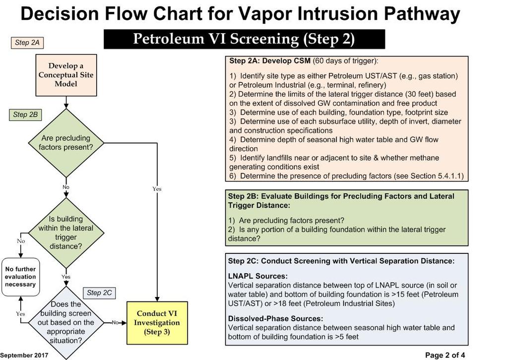
105
106
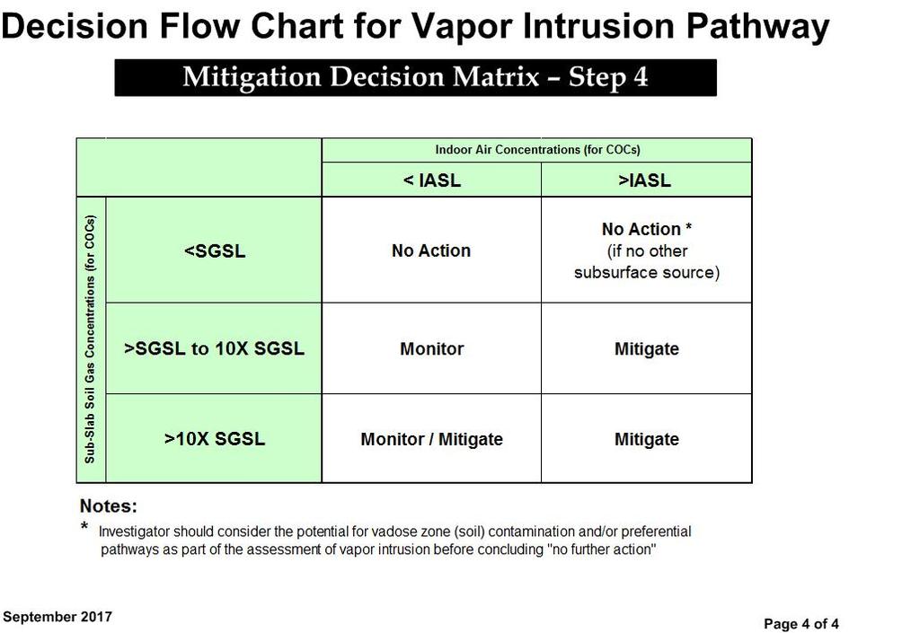
107
108 APPENDIX B Vapor Intrusion Timeline
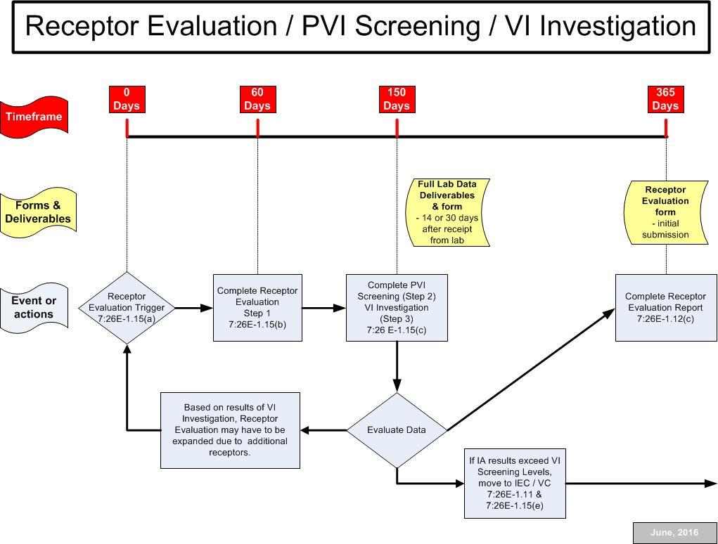
109
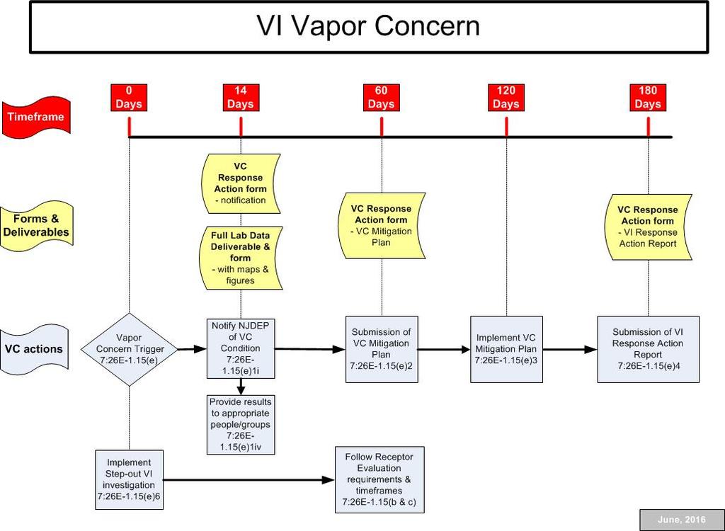
110
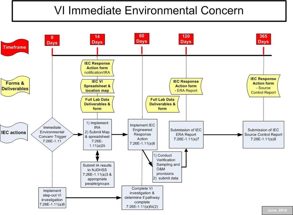
111
112 APPENDIX C ITRC Conceptual Site Model Checklist
113 CONCEPTUAL SITE MODEL (CSM) CHECKLIST The information included in this checklist may be useful for developing the site-specific conceptual migration model and in planning the soil gas sampling. The investigator may use this checklist to compile information for each site. Utilities and Process Piping Locate and map out all underground utilities near the soil or groundwater impacts; pay particular attention to utilities that connect impacted areas to occupied buildings Locate and map out all underground process piping near the soil or groundwater impacts. Buildings (Receptors) Locate and map out existing and potential future buildings Identify the occupancy and use of the buildings (e.g., residential, commercial) (may need to interview occupants to obtain this information) Describe the construction of the building including materials (e.g., wood frame, block,), openings (e.g., windows, doors), and height (e.g., one-story, two-story, multiple-story); identify if there is an elevator shaft in the building (if applicable) Describe the foundation construction including: Type (e.g., basement, crawlspace, slab on grade) Floor construction (e.g., concrete, dirt) Depth below grade. Describe the HVAC system in the building including: Furnace/air conditioning type (e.g., forced air, radiant) Furnace/air conditioning location (e.g., basement, crawlspace, utility closet, attic, roof) Source of return air (e.g., inside air, outside air, combination) System design considerations relating to indoor air pressure (e.g., positive pressure is often the case for commercial buildings). Describe sub-slab ventilation systems or moisture barriers present on existing buildings, or identify building- and fire-code requirements for sub-slab ventilation systems (e.g., for methane) or moisture barriers below foundations.
114 Source Area Locate and map out the source area for the vapor-phase contaminants related to the subsurface vapor intrusion pathway Describe the presence, distribution, and composition of any NAPL at the site Identify the vapor-phase contaminants that are to be considered for the subsurface vapor intrusion pathway Describe the status and results for the delineation of contamination in environmental media, specifically soil and groundwater, between the source area and the potentially impacted buildings Describe the environmental media (e.g., soil, groundwater) containing contaminants Describe the depth to source area Describe the potential migration characteristics (e.g., stable, increasing, decreasing) for the distribution of contaminants. Geology/Hydrogeology Review all boring logs, monitoring well construction, and soil sampling data to understand the following: Heterogeneity/homogeneity of soils and the lithologic units encountered and the expected/observed contaminant migration o Depth and lateral continuity of any confining units that may impede contaminant migration o depth and lateral continuity of any highly transmissive units that may enhance contaminant migration Depth of Vadose (unsaturated) Zone, Capillary Fringe and the Phreatic (saturated) Zone o Note any seasonal water table fluctuations and seasonal flow direction changes (hydraulic gradient) o Note the depth interval between the vapor source and the ground surface o Note the presence of any perched aquifers o Where does the water table intersect well screen interval or note the presence of submerged screen Describe distinct strata (soil type and moisture content e.g., moist, wet, dry ) and the depth intervals between the vapor source and ground surface Describe the depth to groundwater Describe groundwater characteristics (e.g., seasonal fluctuation, hydraulic gradient).
115 Site Characteristics Estimate the distance from edge of groundwater plume to building Nearby potential sources Estimate the distance from vapor source area to building Describe the surface cover between the vapor source area and the potentially impacted building
116 APPENDIX D Indoor Air Building Survey and Sampling Form
117 New Jersey Department of Environmental Protection INDOOR AIR BUILDING SURVEY and SAMPLING FORM Preparer s name: Preparer s affiliation: Date: Phone #: Site Name: Case #: Part I - Occupants Building Address: Building Block: Lot: Property Contact: Owner / Renter / other: Contact s Phone: home ( ) work ( ) cell ( ) Part II Building Characteristics Building type: residential / multi-family residential / office / strip mall / commercial / industrial Describe building: Sensitive population: day care / nursing home / hospital / school / other (specify): Number of floors below grade: (full basement / crawlspace / slab on grade) Approx. depth of basement below grade surface: ft. Basement size: ft 2 Basement floor construction: concrete / dirt / floating / stone / other (specify): Foundation walls: poured concrete / cinder blocks / stone / other (specify) Basement sump present? Yes / No Sump pump? Yes / No Water in sump? Yes / No Are the basement walls or floor sealed with waterproof paint or epoxy coatings? Yes / No Is there a whole house fan? Yes / No Type of ground cover outside of building: grass / concrete / asphalt / other (specify) Existing subsurface depressurization (radon) system in place? Yes / No active / passive Sub-slab vapor/moisture barrier in place? Yes / No Type of barrier: Part III Indoor Contaminant Sources Identify all potential indoor sources found in the building (including attached garages), the location of the source (floor and room), and whether the item was removed from the building 48 hours prior to indoor air sampling event. Any ventilation implemented after removal of the items should be completed at least 24 hours prior to the commencement of the indoor air sampling event.
118 Potential Sources Location(s) Removed (Yes / No / NA) Gasoline storage cans Gas-powered equipment Kerosene storage cans Moth balls Air fresheners Fuel tank (inside building) Wood stove or fireplace New furniture / upholstery New carpeting / flooring Hobbies - glues, paints, etc. LIST OTHER IMPORTANT SOURCES IDENTIFIED: NA NA NA Part IV Miscellaneous Items Do any occupants of the building smoke? Yes / No How often? Last time someone smoked in the building? hours / days ago Does the building have an attached garage directly connected to living space? Yes / No If so, is a car usually parked in the garage? Yes / No Are gas-powered equipment or cans of gasoline/fuels stored in the garage? Yes / No Do the occupants of the building have their clothes dry cleaned? Yes / No If yes, how often? weekly / monthly / 3-4 times a year Do any of the occupants use solvents in work? Yes / No If yes, what types of solvents are used? If yes, are their clothes washed at work? Yes / No Has painting or staining been done in the building in the last 6 months? Yes / No If yes, when and where? Provide any information that may be pertinent to the sampling event and may assist in the data interpretation process.
119 Part V Sampling Information Sample Technician: Phone number: ( ) - Company: Sample Source: Indoor Air / Sub-Slab / Near Slab Soil Gas / Exterior Soil Gas Were Instructions for Occupants followed? Yes / No If not, describe modifications: Sample locations (floor, room): Sample # Location Analytical Method Sample Volume Sample Time Sample Date Sampler Type Ambient Temp ( F) Drawing of Sample Location(s) in Building Type of field instrument used (include summary of results): Part VI - Meteorological Conditions Was there significant precipitation within 12 hours prior to (or during) the sampling event? Yes / No Describe the general weather conditions:
120 APPENDIX E Evaluating Indoor Air near VOC Contaminated Sites Fact Sheet
 and paint thinners are several examples of products that contain these compounds.")
121 Fact Sheet Evaluating Indoor Air near VOC Contaminated Sites What are VOC? Volatile organic compounds (VOC) are a class of chemicals that readily evaporate at room temperature. Gasoline, dry cleaning fluid, degreasing agents (solvents) and paint thinners are several examples of products that contain these compounds. VOC may be found in soil and/or ground water due to spillage onto the ground, leaks from underground storage tanks and other types of discharges. How VOC in soil or ground water can affect indoor air If VOC contaminate soil or ground water at a site, it is important to evaluate nearby buildings for possible impacts from vapor intrusion. Vapor intrusion occurs when gases from the contaminated soil or ground water seep through cracks and holes in foundations or building slab and accumulate in basements, crawlspaces or living areas (see diagram below). A variety of factors can influence whether vapor intrusion will occur at a building located near soil or ground water contaminated with VOC. These include, but are not limited to, the concentration of the VOC, the type of soil, the depth to ground water, the building construction, the condition of the foundation or slab and the existence of underground utilities that create pathways for vapors to travel. Short term exposure to high levels of organic vapors can cause eye and respiratory irritation, headache and/ or nausea. Breathing low levels of organic vapors over a long period of time may increase an individual s risk for respiratory ailments, cancer and other health problems. Organic vapors can be present inside a building at potentially harmful levels without being detectable by odor. Sub-slab soil gas testing, near-slab soil gas testing and/or indoor air testing are usually required to determine whether vapor intrusion is occurring at a property. Testing for vapor intrusion If your home or building is located near VOC-contaminated soil or ground water, NJDEP or an environmental contractor may ask permission to evaluate your property for vapor intrusion. This process typically involves first conducting sub-slab soil gas testing to check for vapors beneath the (over) Indoor Air basement crawl-space slab Organic Vapors VOC Contaminated Soil VOC Contaminated Ground Water Ground Water Table Diagram adapted from USEPA s Draft Guidance for Evaluating the Vapor Intrusion to Indoor Air Pathway from Ground Water and Soils, November 2002 New Jersey Department of Environmental Protection Site Remediation Program
 is collected using an evacuated air testing")
122 building, followed by indoor air testing, if necessary. During subslab testing, a small hole is bored through the basement floor or slab and a sample of the soil gas (the air trapped between the soil particles) is collected using an evacuated air testing canister (see below). If it is not possible to collect a soil gas sample from beneath the floor or slab, the sample may be collected by placing a probe in the soil directly adjacent to the building (near-slab testing). The soil gas sample is then sent to a certified laboratory to be analyzed for VOC. If the analysis shows VOC related to the subsurface contamination are present above NJDEP s Soil Gas Screening Levels (SGSL), then indoor air testing is necessary. During indoor air testing, a canister is placed in the basement, crawlspace or other part of the building for a period (normally 24 hours). If the analysis of the indoor air sample shows VOC related to the subsurface contamination are present above NJDEP s Indoor Air Screening Levels (IASL), vapor intrusion is likely occurring. Additional evaluation of the property may be needed to confirm this finding. Background contamination Many materials and substances commonly found in commercial and residential settings, such as paints, paint thinners, gasoline-powered machinery, certain building materials and cleaning products, dry cleaned clothing and cigarette smoke, contain VOC that may be detected by indoor air testing. Even VOC from motor vehicle emissions and other outdoor sources can contaminate indoor air. When VOC from these sources are detected during indoor air testing, they are referred to as background contamination. It is sometimes difficult to determine whether the VOC detected inside a building are due to vapor intrusion, background contamination or a combination of both. Before your building is evaluated for vapor intrusion you should receive a copy of NJDEP s Instructions for Occupants Indoor Air Sampling Events. Please follow these instructions to minimize background contamination and help ensure that the test results are as definitive as possible. Addressing vapor intrusion If testing confirms vapor intrusion is causing potentially harmful levels of VOC to accumulate inside a building, a subsurface depressurization system may be installed at the property. The system prevents vapors from entering the building by continuously venting the contaminated air beneath the basement slab or crawlspace to the exterior of the structure. Subsurface depressurization systems are also used throughout the country to reduce levels of naturally occurring radon gas in buildings. See NJDEP s fact sheet titled Subsurface Depressurization Systems for more information about how these systems work. Instructions for Occupants Indoor Air Sampling Events, the Subsurface Depressurization Systems fact sheet and general information about vapor intrusion can be found in NJDEP s Vapor Intrusion Technical Guidance, or the Department s website at guidance/vaporintrusion. Information for Residents and Property Owners Contact Name Agency/Company Phone Number Address Sampling Date/Time Notes/Instructions An evacuated air testing canister. The pressure inside the canister is initially set lower than the indoor air, causing air to flow into the canister when the valve is opened. March 2011
123 APPENDIX F Instructions for Occupants Indoor Air Sampling Events (English and Spanish)
124 New Jersey Department of Environmental Protection Site Remediation Program Instructions for Occupants for Indoor Air Sampling Representatives of will be collecting one or more indoor air samples from your building in the near future. Your assistance is requested during the sampling program in order to collect an indoor air sample that is both representative of indoor conditions and avoids the common background indoor air sources associated with occupant activities and consumer products. Please follow the instructions below starting at least 48 hours prior to and during the indoor air sampling event: Operate your furnace and whole house air conditioner as appropriate for the current weather conditions Do not use wood stoves, fireplaces or auxiliary heating equipment Do not open windows or keep doors open. Avoid using window air conditioners, fans or vents Do not smoke in the building Do not use air fresheners or odor eliminators Do not use paints or varnishes (up to a week in advance, if possible) Do not use cleaning products (e.g., bathroom cleaners, furniture polish, appliance cleaners, all-purpose cleaners, floor cleaners) You will be asked a series of questions about the structure, consumer products you store in your building, and occupant activities typically occurring in the building. These questions are designed to identify background sources of indoor air contamination. While this investigation is looking for a select number of chemicals related to the subsurface contamination, the laboratory will be analyzing the indoor air samples for a wide variety of chemicals. As a result, chemicals such as tetrachloroethene that is commonly used in dry cleaning or acetone found in nail polish remover might be detected in your sample results. Do not use cosmetics, including hair spray, nail polish remover, perfume, etc. Avoid bringing freshly dry cleaned clothes into the building Do not engage in hobbies indoors that use solvents Do not apply pesticides Do not store containers of gasoline, oil or petroleum based or other solvents within the building or attached garages (except for fuel oil tanks) Do not operate or store automobiles in an attached garage Do not operate gasoline powered equipment within the building, attached garage or around the immediate perimeter of the building Your cooperation is greatly appreciated. If you have any questions about these instructions, please feel free to contact at Typical air sampling canister
 o una firma de consultoria ambiental estaran colectando una o mas muestras de aire del interior de su edificio.")

125 New Jersey Department of Environmental Protection Site Remediation Program Instrucciones Para Ocupantes Eventos de Muestreo de Aire de Interiores En un futuro cercano, representantes del Departamento de Protección Ambiental de Nueva Jersey (NJDEP) o una firma de consultoria ambiental estaran colectando una o mas muestras de aire del interior de su edificio. NJDEP requiere de su ayuda para colectar una muestra del interior en su estructura que a la vez es representativa de las condiciones del interior y el evitar las fuentes comunes de antecedentes de contaminación de aire asociado con actividades de la casa y productos de consumo. Por favor siga las instrucciones abajo mencionadas comenzando por lo menos 48 horas antes de y durante el evento de muestreo: Opere su horno y el aire acondicionado de toda la casa apropiadamente a las actuales condiciones del tiempo No use estufas de leña, chimeneas o equipos auxiliares de calefacción. No abrir las ventanas o mantener las puertas abiertas. Evite usar aires acondicionados, abanicos o ventiladores de ventanas No fume dentro del edificio No use refrescantes de aire o eliminadores de olor No use pinturas o barniz (hasta una semana por adelantado, si es posible) No use productos de limpieza (ej. Limpiadores de baño, cera para muebles, limpiadores de aparatos electrodomésticos, limpiadores para todo propósito, limpiadores del piso) Se le hara una serie de preguntas acerca de la estructura, productos de consumo que usted almacena en su edificio, y actividades de la casa típicamente ocurriendo dentro del edificio. Esas preguntas son diseñadas para identificar antecedentes de fuentes de contaminación de aire dentro del edificio. Mientras esta investigación esta buscando por un selecto número de químicos relacionados a la contaminación de la sub superficie, el laboratorio estará analizando las muestras de aire del interior por una variedad de químicos. Así, tetrachloroethene usado en tintorerías o acetona encontrada en el removedor de esmalte de uñas podria ser encontrado en los resultados de su muestra. No use cosméticos, incluyendo fijador del cabello, removedor de esmalte de uñas, perfume Evite traer ropa recientemente limpiada en seco (de la tintorería) al edificio No participe en pasatiempos en el interior del edificio que usen solventes No aplique pesticidas No almacene envases de gasolina, aceite o derivados de petróleo u otros solventes dentro del edificio o garajes adjuntos (con exepción de tanques de aceite de combustible - fuel oil ) No opere o almacene automoviles en un garaje adjunto No opere equipos impulsados por gasolina dentro del edificio, garaje adjunto o alrededor de los perímetros inmediatos del edificio Su cooperación es grandemente apreciada. Si usted tiene alguna pregunta acerca de estas instrucciones, por favor sienta la libertad de contactar a LSRP al.
126 APPENDIX G Derivation and Application of Vapor Intrusion Screening Levels
127 Derivation and Application of the Vapor Intrusion Screening Levels The investigator should gather and evaluate sampling results or other data to assess the vapor intrusion (VI) pathway relative to the Department s screening levels using the multiple lines of evidence (MLE) approach discussed in Chapter 4 to determine whether the pathway triggers investigation or mitigation. The Department has developed screening values for ground water, soil gas and indoor air (IA). The Department s Vapor Intrusion Screening Levels (VISL) are located in Tables 1 through 3 on the Department s VI website at The website includes the VISL Basis and Background document (Update to the VI Screening Levels) that presents the equations and input parameters used in the derivation of the screening levels. Contact the Department to determine whether a VISL can be developed for a site VI contaminant of concern (COC) if a value does not currently exist in the above tables. The NJDEP contact list for questions on the VI pathway and VISL may be accessed at G.1 Ground Water Screening Levels (GWSL) Pursuant to the Technical Rules (NJDEP 2012), ground water data shall be compared to the GWSL (N.J.A.C. 7:26E-1.15) presented in Table 1. The GWSL may be used in the evaluation of a site where the ground water is as close as two feet below the building slab when the following occurs: 1) the seasonal high water table does not reach the building slab; 2) the water table does not extend into fill material directly under the building slab; and 3) the top of the capillary zone does not reach the building slab. Pertaining to Item 3 above, the capillary zone does not normally extend through the base course layer under the slab. For situations where no fill material is present under a building s slab, estimate the top of the capillary zone based on the anticipated soil texture present. Based on an evaluation of the various soil types using the J&E model (Johnson & Ettinger 1991), the capillary zone has been determined to be greater than two feet in height for finer soils. As a result, the distance between the water table and the building slab should be at least 2.7 feet for clay soils, 4.4 feet for silty clay loam, 5.3 feet for silt and 6.3 feet for silty clay soils. Site-specific field determinations may be made in these circumstances for soil texture. GWSL should not be applied where a building slab is in direct contact with competent, massive bedrock containing discrete fractured zones as vertical fractures are very likely to act as preferential pathways for vapors (e.g., creating a direct pathway for vapors between the ground water table and the building slabs). Use the GWSL for soil that contains gravel since vapors will diffuse through the finer soil texture in the soil column. Apply the GWSL where the water table is in bedrock and nearby site-specific data indicate there is unsaturated soil, fill or geologic material below a building slab through which subsurface air flow would approximate, or approach, porous media conditions. In many areas bedrock in the vadose zone and at the water table is so highly weathered and/or densely fractured that these conditions will be met even if deeper, more competent bedrock creates very heterogeneous flow conditions. G-1
128 In situations where it is inappropriate to utilize the GWSL, the investigator should employ other lines of evidence (e.g., SSSG, near slab soil gas and IA samples) as discussed in Sections 3.3 & 3.5 of this document and the Vapor Intrusion Pathway: A Practical Guideline (ITRC 2007). G.2 Soil Gas Screening Levels (SGSL) The SGSL in Table 1 shall be compared to sub-slab and/or near slab soil gas results (N.J.A.C. 7:26E- 1.15). Use the SGSL in the evaluation of representative and appropriate (see Chapter 3) soil gas analytical results. Exceedance of the SGSL indicates the potential for VI that necessitates further evaluation of the pathway as outlined in Chapter 4 of this guidance. Soil gas results that do not exceed the SGSL may or may not suggest further investigation. Refer to Section 3.3 for additional information. G.3 Indoor Air Screening Levels (IASL) The results of IA samples shall be compared to the IASL (N.J.A.C. 7:26E-1.15) listed in Table 1. The values include residential and non-residential IASL that are used in the evaluation of IA results. Consistent with the Department s Remediation Standards (N.J.A.C. 7:26D), the residential IASL are used in the evaluation of residential properties, schools and childcare facilities (NJDEP 2015a). The non-residential IASL are applicable to commercial/industrial facilities where a discharge to the environment has occurred and the facility (or portion of the facility) is not currently handling or using the subsurface COC associated with the discharge. While the collection of IA samples is generally not recommended in situations where the facility is currently using the same COC for the VI pathway, IA samples collected under these circumstances should include consideration of both the non-residential screening levels and the applicability of the Occupational Safety and Health Administration (OSHA) permissible exposure limit (PEL) to the subject building. Air samples collected from a building crawlspace are also compared to the residential or non-residential IASL to determine whether further investigation is necessary (e.g., collecting IA samples from the usable space above the crawlspace). The subsequent IA sample results are then compared to the applicable IASL to determine whether an immediate environmental concern (IEC) or vapor concern (VC) condition for the VI pathway exists. Address the potential for a future change in use of the building or in the use of the COC within the building in situations wherein non-residential IASL and/or the OSHA PEL are used. Typically this involves periodic verification of both the use of the building and the COC that will be necessary as part of institutional control requirements at the affected building. G.4 Indoor Air Rapid Action Levels (RAL) Residential and non-residential indoor air RAL have been developed by the Department for use in evaluating IA data to determine whether prompt action is necessary within a building impacted by VI. The RAL are presented in Table 2 of the Vapor Intrusion Screening Levels Tables. Evaluation of IA data shall include a determination as to whether an IEC or VC for the VI pathway exists in a building (N.J.A.C. 7:26E-1.11). A VC for the VI pathway is identified when IA results exceed the applicable IASL, are less than or equal to the applicable RAL and are related to a completed VI pathway. An IEC G-2
129 determination is based on exceedance of the applicable RAL from a completed VI pathway. The Department s Immediate Environmental Concern Technical Guidance document may be accessed at for IEC related requirements (NJDEP 2015b). A VC or IEC does not exist at a building (or portion of a building) when OSHA applicability has been determined. This position assumes that the workers in question are fully covered by OSHA regulations (e.g., notification, training in personal protective clothing and gear, medical monitoring). The investigator should document use of the OSHA PELs. G.5 Health Department Notification Levels (HDNL) HDNL, previously developed in consultation with the New Jersey Department of Health (NJDOH), are no longer in effect. Pursuant to the Technical Requirements (N.J.A.C.7:26E-1.15(h)) all indoor and ambient air data are submitted to the NJDOH for review of the data and evaluation as to further or possible emergency actions. Evacuation and remediation are independent processes that are determined by the NJDOH and NJDEP, respectively. G.6 Site-Specific Options The investigator may utilize site-specific options, such as the development of Alternative VISL as part of the VI investigation. NJDEP contacts regarding questions on the development of alternative screening levels may be accessed at NJDEP s critique of the basis and proposed use of Alternative VISL is suggested prior to implementation of the Alternative VISL at a site or area of concern (AOC). Use of Alternative VISL without the Department s prior critique may be subject to additional technical evaluation by the Department. Alternative VISL used at a site or AOC must be indicated on the applicable form (NJDEP Alternative Soil Remediation Standard and/or Screening Level Form) that can be accessed at The basis for the site-specific parameters or conditions used in the development of Alternative VISL, along with the application of the alternative values at a site or AOC, are documented and submitted to the Department with the form. Alternative VISL may be developed based on site-specific factors not reflected in the Department s default VISL. As an example, an Alternative IASL may be developed for a site or AOC based on minimal use of a non-residential building that results in limited exposure to workers in the building. Appropriate control and monitoring of the limited use, along with the application of an institutional control, would be necessary to ensure that the alternative screening level remains protective. The investigator may contact the Department regarding any questions they may have on the development of Alternative VISL. For Alternative GWSL, NJDEP guidance on modifying input parameters in the J&E spreadsheet should be consulted ( In addition, while the GWSL in Table 1 of the Vapor Intrusion Screening Level Tables are based on the presence of sandy soils, the Department has developed GWSL for Alternate Soil Textures, found in Table 3 of the Vapor Intrusion Screening Levels Tables found on the Department s VI website ( utilizing loamy sand, sandy loam and loam soil that result in less stringent screening levels. For soil textures other than those listed in Table 1 or 3, the G-3
130 J&E spreadsheets may be used. Laboratory soil grain size analysis, as described below, should be documented to justify use of GWSL for Alternate Soil Textures at a site. To establish soil texture, collect soil cores using a Shelby Tube, direct push sampler, or split spoon. Two representative borings within 10 feet of the building will be sufficient for most buildings (e.g., singlefamily home) unless soil conditions vary substantially around the building. Additional soil borings are necessary for larger buildings. Collect the soil cores/samples continuously (every two or four feet depending on the length of the sampling device) from the base of the slab depth to the surface of the static water level. Texture analysis should be conducted every two feet or for each distinct soil layer. Break points between the soil layers can be determined via visual inspection of core samples for changes in soil texture and/or appearance. Gravel should be removed prior to determining soil texture by passing the sample through a 2 mm sieve. Soil aggregates should be crushed to pass through the sieve. The sand, silt and clay percentages should be calculated on the remaining material (the initial sample weight should be determined without the gravel). If the soil contains a large percentage of gravel (or other large particles or debris), vapor movement in the unsaturated zone may begin to exhibit characteristics similar to that of fractured bedrock material and the use of the alternative soil texture screening levels may not be recommended. The investigator should use professional judgment to determine if the percentage of this material is too great for use of the alternate soil texture screening levels. A variety of methods exist to determine soil texture. Sieve analysis alone is generally not adequate, because it does not separate the silt and clay fractions. The Department will consider any of the following techniques acceptable: the hydrometer method; sieve analysis for the sand and gravel portions of a given sample with pipette or hydrometer measurements of the silt and clay fractions; rapid sediment analyzers; or electro-resistance multichannel particle size analyzers. The percentages of sand, silt and clay determined by the chosen analysis techniques are then compared to the United States Department of Agriculture (USDA) Soil Texture Triangle to determine the soil texture classification (Figure G-1). The USDA Calculator at may be used to determine the applicable soil texture. Under the USDA Soil Texture Triangle, sands are considered particles between 0.05 mm and 2 mm in size, silts are between 0.05 mm and mm and clays are less than mm in size (USDA 1987). G-4
131 Figure G-1 Soil Classification System (USDA) Among the standard methods for determining particle size distribution, two methods are recommended: ASTM Method D (ASTM 2007b) and ASTM Method F (ASTM 2010). Other standard methods are acceptable if they determine the USDA soil texture. ASTM Method D is a sieve and hydrometer method. First the sand fraction is determined using a mm sieve. Then, the remaining sample is suspended in water and the density of the suspension is measured after the silt has settled, which allows determination of the silt and clay fractions of the sample. This method uses a mm cutoff for the sand fraction, rather than the USDA 0.05 mm cutoff. It is recommended, although not required, that a 0.05 mm sieve be substituted. The default hydrometer analysis for this method determines <0.001 mm (colloids) and <0.005 mm fractions, while the USDA clay fraction is <0.002 mm. If the <0.002 mm fraction is not determined directly, it may be estimated by averaging the results from the <0.001 mm and <0.005 mm fractions. The other ASTM method, F (ASTM 2010), is a sieve and pipette-based method. This method has the advantage of properly determining the sand, silt and clay percentages according to the USDA particle size definitions. Sand is first separated using a 0.05 mm sieve. Then, the remaining sample is suspended in water, and the suspended clay is sampled with a pipette after allowing the silt fraction to settle. The clay is determined by weight after drying, and the silt content is then determined by subtracting the sand and clay weight from the total sample weight. In order to use the Alternative GWSL shown in Table 3 of the Vapor Intrusion Screening Level Tables or those based on other site-specific soil textures, laboratory soil grain size analysis should be used to G-5
132 determine a median USDA soil texture for the unsaturated soil zone. A median soil texture means that half of the vertical soil column height should exhibit a texture coarser than or equal to the selected soil texture, and the other half of the soil column should have a texture finer than or equal to the selected soil texture. If it is desired to more accurately model multiple soil layers in the soil column, the NJDEP J&E model spreadsheets may be used. Consult the separate instructions for those spreadsheets that can be accessed at ( G-6
133 APPENDIX H QA/QC for Sub-Slab Soil Gas and Indoor Air Sampling
134 Quality Assurance /Quality Control for Sub-Slab Soil Gas and Indoor Air Sample Collection H.1 Quality Assurance/Quality Control (QA/QC) Procedures for VI Sampling The objective of field sampling in support of a vapor intrusion (VI) investigation is to obtain a representative sample of the matrix for analysis without altering the physical and chemical makeup of the sample. The use of QA/QC procedures in the sampling process will provide a representative sample for analysis to base sound remedial decisions. During the entire sampling process from preparation through collection of indoor air and subslab samples, QA/QC procedures should be employed to ensure a representative sample is collected. These procedures include various checks and measurements to confirm the equipment is ready for sampling by eliminating sources of cross contamination or sample dilution. These checks and measurements include the following: Use of proper fitting tightening procedures, Pressure checks of the stainless steel canisters before and after sampling, Leak checks of the sample container, Shut-in tests of the sampling train, Collection of atmospheric data Proper installation of the annular seal for the SSP, Leak testing of the SSP annular seal, Purge volume calculations, Purging flow rates, Sampling flow rates, Sample volume and minimum stainless steel canister pressures. Canister handling times H.2 Stainless Steel Canisters H.2.1 Stainless Steel Canister Fittings Proper tightening of the air flow controller (AFC) on the stainless steel canister is the first step for eliminating leaks. A majority of the fittings on the stainless steel canisters and AFCs are compression tube fittings (e.g., Swagelok ). These fittings are designed to be disassembled and assembled many times. Tighten the fittings as follows: 1. Insert the tube with the pre-swaged ferrules into the fitting until the front ferrule seats against the fitting body (this is the sealing surface). 2. While holding the fitting body steady, rotate the nut by hand until a significant increase in resistance is encountered. If rough edges are encountered on the threads, gently use a wrench for ¼ of a turn to get over the rough edge. 3. Tighten the fitting finger tight. H-1
135 4. Using a wrench, tighten the nut a maximum of ¼ turn past finger tight. 5. The attached fitting should not move when tight. Always use two wrenches when attaching or removing fittings to prevent altering other connections or damaging equipment. Over tightening of the fittings will damage the threads and compromise sample integrity. There have been problems with threads on the stainless steel canisters and regulators being damaged due to over-tightening of the fittings. A sacrificial connector installed on the stainless steel canister will stop damage to the threads of the canister. If the connector is damaged, it can be easily replaced. A good practice for laboratories to reduce the problems with the stainless steel canister and AFC fittings is to pair a stainless steel canister with a specific AFC so the threads match and reduce leak and connection problems. Laboratories that supply canisters have reported that Teflon tape has been used on the compression fittings. Teflon tape must not be used on the compression fittings of the stainless steel canisters and AFCs. The use of Teflon tape will not help seal the fittings but, may cause a leak if the tape makes contact with the sealing surface of the compression fitting or lead to overtightening of the fittings which can compromise sample integrity or thread damage. The use of a brass or stainless steel cap on the inlet of the valve assembly of a stainless steel canister can minimize loss of vacuum if a valve is accidently opened during shipment and handling. It also prevents particulates from entering the canister valve and causing damage. H.2.2 Stainless Steel Canister Pressure Check The laboratory is required to record the vacuum in the stainless steel canister prior to shipment. Upon arrival of the stainless steel canisters from the laboratory, confirm the valve on each canister is closed. Prior to mobilizing for field sampling, check the vacuum pressure of each canister to determine if any canisters had leaked during shipment. Use a high quality vacuum gauge with minimal fittings to reduce dead air space. Attach the gauge to the stainless steel canister, quickly open and close the valve to the stainless steel canister and record the vacuum. This will identify any low vacuum cans before commencing the sampling event. Stainless steel canisters with vacuums less than 25 in-hg should not be used for sample collection because probable leakage can result in a non-representative sample. When performing this vacuum test of the canisters 1-3 days prior to sampling, the laboratory can be contacted for a replacement canister. When a low vacuum canister is discovered in the field, the sampling design must be altered possibly impacting the objective of the sampling. Use of the high quality vacuum gauge for initial canister pressure testing should not be used to verify final canister vacuum pressures due the potential for cross contamination. H.2.3 Air Flow Controller (AFC) Vacuum Gauges The vacuum gauge on the AFC is used to measure the vacuum at the start and stop of sampling. It can also be used to monitor the fill rate of the canister when collecting a time integrated sample. The gauge on the regulator is a low accuracy gauge with an accuracy of ±5 in-hg. They H-2
136 are designed to give a rough approximation of the vacuum at a low cost and be durable for field use. The official vacuum in a stainless steel canister is determined by the laboratory using a NIST-traceable (National Institute of Standards and Technology) vacuum gauge. There may be instances when the vacuum gauge on the AFC may read a positive or negative vacuum in ambient conditions. This false vacuum can be accounted for when obtaining the final vacuum measurement. Unfortunately, AFCs with a positive false vacuum will not allow for true initial vacuum since the vacuum pressure will be off-scale. This condition will result in initial readings greater than -30 in-hg of vacuum. It should be noted on the chain of custody form when this condition is encountered for an AFC. H.3 Sample Train Material of Construction and Leak Test Procedures H.3.1 Sample Train Materials of Construction The components that are used in the sampling train for soil gas and special indoor air sampling must be constructed of materials that will not impact the sample. This can occur when the materials react with the sample; or adsorb or desorb contaminants from or to the sample. Therefore, components of the sampling train must be constructed of inert materials such as stainless steel and glass and small diameter tubing (1/8 1/4 inch ID) such as ridged wall nylon, PEEK (polyether ether ketone) or PTFE (Polytetrafluoroethylene). Avoid using tubing such as Tygon, LDPE (low density polyethylene) vinyl and copper tubing due to their negative effects on sample quality. Glass and stainless steel components can be decontaminated between uses. Flexible tubing should be virgin material and disposed of after each use. H.3.2 Shut-in Test for Indoor Air Sampling Equipment A shut-in test is designed to verify there are no leaks in the connections of the stainless steel canister and the AFC. The shut-in test serves as a quality control measure to evaluate the potential of air leakage resulting in the stainless steel canister filling too quickly yielding a nonrepresentative sample. The shut-in test is best performed prior to the mobilization for sampling but can also be performed in the field. It should be completed on all IA stainless steel canisters. There are two methods for performing the shut-in test. The first method utilizes the gauge on the AFC. In a clean environment, attach the AFC to the stainless steel canister. Remove the stainless steel candy cane sample tubing from the AFC. Attach the brass dust cap from the canister to the inlet of the AFC. Quickly open and close the valve to the stainless steel canister. Observe the pressure on the AFC for 30 seconds; if the pressure remains steady, there is no air leak. If the pressure drops, there is a leak somewhere in the connections which must be tightened and the check re-run. The second method is performed by connecting a vacuum pump to the end of the stainless steel candy cane sample tubing on the AFC. Evacuate the lines to an approximate vacuum of 100 inches of water. The vacuum gauge on the AFC can be used to measure the vacuum (100 inches of water = 7.34 inches of Hg). Then seal the vacuum pump from the stainless steel candy cane by pinching off the tubing. Observe the vacuum gauge for 30 seconds. If the pressure remains H-3

137 steady, there is no air leak. If any observable loss of vacuum is noted, there is an air leak. The fittings should be retightened and the shut-in test re-run until the vacuum in the sampler does not noticeably dissipate. The laboratory supplying the AFC should be consulted prior to performing this test as it may not be amenable to certain types of AFCs. H.3.3 Leak Checks for Sub-Slab Sampling Equipment For sub-slab sampling, leak checks must be performed on the SSP and all fittings of the sampling train prior to collecting a soil gas sample. The leak check serves as a quality control measure to evaluate the potential for dilution of a sample from ambient air. Two leak checks should be performed, one for the sampling train and one for the annular seal of the SSP. H Shut-in Test of Sampling Train A shut-in test is designed to verify there are no leaks in the above-ground fittings of the sampling train. It is best performed prior to sampling mobilization, but can also be performed in the field. It is easy to perform, so it is recommended to be completed on 100% of the sampling trains. Sampling Manifold SS Canister and Flow Controller ¼ ID PTFE Sample Point Vacuum Pump Plug Figure H-1 Shut-in Test of sub-slab sampling train (NJDEP) A shut-in test consists of assembling the above-ground apparatus including the canister, AFC, valves, lines, fittings and the SSP. Plug one end of the sampling train and connect a vacuum pump to the opposite end. Evacuate the lines to an approximate vacuum of 100 inches of water. The vacuum gauge on the stainless steel canister s AFC can be used to measure the vacuum (100 inches of water = 7.34 inches of Hg). Then seal the SSP by pinching off the tubing connected to the vacuum pump or if used, close the valve of the sampling manifold. The vacuum gauge is observed for 30 seconds, and if there is any observable loss of vacuum, the fittings should be adjusted as needed and retightened until the vacuum in the above-ground portion of the sample train does not noticeably dissipate (McAlary et al. 2009). A setup of this test is shown in Figure H-1. H-4
138 The successful shut-in test of the sampling train will eliminate the need to include these components in the leak testing using a shroud over the entire sampling train (Section H.3.3.4). Only a shroud is required over the annular seal, reducing the size of the required shroud and volume of tracer gas. H Installing the Annular Seal The objective of the annular seal between the temporary or permanent SSP and the cement floor is to prevent the intrusion of ambient air into the sub-slab atmosphere during sampling, potentially diluting the sample. The annular seal can be made with clay, bentonite, cement grout or other non-chemical reacting materials. For temporary SSP installations, drill a hole in the slab using a rotary hammer with a bit the same size of the outer diameter of the sampling point tubing. After the hole is drilled, insert the sample tubing into the hole and then clean a 4-inch diameter area around the hole to remove all dust and debris. This can be completed with a wire brush followed by sweeping with a paintbrush, small whisk broom or vacuum. A damp sponge can also be used to remove any dust. If modeling or pottery clay is used to make the annular seal, it is recommended that a putty knife is employed to assist in applying the sealing material to the annular space and slab. Stainless steel sampling devices with premanufactured silicone seals that are hammered into the sampling holes are also acceptable (Vapor Pin ). If liquid sealant is used, the sample hole can be over-drilled with a inch bit to a depth of 1-2 inches to create a trough for the sealant. After insertion of the sample tubing in the over drilled hole, bentonite can be poured into the over-drilled space and allowed to set before sampling. For examples of temporary and permanent SSP installations, follow the example procedures found on the NJDEP VI website ( The annular seal is the most vulnerable to leakage since two different materials must be sealed together and movement in the sampling tubing during purging and sampling can break the seal. A T fitting can be added to the sampling train with one leg connected to the AFC, one leg connected to the sample tubing/point and the other is connected to length of tubing with a ball valve with a hose barb for purging of the sampling train. All materials must be constructed of materials that will not impact sample quality. This fitting allows for the purging and sampling of sub-slab soil gas without moving the stainless steel canister or sampling tubing. To purge the sampling train, a vacuum pump or large syringe with a 3-way valve is attached to the barb fitting on the ball valve, the valve is opened and the sample line is purged. When purging is complete, close the ball valve and open the stainless steel canister for sampling. H Leak Testing the Annular Seal To verify the integrity of the annular seal around the SSP, a leak test should be performed. The leak test is performed by introducing a tracer compound around the above ground fittings and annular seal. The soil gas sample is then analyzed for the tracer. There are a variety of tracer compounds that can be used with advantages and disadvantages to each compound. The common tracer compounds are presented in Table H-1. H-5
139 Table H-1 Sub-Slab Point Leak Detection Tracers Tracer Advantages Disadvantages Helium Can check for leaks with compound specific direct reading instrument (DRI) Can quantify leakage accurately Does not interfere with TO-15 analysis Leak is known in real time so corrections can be performed Filter on meter can remove interferences Liquid Tracers (Isopropyl Alcohol (IPA), 1, 1- Diflouroethane (DFE)). Sulfur Hexafluoride Easy to use to identify leaks Can be detected with a DRI-FID Easy to apply to sampling train connections or use in a shroud Check for leaks with onsite instrument with low detection limits Oxygen Cost effective Easy to use Analyze with compound specific DRI No supply gas required Water Cost effective Easy to use Leakage noted by visual inspection No supply gas required H-6 Must use high grade helium to avoid VOC contamination Required equipment is cumbersome Cannot be analyzed by TO-15 High methane or water vapor may yield false positives with He DRI (TCD) Qualitative Test Concentration introduced to assess leak is estimated Leak is not known until after lab analysis Large leak may interfere with TO-15 analysis No compound specific DRI available May leave residual material on sampling train Possibility of cross contamination of sampling equipment from handling the tracer compound Qualitative test Expensive, Compound specific DRI may not be readily available Field instrument subject to interference with chlorinated solvents Cannot be analyzed by TO-15 A greenhouse gas Qualitative test Cannot be used where ambient oxygen concentrations are anticipated Qualitative test If leak is noted, a new hole must be drilled Not all foundations amenable to test
140 H Liquid Tracers The most common liquid tracer compounds used are IPA or 1,1-difluoroethane. Soak towels with the liquid tracer compound and place them over the annular seal. If a shut-in test was not performed on the sampling train, the connection of the SSP to the sampling train and fittings on the sampling train can be tested in the same manner as with the liquid tracer. The leak check compound must be included in the analysis of the soil gas sample. If there is no leak, the tracer gas will be absent. The disadvantage is the leak is not known until after the analysis of the soil gas sample. Therefore, this method is best used with a field analytical method so if a leak is detected, it can be repaired and re-tested to enable the collection of a representative sample. When using liquid tracers, the starting concentration either is assumed as equal to the vapor pressure of the compound at ambient temperature or can be measured if on-site analysis is available. For example, using a liquid tracer such as isopropanol, a 10% leak would give a value in the sample of approximately 10,000 µg/l (mg/m 3 ), assuming a starting concentration equivalent to its vapor pressure (40,789 ppmv). For liquid tracers, to account for the probability that the starting concentration is not equal to the vapor pressure, NJDEP will establish a concentration level that corresponds to a 0.1% leak, assuming a starting concentration equal to the vapor pressure of the compound or a 1% leak if the starting concentration is only 10% of the vapor pressure, a conservative assumption (ITRC 2007). In the above example for isopropanol, a concentration of 100 µg/l or greater in the sample would indicate a leak. An alternative method for using liquid tracers is to use the liquid tracer in a shroud. Place the liquid tracer in a small pan or crucible and place a shroud over the entire sampling train or the annular seal and seal it with clay, tape or other material to the floor to minimize air infiltration. Allow the tracer compound to evaporate and equilibrate, then analyze a sample from inside the shroud. Testing can be performed with field analytical methods or by the laboratory. If field analytical methods are not used, the leak check compound must be included in the analysis of the soil gas sample. With the stainless steel canister closed, use a gas sampling bag to collect a soil gas sample through the sampling train. A leak is occurring when the tracer gas concentration in the soil gas sample is greater than 5% of the concentration within the shroud. In this case, the leak must be fixed and the leak check repeated. If the concentration of the tracer gas is 5% or less, the sample is considered to have no leak in the sampling system. H Water Dam An alternative to gas tracers is use of a water dam. The water dam consists of a short piece of 2-4 PVC pipe placed around the SSP and sealed to the floor with modeling clay or other VOC free, inert material that will hold water. The pipe must be placed around the SSP tubing before connecting. Once the SSP and seal are inplace, the PVC tubing is brought down over the point and sealed to the slab creating an enclosure around the point. The inner space is then filled with distilled/deionized water so it is over the top of the annular seal. Start purging the SSP. If the water level remains stable, the annular seal is good. If there is a drop in the water level in the H-7

141 water dam or water is observed entering the sampling tubing, stop purging immediately. Water can permanently damage the stainless steel canister. With a failed test, the SSP hole must be sealed, a new SSP hole drilled and the test repeated. If the water level remains stable, purge the SSP of the required volume then proceed with sampling. Maintain monitoring of the water level in the water dam to ensure it remains sealed and to eliminate possible damage to equipment. Not all foundations lend themselves to this method: the foundation material may be uneven, damaged or the surface or may be covered with carpet or other materials not conducive to standing water. Figure H-3 SSP evacuation with pump, in-line T fitting and water dam leak check (NJDEP) If multiple SSP are installed during a sampling round, and leak tests performed on the annular seals of the initial SSP indicate integrity, the investigator may reduce the number of points that are tested. H.4 Sampling Flow Rate H.4.1 Indoor Air Sampling Flow Rates For the Department s currently approved TO-15 Methods, 6-Liter stainless steel canisters shall be used for the IA sample collection. Alternative sizes or types of sample containers are not acceptable for IA samples per the TO-15 analytical method. Other certified air methods, such as TO-17 may also be employed, where appropriate. Residential IA samples should be collected over a 24-hour period. Flow rates for TO-15 are set by the laboratory to match sampling time (e.g., 24 hours) and canister volume. The rate is about mls/minute for a 6-liter canister. Therefore, the sample time should be established with the laboratory in advance of the sampling event, so the laboratory can provide the proper settings on the air flow controller. The AFC is designed to maintain a constant flow rate with a canister H-8
Best management practices for vapor investigation and building mitigation decisions
 www.pca.state.mn.us Best management practices for vapor investigation and building mitigation decisions Purpose This best management practices (BMPs) document describes the processes used to conduct vapor
EPA S 2015 vapor intrusion guides What do they mean for your facility?
 Environmental law alert Nixon peabody LLP July 22, 2015 EPA S 2015 vapor intrusion guides What do they mean for your facility? By J. Timothy Ramsey and Jean McCreary The United States Environmental Protection
Is this the maturation Phase of Vapor Intrusion Investigations?
 Is this the maturation Phase of Vapor Intrusion Investigations? Presenter: Will Elcoate June 27 th, 2012 EPA Moves forward with Vapor Intrusion EPA plans to tear down three city businesses Columbus Telegram
August Vapor Intrusion Guidance FAQs
 August 2017 2017 Vapor Intrusion Guidance FAQs Topics: A. General B. Effect of New Guidance on In-Process Sites C. Future Use of Site D. Modeling E. Off-Site Properties F. Preferential Pathways G. Proximity
Proposed Changes to EPA s Spreadsheet Version of Johnson & Ettinger Model (and some new spreadsheet tools)
") Proposed Changes to EPA s Spreadsheet Version of Johnson & Ettinger Model (and some new spreadsheet tools) Workshop Integrating Observed & Modeled Vapor Attenuation The 15th Annual AEHS West Coast Conference,
Proposed Changes to EPA s Spreadsheet Version of Johnson & Ettinger Model (and some new spreadsheet tools) Workshop Integrating Observed & Modeled Vapor Attenuation The 15th Annual AEHS West Coast Conference,
November 8, 2016 International Petroleum Environmental Conference. Tim Nickels Pastor, Behling & Wheeler, LLC
 November 8, 2016 International Petroleum Environmental Conference Tim Nickels Pastor, Behling & Wheeler, LLC Long term, non-voluntary constant inhalation exposure to toxic compounds Non-voluntarily inhale
Vapor Intrusion Regulatory Guidance and IRIS Updates with Mitigation Case Studies. Richard J. Rago Haley & Aldrich 20 June 2012
 Vapor Intrusion Regulatory Guidance and IRIS Updates with Mitigation Case Studies Richard J. Rago Haley & Aldrich 20 June 2012 Outline Vapor Intrusion Overview and VI Regulatory Landscape Recent Changes
Oregon Guidance for Assessing and Remediating Vapor Intrusion in Buildings
 Department of Environmental Quality Overview of Oregon Guidance for Assessing and Remediating Vapor Intrusion in Buildings Brownfields and Land Revitalization 2011 Conference Spokane, Washington May 13,
PA Vapor Intrusion Guidance
 PA Vapor Intrusion Guidance Society of Women Environmental Professionals Capital Chapter November 10, 2016 Presented by: Carolyn Fair - Land Recycling Program PA Department of Environmental Protection
MEMO. Kris Hinskey
 To: Paul Owens, District Supervisor MDEQ SE Michigan District Office 27700 Donald Court Warren, Michigan 48092-2793 owensp@michigan.gov Copies: Brandon Alger MDEQ Gerald Tiernan - MDEQ Todd Walton Ford
7.0 EVALUATION OF REMEDIAL ALTERNATIVES
 7.0 EVALUATION OF REMEDIAL ALTERNATIVES This section provides a description of the developed remedial alternatives based on viable remedial technologies and process options, as identified in Section 4.0,
Excavation of petroleum-contaminated soil and tank removal sampling Petroleum Remediation Program
 www.pca.state.mn.us Excavation of petroleum-contaminated soil and tank removal sampling Petroleum Remediation Program This document describes the requirements for excavating petroleum-contaminated soil
EPA s Final Vapor Intrusion Guidance
 EPA s Final Vapor Intrusion Guidance Introductory Webinar for EPA Staff by Richard Kapuscinski Office of Land & Emergency Management (OLEM) October 2017 1 I. What is Vapor Intrusion and Why Does it Matter?
Empirical Data to Evaluate the Occurrence of Sub-slab O 2 Depletion Shadow at Petroleum Hydrocarbon- Impacted Vapor Intrusion Sites
 Empirical Data to Evaluate the Occurrence of Sub-slab O 2 Depletion Shadow at Petroleum Hydrocarbon- Impacted Vapor Intrusion Sites Ravi Kolhatkar, Emma Hong Luo & Tom Peargin Chevron Energy Technology
U.S. EPA s Vapor Intrusion Database: Preliminary Evaluation of Attenuation Factors
 March 4, 2008 U.S. EPA s Vapor Intrusion Database: Preliminary Evaluation of Attenuation Factors Office of Solid Waste U.S. Environmental Protection Agency Washington, DC 20460 [This page intentionally
A REVIEW OF VAPOR INTRUSION GUIDANCE BY STATE
 A REVIEW OF VAPOR INTRUSION GUIDANCE BY STATE Laurent C. Levy, Ph.D., P.E., Gradient Senior Project Manager Webinar Tuesday, August 14, 2012 Northeast Waste Management Officials' Association Gradient Gradientcorp.com
Groundwater Monitoring Requirements of the CCR Rule What s Next?
 2017 World of Coal Ash (WOCA) Conference in Lexington, KY - May 9-11, 2017 http://www.flyash.info/ Groundwater Monitoring Requirements of the CCR Rule What s Next? Thomas A. Mann, PE SynTerra Corporation,
DRAFT Alberta Risk Management Plan Guide
 1 2 3 4 5 6 7 8 9 10 11 12 13 14 15 16 17 18 19 20 21 22 23 24 25 26 27 28 29 30 31 DRAFT FOR REVIEW PURPOSES ONLY DO NOT QUOTE, CITE, POST, PUBLISH, LINK, or HYPERLINK DRAFT Alberta Risk Management Plan
Evaluation of Spatial and Temporal Variability in VOC Concentrations at Vapor Intrusion Investigation Sites.
 Evaluation of Spatial and Temporal Variability in VOC Concentrations at Vapor Intrusion Investigation Sites. Proceeding of Air & Waste Management Association s Vapor Intrusion: Learning from the Challenges,
Vapor Intrusion Mitigation Methods & Strategies
 Vapor Intrusion Mitigation Methods & Strategies NEWMOA Workshop on Vapor Intrusion Chelmsford, MA April 12, 2006 David J. Folkes P.E. Topics Overview of Mitigation Approaches Commercial Buildings Sub-Slab
February 23, 2010 Version 0.0
 February 23, 2010 Version 0.0 New Jersey Department of Environmental Protection Site Remediation Program Guidance for Light Non-aqueous Phase Liquid (LNAPL) Free Product Initial Recovery and Interim Remedial
RECYCLED ASPHALT PAVEMENT AND ASPHALT MILLINGS (RAP) REUSE GUIDANCE MARCH 2013 (VERSION 1.0)
 REUSE GUIDANCE MARCH 2013 (VERSION 1.0)") RECYCLED ASPHALT PAVEMENT AND ASPHALT MILLINGS (RAP) REUSE GUIDANCE MARCH 2013 (VERSION 1.0) RECYCLED ASPHALT PAVEMENT AND ASPHALT MILLINGS (RAP) REUSE GUIDANCE MARCH 2013 A. GENERAL INFORMATION It is
RECYCLED ASPHALT PAVEMENT AND ASPHALT MILLINGS (RAP) REUSE GUIDANCE MARCH 2013 (VERSION 1.0) RECYCLED ASPHALT PAVEMENT AND ASPHALT MILLINGS (RAP) REUSE GUIDANCE MARCH 2013 A. GENERAL INFORMATION It is
Methane concentrations are measured using portable gas detection instruments, usually a methane meter or explosimeter which has a readout in either
 Methane gas produced by decomposing solid wastes can become an explosion hazard (see Section 6A - Solid Waste Decomposition). Methane monitoring is required at every Wyoming sanitary landfill to ensure
VAP Introduction to the Voluntary Action Program. Division of Emergency and Remedial Response
 VAP 101 - Introduction to the Voluntary Action Program Division of Emergency and Remedial Response Ohio EPA Voluntary Action Program Created in 1994 Ohio Revised Code (ORC) 3746 Final Rules went into effect
GUIDE FOR THE SUBMISSION OF REMEDIAL ACTION WORKPLANS
 GUIDE FOR THE SUBMISSION OF REMEDIAL ACTION WORKPLANS State of New Jersey Christine Todd Whitman Governor New Jersey Department of Environmental Protection Robert C. Shinn, Jr. Commissioner Site Remediation
Have You Caught a Case of the Vapors?
 Have You Caught a Case of the Vapors? By: Staige Miller, EP, Director of Environmental Services March 2012 Why is Vapor Intrusion an Environmental Risk? There is a new buzz word that is making its way
A Comparison of BioVapor and Johnson and Ettinger Model Predictions to Field Data for Multiple Sites
 Compare to J&E? O 2 for Mitigation? A Comparison of BioVapor and Johnson and Ettinger Model Predictions to Field Data for Multiple Sites AEHS 25th Annual International Conference on Soil, Water, Energy
Screening Criteria to Evaluate Vapor Intrusion Risk from Lead Scavengers
 Screening Criteria to Evaluate Vapor Intrusion Risk from Lead Scavengers Ravi Kolhatkar, Emma Luo, Tom Peargin, Natasha Sihota, Gary Jacobson Chevron Matthew Lahvis Shell Global Solutions (US), Inc. Qiong
Chlorinated Hydrocarbons A Widespread Issue
 South Australia s Environment Protection Authority Chlorinated Hydrocarbons A Widespread Issue Dale McGill & Danielle Torresan Wednesday 19 November 2014 Overview: Chlorinated hydrocarbons TCE (as the
Chapter 2: Foundation
 Chapter 2: Foundation Crawlspace [V502.1.2] [V502.1.2] [V502.1.3] Vents. Vents in the crawlspace help keep floor insulation and floor framing dry. Crawlspace vents also reduce the potential for radon buildup
H&H Job No. DS0-05. April 29, South Tryon Street Suite 100 Charlotte, NC
 Risk Management Plan Gay Laundry and Cleaners DSCA ID No. 60-0044 1101 North Brevard Street Charlotte, Mecklenburg County North Carolina Dry-Cleaning Solvent Cleanup Act Program H&H Job No. DS0-05 April
2. Appendix Y: Vapor Intrusion Modeling Requirements (Appendix to Statewide health standard VI guidance in the Technical Guidance Manual)
") 2. Appendix Y: Vapor Intrusion Modeling Requirements (Appendix to Statewide health standard VI guidance in the Technical Guidance Manual) DRAFT FOR DISCUSSION PURPOSES ONLY 19 June 2014 The Department
2. Appendix Y: Vapor Intrusion Modeling Requirements (Appendix to Statewide health standard VI guidance in the Technical Guidance Manual) DRAFT FOR DISCUSSION PURPOSES ONLY 19 June 2014 The Department
A. INTRODUCTION AND METHODOLOGY
 Chapter 14: Contaminated Materials A. INTRODUCTION AND METHODOLOGY This chapter examines the potential for subsurface contamination (contaminated soil, soil gas, or groundwater) to affect project construction
PVI Risk Pathway: Sampling Considerations
 PVI Risk Pathway: Sampling Considerations AEHS PVI Workshop March 2015 Blayne Hartman Ph.D. 858-204-6170 www.hartmaneg.com PVI VI Pathway Made Simple Start Exclusion Criteria Exist? yes no Collect Clean
Endpoint Selection Standard. Saskatchewan Environmental Code
 Endpoint Selection Standard Saskatchewan Environmental Code November 15, 2012 Endpoint Selection Standard A PRELIMINARY MATTERS Objective (1) This standard sets the manner in which the appropriate endpoints
U. S. Army Corps of Engineers Soil Vapor Extraction Subsurface Performance Checklist
 U. S. Army Corps of Engineers Soil Vapor Extraction Subsurface Performance Checklist Installation Name Site Name / I.D. Evaluation Team Site Visit Date This checklist is meant to aid in evaluating the
Vapor Encroachment Screening Under the Newly-Revised ASTM E Standard
 em feature by Anthony Buonicore Vapor Encroachment Screening Under the Newly-Revised ASTM E 2600-10 Standard Anthony J. Buonicore, P.E., DEE, QEP, is chief executive officer of The Buonicore Group, and
STORMWATER RUNOFF AND WATER QUALITY IMPACT REVIEW
 SUBCHAPTER 8 STORMWATER RUNOFF AND WATER QUALITY IMPACT REVIEW 7:45-8.1 Purpose and scope of review Except for those projects expressly exempted by this chapter or waived by the Commission, the Commission
Groundwater Statistical Analysis Plan
 Groundwater Statistical Analysis Plan Milton R. Young Station Coal Combustion Residuals Waste Disposal Facility Center, ND Prepared for Minnkota Power Cooperative, Inc. October 2017 Groundwater Statistical
Understanding Gas Protection Measure Selection within Waterproofing Systems. John Naylor Technical Director
 Understanding Gas Protection Measure Selection within Waterproofing Systems John Naylor Technical Director The Main Hazardous Gases H 2 S CO CH 4 H 2 N 2 Rn CO 2 VOCs Sources of UK ground-gas Natural Bedrock
RESIDENTIAL CONSTRUCTION New Dwellings and Additions
 How to Obtain a Building Permit For RESIDENTIAL CONSTRUCTION New Dwellings and Additions MIAMI COUNTY, KANSAS CODE SERVICES DEPARTMENT 201 South Pearl Street, Suite 201 Paola, Kansas 66071-1777 Phone:
Exclusion Distance Criteria for Assessing Potential Vapour Intrusion at Petroleum Hydrocarbon Sites
 Exclusion Distance Criteria for Assessing Potential Vapour Intrusion at Petroleum Hydrocarbon Sites Matthew Lahvis, Shell Global Solutions (UK), Thornton, England George DeVaull, Shell Global Solutions
Minnesota Pollution Control Agency Voluntary Investigation and Cleanup
 Minnesota Pollution Control Agency Voluntary Investigation and Cleanup Guidance Document #12 Phase II Investigation Report 1.0 Purpose This document provides guidance on preparing a Phase II Investigation
Evaluation of Vapor Intrusion from a Subsurface Diesel Plume UsingM ultiple Lines of Evidence
 Evaluation of Vapor Intrusion from a Subsurface Diesel Plume UsingM ultiple Lines of Evidence John A. Connor, Farrukh Ahmad, and Thomas E. McHugh Groundwater Services, Inc, 2211 Norfolk, Suite 1000, Houston,
Evergreen Project Implementation Plan Instructions Low Income Housing Tax Credit Program
 Evergreen Project Implementation Plan Instructions Low Income Housing Tax Credit Program The following table provides a brief description of the documentation that will be required of successful LIHTC
Indoor Air Quality Testing at the Middle River Complex. Indoor Air Quality Testing at the Middle River Complex. For More Information
 Indoor Air Quality Testing at the Middle River Complex September 2017 Indoor Air Quality Testing at the Middle River Complex Lockheed Martin has been investigating and, more recently, cleaning up soil
PermeOx. Plus. Enhanced Aerobic Biodegradation
 PermeOx Plus Enhanced Aerobic Biodegradation Introduction Successful bioremediation of petroleum contamination through aerobic microbial respiration depends on a number of factors including the presence
March 28, Mr. Thomas Lyon Hoffmann-La Roche Inc. 800 Bloomfield Ave., Suite 127 Nutley, New Jersey 07110
 March 28, 2017 Mr. Thomas Lyon 800 Bloomfield Ave., Suite 127 Nutley, New Jersey 07110 Re: Response Action Outcome Remedial Action Type: Restricted Use with Permit Requirements Scope of Remediation: Area(s)
PROPOSED DECISION DOCUMENT. CE - E. 19th St. Station Voluntary Cleanup Program New York, New York County Site No. V00542 October 2017
 PROPOSED DECISION DOCUMENT CE - E. 19th St. Station Voluntary Cleanup Program New York, New York County Site No. V00542 October 2017 Prepared by Division of Environmental Remediation New York State Department
(this cover page left intentionally blank)
") 4. Siting the Well (this cover page left intentionally blank) 4. Siting the Well Chapter Table of Contents Chapter Table of Contents Chapter Description... 4 Regulatory Requirements Well Siting... 4 Relevant
4. Siting the Well (this cover page left intentionally blank) 4. Siting the Well Chapter Table of Contents Chapter Table of Contents Chapter Description... 4 Regulatory Requirements Well Siting... 4 Relevant
Professional Services HCR is a one-stop shop for all your design and construction needs.
 Professional Services HCR is a one-stop shop for all your design and construction needs. www.hcr-llc.com Our in-house licensed professionals give us the unique ability to handle everything from assessing
The Environmental Management and Protection (Saskatchewan Environmental Code Adoption) Regulations
 Regulations") ENVIRONMENTAL MANAGEMENT 1 ENVIRONMENTAL CODE ADOPTION) E-10.22 REG 2 The Environmental Management and Protection (Saskatchewan Environmental Code Adoption) Regulations being Chapter E-10.22 Reg 2 (effective
ENVIRONMENTAL MANAGEMENT 1 ENVIRONMENTAL CODE ADOPTION) E-10.22 REG 2 The Environmental Management and Protection (Saskatchewan Environmental Code Adoption) Regulations being Chapter E-10.22 Reg 2 (effective
MARYLAND DEPARTMENT OF THE ENVIRONMENT 1800 Washington Boulevard Baltimore Maryland
 MARYLAND DEPARTMENT OF THE ENVIRONMENT 1800 Washington Boulevard Baltimore Maryland 21230-1719 1-800-633-6101 http:/www.mde.state.md.us Darlington Citgo 3940 Conowingo Road, Darlington Harford County,
LANDFILL GAS CONTROL SYSTEMS: DESIGN AND CONSTRUCTION CONSIDERATIONS. Mike Bradford, P.E.
 LANDFILL GAS CONTROL SYSTEMS: DESIGN AND CONSTRUCTION CONSIDERATIONS Mike Bradford, P.E. 2 Today s Agenda SOLUTIONS YOU CAN COUNT ON. PEOPLE YOU CAN TRUST. What are we controlling? FOCUS: How do we control
DuPont Pompton Lakes Works Contaminated Sites/Neighborhoods Pompton Lakes, New Jersey
 DuPont Pompton Lakes Works Contaminated Sites/Neighborhoods Pompton Lakes, New Jersey March 2012 By Lisa Riggiola Executive Director Citizens for a Clean Pompton Lakes Pompton Lakes, New Jersey theccpl@yahoo.com
Sections 5 & 6. Site Characterization and Lines of Evidence. Steve Posten
 Sections 5 & 6 Site Characterization and Lines of Evidence Steve Posten Overview Section 5 Site Characterization Conceptual site model Aquifer characteristics Hydraulic conductivity/gradient Porosity Organic
Vapor Intrusion Issues
 Vapor Intrusion Issues Seminar November 2, 2009 1 1 Vapor Intrusion Issues Presentation Team - Introduction S Steve Renninger EPA Region 5 OSC Kevin Turner EPA Region 5 OSC 2 2 Vapor Intrusion Issues Agenda
B. Subsurface data is available from the Owner. Contractor is urged to carefully analyze the site conditions.
 SECTION 31 23 33 - TRENCHING, BACKFILLING AND COMPACTION PART 1 - GENERAL 1.1 SCOPE A. This Section specifies the requirements for excavating and backfilling for storm sewer, sanitary sewer, water distribution
COMMENTS RECEIVED ON PROPOSED GUIDANCE Land Recycling Program Technical Guidance Manual Section IV.A.4 Vapor Intrusion into Buildings from
 COMMENTS RECEIVED ON PROPOSED GUIDANCE Land Recycling Program Technical Guidance Manual Section IV.A.4 Vapor Intrusion into Buildings from Groundwater and Soil under the Act 2 Statewide Health Standard
Corrective action design and implementation Petroleum Remediation Program
 www.pca.state.mn.us Corrective action design and implementation Petroleum Remediation Program This document describes the process for obtaining Minnesota Pollution Control Agency (MPCA) corrective action
ROUX ASSOCIATES, INC. Environmental Consulting & Management
 August 14, 2007 PHASE II SOIL VAPOR EXTRACTION PILOT STUDY Greenpoint, Brooklyn, New York Prepared for EXXONMOBIL REFINING AND SUPPLY COMPANY 400 Kingsland Avenue Brooklyn, New York 11222 ROUX ASSOCIATES,
In-Situ Remediation of Chlorinated Solvent Source Zone using ZVI-Clay Treatment Technology
 In-Situ Remediation of Chlorinated Solvent Source Zone using ZVI-Clay Treatment Technology Detailed site assessment work at a manufacturing facility in South Carolina indicated that a former French drain
Standard Recommended Practice
 NACE Standard RP0205-2005 Item No. 21107 Standard Recommended Practice Recommended Practice for the Design, Fabrication, and Inspection of Tanks for the Storage of Petroleum Refining Alkylation Unit Spent
Proposed New 18 CFR Part Hydraulic Fracturing in Shale and Other Formations:
 Proposed New 18 CFR Part 440 - Hydraulic Fracturing in Shale and Other Formations: SUBCHAPTER B SPECIAL REGULATIONS * * * * PART 440 HYDRAULIC FRACTURING IN SHALE AND OTHER FORMATIONS Sec. 440.1 Purpose,
SITE REVIEW AND UPDATE DOVER MUNICIPAL WELL 4 DOVER TOWNSHIP, MORRIS COUNTY, NEW JERSEY CERCLIS NO. NJD
 SITE REVIEW AND UPDATE DOVER MUNICIPAL WELL 4 DOVER TOWNSHIP, MORRIS COUNTY, NEW JERSEY CERCLIS NO. NJD980654131 Prepared by: New Jersey Department of Health Under Cooperative Agreement with the Agency
SUB-SLAB DEPRESSURIZATION SYSTEM DESIGN AND INSTALLATION
 SUB-SLAB DEPRESSURIZATION SYSTEM DESIGN AND INSTALLATION Prepared for: 1500 East Bannister Road, Room 2101 Kansas City, Missouri, 64131-3088 Prepared by: 6750 Antioch Road, Suite 305 Merriam, Kansas 66204
In Situ Thermal NAPL Remediation at the Northeast Site Pinellas Environmental Restoration Project
 ABSTRACT In Situ Thermal NAPL Remediation at the Northeast Site Pinellas Environmental Restoration Project R. Juhlin, M. Butherus S.M. Stoller Corporation 2597 B ¾ Road, Grand Junction, C0 81506 USA The
Ambient Air Quality Monitoring Baseline Report, Kirby Misperton A Wellsite, KM8 Production Well
 Ambient Air Quality Monitoring Baseline Report, Kirby Misperton A Wellsite, KM8 Production Well. Prepared for: Third Energy UK Gas Ltd. Document Control Page Client Third Energy UK Gas Ltd. Document Title
N.J.A.C. 7:14A-1 POLLUTANT DISCHARGE ELIMINATION SYSTEM SUBCHAPTER 21. REQUIREMENTS FOR INDIRECT USERS
 N.J.A.C. 7:14A-1 POLLUTANT DISCHARGE ELIMINATION SYSTEM SUBCHAPTER 21. REQUIREMENTS FOR INDIRECT USERS Statutory authority: N.J.S.A. 13:1B-3 et seq., 13:1D-1 et seq., 13:1E-1 et seq., 26-2C-1 et seq.,
In Situ Chemical Oxidation of Volatile Organic Compounds in a Fractured Bedrock Aquifer
 In Situ Chemical Oxidation of Volatile Organic Compounds in a Fractured Bedrock Aquifer Paul D. Rohde, CH2M HILL and Cynthia R. Butler, P.E., CH2M HILL Abstract Site Background A pilot-scale study of in
THERMAL REMEDIATION OF A CLOSED GASOLINE SERVICE STATION PRESENTATION AND DISCUSSION LED BY: GLEN VALLANCE PROJECT MANAGER, CGRS
 THERMAL REMEDIATION OF A CLOSED GASOLINE SERVICE STATION IPEC 13 November 2013 CLIQUEZ ET MODIFIEZ LE TITRE PRESENTATION AND DISCUSSION LED BY: GLEN VALLANCE PROJECT MANAGER, CGRS 1. IN-SITU THERMAL REMEDIATION
Technology Overview KLOZUR PERSULFATE
 KLOZUR PERSULFATE Klozur persulfate is a high purity environmental grade product used as an in situ chemical oxidation (ISCO) technology to treat a wide variety of contaminants of concern in soil and groundwater
Closed Castner Firing Range Remedial Investigation. Technical Project Planning (TPP) Meeting #4 07 November :00 AM 11:00 AM
 Meeting #4 07 November :00 AM 11:00 AM") Closed Castner Firing Range Remedial Investigation Technical Project Planning (TPP) Meeting #4 0 9:00 AM 11:00 AM Imagine result 2017 7 the November 1 Meeting Agenda Remedial Investigation (RI) Project
Closed Castner Firing Range Remedial Investigation Technical Project Planning (TPP) Meeting #4 0 9:00 AM 11:00 AM Imagine result 2017 7 the November 1 Meeting Agenda Remedial Investigation (RI) Project
Client File No.: October 16, Don Hodgson, Location Manager Delmar Commodities Ltd. Box 1236 Beausejour, MB ROE OCO. Dear Mr.
 10% Conservation and Water Stewardship Climate Change and Environmental Protection Division Environmental Approvals Branch 123 Main Street, Suite 160, Winnipeg, Manitoba R3C 1A5 T 204 945-8321 F 204 945-5229
Manufactured Gas Plant Site Management - Program 50
 Manufactured Gas Plant Site Management - Program 50 Program Description Program Overview Most former manufactured gas plants (MGPs) ceased operation by the 1960s, but by-products and wastes, often disposed
PRELIMINARY ASSESSMENT / SITE INVESTIGATION Non-LSRP (Existing Cases) LSRP Subsurface Evaluator Date Stamp (For Department use only)
 LSRP Subsurface Evaluator Date Stamp (For Department use only)") New Jersey Department of Environmental Protection Site Remediation Program PRELIMINARY ASSESSMENT / SITE INVESTIGATION Non-LSRP (Existing Cases) LSRP Subsurface Evaluator Date Stamp (For Department use
New Jersey Department of Environmental Protection Site Remediation Program PRELIMINARY ASSESSMENT / SITE INVESTIGATION Non-LSRP (Existing Cases) LSRP Subsurface Evaluator Date Stamp (For Department use
Tyree 26 Town Forest Road, Webster, MA Fax: Phone:
 Tyree 26 Town Forest Road, Webster, MA 01570 Fax: 508-640-0370 Phone: 508-640-0300 April 9, 2012 Massachusetts Department of Environmental Protection Northeast Regional Office 205B Lowell Street Wilmington,
2013 IPEC Conference San Antonio
 2013 IPEC Conference San Antonio CLIQUEZ ET MODIFIEZ LE TITRE IN-SITU THERMAL REMEDIATION BENEATH A HISTORIC HOME AUTHORS: GRANT GECKELER, WALTER MULICA (GLOBAL TECHNOLOGIES), HATEM SAADAOUI, PHILIPPE
IN THE PROVINCIAL COURT OF ALBERTA CRIMINAL DIVISION HER MAJESTY THE QUEEN. -and- GAS PLUS INC. STATEMENT OF AGREED FACTS
 IN THE PROVINCIAL COURT OF ALBERTA CRIMINAL DIVISION BETWEEN: HER MAJESTY THE QUEEN -and- GAS PLUS INC. STATEMENT OF AGREED FACTS Gas Plus Inc. stands charged that: Count1 On or between the 1st day of
CHROMIUM EXPOSURE AND HEALTH EFFECTS IN HUDSON COUNTY
 CHROMIUM EXPOSURE AND HEALTH EFFECTS IN HUDSON COUNTY Principal Investigators: Paul J. Lioy, PhD and Michael Gochfeld, MD, PhD Co-investigators: Zhi-hua (Tina) Fan, PhD, and Stuart Shalat, Ph.D Robert
Soil vapor surveys can be used for a number of purposes, including the following:
 IV. SOIL VAPOR SAMPLING The following guidelines are for conducting soil vapor sampling in San Diego County. The references used to develop these guidelines are presented in Appendix III. Other vapor survey
Site Profiles - View. General Information. Contaminants: Site Hydrology:
 Site Profiles - View General Information Site Name and Location: Description: Historical activity that resulted in contamination. Tiger Cleaners Memphis, Tennessee, United States Tiger Cleaners is located
WASTE ACCEPTANCE CRITERIA AND DEVELOPMENT OF SOIL TRIGGER VALUES FOR EPA-LICENSED SOIL RECOVERY FACILITIES
 WASTE ACCEPTANCE CRITERIA AND DEVELOPMENT OF SOIL TRIGGER VALUES FOR EPA-LICENSED SOIL RECOVERY FACILITIES 1. Introduction This guidance document applies to soil recovery facilities which exceed the operational
Technical Impracticability Waiver as a Component of a Site-Wide Remedy at a Fractured Bedrock Superfund Site in New England
 Technical Impracticability Waiver as a Component of a Site-Wide Remedy at a Fractured Bedrock Superfund Site in New England Thomas R. Eschner, P.G., Woodard & Curran James R. Y. Rawson, Ph.D., GE Global
DESIGN & CONSTRUCTION PHASE COMMISSIONING PLAN TEMPLATE
 DESIGN & CONSTRUCTION PHASE COMMISSIONING PLAN TEMPLATE Based upon B3 Minnesota Sustainable Building Guidelines VERSION 2.1 Notes to the reader have been added to this document within numerous text boxes
B-2 COMMUNITY COMMERCIAL BUSINESS DISTRICT. Uses allowed in the B-2 Community Commercial Business District are subject to the following conditions:
 SECTION 46-53.1 B-2 COMMUNITY COMMERCIAL BUSINESS DISTRICT A. PURPOSE The B-2 Community Commercial Business District is oriented toward retail, service businesses and multi-family residential development.
Rock Fill Layer Management and Maintenance Plan Former BNSF Site 13 Highway 99 Eugene, Oregon
 Rock Fill Layer Management and Maintenance Plan 13 Highway 99 Prepared for: Half Moon LLC P.O. Box 25112 97402 PBS Project No. 51833.000 Rock Fill Layer Management and Maintenance Plan TABLE OF CONTENTS
State of Texas Document on Light Phase Non-aqueous Phase Liquids (LNAPLs) Draft April 2004
 Draft April 2004") State of Texas Document on Light Phase Non-aqueous Phase Liquids (LNAPLs) Draft April 2004 April 2004 2.0 NAPL Assessment and Management Requirements for TRRP NAPL can present various concerns depending
State of Texas Document on Light Phase Non-aqueous Phase Liquids (LNAPLs) Draft April 2004 April 2004 2.0 NAPL Assessment and Management Requirements for TRRP NAPL can present various concerns depending
CAPCOA Air Toxic Hot Spots Program
 CAPCOA Air Toxic Hot Spots Program Facility Prioritization Guidelines Prepared by: California Air Pollution Control Officers Association (CAPCOA) Air Toxics and Risk Managers Committee (TARMAC) August
Site Map Investigative Areas (IAs) IA-3
 IA-3") Hoffmann-La Roche Nutley Site Remediation Project Feasibility Study and Proposed Cleanup Plan for Soil in Investigative Areas (IAs) 3, 7, 10 (Southern Portion), 14 (Upland) and 15 (Upland) www.trcsolutions.com
Hoffmann-La Roche Nutley Site Remediation Project Feasibility Study and Proposed Cleanup Plan for Soil in Investigative Areas (IAs) 3, 7, 10 (Southern Portion), 14 (Upland) and 15 (Upland) www.trcsolutions.com
Permit Requirements: Building Codes: The City of Clanton has adopted the following codes which are enforced by the Building Department:
 Permit Requirements: Any owner, authorized agent, or contractor who desires to construct, enlarge, alter, repair, move, demolish, or change the occupancy of a building or structure, or to erect, install,
AGREEMENT CONCERNING EXISTING AS BUILT CONSTRUCTION
 AGREEMENT CONCERNING EXISTING AS BUILT CONSTRUCTION Building Permit Number: Date Received: By: I,, as owner of record of the above property, hereby request a permit for and final inspection of the installation
Post Remediation Warranty
 Post Remediation Warranty This warranty is provided by: Manufacturer: Anabec, Inc. 9393 Main Street PO Box 433 Clarence, NY 14031 716-759-1674 info@anabec.com & Qualified Contractor (Contractor): Presented
Register of Contaminated Land Consent Conditions
 Regional Contaminated Land Capacity Building Program Register of Contaminated Land Consent Conditions AUGUST 2017 Regional Contaminated Land Capacity Building Program This publication was produced by the
Instructions for Completing the Certificate of Authority to Operate (CAO) a Beneficial Use Project Application Form Revision Date: February 2011
 a Beneficial Use Project Application Form Revision Date: February 2011") Mail Code: 401-02C Bureau of Landfill and Hazardous Waste Permitting Solid & Hazardous Waste Management Program P.O. Box 420 Trenton, New Jersey 08625-0420 Telephone: (609) 984-6985 Telecopier: (609) 633-9839
Mail Code: 401-02C Bureau of Landfill and Hazardous Waste Permitting Solid & Hazardous Waste Management Program P.O. Box 420 Trenton, New Jersey 08625-0420 Telephone: (609) 984-6985 Telecopier: (609) 633-9839
4.0 INDUSTRIAL/COMMERCIAL DISCHARGE PERMITS
 4.0 INDUSTRIAL/COMMERCIAL DISCHARGE PERMITS 4.1 EXISTING UNPERMITTED INDUSTRIAL USERS Within 60 calendar days after the effective date of this SUO, or at such time when the participant ties into the Authority's
SITE REVIEW AND UPDATE ROCKY HILL MUNICIPAL WELLS ROCKY HILL BOROUGH, SOMERSET COUNTY, NEW JERSEY CERCLIS NO. NJD
 SITE REVIEW AND UPDATE ROCKY HILL MUNICIPAL WELLS ROCKY HILL BOROUGH, SOMERSET COUNTY, NEW JERSEY CERCLIS NO. NJD980654156 Prepared by: New Jersey Department of Health Environmental Health Service Under
DOCUMENTATION OF DUE CARE COMPLIANCE REPORT
 DOCUMENTATION OF DUE CARE COMPLIANCE REPORT 1209-1213 South University Avenue Ann Arbor, Michigan PM Project Number 01-7454-3-0005 Prepared for: South University North East, LLC 30100 Telegraph Road, Suite
2016 CALGREEN RESIDENTIAL CHECKLIST MANDATORY ITEMS City of San Carlos - Building Division 600 Elm Street, San Carlos, CA Phone:
 2016 CALGREEN RESIDENTIAL CHECKLIST MANDATORY ITEMS City of San Carlos - Building Division 600 Elm Street, San Carlos, CA 94070 Phone: 650-802-4261 PURPOSE: The residential provisions of the 2016 CalGreen
2. Does not require, involve or include any additions to, or repair or modification of, the existing foundation.
 SECTION 3109 STRUCTURES SEAWARD OF A COASTAL CONSTRUCTION CONTROL LINE 3109.1 General. The provisions of this section shall apply to the design and construction of habitable structures, and substantial