Milwaukee, WI. Darron Rempel
|
|
|
- Delilah Arnold
- 6 years ago
- Views:
Transcription
1 Application of Hydronic Radiant and Beam Systems ASHRAE Region IV Conference Milwaukee, WI May 14, 2010 Darron Rempel hvac hvac.comcom
2 Introduction Topics covered: o Theory of using water vs air o Discussion i of water based dtechnologies Radiant panels Passive beams Active beams Chilled sails o Application examples


3 Introduction Panel research started in ~90 years ago o Initially with heated surfaces o Cooling started t d~50 years ago Died off in North America Usage continued in Europe Seeking more capacity o Passive chilled beams o Integration with ventilation system Active chilledbeams

4 Introduction THE GOAL Reduce energy consumption Maintain thermal comfort CBS Newsletter, Fall


5 Introduction The Opportunity Roth, K. W., et al., Energy Consumption Characteristics of Commercial Building HVAC Systems, Volume III: Energy Savings Potential, Technical Report, prepared by TIAX, LLC for U.S. DOE, July (NTIS Order No. PB )
6 Theory Why water? Ability of fluid to transfer energy: q = m ρ Cp ΔT ρ C p Sum [kg/m³] [kj/kg K] [kj/m³ K] Air Water Water holds ~3400x more energy per volume than air.
7 Theory Why water? Size of piping vs duct o Compare 100,000 Btu/hr of transported energy ΔT basis Volume flow rate Duct/pipe size Air 20 F 4600 cfm 26 (1200 fpm) Water 6 F 33 gpm(us) 2 (<4 fps) Energy consumption Volume flow rate Energy consumption Air 4600 cfm kw Water 33 gpm(us) kw


8 Theory Sensible only application Design to avoid condensation why? o Avoid dripping into the occupied zone below o Avoid dust build up on wet surfaces o Avoid condensate trays/piping/pumps y/pp p
9 Theory Sensible only application Design to avoid condensation how? o Unit is designed for sensible cooling only o Latent removal through ventilation air only o Positive pressure o Commissioning of infiltration o Design controls to handle humidity change o Design system based onexpectations

10 Theory Sensible only application Design to avoid condensation how? o Design: Dew point + 2 F Avoid or design for high latent load applications Use dry air DOAS o Exceeding dew point limit Condensation process begins at dew point > surface temperature Speed of process depends on environmental conditions Mumma, Stanley; 2002; Chilled Ceilings in Parallel with Dedicated Outdoor Air Systems: Addressing the Concerns of Condensation, Capacity, and Cost; ASHRAE Transactions 2002, Vol 108, Part 2; pp


11 Theory Sensible only application Design to avoid condensation how? o Sensing: Room humidity sensors Condensation detection on piping o Strategies Water on/off Entering water temperature reset Supply air water content


12 Systems Radiant Panels Purpose: Passive cooling or heating device using surface temperature modification to provide thermal comfort. Primarily radiant heat y transfer.


13 Systems Radiant Panels What is radiant heat transfer? o Electromagnetic waves o Intensity based on temperature t and distance/view i factor o Space/distance is the medium o Exchange is based on relative surface temperature
14 Systems Radiant Panels Background o Roman hypocaust radiant heating ~300 BC o Middle East radiant cooling ~800 AD o Southwest US adobe houses thermal mass o Modern research Heating Cooling o Modern cooling initially failed o Resurgence for energy and thermal comfort
 o Average of mean radiant & air temperatures operative temperature")
15 Systems Radiant Panels Radiant Thermal Comfort Comfort perception o Radiant plays key role in comfort o Optimum at 60% radiant, 40% convection (ASHRAE App. ch 53) o Average of mean radiant & air temperatures operative temperature
16 Systems Radiant Panels Mean Radiant Temperature MRT 4 = T 14 F 1 + T 24 F 2 + T n4 F n 60 F T = surface temperature [ R] 80 F F = angle factor MRT (cooling example) = 72 F for T o = 75 F, T air = 78 F 75 F Limitation: o o o 2D analysis, provides good check Best method is view factors (Fundamentals) Significant analysis with modelling programs 77 F 75 F
17 Systems Radiant Panels Mean Radiant Temperature MRT 4 = T 14 F 1 + T 24 F 2 + T n4 F n T = surface temperature [ R] F = angle factor 68 F?? F fort o = 75 F, T air = 70 F MRT (heating example) = 80 F 72 F Panel surface temperature = 105 F 70 F 72 F
18 Systems Radiant Panels Radiant Asymmetry o Limited based on thermal comfort (ASHRAE 55) (< 5% PPD) Heating 9 F Cooling 25 F Cooling 60 F 80 F 75 F 80 F 77 F 75 F MRT top = 69 F MRT bottom = 76 F Asymmetry = 7 F
19 Systems Radiant Panels Radiant Asymmetry o Heating can be more of a challenge Heating 105 F 110 F 72 F 68 F 72 F 68 F 72 F 70 F 68 F 70 F 68 F 72 F 72 F MRT top = 88 F MRT top = 81 F MRT bottom = 72 F MRT bottom = 72 F Asymmetry = 16 F Asymmetry = 10 F


20 Systems Radiant Panels Radiant Asymmetry o Heating can be more of a challenge 110 F 72 F 68 F 72 F F 72 F Asymmetry y Asymmetry MRT Location MRT
21 Systems Radiant Panels Radiant Panel Performance o Standardized test methods ASHRAE 138 not catalogued by anyone EN heating EN cooling o Standardized tests not catalogued by many EN standard is European Standardized tests underperform real performance No surface temperature variations Minimal natural convection only Conservative performance for safety
22 Systems Radiant Panels Radiant Panel Performance Calculations o ASHRAE Systems Panel Heating and Cooling Radiant Convective Heated ceiling (natural) Cooled ceiling (natural) Based on no forced air convection (ie: displacement, non occupied occupied hours) Panel surface temperatures and AUST
23 Systems Radiant Panels Radiant Panel Performance Calculations o Forced convection Radiant Convective Novoselac A., Burley B.J., Srebric J., New convection correlations for cooled ceiling panels in room with mixed and stratified airflow, HVAC & Research, Vol 12, n 2, April 2006, pp Based on: High induction diffusers throwing between (not over) the panels Air change rates Panel surface temperatures and AUST


24 Systems Radiant Panels System response o Depends on layout, flow rate o Typical response 5 min. Time lapse IR video 25 minutes, 0.5 gpm, 12 panels at 2 x6 4 pass


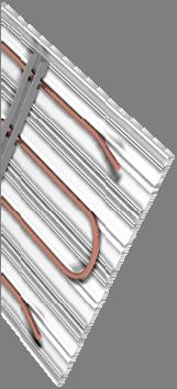


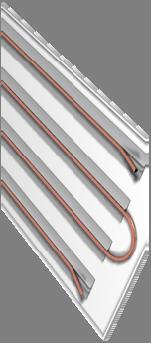

25 Systems Radiant Panels System response o Surface contact of components
26 Systems Radiant Panels Typical Operating Conditions Cooling Heating EWT Dew point + 2 F F Water T 2 6 F F Series or parallel piped Series piped between multiple panels
27 Systems Radiant Panels General Guidance o Heating High heating surface temperatures can be uncomfortable Generally a ceiling surface temperature of max 120 F High surface temperatures acceptable with little occupancy Perimeters Spaced out to prevent a blanketed hot surface Air temperature across panel < panel temperature o Cooling Radiant asymmetry problems rare Maintain surface temperatures above dew point Spread out the load Air temperature across panel > panel temperature
28 Systems Radiant Panels General Guidance o Use operative temperature for thermal comfort Minimize SAT ΔT, or Minimize air volume o Offset variations in surface temperatures Hot/cold walls/ceilings High solar gain o Use panels to activate building mass o Off hour temperature t stabilization ti o Requires 4 6 of clearance o Integrate ceiling components (sprinklers, PA, lighting)


29 Systems Radiant Panels Minimize ventilation Work with operable windows Offset high solar gain Activate building mass


30 Systems Radiant Panels Low ventilation requirement Maintain comfort


31 Systems Passive Beam Purpose: Passive cooling device using natural convection to provide cooling. Dependent ontemperature Dependent on temperature differential between air and water.


32 Systems Passive Beam Background o First installations in 1980s o Concentrated t passive cooling o Displacement ventilation


33 Systems Passive Beam Operation o Warm air pools in ceiling space o Air cools on contact o Cooling is density driven o Velocity related to cooling capacity.
34 Systems Passive Beam Passive beam o 12 x 48 beam in 24 x48 grid ceiling


35 Systems Passive Beam Application o At least ¼ of width above beam for air flow o Free area ½ the area of the beam face o Perimeter applications Offset from the heat source May need to capture the warm current


36 Systems Passive Beam Application o Perforated ceiling Offset spreads out cool air, reduces velocity Metal ceiling cools, acts like radiant panel Free area should be within 20 of beam


37 Systems Passive Beam General Guidance o Allow warm air to rise o Higher temperature t air = higher h capacity o Velocities above 50 fpm at ~250 Btu/hr ft o Avoid locating over heat sources Offset to prevent collisions May chill sedentary occupants o Acts like DV air o Avoid disturbing air flow patterns Move cooled below beam o Maintain cooling without primary air


38 Systems Passive Beam Typical Operating Conditions Cooling Heating EWT Dew point + 2 F n/a Water T 2 6 F n/a Parallel or series piped
39 Systems Passive Beam Passive Beam Performance o Standardized test methods EN o Catalogued based on MWT Tair Relates to Btu/hr ft o Capacity corrections: Skirt height Unit width Free space above unit Return below the unit > 50% free area no correction Free area > 60% for supply no correction Perforation hole size (larger is better)


40 Systems Passive Beam Lower supply air requirement Maintain cooling with high temperature source water


41 Systems Passive Beam Works together with DV to provide cooling Provides cooling minimum i visibility ibilit


42 Systems Active Beam Purpose: Active cooling device using minimal primary air inducing secondary air to provide cooling / heating. Dependent on temperature differential between air and water.


43 Systems Active Beam Background o Original theory with induction units old o Installations ti in 1990s in Europe o Extension of the passive beam
44 Systems Active Beam Operation o Primary air Minimal amounts Forced through nozzles o Secondary air Drawn up through coil o 2 or 4 pipe pp


45 Systems Active Beam Active beam o 12 x 48 beam in 24 x48 grid ceiling
46 Systems Active Beam Application o Typically Btu/hr ft² without t draft o Flexible design o Types 1 way 2 way 4 way o Use thermal plumes for capacity


47 Systems Active Beam Active Beam Performance o Standardized test methods EN ASHRAE in development o Catalogued based on MWT Tair Based on nozzle configuration o Capacity considerations Nozzles Pressure drop Trade off:» Small nozzles = high Btuh/cfm, low Btuh/ft» Large nozzles = low Btuh/cfm, high Btuh/ft Primary air temperature High primary air temperature
48 Systems Active Beam General Guidance o Minimize air, maximize water o Increasing air/ft increases capacity increased induction = increased cooling/heating capacity increased throw = increased P = increased noise o Constant volume typical, VAV possible o Location 12 ceiling Thermal plumes o Temperature control with water o EWT < 140 F o Low height
49 Systems Active Beam General Guidance o Maintenance
 ($) Cleaned if growth found (+$) Connected to a removal")
 o Consider health Biological")
50 Systems Active Beam General Guidance Condensation trays? o Consider ASHRAE 62.1 Inspected for growth min 1x annually (+$) ($) Cleaned if growth found (+$) Connected to a removal system (+$) Field tested or certified slope Coils expected to be wet need MERV6 filter loss of capacity Wet coils attract dust caking and required cleaning (+$) o Consider health Biological growth can lead to health issues
51 Systems Active Beam Typical Operating Conditions Parallel piped Cooling Heating SAT F F Airflow Rate 3 25 cfm/ft EWT Dew point + 2 F F Water ΔT 2 6 F F Water Flow Rate min 0.4 gpm max 2 gpm Water ΔP 0 10 Air ΔP target


52 Systems Active Beam Installation Threaded rod to hangers Speed rail for adjustment Horizontal duct entrance typical


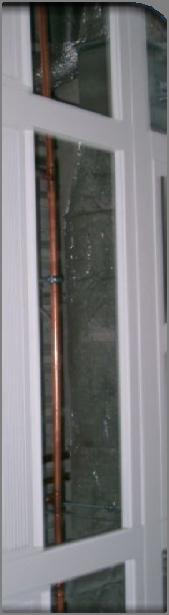
53 Systems Active Beam


54 Systems Active Beam Installation Coil connections Options: Bare Solder, Braze, press on, push on NPT Connection Hard pipe Flex hose
55 Systems Active Beam Design example o 800 ft² open office space o 8 people o Load Sensible 28,000 Btu/hr Latent 1,600 Btu/hr o Design point conditions 75 F db/50% RH (65 gr/lb) Min ventilation (ASHRAE 55) = 88 cfm
56 Systems Active Beam Design example o Latent load: Supply air RTU: 55 F db/53.5 F wb; w = 58.7 gr/lb DOAS w/heat recovery: 58 F db/54 F wb; w = 55.9 gr/lb 1,600 = 0.68 x cfm x (65 w) RTU: at w = 58.7 gr/lb, cfm = 373 DOAS: at w = 55.9 gr/lb, cfm = 258
57 Systems Active Beam Design example o Roughing in the beams: Useanexample example beam, noprimary aircooling 8 beam Troom = 75 F SAT = 75 F EWT = dp + 2 F = 57 F Water flow rate = 1.5 gpm ΔP air = 0.5 Nozzle cfm Coil Btu/hr config A B C D E
58 Systems Active Beam Design example o Roughing in the beams: Add air side cooling 55 F db Get total Btu/hr Nozzle cfm Coil Btu/hr Air Btu/hr Total Btu/hr config A B C D E
59 Systems Active Beam Design example o Roughing in the beams: Find capacity per cfm and per length Nozzle cfm Total Btu/hr Btuh/cfm Btuh/ft config A B C D E
60 Systems Active Beam Design example o Roughing in the beams: Convert to total cfm and length using load 28,000 Btu/hr Nozzle Btuh/cfm Btuh/ft Total CFM Total Length config A B C D E
61 Systems Active Beam Design example o Roughing in the beams: Compare to original min cfm Std RTU: min cfm = 373 Nozzle config cfm Total Btu/hr Btuh/cfm Btuh/ft Total CFM Total Length A B C D E
62 Systems Active Beam Design example o Roughing in the beams: Compare to original min cfm DOAS w/ heat recovery (higher primary air temp)» min cfm = 258 Nozzle config cfm Total Btu/hr Btuh/cfm Btuh/ft Total CFM Total Length A B C D E

63 Systems Active Beam Design example o Compare and decide


64 Systems Active Beam Operates as linear slot diffuser Integrates with tile grid, drywall
65 Systems Active Beam 1 way throw Located at bulkhead


66 Systems Chilled Sail Purpose: Passive cooling device combined radiant and convective cooling Cross between radiant panel Cross between radiant panel and passive beam.


67 Systems Chilled Sail Background o Installations from late 1990 o Blend of radiant and convection More cooling Reduce draft risk


68 Systems Chilled Sail Operation o Warm air contacts cool elements o Surface temperature activated for radiant exchange

69 Systems Chilled Sail Chilled sail o 24 x 48 exposed sail
70 Systems Chilled Sail Application o Combined with other ventilation sources o Flexible design o Types Exposed Concealed o Increases total cooling capacity in area
71 Systems Chilled Sail General Guidance o Minimize air, maximize water o Takes advantage of operative temperature o Active building mass o Locate over occupants o Higher surrounding temperatures increase convection o Ventilation Works best with DV Blow O/H cool air elsewhere o Heating is application specific o > 60% of ceiling space reduces capacity
72 Systems Chilled Sail Typical Operating Conditions Cooling Heating EWT Dew point + 2 F Application specific Water T 2 6 F Application specific Parallel or series piped
73 Systems Chilled Sail Design Example o Single occupant office 10 x10 Exposed ceiling deck, sails at 9 Latent load = 220 Btu/hr Sensible load = 3,500 Btu/hr Min ventilation = 20 cfm SAT = 45 F db/45 F wb (w = 44.3 gr/lb) Troom = 77 F db/63.6 F wb (w = 67.1 gr/lb, dp = 56 F) Toperative = 75 F EWT = 58 F
74 Systems Chilled Sail Design Example o Sail capacity = 50.7 Btu/hr ft² Troom = 77 F EWT = 58 F o Air sensible capacity Q = 108x 1.08 cfm x ΔT = 108x x (77 45) = 691 Btu/hr o Air latent capacity Q = 0.68 x cfm x Δw = 0.68 x 20 x ( ) = 310 Btu/hr o DP < EWT o Remaining sensible load 3, = 2809 Btu/hr At 50.7 Btu/hr ft² f² = 55 ft² f² Use 2.5 x 8 (60 ft²)


75 Systems Chilled Sail Classroom environment with operable windows Maintain comfort with minimum air


76 Systems Chilled Sail High radiant exchange with ceiling sail Displacement ventilation air supply
77 Review of technology Comparison of technologies Based on common operating conditions Cooling Up to 30 Btuh/ft² Panels Sails Passive Beam Btuh/ft² Btuh/ft Active Beam Btu/ft Heating > 90 Btuh/ft² Application None specific Btu/ft Ventilation None None None Integrated
78 Review of technology Review of applications Panel Sail Passive beam Active Beam Office good good good good Laboratory good good good good* Classroom Fair good good fair Renovation good* good* good* good* Healthcare good???
79 Systems design Low grade energy sources Cooling water Ground source heat pump Zone to zone heat pump Dehumidification leaving water Heating Water Ground source heat pump Condensing boiler Solar Economizer Evaporative Cooling Open pond
80 Systems Design Costing Comparisons Variations from average design Higher Piping Valving Hydronic components Additional chiller (?) Cooling/heating technology (?) Lower Ducting Fan and dehumidification equip. Plenum depth (fl. to fl. height) Support infrastructure Riser/mechanical space Chiller operating cost low grade energy usage Annual maintenance Architectural ceiling (visible sail)

81 System Design Piping shared chiller


82 System Design Piping staging tank
83 System Design Piping supply and control


84 System Design Ducting
85 System Design Commissioning o Water flow rates o Nozzle configuration (active beam) o Plenum pressure = cfm (active beam)


86 QUESTIONS?
Chilled Beams. The new system of choice?
 Chilled Beams The new system of choice? Presented By: Kevin M. Pope P.E. Jason Leffingwell Hammel Green And Abrahamson, Inc. and Ken Bauer, P.E., LEED AP Butters-Fetting Co., Inc. History of Chilled Beams
Ceiling Radiant Cooling Panels
 2006, American Society of Heating, Refrigerating and Air-Conditioning Engineers, Inc (wwwashraeorg) Published in ASHE Journal Vol 48, Oct 2006 For personal use only Additional reproduction, distribution,
DISPLACEMENT VENTILATION
 DISPLACEMENT VENTILATION D3 OVERVIEW The fundamental approach to displacement ventilation utilizes the natural buoyancy forces created by the convective flows from heat sources in the space. As supply
ACBC Floor Mounted Active Beam
 Floor Mounted Active Beam The Price Floor Mounted Active Beam,, is designed for occupant comfort. It provides high cooling and heating capacities while simultaneously supplying ventilation air from a DOAS
ANSI/ASHRAE STANDARD , METHODS OF TESTING CHILLED BEAMS
 ANSI/ASHRAE STANDARD 200-2015, METHODS OF TESTING CHILLED BEAMS NEMIC 2017 Agenda 1. Foreword 2. Purpose & Scope 3. Definitions 4. Instrumentation & Facilities 5. Test Methods 6. Reporting 7. Normative
ACBC Floor Mounted Active Beam
 Floor Mounted Active Beam The Price Floor Mounted Active Beam,, is designed for occupant comfort. It provides high cooling and heating capacities while simultaneously supplying ventilation air from a DOAS
Beam? previous. 50% over our. to our. the competition. reducing. first cost of the. project. shown at same. water flow
 Why Specify the SEMCO IQHC Active Chilled Beam? Features and Benefits Provided Byy the SEMCO IQHC Active Chilled Beam Reason #1: The Highest Cooling and/or Heating Capacity Output Available The SEMCO IQHC
BUILDING DESIGN FOR HOT AND HUMID CLIMATES IMPLICATIONS ON THERMAL COMFORT AND ENERGY EFFICIENCY. Dr Mirek Piechowski 1, Adrian Rowe 1
 BUILDING DESIGN FOR HOT AND HUMID CLIMATES IMPLICATIONS ON THERMAL COMFORT AND ENERGY EFFICIENCY Dr Mirek Piechowski 1, Adrian Rowe 1 Meinhardt Building Science Group, Meinhardt Australia 1 Level 12, 501
Underf loor For Schools
 The following article was published in ASHRAE Journal, May 2008. Copyright 2008 American Society of Heating, Refrigerating and Air-Conditioning Engineers, Inc. It is presented for educational purposes
Optimizing Indoor Environments for Occupant Satisfaction. Presented by: Kelli Goldstone April 2016
 Optimizing Indoor Environments for Occupant Satisfaction Presented by: Kelli Goldstone April 2016 Outline Function of HVAC Thermal Comfort Air Distribution Radiant Heating / Cooling Case Study Function
The Creative and Performing Arts High School (CAPA) Pittsburgh, PA 9/30/2002 Andrew Tech Mechanical Option Prof. S. A. Mumma
 Pittsburgh, PA 9/30/2002 Andrew Tech Mechanical Option Prof. S. A. Mumma") LEED Green Building Certification The purpose of the LEED Green Building Rating is to provide a national standard that aims to improve environmental, health and economic performance of buildings using
LEED Green Building Certification The purpose of the LEED Green Building Rating is to provide a national standard that aims to improve environmental, health and economic performance of buildings using
Application of Advanced Energy Technologies
 GLOBALCON 2002 Philadelphia, Pennsylvania March 27, 2002 Application of Advanced Energy Technologies Michael K. West, Ph.D., P.E. Building Systems Scientist Advantek Consulting, Inc. www.advantekinc.com
Radiant Slab Cooling for Retail
 This article was published in ASHRAE Journal, December 2010. Copyright 2010 American Society of Heating, Refrigerating and Air-Conditioning Engineers, Inc. Reprinted here by permission from ASHRAE at www.newportventures.net.
How to Reduce Energy Use in Your Labs by Up to 50%
 How to Reduce Energy Use in Your Labs by Up to 50% Illinois Chapter of ASHRAE April 11, 2017 Dan Doyle, Chairman Grumman/Butkus Associates 1 Course Description Labs have high exhaust requirements and large
Hourly Analysis Program v.4.1 Page 1 of 1
 Air System Design Load Summary for Zona 11 DESIGN COOLING DESIGN HEATING COOLING DATA AT Dec 1700 HEATING DATA AT DES HTG COOLING OA DB / WB 33.1 C / 23.5 C HEATING OA DB / WB -0.6 C / -3.2 C Sensible
Fundamentals of Test & Balance for Engineers, Cx & Energy Providers Course Number: CXENERGY1619
 AABC Commissioning Group AIA Provider Number 50111116 Fundamentals of Test & Balance for Engineers, Cx & Energy Providers Course Number: CXENERGY1619 Jim Hall, PE, TBE, CxA Systems Management & Balancing,
Field Accuracy of Temperature Measurements in TAB Work Andrew P. Nolfo, PE
 Field Accuracy of Temperature Measurements in TAB Work Andrew P. Nolfo, PE The purpose of this article is to discuss the measuring and reporting of temperatures at heat transfer equipment during the Testing
David H. Koch Institute for Integrative Cancer Research Senior Capstone Mechanical Option. Proposal
 0 David H. Koch Institute for Integrative Cancer Research Senior Capstone Mechanical Option Proposal David H. Koch Institute for Integrative Cancer Research Massachusetts Institute of Technology Cambridge,
Large University Central Chiller Plant Design Considerations
 Carrier Engineering Newsletter Volume 5, Issue 3 Large University Central Chiller Plant Design Considerations Large campus chilled water plants have unique constraints and need careful evaluation for successful
DEVELOPMENT AND CONSTRUCTION OF BIOCLIMATIC DOUBLE SKIN ACTIVE FACADE FOR HOT AND HUMID CLIMATE OF UAE
 DEVELOPMENT AND CONSTRUCTION OF BIOCLIMATIC DOUBLE SKIN ACTIVE FACADE FOR HOT AND HUMID CLIMATE OF UAE Eng. Ray Karbor MSc. Director Engenius Green Technology FZE RAK, UAE & Ex-Sustainability Manager Reem
Designing Air-Distribution Systems To Maximize Comfort
 Designing Air-Distribution Systems To Maximize Comfort By David A. John, P.E., Member ASHRAE An air-distribution system that provides occupant thermal comfort can be a complicated system to predict and
LindabPlexus. Supply air beam. lindab we simplify construction
 Lindab 11.2017 Lindab Ventilation. All forms of reproduction without written permission are forbidden. is the registered trademark of Lindab AB. Lindab's products, systems, product and product group designations
Hourly Analysis Program v.4.1 Page 1 of 1
 Air System Design Load Summary for Zona 8 DESIGN COOLING DESIGN HEATING COOLING DATA AT Dec 1700 HEATING DATA AT DES HTG COOLING OA DB / WB 33.1 C / 23.5 C HEATING OA DB / WB -0.6 C / -3.2 C Sensible Latent
Planning for Biomed Facility Puts Energy Efficiency Under Microscope
 Planning for Biomed Facility Puts Energy Efficiency Under Microscope Chilled beams, runaround-loop ERV system included May 19, 2014 By DAN VASTYAN, Common Ground, Manheim, Pa. HPAC Engineering Constructing
LindabCarat. Chilled beam. lindab we simplify construction
 lindab we simplify construction Lindab 08.2016 Lindab Ventilation. All forms of reproduction without written permission are forbidden. is the registered trademark of Lindab AB. Lindab's products, systems,
OPERATION AND CONTROL OF THERMALLY ACTIVATED SLAB HEATING AND COOLING SYSTEMS
 OPERATION AND CONTROL OF THERMALLY ACTIVATED SLAB HEATING AND COOLING SYSTEMS Bjarne W. Olesen Ph. D, International Centre for Indoor Environment and Energy, Department of Mechanical Engineering, Technical
Measuring Up. Tools for High Performance Building Performance. RESNET 2008 San Diego, CA February 20, 2008 Bill Spohn. Bill Spohn, testo, inc.
 Measuring Up Tools for High Performance Building Performance RESNET 2008 San Diego, CA February 20, 2008 Bill Spohn Measuring up Building performance evaluation Observation and measurements. Principles
Retro-Commissioning for Existing Facilities
 Retro-Commissioning for Existing Facilities Tom Meyer Director, Technical Programs National Environmental Balancing Bureau 8575 Grovemont Circle Gaithersburg, Maryland 20877 (301) 977-3698 www.nebb.org
ABSTRACT I. INTRODUCTION II. METHODS AND MATERIAL
 2017 IJSRSET Volume 3 Issue 2 Print ISSN: 2395-1990 Online ISSN : 2394-4099 Themed Section: Engineering and Technology Chiller and AHU Design for A commercial Usage S M Azfar Hashmi, Mirza Muneer Baig,
Walter Reed National Military Medical Center Bethesda, MD
 Walter Reed National Military Medical Center Bethesda, MD Technical Report Three: Mechanical Systems Existing Conditions Evaluation Prepared For: Dr. James D. Freihaut Prepared By: Justin Herzing Date:
COMFORT-PRODUCTIVITY Building costs COMFORT-PERFORMANCE. Radiant Heating and Cooling Systems for Better Comfort and Energy Efficiency INDOOR - OUTDOOR
 Radiant Heating and Cooling Systems for Better Comfort and Energy Efficiency Professor Bjarne W. Olesen, PhD Director International Centre for Indoor Environment and Energy Department of Civil Engineering
Development of New Self-Comparison Test Suites for EnergyPlus
 Development of New Self-Comparison Test Suites for EnergyPlus Michael J. Witte Robert H. Henninger GARD Analytics, Inc., Arlington Hts., IL Drury B. Crawley U.S. Department of Energy, Washington, DC IBPSA-USA
Thermal Delight in Architecture
 THERMAL COMFORT DESIGN CRITERIA Ball State Architecture ENVIRONMENTAL SYSTEMS 1 Grondzik 1 Thermal Delight in Architecture This work began with the hypothesis that the thermal function of a building could
Thesis Proposal. Park. Findlay 12/10/2010. Connor Blood
 1 Park Place Corporate Center One Mechanical Senior Thesis Project Thesis Proposal Park Place Corporate Center One Findlay Township,, PA 12/10/2010 Proposal Connor Blood 2 Park Place Corporate Center One
COMMERCIAL LOAD ESTIMATING. Load Estimating Level 3: Block and Zone Loads. Technical Development Program
 COMMERCIAL LOAD ESTIMATING Load Estimating Level 3: Block and Zone Loads Technical Development Program Technical Development Programs (TDP) are modules of technical training on HVAC theory, system design,
Thermal Delight in Architecture
 THERMAL COMFORT OPR Ball State Architecture ENVIRONMENTAL SYSTEMS 1 Grondzik 1 Thermal Delight in Architecture This work began with the hypothesis that the thermal function of a building could be used
Senior Design Project for UNO. Design of the International Studies Building: An Environmental Analysis
 Senior Design Project for UNO Design of the International Studies Building: An Environmental Analysis Design Intent Implement Passive & Active design strategies in order to make the building: More Energy
Valent Packaged Rooftop Units A Fresh Choice for High-Percentage Outdoor Air Designs. Valent is a business of Unison Comfort Technologies.
 Valent Packaged Rooftop Units A Fresh Choice for High-Percentage Outdoor Air Designs Valent is a business of Unison Comfort Technologies. When your HVAC system design calls for high-percentage or 100%
Energy modeling in IDA ICE according to ASHRAE , app. G
 Energy modeling in IDA ICE according to ASHRAE 90.1-2007, app. G About this document This document is a user s guide for a relatively experienced IDA ICE operator for using the 90.1 add-in and for performing
Chilled Water Plant Redesign
 17 Chilled Water Plant Redesign OVERVIEW The chilled water plant redesign includes the addition of a thermal energy storage system. This allows for economic and operational benefits for the facility by
Sub Wet-Bulb Evaporative Chiller
 Emerging Technologies Sub Wet-Bulb Evaporative Chiller Prepared by: Emerging Products Customer Service Southern California Edison June 2015 Acknowledgments Southern California Edison s Emerging Products
Texas Hospital. Central Plant Redesign. Central Utility Plant SECOND PLACE HEALTH CARE FACILITIES, EXISTING 2013 ASHRAE TECHNOLOGY AWARD CASE STUDIES
 This article was published in ASHRAE Journal, January 2014. Copyright 2014 ASHRAE. Posted at www. ashrae.org. This article may not be copied and/or distributed electronically or in paper form without permission
McCarran International Airport Terminal 3
 McCarran International Airport Terminal 3 The Pennsylvania State University Architectural Engineering Senior Thesis Final Report Evaluation of Underfloor Air Distribution and Displacement Ventilation Systems
NEWMOA June 30, Fran Boucher LEED AP, Certified Energy Manager Senior Energy Engineer
 NEWMOA June 30, 2009 Fran Boucher LEED AP, Certified Energy Manager Senior Energy Engineer Utility Incentives MA, RI, NH, VT, ME, CT, Long Island NY, Gas in NYC New construction and gas in Upstate NY.
Asset Energy Calculator Guidance
 Asset Energy Calculator Guidance Introduction This section has been produced to give BREEAM In-Use assessors further guidance on the workings of the asset energy calculator so it is clear how any improvements
LEED Commissioning and Actual Energy Use. John Kokko, P.Eng. LEED A.P. Vice President Enermodal Engineering
 LEED Commissioning and Actual Energy Use John Kokko, P.Eng. LEED A.P. Vice President Enermodal Engineering AIA Quality Assurance Learning Objectives 1. Why Best Practice and Fundamental Commissioning are
DEMAND CONTROLLED VENTILATION (DCV) SYSTEMS
 SYSTEMS") DEMAND CONTROLLED VENTILATION (DCV) SYSTEMS Mari-Liis Maripuu, PhD CIT Energy mari-liis.maripuu@cit.chalmers.se Swegon Air Academy, Portugal, 27 May 211 Outline Introduction Concept of a DCV system Adapting
DEMAND CONTROLLED VENTILATION (DCV) SYSTEMS Mari-Liis Maripuu, PhD CIT Energy mari-liis.maripuu@cit.chalmers.se Swegon Air Academy, Portugal, 27 May 211 Outline Introduction Concept of a DCV system Adapting
MEP's Letter of Assurance
 MEP's Letter of Assurance Instructions Multifamily Residential WELL Certification is determined by onsite Performance Verification and documentation, including Letters of Assurance from the appropriate
HVAC System Analysis and Energy Audit: The Providence Athenaeum
 Roger Williams University DOCS@RWU Engineering and Construction Management Community Partnerships Center 2014 HVAC System Analysis and Energy Audit: The Providence Athenaeum Nicholas Farland Trevor Larson
Principles of Ventilation and Air Conditioning Design & Installation
 Unit 10: Unit code Principles of Ventilation and Air Conditioning Design & Installation D/615/1926 Unit level 4 Credit value 15 Introduction The demands of modern living as well as the potential impact
Air Conditioning Inspections for Buildings Assessing Equipment Sizing
 Air Conditioning Inspections for Buildings Assessing Equipment Sizing PRESENTED BY NIRAJ MISTRY aircon@stroma.com Size V s Load Regulation 22 of EPB Regulations The inspection report must include an assessment
Indoor Climate and Ventilation in Finnish Schools Air Distribution and Temperature Control in Classrooms
 Indoor Climate and Ventilation in Finnish Schools Air Distribution and Temperature Control in Classrooms Abstract Finland is a country without a debate on natural ventilation. In such a cold climate, it
Zero Carbon Building Energy Modelling Guidelines. October 31, 2017
 Zero Carbon Building Energy Modelling Guidelines October 31, 2017 Contents 1. INTRODUCTION... 3 1.1 DEFINITIONS... 4 2. CALCULATING TEDI... 5 2.1 INTERNAL HEAT GAINS... 6 2.2 CALCULATING BUILDING ENVELOPE
Air Source Heat Pumps in the Commercial Market. Thursday, February 5, :00-10:30 a.m.
 Air Source Heat Pumps in the Commercial Market Thursday, February 5, 2015 9:00-10:30 a.m. 1. Commercial Equipment Applications, Benefits, Limitations 2. Case Studies 3. Efficiency Vermont Technical & Financial
Mechanical Product Overview
 Mechanical Product Overview The founding principles of Price have never changed business integrity, first class service, innovation and a commitment to people. PURPOSE BUILT FOR YOUR APPLICATION Whether
Doubling Down on Not Balancing Variable Flow Hydronic Systems BY STEVEN T. TAYLOR, P.E., FELLOW ASHRAE
 This article was published in ASHRAE Journal, December 2017. Copyright 2017 ASHRAE. Posted at www.ashrae.org. This article may not be copied and/or distributed electronically or in paper form without permission
IECC Commercial Significant Changes Summary Tier I
 2009-2015 IECC Commercial Significant Changes Summary Tier I The first change is in the layout of the book. Instead of having Chapters 1-3 that applied to all projects and then having Chapter 4 Residential
Energy Trigger (A Existing Building Upgrade Mechanism Model)
") Trigger (A-11.2.1.2 Existing Building Upgrade Mechanism Model) Applicability All Building Permit applications for projects related to existing buildings are required to follow the energy upgrade trigger
Trigger (A-11.2.1.2 Existing Building Upgrade Mechanism Model) Applicability All Building Permit applications for projects related to existing buildings are required to follow the energy upgrade trigger
Canada Published online: 28 Feb 2011.
 This article was downloaded by: [Bibliothèque ÉTS] On: 21 July 2015, At: 04:30 Publisher: Taylor & Francis Informa Ltd Registered in England and Wales Registered Number: 1072954 Registered office: 5 Howick
Sproul Hall Cooling Load Reduction
 U N I V E R S I T Y O F C A L I F O R N I A, D A V I S BERKELEY DAVIS IRVINE LOS ANGELES MERCED RIVERSIDE SAN DIEGO SAN FRANCISCO SANTA BARBARA SANTA CRUZ Sproul Hall Cooling Load Reduction Alex Nichols,
Achieving acoustical standards in the classroom Study of HVAC systems and classroom acoustics
 Achieving acoustical standards in the classroom Study of HVAC systems and classroom acoustics Trane believes the facts and suggestions presented here to be accurate. However, final design and application
Application of a cooling tower model for optimizing energy use
 Advances in Fluid Mechanics X 305 Application of a cooling tower model for optimizing energy use G. C. O Mary & D. F. Dyer Department of Mechanical Engineering, Auburn University, USA Abstract The overall
CERTIFICATE OF FIELD VERIFICATION & DIAGNOSTIC TESTING (Page 1 of 8)
") CERTIFICATE OF FIELD VERIFICATION & DIAGNOSTIC TESTING (Page 1 of 8) Builder or Installer Name Builder or Installer Contact Telephone Plan/Permit (Additions or Alterations) Number Compliance Method (Prescriptive)
CERTIFICATE OF FIELD VERIFICATION & DIAGNOSTIC TESTING (Page 1 of 8) Builder or Installer Name Builder or Installer Contact Telephone Plan/Permit (Additions or Alterations) Number Compliance Method (Prescriptive)
Assessor Name: Membership number: Reference: Level of assessment: L3 L4 New Post code:
 Project /Survey Details Address: Assessor Name: Membership number: Reference: Level of assessment: L3 L4 New Post code: Building Age: Weather : Conservation status: Building plans available: Yes No Date
COOLING TOWER DESIGN FOR CENTRAL GENERATORS OF CUET, BANGLADESH. Mohammad Sharif Khan, Golam Mainuddin, Abu Sadat Mohammad Sayem, Nadeem Nafis
 Proceedings of the 4 th BSME-ASME International Conference on Thermal Engineering 7-9 December, 008, Dhaka, Bangladesh COOLING TOWER DESIGN FOR CENTRAL GENERATORS OF CUET, BANGLADESH. Mohammad Sharif Khan,
UC Berkeley HVAC Systems
 UC Berkeley HVAC Systems Title Simplified calculation method for design cooling loads in underfloor air distribution (UFAD) systems Permalink https://escholarship.org/uc/item/5w53c7kr Authors Schiavon,
Condenser Water Heat Recovery"
 PLEASE MUTE CELL PHONES Condenser Water Heat Recovery" Julian de Bullet ASHRAE Distinguished Lecturer Director of Industry Relations McQuay International 703-395-5054 1 What Is Sustainability? sustainable
Ventilation for Changeover-Bypass VAV Systems
 Copyright 2004, American Society of Heating, Refrigerating and Air-Conditioning Engineers, Inc. This posting is by permission of ASHRAE Journal. This article may not be copied nor distributed in either
TAB (test-adjustbalance) in the Sustainable Environment & Lessons Learned. HVAC Excellence Conference & Training March 17-18, 2013 Tom Hanlon
 in the Sustainable Environment & Lessons Learned. HVAC Excellence Conference & Training March 17-18, 2013 Tom Hanlon") TAB (test-adjustbalance) in the Sustainable Environment & Lessons Learned HVAC Excellence Conference & Training March 17-18, 2013 Tom Hanlon Outline: Sustainable Environment?? LEED V3 Green Globes ASHRAE
TAB (test-adjustbalance) in the Sustainable Environment & Lessons Learned HVAC Excellence Conference & Training March 17-18, 2013 Tom Hanlon Outline: Sustainable Environment?? LEED V3 Green Globes ASHRAE
White Paper ENVELOPE-FIRST APPROACH TO NET-ZERO ENERGY BUILDINGS
 BOULDER CHICAGO NASHVILLE SALT LAKE CITY SAN FRANCISCO SPRINGFIELD, MO WASHINGTON, DC 2540 Frontier Avenue, Suite 100 Boulder, Colorado 80301 303.444.4149 White Paper ENVELOPE-FIRST APPROACH TO NET-ZERO
ENGINEERING UPDATE WHITE PAPER: BUILDING PERFORMANCE METRICS. price-hvac.com. May 2013 Vol. 10
 ENGINEERING UPDATE May 2013 Vol. 10 WHITE PAPER: BUILDING PERFORMANCE METRICS By Hugh Crowther P. Eng. Executive Vice President, Product Management and Technology There is a steady and determined march
SECTION COOLING TOWER
 PART 1 GENERAL 1.1 SECTION INCLUDES A. Mechanical induced draft Cooling Tower B. Controls C. Ladder and handrails 1.2 REFERENCES SECTION 23 65 00 COOLING TOWER A. ANSI/AFBMA 9 - Load Rating and Fatigue
MEP's Letter of Assurance
 MEP's Letter of Assurance Instructions WELL Certification is determined by onsite Performance Verification and documentation, including Letters of Assurance from the appropriate professionals overseeing
Performance evaluation of a small-scale polygeneration plant including a desiccant cooling system and an innovative natural gas ICE
 Performance evaluation of a small-scale polygeneration plant including a desiccant cooling system and an innovative natural gas ICE Armando Portoraro Energetics Department Politecnico di Torino (Italy)
Ventilative Cooling potential tool
 Ventilative Cooling potential tool User guide Version 1.0 IEA EBC Programme Annex 62 Ventilative Cooling AUTHORS: ANNAMARIA BELLERI EURAC RESEARCH Institute for renewable energy Druso 1 39100 Bolzano Italy
B. System Design and Performance Requirements
 15625 Water Chillers This document provides design standards only, and is not intended for use, in whole or in part, as a specification. Do not copy this information verbatim in specifications or in notes
An experimental investigation of a passive chilled beam system in subtropical
 An experimental inestigation of a passie chilled beam system in subtropical conditions Alex Hole 1, Risto Kosonen 2 1 Arup, Sydney - Australia 2 Halton, Kausala - Finland Corresponding email: alex.hole@arup.com.au
This session is approved for 0.2 IACET or 1.5 PDH. Many states accept this for Professional Continuing Education.
 Important! This session is approved for 0.2 IACET or 1.5 PDH. Many states accept this for Professional Continuing Education. To qualify for credit you must: Be sure your badge was scanned when you entered
125BEPM - Building energy performance modeling. Lecture handouts
 125BEPM - Building energy performance modeling Lecture handouts 2 - Introduction to building energy performance modeling and simulation prof. Karel Kabele - Page 1/13 - CONTENT 1 INTRODUCTION TO BUILDING
EADQUARTERS. Final Thesis Report. Stephanie Kunkel Mechanical Option
 EADQUARTERS 707 N. Calvert St. Final Thesis Report AE Senior Thesis Spring 2011 Stephanie Kunkel www.engr.psu.edu/ae/thesis/portfolios/2011/slk5061 Mechanical Option Dr. Bahnfleth April 7, 2011 K U N K
Model Based Building Chilled Water Loop Delta-T Fault Diagnosis
 Model Based Building Chilled Water Loop Delta-T Fault Diagnosis Lei Wang, Ph.D., P.E. James Watt, P.E. Juan Zhao, Ph.D., P.E Energy Systems Laboratory, Texas A&M University College Station, Texas Abstract
Industrial Retrofit Guide. Superior Solutions for Industrial Heating and Ventilating
 Industrial Retrofit Guide Superior Solutions for Industrial Heating and Ventilating CONTENTS 4 Recognizing the Complexity of Industrial HVAC, Process Manufacturing, and Process Requirements 6 Why Dedicated
DESIGN OF A GREEN DEMO BUILDING IN A HOT AND HUMID CITY IN CHINA. Ana Bacall Sebesta Blomberg & Associates Woburn, MA
 DESIGN OF A GREEN DEMO BUILDING IN A HOT AND HUMID CITY IN CHINA Yi Jiang Sebesta Blomberg & Associates Woburn, MA William Hammer HKT Architects Somerville, MA Ana Bacall Sebesta Blomberg & Associates
Italcementi Center for Research and Innovation
 Italcementi Center for Research and Innovation Bergamo, Italy LEED-NC v2.1 EAc1 A. Project Narrative (Viridian) analyzed the energy use of the proposed Italcementi Center for Research and Innovation located
Optimisation of an HVAC system for energy saving and thermal comfort in a university classroom
 Optimisation of an HVAC system for energy saving and thermal comfort in a university classroom Giovanni Semprini DIN / CIRI, University of Bologna, Bologna, Italy Cosimo Marinosci DIN / CIRI, University
Design and development of a residential gas-fired heat pump
 Design and development of a residential gas-fired heat pump Edward A Vineyard a*, Ahmad Abu-Heiba a, Isaac Mahderekal b a Oak Ridge National Laboratory, P.O. Box 2008, MS 6070, Oak Ridge, TN, 37831, USA
Proceedings of BS2015: 14th Conference of International Building Performance Simulation Association, Hyderabad, India, Dec. 7-9, 2015.
 OPTIMISATION OF SUPPLY AIR TEMPERATURE CONTROLS FOR VAV SYSTEMS IN TEMPERATE AUSTRALIA Paul Bannister, Hongsen Zhang Energy Action (Australia) Pty Ltd, Canberra, Australia Paul.Bannister@energyaction.com.au;
TO MEASURE NOT MODEL:
 BIG TEN & FRIENDS Mechanical & Energy Conference College Park, Maryland September 20 23, 2015 TO MEASURE NOT MODEL: Case Study Purdue University Center for High Performance Design at the Ray W. Herrick
 Baffled Openings at Chain Link Fencing: Design shall consist of two end-posts set 4 feet apart, and a 10 foot wide chain-link fence panel equal in height as the adjacent fence. Chain link fence panel shall
Optimization of air tightness and night ventilation for Passive houses in Italian climates under Fanger and Adaptive comfort models
 L. Pagliano et al, I: Optimization of air tightness and night ventilation for Passive houses in Italian climates... 1 Optimization of air tightness and night ventilation for Passive houses in Italian climates
Ground-Coupled Heat Pump And Energy Storage
 Ground-Coupled Heat Pump And Energy Storage By Ed Lohrenz, Member ASHRAE; and Sergio Almeida, P.Eng., Member ASHRAE Ground-coupled heat pump (GCHP) systems consume less purchased energy than an HVAC system
Hotels: Water and Energy
 Hotels: Water and Energy Agenda 01 Introduction 05 Hotel System Options 02 Company Overview 06 Hotel Energy Conservation 03 Hotel Energy & Water Use 07 Hotel Project Examples 04 Design Philosophy Introduction
YORK UNITIZED ENERGY RECOVERY VENTILATOR (ERV) Superior air-flow 300 6,200 CFM
 Superior air-flow 300 6,200 CFM") YORK UNITIZED ENERGY RECOVERY VENTILATOR (ERV) Superior air-flow 300 6,200 CFM YORK UNITIZED ENERGY RECOVERY VENTILATORS Regardless of building type or rating system, today s building must be as energy
YORK UNITIZED ENERGY RECOVERY VENTILATOR (ERV) Superior air-flow 300 6,200 CFM YORK UNITIZED ENERGY RECOVERY VENTILATORS Regardless of building type or rating system, today s building must be as energy
Thermal performance of a closed wet cooling tower for chilled ceilings: measurement and CFD simulation
 INTERNATIONAL JOURNAL OF ENERGY RESEARCH Int. J. Energy Res. 2000; 24:1171}1179 Thermal performance of a closed wet cooling tower for chilled ceilings: measurement and CFD simulation Sa!a Ri!at*, Armando
2010 Standard for Performance Rating of Variable Refrigerant Flow (VRF) Multi-Split Air-Conditioning and Heat Pump Equipment
 Multi-Split Air-Conditioning and Heat Pump Equipment") ANSI/AHRI Standard 1230 with Addendum 2 2010 Standard for Performance Rating of Variable Refrigerant Flow (VRF) Multi-Split Air-Conditioning and Heat Pump Equipment Approved by ANSI on 2 August 2010 ANSI/AHRI
ANSI/AHRI Standard 1230 with Addendum 2 2010 Standard for Performance Rating of Variable Refrigerant Flow (VRF) Multi-Split Air-Conditioning and Heat Pump Equipment Approved by ANSI on 2 August 2010 ANSI/AHRI
The Art of Thermal Mass Modeling for Energy Conservation in Buildings, Part 2
 The Art of Thermal Mass Modeling for Energy Conservation in Buildings, Part 2 Linda Lam is a Project Engineer at Transsolar, Inc. She has a traditional mechanical engineering background with an energetic
FACILITY DESIGN PLAN FOR HARDING HALL RENOVATION AND ADDITION SOUTH DAKOTA STATE UNIVERSITY DATE: March 29, 2017
 FACILITY DESIGN PLAN FOR HARDING HALL RENOVATION AND ADDITION SOUTH DAKOTA STATE UNIVERSITY DATE: March 29, 2017 SDSU requests approval of this Facility Design Plan for renovation and addition to Harding
ERT 318/4 UNIT OPERATIONS SEMESTER 1 (2013/2014)
") ERT 318/4 UNIT OPERATIONS SEMESTER 1 (2013/2014) WATER COOLING TOWER School of Bioprocess Engineering University Malaysia Perlis EXPERIMENT Water Cooling Tower 1.0 OBJECTIVES 1.1 To determine energy and
ERT 318/4 UNIT OPERATIONS SEMESTER 1 (2013/2014) WATER COOLING TOWER School of Bioprocess Engineering University Malaysia Perlis EXPERIMENT Water Cooling Tower 1.0 OBJECTIVES 1.1 To determine energy and
5. AMCA 301 Method of Publishing Sound Ratings for Air Moving Devices. 6. AMCA 500 Test Methods for Louver, Dampers, and Shutters
 PART 1: GENERAL 1.01 Purpose: A. This standard is intended to provide useful information to the Professional Service Provider (PSP) to establish a basis of design. The responsibility of the engineer is
Green Building Guideline of Jordan
 Green Building Guideline of Jordan T. Awadallah 1*, S. Habet 1, A. Mahasneh 1, H. Adas 2 1 Royal Scintific Society, Amman, Jordan 2 National Energy Research Center, Amman, Jordan * Corresponding author.