CHAPTER 1. GENERAL PROVISIONS
|
|
|
- Robert Boyd
- 6 years ago
- Views:
Transcription
1 Table of Contents CHAPTER 1. GENERAL PROVISIONS 1.0 Introduction Enactment Authority Jurisdiction Purpose Amendments and Revisions Table 1-1 Examples of Minor and Major Revisions Enforcement Responsibility Review and Approval Interpretation Relationship to Other Standards Variances from these Criteria Acronyms CHAPTER 2. STORMWATER MANAGEMENT POLICY & PRINCIPLES 2.0 Introduction Principles Planning Policy Design Policy Operations and Maintenance Policy Construction of Public Improvements Policy Floodplain Policy Regulatory/Legal Policy Hazard Minimization & Public Safety Policy Miscellaneous Policy CHAPTER 3. STORMWATER MANAGEMENT AND DEVELOPMENT 3.0 Introduction Planning for Stormwater Management Impacts of Development Multi-Purpose Resource Allocation of Space Regional and Local Master Planning Site Design and Layout Volume Reduction Practices Design of Stormwater Quantity Management Improvements Water Quality Treatment Channel Stabilization Maintenance Considerations Drainage Law County Permits Environmental Permitting Special Planning Areas and Districts Four Square Mile Area Cherry Creek Basin Water Quality Authority (CCBWQA) Denver Highline Canal Areas with Existing Drainage Problems Local Improvement Districts Special Considerations Arapahoe County Stormwater Management Manual TOC-i
2 Table of Contents Irrigation Ditches Jurisdictional Dams and Reservoirs Groundwater Investigations Construction of Improvements and Fees Local Drainage System, Off-Site Conveyance System and the Major Drainageway System Master Planning Fees Storm Sewer Cost Recovery Fees Major Drainage Basin Fees Major Drainageway Stabilization Construction of Major Drainageway Improvements Stormwater Facility Maintenance Maintenance Responsibility Easements Operation and Maintenance Manual Easements on Residential Lots UDFCD Maintenance Assistance CHAPTER 4. DRAINAGE REPORT AND CONSTRUCTION DRAWING SUBMITTAL REQUIREMENTS 4.0 Introduction Review Process Drainage Report Requirements Stand Alone Document Submittal Adequacy Pre-application Meeting Review by Referral Agencies Table 4-1 Drainage Report Submittal Requirements Acceptance Phase III Drainage Report Acceptance Required for Construction Two Year Acceptance for Phase III Drainage Reports Phase I Drainage Report and Plan Requirement for Phase I Drainage Report and Plan Submittal Report Contents Phase I Drainage Plan Requirements Phase II Drainage Report and Plan Requirement for Phase II Drainage Report and Plan Submittal Report Contents Certification Statement Standard Forms Checklists Phase II Drainage Plan Requirements Phase III Drainage Report and Plan Requirement for Phase III Drainage Report and Plan Submittal Report Contents Certification Statement Phase III Drainage Plan Requirements Electronic Submittal Requirements Special Drainage Reports Arapahoe County Stormwater Management Manual TOC-ii
3 Table of Contents Master Drainage Report Drainage Conformance Letter Floodplain Modification Study Cherry Creek Basin Permanent Best Management Practice (BMP) Plan Required Prior to Land Disturbance Stormwater Facilities Maintenance Agreement Operation and Maintenance Manual for Stormwater Management Facilities Operation and Maintenance Manual Requirement Development of the O & M Manual Construction Drawings Stormwater Management Improvements Construction Plan Submittal Certification Record Drawings and Acceptance of Improvements Record Drawing Requirements Acceptance Summary Table of Required Certifications and County Action Table 4-2 Summary of Required Certifications and County Action CHAPTER 5. FLOODPLAIN 5.0 Introduction Floodplain Philosophy Applicability Floodplain Management and Regulation Floodplain Management National Flood Insurance Program (NFIP) Colorado Water Conservation Board Floodplain Development Standards Standard Level of Protection Standard Level of Protection Higher Level of Protection Sources of and Use of Existing Floodplain Information FEMA Flood Insurance Rate Maps (FIRMs) and Flood Insurance Study (FIS) UDFCD Flood Hazard Area Delineation (FHAD) Studies Other Floodplain Information Confirmation of Floodplain Data Floodplain Information Unavailable Floodplain Development Permit Required for all Activities Within the Floodplain Floodplain Development Permit Application Floodplain Development Permit Requirements Floodplain Permit Inspections Floodplain Uses and Restrictions Use Factors Prohibited Uses Storage of Materials Uses Not Specifically Prohibited Variances Arapahoe County Stormwater Management Manual TOC-iii
4 Table of Contents Allowable Uses and Improvements to be Considered Existing Structures in the Floodplain Improvements Floodproofing Floodproofing Certification Elevation Certificate Floodplain Zoning, Ownership and Easements Floodplain Zoning Floodplain Ownership Floodplain Easements Subdivision Platting Considerations Actual Floodplain Limits FEMA Special Flood Hazard Areas Freeboard Requirements Floodway and Floodplain Fringe Encroachments General Floodway Floodplain Fringe Floodplain Fringe Encroachment (Filling) FEMA Map Revisions and Amendments General Conditional Letter of Map Revision (CLOMR) Conditional Letter of Map Revision Based on Fill (CLOMR-F) Letter of Map Revision (LOMR) Letter of Map Revision Based on Fill (LOMR-F) Conditional Letter of Map Amendment (CLOMA) Letter of Map Amendment (LOMA) Floodplain Modification Study Requirement Incorporation into Other Submittals Floodplain Modification Study Outline Schedule for Submittal of Floodplain Modification Studies Agency Review Requirements Conceptual Approval CHAPTER 6. HYDROLOGY 6.0 Introduction Stormwater Quality Considerations Design Rainfall One-hour Rainfall Table Hour Point Rainfall Values for Arapahoe County (Inches) Intensity-Duration Curves Six-hour Rainfall Table Hour Point Rainfall Values for Arapahoe County (Inches) Selecting a Method to Estimate Runoff Table 6-3 Comparison of Hydrological Methods Rational Method Rational Method Equation Time of Concentration (t c ) Arapahoe County Stormwater Management Manual TOC-iv
5 Table of Contents Rainfall Intensity (I) Runoff Coefficient (C) Basin Area (A) CUHP/EPA SWMM CUHP EPA SWMM Other Hydrologic Methods Published Hydrologic Information Statistical Methods Retention Volume Runoff Reduction Associated with Minimizing Directly Connected Impervious Area Design Hydrology Based on Future Development Conditions On-site Flow Analysis Off-site Flow Analysis Consideration of Detention Benefits in Off-Site Flow Analysis Major Drainageway Basin Distinction Analysis when System is Part of a Major Drainageway Basin Analysis when a System is not a Part of a Major Drainageway Basin Analysis when System is a Part of a Master-Planned Regional Detention Drainageway Basin Figure 6-1 Rainfall Intensity-Duration Curve, Arapahoe County, Colorado Figure 6-2 Standard SF-2 Form Figure 6-3 Standard SF-3 Form CHAPTER 7. STREET DRAINAGE 7.0 Introduction Stormwater Quality Considerations Function of Streets in the Drainage System Primary Function of Streets Design Criteria Based on Frequency and Magnitude Street Function in Minor (5-year) Storm Event Street Function in Major (100-year) Storm Event Street Classification Arapahoe County Standard Roadway Sections Drainage Classification Table 7-1 Drainage Classification for Current Roadway Sections Table 7-2 Drainage Classification for Former (1986) Roadway Sections Minor (5-year) Storm Allowable Street Flow Allowable Flow Depth and Roadway Encroachment for Streets with Curb and Gutter Table 7-3 Minor Storm Allowable Flow Depth and Roadway Encroachment for Streets with Curb and Gutter Major (100-year) Storm Allowable Street Flow Allowable Flow Depth for a Street with Curb and Gutter Table 7-4 Major Storm Allowable Depth and Containment of Flow for Streets with Curb and Gutter Arapahoe County Stormwater Management Manual TOC-v
6 Table of Contents 7.5 Hydraulic Evaluation of Street Capacity Minor (5-year) Storm Street Capacity Worksheet Minor Storm Street Capacity Charts Major (100-year) Storm Street Capacity Worksheet Major Storm Street Capacity Charts Major Storm Street Capacity with Flow Depth Between Curb Full and 12-inches Non-Standard Street Sections Cross-Street Flow Cross-Street Flow Conditions Influence on Traffic Allowable Cross-Street Flow Due to Spread Over the Street Crown Table 7-5 Allowable Cross-Street Flow Due to Spread Over the Street Crown for Streets with Curb and Gutter Cross Street Flow Analysis Crosspans Curbless Streets with Roadside Swales for Enhanced Water Quality Urban Roadside Swales Allowable Capacity Driveways and Street Cross-Flow Downstream Facilities Rural Roadside Ditches Roadside Ditches Roadside Ditch Design Criteria Figure 7-1 Figure 7-2 Figure 7-3 Figure 7-4 Figure 7-5 Figure 7-6 Figure 7-7 Figure 7-8 Figure 7-9 Figure 7-10 Figure 7-11 Arapahoe County Street Capacity Chart Urban Private - Parking One Side (4 Curb) Arapahoe County Street Capacity Chart Urban Private - Parking One Side (6 Curb) Arapahoe County Street Capacity Chart Urban Private - Parking Both Sides (4 Curb) Arapahoe County Street Capacity Chart Urban Private - Parking Both Sides (6 Curb) Arapahoe County Street Capacity Chart Urban Local (4 Curb) Arapahoe County Street Capacity Chart Urban Local (6 Curb) Arapahoe County Street Capacity Chart Two-Lane Collector Arapahoe County Street Capacity Chart Four-Lane Collector Arapahoe County Street Capacity Chart Four-Lane Arterial with Painted Median Arapahoe County Street Capacity Chart Four-Lane Arterial with Raised Median Arapahoe County Street Capacity Chart Six-Lane Principle Arterial/Urban Expressway Arapahoe County Stormwater Management Manual TOC-vi
7 Table of Contents Figure 7-12 Figure 7-13 Figure 7-14 Figure 7-15 Figure 7-16 Figure 7-17 Figure 7-18 Figure 7-19 Arapahoe County Street Capacity Chart Eight-Lane Urban Expressway Arapahoe County Street Capacity Chart Urban Local (4 Curb) (1986 Manual) Arapahoe County Street Capacity Chart Urban Local (6 Curb) (1986 Manual) Arapahoe County Street Capacity Chart 60 Minor Collector (1986 Manual) Arapahoe County Street Capacity Chart 80 Major Collector (1986 Manual) Arapahoe County Street Capacity Chart 100 Minor Arterial (1986 Manual) Arapahoe County Street Capacity Chart 120 (4 Lane) Major Arterial (1986 Manual) Arapahoe County Street Capacity Chart 140 (6 Lane) Major Arterial (1986 Manual) CHAPTER 8. INLETS 8.0 Introduction General Function of Inlets Types of Inlets General Design Guidelines Inlet Capacity Standard County Inlets Selection of Inlet Type Standard Inlets Accepted for Use in the County Table 8-1 Standard County Inlets Inlets on Continuous Grade Inlet Capacity Factors Curb Opening Inlet (Type R) Grated Inlet (Type 16) Combination Inlet (Type 13 Comb) Hydraulic Evaluation - Inlets on Continuous Grade Preliminary Versus Final Design of Inlets on Continuous Grade Inlet Analysis Spreadsheets Minor Event Curb Opening Inlet Capacity Charts for Standard Street Sections at Maximum Capacity Major Event Curb Opening Inlet Capacity Charts for Standard Street Sections at Maximum Capacity Procedure for Street Flows Less than Maximum Allowable Non-Standard Street Sections and Other Types of Inlets Inlets in Sump Conditions Capacity Calculation Factors and Inlets Selection Hydraulic Capacity Calculations Emergency Overflow Path with Drainage Tract or Easement Type C and D Inlets Inlet Location and Spacing Arapahoe County Stormwater Management Manual TOC-vii
8 Table of Contents Inlet Location and Spacing Inlet Placement on a Continuous Grade Based on Flow Spread Other Design Considerations Curb Chase Drain (Sidewalk Chase) Median Inlets Maximum Inlet Length Figure 8-1 Special Median Inlet Details Figure 8-2 Inlet Capacity Chart Curb Opening (Type R) Inlet Urban Private - Parking One Side (4 Curb) Figure 8-3 Inlet Capacity Chart Curb Opening (Type R) Inlet Urban Private - Parking One Side (6 Curb) Figure 8-4 Inlet Capacity Chart Curb Opening (Type R) Inlet Urban Private - Parking Both Sides (4 Curb) Figure 8-5 Inlet Capacity Chart Curb Opening (Type R) Inlet Urban Private - Parking Both Sides (6 Curb) Figure 8-6 Inlet Capacity Chart Curb Opening (Type R) Inlet Urban Local (4 Curb) Figure 8-7 Inlet Capacity Chart Curb Opening (Type R) Inlet Urban Local (6 Curb) Figure 8-8 Inlet Capacity Chart Curb Opening (Type R) Inlet Two-Lane Collector Figure 8-9 Inlet Capacity Chart Curb Opening (Type R) Inlet Four-Lane Collector Figure 8-10 Inlet Capacity Chart Curb Opening (Type R) Inlet Four-Lane Arterial with Painted Median Figure 8-11 Inlet Capacity Chart Curb Opening (Type R) Inlet Four-Lane Arterial with Raised Median Figure 8-12 Inlet Capacity Chart Curb Opening (Type R) Inlet Six-Lane Principal Arterial/Urban Expressway Figure 8-13 Inlet Capacity Chart Curb Opening (Type R) Inlet Eight-Lane Urban Expressway Figure 8-14 Inlet Capacity Chart Curb Opening (Type R) Inlet Urban Local (4 Curb) (1986 Manual) Figure 8-15 Inlet Capacity Chart Curb Opening (Type R) Inlet Urban Local (6 Curb) (1986 Manual) Figure 8-16 Inlet Capacity Chart Curb Opening (Type R) Inlet 60 Minor Collector (1986 Manual) Figure 8-17 Inlet Capacity Chart Curb Opening (Type R) Inlet 80 Major Collector (1986 Manual) Figure 8-18 Inlet Capacity Chart Curb Opening (Type R) Inlet 100 Minor Arterial (1986 Manual) Figure 8-19 Inlet Capacity Chart Curb Opening (Type R) Inlet 120 (4 Lane) Major Arterial (1986 Manual) Figure 8-20 Inlet Capacity Chart Curb Opening (Type R) Inlet 140 (6 Lane) Major Arterial (1986 Manual) Figure 8-21 Inlet Capacity Chart Sump Conditions Area (Type C) Inlet Figure 8-22 Inlet Capacity Chart Sump Conditions Arapahoe County Stormwater Management Manual TOC-viii
9 Table of Contents Curb Opening (Type R) Inlet CHAPTER 9. STORM SEWERS 9.0 Introduction Stormwater Quality Considerations Design Storms for Sizing Storm Sewers Minor Event Storm Sewer Design Major Event Storm Sewer Design Storm Sewer Pipe Material and Size Storm Sewer Pipe Material Minimum Pipe Size Table 9-1 Minimum Storm Sewer Pipe Diameters Driveway Culverts Other Design Considerations RCP Pipe Class, Fill Height, and Installation Trench Storm Sewer Joints Trash Racks Conduit Outlet Structures Easements and Maintenance Storm Sewer Easements Minimum Acceptable Storm Sewer Easements Table 9-2 Minimum Acceptable Storm Sewer Easement Widths Allowable Landscaping and Surface Treatment in Storm Sewer Easements Drainage Easement Storm Sewer Vertical Alignment Minimum Cover Minimum Cover in Roadways Utility Clearance Horizontal Alignment Storm Sewer Alignment Utility Clearance Manholes Required Locations Table 9-3 Maximum Manhole Spacing Manhole Types and Minimum Sizes Table 9-4 Manhole Types Based on Pipe Diameter Large Pipe Manhole Structures Steps and Platforms Drop Manholes Energy Dissipation in Manholes for Small Storm Drainage Outfalls Manhole Shaping Other Design Considerations Hydraulic Design Allowable Storm Sewer Velocity and Slope Hydraulic Evaluation of Storm Sewers in the Minor Storm Event Hydraulic Evaluation of Storm Sewers in the Major Storm Event Computer Programs Arapahoe County Stormwater Management Manual TOC-ix
10 Table of Contents Figure 9-1 Energy Dissipation in Manholes for Small Storm Drainage Outfalls CHAPTER 10. CONDUIT OUTLET STRUCTURES 10.0 Introduction Design Considerations General Layout Information Inlet and Outlet Configuration Safety Rails Flared End Sections Conduit Elevations Relative to Drainageways Conduit Outlet Erosion Protection Types of Erosion Protection Table 10-1 Erosion Protection at Conduit Outlets Selecting Type of Erosion Protection Design Criteria for Culvert and Storm Sewer Outlet Erosion Protection Riprap Lining Low Tailwater Riprap Basins Concrete Impact Stilling Basin Concrete Baffle Chute Figure 10-1 Conceptual Toewall Detail Figure 10-2 Pipe Outfall Joint Restraint Requirements CHAPTER 11. CULVERTS AND BRIDGES 11.0 Introduction General Design Information Design Criteria Design Flows UDFCD Maintenance Eligibility Permitting and Regulations Aesthetics and Safety Easement, Ownership and Maintenance Requirements Trail Coordination Culvert and Bridge Sizing Criteria Culvert and Bridge Sizing Factors Table 11-1 Allowable Bridge and Culvert Overtopping for Minor Drainageways Sizing Procedures for Type A and B Streets when Overtopping is Allowed Headwater Considerations Culvert Design Standards Construction Material Minimum Pipe Size Culvert Sizing and Design Capacity Curves Design Forms UD-Culvert Spreadsheet Arapahoe County Stormwater Management Manual TOC-x
11 Table of Contents Velocity Considerations Structural Design Alignment Minimum Cover Multiple-Barrel Culverts Trash Racks/Safety Grates Inlets and Outlets Driveway Culverts Applicable Criteria Construction Material Minimum Size Minimum Cover Culvert End Treatments Minimum Slope Design and Construction of Driveway Culverts Driveway Culvert Permit Low Water Crossings/Pedestrian Bridges Pedestrian Bridges Minimum Conveyance Minimum Clearance Structural Design/Tethering Handrails Maintenance Bridges Design Guidance General Location of Stream Crossing Structural Design Freeboard Flow Distribution Bridge Scour Deck Drainage Waterway Enlargement Auxiliary Opening CHAPTER 12. OPEN CHANNEL DESIGN 12.0 Introduction Functions of Drainageways Figure 12-1 Functions and Benefits of Healthy Streams Drainageway Degradation Figure 12-2 Impacts of Stream Degradation Vision for Drainageways Definition of Major and Minor Drainageways Jurisdictional Streams Governing Criteria Drainageway Preservation and Stabilization Preservation of Natural Drainageways Stabilization of Natural Drainageways Design Considerations Master Planning Arapahoe County Stormwater Management Manual TOC-xi
12 Table of Contents Design Flows Permitting and Regulations Design Criteria for Major Drainageways Natural Channel Approach Figure 12-3 Design Elements Associated with Major Drainageway Stabilization Create Shallow Base Flow Channel Establish Longitudinal Slope Using Grade Control Structures Table 12-1 Grade Control Drop Height Criteria Figure 12-4 Base Flow Channel Slope Criteria Utilize Vegetated Benches to Convey Overbank Flow Slope Back and Stabilize Eroding Banks Analyze Floodplain Hydraulics Table 12-2 Hydraulic Design Criteria for Natural Channels Undertake Major Drainageway Plan Improvements if Required by County Design Criteria for Minor Drainageways Natural Channels Grass-Lined Channels Table 12-3 Hydraulic Design Criteria for Grass-Lined Channels Composite Channels (Wetlands Bottom Channels) Bioengineered Channels Riprap-Lined and Concrete-Lined Channels Grade Control Structures year Drop Structures Low-Flow Drop Structures Drop Structure Types Easements, Maintenance, and Ownership Drainage Easement Drainageway Ownership - Residential Drainageway Ownership - Business/Commercial Easements for Natural Drainageways Figure 12-5 Minimum Easement Width for Natural Drainageways Design for Maintenance Maintenance Responsibility Major Drainageways and UDFCD Maintenance Assistance Table 12-4 Roughness Coefficients CHAPTER 13. STORAGE 13.0 Introduction Stormwater Quality Considerations General Requirements Detention Shall be Provided for all New Development, Redevelopment and Expansion Excess Urban Runoff Volume Figure 13-1 Excess Urban Runoff Volume (EURV) Compatibility of Full-spectrum Detention with Former 10-year/100-year Criteria Arapahoe County Stormwater Management Manual TOC-xii
13 Table of Contents Definition of Redevelopment, Expansion, and/or Improvement Exemptions Adjacency to Major Drainageway Temporary Detention Regional, Sub-Regional, and Onsite Detention Facilities Regional Detention Sub-regional Detention Onsite Detention Detention Basin Design Criteria Sizing Methodology Onsite Detention and Addressing Off-site Flows Multiple Small Detention Basins Detention Basins in Series Interconnected Ponds Outlets into Streets Excavated and Embankment Slopes Freeboard Requirements Low Flow Channels Bottom Slope Inlet Facilities Outlet Structure Trash Racks Emergency Spillway and Embankment Protection Retaining Walls Landscaping Guidelines Signage Easement Requirements Maintenance Design Standards for Parking Lot Detention Easement Requirements Maintenance Requirements Depth Limitation Outlet Configuration Signage Stormwater Retention Stormwater Retention Facility Requirement Minimum Sizing Requirements Minimum Design Requirements Landscaping Guidelines Designing for Maintenance Access for Sediment Removal Other Improvements to Facilitate Maintenance Figure 13-1 Regional Detention Approach Figure 13-2 Sub-Regional Detention Approach Figure 13-3 Onsite Detention Approach Figure 13-4 Design Options for Detention Basins Figure 13-5 Typical Low Flow Channel Details Arapahoe County Stormwater Management Manual TOC-xiii
14 Table of Contents Figure year Required Retention Volume Figure 13-7 Embankment Protection Details and Rock Sizing Chart CHAPTER 14. STORMWATER QUALITY 14.0 Introduction How to Use this Chapter Integrated Approach to Stormwater Quality Stormwater Quality Design Process Four Step Process Sub-Regional, Regional and Onsite Approaches General Onsite Requirements Developments Tributary to Regional Water Quality Facilities Selecting Type of Water Quality Capture Volume Facility Exemptions from Post-Construction Best Management Practice Requirements Exempt Projects Exemptions from Water Quality Capture Volume Requirements (Step 2) Exemptions for all new development and redevelopment within the... Cherry Creek Reservoir Watershed Design Criteria for Commonly Implemented Best Management Practices Example Drawings Design Checklists Design Criteria for Grass Buffers and Swales Table 14-2 Grass Buffer and Swale Design Criteria Design Criteria for Extended Detention Basins Design Criteria for Sand Filter Basins Design Criteria for Porous Landscape Detention Geotextile Fabric Design Considerations Geomembrane Liner Design Considerations Retaining Wall Use in Sand Filter Basins and Porous Landscape Detention Sand Filter Basin and Porous Landscape Detention Landscaping Requirements Design Criteria for Other Best Management Practices Design Criteria for Constructed Wetlands Basins Design Criteria for Retention Ponds Design Criteria for Porous Pavement Design Criteria for Porous Pavement Detention Easement Requirement Operation & Maintenance Manual Source Control BMPs General Direct Connections Indirect Connections Structural Source Controls Non-structural Controls County Requirements for Illicit Discharge Operation and Maintenance Arapahoe County Stormwater Management Manual TOC-xiv
15 Table of Contents Table 14-1 Selection Matrix for Water Quality Capture Volume Facilities Figure 14-1 Terms for Minimizing Directly Connected Impervious Area Figure 14-2 Concepts for Grass Swales Figure 14-3 Concept for Concrete Edger Figure 14-4 Concept for Outlet Structure with Parallel Wingwalls and Flush Bar Grating (Integral Micropool Shown) Figure 14-5 Concept for Outlet Structure with Flared Wingwalls and Handrail (Integral Micropool Shown) Figure 14-6 Concept for Outlet Structure with Parallel Wingwalls and Flush Bar Grating (External Micropool Shown) Figure 14-7 Concept for Outlet Structure with Flared Wingwalls and Handrail (External Micropool Shown) Figure 14-8 Concept for Integral Forebay at Pipe Outfall Figure 14-9 Concept for Integral Forebay at End Section Figure Concept for Modified Extended Detention Basin for Small Sites (Concrete Low Flow Channel Shown) Figure Concept for Modified Extended Detention Basin for Small Sites (Benched Low Flow Channel Shown) Figure Concept for Porous Landscape Detention in Parking Lot Figure Concept for Porous Landscape Detention in Parking Lot (Detailed View) Figure Concepts for Inflows to Porous Landscape Detention in Parking Lot Figure Concept for Porous Landscape Detention in Landscape Area (if Approved by County) Figure Concepts for Porous Landscape Detention Outlet Structure Arapahoe County Stormwater Management Manual TOC-xv
16 Chapter 1. General Provisions 1.0 Introduction These criteria and design standards together with all future amendments shall be known as the Arapahoe County Stormwater Management Manual being part of and subject to the Arapahoe County Land Development Code, as amended (hereafter called the Code ). All drainage reports and plans, drainage system analyses, and drainage system designs, that are submitted as a requirement of the Code shall comply with the criteria presented in this manual (herein after called the Criteria ). 1.1 Enactment Authority The Code has been adopted pursuant to the statutory authority conferred within: Article 28 of Title 30 (County Planning); Article 2 of Title 43 (State, County, and City Highway Systems); Article 67 of Title 24 (Planned Unit Development Act); Article 20 of Title 29 (Land Use Control and Conservation); and other applicable sections of Colorado Revised Statutes, as amended. As part of the authority provided to the County by promulgation of the Code, these criteria are adopted by Resolution and are considered part of the Code. 1.2 Jurisdiction These Criteria shall apply to all land within the unincorporated area of Arapahoe County, including any public lands. These Criteria shall apply to all systems and facilities constructed in or on County Rights-of-Way, easements dedicated for drainage across public or private property, easements for public use, and to all privately owned and maintained stormwater conveyance, detention, retention, or water quality facilities. 1.3 Purpose Presented in these Criteria are the policies and minimum technical criteria for the planning, analysis and design of storm drainage systems within the boundaries of unincorporated Arapahoe County. All subdivisions, re-subdivisions, planned unit development, or any other proposed construction submitted for acceptance under the provisions of the Code shall include adequate and appropriate storm drainage system planning, analysis, and design. Such planning, analysis, and design shall conform with or exceed the criteria set forth herein. Storm drainage system planning, analysis, and design that require policies and technical criteria not specifically addressed in these Criteria shall follow the provisions of the Urban Drainage and Flood Control District s (UDFCD) Urban Storm Drainage Criteria Manual, Volumes 1, 2, and 3, as amended (UDFCD Manual), which is incorporated in these Criteria by reference. 1.4 Amendments and Revisions The policies and criteria may be amended as new technology is developed or if experience gained in the use of these Criteria indicates a need for revision. All technical criteria and policy changes must be recommended by Engineering Services Division, Arapahoe County Stormwater Management Manual Page 1-1
17 Chapter 1. General Provisions Department of Public Works and Development (PWD). Minor revisions will require the approval of the Director of the PWD (Director). All major revisions will require the review and recommendation of the Planning Commission and adoption, by resolution, of the Board of County Commissioners following a Public Hearing thereon. The Director shall monitor the performance and effectiveness of these Criteria and will recommend amendments and revisions as needed. TABLE 1-1 EXAMPLES OF MINOR AND MAJOR REVISIONS MINOR MAJOR Grammar Policy changes Submittal Requirements Technical Criteria Changes Clarifications Major Construction Detail Revisions Construction Detail Revisions for clarification, minor modification 1.5 Enforcement Responsibility The Engineering Services Division shall review all drainage reports and plans, drainage system analyses, and drainage system designs, submitted as a requirement of the Code, for compliance with these Criteria. The Code is enforced by the Arapahoe County Board of County Commissioners, acting through the Director or authorized representative. 1.6 Review and Approval The County shall review all drainage submittals for general compliance with these Criteria. An acceptance by the County does not relieve the owner, engineer, or designer from the responsibility of ensuring that the design, calculations, plans, specifications, construction, and record drawings are in compliance with these Criteria as stated in the owner s and engineer s certifications The County will refer land use documents required by these Criteria to the UDFCD for review when they pertain to property within the UDFCD boundaries. Where major drainageway improvements or floodplain modifications are proposed, UDFCD approval will be required for the design and construction of the improvements. All UDFCD eligible stormwater facilities constructed in the County, must meet the UDFCD maintenance eligibility requirements The County will refer land use documents required by these criteria to Southeast Metro Stormwater Authority (SEMSWA) for review when they pertain to property within SEMSWA Boundaries. SEMSWA provides stormwater and floodplain management services within its service areas and is involved in the review of all public drainage improvements and floodplain modifications in the County Submittals that impact FEMA designated floodplains will be required to be submitted to FEMA for review in accordance with the provisions of Chapter 5. Arapahoe County Stormwater Management Manual Page 1-2
18 Chapter 1. General Provisions The County may, at its discretion, refer submittals to other agencies that have an interest or responsibility for drainage and/or water quality issues. Other review agencies may include water and sanitation districts that have accepted stormwater drainage responsibilities through Intergovernmental Agreements, State agencies responsible for floodplain and water quality, water rights and other stormwater related issues, the Cherry Creek Basin Water Quality Authority, and other relevant jurisdictions Phase III Drainage Reports will be valid for two years from the date of County acceptance. Refer to Section for additional information regarding the approval period for drainage reports. 1.7 Interpretation In the interpretation and application of the provisions of these Criteria, the following shall govern: In the interpretation and application, the provisions shall be regarded as the minimum requirements for the protection of the public health, safety, comfort, morals, convenience, prosperity, and welfare of the residents of the County. These Criteria shall therefore be regarded as remedial and shall be liberally construed to further the underlying purposes Whenever a provision of these Criteria and any other provision of the Code or any provision in any law, ordinance, resolution, rule or regulation of any kind, contains any requirement(s) covering any of the same subject matter, the requirements that are more restrictive or impose higher standards shall govern These Criteria shall not abrogate or annul any easements, permits or approved drainage studies issued before the effective date of these Criteria, provided that the improvements have been constructed within the approval time period. Drainage studies, construction plans and permits which have expired approvals (i.e. improvements have not been constructed prior to the expiration of the approval date) shall be required to be resubmitted in accordance with the requirements of these Criteria. Land development proposals which require a submittal through the County s land use process, shall be required to meet current criteria. Drainage studies that have been approved through a previous land use process are not to be assumed as valid for a new land use submittal process. For example, a site that does not have on-site detention because the land use action was approved prior to the County having criteria to require it will be required to provide on-site detention as part of the new process. Minor revisions may be addressed by the variance process as described in Section 1.9. The Director shall have final authority to resolve any conflicting interpretations of these Criteria. 1.8 Relationship to Other Standards These Criteria are written to meet or exceed the UDFCD Manual. If special districts impose more stringent criteria, this difference is not considered a conflict. If the State or Federal Government imposes stricter criteria, standards, or requirements, these may be Arapahoe County Stormwater Management Manual Page 1-3
19 Chapter 1. General Provisions incorporated into the County s requirements after due process and public hearing(s), if needed, to modify the County s Code and these Criteria. 1.9 Variances from these Criteria Variances from the provisions of these Criteria will be considered on a case-by-case basis. Formal requests for variances from the standards, polices or submittal requirements of these Criteria shall be submitted with appropriate documentation and justification to the Director through the Development Review Engineer that is assigned to the project. Variance requests will be forwarded to the Technical Review Committee (TRC) for review and action. The applicant may attend the TRC to make a presentation, provide additional information, and answer questions. A formal response, with the TRC s decision on the variance request will be provided to the applicant within 5 working days. An appeal may be made to the Director if the applicant is not satisfied with the decision of the TRC. A response with the Director s final decision shall be provided within 5 working days. A final appeal may be made to the Board of County Commissioners, who shall have the final decision on all variance requests Variance requests must be submitted in writing to the Development Review Engineer and must, at a minimum, contain the following information: Criteria from which the applicant seeks a variance. Justification for not complying with the criteria. Alternate criteria or standard that is proposed to comply with the intent of criteria. Supporting documentation, including necessary calculations, etc Acronyms As used in these Criteria, the following acronyms shall apply: ADA Americans with Disabilities Act ASCE American Society of Civil Engineers ASTM American Society for Testing and Materials BCD Baffle Chute Drop BFE Base Flood Elevation BMP Best Management Practice CAP Corrugated Aluminum Pipe CAPA Corrugated Aluminum Pipe Arch CCBWQA Cherry Creek Basin Water Quality Authority CDOT Colorado Department of Transportation CDPHE Colorado Department of Public Health and Environment CEC Consulting Engineers Council CGIA Colorado Governmental Immunity Act CLOMA Conditional Letter of Map Amendment CLOMR Conditional Letter of Map Revision CMP Corrugated Metal Pipe CMPA Corrugated Metal Pipe Arch Arapahoe County Stormwater Management Manual Page 1-4
20 Chapter 1. General Provisions CRS CSP CSPA CUHP CWA CWCB DCIA DRCOG EDB EGL EPA ESA FAA FEMA FHAD FHWA FIRM FIS FPE GSB HDS HEC HERCP HGL HUD H:V ICC LID LOMA LOMR MDCIA NAVD NFIA NFIP NGVD NOAA NPDES NWS P.E. PMF PMP PWD RCBC RCP ROW SBA SEMSWA SEO Colorado Revised Statutes Corrugated Steel Pipe Corrugate Steel Pipe Arch Colorado Urban Hydrograph Procedure Federal Clean Water Act Colorado Water Conservation Board Directly Connected Impervious Area Denver Regional Council of Governments Extended Detention Basin Energy Grade Line U.S. Environmental Protection Agency Endangered Species Act Federal Aviation Administration Federal Emergency Management Agency Flood Hazard Area Delineation Federal Highway Administration Flood Insurance Rate Map Flood Insurance Study Flood Protection Elevation Grouted Sloping Boulder Hydraulic Design Series Hydraulic Engineering Center Horizontal Elliptical Reinforced Concrete Pipe Hydraulic Grade Line U.S. Department of Housing and Urban Development Horizontal to Vertical Ration of a Slope Increased Cost of Compliance Low Impact Development Letter of Map Amendment Letter of Map Revision Minimized Directly Connected Impervious Area North American Vertical Datum National Flood Insurance Act National Flood Insurance Program National Geodetic Vertical Datum National Oceanic and Atmospheric Administration National Pollutant Discharge Elimination System National Weather Service Professional Engineers Licensed by the State of Colorado Probable Maximum Flood Probable Maximum Precipitation Public Works and Development Reinforced Concrete Box Culvert Reinforced Concrete Pipe Right-of-Way Small Business Administration Southeast Metro Stormwater Authority Colorado State Engineer s Office Arapahoe County Stormwater Management Manual Page 1-5
21 Chapter 1. General Provisions SFHA SFIP SPP SPPA SWMM TRC TWE UDFCD UDSWM USACE USBR USDCM USGS WEG VHB WQCV Special Flood Hazard Area Standard Flood Insurance Policy Structural Plate Pipe Structural Plate Pipe Arch Stormwater Management Model Technical Review Committee Tailwater Elevation Urban Drainage & Flood Control District Urban Drainage Stormwater Management Model United States Army Corps of Engineers United States Bureau of Reclamation Urban Storm Drainage Criteria Manual United States Geological Survey Water Environment Federation Vertical Hard Basin Water Quality Capture Volume Arapahoe County Stormwater Management Manual Page 1-6
22 Chapter 2. Stormwater Management Policy & Principles 2.0 Introduction The provisions for adequate stormwater management are necessary to preserve and promote the general health, welfare, and economic well being of the region. Drainage affects all governmental jurisdictions and parcels of property. This characteristic makes it necessary to formulate a program that balances both public and private involvement. The governmental agencies most directly involved must provide coordination and master planning, but stormwater management must also be integrated on a regional basis. When planning stormwater management facilities, certain underlying principles provide direction for the effort. The principles are made operational through policy statements. The application of the policy is, in turn, facilitated by technical criteria and data. When considered in a comprehensive manner, on a regional level with public and private involvement, stormwater management facilities can be provided in a manner that will enhance the general health and welfare of the region, and assure optimum economic and social relationships. 2.1 Principles The following principles for urban stormwater management are based on those outlined in the UDFCD Manual Drainage is a regional phenomenon that does not respect the boundaries between government jurisdictions or between properties. This makes it necessary to formulate programs that include both public and private involvement. Overall, the governmental agencies most directly involved must provide coordination and master planning, but drainage planning must be integrated on a regional level if optimum results are to be achieved A stormwater management system is a subsystem of the total urban water resource system. Stormwater management system planning and design for any site must be compatible with regional comprehensive plans, and should be coordinated with planning for land use, open space, and transportation corridors. Urban stormwater management must consider and address the interrelated issues of erosion and sedimentation control, flood control, site grading, and regional water quality Every urban area has an initial (i.e., minor) and a major drainage system, whether or not they are actually planned and designed. The initial drainage system, referred to in these criteria as the minor drainage system, is designed to provide public convenience and to accommodate moderate, frequently occurring flows. The County requires that the minor drainage system be designed to convey runoff from the 5-year storm event. The major drainage system carries more water and operates when the rate or volume of runoff exceeds the capacity of the minor system. The County requires that the major drainage system be designed to convey runoff from the 100-year storm event. To provide for orderly urban growth, reduce costs to future generations, and Arapahoe County Stormwater Management Manual Page 2-1
23 Chapter 2. Stormwater Management Policy & Principles avoid loss of life and major property damage, both systems must be planned and properly engineered. In addition, when permanent conveyance BMPs are proposed, the County requires that the system be designed to convey runoff from the 2-year storm event Runoff routing is primarily a space allocation problem. The volume of water present at a given point in time in an urban region cannot be compressed or diminished. Adequate space must be provided, during initial planning stages, for storm drainage runoff conveyance, quality enhancement, and storage, if not, stormwater runoff will conflict with other land uses, resulting in damages and the disruption of other urban systems Planning and design of stormwater management systems generally shall not be based on the premise that problems can be transferred from one location to another. Urbanization tends to increase downstream peak flows by increasing runoff volumes and the speed of runoff conveyance. Stormwater management systems shall be designed and detention storage shall be provided so as not to adversely impact downstream properties An urban storm drainage strategy should be a multi-objective and multimeans effort. The many competing demands placed upon space and resources require a stormwater management strategy that meets a number of objectives, including water quality enhancement, groundwater recharge, recreation, wildlife, wetland creation, protection of landmarks/amenities, control of erosion and sediment deposition, and creation of open spaces Design of the stormwater management system shall consider the features, capacity, and function of the existing drainage system. Good designs incorporate the effectiveness of the natural systems rather than negate, replace or ignore them. Existing features such as natural drainageways, depressions, wetlands, floodplains, permeable soils, and vegetation provide for infiltration, help control the velocity of runoff, extend the time of concentration, filter sediments and other pollutants, and recycle nutrients In new developments, attempts should be made to reduce stormwater runoff rates and pollutant load increases after development to the maximum extent practicable. To the extent feasible, the imperviousness of the site should be minimized, the rate of runoff should be slowed by maximizing vegetative and porous land cover, and a series of best management practices must be provided for water quality enhancement and protection The stormwater management system shall be designed, beginning with the outlet or point of outflow from the project, giving full consideration to downstream effects and the effects of off-site flows entering the system. The design of the stormwater management system shall take into account runoff from upstream sites, assuming fully developed conditions, and shall evaluate the downstream conveyance system to ensure that it has sufficient capacity to accept design discharges without adverse backwater or downstream impacts Arapahoe County Stormwater Management Manual Page 2-2
24 Chapter 2. Stormwater Management Policy & Principles such as flooding, stream bank erosion, channel degradation, and sediment deposition The stormwater management system must receive regular maintenance to ensure long-term function and effectiveness and stormwater management facilities shall be designed with ease of maintenance, long-term function, and accessibility as primary considerations. Operation and maintenance procedures and activities must be developed and documented with the facility design. Clear assignment of maintenance responsibilities shall be identified, and assigned to an established agency with the resources and understanding, which are required to ensure proper maintenance Floodplains need to be preserved where feasible and practicable. Preservation of floodplains serves to minimize hazards, preserve habitat and open space, create a more livable urban environment, and protect the public health, safety, and welfare. Floodplain encroachment is highly discouraged and will only be considered on a case-by-case basis Reserve sufficient right-of-way for lateral channel movement of incised floodplains. Whenever a floodplain is contained within a narrow (i.e., degraded) channel, the channel should be provided with grade control structures and a right-of-way corridor to account for lateral movement. Lateral movement over time can cause extensive damages to public and private structures and facilities Stormwater management improvements must be designed and constructed concurrently with Development within a watershed. Development within a watershed creates an impact to the watershed that must be addressed through the design and construction of improvements. Development proposals must address these impacts and include the cost and implementation of stormwater management improvements within the Subdivision Improvements Agreement Subdivision water quality capture volume facilities. Regional or sub-regional water quality capture volume facilities shall be designed and constructed at the time of subdivision to serve all parcels or lots within the subdivision boundary. 2.2 Planning Policy All land development proposals shall receive full site planning and engineering analyses. A drainage report and plan, consistent with the submittal requirements in these Criteria shall be required for all new development and redevelopment within the County s jurisdiction Stormwater management planning shall be required in the initial planning stages, for all developments, to ensure that adequate space is allocated for the required stormwater management facilities The County supports and will pursue a jurisdictionally unified approach to drainage to ensure an integrated comprehensive regional drainage plan. Arapahoe County Stormwater Management Manual Page 2-3
25 Chapter 2. Stormwater Management Policy & Principles The County will continue to participate in, and encourage the development of detailed regional master plans, which will set forth site requirements for development and identify the required public improvements. Master plans will be approved, adopted, and revised as necessary to accommodate changes that occur within the specific drainage basin Where practicable and feasible, site planning and design techniques shall be incorporated, which promote the concept of minimizing directly connected impervious areas in order to decrease the volume and velocity of stormwater runoff from a site The County shall encourage the development of multipurpose, aesthetic stormwater management facilities that are safe, maintainable, and viewed as community assets The definition of a major drainageway is necessary for the clarification and administration of these Criteria. The County defines a major drainageway as any drainage flow path with a tributary area of 130 acres or more The County considers stormwater runoff to be an integral part of the County s surface and groundwater resource and recognizes its potential for other uses The County recognizes that some intra-watershed transfer or diversion of runoff occurs within major drainageway watersheds, as sub-watershed boundaries are changed with development. Those diversions and transfers should be minimized, to the extent possible, historic outfall locations to natural drainageways shall be maintained, and any potential adverse impacts that result shall be mitigated with the stormwater management design Inter-watershed transfer or diversion of runoff from one major drainageway watershed to another major drainageway watershed shall be avoided unless specific and prudent reasons justify and dictate a transfer There are areas within the County defined by specific drainage or water quality concerns. The County will require additional jurisdictional cooperation and drainage analysis in the specified planning areas. In some cases, additional improvements may be required Encroachment into the 100-year floodplain, through floodplain fringe filling is strongly discouraged and will only be considered on a case by case basis. When evaluating requests for floodplain fringe filling, the County shall consider the impacts to adjacent properties, the channel hydraulics and design, and the channel aesthetics and adjacent land uses. The County Floodplain Administrator shall make final decisions regarding floodplain fringe filling Groundwater or sub-surface water can adversely impact the construction, capacity and long-term function and maintainability of stormwater management Arapahoe County Stormwater Management Manual Page 2-4
26 Chapter 2. Stormwater Management Policy & Principles 2.3 Design Policy facilities. Those potential impacts shall be quantified to the extent possible, and considered during the design of stormwater management facilities Stormwater management planning and design within the County shall adhere to the criteria developed and presented in these Criteria, and in accordance with the criteria established in the UDFCD Manual All development, redevelopment and expansion must include planning and design for both the initial and major drainage systems. The initial drainage system shall be designed for the 5-year storm recurrence interval. The major drainage system shall be designed for the 100-year storm recurrence interval The initial drainage system, as a minimum, shall be designed to transport runoff with minimum disruption to the urban environment. Minor storm drainage can be conveyed in the curb and gutter area of the street or roadside ditch (subject to street classification and capacity, as defined herein), by storm sewer, (without surcharge), channel, or other conveyance facility, provided that capacity exists when future development is considered. The initial drainage system shall be sized without accounting for peak flow reductions from upstream detention The major drainage system shall be designed to convey runoff in a manner, which minimizes health and life hazards, damage to structures, and interruption to traffic and services. Major storm flows can be carried in the urban street system (within acceptable depth criteria as provided herein), channels, storm sewers and other facilities, provided that capacity exists when future development is considered Determination of rainfall values and runoff quantities shall be based on the information and methodologies presented in Chapter 6, Hydrology The County requires that stormwater detention storage be provided for all new development, redevelopment, or expansion, as defined in these criteria. Storage volume and release rate criteria are based on full spectrum detention design Stormwater retention shall not be permitted, except as approved on a case-bycase basis by the County as an interim solution and as permitted by law. Stormwater retention may be used temporarily in areas where an outfall storm sewer system has been planned, but has not been constructed. Retention shall be converted to detention when the outfall system is available Underground detention is prohibited in the County Rooftop detention is prohibited in the County Major drainageways within the County shall be preserved in their natural state, to the extent possible, and stabilization measures shall be designed to complement Arapahoe County Stormwater Management Manual Page 2-5
27 Chapter 2. Stormwater Management Policy & Principles and enhance the natural character. Improvements are generally needed to mitigate adverse impacts associated with development, but they can be designed to maintain or enhance the natural environment. Major drainageway flows shall not be conveyed in storm sewer pipes, culverts or other enclosed structures, except for the use of culverts at roadway crossings In order to preserve their natural character, limit excessive velocities, minimize future rehabilitation and maintenance costs, and eliminate potential safety hazards, major drainageway channels shall be designed to provide a natural, smooth transition from the channel to the natural topography. The County will not allow the use of constructed retaining walls or bank slopes greater than 4:1 for major drainageway channels. Varying of side slopes throughout the channels is encouraged, to provide a less structural, more natural appearance The County encourages the application of the major drainageway standards and criteria to minor drainageways. Alternative treatments for minor drainageways will be considered, consistent with the criteria provided in Chapter 12, Open Channel Design Design of stormwater facilities shall consider the potential impacts of groundwater. Investigations shall be performed and improvements constructed as needed to avoid and/or mitigate the potential impacts of groundwater on the stormwater facilities and the subdivision The County requires the implementation of permanent best management practices for enhancement of stormwater quality with all development, redevelopment and expansion on projects that disturb an acre or greater, including projects less than one acre that are part of a larger common plan of development within the County s MS4 Boundary Underground permanent best management practices for enhancement of water quality are prohibited within the County The County requires a minimum 1-foot of freeboard between the lowest accessible surface entrance (i.e. lowest window well/basement window or the first floor elevation, whichever is lower) and 100-year water surface elevation for all structures adjacent to the on-site drainage facilities. 2.4 Operations and Maintenance Policy All major drainageway improvements and regional detention or water quality enhancement facilities within the UDFCD boundary shall be made eligible for UDFCD maintenance assistance through the UDFCD Maintenance Eligibility Program. Design and construction must be approved by the UDFCD The design of all stormwater management facilities within the County must be performed with access and long-term operation and maintenance being priority Arapahoe County Stormwater Management Manual Page 2-6
28 Chapter 2. Stormwater Management Policy & Principles considerations. An Operation and Maintenance Manual must be developed concurrent with the design and accepted by the County. Stormwater facility designs where access or long-term operation and maintenance considerations are compromised will not be accepted. See Section 4.8 for additional information The property owner shall be responsible for the maintenance of all stormwater facilities located on their property, unless those responsibilities are accepted by another party and documented via a legal agreement. Should the owner fail to adequately maintain the facilities, the County shall have the right to enter the property for the purposes of operation and maintenance and assess the costs for such maintenance to the property owner Drainage easements or tracts, including access easements, shall be provided for all stormwater management facilities required as part of these criteria. On-site drainage facilities that are private, affect only the individual property owner, and are not required by these criteria need not be placed within public easements. Private detention ponds and outlet works are required by these criteria for proper functioning of the public drainage system, and therefore are required to be placed within drainage easements and/or tracts The County recognizes that development, even with detention, alters the conveyance of stormwater runoff across downstream properties. The County will require upstream property owners to obtain easements across the downstream properties and to provide improvements to accommodate this altered conveyance to the major drainageway Developing properties shall convey runoff from upstream properties across their site within dedicated drainage easements or tracts. 2.5 Construction of Public Improvements Policy Water quality best management practices as defined by the accepted Phase III Drainage Report and Plan must be designed and constructed with all new development and redevelopment All projects within a watershed must participate in the stabilization and improvement of major drainageways. The minimum improvements discussed in Section 12.1 shall be constructed with all development and new development The local drainage system, as defined by the accepted Phase III Drainage Report and Plan, including provisions necessary to convey developed flows from upstream properties, must be designed and constructed with all new development and redevelopment. Conveyance of off-site runoff is discussed in detail in Chapter 6, Hydrology The connection of the local drainage system to a major drainageway or outfall system of adequate conveyance capacity, such as a master planned outfall, Arapahoe County Stormwater Management Manual Page 2-7
29 Chapter 2. Stormwater Management Policy & Principles storm sewer, or drainageway, as defined by the accepted Phase III Drainage Report and Plan must be designed and constructed with all new development and redevelopment The major drainageway system and stabilization improvements, within and adjacent to the development, as defined by Master Drainage Plans, UDFCD Outfall Systems Planning Studies or as required by the County and defined by the Phase III Drainage Report and Plan must be designed and constructed with all new development and redevelopment New development and redevelopment shall be required to participate in the design and construction of the major drainageway system that serves the development New development and redevelopment shall pay a fee to cover the cost of drainage master plan development New development and redevelopment shall be required to pay storm sewer cost recovery fees for completed, partially completed, planned or other storm sewer systems as necessary New development and redevelopment shall be required to pay major drainage basin fees for major drainageway improvements that are completed, partially completed, planned, or otherwise determined to be necessary. 2.6 Floodplain Policy The County has adopted the minimum NFIP requirements and imposed additional requirements into its Zoning Regulations, Land Development Code and these criteria manual. These additional requirements were adopted for consistency with the rules and procedures of the UDFCD Manual and to provide a higher level of floodplain management than required by FEMA The County shall require implementation of floodplain management criteria based on the 100-year storm event In order to ensure that development occurs outside of the 100-year floodplain, the County will regulate all major drainageways as floodplain. Floodplain mapping has been established for some of the major drainageways within the County, however it is recognized that not all floodplain areas have been studied, nor mapped In order to have an effective floodplain management program, the areas to be regulated must be consistently defined. The County s policy shall be to define a regulatory floodplain as any drainageway with a drainage tributary area of 130 acres or more, consistent with the UDFCD Manual definition of a major drainageway. The Arapahoe County Floodplain Zoning Regulations and the floodplain management requirements defined in these Criteria shall apply to all Arapahoe County Stormwater Management Manual Page 2-8
30 Chapter 2. Stormwater Management Policy & Principles properties that meet this definition, whether or not they are currently mapped as floodplain by FEMA, the District, or others The County has designated a one-half foot floodway requirement. The floodway is defined as the channel, plus any adjacent floodplain area that must be kept free from encroachment so that the 100-year flood discharge can be conveyed without increases of more than one-half-foot in the BFE. Floodplain filling (encroachment) is highly discouraged by the County, and will be approved only on a case by case basis Encroachment and/or modifications to the floodway are prohibited unless it is demonstrated through an alternatives analysis, consistent with FEMA 44 CFR Part 60 Floodplain Regulations, that modifications to the floodway will be the best available option The County shall require a minimum 2-foot of freeboard between the 100-year water surface elevation and the lowest finished floor elevation of all structures adjacent to the 100-year floodplain. 1-foot of freeboard must be contained within the floodplain channel easement The County shall participate in the FEMA National Floodplain Insurance Program. 2.7 Regulatory/Legal Policy The County is a permittee under Phase II of the National Pollutant Discharge Elimination System Program requirements of the Federal Clean Water Act, and regulations promulgated by the Colorado Department of Public Health and Environment - Water Quality Control Division in their Stormwater Phase II Program. The County will comply with its permit requirements to the maximum extent practicable, which includes requiring permanent water quality best management practices with all development or redevelopment The County is subject to the requirements of the Cherry Creek Reservoir Control Regulation to the maximum extent practicable. The Colorado Department of Public Health and Environment Water Quality Control Commission Regulation No. 72, Cherry Creek Control Regulation outlines additional requirements, related to the protection of stormwater runoff quality, for Stormwater Permit holders within the Cherry Creek Reservoir watershed. The County requires that all new development and redevelopment within the Cherry Creek Reservoir tributary area comply with the Control Regulation The County shall use the Reasonable Use Rule to limit the rate of flow from developing properties to the flow rates permitted by these criteria It is recognized that certain stormwater management facilities may impact water rights. The County shall preserve the integrity of water rights in the planning, design, and construction of stormwater drainage facilities. Arapahoe County Stormwater Management Manual Page 2-9
31 Chapter 2. Stormwater Management Policy & Principles 2.8 Hazard Minimization & Public Safety Policy Public safety shall be an essential objective when planning, designing and maintaining stormwater facilities Stormwater facilities within the County shall be designed with careful consideration of the potential hazards associated with the use, operation and maintenance of the facility. The design phase of all projects shall analyze the potential risks associated with the facility, and include appropriate design features to minimize these risks. 2.9 Miscellaneous Policy Stormwater runoff shall be directed to historic and natural drainageways and shall avoid discharging into irrigation canals or ditches, except as required by water rights. Where irrigation ditches cross major drainageways, the developer may be required to design and construct the appropriate structures to separate stormwater runoff from ditch flows. Whenever development will increase flow rates, volumes, or change the manner or points of discharge into irrigation ditches, the written consent from the ditch owner/operator shall be submitted with the development application Due to the regulatory and administrative requirements, the creation of jurisdictional dams is discouraged. The Policy of the County shall be to prohibit the creation of a jurisdictional dam as defined by the Office of the State Engineer, unless granted special approval by the Board of County Commissioners There is a potential for problems relative to dam safety and the hazards associated with breaching, failure and emergency spillway locations and downstream flowpaths. In general, development shall be restricted to areas outside of a reservoir s high water line, including freeboard, outside of the breach high water line, and outside the emergency spill path The County requires construction runoff control best management practices for all land disturbances within the County. Criteria for the design and construction of construction runoff control practices are provided in a separate document, the Arapahoe County Grading, Erosion and Sedimentation Control (GESC) Criteria Manual. Arapahoe County Stormwater Management Manual Page 2-10
32 Chapter 3. Stormwater Management and Development 3.0 Introduction Stormwater management is an integral component of overall development planning and site design that must be addressed in the earliest planning stages. Initial feasibility studies or preliminary site analyses can not be properly performed without a clear understanding of stormwater management regulatory requirements and criteria, site design practices which lead to more effective management of stormwater, existing site characteristics or features which affect stormwater management concepts, and the fact that stormwater can not be properly managed by allocating minimal space in a portion of a site or development which is convenient or out of site. Incorporating stormwater management planning in the initial stages and designing stormwater management facilities as site amenities can lead to reduced infrastructure construction and maintenance costs, better long term function of facilities and increased property values. Initiating stormwater management independently, after development planning or site layout has been accomplished, may lead to inadequate space being allocated for stormwater management and other design challenges. Often, this results in an increase in infrastructure costs and difficulty meeting regulatory requirements and criteria. Arapahoe County will not accept designs that compromise long term function and maintainability. 3.1 Planning for Stormwater Management The following sections provide some general discussion regarding impacts of urbanization and factors to consider when planning for stormwater management in the site design or development layout processes. Additional guidance for planning of the urban storm runoff system is provided in the Planning section of the UDFCD Manual Impacts of Development. The increased runoff rates and volumes, associated with urbanization and development, can significantly impact downstream properties, existing infrastructure, and natural drainageways and other resources. Flooding of downstream properties can result if existing drainage facilities are not adequate to handle the increased runoff peak flows. Drainageways are subject to increased peak discharges, runoff volumes, and more frequent runoff events. Channel bank erosion and degradation occur, if channel stabilization measures are not implemented as development occurs. In addition to challenges presented by increased runoff quantities, changes in stormwater runoff quality, associated with urbanization, can have significant impacts on rivers, streams, and lakes. Some of the urban stormwater pollutants are sediments, nutrients, microbes, organic matter, toxic pollutants, and trash and debris Multi-purpose Resource. Although sometimes considered a liability to urbanization, stormwater runoff is an urban resource, having many potential beneficial uses that are compatible with adjacent land uses and Colorado Water Law. When treated as a resource, aesthetic and water quality aspects become increasingly important. The stormwater urban sub-system should be multi- Arapahoe County Stormwater Management Manual Page 3-1
33 Chapter 3. Stormwater Management and Development purpose to satisfy the competing demands for land within the County. For example, stormwater management facilities can be designed to fulfill recreational purposes and open space requirements along with stormwater runoff conveyance or storage. In addition, facilities not intended primarily for stormwater management, may be designed to incorporate water quantity and quality benefits. Stormwater runoff is considered to be an integral part of the surface and groundwater resources and is recognized for its potential for other uses Allocation of Space. The stormwater management system is an integral part of the total urban system and therefore, planning of drainage facilities must be included in the urbanization process. Stormwater management facilities, such as channels and storm sewers, may serve conveyance, storage, and water quality functions. When the space requirements are considered, the provision for adequate drainage becomes a competing use for space along with other land uses. If adequate provision is not made in a land use plan for the drainage requirements, storm water runoff will conflict with other land uses and will impair or even disrupt the functioning of other urban systems. The County requires storm drainage planning for all developments to include the allocation of space for drainage facility construction and maintenance, which includes the dedication of right-of-way and/or easements Regional and Local Master Planning. In recognition that drainage boundaries are non-jurisdictional, the County, in cooperation with the District and other local jurisdictions, has participated in preparing regional, basin-wide master plans to define the major drainageway stabilization improvements and other stormwater management improvements that are needed to mitigate drainage problems or impacts associated with development. The County will also encourage, and may choose to participate in, preparation of such future master plans. In the absence of regional master plans, the developer will be responsible for providing additional information as necessary, and may be required to participate in master planning efforts to ensure that the proposed development and associated stormwater runoff system will be compatible with the surrounding properties in the drainage basin. The County may choose to undertake preparation of such plans in unplanned basins. In order to cover it s costs, the County assesses a drainage master planning fee with preliminary plats including Minor Subdivisions. The County will require that stormwater management facilities be designed in conformance with approved regional flood control or water quality master plans Site Design and Layout. Good site planning and development layout is the key to effective stormwater management. Initial planning must identify important natural features or environmentally sensitive areas, such as floodplains or wetlands. Protection of those areas should be incorporated into the site plan or development plan concept. Other existing site characteristics such as topography, geologic features, or soils may also present unique challenges when developing the stormwater management plan for a site or development. Generally, there are significant benefits to implementing practices that reduce runoff volumes, slow runoff velocities, and provide water quality treatment close Arapahoe County Stormwater Management Manual Page 3-2
34 Chapter 3. Stormwater Management and Development to the source. The incorporation of infiltration, detention and stormwater conveyance into landscaped areas furthers the concept of developing stormwater management facilities that are amenities, which are aesthetically pleasing and effective. Attempts to address stormwater management in later stages of development planning will lead to ineffective and costly stormwater management Volume Reduction Practices. Runoff volume and peak reduction, through the implementation of the Minimizing Directly Connected Impervious Areas concept should be considered as an important component in effective stormwater management planning. The goals of implementing this practice are to reduce impervious areas or the effective imperviousness of the site and to slow down runoff and promote infiltration. Reduction in size and cost of downstream stormwater management infrastructure is another potential benefit of implementing Minimizing Directly Connected Impervious Area. Reduction of paved or impervious areas and the use of porous pavement, grass buffers, and grass swales are several of the approaches that are part of implementing Minimizing Directly Connected Impervious Area. The New Development Planning chapter of UDFCD Volume 3 and Chapter 14 of these Criteria should be consulted for more detailed discussion regarding the implementation of Minimizing Directly Connected Impervious Areas Design of Stormwater Quantity Management Improvements. Detention storage facilities and improvements that convey stormwater runoff must be carefully planned and integrated into the first stages of site planning. Sufficient space must be allocated to allow for designs that meet all technical requirements and that ensure long-term function and maintainability. Conveyance facilities that are aesthetic and promote infiltration of stormwater runoff should be considered where feasible. Inlets, when needed to collect stormwater runoff shall be located and designed to maximize collection or interception efficiency and with consideration of the proposed use in the vicinity of the inlet locations. Inlets in vehicular traffic or parking areas are much different than inlets in landscaped or pedestrian traffic areas. Inlet types and grate designs must be chosen with those considerations in mind. Potential inundation depths and limits at inlets must also be acceptable when considering the adjacent property use. Underground storm sewer systems, required to convey stormwater runoff collected at inlets, must be integrated and located within the site, to facilitate proper function and ease of maintenance. Issues to be considered when developing preliminary storm sewer locations include, but are not limited to, proximity to proposed structures, other utilities, and adjacent properties, depth of cover, traffic loading, proposed surface improvements, and accessibility for future maintenance. Detention storage facilities have special design considerations and space allocation requirements. These facilities should not be designed based on minimum required volume calculations, by assuming that retaining walls or steep Arapahoe County Stormwater Management Manual Page 3-3
35 Chapter 3. Stormwater Management and Development slopes can be used to minimize the land area needed for the improvements. Generally, aesthetics and long-term operation and ease of maintenance are severely compromised when detailed design criteria and maintenance access requirements are not considered in the earliest planning stages. Detention pond designs that incorporate detention storage into the overall landscape plan can lead to detention ponds that are viewed as site amenities Water Quality Treatment. Post construction water quality best management practices are required with all new development or redevelopment within the County. The County strongly recommends stormwater quality and peak flow reduction practices associated with Minimizing Directly Connected Impervious Area and will require that applicants address opportunities for providing Minimizing Directly Connected Impervious Area in the drainage report for the project. Best management practices that provide water quality capture volume will be required for the excess runoff that remains after the volume reduction practices are accounted for. Best management practices that include water quality capture volume drain slowly which results in sedimentation of particles and removal of pollutants. Common water quality capture volume best management practices are permeable pavement detention, porous landscape detention, extended detention basins, sand filter extended detention basins, and constructed wetland basins. Incorporation of these best management practices into a site or development must be addressed in the initial planning stages and requires a well coordinated effort between the land planners, landscape architect, and the engineers responsible for stormwater management design. Issues associated with the long-term maintenance of permanent best management practices must be considered when selecting appropriate best management practices for a site. Implementation of water quality best management practices must be addressed hand in hand with the stormwater conveyance and detention storage facilities. Consult UDFCD Volume 3 and the criteria in this manual for detailed design requirements, considerations, limitations, and information regarding proper implementation Channel Stabilization. Drainageways experience more frequent runoff events as watersheds develop. These runoff events increase in rate and volume as the imperviousness in the basin changes. Channel bank erosion and degradation can occur with changes in hydrology, if channel stabilization measures are not implemented with development. There has been a common misconception that providing on-site detention mitigates impacts to downstream drainageways for all storm events. Typical detention facilities often do not provide mitigation for the more frequent runoff volumes or events. Drainageway stabilization within or adjacent to a development must be addressed in the overall stormwater management plan. Many watershed specific Outfall Systems Planning Studies and Master Plans have been developed, through cooperative efforts of the County, UDFCD, and other local governments. These studies provide conceptual or preliminary design information regarding stabilization of many major drainageways within the County. The overall stormwater management plan for any development must address the recommendations contained within the Outfall Systems Planning Studies or Master Plan. Arapahoe County Stormwater Management Manual Page 3-4
36 Chapter 3. Stormwater Management and Development Maintenance Considerations. Maintenance activities, including routine maintenance, restorative maintenance, and rehabilitation are required to ensure the long-term function and effectiveness of stormwater management facilities and infrastructure. Initial site planning must incorporate provisions for adequate access and space to perform maintenance activities for all stormwater management facilities. Proper design is also critical to the long-term function and can help to reduce required maintenance activities. The County will not approve stormwater management facilities, if adequate space is not allocated or designs are proposed which limit access and proper function. All facility designs will be held to the same standards, regardless of the organization or entity that has accepted responsibility for maintenance. Maintenance responsibilities and access issues are discussed in more detail in Section 3.5 of this chapter Drainage Law. The general principles of Colorado drainage law and specific Colorado Revised Statutes guide and affect many aspects of stormwater management, including, but not limited to, private and municipal liability, maintenance and repair of drainage improvements, construction of drainage improvements by local governments, financing of drainage improvements, floodplain management, irrigation ditches, dams and detention facilities, water rights, and water quality. The Drainage Law chapter in UDFCD Volume 1 provides a good outline of many of the general principles of Colorado drainage law and it should be consulted for general reference County Permits. The construction of stormwater management facilities within the County may require coordination with several County permits. These include: 1. Public Improvements Construction Permit. All public improvements constructed in the County require an Arapahoe County Public Improvements Construction Permit. More information on the Arapahoe County Public Improvements Construction Permit can be found in the County s Roadway Design and Construction Standards. 2. Floodplain Development Permit. Projects that include work within designated 100-year floodplain limits of major drainageways require a Floodplain Development Permit. Additional information on the floodplain permit can be found in Chapter 5 of these criteria. 3. Street Cut and Right-of-Way Use Permit. Projects that include work within and/or use of the County right-of-way must obtain an Arapahoe County Street Cut/Right-of-Way Use permit. Information on the Arapahoe County Street Cut/Right-of-Way Use permit can be found in the County s Infrastructure Design and Construction Standards. 4. GESC Permit. Arapahoe County requires that a GESC (Grading, Erosion, and Sedimentation Control) Permit be obtained prior to the start of land disturbing activities within the unincorporated areas of the County. Arapahoe County Stormwater Management Manual Page 3-5
37 Chapter 3. Stormwater Management and Development Information on the County s GESC permit requirements can be obtained in the Arapahoe County GESC Manual Environmental Permitting. In addition to County permitting processes, the construction of stormwater management facilities must be coordinated through the Colorado Department of Public Health and Environment with regard to the Stormwater Construction permitting requirements, and through the United States Army Corps of Engineers (USACE), relative to Section 404 of the Clean Water Act, and compliance with the requirements of Sections 7 and 9 of the Endangered Species Act of It is strongly recommended that initial project planning incorporate input from the appropriate agencies to determine permitting process requirements, if applicable, as these processes can be complex and time consuming. Compliance with state or federal permitting requirements does not obviate the need to fully comply with County regulations, standards, or criteria. If necessary, joint discussions between all regulatory agencies shall be initiated in project planning stages and continued, as needed, through the various project phases, to ensure that the requirements of all regulatory agencies are fully satisfied. 3.2 Special Planning Areas and Districts There are Special Planning Areas or Districts within the County where additional or unique considerations affect stormwater management planning or design. Special policies or recommendations may be implemented for these areas, as discussed in the following sections Four Square Mile Area. Roughly bounded by Mississippi, Dayton, Yale, and Quebec streets, this area has been designated as a special planning area. This is an area of the County that may lack adequate outfall systems to support the planned development. Outfall systems planning has been achieved through the Outfall System Planning Four Square Mile Area. Some of the outfall systems have been constructed. Drainage basin fees have been established based on the County s cost recovery policy, to help pay for the design and construction of the outfall systems. The basin fees are published in the November 1998 Four Square Mile Area, Arapahoe County, Colorado, Storm Sewer Summary and Associated Drainage Fees, by ICON Engineering and are subject to future update and revisions. Applicants should consult with the County s Public Works department for information on current drainage basin fees within the Four Square Mile Area. Not all of the master planned outfall systems have been constructed in the Four Square Mile Area. Because of this, retention may be required as an interim measure, until standard detention can be implemented and eventually connected to an outfall system. On-site retention will not be approved as a permanent solution. Arapahoe County Stormwater Management Manual Page 3-6
38 Chapter 3. Stormwater Management and Development Cherry Creek Basin Water Quality Authority (CCBWQA). A State Stormwater Quality Control Cherry Creek Reservoir Control Regulation No. 72 is in effect for this watershed. The CCBWQA was formed to protect and enhance the overall quality of the water within Cherry Creek Reservoir, and therefore for all development within the Cherry Creek Basin, including tributaries, the CCBWQA will be a referral. The CCBWQA will review development proposals and land use applications for conformance with the control regulation requirements and will provide comments and recommendations to the County Denver Highline Canal. The Highline Canal is a large irrigation ditch that runs throughout various areas of the County, and is owned and operated by the Denver Water Board. Developments which are adjacent or tributary to the Highline Canal must be reviewed and coordinated with the Denver Water Board. Several master planning studies have been or are being completed to address the interaction between stormwater drainage and irrigation flows in the canal and should be consulted prior to planning drainage facilities that may be tributary to the Highline Canal Areas with Existing Drainage Problems. General principles regarding the management of stormwater, engineering expertise and methodologies, accepted design practices, local government oversight, and the development of minimum design standards of criteria have evolved over time. There are areas of the County that developed during the earlier stages of this evolution, when there may not have been a thorough understanding of how to properly convey stormwater or mitigate the potential adverse impacts associated with increased peak flow rates and volumes. As a result, some of the areas experience drainage problems and lack adequate infrastructure to properly convey stormwater runoff. In these areas, additional analysis and improvements may be required by the County in order to ensure that the existing problems are not exacerbated by new development or redevelopment Local Improvement Districts. The County may consider the formation of areawide drainage improvement districts for designated special planning areas on a case-by-case basis, where there is a need. 3.3 Special Considerations Irrigation Ditches. There are many irrigation ditches and reservoirs in the County. The ditches and reservoirs have historically intercepted the storm runoff from rural and agricultural basins. Urbanization of the basins, however, has increased the rate, quantity and frequency of stormwater runoff, and has had negative effects on water quality. Irrigation ditches are designed with flat slopes and have limited carrying capacity, decreasing in the downstream direction. As a general rule, irrigation ditches cannot be used as an outfall point for the storm drainage system because of these physical limitations. In addition, certain ditches are abandoned after urbanization and, therefore, could not be successfully utilized for storm drainage. Arapahoe County Stormwater Management Manual Page 3-7
39 Chapter 3. Stormwater Management and Development In certain instances, however, irrigation ditches have been successfully utilized as outfall points for the drainage system, but only after a thorough hydrological and hydraulic analysis. Since the owner s liability from ditch failure increases with the acceptance of storm runoff, the responsibility must be clearly defined before a combined system is approved. Irrigation facilities shall not be utilized indiscriminately as drainage facilities and, therefore, policies have been established to achieve compatibility between urbanization and the irrigation facilities. The primary irrigation ditch within the urbanized area of Arapahoe County is the Highline Canal. Several master planning studies are underway or have been completed for the Highline Canal, and should be referenced for all work near or adjacent to the Highline Canal. In general, stormwater runoff generated by urbanization or development shall be directed into historic flow paths and drainageways, thus avoiding discharging into irrigation canals or ditches, except as required by water rights. The engineer or developer shall coordinate with the ditch owner when specific site characteristics or circumstances present challenges relative to separation of irrigation and stormwater flow paths or conveyance facilities. The County will require drainage analysis to verify that an irrigation ditch does not intercept the storm runoff from the upper basin and that the upper basin remains tributary to the basin area downstream of the ditch. Whenever new development or improvements will alter patterns of the storm drainage into irrigation ditches by increasing flow rate volumes, or changing points of concentration, the written consent from the ditch company shall be submitted with the development application. The discharge of runoff into the irrigation ditch shall be approved only if such discharge is consistent with an adopted master drainage plan. Whenever irrigation ditches cross major drainageways, appropriate structures to separate storm runoff from ditch flows shall be provided Jurisdictional Dams and Reservoirs. Hazards associated with dams are the subject of a National Dam Safety program by the federal government. Jurisdictional dams are classified by the State Engineer as low, moderate, or high hazard structures when, in the event of failure, there is a potential loss of life. Dams presently rated as low or moderate hazard structures may be changed to high hazard rating if development occurs within the potential path of flooding due to a dam breach. In this case, the reservoir owners would be liable for the cost of upgrading the structure to meet the higher hazard classification. Pursuant to Section , CRS, as amended, the Office of the State Engineer has prepared flood hazard maps that predict potential results of a failure of the high hazard dams within the state. These reports have been made available to various cities, towns, and counties that may be affected by a dam Arapahoe County Stormwater Management Manual Page 3-8
40 Chapter 3. Stormwater Management and Development breach. The following shall apply when development is proposed in the vicinity of dams or reservoirs: Development shall be restricted to areas outside of the reservoir s high water line, plus freeboard, created by the design flood for the emergency spillway. Development shall be restricted to areas outside of the high water line created by the breach of a dam (excepting high hazard classified dams which have passed inspection by the state engineer s office in accordance with et seq CRS 1973). For more information refer to the State Engineer s office. Development shall be restricted to areas outside of the existing or potential spillway paths, beginning at the dam and proceeding to the point where the floodwater returns to the natural drainage course. Due to the potential liabilities and regulatory and administrative requirements, the creation of jurisdictional dams is discouraged. The creation of a jurisdictional dam shall not be allowed, unless upon special approval by the County. Detention pond embankment heights shall be limited, and other elements of pond design shall be considered to avoid the creation of a jurisdictional dam Groundwater Investigations. Groundwater can affect the function of stormwater management facilities, and other infrastructure. It is the engineer s responsibility to perform investigations and analyses to quantify potential impacts and to develop designs, which mitigate any potential impacts. There are also cases where groundwater or sub-surface flows seem to increase with development and urbanization. Foundation drains and sump pumps collect and discharge these flows to the surface. If quantities are excessive, icing and algae nuisances can result, which affect the quality of life of residents. Mitigation of these problems typically requires an additional collection system, which must ultimately discharge into the storm sewer system. The function or capacity of the storm sewer system may be compromised and stormwater runoff can surcharge the subsurface drainage collection system. There are likely many factors, including increased irrigation, introduction of non-native soils during grading operations, varying levels of compaction adjacent to structures, etc. that lead to excessive sub-surface flows being discharged to the surface. To the extent possible, efforts need to be made during the development process to identify potential problems and provide the appropriate mitigation so that the function of storm sewer facilities and other public and/or private infrastructure is not impacted in the future. The County currently does not have specific design criteria or standards to address the potential impacts of groundwater. It is anticipated that these will be developed in the future. In the interim, the County will require all developers to provide an appropriate analysis and discussion of potential groundwater impacts within their development and identify potential solutions to address the impacts. Arapahoe County Stormwater Management Manual Page 3-9
41 Chapter 3. Stormwater Management and Development The County may require additional information and analysis based on the information provided by the Developer, and ultimately may require additional improvements to address potential impacts. 3.4 Construction of Improvements and Fees When Drainage Reports, Drainage Master Plans, UDFCD Outfall Systems Planning Studies, or other applicable reports or studies prepared in conformance with these criteria identify that public improvements are necessary to properly manage stormwater runoff, mechanisms for funding the improvements are required. In accordance with the Regulations, subdividers and developers are required to construct, or guarantee to construct stormwater management improvements. These include improvements that are necessary to serve the subdivision or development, convey off-site flows through the property, convey runoff from the site to the major drainageway, and to stabilize or improve the major drainageway system Local Drainage System, Off-Site Conveyance System and the Major Drainageway System. Public improvements typically consist of the Local Drainage System, the Off-site Conveyance System and the Major Drainageway system, further described below. 1. Local Drainage System. The Local Drainage System consists of the drainage facilities within the development or subdivision that are necessary to collect, detain, and provide water quality treatment of the minor and major storm runoff for the development. The Local Drainage System also includes those facilities necessary to convey upstream off-site flows across or through the developing property. The Local Drainage System improvements may include curb and gutter, inlets and storm sewers, culverts, bridges, swales, ditches, channels, detention facilities, and water quality best management practices. 2. Off-site Conveyance System. The Off-site Conveyance System is comprised of the facilities necessary to convey the flow from the Local Drainage System to the Major Drainageway System. It must be analyzed, designed and constructed with all new development and redevelopment. If the Off-site Conveyance System crosses private properties, the developer shall be required to obtain easements and provide improvements as necessary to ensure that the downstream properties are not unreasonably burdened. If the conveyance is provided by an existing drainage system, the engineer must ensure the existing system is adequate to accommodate the intended flows from their development. The developer will be responsible for any necessary improvements to the drainage system to accommodate flows from their site. The County will require that the Off-site Conveyance System provide capacity to convey not only those flows (including upstream off-site flows) leaving the specific development site, but also any existing, future or master-planned flows. To minimize overall capital costs, the County encourages adjacent developments to join in designing and constructing off-site drainage systems. The Off-site Conveyance System improvements may include inlets and storm sewers, curb and gutter, culverts, swales, ditches, and channels Arapahoe County Stormwater Management Manual Page 3-10
42 Chapter 3. Stormwater Management and Development 3. The Major Drainageway System. The Major Drainageway System, as defined by Drainage Master Plans, UDFCD Outfall Systems Planning Studies or other applicable reports or studies consists of the channels, storm sewers, bridges, culverts, regional detention facilities, and water quality best management practices generally serving a tributary area of 130 acres or greater and in many cases, more than one subdivision or development. The Major Drainageway System within or adjacent to the development must be designed and constructed with all new development and redevelopment. Equitable participation in the design and construction of the off-site Major Drainageway System that serves the development may be required. The County may equitably distribute the major drainage basin improvements by establishing and collecting fees imposed on all new development, redevelopment, expansion, or modifications to existing development, to recover costs for existing or future improvements. It is recognized that major drainageways serve all development in the drainage basin, either directly or indirectly Master Planning Fees. The policy of the County shall be to charge property developers a fee to cover the cost of drainage master plan development. The fee proceeds shall be used to cover the costs of County initiated master planning for major drainageways, including those that have been previously master planned, and those that will need to be planned in the future Storm Sewer Cost Recovery Fees. It shall be the policy of the County to plan for and implement storm sewer systems where it deems necessary, and to recover the cost of the systems from those who benefit directly or indirectly. The County shall require storm sewer cost recovery fees for completed, partially completed, planned, or other systems as necessary. In order to facilitate the recovery of capital costs for storm sewer systems, the County will require that each individual development pay a pro-rata share toward the final cost of the storm sewer system. The pro-rata share will be based on the final system construction cost expended (or estimated to be expended) by the County, (including design, right-of-way, construction and construction management costs), and will be distributed equitably throughout the basin that is served, based on the anticipated impervious acreage for the basin. Storm sewer fees have been determined for some, but not all, of the collector systems within the County. It may be necessary for the County to determine the cost recovery fees with the individual development submittal. When collector storm sewer systems are to be constructed by others, the County may require cost recovery fees to provide a reimbursement and/or participation to the entity that has or will construct the improvements Major Drainage Basin Fees. It is recognized that urbanization increases runoff volumes and the frequency of runoff events, and ultimately leads to channel erosion, deterioration of the water quality and the need for improvements. Refer to Chapter 12 for additional information regarding the impacts of development on drainageway systems. In order to equitably distribute the costs of the major Arapahoe County Stormwater Management Manual Page 3-11
43 Chapter 3. Stormwater Management and Development drainageway improvements, the County has developed major drainage basin fees. The major drainage basin fees are calculated based on the known or estimated costs of the major drainageway improvements, and shall be distributed equitably among the properties that are tributary to the major drainage basin. The fee amounts shall be adjusted due to actual costs that are incurred, inflation, or as project estimates are revised. The fee amounts for each of the basins will be made available at the County s pre-application meeting, or upon request to Public Works and Development. It may be necessary for the County to determine the major drainage basin fee with an individual development submittal. When major drainageway improvements are to be constructed by others, the County may apply major drainage basin fees to provide a reimbursement and/or participation to the entity that has or will construct the improvements Major Drainageway Stabilization. All projects within a watershed must participate in the stabilization and improvement of major drainageways. The minimum improvements discussed in Chapter 12 regarding stabilization of drainageways shall be constructed with all new development and redevelopment Construction of Major Drainageway Improvements. In addition to minimum stabilization improvements, all projects which either contain or are adjacent to a major drainageway may be required to construct major drainageway improvements when it is determined by the County that they are necessary. The major drainageway improvements may be master planned, or may require the preparation of a detailed analysis by the developer s engineer. The Phase III drainage report shall clearly discuss the existing condition of the drainageway within or adjacent to the site and shall identify the need for improvements. It is the responsibility of the design engineer to verify that the site and infrastructure constructed by the development will be protected from minor and major storm flows, flooding, erosion and channel bank degradation. 1. Construction of Improvements. When it is determined that the construction of improvements is necessary to mitigate flooding, stabilize the channel, provide embankment protection or otherwise ensure that the site infrastructure is protected, the County s policy shall be to require that the developer construct the required drainageway improvements. The developer shall be required to guarantee, design and construct the improvements as a condition of the land development approval process. 2. Application of Fees. Where major drainage basin fees or storm sewer cost recovery fees (refer to Sections and 3.4.4) have been established, the County shall apply the developer s fee contribution to the costs that are incurred by the developer in the design and construction of the required improvements. When the costs of the improvements exceed the developer s fee contribution, the County shall not provide additional reimbursement. Fee contributions shall only be applied to those improvements shown in the master plan (or similar) and in the amount shown in the master plan and calculated into the fee derivation. Master drainage fees shall not be applied to those improvements that serve the purpose to enhance the property (i.e. Arapahoe County Stormwater Management Manual Page 3-12
44 Chapter 3. Stormwater Management and Development floodplain fringe filling, aesthetic or recreational amenities, etc.). Fees shall be applied based on costs established in the master plan, or as otherwise agreed upon by the County, not the developer s incurred costs. 3. Fees in Lieu of Construction. When it is determined that the construction of the master planned improvements is not necessary to support the request for development, the County s policy shall be to require that the developer contribute to future improvements by providing the major drainage basin fee or storm sewer cost recovery fee. In basins where fees have not been developed, the County may develop one, based on estimated future improvement costs in the basin, or may require that the developer agree to participate in future improvements, via a note on the plat or zoning document. The developer will still be required to provide minimum stabilization improvements as discussed in Chapter Stormwater Facility Maintenance Stormwater management facilities must be properly maintained to function as designed. The County will require that all stormwater management facilities be designed to minimize facility maintenance as well as to provide adequate maintenance access. Routine maintenance of facilities may include removal of debris and sediment, trash rack clearing, mowing, noxious weed control, etc. Non-routine restorative maintenance activities include repairs to, or replacement of, structures and other improvements necessary to retain the effectiveness of the system. Such tasks are necessary to preclude the facility from becoming unhealthy and to avoid reduced conveyance capability, unsightliness, and ultimate malfunction Maintenance Responsibility. Maintenance responsibility lies with the owner of the land, except as modified by specific agreement. Maintenance responsibility shall be defined on Final Plats and Final Land Use Plans. The property owner or designee shall be responsible for the maintenance of all drainage facilities including inlets, pipes, culverts, channels, ditches, hydraulic structures, and detention basins located on their land unless modified by specific agreement. Maintenance access for all facilities must be adequate for the anticipated maintenance vehicles and equipment and should be shown on the Final Plats and Final Land Use Plans. Should the owner fail to adequately maintain said facilities, the County shall seek any remedies available to ensure that the facilities are adequately maintained Easements. Drainage easements are required in order to ensure for the proper construction, maintenance, and access to drainage improvements that have the potential to affect the public drainage system and other properties. Drainage easements shall be granted to the County for inspection and maintenance purposes, and shall be shown on the Drainage Plan, Final Plat and Final Land Use Plans, as applicable. The drainage easement shall state that the County has the right of access on the easements for inspection and maintenance purposes. In general, easements are required for detention or retention ponds, water quality enhancement ponds and best management practices, storm sewers, swales, Arapahoe County Stormwater Management Manual Page 3-13
45 Chapter 3. Stormwater Management and Development channels, parking lot areas that convey runoff from adjacent properties (blanket type easements), and major drainageways and floodplains. Easement requirements are specific to the type of stormwater management facility and are discussed in more detail in later chapters Operation and Maintenance Manual. An Operation and Maintenance Manual (O&M Manual) shall be required for all permanent stormwater facilities to ensure that they function as designed. The purpose of the O&M Manual is to provide guidance and standard forms for those entities that will be responsible for the long-term inspection and maintenance of the facility. The County s standard template shall be used as the basis for the O&M Manual. For more information refer to Section Easements on Residential Lots. It is recognized that there are certain liabilities and responsibilities associated with the ownership and maintenance of drainage facilities within drainage easements. It is undesirable to assign this responsibility and liability to single family lots with individual ownership. The County s policy shall be to require that in residential subdivisions, areas that convey flows from the subdivision, be designated as tracts that are within a common ownership, such as an HOA, a local District or a similar approved entity. A drainage easement shall be provided on the tract for drainage facilities. An exception shall be provided for the drainage of the individual lot, or a maximum of 3 adjacent lots. Drainage easements are allowed at a width of 10 to 20 feet along residential lot lines for swales placed within these easements that accept a limited amount of drainage from no more than 3 residential lots including the source lot UDFCD Maintenance Assistance. The Urban Drainage and Flood Control District has a Maintenance Program, which, based on a yearly Work Program, provides drainageway and regional stormwater facility routine, restoration, and rehabilitation maintenance services. Routine maintenance generally consists of mowing, trash and debris pickup, weed control and small revegetation projects on major drainageways during the growing season. Restoration maintenance solves small or isolated drainage problems, including addressing local erosion problems, repair of existing erosion protection, detention pond restoration, tree thinning, and removal of sediment from culverts, channels, and detention ponds. Rehabilitation work is applicable where an existing unimproved channel has extensive erosion problems or where existing drainage improvements on a reach of drainageway have deteriorated or failed. Funds available to be spent through the Work Program are allocated to each of the six counties within the UDFCD in direct proportion to the amount of tax revenue each county generates for the Maintenance Program. The primary purpose of the Maintenance Program is to assist local governments within the UDFCD boundaries in maintaining major drainageways within their jurisdiction. This provides a direct benefit to the entities responsible for maintenance of drainageways or flood control facilities and the citizens of Arapahoe County. Arapahoe County Stormwater Management Manual Page 3-14
46 Chapter 3. Stormwater Management and Development Any major drainageway improvement designed and constructed by, or approved for construction by a local public body, after March 1, 1980, within the UDFCD boundaries, must be reviewed and approved by the UDFCD and must be constructed in substantial conformance with the UDFCD approved design before it can be eligible for UDFCD maintenance assistance. UDFCD maintenance funds cannot be spent on facilities that did not meet these requirements. Arapahoe County requires that all major drainageway and regional stormwater improvements meeting the guidelines of the UDFCD Maintenance Program, be designed and constructed in conformance with Arapahoe County and UDFCD criteria and standards to ensure that those facilities become eligible for UDFCD Maintenance Assistance. Even though major drainageway improvements may be eligible for UDFCD maintenance assistance, the property owner or other authorized designee is primarily responsible for the maintenance of the improvements. The owner may apply to the County for UDFCD assistance. The County will include the maintenance assistance request with all other requests received and will prioritize them as appropriate. The limited funds received for use in the County do not typically allow for all maintenance assistance requests to be fulfilled. Arapahoe County Stormwater Management Manual Page 3-15
47 Chapter 4. Drainage Report and Construction Drawing Submittal Requirements 4.0 Introduction The requirements presented in this section shall be used to aid the design engineer or applicant in the preparation of drainage reports, drainage studies, and construction drawings for stormwater management facilities. The requirements presented are the minimum necessary and will be used to evaluate the adequacy of all submittals to the County. 4.1 Review Process Drainage Report Requirements. All development applications or land use proposals within the jurisdiction of these Criteria shall submit Drainage Reports, construction drawings, and as-built information in accordance with the requirements of this section. Drainage Report submittal requirements related to the type of development or land use proposal are outlined in Table 4-1. The number of Drainage Reports submitted with any development or land use proposal shall be based on the requirements of the Planning Division. Three copies of the Drainage Report shall be submitted for proposals that do not originate within the Planning Division. In any case, additional copies of the Drainage Report may be requested by the County. The submittal shall include a cover letter stating the type of report submitted (i.e., Master, Phase I, Phase II, or Phase III) and for what purpose the report has been prepared Stand Alone Document. The Drainage Report shall be a stand-alone document. When references are made or assumptions are based on previously submitted studies or reports, the Drainage Report must include the appropriate excerpts, pages, tables, and maps containing the referenced information. Assumptions made in previous reports must be verified and substantiated in all new reports. All submitted reports should be clearly and cleanly reproduced. Photocopies of charts, tables, nomographs, calculations, or any other referenced material must be legible. If reports are unreadable, resubmittal of readable copies shall be required Submittal Adequacy. Any submittal with incomplete or absent information may result in the report being returned to the author without review. The County reserves the right to require additional information with any submittal Pre-application Meeting. A pre-application meeting, established through the Planning Division, is mandatory for all applicants undertaking any land development processing steps presented either herein or in the Regulations. The applicant shall consult with the County for general information regarding the Regulations, required procedures, possible drainage problems, and specific submittal requirements Review by Referral Agencies. The review and approval of other agencies, such as special districts, State or Federal agencies, local governments, affected jurisdictions, and other referral agencies may be required for some Arapahoe County Stormwater Management Manual Page 4-1
48 Chapter 4. Drainage Report and Construction Drawing Submittal Requirements submittals. The applicant shall be required to address referral agency comments and obtain approvals when necessary. TABLE 4-1 DRAINAGE REPORT SUBMITTAL REQUIREMENTS DRAINAGE SUBMITTAL SUBMITTAL TYPE REQUIREMENTS ZONING Conventional Zoning or PDP Phase I Drainage Report Master Development Plan Master Drainage Report Administrative Site Plan Phase III Drainage Report Final Development Plan Phase III Drainage Report Use by Special Review Phase III Drainage Report Location and Extent Phase III Drainage Report SUBDIVISION Preliminary Plat Phase II Drainage Report Final Plat/Replat Phase III Drainage Report Minor Subdivision Phase III Drainage Report Note: The Drainage Report submittal requirements as outlined in this Table are general guidelines and do not represent all circumstances under which specific drainage submittals may be required. Prior to the submittal, the applicant shall consult with Arapahoe County Public Works and Development for submittal requirements regarding applications or processes not addressed in this Table. 4.2 Approval/Acceptance Phase III Drainage Report Approval Required for Construction. The approval of a Phase III Drainage Report and construction drawings must be obtained prior to construction of any drainage improvements within the County. Phase I and Phase II drainage studies are conceptual and are reviewed by the County, but they do not receive a formal approval and cannot be used for construction Two Year Approval for Phase III Drainage Reports. Phase III Drainage Reports will be valid for two years from the date of County approval. If construction drawings have not been developed and approved by the County within two years of the Drainage Report approval, the Phase III Drainage Report must be submitted for re-approval. In order to be re-approved, it must be demonstrated that the concepts, designs, and calculations presented in the report are consistent with current County criteria and standards. If new concepts, criteria, or standards have been adopted since the Drainage Report was approved and then expired, submittal of an updated Phase III Drainage Report will be required. The updated Phase III Drainage Report must be approved by the County and that report will provide the foundation for development of the construction drawings. Phase I, and Phase II studies are not formally approved, and therefore not affected by the approval period. Arapahoe County Stormwater Management Manual Page 4-2
49 Chapter 4. Drainage Report and Construction Drawing Submittal Requirements 4.3 Phase I Drainage Report and Plan Requirement for Phase I Drainage Report and Plan Submittal. Submittal of a Phase I Drainage Report and Plan is required with specific development or land use proposals, as generally outlined in Table 4-1. The Phase I report will describe, at a conceptual level, the feasibility and design characteristics of stormwater management facilities within the proposed development. The Phase I report shall be prepared on 8½" x 11 paper, bound as a stand-alone document, and shall be in accordance with the information presented in the following section Report Contents. The following is an outline of the minimum Phase I drainage report requirements: I. COVER SHEET A. Name of Project B. Address C. Owner D. Developer E. Engineer F. Submittal date and revision dates as applicable G. Case number II. GENERAL LOCATION AND DESCRIPTION A. Site Location 1. Site Vicinity Map 2. Township, Range, Section, and ¼ Section 3. Streets, Roadways, and Highways adjacent to the proposed development, or within the area served by the proposed drainage improvements 4. Names of surrounding or adjacent developments, including land use or zoning information B. Description of Property 1. Area in Acres 2. Ground Cover, vegetation, site topography and slopes 3. NRCS Soils Classification Map and discussion 4. Major and minor drainageways 5. Floodplains delineated by UDFCD FHAD Studies or on FEMA FIRM Maps 6. Existing irrigation canals or ditches 7. Significant geologic features 8. Proposed land use & site activities 9. Groundwater investigation (i.e. whether there may be groundwater issues on the site or that groundwater has or will be addressed in a study already performed or to be performed). Arapahoe County Stormwater Management Manual Page 4-3
50 Chapter 4. Drainage Report and Construction Drawing Submittal Requirements III. IV. DRAINAGE BASINS AND SUB-BASINS A. Major Drainage Basins 1. On-site and Off-site major drainage basin characteristics and flow patterns and paths 2. Existing and proposed land uses within the basins 3. Reference all drainageway planning or floodplain delineation studies that affect the major drainageways, such as UDFCD FHAD Studies and Outfall System Planning Studies 4. Discussion of the existing condition of the channel within or adjacent to the development and whether improvements are needed. 5. Discussion of the impacts of the off-site flow patterns and paths, under fully developed conditions B. Minor Drainage Basins 1. On-site and Off-site minor drainage basin characteristics and flow patterns and paths 2. Existing and proposed land uses within the basins 3. Discussion of the impacts of the off-site flow patterns and paths, under fully developed conditions EXISTING STORMWATER CONVEYANCE OR STORAGE FACILITIES A. Existing Stormwater Conveyance Facilities 1. Existing conveyance facilities that will be incorporated into the design 2. Existing conveyance facilities that will be incorporated into the design with modifications 3. Existing conveyance facilities that will be rebuilt or abandoned B. Existing Stormwater Storage Facilities 1. Existing storage facilities that will be incorporated into the design 2. Existing storage facilities that will be incorporated into the design with modifications 3. Existing storage facilities that will be rebuilt or abandoned V. DRAINAGE DESIGN CRITERIA A. Regulations 1. County criteria and optional provisions selected, when applicable 2. UDFCD criteria and optional provisions selected, when applicable B. Drainage Studies, Outfall Systems Plans, Site Constraints 1. Discuss previous drainage studies or master plans for the site or project that influence the stormwater facility designs 2. Discuss drainage studies for adjacent developments and how those developments affect the stormwater facility designs 3. Discuss UDFCD Outfall Systems Plans and how recommendations in those studies affect the design 4. Discuss impacts to stormwater management facility design, caused by site constraints, such as streets, utilities, light rail rapid transit, existing structures, etc. Arapahoe County Stormwater Management Manual Page 4-4
51 Chapter 4. Drainage Report and Construction Drawing Submittal Requirements C. Hydrology 1. Runoff calculations method(s) 2. Design storm recurrence intervals 3. Design rainfall D. Hydraulics 1. Methods to be used to determine conveyance facility capacities 2. Hydraulic grade line calculation method(s) 3. Methods used to calculate water surface profiles VI. VII. VIII. STORMWATER CONVEYANCE OR STORAGE FACILITIES A. Stormwater Conveyance Facilities 1. Conceptual discussion of proposed drainage patterns and describe differences from historic patterns 2. Conveyance of off-site runoff 3. Discuss the content of any pertinent tables, charts, figures, graphs, drawings, etc. that are presented in the report 4. Discussion of anticipated conveyance problems and potential solutions 5. Discuss the anticipated major drainageway improvements 6. Discuss the maintenance and access aspects of the design B. Stormwater Storage Facilities 1. Preliminary sizing of detention and water quality facilities 2. Detention and water quality facilities locations and conceptual outlet structure design 3. Discuss anticipated storage problems and potential solutions 4. Discuss the maintenance and access aspects of the design WATER QUALITY ENHANCEMENT BEST MANAGEMENT PRACTICES A. Non-structural BMPs 1. Discussion of non-structural BMPs that will be part of the stormwater management plan B. Structural BMPs 1. Discuss structural BMPs that will be part of the stormwater management design 2. Preliminary sizing of structural BMPs 3. Discuss the operation, maintenance, and access aspects of the design C. Source Controls 1. Discuss site activities or operations that have the potential to impact water quality 2. Discuss source controls that may be implemented to address site activities and operations. FLOODPLAIN A. Major Drainageway Undesignated Floodplain 1. Discuss floodplain issues and resources and strategy for floodplain delineation Arapahoe County Stormwater Management Manual Page 4-5
52 Chapter 4. Drainage Report and Construction Drawing Submittal Requirements B. Major Drainageway Designated Floodplain 1. Discuss the source of the floodplain information and level of detail (UDFCD Flood Hazard Area Delineation or FEMA Flood Insurance Rate Maps) 2. Discuss the scope of floodplain modifications, if proposed, including justification of why they are necessary 3. Discuss Conditional Letter of Map Revision (CLOMR) and Letter of Map Revision (LOMR) requirements 4. Discuss County floodplain development regulations and Floodplain Development Permit IX. POTENTIAL PERMITTING REQUIREMENTS Identify other potential local, State and Federal permitting requirements. X. REFERENCES Reference all criteria, master plans, reports, or other technical information used in development of the concepts discussed in the Drainage Report XI. APPENDICES 1. Provide copies of all pertinent information from referenced materials 2. Preliminary design and sizing of storage facilities and structural BMPs Phase I Drainage Plan Requirements. The following is an outline of the minimum Phase I drainage plan requirements. The plans shall be bound with the report or included in a pocket attached to the report. I. OVERALL DRAINAGE PLAN A. 24 x 36 in size, 22 x 34 also acceptable when half size sets will be produced B. Title block and legend C. Show boundaries of entire development or project D. Existing or proposed streets, roadways, or highways E. Show limits of all major basins, including off-site basins where feasible F. General drainage patterns and flow paths, including those entering and leaving the site G. Conceptual location and outline of detention and water quality facilities H. Topographic information I. Identify existing stormwater management facilities, upstream, downstream, or within the site, which will provide a stormwater management function for the site J. Overlay or figure showing layout of Detailed Drainage Plan sheets K. Case number in the lower left hand corner Arapahoe County Stormwater Management Manual Page 4-6
53 Chapter 4. Drainage Report and Construction Drawing Submittal Requirements II. DETAILED DRAINAGE PLANS A. 24 x 36 in size, 22 x 34 are acceptable plan sizes B. Title block and legend C. Scale 1 = 20 to 1 = 100, as required to show sufficient detail D. Existing topographic contours with a 5 foot maximum contour interval E. Existing stormwater conveyance or storage facilities F. Floodplain limits, based on available information or preliminary delineation information G. Major drainage basin boundaries H. Conceptual locations and outline of stormwater conveyance or storage facilities, including detention ponds, water quality enhancement ponds, storm sewers, culverts, swales, etc., consistent with the proposed development plan I. Proposed flow directions J. Proposed contours, if they are available K. Case number in the lower left hand corner 4.4 Phase II Drainage Report and Plan Requirement for Phase II Drainage Report and Plan Submittal. Submittal of a Phase II Drainage Report and Plan is required with specific development or land use proposals, as generally outlined in Table 4-1. The purpose of the Phase II Drainage Report is to refine the conceptual solutions identified in the Phase I Drainage Report and to identify and provide solutions to the problems that may occur onsite and offsite as a result of the development. All reports shall be prepared on 8½"x11" paper and bound as a stand-alone document. The drawings, figures and tables shall be bound with the report or included in a pocket attached to the report. The report shall include a cover letter presenting the preliminary design for review and shall be certified by a Professional Engineer licensed in Colorado Report Contents. The Phase II Drainage Report generally consists of a narrative portion and appendices with supporting calculations and other pertinent information. The narrative shall lead the reader logically through the entire analysis and design process and provide a clear picture of all stormwater management issues. The narrative portion shall provide detailed discussion regarding the general location and description of the site, off-site and on-site drainage basins and sub-basins, drainage design criteria, stormwater management facility design, and conclusions, as provided in Sections II through V of the outline presented in this section. Discussion of methodology, assumptions, input, and a summary of results shall be provided in the narrative for all hydrologic or hydraulic modeling efforts. Peak flow rates, storage volumes, critical water surface elevations, and stormwater management facility sizes shall also be summarized or discussed in the report narrative. The appendices must provide the appropriate backup information and calculations, but the reader should not have to review information contained in the appendices to have a clear and thorough understanding of the project and the stormwater management analysis and facility designs. Arapahoe County Stormwater Management Manual Page 4-7
54 Chapter 4. Drainage Report and Construction Drawing Submittal Requirements The following is an outline of the minimum Phase II drainage report requirements: I. COVER SHEET A. Name of Project B. Address C. Owner D. Developer E. Engineer F. Submittal date and revision dates as applicable G. Case number II. III. GENERAL LOCATION AND DESCRIPTION A. Site Location 1. Site Vicinity Map 2. Township, Range, Section, and ¼ Section 3. Existing and proposed streets, roadways, and highways adjacent to and within the proposed development, or within the area served by the proposed drainage improvements 4. Names of surrounding or adjacent developments, including land use or zoning information B. Description of Property 1. Area in Acres 2. Ground Cover, vegetation, site topography and slopes 3. NRCS Soils Classification Map and discussion 4. Major and minor drainageways 5. Floodplains delineated by UDFCD FHAD Studies or on FEMA FIRM Maps 6. Existing irrigation canals or ditches 7. Significant geologic features 8. Proposed land use and site activities and operations 9. Was groundwater investigation done (detailed groundwater discussion under heading V. F Groundwater Investigation) DRAINAGE BASINS AND SUB-BASINS A. Major Drainage Basins 1. On-site and Off-site major drainage basin characteristics and flow patterns and paths 2. Existing and proposed land uses within the basins 3. Discussion of all drainageway planning or floodplain delineation studies that affect the major drainageways, such as UDFCD FHAD Studies and Outfall System Planning studies 4. Discussion of the condition of the channel within or adjacent to the development, including existing condition, need for improvements, and impact on proposed development. 5. Discussion of the impacts of the off-site flow patterns and paths, under fully developed conditions Arapahoe County Stormwater Management Manual Page 4-8
55 Chapter 4. Drainage Report and Construction Drawing Submittal Requirements B. Minor Drainage Basins 1. On-site and Off-site minor drainage basin characteristics and flow patterns and paths under historic and developed conditions 2. Existing and proposed land uses within the basins 3. Discussion of the impacts of the off-site flow patterns and paths, under fully developed conditions 4. Discussion of irrigation facilities that will influence or be impacted by the site drainage IV. EXISTING STORMWATER CONVEYANCE OR STORAGE FACILITIES A. Existing Stormwater Conveyance Facilities 1. Discussion of how existing conveyance facilities will be incorporated into the design 2. Discussion of how existing conveyance facilities will be incorporated into the design with modifications 3. Discussion of how existing conveyance facilities will be rebuilt or abandoned B. Existing Stormwater Storage Facilities 1. Discussion of how existing storage facilities will be incorporated into the design 2. Discussion of how existing storage facilities will be incorporated into the design with modifications 3. Discussion of how existing storage facilities will be rebuilt or abandoned V. DRAINAGE DESIGN CRITERIA A. Regulations 1. County criteria and optional provisions selected, when applicable 2. UDFCD criteria and optional provisions selected, when applicable B. Drainage Studies, Outfall Systems Plans, Site Constraints 1. Discuss previous drainage studies or master plans for the site or project that influence the stormwater facility designs 2. Discuss drainage studies for adjacent developments and how those developments affect the stormwater facility designs 3. Discuss UDFCD Outfall Systems Plans and how recommendations in those studies affect the design 4. Discuss impacts to stormwater management facility design, caused by site constraints, such as streets, utilities, light rail rapid transit, existing structures, etc. C. Hydrology 1. Runoff calculations method(s) 2. Design storm recurrence intervals 3. Design rainfall 4. Detention storage calculation method(s) 5. Detention storage release rate calculation method D. Hydraulics 1. Methods used to determine conveyance facility capacities Arapahoe County Stormwater Management Manual Page 4-9
56 Chapter 4. Drainage Report and Construction Drawing Submittal Requirements 2. Hydraulic grade line calculation method and discussion of loss coefficients 3. Methods used to calculate water surface profiles 4. Detention pond routing E. Water Quality Enhancement 1. Discuss proposed BMPs 2. Identify design procedures and WQCV F. Groundwater Investigation 1. Discuss groundwater investigations and results 2. Identify potential groundwater issues 3. Discuss improvements to mitigate groundwater impacts VI. STORMWATER CONVEYANCE OR STORAGE FACILITIES A. Stormwater Conveyance Facilities 1. Discuss general conveyance concepts 2. Discuss proposed drainage paths and patterns 3. Discuss storm sewer design, including inlet and pipe locations and sizes, tributary basins and areas, peak flow rates at design points, hydraulic grade lines, etc 4. Discuss storm sewer outfall locations and design, including method of energy dissipation 5. Discuss how runoff is conveyed from all outfalls to the nearest major drainageway, including a discussion of the flow path and capacity downstream of the outfall to the nearest major drainageway 6. Discuss open channel and swale designs, including dimensions, alignments, tributary basins and areas, peak flow rates at design points, stabilization and grade control improvements, low flow or trickle channel capacities, water surface elevations, etc 7. Discuss allowable street capacities 8. Discuss maintenance aspects of the design and easements and tracts that are required for stormwater conveyance purposes 9. Discussion of the facilities needed offsite for the conveyance of minor and major flows to the major drainageway B. Stormwater Storage Facilities 1. Discuss detention pond designs, including release rates, storage volumes and water surface elevations for WQCV, EURV, 100- year, and emergency overflow conditions, outlet structure design, emergency spillway design, etc 2. Discuss pond outfall locations and design, including method of energy dissipation 3. Discuss how runoff is conveyed from all pond outfalls to the nearest major drainageway, including a discussion of the flow path and capacity downstream of the outfall to the nearest major drainageway 4. Discuss maintenance aspects of the design and easements and tracts that are required for stormwater storage purposes Arapahoe County Stormwater Management Manual Page 4-10
57 Chapter 4. Drainage Report and Construction Drawing Submittal Requirements VII. VIII. IX. WATER QUALITY ENHANCEMENT BEST MANAGEMENT PRACTICES A. Non-structural BMPs 1. Discussion of non-structural BMPs that will be part of the stormwater management plan B. Structural BMPs 1. Discuss the design of all structural water quality BMPs, including tributary areas, sizing, treatment volumes, design features, etc 2. Discuss how runoff is conveyed from all pond outfalls to the nearest major drainageway, including a discussion of the flow path and capacity downstream of the outfall to the nearest major drainageway 3. Discuss the operation and maintenance aspects of the design and easements and tracts that are required for stormwater quality enhancement purposes C. Source Controls 1. Discuss site activities or operations that have the potential to impact water quality 2. Discuss the source controls that are necessary to prevent the potential for illicit discharge from site activities FLOODPLAIN A. Major Drainageway Undesignated Floodplain 1. Discuss resources and methodology for delineation of floodplain. B. Major Drainageway - Designated Floodplain 1. Discuss the source of the floodplain information and level of detail (UDFCD Flood Hazard Area Delineation or FEMA Flood Insurance Rate Maps) 2. Discuss details of floodplain modifications, including level of encroachment, velocities, depths, stabilization measures, water surface elevations, etc. 3. Discuss Floodplain Modification Studies, including Conditional Letter of Map Revision (CLOMR) and Letter of Map Revision (LOMR) requirements 4. Discuss County floodplain development regulations and Floodplain Development Permit ADDITIONAL PERMITTING REQUIREMENTS 1. Compliance with Section 404 of the Clean Water Act 2. Compliance with the Endangered Species Act 3. Compliance with Other local, State, or Federal Permitting requirements X. REFERENCES 1. Discuss all tables, figures, charts, drawings, etc. that were used in design of stormwater management facilities and describe materials that are included in the appendix of the report Arapahoe County Stormwater Management Manual Page 4-11
58 Chapter 4. Drainage Report and Construction Drawing Submittal Requirements 2. Reference all criteria, master plans, reports, or other technical information used in development of the concepts discussed in the drainage report XI. XII. CONCLUSIONS A. Compliance with Standards 1. Arapahoe County Criteria 2. UDFCD Criteria 3. Master Plans and UDFCD Outfall Systems Plans 4. Cherry Creek Basin Control Regulation No. 72 B. Variances 1. Identify provisions by section number for which a variance will be requested, or has been approved by county (final version of Drainage Report) 2. Provide justification for each variance requested C. Drainage Concept 1. Discuss overall effectiveness of stormwater management design to properly convey, store and treat stormwater APPENDICES A. Hydrologic Computations 1. Determination of runoff coefficients, times of concentration (Standard Form SF-2), and runoff calculation (Standard Form SF- 3) 2. Land use assumptions for off-site areas 3. Colorado Urban Hydrograph Procedure input parameter determination 4. EPA SWMM Input parameter determination 5. Peak flow rate calculations for the minor and major storms 6. Rainfall Information 7. CUHP/EPA SWMM input and output 8. Hydrograph data, if applicable 9. Connectivity diagram showing relationship/connectivity of basins, conveyance facilities, detention ponds, and design points 10. Floodplain hydrology B. Hydraulic Computations 1. Culvert Capacities 2. Storm sewer capacities and hydraulic grade lines, including the loss coefficients 3. Street capacities 4. Inlet capacities 5. Open channel or swale capacities 6. Low flow and trickle channels 7. Stabilization and grade control improvements 8. Water surface profiles 9. Stage-storage-discharge determination for detention ponds 10. Detention pond routing calculations 11. Emergency spillway sizing calculations Arapahoe County Stormwater Management Manual Page 4-12
59 Chapter 4. Drainage Report and Construction Drawing Submittal Requirements 12. Downstream/outfall capacity to the nearest major drainageway 13. Energy dissipation at pipe outfalls 14. Floodplain modeling C. Water Quality Enhancement Best Management Practices 1. Design and sizing D. Referenced Information 1. Copies of pertinent portions of all referenced materials or drainage reports. Note: Hydraulic computations will be required with the Phase II drainage report if the information necessary to perform the calculations is available. Availability of information will be determined by the Engineering Services Division staff, based on the level of detail contained in the application submitted to the Planning Division. Regardless of present availability, all hydraulic computations will be required in the Phase III drainage report Certification Statement. The report shall contain a certification page with the following statement: "I hereby affirm that this report and plan for the Phase II drainage design of (Name of Development) was prepared by me, or under my direct supervision, for the owners thereof, in accordance with the provisions of Arapahoe County Stormwater Management Manual and the Urban Drainage and Flood Control District Criteria Manual, and approved variances and exceptions thereto. I understand that Arapahoe County does not and will not assume liability for drainage facilities designed by others." SIGNATURE: Registered Professional Engineer State of Colorado No. (Affix Seal) Standard Forms. Use appropriate copies of the County s Standard Forms applicable to the design. When using County standard forms, charts, nomographs, etc., the form must be annotated as necessary to depict the specific information pertinent to the site. The engineer is required to show the appropriate information relative to the design and provide the lines, notes, etc. to depict how the design information was arrived at. For example, when using street gutter capacity charts, a separate chart for each street section shall be submitted, with the specific street criteria highlighted and the final result circled. Forms that are copied out of the book, without the appropriate annotations are not adequate and submittals will not be accepted as complete Checklists. Design or report checklists as referenced in the individual sections of this manual, and as available on the Arapahoe County website, must be completed and submitted with the Drainage Report. Appropriate notations shall be provided with the checklist to assist the reviewer in determining whether the design is complete (i.e. if a specific item is not addressed, an explanation should Arapahoe County Stormwater Management Manual Page 4-13
60 Chapter 4. Drainage Report and Construction Drawing Submittal Requirements be provided). All design or report checklists that have been developed will be available on the Arapahoe County website. New and/or revised checklists will be added as they are developed Phase II Drainage Plan Requirements. The following is an outline of the minimum Phase II drainage plan requirements. The plans shall be bound with the report or included in a pocket attached to the report. I. OVERALL DRAINAGE PLAN A. 24 x 36 in size, 22 x 34 also acceptable when half size sets will be produced B. Title block and legend C. Show boundaries of entire development or project D. Existing or proposed streets, roadways, or highways E. Show limits of all major basins, including off-site basins F. General drainage patterns and flow paths, including those entering and leaving the site G. Location and outline of detention and water quality facilities H. Topographic information with a 5-foot maximum contour interval I. Identify existing and proposed stormwater management facilities, upstream, downstream, or within the site, which will provide a stormwater management function for the site J. Overlay or figure showing layout of Detailed Drainage Plan sheets K. Case number in the lower left hand corner II. DETAILED DRAINAGE PLANS A. 24 x 36 in size, 22 x 34 also acceptable when half size sets will be produced B. Title block and legend C. Basin designations, design points, flow rates, volumes, release rates, consistent with County standards D. Scale 1 = 20 to 1 = 100, as required to show sufficient detail E. Existing (dashed or screened) and proposed (solid) contours with a 2 foot maximum contour intervals. In terrain where the slope exceeds 15%, the maximum interval is 5 feet. Contour must extend a minimum of 100 feet beyond property lines F. Existing utilities and structures G. All property lines and easements with type of easements noted H. Adjacent developments or ownerships I. Streets and roadways with ROW and flow line widths, type of curb and gutter or roadside swale, slopes flow directions, and crosspans J. Drainage basin and sub-basin limits K. Existing and proposed stormwater management facilities, including irrigation ditches, roadside swales, open channels and drainageways, storm sewers, culverts, detention ponds, water quality enhancement structures or features, etc. Information must be included regarding materials, sizes, shapes, and slopes Arapahoe County Stormwater Management Manual Page 4-14
61 Chapter 4. Drainage Report and Construction Drawing Submittal Requirements L. Proposed outfall points and existing or proposed facilities to convey runoff to the nearest major drainageway, without damage to downstream properties M. Location and elevation of all existing and proposed 100-year floodplain boundaries, including the source of designation. All floodplain designations that exist for the site should be included, i.e. FEMA FIS, FHAD, and others. N. Summary Runoff Table, includes Basin ID, contributing area, runoff coefficient, % imperviousness, runoff value, design point and the routed flows. O. Appropriate warning signage provided for the storage facilities. NOTE: The items listed above will be required with the Phase II drainage report, or a written explanation as to why information cannot be provided. 4.5 Phase III Drainage Report and Plan Requirement for Phase III Drainage Report and Plan Submittal. The purpose of the Phase III Drainage Report is to update the concepts, and to present the design details on construction plans for the drainage facilities discussed in the Phase II Drainage Report. Also, any change to the Phase II concept must be presented. All reports shall be typed on 8½" x 11" paper and bound. The drawings, figures, charts and/or tables shall be bound with the report or included in a folder/pocket attached at the back of the report Report Contents. The Phase III Drainage Report shall be prepared in accordance with the outline shown in Section 4.4.2, above Certification Statement. The report shall be prepared by or under the direction of an engineer licensed in Colorado, certified as shown below. The report shall contain a developer certification sheet as follows: "I hereby affirm that this report and plan for the Phase III drainage design of (Name of Development) was prepared by me, or under my direct supervision, for the owners thereof, in accordance with the provisions of Arapahoe County Stormwater Management Manual and the Urban Drainage and Flood Control District Criteria Manual, and approved variances and exceptions thereto. I understand that Arapahoe County does not and will not assume liability for drainage facilities designed by others." SIGNATURE: Registered Professional Engineer State of Colorado No. (Affix Seal) "(Name of Developer) hereby certifies that the drainage facilities for (Name of Development) shall be constructed according to the design presented in this report. I understand that Arapahoe County does not and will not assume liability Arapahoe County Stormwater Management Manual Page 4-15
62 Chapter 4. Drainage Report and Construction Drawing Submittal Requirements for the drainage facilities designed and/or certified by my engineer and that Arapahoe County reviews drainage plans pursuant to Colorado Revised Statutes Title 30, Article 28; but cannot, on behalf of (Name of Development), guarantee that final drainage design review will absolve (Name of Developer) and/or their successors and/or assigns of future liability for improper design. I further understand that approval of the Final Plat, Final Development Plan, and/or Subdivision Development Plan does not imply approval of my engineer s drainage design." Name of Developer Authorized Signature Phase III Drainage Plan Requirements. The report drawings shall follow the requirements presented in Section 4.4.6, above Electronic Submittal Requirements. A complete, electronic copy of the approved version of the Phase III Drainage Report, including all drawings, plates, figures, and tables must be submitted on compact disc (CD), DVD, or other electronic media as approved by the Case Engineer before execution of the plat or plans for Mylar. 4.6 Special Drainage Reports Master Drainage Report. The Phase II Drainage Report requirements may be reduced at the request of the applicant if there is uncertainty regarding the final developed characteristics of individual parcels, lots, or sites within the proposed development. There is frequently uncertainty with commercial and business park developments at the preliminary or final plat stage regarding the size and placement of buildings, the detailed lot or parcel grading, the extent of paved areas, and the location of local stormwater management facilities and on-site detention facilities, if regional detention is not provided for the entire development. As the individual lots or parcels develop, separate Phase III Drainage Reports are typically prepared as the site characteristics and layout, are determined. If a Master Drainage Report is prepared for a development, the Phase II Drainage Report requirements shall be adhered to with the following exceptions or modifications: 1. Conservative assumptions may be made for areas where there is uncertainty regarding drainage factors related to the development of the site. 2. The level of detail may be reduced in the hydraulic and hydrologic analysis in areas where uncertainty exists. 3. Areas where assumptions are made and where the level of detail is limited shall be clearly identified so that they can be analyzed in full detail with the individual Phase III Drainage Reports and updated Master Drainage Report. Arapahoe County Stormwater Management Manual Page 4-16
63 Chapter 4. Drainage Report and Construction Drawing Submittal Requirements 4. Storm water runoff routing calculations shall be completed using the assumed conditions. The Drainage Plan shall show flow paths and the method of conveyance (open channel, street, or street and storm sewer). In addition, preliminary sizing shall be provided for all conveyance facilities, based on the conservative assumptions, if necessary. 5. The longitudinal slope on streets may not be established, but the direction of the slope and the location of the high points and the sumps in the streets shall be determined. 6. The location of detention and water quality facilities shall be shown on the plan. The volume and land area required shall be conservatively estimated; and the type of detention shall be described. The detailed outlet design calculations are not required. It is important that all other requirements of a Phase II Drainage Report are addressed in detail. Specifically, attention needs to be given to the following points. 1. Full detail shall be provided on the analysis of offsite flows entering the development. 2. Full detail shall be provided on the analysis of the conveyance of flow from the development to the nearest major drainageway. 3. Detailed floodplain delineations shall be provided for all major drainageways within or adjacent to the development. A Master Drainage Report is not considered to be final until it has been updated to reflect the land use characteristics, final grading, and local storm sewer facilities of the individual lots or parcels within the development. The developer must commit to updating the Master Drainage Report, as Phase III Drainage Reports are completed for the individual lots or parcels. Continuous updating is necessary, as details become available, to ensure that the original assumptions are valid, to ensure that general drainage patterns are consistent with the original assumptions, and to ensure that properly sized stormwater conveyance facilities, detention facilities, and water quality facilities are provided for the entire development Drainage Conformance Letter. When improvements propose no significant impacts to the site drainage, a drainage conformance letter is required. The drainage conformance letter shall clearly state that the design, grading, imperviousness, runoff totals and routing are in conformance with what was presented and approved in the pervious Phase III or Master Drainage Study. The letter should include the updated calculations, mitigation, justification and any other items requested by the Case Engineer for any modification Floodplain Modification Study. When improvements that require modification of the 100-year floodplain are proposed, a floodplain modification study shall be required. The requirements for a floodplain modification submittal are provided in Chapter 5. Arapahoe County Stormwater Management Manual Page 4-17
64 Chapter 4. Drainage Report and Construction Drawing Submittal Requirements Cherry Creek Basin Permanent Best Management Practice (BMP) Plan Required Prior to Land Disturbance. The Colorado Department of Public Health and Environment (CDPHE), Water Quality Control Commission (WQCC), Regulation No. 72, Cherry Creek Reservoir Control Regulation, requires that a Permanent BMP Plan be submitted to the County and approved prior to the commencement of land disturbance activities. The Phase II Drainage Report and Plan requirements outlined in Section 4.4 of this chapter, specifically those related to water quality enhancement, satisfy the minimum requirements of the Permanent BMP Plan. Therefore, the Phase II Drainage Report and Plan must be reviewed and accepted by the County prior to the issuance of a Grading Permit for land disturbance activities. This requirement will not apply to proposed land disturbance activities or projects where post construction, permanent, water quality enhancement BMPs are not required, as described in Chapter 14, or as determined by the County. 4.7 Stormwater Facilities Maintenance Agreement Stormwater Management Facilities must be properly maintained in order to ensure that they function as designed. The County requires that a Stormwater Facilities Maintenance Agreement be executed for all stormwater facilities. The agreement requires that the stormwater management facilities be maintained in accordance with the Operation & Maintenance Manual for the facility. A copy of the County s Stormwater Facilities Maintenance Agreement can be found on the Arapahoe County website. 4.8 Operation and Maintenance Manual for Stormwater Management Facilities Operation and Maintenance Manual Requirement. Detention ponds, open channels, post-construction water quality best management practices, and other stormwater management facilities require proper maintenance in order to ensure that they function as designed. An O&M Manual must be developed in conjunction with the final design to provide operation and maintenance guidance for all detention ponds, open channels, post-construction best management practices, and other stormwater management facilities as determined by the County, to be submitted for County acceptance prior to County acceptance of the construction drawings. The O&M Manual shall be prepared by the design engineer and certified by the owner and design engineer in accordance with O&M Manual template provided on the Arapahoe County website and as described in Section The purpose of the O&M Manual is to educate and provide guidance and standard forms for those entities that will be responsible for the maintenance of stormwater management facilities Development of the O&M Manual. The O&M Manual template developed by the County shall be used as the foundation for all stormwater management facility O&M Manuals. There are locations identified on the template cover page and in the table of contents and narrative sections where project specific information must be inserted. In general, the project specific information that must be inserted includes, but is not limited to, project name and location, Arapahoe County Stormwater Management Manual Page 4-18
65 Chapter 4. Drainage Report and Construction Drawing Submittal Requirements developer name and contact information, design engineer and contact information, a general project description, and a description of the stormwater management facilities and best management practices constructed with the project and that are covered by the O&M Manual. The template also identifies standard appendices that must be included in the O&M Manual. Standard Operating Procedures, Inspection forms, and Maintenance forms have been developed by the County for some of the commonly constructed stormwater management facilities. If Standard Operating Procedures, Inspection forms, or Maintenance forms are available for a specific stormwater management facility, they shall be used and inserted in the appropriate appendix. If Standard Operating Procedures, Inspection forms, or Maintenance forms have not been developed by the County for a specific stormwater management facility, they must be developed by the design engineer in a format that is consistent with those developed by the County. The remaining appendices consist of an overall stormwater facilities map for the project, a plan and profile sheet, and a detail sheet for each of the specific facilities which are developed by the design engineer in accordance with the example templates. The O&M Manual Development Instructions, the O&M Manual template, and facility specific Standard Operating Procedures, Inspection Forms, Maintenance Forms, are available on the Arapahoe County website. Please contact the County case engineer for the number of final approval copies and drawings size of the O&M Manual. 4.9 Construction Drawings Stormwater Management Improvements. Stormwater management improvements within the public right-of-way, and drainage easements or tracts are required to be designed, constructed and accepted in accordance with County standards and criteria. Construction drawings must be developed for all stormwater management improvements and submitted to the County for review. County acceptance of final construction plans is a condition for issuance of construction permits Construction Plan Submittal. When improvements are to be constructed, construction drawings shall be submitted with the Phase III Drainage Report. 1. Construction Plan Requirements. The construction drawings shall comply with the requirements specified in Chapter 3 of the Arapahoe County Infrastructure Design and Construction Standards. The construction drawings shall be prepared in accordance with sound engineering principles, Arapahoe County criteria, and the County requirements for subdivision design. Construction documents shall include geometric, dimensional, structural, foundation, bedding, hydraulic, landscaping, and other details as needed to construct the storm drainage facility(s), including downstream conveyance. Arapahoe County Stormwater Management Manual Page 4-19
66 Chapter 4. Drainage Report and Construction Drawing Submittal Requirements The construction plans for the stormwater management improvements shall include the following information, at a minimum, for the specific facilities or components of the stormwater management system. I. STORM SEWER AND CULVERTS A. Plan view showing horizontal locations of all pipes, inlets, manholes, junction boxes, and outlet structures with appropriate horizontal control B. All streets, roadways, highways, property lines, ROW lines, existing and proposed easements and tracts C. Profile of all pipe mains, laterals, or culverts with all inverts, rim elevations, sizes, lengths, slopes, design flow rates D. Minor and major storm hydraulic grade lines E. Pipe outlet protection on plan and profile views F. Utilities adjacent to or crossing storm sewer or culvert alignment G. 1 = 20 scale, minimum, grading details for all pipe and culvert inlets and outlets H. Maintenance access improvements I. Arapahoe County Standard Details J. Additional design details, as required K. Arapahoe County Standard Notes II. III. OPEN CHANNELS, SWALES, CHANNEL STABILIZATION A. Plan view showing horizontal locations of all channels and swales, including locations of grade control structures and stabilization measures, such as check structures, drop structures, toe protection, bank stabilization, low flow or trickle channels, with appropriate horizontal control B. All streets, roadways, highways, property lines, ROW lines, existing and proposed easements and tracts C. Profile along channel alignment with all invert elevation and top of channel bank elevations, and design flow rates D. Water surface limits on plan view E. Water surface profiles for the minor storm, major storm, and emergency conditions F. Maintenance access improvements G. Side tributary channels and pipe outlets H. Utilities adjacent to or crossing channel alignment I. Arapahoe County Standard Details J. Additional design details, as required K. Arapahoe County Standard Notes DETENTION/STORAGE FACILITIES A. Plan view showing horizontal locations of the pond, including locations of low flow or trickle channels, outlet structure, emergency overflow spillway, pipe or channel inlets, etc. with appropriate horizontal control B. All streets, roadways, highways, property lines, ROW lines, existing and proposed easements and tracts Arapahoe County Stormwater Management Manual Page 4-20
67 Chapter 4. Drainage Report and Construction Drawing Submittal Requirements C. Profile along trickle or low flow channel from all inlets/structures to the outlet structure and pipe with all invert and outlet structure elevations and water surface elevations D. 1 = 20 scale, minimum, grading details for all pipe and culvert inlets and outlets E. Water surface limits for the minor storm, major storm, and emergency overflow conditions F. Summary table on plan view with stage-storage-discharge characteristics G. Maintenance access improvements H. Utilities adjacent to or crossing the detention area I. Appropriate warning signage for the detention facility. J. Arapahoe County Standard Details K. Additional design details, as required L. Arapahoe County Standard Notes IV. WATER QUALITY ENHANCEMENT BMPS A. Plan view showing horizontal locations of the improvements B. All streets, roadways, highways, property lines, ROW lines, existing and proposed easements and tracts C. Profile of improvements, as required D. Maintenance access improvements E. Utilities adjacent to or crossing the improvements F. Arapahoe County Standard Details G. Additional design details, as required H. Arapahoe County Standard Notes Certification. Construction Drawings submitted for review and acceptance shall be prepared by a professional engineer, registered in the State of Colorado. The construction drawings must include the following statement on the cover sheet: I hereby affirm that these construction drawings for (name of subdivision, development, or project) were prepared by me (or under my direct supervision) in accordance with the requirements of the Infrastructure Design and Construction Standards and the Stormwater Management Manual of Arapahoe County. Name of Engineer PE Number Name of Engineering Firm This statement shall be signed, stamped and dated by the Registered Professional Engineer who prepared or directed the preparation of the drawings Record Drawings and Acceptance of Improvements All stormwater improvements that have been constructed within County right-of-way and stormwater easements must be accepted by the County. The County s acceptance process verifies that the improvements have been constructed in accordance with the Arapahoe County Stormwater Management Manual Page 4-21
68 Chapter 4. Drainage Report and Construction Drawing Submittal Requirements requirements. County acceptance does not mean that the County accepts the facilities for maintenance. Maintenance of stormwater facilities is the responsibility of the property owner or as otherwise defined by legal agreement or documents. The County will perform necessary inspections to ensure that maintenance is being performed. Submittal requirements for the acceptance process are described in Chapters 7 and 9 of the Arapahoe County Infrastructure Design and Construction Standards Record Drawing Requirements. Record drawings, including the required Statements of Substantial Completion by the Project Engineer and Surveyor shall be submitted in accordance with Chapter 7 of the Arapahoe County Infrastructure Design and Construction Standards. The record drawings shall be submitted as original black line reproductions suitable for scanning as a computer image in a format acceptable to the Department of Public Works and Development. In order to efficiently update the County's system-wide stormwater inventory maps, the County requests that electronic files be provided in addition to hard copy record drawings. The submittal requirements for the digital files are provided in Section of the Infrastructure Design and Construction Standards Acceptance. The process for the County s acceptance of public improvements is described in Section 9.12 of the Infrastructure Design and Construction Standards Summary Table of Required Certifications and County Action TABLE 4-2 SUMMARY OF REQUIRED CERTIFICATIONS AND COUNTY ACTION CERTIFICATION ITEM COUNTY ACTION REQUIRED Phase I Drainage Report/Plan None Review and comment Phase II Drainage Report/Plan Engineer/Developer Review and comment Phase III Drainage Report/Plan Engineer/Developer Approval Master Drainage Report/Plan Engineer/Developer Approval Drainage Conformance Letter Engineer/Developer Approval Construction Drawings Engineer Approval Record Drawings O&M Manual for Stormwater Facilities Floodplain Modification Study Engineer/ Land Surveyor Owner/Developer Owner/Developer/ Engineer Probationary Acceptance Review & Acceptance Approval Arapahoe County Stormwater Management Manual Page 4-22
69 Chapter 5. Floodplain 5.0 Introduction The County s Floodplain Policy can be found in Section 2.6 of this Manual. This chapter summarizes the County s rules and regulations regarding floodplain management and development. The requirements presented in this chapter should be used by the design engineer or applicant to determine the appropriate procedures, regulations, and limitations for development within the limits of a floodplain Floodplain Philosophy. Nature has claimed a prescriptive easement for floods, via its floodplains, that cannot be denied without public and private cost (White 1945). Flooding can result in loss of life, increased threats to public health and safety, damage to public and private property, damage to public infrastructure and utilities, and economic impacts to the residents of the County. In contrast, natural floodplains provide many benefits to the citizens of the County, including natural attenuation of flood peaks, water quality enhancement, groundwater recharge, wildlife habitat and movement corridors, and opportunities for recreation. 5.1 Applicability The Arapahoe County floodplain management regulations defined in this manual shall apply to all areas of special flood hazard within the jurisdiction of Arapahoe County. Some of these special flood hazard areas have been identified with hydrologic and hydraulic studies and mapping efforts by FEMA, the Urban Drainage and Flood Control District, and other sources. These areas have been clearly designated as Floodplain. There are numerous channels and streams in Arapahoe County that do not have FEMA designated Special Flood Hazard Areas and a large portion of the County is outside of the Urban Drainage and Flood Control District, therefore no FHAD studies have been completed. The potential for loss of life and/or property along these streams is just as great as along those channels or where floodplain limits or Special Flood Hazard Areas have been identified. In general, Arapahoe County will regulate these unstudied areas or special flood hazard areas in the same manner as those which have been mapped. The County shall generally define a regulatory floodplain as any drainageway with a drainage tributary area of 130 acres or more, consistent with the UDFCD s definition of a major drainageway. The floodplain management requirements in these Criteria shall apply to all properties that meet this definition, whether or not they have been mapped by FEMA, the UDFCD, or others, and whether or not they have been designated by an F zone. 5.2 Floodplain Management and Regulation The Arapahoe County Land Development Code is the governing regulation for Floodplain Development Standards within Arapahoe County. The Land Development Code incorporates the requirements described in this criteria manual by reference. Failure to comply with the floodplain requirements of the Land Development Code, the criteria contained in this manual, or the conditions of an approved Floodplain Arapahoe County Stormwater Management Manual Page 5-1
70 Chapter 5. Floodplain Development Permit is subject to the enforcement and penalties described in the Arapahoe County Land Development Code Floodplain Management. Floodplain management is generally defined as a comprehensive program of preventative and corrective measures to reduce losses associated with flooding. Floodplain management measures may include, but are not limited to, land use regulations (including new development and construction policy), construction of flood control projects, flood-proofing, floodplain preservation, acquisition of flood prone properties, education, and implementation of early warning systems. These measures must be implemented in a consistent manner to be of value. Arapahoe County s floodplain management strategies have been developed from standards that are imposed by the Federal Emergency Management Agency (FEMA), the Colorado Water Conservation Board, and the UDFCD, as well as local standards adopted by Arapahoe County National Flood Insurance Program (NFIP). The NFIP is a federal program enabling property owners to purchase insurance protection against losses from flooding. Participation in the NFIP is based on an agreement between local communities and the federal government, which states that if a community will implement and enforce measures to reduce future flood risks to new construction in Special Flood Hazard Areas or designated floodplains, the federal government will make flood insurance available within the community. In the past, the national response to flooding disasters was generally limited to constructing flood control projects and providing disaster relief to flood victims after a flood occurred. This did not reduce losses or discourage unwise development in flood prone areas. Additionally, the public could not buy flood coverage from insurance companies. Faced with mounting flood losses and escalating costs to the general taxpayers, Congress created the NFIP. Arapahoe County entered the Regular Program of the NFIP in 1977 and the County has agreed to adopt and enforce floodplain development regulations that meet or exceed the minimum outlined in 44 CFR, Part 60. If the community does not enforce the regulations that have been adopted, that community can be put on probation or suspended from the program. If suspended, our community would become non-participating and flood insurance policies could not be written or renewed in Arapahoe County Colorado Water Conservation Board. The Colorado Water Conservation Board is the State Coordinating Agency of the National Flood Insurance Program. The Flood Protection Program of the CWCB assists in the prevention of and recovery from flood disasters. The CWCB is responsible for technical review and approval of all reports and maps that are normally used by local governments for regulatory, floodplain administration, and insurance purposes. The CWCB review and approval process is officially known as floodplain designation. Designation and approval of the existing floodplain mapping enhances a community s ability to regulate 100-year floodplains more effectively. State enabling law for local zoning and subdivision regulation requires that technical information used for regulation of floodprone areas be designated and approved by the CWCB. Arapahoe County Stormwater Management Manual Page 5-2
71 Chapter 5. Floodplain Floodplain Development Standards. Arapahoe County has adopted the minimum NFIP requirements, and has chosen to impose additional requirements in order to provide consistency with the CWCB, the District, and to provide a higher level of floodplain management for its citizens. The Arapahoe County Floodplain Development Standards are provided in the Land Development Code, which includes by reference, the criteria contained in this manual. The County Floodplain Administrator administers and implements the Floodplain Development Permit process, provides review of technical information that is required to ensure compliance with the regulations, and makes determinations regarding the boundaries of the Floodplain. The County Floodplain Administrator will evaluate the application and submittal information and approve the permit, approve the permit with conditions or deny the permit. Floodplains are generally defined by the Special Flood Hazard Areas (SFHA) shown on Flood Insurance Rate Maps (FIRMs) which are produced by the Federal Emergency Management Agency (FEMA), by the 100-year floodplain limits shown on Flood Hazard Area Delineation (FHAD) studies, and by unmapped or unstudied drainageway which receive stormwater runoff from a tributary area of 130 acres or more. 5.3 Standard Level of Protection Standard Level of Protection. The standard of practice, as defined by FEMA, the District, and the County, requires implementation of floodplain management criteria within the 100-year floodplain. The 100-year floodplain is the land area that will be inundated or flooded, based on the stormwater runoff produced by the 100-year storm event. The 100-year storm event is defined as the rainfall event that has a 1% probability of being equaled or exceeded in any given year. Discharge flow rates in excess of the 100-year estimate will occur, but with lower probability. In those instances, typically the depth of flow and floodplain width would be greater than indicated on the floodplain maps provided by FEMA and the District Higher Level of Protection. In some cases, consideration should be given to providing protection from flooding events that are produced by storm events in excess of the 100-year storm event. Consideration should be given to a higher level of protection for facilities and access routes that are critical for the protection of public health, safety, and welfare, or where flooding in excess of the 100-year storm event could result in loss of life, significant damage to utilities and infrastructure, or result in hazardous materials being transported in flood waters. 5.4 Sources of and Use of Existing Floodplain Information FEMA Flood Insurance Rate Maps (FIRMs) and Flood Insurance Study (FIS). The FIRMs are generally based on existing watershed conditions at the time the engineering analyses and accompanying survey were completed. In addition, detailed contour mapping may not have been available or used in the preparation Arapahoe County Stormwater Management Manual Page 5-3
72 Chapter 5. Floodplain of the original FIRMs. The purpose of these maps is to identify floodprone areas, by approximate or more detailed methods, and to establish flood risk zones for insurance rate purposes, within those floodprone areas. Typically, the information provided on the FIRMs and in the FIS is not based on consideration of changes that may occur due to future development in the watershed. Therefore, this information should not be solely relied upon as the actual limits of the 100-year floodplain. Further investigation of the assumptions, methodologies, and mapping that was used to produce the flood information on the FIRM should be performed by a professional engineer registered in the State of Colorado. In some cases, the FIRM maps are the only source of information available, and can be used as an aid, but it is likely that additional investigation and analyses will be required to define the actual floodplain limits. The FIRM maps, however, are the official regulatory maps published by FEMA, and therefore must be used when determining limits of the Special Flood Hazard Area, and for complying with the floodplain regulations. 1. Detailed Studies. The FIRM maps generally contain Special Flood Hazard Area designations that were developed through a detailed study or by approximate methods. For drainageways that have a detailed study, Base Flood Elevations (BFEs) are provided on the maps and information is available in the FIS regarding floodplain and floodway widths, drainage areas, and peak discharges at select locations. In most cases, the BFEs can be used in conjunction with detailed topographic information to produce a reasonable estimate of the floodplain limits on a particular site, as long as it can be verified that the topographic information and the BFEs are referenced to the same vertical datum. 2. Approximate Zones. Special Flood Hazard Area (Zone A) designations that were developed by approximate methods are generally less accurate and BFEs are not provided. Typically, there is no published information regarding peak flow rates. As a result, making floodplain determinations and correctly delineating the floodplain on a specific property is more difficult. Floodplain limits must be developed using topographic mapping and an acceptable level of hydrologic and hydraulic analysis. The level of analysis required may vary depending on the proposed activity or land use proposal and the County should be consulted as to what level of analysis is acceptable. FEMA has published guidance that can be utilized to help determine elevation information in SFHAs developed by approximate methods. Procedures for making floodplain estimations in Zone A areas are outlined in the FEMA publication Managing Floodplain Development in Approximate Zone A Areas, however, the applicant s engineer should consult with the Engineering Division prior to selection of methodology or level of detail to confirm that they are reasonable and appropriate. 3. Map Revisions. FIRM maps are often updated due to development or construction projects, changes in hydrology, the use of better topographic information, or other factors that affect the accuracy of the current Special Flood Hazard Area limits. In most cases, the updates occur through a Arapahoe County Stormwater Management Manual Page 5-4
73 Chapter 5. Floodplain process called a Letter of Map Revision (LOMR). A LOMR provides revised floodplain information for a particular area, which supercedes the previous information and becomes the effective Special Flood Hazard Area designation. However, the LOMR is a separate document and the FIRM maps are not re-published with the changes resulting from every revision. When reviewing FIRM maps, it is important to determine whether any LOMRs have been completed for the area in question. 4. Map Availability. Current copies of the FIRM maps and LOMR information are available for review in the Arapahoe County Public Works and Development Office. Maps can also be acquired through the FEMA Region 8 Office in Denver, or on-line at UDFCD Flood Hazard Area Delineation (FHAD) Studies. The UDFCD s FHAD studies and maps are prepared by the District and participating local governments. Mapping used to define flooding limits is typically developed using aerial photogrammetric methods from aerial photography and the contour interval for the mapping is generally 2 feet. FHAD studies provide relatively accurate representations of the floodplain limits. In many cases, FHAD studies have been used as the basis for updating the FIRM maps. 1. Existing and Future Watershed Conditions. The FHADs generally contain floodplain information for the projected future land use conditions. The future conditions are based on the projected land use and associated impervious percentages within the basin. 2. Verify Assumptions. When relying on FHAD information, it is important to verify that the current land use conditions and projections are consistent with the assumptions made in the FHAD study. Existing topographic conditions must also be compared to mapping used to define the floodplain limits in the FHAD study. Topography can change through natural erosive processes, grading, or construction of physical improvements. The construction of improvements upstream or downstream of a particular site or channel reach can also impact the floodplain limits and elevations that were previously defined. 3. FHAD Revision. The process to revise a FHAD study generally consists of the District and the local jurisdictions participating in a project to update the FHAD, when necessary, due to significant changes in development or other assumptions, on which the original FHAD study was based. Modifications to the floodplain, resulting from adjacent development, construction of road crossings or improvements, should generally be documented in drainage reports, floodplain studies, or construction drawings, which are submitted to the County during the development process. The County or UDFCD should be consulted when questions arise. 4. FHAD Availability. FHAD studies are generally available for purchase or review through the UDFCD. FHAD studies are also available for review at the Arapahoe County Public Works and Development Office. Arapahoe County Stormwater Management Manual Page 5-5
74 Chapter 5. Floodplain Other Floodplain Information. Floodplain data may be obtained from other sources, including the Colorado Water Conservation Board, Special Districts that have completed floodplain studies and mapping for their respective districts, County or other local government initiated studies, and studies that have been prepared by private property owners or developers. In some cases, the information may be used as a basis for floodplain delineation for permitting and land development purposes, but the accuracy of all such information will be required to be verified and the use of the information approved by the County Floodplain Administrator Confirmation of Floodplain Data. Prior to using any published floodplain information for design or planning purposes, the source of the data, accuracy, modeling methodology, assumptions, etc. must be investigated. There are numerous factors that can change floodplain limits and floodplain data is periodically updated to reflect changes due to floodplain modifications or the use of better technical data. The applicant is solely responsible for acquiring or developing accurate floodplain information for design and planning purposes. 5.5 Floodplain Information Unavailable Floodplain limits or information has not been developed for many of the major drainageways in the County. Floodplain limits and elevations must be determined for these unstudied drainageways when development, home construction, channel modification, grading and earthmoving, other construction activities, or storage is proposed. In general, where floodplain information is unavailable, the applicant will be responsible for delineating the floodplain, based on fully developed conditions in the watershed, consistent with the requirements outlined in Chapter 6 of these criteria. It is understood that the resources available for providing this information are varied, and the methodology and level of detail may also vary, depending on the proposed activity and the need for accurate representations of the floodplain limits. If discrepancies or questions regarding the level of effort arise, the Floodplain Administrator will be responsible for determining the level of effort necessary for delineating the floodplain on a specific property. The determination will be made based on County, UDFCD, FEMA, and Colorado Water Conservation Board requirements, as applicable, as well as potential impacts and type of development or activity proposed. For floodplain determination regarding individual structures, consideration will be given to the proximity of the structure to the drainageway, the topography of the land between the drainageway and the structure, and the height of the finished floor (including basement) with respect to the adjacent topography and drainage channel. 5.6 Floodplain Development Permit Required for all Activities Within the Floodplain. A Floodplain Development Permit is required for any development proposed in the Floodplain. FEMA defines development as any man-made change to improved or un-improved real estate, including but not limited to buildings or other structures, mining, dredging, filling, grading, paving, excavation or drilling operations, or storage of equipment Arapahoe County Stormwater Management Manual Page 5-6
75 Chapter 5. Floodplain and materials. The Floodplain Development Permit is required prior to issuance of a building permit, issuance of a street cut or right-of-way use permit, issuance of a GESC permit, issuance of a public improvements permit, and any other development, use or change of the use of land located in the Floodplain. The Floodplain Development Permit is required in addition to other permits or review processes, which may be associated with the underlying zone district. All activities, regardless of impact, need to be permitted. Even when it is apparent that there are no adverse impacts to the floodplain, a permit is required for administrative purposes to ensure that the County is aware of the activities within the floodplain and that they have been evaluated for compliance with the County s requirements. The following are common floodplain development activities that must be permitted: floodplain modifications including fringe filling, grading, channel improvements floodway modifications when approved in conformance with these criteria floodplain improvements drop structures, rip rap, bank protection installation or maintenance of bridges, culverts, other conveyances minor improvements (non-substantial) to structures within the floodplain landscaping including grading, clearing, re-vegetation, planting, etc. trenching operations associated with utility construction or maintenance installation and maintenance of storm sewer outfall structures fencing, when approved in conformance with these criteria trail construction or rehabilitation construction and maintenance of master planned on-line detention or water quality facilities installation and maintenance of park and recreation facilities Floodplain Development Permit Application. The standard Floodplain Development Permit application is available on the Arapahoe County website, as well as a checklist of the supporting information required to be submitted with the application. If the proposed improvements include modifications to the floodplain, a Floodplain Modification Study or exemption is required as outlined below. The Floodplain Development Permit application, including the submittal requirements and application procedures can be obtained from the Engineering Services Division. The property owner is required to obtain the Floodplain Development Permit. If someone other than the property owner applies for the permit, it must be acknowledged and signed by the property owner Floodplain Development Permit Requirements. Sufficient information must be provided with a floodplain development permit application to determine the impact of the proposed activities within the floodplain. At a minimum, the following will be required: 1. Floodplain Delineation and Mapping. Accurate mapping, showing all of the applicable floodplain delineations that affect the property. A particular property could have several floodplain designations, including a FEMA SFHA Arapahoe County Stormwater Management Manual Page 5-7
76 Chapter 5. Floodplain designation, a UDFCD FHAD designation, or others defined by available studies. All known floodplain delineations must be shown. Base flood elevation information, if available must be shown. For floodplains that do not have base flood information available, it may be necessary to provide a hydraulic analysis. 2. Description and Drawings of Activities. The permit application should provide a complete description and applicable drawings of the activities that are proposed. The drawings should include an accurate representation of the location and extent of the proposed floodplain activities. Construction drawings, or other representation of the work to be completed, must be provided. If activities include grading and/or other earthwork operations, a GESC (Grading Erosion and Sediment Control) plan will be required. 3. Engineer s Certification of Impact. The application must provide a Professional Engineer s Certification of the impact of the proposed activity with regard to the floodplain and the base flood elevation. For activities where it is obvious that there is no resulting adverse impact, the Floodplain Administrator may waive this requirement. 4. Floodplain Easement. Evidence that the property is contained within a floodplain easement must be provided. If the property is not within a designated floodplain easement, one may be required to be dedicated prior to final approval of the floodplain permit. If the proposed activity modifies the existing floodplain and results in additional property being placed within the floodplain, additional easements will be required. It will be the applicant s responsibility to provide this easement, and to obtain this easement from other property owners when affected. 5. Floodplain Modification Study (when applicable). If it is determined that the proposed activities will modify the existing floodplain, a floodplain modification study will be required prior to approval of the Floodplain Development Permit. The scope and extent of the study will be in accordance with the mapping designation of the floodplain and determined by the Floodplain Administrator. For floodplain modifications that require FEMA approval, an approved CLOMR will be required prior to issuance of the floodplain permit. 6. GESC Report and Plan. For floodplain activities that involve grading or land disturbances, an approved GESC (Grading, Erosion and Sedimentation Control) report and plan will be required prior to approval of the Floodplain Development Permit. 7. Improvement Agreement/Collateral. For projects where there is a significant floodplain modification, and/or public improvement requirements, and there is not a Subdivision Improvement Agreement in place to guarantee the completion of the project, the County will require that a Floodplain Improvement Agreement be completed. Collateral in the appropriate amount to guarantee the applicant s performance of the permit will be required. Arapahoe County Stormwater Management Manual Page 5-8
77 Chapter 5. Floodplain Floodplain Permit Inspections. The County will complete periodic inspections of the floodplain activities. Any problems or deficiencies discovered in these inspections shall be corrected immediately or the floodplain permit will be suspended. A final inspection will be completed prior to release of collateral or other guarantees. 5.7 Floodplain Uses and Restrictions Floodplains must be preserved for the primary function of conveying unobstructed floodwaters. Land within the floodplain may be used for other purposes so long as the primary conveyance and storage function of the floodplain is preserved, the use is not a detriment to water quality, and the use is consistent with the Land Development Code. The Floodplain Administrator shall have the final determination of whether a particular use or proposed improvement is in conformance with the County s floodplain regulations and management program Use Factors. In general, any use that has the potential for the following to occur shall be prohibited in the floodplain: a. Obstruction of the flood water flow so that the floodplain is altered in elevation in excess of the allowable criteria (unless approved through a floodplain modification study) b. Reduction in the carrying capacity of the channel (unless approved through a floodplain modification study) c. Potential for material, equipment, or facilities to become dislodged or displaced and to be deposited downstream causing culvert or bridge blockage, channel degradation, or damages to other properties d. Potential for negatively impacting water quality Prohibited Uses. The County has determined that the following uses are prohibited within the 100-year floodplain: a. All structures including residential, non-residential, recreational or temporary. b. Substantial improvement to existing structures, as defined in Section 5.8. c. Additions to or placement of manufactured homes. d. Fencing, including solid or perforated wood; split rail; chain link; stone, brick or other. Three-strand barbed wire may be permitted in rural areas on a case-by-case basis. e. Detention ponds, including 10-year or Excess Urban Runoff Volume, 100- year, and water quantity detention (On-line facilities associated with County and District approved master plans may be permitted.) f. Water quality ponds and facilities. (On-line facilities associated with County and District approved master plans may be permitted.) g. Streets (local collector streets may be approved on a case by case basis provided alternate access is available and street depth criteria are met). h. Storage or processing of materials, which are buoyant, flammable, explosive, or could cause injury to humans, animals, or plants. Arapahoe County Stormwater Management Manual Page 5-9
78 Chapter 5. Floodplain i. Storage, processing of materials, or any other activity that may have an adverse impact on water quality. j. Temporary and permanent toilet facilities. k. Structures, ponds, or appurtenances related to water and wastewater treatment facilities. l. Vehicle parking lots not associated with an approved floodplain use Storage of Materials. Storage of hazardous or floatable materials in the floodplain and floodway is prohibited. These materials represent a significant potential public health, environmental or safety risk. Floatable materials can also become lodged in culverts, bridges and channels resulting in increased damages resulting from increased flood depths or diversion of flood waters. Temporary storage of construction-related vehicles and materials may be permitted, depending upon location and type of material storage, as long as the material can be relocated in accordance with an emergency action plan that has been approved by the Floodplain Administrator. Storage of any material in the floodway is prohibited unless permitted by the Floodplain Administrator Uses Not Specifically Prohibited. Uses that are not specifically prohibited above are not to be construed as allowable by exclusion. Uses that are not defined in this criteria must be evaluated by the Floodplain Administrator, who shall make the final determination on whether the use is allowable Variances. Variances to the prohibited floodplain uses must be approved by the Floodplain Administrator Allowable Uses and Improvements to be Considered. The County has determined that the following uses and improvements may be considered within a floodplain if it is determined that the proposed use or improvement is in conformance with the County s floodplain regulations and floodplain management goals. It must be demonstrated that none of the conditions identified in will occur as a result of the proposed use or improvement. a. Playground Equipment/Tot lots Property owners will be required to accept legal liability for flooding potential and hazards. b. Ball fields Use of backstops and other ancillary structures shall be evaluated on a case-by-case basis. c. Landscaping in conformance with uses allowed in drainage easements d. Parks and Recreation facilities, including trails. e. On-line regional detention and water quality facilities associated with County and District approved master plans. f. Local streets if street depth criteria are not exceeded and alternative access outside of floodplain is available. g. Underground utilities, with adequate cover. h. Parking lots for active park facilities. i. Others, as permitted. Arapahoe County Stormwater Management Manual Page 5-10
79 Chapter 5. Floodplain 5.8 Existing Structures in the Floodplain Improvements. Substantial improvements (as defined in 44CFR Part 60 and the Arapahoe County Land Development Code) to existing buildings in the 100- year floodplain are prohibited. Improvements that may be allowed in accordance with 44 CFR Part 60 and the Arapahoe County Land Development Code must obtain a Floodplain Development Permit from the Floodplain Administrator. Building additions will be subject to the provisions of the Zoning Regulations with respect to finished floor elevations and flood protection requirements Floodproofing. Floodproofing of existing structures will be subject to a Floodplain Development Permit and must be designed in accordance with the Land Development Code Floodproofing Certification. A floodproofing certificate may be required as a condition of permit approval to demonstrate that the approved floodproofing method has been completed in accordance with the approved plans and FEMA certification requirements. This certificate may also be required by the insurance agent for adjustment of flood insurance rates Elevation Certificate. An elevation certificate will be required as a condition of permit approval to demonstrate that the finished floor elevation or elevation of the lowest structural member have been constructed in accordance with the approved elevations. This certificate may also be required by the insurance agent for adjustment of flood insurance rates. 5.9 Floodplain Zoning, Ownership and Easements Floodplain property must be preserved for the conveyance and storage of floodwaters, and therefore has significant limitations on the use of the land. Floodplain property also has unique maintenance responsibilities, and has a higher potential for flood related hazards and liabilities. The County, through zoning, ownership and easements has established requirements to ensure that floodplain properties are properly preserved and maintained. The requirements outlined below shall be followed when developing properties, which either contain or are adjacent to floodplain property Floodplain Zoning. All property which is defined as a 100 year floodplain shall be Zoned as F, Floodplain. The floodplain zoning designation ensures that the floodplain property is regulated as floodplain, and allows only those uses that are compatible within the floodplain restrictions. At the time that a property is subdivided, the County shall require that the applicant submit documentation for rezoning areas of the property identified as 100-year floodplain to F zone. The need for rezoning shall be identified by Public Works Planning and Engineering staff. Any discrepancies in floodplain delineation or the need to rezone shall be resolved by the Floodplain Administrator. Arapahoe County Stormwater Management Manual Page 5-11
80 Chapter 5. Floodplain In some cases, it may not be feasible or practicable to rezone a portion of property to an F-zone designation. The County may determine that the property shall not be required to be rezoned, but instead shall be placed within an easement, with uses and restrictions subject to the F zone Floodplain Ownership. Ownership of 100-year floodplain property should be assigned to an entity that recognizes the limitations on the use of the property, accepts the potential hazards and responsibilities associated with ownership of the floodplain property and has a mechanism and associated funding capabilities to maintain the property as necessary. 1. Special Districts. It is encouraged that, where possible, Park and Recreation Districts, Metropolitan Districts, and other Special Districts, be assigned ownership of floodplain properties. In general, these districts have the capability to ensure that the maintenance and limitations on use of the properties are preserved. 2. Single-Family Residential Lots < 2.5 Acres. Because of the associated hazards, potential costs, and limitations on allowable uses (i.e. restrictions on filling, fencing, landscaping etc.), the ownership of floodplain by individual single family residential owners with lot sizes less than 2.5 acres is not recommended. Floodplain property within single-family residential subdivisions with lots sizes less than 2.5 acres shall be required to be included within a tract, with common ownership, such as a Homeowner s Association or Metro District. In the event that common ownership is not possible, the County will consider ownership responsibility. Floodplain property should not be included in the area requirements for a single family residential lot less than 2.5 acres. 3. Single-Family Residential Lots Greater Than or Equal to 2.5 Acres. For single family residential subdivisions with lot sizes equal to or larger than 2.5 acres, floodplain property may be included within the lot. Floodplain easements and defined building envelopes must be provided on each lot to ensure that proposed structures are located well outside of the floodplain limits and that uses are restricted. 4. Multi-Family Residential. For multi-family development, floodplain property shall be included within a tract owned by the complex owner, the Homeowner s Association, a Metro District or another group that is responsible for the common properties. A floodplain easement shall be designated within the tract. 5. Business, Commercial, and Industrial. Business, commercial, and industrial property owners in general have more resources to respond to the potential hazards and liabilities associated with floodplain ownership. It is, therefore, allowable for these properties to retain ownership of floodplain property. All floodplain property should be designated with a legal property description and included within a floodplain easement. Arapahoe County Stormwater Management Manual Page 5-12
81 Chapter 5. Floodplain Floodplain Easements. All floodplain property must be contained within a floodplain easement. A copy of the County s standard floodplain easement language is provided in Appendix. The easement will ensure that the property is restricted to allow only those uses permitted in a floodplain. The easement will also allow the County access to the property for inspection and, in the event the floodplain is not being properly maintained, to perform maintenance necessary to ensure the proper function of the floodplain. Such maintenance costs will be charged to the persons or entities responsible for maintenance. 1. New Development. The County will require that all new development, expansion and redevelopment containing property within the 100-year floodplain be contained within a floodplain easement. 2. Existing Development. It is the County s intent to have floodplain easements provided for all 100-year floodplains in the County. The County will require a floodplain easement prior to issuing a floodplain permit for any activity in the floodplain. 3. Property Put into Floodplain via CLOMR or LOMR. Prior to issuing a Community Acknowledgement Letter for a CLOMR or LOMR request, the applicant shall provide an easement for the existing floodplain, plus any additional property that may be put into floodplain by the CLOMR or LOMR process. This includes any property that may become floodplain as a result of filling in the floodplain fringe Subdivision Platting Considerations In general, platted lots must be located outside of the 100-year floodplain limits. An exception is made for zoning districts where residential lot sizes exceed 2.5 acres, in which case lots may be platted within the 100 year floodplain limits, provided an easement and building envelopes are established. That being the minimum criteria, subdivision layout should also consider the size of the tributary watershed and higher degrees of protection where 500-year floodplains have been identified, the stability of the drainageway and anticipated improvements in the floodplain, access and trail requirements adjacent to the floodplain, the proximity of steep or vertical banks relative to the location of lot lines, the potential for the channel to migrate horizontally over time, topography of the proposed lots, and the differences in elevation between the flooding elevation and potential structure locations. It is not advisable and the County will not allow lot lines to be placed immediately adjacent to the floodplain limits without consideration of all these factors Actual Floodplain Limits. The floodplain limits used for subdivision layout must be based on existing or proposed floodplain information that has been verified for accuracy or floodplain limits must be developed through detailed hydrologic and hydraulic analyses, based on fully developed conditions in the upstream watershed. Arapahoe County Stormwater Management Manual Page 5-13
82 Chapter 5. Floodplain FEMA Special Flood Hazard Areas. FEMA designated Special Flood Hazard Area (SFHA) boundaries must be considered in subdivision layout, where applicable. When the SFHA boundary accurately represents the proposed floodplain limits, lots can be platted as discussed in the previous sections. There are many cases, however, where the SFHA is much wider than the actual or proposed floodplain. This situation frequently arises in locations where the SFHA was delineated using approximate methods or where improvements are proposed to confine the floodplain. In this case, platted lots must be outside of the SFHA and the actual floodplain, whichever is more restrictive. Alternatively, subdivision layout can be based on the actual or proposed floodplain, with the other considerations outlined in Section 5.10 and the lots that are affected by the SFHA will be restricted on the plat. The restriction will not allow Building Permits to be issued for those lots until a Letter of Map Revision (LOMR) has been issued by FEMA and the LOMR appeal period has expired. An approved Conditional Letter of Map Revision (CLOMR) will be required prior to acceptance of the final plat, to ensure that FEMA will issue a LOMR after improvements are constructed. The Developer will be required to provide a FEMA LOMR that specifically identifies all affected lots outside of the SFHA prior to building permit approval for those lots. The LOMR and other FEMA map revision processes are discussed in further detail in Section When subdivision layout proposes lots outside of, but adjacent to a SFHA, the County will require that the Developer provide a LOMA or LOMR that identifies the platted lots outside of the SFHA prior to building permit approval. Lots that are (within or) adjacent to the SFHA can be burdened with mandatory flood insurance purchase requirements, and that is not acceptable to Arapahoe County. Building permits on the affected lots will be restricted as described above, until the LOMA or LOMR is provided Freeboard Requirements. A minimum clearance, or freeboard shall be provided between the 100-year base flood elevation and structures and other applicable facilities which may be impacted by the floodplain. Freeboard is required to allow for uncertainty in the floodplain modeling, changes to the drainageway (i.e. increased invert due to sedimentation), and to provide an additional factor of safety for structures and facilities which would result in damages or hazards during inundation. A minimum of 2-ft of freeboard shall be provided between the 100-year base flood elevation and the lowest finished floor elevation of all structures (this includes basements) within and adjacent to the SFHA. For facilities which are not structures (typically not requiring a building permit) such as roadways, utility cabinets, parks improvements, etc., a minimum of 1 ft. of freeboard is acceptable. Where possible the required freeboard should be contained within the floodplain tract and/or easement. Section 5.7 provides the uses and restrictions in the floodplain. The County will require an Elevation Certificate be provided prior to building permit approval for all structures, as described above, to ensure that the freeboard requirement will be met based on construction drawings. The County will also require an Elevation Certificate be provided prior to Certificate of Arapahoe County Stormwater Management Manual Page 5-14
83 Chapter 5. Floodplain Occupancy issuance for all structures, as described above, to ensure the structure was built in compliance with the construction drawings and approved elevation Floodway and Floodplain Fringe Encroachments General. Construction and development related activities within the floodplain are regulated through the Arapahoe County Land Development Code and this criteria Floodway. The floodway is defined as the stream channel and that portion of the floodplain that must be reserved in order to discharge the base flood without cumulatively increasing the water surface more than a designated height. In Arapahoe County, the floodway is based on a maximum increase in the flood elevation of 0.5 feet. The floodway limits are typically generated through hydraulic modeling by assuming equal encroachment on both sides of the floodplain. The floodway can t be identified by visual inspection on a specific site or stream reach. The floodway is defined for regulatory purposes and development in, or use of the floodway is severely restricted. It should not be assumed that there is an inherent right to fill in the flood fringe if a floodway has been defined Floodplain Fringe. The floodplain fringe is the portion of the 100-year floodplain that is not within the floodway, and in which development and other forms of encroachment may be considered. The County has adopted a 0.5-foot floodway restriction for filling within the floodplain fringe. In simple terms, the County may permit filling within the floodplain fringe to the extent that no more than a 0.5-foot rise in the Base Flood Elevation (BFE) occurs. This is more restrictive than the 1- foot floodway restriction imposed by FEMA. The 0.5 foot is cumulative, and therefore all proposals considering filling in the fringe, must consider the total cumulative impact, based on historical and future filling on both sides of the drainageway Floodplain Fringe Encroachment (Filling). In some cases, it can be demonstrated that encroachment of the floodplain fringe has little or no impact on the base flood elevations at a specific location, because the filling is occurring in a backwater or ineffective flow area. This practice, however, reduces or eliminates valuable floodplain storage areas and the cumulative effect can have significant impacts on downstream properties. Reduction of floodplain storage areas can increase peak flow rates and associated base flood elevations downstream, even though there may be little impact at the site where the fill occurs. For that reason, this practice may be contrary to the County objective of precluding damage to life and property and it is contrary to the objective of maintaining floodplains as open space. For those reasons, encroachment in the floodplain fringe is strongly discouraged, and will only be considered on a caseby-case basis. When considering requests involving floodplain fringe encroachment, the County shall consider, at a minimum, the following: Arapahoe County Stormwater Management Manual Page 5-15
84 Chapter 5. Floodplain 1. Impacts to Adjacent Properties. If the encroachment creates a rise in the Base Flood Elevation on properties other than that of the applicant, the applicant will be required to obtain floodplain easements for the additional floodplain property. 2. Channel Hydraulics and Design. If the encroachment creates a significantly narrow channel, with steep side slopes and undesirable velocities, the County may require mitigating channel improvements, or not support the floodplain filling. 3. Channel Aesthetics and Land Use. If the encroachment significantly impacts the aesthetics of the natural drainageway, and the resulting channel improvements create a drainageway that is not deemed compatible with the surrounding land uses, the County may not support the floodplain fringe encroachment. When floodplain encroachment is allowed, a floodplain modification study consistent with the scope of the work must be provided FEMA Map Revisions and Amendments General. FEMA FIRM maps are the official regulatory maps that Arapahoe County must use for implementation and enforcement of the NFIP floodplain development regulations. In addition, the maps show projected flooding elevations, flood velocities, floodway dimensions, and flood risk zones used for insurance purposes. It is important, and required, that the maps be updated to correct non-flood-related features, to include better ground elevation data, to reflect changes in ground elevation in the floodplain, to revise flooding data, and to reflect flood control projects or other construction in the floodplain. Detailed information, revision request forms, technical requirements for map revisions or amendments, and construction requirements are included in the National Flood Insurance Program regulations in 44 CFR or are available through FEMA. The following sections provide brief descriptions of the various types of map revisions or amendments and how the requirements impact proposed projects Conditional Letter of Map Revision (CLOMR). A CLOMR is FEMA s comment on a proposed project or the use of better data that would affect the hydrologic or hydraulic characteristics of a flooding source and thus result in the modification of the existing regulatory floodway, Base Flood Elevations (BFEs), or limits of the SFHA. A CLOMR is required by FEMA, prior to construction, for projects or construction in the floodway that will result in an increase in the Base Flood Elevations. The County will require processing of a CLOMR for all projects that impact the SFHA, to ensure that the SFHA will be revised, based on a proposed project or the use of better data. Once the CLOMR has been approved, collateral will be required to guarantee completion of the LOMR upon construction of the improvements, so that the FIS maps will be revised. Arapahoe County Stormwater Management Manual Page 5-16
85 Chapter 5. Floodplain Conditional Letter of Map Revision Based on Fill (CLOMR-F). A CLOMR-F is FEMA s comment on whether a proposed project involving the placement of fill outside of the regulatory floodway, would exclude an area from the SFHA. The County will require processing of a CLOMR-F for all proposed projects which involve fill in the flood fringe Letter of Map Revision (LOMR). A LOMR is an official revision, by letter, to an effective FIRM map. A LOMR may change flood insurance risk zones, floodplain and/or floodway boundary delineations, planimetric features, and/or BFEs. The LOMR may be based on the use of better data or as-built conditions reflecting flood control or other construction projects. The LOMR must be completed and issued in order to revise the effective SFHA Letter of Map Revision Based on Fill (LOMR-F). A LOMR-F provides FEMA s determination concerning whether a structure or parcel has been elevated on fill above the BFE and excluded from the SFHA. The LOMR-F must be completed and issued in order to revise the effective SFHA Conditional Letter of Map Amendment (CLOMA). A CLOMA is FEMA s comment on a proposed structure or group of structures that would, upon construction, be located on existing natural ground above the BFE. Generally, a CLOMA involves parcels, portions of parcels, or individual structures that were inadvertently included in the SFHA Letter of Map Amendment (LOMA). A LOMA is an official letter provided by FEMA which establishes a property or structure s location in relation to the SFHA Floodplain Modification Study Requirement. A Floodplain Modification Study is required when development or other activities are proposed that require modification of, or construction in, the existing floodplain, the FEMA SFHA, or when proposals involve use of property within the floodplain limits. Activities or projects that may potentially affect floodplains are not limited to new development. Some other activities include, but are not limited to, bridge or culvert construction, utility installation, channel stabilization projects, trail crossing construction, and proposed storage of equipment or materials. This requirement applies to all major drainageway floodplains within the County Incorporation into Other Submittals. The Floodplain Modification Study will be required in support of Floodplain Development Permit applications and in some cases it will be an independent document. Often, the Floodplain Modification Study requirements could be incorporated into the Phase II or Phase III Drainage Reports for development projects, or form the basis for CLOMR or LOMR submittals to FEMA. Arapahoe County Stormwater Management Manual Page 5-17
86 Chapter 5. Floodplain Floodplain Modification Study Outline. The floodplain modification study must be certified by a professional engineer, registered in the State of Colorado and it must address the following items through detailed analysis or through reference to adopted drainage master plans: 1. A description of the site consistent with the outline for a Phase III Drainage Report. 2. A description of the major drainage basin in accordance with the outline for a Phase III Drainage Report. 3. The identification of drainage master plan reports, FHAD studies, or Flood Insurance Studies with a discussion of the applicability of published information or data to the proposed activity or modification and the Floodplain Modification Study. 4. Hydrologic analysis. This section should include a narrative on the source of peak flow rates used for design. The flow rates used should be those generated by the 100-year event under future development conditions for the entire watershed. For CLOMR/LOMR applications, the FIS discharges should be used. There will be cases where both scenarios apply to a project, and therefore, both analyses will be required. 5. Characteristics of the proposed channel including, but not limited to, slope, roughness, depth, velocity, Froude Number, centerline alignment and stationing, and cross sections. Existing topographic mapping may be utilized if it has been field verified to determine if changes have occurred. The profile and plan shall be given for existing condition and for the proposed channel alignment including the cross section locations. 6. A description of the method of hydraulic analysis (HEC-2 or HEC-RAS) and its application in the study. 7. Identification and discussion of all input parameters and basis for input parameters. 8. Discussion of the results and conclusions of the hydraulic analysis. This shall include a narrative summary of the results, printed comprehensive output file free of modeling errors, and an electronic file of the modeling effort for County review. 9. The delineation of the existing and proposed 100-year floodplain and water surface profiles for both conditions, including cross-section locations. 10. A description of potential impacts to other properties, in the vicinity of the modification or activity, and to downstream properties adjacent to the floodplain. 11. A description of measures proposed to mitigate potential impacts Arapahoe County Stormwater Management Manual Page 5-18
87 Chapter 5. Floodplain 12. A conceptual design for the channel including bank protection, drop structures, culverts, bridges, and hardened trickle channel or low flow channel. 13. If appropriate, an analysis of sediment transport and fluvial morphology. The report should be prepared using the drawing size, map scale, and engineer certification requirements that are outlined in Chapter 4 for a Phase III Drainage Report Schedule for Submittal of Floodplain Modification Studies. Changes to the floodplain must be reviewed, and, if approved, accurately reflected on proposed land use plans and subdivision plats. It is therefore necessary that the floodplain modification study be completed and submitted as far in advance of a proposed land action as possible. The County shall use the following guidelines for scheduling development cases that involve a floodplain modification study. 1. Schedule for Non-FEMA Related Floodplain Modification Studies. Floodplain modifications that do not require FEMA review and approval shall follow the review schedules and approval requirements that are consistent with the Phase II and Phase III drainage reports. 2. Floodplain Studies Requiring FEMA Action. The schedule for completing floodplain studies that require FEMA review and approval shall be as follows: a. Preliminary Development Plan. Floodplain modification studies that affect the F-Zone should be submitted and approved prior to final BOCC approval of the Preliminary Development Plan. In some cases, it may be permitted to place the proposed floodplain property in a floodplain easement to allow approval of the PDP, and follow up with a separate F- zoning action on the floodplain property. b. Preliminary Plat. Preliminary Plat proposals which modify the SFHA are required to submit a CLOMR. The CLOMR must be approved by the County, UDFCD and CWCB prior to BOCC approval of the preliminary plat. c. Final Development Plan/Final Plat (SFHA modifications). Final Development Plan and Final Plat proposals which modify the SFHA are required to provide an approved CLOMR. The CLOMR must be approved by FEMA (including all CLOMR comments addressed) prior to BOCC approval of the Final Development Plan or Final Plat. All lots that are affected by the CLOMR (those within or adjacent to the SFHA) will be placed under a restriction. The restriction will not allow Building Permits to be issued for those lots until a Letter of Map Revision (LOMR) has been issued by FEMA and the LOMR appeal period has expired. Arapahoe County Stormwater Management Manual Page 5-19
88 Chapter 5. Floodplain d. Final Development Plan/Final Plat (Lots adjacent to SFHA). Final Development Plans and Final Plats which involve lots adjacent to the FEMA SFHA must provide a FEMA LOMA to verify that the lot is outside the SFHA. All lots that are affected by the LOMA (those within or adjacent to the SFHA) will be placed under a restriction. The restriction will not allow Building Permits to be issued for those lots until a Letter of Map Amendment (LOMA) has been issued by FEMA which verifies that the Lot is not within the SFHA Agency Review Requirements. Requests to modify the floodplain must be reviewed by several agencies, depending on the existing mapping of the flood hazard area and the extent of the modifications proposed, but in general conformance with the following: 1. County. The County has land use control and authority and is responsible for regulating use of or modification of floodplain areas. The County will review all floodplain modification submittals and determine requirements regarding review or approval of the proposed modification or activity by the other agencies. The initial submittal of any Floodplain Modification Study shall be to the County. 2. Urban Drainage and Flood Control District. The UDFCD develops FHAD studies for major drainageways within the district boundaries. The UDFCD is involved in the review of all the floodplain modifications in the County that fall within their boundaries. Within the UDFCD, all floodplain modifications to major drainageways, that have or have not been mapped with FHAD studies, will be submitted to the UDFCD for review and approval. 3. Colorado Water Conservation Board. As discussed in Section 5.2.3, the Colorado Water Conservation Board (CWCB) is the State Coordinating Agency for the National Flood Insurance Program. The CWCB is responsible for technical review and approval of all reports and maps that are normally used by local governments for regulatory, floodplain, administration, and insurance purposes. The County will look for CWCB approval on any proposal to modify the floodway. 4. FEMA. This agency administers the NFIP. FEMA publishes Flood Hazard Boundary Maps and Flood Insurance Rate Maps that show floodplain boundaries for major drainageways. FEMA reviews applications to modify these FEMA designated floodplains. The County will require that all floodplain modifications that impact a FEMA-designated floodplain be submitted to FEMA for review and approval via a CLOMR/LOMR process. 5. Southeast Metro Stormwater Authority (SEMSWA). SEMSWA provides stormwater and floodplain management services within its service areas. SEMSWA is involved in the review of all the floodplain modifications in the County that fall within their boundaries. Arapahoe County Stormwater Management Manual Page 5-20
89 Chapter 5. Floodplain Conceptual Approval. Floodplain modifications must be permitted by the County and approved by the agencies listed previously, depending on the proposed modification and site location. All projects or proposed modifications should be discussed with the County, in concept, prior to commencement of efforts required to produce the Floodplain Modification Study. Arapahoe County Stormwater Management Manual Page 5-21
90 Chapter 6. Hydrology 6.0 Introduction This chapter summarizes methodology for determining rainfall and runoff information for the design of stormwater management facilities in the County. The methodology is based on the procedures presented in the UDFCD Manual in the Rainfall and Runoff sections. The design procedures outlined in the UDFCD Manual, supplemented by the information provided in this section, apply to all projects in the County (including projects located outside Urban Drainage and Flood Control District boundaries) Stormwater Quality Considerations. One of the most significant impacts of urbanization is the increase in peak flow rates, runoff volumes, and frequency of runoff from impervious areas. This increase in runoff can lead to severe stream erosion, habitat disruption, and increased pollutant loading. At the same time, with proper planning, the increased runoff volumes can be managed to create or supplement existing wetland areas or riparian habitats, which may provide significant benefits to the watershed. The increase in runoff from development is especially pronounced when drainage systems are designed to quickly and efficiently convey runoff off paved areas and roofs directly into inlets and storm sewers, discharging eventually into drainageways that are typically designed to convey flows at maximum acceptable velocities. Whether for one site or for a whole watershed, this increase in runoff and acceleration of flood peaks is reflected accurately by the hydrologic methods discussed herein. 6.1 Design Rainfall As discussed in Chapter 14, Stormwater Quality, effective stormwater management today seeks to disconnect impervious surfaces, slow down flows, and convey runoff over vegetated ground surfaces, leading to filtering, infiltration, and attenuation of flows. These principles can also be reflected in the hydrologic variables discussed in this chapter, yielding longer times of concentration and reduced peak runoff. Specifically, Section 6.6 provides design guidance to account for the hydrologic effects of minimizing directly connected impervious areas. Rainfall data to be used in Arapahoe County is based on the National Oceanic and Atmospheric Administration Precipitation-Frequency Atlas of the Western United States, Volume III-Colorado (NOAA Atlas), published in Precipitation depth maps shown in the NOAA Atlas were used to determine representative 1-hour and 6-hour point rainfall values for the County. Following the guidelines in the NOAA Atlas, these point values were used to develop 2-hour and 3-hour values as well as the intensity-duration curves for use in the County. The Rainfall chapter of the UDFCD Manual provides additional discussion on the use of rainfall data obtained from the NOAA Atlas One-hour Rainfall. There is very little variation in the NOAA Atlas isopluvial (equal precipitation depth) map within Arapahoe County; therefore, one set of Arapahoe County Stormwater Management Manual Page 6-1
91 Chapter 6. Hydrology one hour design point rainfall values, indicated in Table 6-1, applies to the County. TABLE HOUR POINT RAINFALL VALUES FOR ARAPAHOE COUNTY (INCHES) 2- YR 5-YR 10-YR 50-YR 100-YR The one-hour rainfall depths are the basis of the County s intensity-duration rainfall curves and are used to formulate design storm distributions Intensity-Duration Curves. Rainfall intensity-duration curves based on storm duration for a variety of storm return periods can be found on Figure 6-1 at the end of this chapter. These curves were developed using distribution factors provided in the NOAA Atlas and also provided in Table Factors for Preparation of Intensity-Duration Curves of the UDFCD Manual (V.1) Six-hour Rainfall. In order to use the Colorado Urban Hydrograph Procedure (CUHP), 2-, 3- or 6-hour rainfall distributions are required, depending on watershed area. Table Storm Duration and Area Adjustment for CUHP Modeling in the UDFCD Manual (V.1) summarizes storm durations, area adjustments, and incremental rainfall depths to be used in CUHP based on watershed area. The UD-Raincurve Spreadsheet included in the UDFCD Manual shall be used to generate the rainfall distribution curves necessary for a CUHP model. In order to generate these distribution curves, the 1-hour and 6- hour rainfall depths for the design return periods are necessary. Since not all of Arapahoe County is located within UDFCD boundaries, the rainfall depthduration-frequency curves provided in the UDFCD Manual do not provide rainfall values for the entire County. Therefore these values are provided in these Criteria. The 1-hour point values can be found in Table 6-1 of this chapter. The 6-hour point values are as follows: TABLE HOUR POINT RAINFALL VALUES FOR ARAPAHOE COUNTY (INCHES) 2- YR 5-YR 10-YR 50-YR 100-YR The UD-Raincurve spreadsheet shall be used for all portions of the County, including non-urban areas and areas outside of the UDFCD District boundaries. Once the rainfall distribution curves are generated using the District s UD- Raincurve Spreadsheet, the CUHP model is to be set up following the procedures provided in the Runoff chapter of the UDFCD Manual. Arapahoe County Stormwater Management Manual Page 6-2
92 Chapter 6. Hydrology 6.2 Selecting a Method to Estimate Runoff Two primary methods for estimating storm runoff, peak flow rates and total volumes are used in the County. Rational Method CUHP/EPA SWMM The Rational Method is a simpler approach generally used for smaller sub-watersheds where hydrograph information is not required. CUHP and EPA SWMM are computer models that are typically run sequentially; CUHP generates runoff hydrographs from individual subwatersheds and EPA SWMM combines and routes individual hydrographs through channels and detention basins. Additional information on the CUHP and EPA SWMM computer programs is provided in the UDFCD Manual and as well as available on UDFCD website. Table 6-3 compares the Rational Method with CUHP/EPA SWMM and provides information useful for selecting one of the approaches for a particular project. Additional information on each method is provided in Sections 6.3 and 6.4. Hydrologic Information Desired: Runoff peak discharge. Combining peak flows from separate sub-watersheds. Runoff volume (V=I*A*Duration). Runoff hydrograph. Watershed Size (Acres) 1 0 to 5 5 to to to 3,000 TABLE 6-3 COMPARISON OF HYDROLOGICAL METHODS Is the Rational Method Applicable? Yes Yes Yes No Yes Yes Yes No No Is CUHP/EPA SWMM Applicable? Yes Yes Yes Yes No Yes 2 Yes Yes Yes Greater than 3,000 1 Subdividing watersheds into smaller sub-watersheds may be desirable to obtain runoff information at multiple design points or to accurately model areas of different character. The maximum sub-watershed size shall be approximately 130-acres in accordance with UDFCD master planning guidance. Methods to combine flows from individual sub-watersheds are discussed in Sections 6.3 and Time of concentration must be estimated and entered into CUHP. As shown Table 6-3, either the Rational Method or CUHP/EPA SWMM may be used for watershed sizes from 5- to 160-acres. The following considerations may direct the user to one or the other of these methods. Arapahoe County Stormwater Management Manual Page 6-3
93 Chapter 6. Hydrology If no detention facilities are planned or if detention facilities are to be sized using simplified methods shown in Chapter 13, hydrograph information is not required and the Rational Method would be the simpler of the two methods. If detention facilities are to be sized based on hydrograph routing, or if hydrograph information is desired for any other reason, CUHP/EPA SWMM must be used. If more detailed information on time to peak, duration of flow, rainfall losses, or infiltration is desired, CUHP/EPA SWMM offers this information. Regardless of the method used, the maximum sub-watershed size shall be approximately 130-acres in accordance with UDFCD master planning guidelines. This is to reduce discrepancies in peak flow predictions between master plan hydrology and flow estimates based on single sub-watersheds significantly larger than 130-acres. 6.3 Rational Method The Rational Method is used to determine runoff peak discharges for watersheds up to 160-acres in size (see Table 6-3). Sections 2.2 and 2.3 in the Runoff chapter of the UDFCD Manual provide detailed explanations of the Rational Method, assumptions behind its use and its limitations. Rational Method design calculations for projects in Arapahoe County shall be completed using Standard Form 2 (SF-2) and Standard Form 3 (SF-3) which are located at the end of this chapter as Figure 6-2 and Figure 6-3, respectively. The UD-Rational spreadsheet can also be used to complete Rational Method calculations and can be found at the UDFCD website, The SF-3 form is used to estimate accumulated peak discharges from multiple basins as storm runoff flows downstream in a channel or pipe. Results from the Rational Method calculations shall be included with the drainage report submittal Rational Method Equation. The Rational Method is based on the direct relationship between rainfall and runoff, and is expressed by the following equation: Q = CIA In which: Q = the maximum rate of runoff (cubic feet per second [cfs]) C = the runoff coefficient that is the ratio between the runoff volume from an area and the average rainfall depth over a given duration for that area I = the average intensity of rainfall for a duration equal to the time of concentration (inches/hour) A = basin area (acres) Time of Concentration (t c ). The time of concentration, used to determine the average intensity of rainfall, is equivalent to the amount of time needed for runoff to travel from the most remote point of the basin to the design point. The time of concentration consists of two components, the initial or overland flow time t i Arapahoe County Stormwater Management Manual Page 6-4
94 Chapter 6. Hydrology (usually as sheet flow) and the time of travel t t in a concentrated form (i.e., in a storm sewer, gutter, swale, channel, etc.). The time of concentration is summarized by the following equation: t c = t i + t t In which: t c = time of concentration (minutes) t i = overland flow time (minutes) t t = travel time in the ditch, channel, gutter, storm sewer, etc. (minutes) The specific parameters and equations for calculating the overland travel time (t i ) and the channelized travel time (t t ) are provided in the UDFCD Manual. For an urbanized catchment, the time of concentration shall not exceed the value determined from equation RO-5 in the UDFCD Manual. The minimum time of concentration is as follows: t c (min) = 5 minutes for urbanized watersheds t c (min) = 10 minutes for non-urban watersheds A common error in estimating the time of concentration occurs when a designer does not check the peak runoff generated from smaller portions of the catchment that may have a significantly shorter time of concentration (and a higher intensity) than the watershed as a whole. Sometimes calculations using the Rational Method for a lower, urbanized portion of a watershed will produce a higher peak runoff than the calculations for the watershed as a whole, especially if the watershed is long or the upper portion has little or no impervious cover. The Rational Method can be used for estimating peak runoff rates for multiple design points. The time of concentration for a downstream design point is calculated by adding the travel times from the previous design point to the time of concentration for the previous point. This cumulative relationship is represented by the following equation: t cn = t c1 + t t2 + + t tn In which: t cn = total time of concentration at the design point of the n th subwatershed area t c1 = time of concentration at the design point of the first subwatershed area t t2 = travel time from the design point of the first subwatershed area to the design point of the second subwatershed area. t tn = travel time from the design point of the n-1 subwatershed area to the design point of n th subwatershed area Rainfall Intensity (I). The average rainfall intensity (I), in inches per hour, for a storm duration equal to the time of concentration for Arapahoe County can be Arapahoe County Stormwater Management Manual Page 6-5
95 Chapter 6. Hydrology found in Figure 6-1. Once the time of concentration has been calculated, the rainfall intensity can be read from the intensity-duration curve and then used in the Rational Method equation Runoff Coefficient (C). The runoff coefficient represents the integrated effects of infiltration, detention storage, evaporation, retention, flow routing, and interception, all of which affect the time distribution and peak rate of runoff. Runoff coefficients are based on the imperviousness of a particular land use and the hydrologic soil type of the area and are to be selected in accordance with the information shown in the Runoff chapter in the UDFCD Manual. The procedure is as follows: 1. Categorize the site area into one or more similar land uses, each with a representative imperviousness, according to the information in Table Recommended Percentage Imperviousness Values. 2. Find the percent imperviousness for single-family residential developments using Figures Watershed Imperviousness, Single-Family Residential Ranch Style Houses through Watershed Imperviousness, Single-Family Residential Two-Story Houses. 3. Based on the dominant hydrologic soil type in the area, use Figures Runoff Coefficient, C, vs. Watershed Percentage Imperviousness NRCS Hydrologic Soil Group A through Runoff Coefficient, C, vs. Watershed Percentage Imperviousness NRCS Hydrologic Soil Groups C and D or Table Runoff Coefficients, C to estimate the runoff coefficient for the particular land use category for the design storms of interest. 4. Calculate an area-weighted average runoff coefficient for the site based on the runoff coefficients from individual land use areas of the site. Runoff coefficients for storms may be reduced for sites that incorporate grass buffers and swales to minimize directly connected impervious area (MDCIA), as described in Volume 3 of the UDFCD Manual. See Section 6.6 for additional information. When analyzing an area for design purposes, urbanization of the full watershed, including both onsite and off-site areas, shall be assumed. See Section 6.7 for further discussion. All weighted runoff coefficient calculations for projects in Arapahoe County can be completed using the UD-Rational spreadsheet provided with the UDFCD Manual or other programs approved by the County. This includes those portions of the County outside of the UDFCD District boundaries. There are some circumstances where the selection of impervious percentage values may require additional investigation due to unique land characteristics (i.e. recent burn areas). When these circumstances arise, it is the designer s responsibility to verify that the correct land use assumptions are made. Arapahoe County Stormwater Management Manual Page 6-6
96 Chapter 6. Hydrology Basin Area (A). The size of a sub-watershed contributing runoff to a design point, in acres, is used to calculate peak runoff in the Rational Method. The area may be determined through the use of planimetric-topographic maps, supplemented by field surveys where topographic data has changed or where the contour interval is too great to distinguish the direction of flow. The drainage basin lines are determined by the pavement slopes, locations of downspouts and inlets, paved and unpaved yards, grading of lawns, and many other features found on the urban landscape. 6.4 CUHP/EPA SWMM CUHP. The Colorado Urban Hydrograph Procedure (CUHP) is a hydrologic analysis method based upon the Snyder s unit hydrograph principle. It has been calibrated by UDFCD for this region using local simulations of rainfall-runoff data collected over an eight-year period in the 1970 s. Table 6-3 provides information to help the designer determine if CUHP is appropriate for a particular project and watershed area. Procedures, assumptions, and equations used for a CUHP computer model shall conform to the protocols described in the Runoff Chapter of the UDFCD Manual. The CUHP program users manual (distributed by UDFCD) may also be used for reference EPA SWMM. EPA SWMM is a dynamic rainfall-runoff simulation model used of single events or long-term (continuous) simulation of runoff quantity and quality form primarily urban areas. The runoff component of SWMM operates on a collection of subcatchment areas that receive precipitation and generate runoff and pollutant loads. The routing portion of SWMM transports this runoff through a system of pipes, channels, storage/treatment devices, pumps, and regulators. SWMM tracks the quantity and quality of runoff generated within each subcatchment, and the flow rate, flow depth, and quality of water in each pipe and channel during a simulation period comprised of multiple time steps. 6.5 Other Hydrologic Methods Published Hydrologic Information. The UDFCD has prepared Major Drainageway Planning Reports, Outfall Systems Planning Reports and/or Flood Hazard Area Delineation Reports that contain hydrologic studies for most of the major drainageways and watersheds within the UDFCD boundaries. These reports contain information regarding peak flow and runoff volume from the 2- year through 100-year storm events at numerous design points within the study watersheds. These studies, available at the UDFCD, contain information about watershed and sub-watershed boundaries, soil types, percent imperviousness, and rainfall. If there are published flow rate values available from the UDFCD for any drainageway of interest, these values shall be used for design unless there are compelling reasons to use other values or approaches. Use of other values shall be approved in writing by the County in advance of any related design work. Arapahoe County Stormwater Management Manual Page 6-7
97 Chapter 6. Hydrology Published hydrologic information for major drainageways can also be found in Federal Emergency Management Agency (FEMA) Flood Insurance Studies (FIS). For all FEMA related projects, the FEMA hydrologic data shall be consulted. Flow rates published in FEMA FIS studies typically represent existing conditions at the time the study was completed and generally do not incorporate any future development. The County s policy is to analyze and design stormwater facilities based on future development flow rates; therefore, FEMA flow rates shall not be used for design without the written approval of the County Statistical Methods. In some situations, statistical analysis of measured stream flow data provides an acceptable means of determining design runoff rates. Statistical analyses are to be limited to drainageways with a long period of flow data (30-year minimum) that had no significant changes occur in land-uses within the tributary watershed during the flow record. Statistical methods may be useful in calibrating a hydrologic model for existing development conditions, but are not suited for estimating the flow for expected future watershed development conditions Retention Volume. In order to calculate an appropriate storage volume for a basin designed to retain the 100-year runoff, the 24-hour rainfall depth is to be used. These data may be found in the maps provided in the current version of the Colorado NOAA Atlas. 6.6 Runoff Reduction Associated with Minimizing Directly Connected Impervious Area Imperviousness for 2-, 10- and 100 year storms may be reduced for sites that incorporate grass buffers and swales to minimize directly connected impervious area, as described in Volume 3 of the UDFCD Manual. Figures 3-7 Effective Imperviousness Adjustments for Level 1 MDCIA through 3-8 Effective Imperviousness Adjustments for Level 2 MDCIA may be used to estimate a reduced impervious value for practices that qualify for Level 1 or 2 minimizing directly connected impervious area. The reduced impervious value may be used to estimate applicable runoff coefficients for 2-, 10-, and 100- year storms (see Section 6.3.4). The reduced imperviousness may also be used to calculate water quality capture volume for stormwater quality facilities (discussed in Chapter 14). Depending on the amount of imperviousness of a site, Level 2 minimizing directly connected impervious area may reduce imperviousness by as much as half. 6.7 Design Hydrology Based on Future Development Conditions On-site Flow Analysis. Full site development shall be considered when the design engineer selects runoff coefficients or impervious percentage values and performs the hydrologic analyses for on-site areas. Changes in flow patterns and sub-basin boundaries due to site grading and proposed street and roadway locations must be considered. Time of concentration calculations must reflect Arapahoe County Stormwater Management Manual Page 6-8
98 Chapter 6. Hydrology increased surface flow velocities and velocities associated with proposed runoff conveyance facilities Off-site Flow Analysis. Fully developed conditions shall be considered when the design engineer selects runoff coefficients or impervious percentage values and performs the hydrologic analyses for off-site areas. Where the off-site area is undeveloped, fully developed conditions shall be projected using the best available land use information, as provided by the Arapahoe County Comprehensive Master Plan, current zoning, or approved land use applications. The Arapahoe County Planning Department shall be consulted to verify all assumptions regarding future development in off-site areas. If information is not available, runoff calculations shall be based on the impervious percentage value presented in Table Recommended Percentage Imperviousness Values, found in the Runoff chapter of UDFCD Manual Volume 1, for off-site flow analysis. Where the off-site area is full or partially developed, the hydrologic analysis shall be based on existing platted land uses, constructed conveyance facilities, and developed topographic characteristics. Consideration of potential benefits related to detention provided in off-site areas depends on the type of detention provided and whether or not the off-site tributary area is part of a major drainageway basin, as discussed in Section 6.8 of this chapter. 6.8 Consideration of Detention Benefits in Off-Site Flow Analysis Major Drainageway Basin Distinction. When determining whether on-site detention benefits may be recognized in off-site flow analysis, a distinction is made between systems that are a part of the major drainageway basin system (generally equal to and greater than 130-acres of tributary area) and for those that are higher upstream in the watershed (generally less than 130-acres of tributary area), and are not considered a part of the major drainageway basin system Analysis when System is Part of a Major Drainageway Basin. When determining minor storm event peak flow rates from off-site areas, no benefit shall be recognized for detention in the off-site areas. For determination of peak flow rates from the major storm event and other less frequent events, no benefit shall be recognized for on-site detention in the off-site areas. While the smaller on-site detention ponds provide some benefit immediately downstream, it has been shown that the benefit diminishes as the number of relatively small ponds increases with the accumulation of more tributary area. It has been suggested that there may be very little benefit along the major drainageway when numerous on-site detention ponds are provided in the upstream watershed. The technical paper, Potential Effectiveness of Detention Policies, by Ben Urbonas and Mark Glidden, provides more information regarding this subject. The paper is available on-line at Arapahoe County Stormwater Management Manual Page 6-9
99 Chapter 6. Hydrology For determination of peak flow rates from the major storm event and other less frequent events, the benefits provided by constructed, publicly operated and maintained, regional detention facilities in the off-site areas may be recognized, if approved by Arapahoe County Engineering. On-site and regional detention facilities are discussed in more detail in Chapter 13, Storage. Conveyance of runoff along major drainageway basins is also subject to the additional requirements outlined in Section Analysis when System is not a Part of a Major Drainageway Basin. When determining minor storm event peak flow rates from off-site areas, no benefit shall be recognized for detention in the off-site areas. For determination of peak flow rates from the major storm event and other less frequent events, runoff may be calculated assuming historic runoff rates computed in accordance with procedures outlined in Chapter 13, if the off-site area is undeveloped. Benefits of constructed and County accepted on-site detention facilities in the off-site area can be recognized if the off-site area is partially or fully developed Analysis when System is a Part of a Master-Planned Regional Detention Drainageway Basin. In areas where there is a master-planned regional drainage system, with regional detention facilities, the outfall collector systems are typically designed for the future, fully developed flow rates from the major storm event. On-site detention is not necessary in this situation. The analysis of off-site flows in these areas must conform with the approved master plan for the drainage basin, and must consider the status and design requirements of the future and existing outfall collector systems within the project area. Arapahoe County Stormwater Management Manual Page 6-10


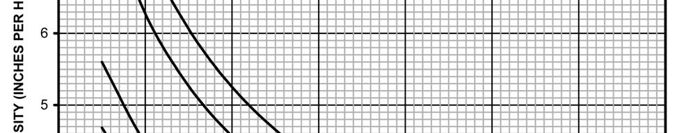
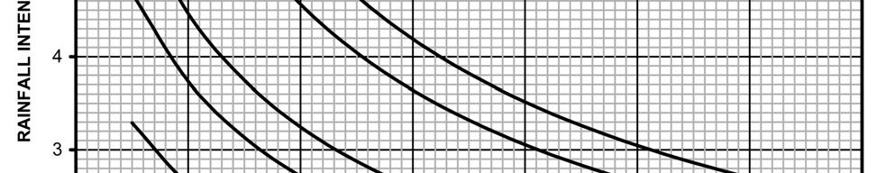
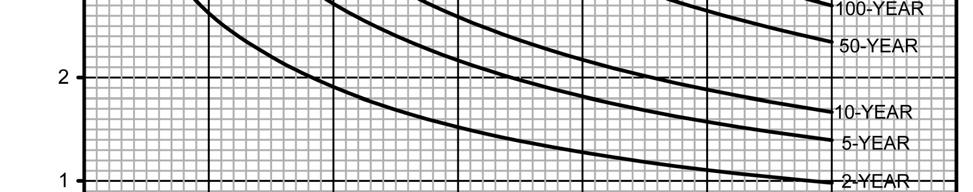
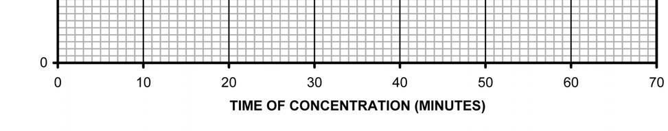
100 Chapter 6. Hydrology FIGURE 6-1 RAINFALL INTENSITY-DURATION CURVE ARAPAHOE COUNTY, COLORADO Arapahoe County Stormwater Management Manual Page 6-11
101 Chapter 6. Hydrology FIGURE 6-2 STANDARD SF-2 FORM Arapahoe County Stormwater Management Manual Page 6-12
102 Chapter 6. Hydrology FIGURE 6-3 STANDARD SF-3 FORM Arapahoe County Stormwater Management Manual Page 6-13
103 Chapter 7. Street Drainage 7.0 Introduction This chapter summarizes methods to evaluate runoff conveyance in various street cross sections and curb types in Arapahoe County and identifies acceptable upper limits of street capacity for minor and major storm events. Sections 7.1 through 7.6 address conventional curb-and-gutter street sections used in the County. The use of roadside ditches in rural portions of the County is covered in Section Stormwater Quality Considerations. A concept that holds promise for reducing urban runoff and pollutant loading consists of curbless (or intermittent curb) streets with adjacent grass swales. This concept gives street runoff a chance to infiltrate and get filtered and slowed in the vegetated swales. The use of curbless streets with grass swales for runoff reduction and enhanced water quality is discussed in Section Function of Streets in the Drainage System Primary Function of Streets. Urban streets not only carry traffic, but stormwater runoff as well. The primary function of urban streets is for traffic movement; therefore, the drainage function is subservient and must not interfere with the traffic function of the street. When runoff in the street exceeds allowable limits, a storm sewer system or open channel is required to convey the excess flows Design Criteria Based on Frequency and Magnitude. The design criteria for the collection and conveyance of storm water runoff on public streets are based on an allowable frequency and magnitude of traffic interference. The primary design objective is to keep the depth and spread (encroachment) of stormwater on the street below an acceptable value for a given storm event Street Function in Minor (5-year) Storm Event. The primary function of streets in a minor storm event is to convey the nuisance flows quickly and efficiently to the next intended drainage conveyance system with minimal disruption to street traffic Street Function in Major (100-year) Storm Event. For the major storm event, the function of streets is to provide an emergency passageway for flood flows while maintaining public safety and minimizing flood damage. In the major event, the street becomes an open channel and must be analyzed to determine when flooding depths exceed acceptable levels. 7.2 Street Classification Arapahoe County Standard Roadway Sections. The current standard roadway sections in Arapahoe County were modified in 2005 and are published in the 2006 update of the Arapahoe County Infrastructure Design and Construction Standards. For new development projects, the current roadway sections usually apply. Information pertaining to the former (1986) Arapahoe County Stormwater Management Manual Page 7-1
104 Chapter 7. Street Drainage County cross sections is also included in this Manual for use when the street section is consistent with the previous County standards. Each roadway section has a different capacity, so it is important to use the section dimensions or capacity chart that applies to the particular street section of interest. The capacity charts located at the end of this chapter indicate the dimensions of the applicable roadway section. The use of these charts is discussed in Section Drainage Classification. The streets in the County are assigned a drainage classification of Type A, B, or C based on the average daily traffic (ADT) for which the street is designed or for the roadway classification. In general, the higher the ADT or mobility that the roadway provides, the more restrictive the allowable drainage encroachment into the driving lanes. The following tables summarize the drainage classification for each County roadway section: TABLE 7-1 DRAINAGE CLASSIFICATION FOR CURRENT ROADWAY SECTIONS Street Classification Urban Private - Parking One Side Urban Private - Parking Both Sides Public Urban Local Two-Lane Collector Four-Lane Collector Four-Lane Arterial with Painted Median Four-Lane Arterial with Raised Median Six-Lane Principal Arterial / Urban Expressway Eight-Lane Urban Expressway Drainage Classification A A A B B C C C C TABLE 7-2 DRAINAGE CLASSIFICATION FOR FORMER (1986) ROADWAY SECTIONS Drainage Street Classification Classification Urban Local A 60 Minor Collector B 80 Major Collector B 100 Minor Arterial C 120 (4-Lane) Major Arterial C 140 (6-Lane) Major Arterial C 7.3 Minor (5-year) Storm Allowable Street Flow Allowable Flow Depth and Roadway Encroachment for Streets with Curb and Gutter. The County allows the use of streets for drainage conveyance in the minor storm with limitations on the depth of flow in the curb and gutter and the spread of flow onto the roadway. The following table Arapahoe County Stormwater Management Manual Page 7-2
105 Chapter 7. Street Drainage summarizes these limitations for each drainage classification. The maximum allowable street capacity is determined by whichever limitation is more restrictive, based on the geometry of the street section. TABLE 7-3 MINOR STORM ALLOWABLE FLOW DEPTH AND ROADWAY ENCROACHMENT FOR STREETS WITH CURB AND GUTTER Drainage Allowable Maximum Street Encroachment Classification Flow Depth in Gutter Flowline 1 Type A No curb overtopping. Flow may spread to crown of street. Type B No curb overtopping. Flow spread must leave at least one 10- foot lane free of water. (5-feet either side of the street crown) Type C No curb overtopping. Flow spread must leave at least two 10- foot lanes free of water. (10-feet each side of the street crown or median) 1 If a 4-inch curb with an attached sidewalk is used (i.e. combination or rollover curb), the allowable depth of flow is to the back of sidewalk. 7.4 Major (100-year) Storm Allowable Street Flow Allowable Flow Depth for a Street with Curb and Gutter. The County allows the use of streets for drainage conveyance in the major storm with limitations on the depth of flow in the curb and gutter and the containment of flow within the roadway right-of-way or dedicated easements. The following table summarizes these limitations for each drainage classification. The maximum street capacity is determined by whichever of these criteria is first reached based on the geometry of the street section. TABLE 7-4 MAJOR STORM ALLOWABLE DEPTH AND CONTAINMENT OF FLOW FOR STREETS WITH CURB AND GUTTER Drainage Allowable Flow Depth Containment of Flow Classification Type A, B and C The depth of water at the gutter flowline shall not exceed 12-inches. Flow must be contained within public right-of-way or dedicated drainage easements, AND All structures shall be a minimum of 1- foot above the 100-year water surface elevation 1. 1 For a structure with a first floor elevation below the curb elevation, an 18-inch high berm must be constructed between the curb and the house, including at any driveways, to contain flow in the street section. If the flow is not contained within a berm, then the allowable flow in each side of the street shall not exceed the allowable flow shown for the minor (5-year) storm. Arapahoe County Stormwater Management Manual Page 7-3
106 Chapter 7. Street Drainage 7.5 Hydraulic Evaluation of Street Capacity Once the design discharge is calculated (see Chapter 6, Hydrology), hydraulic calculations are to be completed to determine the capacity of street gutters and the resulting encroachment onto the street section. All street capacity and encroachment calculations shall conform to the Streets/Inlets/Storm Sewers chapter of the UDFCD Manual unless otherwise noted herein. For more detailed information on the methodology used for the hydraulic evaluation of street capacity see the UDFCD Manual, Streets/Inlets/Storm Sewers chapter Minor (5-year) Storm Street Capacity Worksheet. The Streets/Inlets/Storm Sewers chapter of the UDFCD Manual provides an analysis tool used for determining the minor storm street capacity and flow encroachment. The Q- Allow worksheet is contained within the UD-Inlet spreadsheet which can be accessed via the internet at This worksheet completes a hydraulic evaluation of the theoretical street capacity for the minor storm by calculating the theoretical minor event street gutter flow capacity based on both 1) the allowable spread and 2) the allowable gutter depth. A reduction factor is then applied to the theoretical gutter flow based on allowable depth and the lesser of the allowable street capacities governs for the minor event Minor Storm Street Capacity Charts. The allowable minor storm street capacity for both the current and former (1986) Arapahoe County street cross-sections have been calculated based on the Q-Allow worksheet and are presented at the end of this chapter. These charts shall only be used for streets that are consistent with all the referenced standard street parameters, including street width, pavement cross slope of 2%, and a depressed gutter consistent with the County s standard cross-section as noted. A Manning s n-value of was used. These minor event capacity calculations were performed for various street slopes to generate the street capacity charts located at the end of this chapter. These charts present the allowable capacity for one-half of the street section, on one side of the street crown or the other. Standard capacity charts have not been provided for the High Speed Type 2 curb and gutter (CDOT M&S Standards), and therefore street capacities must be calculated when using this type of curb and gutter section. See Section for more information Major (100-year) Storm Street Capacity Worksheet. Similar to the minor storm, the Streets/Inlets/Storm Sewers chapter of the UDFCD Manual provides an analysis tool used for determining the major storm street capacity. The Q-Allow worksheet is contained within the UD-Inlet spreadsheet which can be accessed via the internet at This worksheet completes a hydraulic evaluation of the theoretical street capacity for the major storm and then applies the major storm reduction factor Major Storm Street Capacity Charts. The allowable major storm street capacity for both the current and former (1986) Arapahoe County street cross-sections have been calculated based on the Q-Allow worksheet and are presented at the end of this chapter. These charts shall only be used for Arapahoe County Stormwater Management Manual Page 7-4
107 Chapter 7. Street Drainage streets that are consistent with all the referenced standard street parameters, including street width, pavement cross slope of 2%, and a depressed gutter consistent with the County s standard cross-section as noted. A Manning s n-value of was used. These charts present the allowable capacity for one-half of the street section, on one side of the street crown or the other. The major storm street capacity charts at the end of this chapter contain two curves which represent the capacities at full curb depth and at 12-inches of depth at the gutter flowline, respectively. The 12-inch depth allowable capacity curve is based on the assumption of a vertical wall at the back of the curb. Although flow may be conveyed in the area behind the curb, the additional capacity is ignored to account for potential obstructions in the gutter and to allow for a reasonable capacity to be calculated, independent of the various grading scenarios and landscaping improvements that may be proposed adjacent to the roadway. The 12-inch depth curve may be used if the following conditions apply: 1. The major storm flow must be fully contained at the assumed depth within public right-of-way or easements. 2. A minimum of 1 foot above the assumed depth of 12-inches will be provided as freeboard to the lowest floor or window well openings for structures that are proposed adjacent to the roadway. 3. The grading behind the curb or sidewalk provides for the containment of the major storm flows at the assumed 12 inch depth, and there are no diversions at driveways, intersections or other locations prior to the designed outfall point. It is the responsibility of the design engineer to verify that all of the conditions are satisfied. If these conditions are not met, the allowable capacity in each side of the street during the major storm shall be the same as shown for the minor storm. Both the minor and major curves are shown in order to assist the design engineer in determining the appropriate street capacity based on gutter flow depth in order to meet the County Criteria. Due to the large scale of the major storm capacity chart, the design engineer may refer to the minor storm street capacity chart to read a more accurate allowable capacity for the gutter full condition Major Storm Street Capacity with Flow Depth Between Curb Full and 12- inches. There may be situations when the conditions in Section can be satisfied when the major storm flow depth (at the gutter flowline) is between curb full and 12-inches of depth. An example of this situation would be when the lowest point of water entry into a structure is 20-inches above the gutter flowline. Since the finished floor elevation must be at least 1-foot above the assumed gutter flow elevation, the maximum gutter flow depth would be limited to 8-inches (20-inches minus 12-inches). The design engineer may use the Q-Allow worksheet in UD-Inlet to determine the street capacity at the specific depth between curb full and 12-inches of depth at the flowline, based on the other assumptions presented in Section Arapahoe County Stormwater Management Manual Page 7-5
108 Chapter 7. Street Drainage Non-Standard Street Sections. When a County standard street section is not used, the design engineer should use the Q-Allow worksheet in the UDFCD Manual to determine the allowable gutter capacity. The engineer must enter the data appropriate for the street section and the minor/major storm criteria for the drainage classification for the worksheet to calculate the allowable gutter capacity based on the data and criteria provided. 7.6 Cross-Street Flow Cross-Street Flow Conditions. Cross-street flow can occur in an urban drainage system under three conditions. One condition occurs when the runoff in a gutter spreads across the street crown to the opposite gutter. The second is when cross pans are used. The third condition is when the flow in a drainageway exceeds the capacity of a road culvert and/or bridge and subsequently overtops the crown of the street. Criteria for the first two conditions are discussed in the following sections. The third condition regarding allowable cross-street flow and overtopping at culvert crossings is limited by the criteria provided in Chapter 11, Culverts and Bridges Influence on Traffic. Whenever storm runoff, other than sheet flow, moves across a traffic lane, traffic movement is affected. The cross flow may be caused by super-elevation of a curve, by the intersection of two streets, by exceeding the capacity of the higher gutter on a street with cross fall, or street design that has not met the criteria provided herein. The problem associated with this type of flow is that it is localized in nature and vehicles may be traveling at speeds that are incompatible with the cross flow when they reach the location Allowable Cross-Street Flow Due to Spread Over the Street Crown. Allowable cross-street flow depths when the flow depth exceeds the street crown elevation are provided in Table 7-5. In the minor storm event, crossstreet flow is NOT allowed based on the allowable flow depth and encroachment criteria provided in Table 7-3. In the major storm event, allowable cross-street flow is controlled by the criteria and limitations presented in Table 7-4 and Table 7-5. For example, if the maximum allowable gutter flow depth is 12-inches and the crown of the road is 7-inches above the flowline of the gutter, 5-inches (12-inches minus 7-inches) of cross-street flow is allowed during a major storm event, assuming all other criteria shown in Table 7-4 are met. TABLE 7-5 ALLOWABLE CROSS-STREET FLOW DUE TO SPREAD OVER THE STREET CROWN FOR STREETS WITH CURB AND GUTTER Drainage Classification Minor Storm System Maximum Depth Major Storm System Maximum Flow Depth Type A, B and C Not allowed 12-inches of depth at gutter flowline. Note: All criteria in Table 7-4 must also be met for the major storm event. Arapahoe County Stormwater Management Manual Page 7-6
109 Chapter 7. Street Drainage Cross-Street Flow Analysis. The analysis to quantify the amount of crossstreet flow can be complex due to the fact that the runoff is moving longitudinally down the street. In addition, it is often assumed that runoff being conveyed in the gutter will follow the path of the associated gutter at intersections, which generally requires the full flow to turn corners, without the appropriate consideration being given to the momentum that was established in one direction. There is potential for cross-street flow, if the flow isn t conveyed around the corner, as assumed. It is the responsibility of the design engineer to make conservative assumptions relative to crossstreet flow and to design the downstream inlets and storm sewer accordingly. Even if the criteria stated above are met, the County will require inlets and storm sewers on the upstream side of the street to be designed to fully convey design flows assuming no cross-flow. Also, inlets and storm sewers on the downstream side of the street shall be increased in capacity by the amount of 1.5 times the estimated cross-flow Crosspans. The use of crosspans shall adhere to the criteria presented in the Arapahoe County Infrastructure Design and Construction Standards. Crosspans shall be designed to convey the minor and major storm event within the criteria presented in Sections 7.3 and 7.4. The design engineer shall evaluate the carrying capacity (with calculations provided) of water on the roadway being considered as well as the side street. 7.7 Curbless Streets with Roadside Swales for Enhanced Water Quality Urban Roadside Swales. Urban roadside swale sections should not be confused with rural street sections. Rural street sections incorporate a roadside ditch, which typically have a deeper section with steeper side slopes. Urban roadside swales provide an opportunity to minimize directly connected impervious areas and thereby reduce the volume and peak rate of runoff and enhance stormwater quality. Roadside swales are used in conjunction with curbless (or intermittent curb) streets. Urban roadside swales can also be utilized to meet onsite water quality enhancement requirements for sites that are tributary to a regional water quality facility, as further defined in Section In such cases, the water quality design should meet the grass swale requirements Section If urban roadside swales are used to minimize directly connected impervious areas without providing formal water quality enhancements, the design shall be based on site-specific conditions. However, they will generally have a depth of 6- to 9-inches below the edge of pavement, a bottom width of at least 2-feet and side slopes of 8:1 or flatter. Swales shall be vegetated with irrigated bluegrass or irrigated sod-forming native grasses. The invert of the swale shall be parallel to the street slope to provide a constant depth. The use of urban roadside swales will need to be approved by the County prior to submittal. The engineer shall use the Arapahoe County Infrastructure Arapahoe County Stormwater Management Manual Page 7-7
110 Chapter 7. Street Drainage Design and Construction Standards and the minimum urban swale criteria in the next section to determine the appropriate standard street section(s) for the project and seek approval for an alternate street section, as necessary Allowable Capacity. The allowable flow depth and roadway encroachment in the minor and major storm events for curbless streets can be found in Tables 7-3 and 7-4. Tables 7-3 and 7-4 reference allowable flow depth based on the gutter flow line; these tables should be used for curbless streets by applying the depth at the edge of pavement (rather than gutter flowline). Flow in the grass swale is limited by capacity (this generally governs at low street slopes) and by velocity considerations (this governs at higher street slopes). To limit the potential for erosion during the 100-year event, allowable capacity for roadside grass swales is based on the major storm. A minimum velocity shall not be less than 2-fps, and the maximum Froude Number should not exceed 0.8. The lowest point of water entry (first floor or basement window) of any structure adjacent to the swale shall be at least 1.0-feet above the 100-year water surface, or generally 2.0 feet above the edge of the road Driveways and Street Cross-flow. In general, driveways or sidewalks that cross the swale are intended to conform to the swale cross section, such that flow will pass over the driveway as opposed to under it. Trench drains are generally required at the low point in the drive to convey any nuisance flows. Cross pans are typically used to convey swale flow across a street Downstream Facilities. At the point where the maximum capacity or slope of the swale is reached for the design event, runoff must be conveyed in an alternate system. The swale flow shall be diverted into a vegetated drainageway or picked up in an area inlet and storm sewer. Of the two, a vegetated drainageway is preferred to provide further contact of runoff with vegetation and soil. Drainageway design shall be in accordance with Chapter 12, Open Channel Design. Inlets and storm sewers shall be designed in accordance with Chapter 8, Inlets, and Chapter 9, Storm Sewers. 7.8 Rural Roadside Ditches Roadside Ditches. Roadside ditches shall be used in lieu of curb and gutter when rural street sections are approved. Maintenance shall be considered when designing and using roadside ditches, including adequate area and side slopes to allow for maintenance access and vehicles. Maximum side slopes of 4 (horizontal) to 1 (vertical) are preferred, although maximum side slopes of 3 to 1 are acceptable if provided with erosion control blanket in accordance with the County s GESC criteria. Based on the velocity within roadside ditch, the County may require additional erosion control protections. Roadside ditches shall be included in the street right-of-way section.. Arapahoe County Stormwater Management Manual Page 7-8
111 Chapter 7. Street Drainage Roadside Ditch Design Criteria. The allowable flow depth and roadway encroachment in the minor and major storm events for rural roadside ditches can be found in Tables 7-3 and 7-4. Tables 7-3 and 7-4 reference allowable flow depth based on the gutter flow line; these tables should be used for rural roadside ditches by applying the depth at the edge of pavement (rather than gutter flowline). The spread of flow shall not extend outside the street right-ofway and at least 12-inches of freeboard shall be provided from the major storm water surface elevation to the lowest point of water entry at any adjacent structures. Rural roadside ditches shall be designed in accordance with the criteria for minor drainageway grass-lined channels shown in Chapter 12, Open Channel Design. Grade control structures are required to maintain velocities less than the maximum allowable or riprap lining (soil filled) shall be provided in accordance with the Major Drainage section of the UDFCD Manual. There are cases when the roadside ditch criteria may need to be more stringent due to the function of the rural road. Even if a rural road has a low traffic volume, it may be important for emergency access to several properties and therefore require special design criteria. The County reserves the right for more stringent criteria for single point access roads. See Chapter 11, Culverts and Bridges, for design criteria pertaining to rural roadside ditch culverts. Arapahoe County Stormwater Management Manual Page 7-9
112 Chapter 7. Street Drainage FIGURE 7-1, ARAPAHOE COUNTY STREET CAPACITY CHART URBAN PRIVATE PARKING ONE SIDE (4 CURB) Typical Cross Section 30' FLOWLINE TO FLOWLINE 4" COMBINATION CURB 2% 2% MINOR STORM MAX SPREAD (T) = 14.4' 4" COMBINATION CURB Gutter Capacity (cfs) Minor Storm Street Capacity Chart 1,2,4, Slope (%) Gutter Capacity (cfs) Major Storm Street Capacity Chart 1,3,4, Slope (%) 12-inch Depth Gutter-Full Depth 1 The Arapahoe County standard street section parameters must apply to use these charts. For non-standard sections, the street capacity shall be calculated using the UDFCD spreadsheets (see Section 7.5). The capacity shown is based on ½ the street section. 2 The maximum spread width is limited by the curb height based on no curb overtopping allowable during a minor storm. 3 Calculations for the 12-inch depth curve assume a vertical wall behind the top of curb. For the gutter-full depth case, the Minor Storm Capacity Chart may be used. 4 The capacity shown assumes gutter-full depth of 5.0 to the back of the attached sidewalk. If a 4 curb without an attached sidewalk is used, the street capacity shall be calculated using the UDFCD spreadsheets. 5 This chart represents the parking side of the street. Separate calculations must be made for the non-parking side of the street. Arapahoe County Stormwater Management Manual Page 7-10
113 Chapter 7. Street Drainage FIGURE 7-2, ARAPAHOE COUNTY STREET CAPACITY CHART URBAN PRIVATE PARKING ONE SIDE (6 CURB) Typical Cross Section 30' FLOWLINE TO FLOWLINE MINOR STORM MAX SPREAD (T) = 18' 6" VERTICAL CURB 2% 2% 6" VERTICAL CURB Gutter Capacity (cfs) Minor Storm Street Capacity Chart Slope (%) 140 Major Storm Street Capacity Chart 1,2 120 Gutter Capacity (cfs) Slope (%) 12-inch Depth Gutter-Full Depth 1 The Arapahoe County standard street section parameters must apply to use these charts. For non-standard sections, the street capacity shall be calculated using the UDFCD spreadsheets (see Section 7.5). The capacity shown is based on ½ the street section. 2 Calculations for the 12-inch depth curve assume a vertical wall behind the top of curb. For the gutter-full depth case, the Minor Storm Capacity Chart may be used. Arapahoe County Stormwater Management Manual Page 7-11
114 Chapter 7. Street Drainage FIGURE 7-3, ARAPAHOE COUNTY STREET CAPACITY CHART URBAN PRIVATE PARKING BOTH SIDES (4 CURB) Typical Cross Section 36' FLOWLINE TO FLOWLINE 4" COMBINATION CURB 2% 2% MINOR STORM MAX SPREAD (T) = 14.4' 4" COMBINATION CURB Gutter Capacity (cfs) Minor Storm Street Capacity Chart 1,2, Slope (%) Gutter Capacity (cfs) Major Storm Street Capacity Chart 1,3, Slope (%) 12-inch Depth Gutter-Full Depth 1 The Arapahoe County standard street section parameters must apply to use these charts. For non-standard sections, the street capacity shall be calculated using the UDFCD spreadsheets (see Section 7.5). The capacity shown is based on ½ the street section. 2 The maximum spread width is limited by the curb height based on no curb overtopping allowable during a minor storm. 3 Calculations for the 12-inch depth curve assume a vertical wall behind the top of curb. For the gutter-full depth case, the Minor Storm Capacity Chart may be used. 4 The capacity shown assumes gutter-full depth of 5.0 to the back of the attached sidewalk. If a 4 curb without an attached sidewalk is used, the street capacity shall be calculated using the UDFCD spreadsheets. Arapahoe County Stormwater Management Manual Page 7-12
115 Chapter 7. Street Drainage FIGURE 7-4, ARAPAHOE COUNTY STREET CAPACITY CHART URBAN PRIVATE PARKING BOTH SIDES (6 CURB) Typical Cross Section 36' FLOWLINE TO FLOWLINE MINOR STORM MAX SPREAD (T) = 18' 6" VERTICAL CURB 2% 2% 6" VERTICAL CURB Gutter Capacity (cfs) Minor Storm Street Capacity Chart Slope (%) 140 Major Storm Street Capacity Chart 1,2 Gutter Capacity (cfs) Slope (%) 12-inch Depth Gutter-Full Depth 1 The Arapahoe County standard street section parameters must apply to use these charts. For non-standard sections, the street capacity shall be calculated using the UDFCD spreadsheets (see Section 7.5). The capacity shown is based on ½ the street section. 2 Calculations for the 12-inch depth curve assume a vertical wall behind the top of curb. For the gutter-full depth case, the Minor Storm Capacity Chart may be used. Arapahoe County Stormwater Management Manual Page 7-13
116 Chapter 7. Street Drainage FIGURE 7-5, ARAPAHOE COUNTY STREET CAPACITY CHART URBAN LOCAL (4 CURB) Typical Cross Section 34' FLOWLINE TO FLOWLINE MINOR STORM MAX SPREAD (T) = 14.4' 4" COMBINATION CURB 2% 2% 4" COMBINATION CURB Gutter Capacity (cfs) Minor Storm Street Capacity Chart 1,2, Slope (%) Gutter Capacity (cfs) Major Storm Street Capacity Chart 1,3, Slope (%) 12-inch Depth Gutter-Full Depth 1 The Arapahoe County standard street section parameters must apply to use these charts. For non-standard sections, the street capacity shall be calculated using the UDFCD spreadsheets (see Section 7.5). The capacity shown is based on ½ the street section. 2 The maximum spread width is limited by the curb height based on no curb overtopping allowable during a minor storm. 3 Calculations for the 12-inch depth curve assume a vertical wall behind the top of curb. For the gutter-full depth case, the Minor Storm Capacity Chart may be used. 4 The capacity shown assumes gutter-full depth of 5.0 to the back of the attached sidewalk. If a 4 curb without an attached sidewalk is used, the street capacity shall be calculated using the UDFCD spreadsheets. Arapahoe County Stormwater Management Manual Page 7-14
117 Chapter 7. Street Drainage FIGURE 7-6, ARAPAHOE COUNTY STREET CAPACITY CHART URBAN LOCAL (6 CURB) Typical Cross Section 34' FLOWLINE TO FLOWLINE MINOR STORM MAX SPREAD (T) = 17' 6" VERTICAL CURB 2% 2% 6" VERTICAL CURB Minor Storm Street Capacity Chart 1 Gutter Capacity (cfs) Slope (%) 120 Major Storm Street Capacity Chart 1,2 Gutter Capacity (cfs) Slope (%) 12-inch Depth Gutter-Full Depth 1 The Arapahoe County standard street section parameters must apply to use these charts. For non-standard sections, the street capacity shall be calculated using the UDFCD spreadsheets (see Section 7.5). The capacity shown is based on ½ the street section. 2 Calculations for the 12-inch depth curve assume a vertical wall behind the top of curb. For the gutter-full depth case, the Minor Storm Capacity Chart may be used. Arapahoe County Stormwater Management Manual Page 7-15
118 Chapter 7. Street Drainage FIGURE 7-7, ARAPAHOE COUNTY STREET CAPACITY CHART TWO-LANE COLLECTOR Typical Cross Section 50' FLOWLINE TO FLOWLINE MINOR STORM MAX SPREAD (T) = 18.7' 2% 2% 6" VERTICAL CURB 6" VERTICAL CURB 25 Minor Storm Street Capacity Chart 1,2 Gutter Capacity (cfs) Slope (%) Gutter Capacity (cfs) Major Storm Street Capacity Chart 1, Slope (%) 12-inch Depth Gutter-Full Depth 1 The Arapahoe County standard street section parameters must apply to use these charts. For non-standard sections, the street capacity shall be calculated using the UDFCD spreadsheets (see Section 7.5). The capacity shown is based on ½ the street section. 2 The maximum spread width is limited by the curb height based on no curb overtopping allowable during a minor storm. 3 Calculations for the 12-inch depth curve assume a vertical wall behind the top of curb. For the gutter-full depth case, the Minor Storm Capacity Chart may be used. Arapahoe County Stormwater Management Manual Page 7-16
119 Chapter 7. Street Drainage FIGURE 7-8, ARAPAHOE COUNTY STREET CAPACITY CHART FOUR-LANE COLLECTOR Typical Cross Section 62' FLOWLINE TO FLOWLINE MINOR STORM MAX SPREAD (T) = 18.7' 6" VERTICAL CURB 2% 2% 6" VERTICAL CURB 25 Minor Storm Street Capacity Chart 1,2 Gutter Capacity (cfs) Slope (%) Gutter Capacity (cfs) Major Storm Street Capacity Chart 1, Slope (%) 12-inch Depth Gutter-Full Depth 1 The Arapahoe County standard street section parameters must apply to use these charts. For non-standard sections, the street capacity shall be calculated using the UDFCD spreadsheets (see Section 7.5). The capacity shown is based on ½ the street section. 2 The maximum spread width is limited by the curb height based on no curb overtopping allowable during a minor storm. 3 Calculations for the 12-inch depth curve assume a vertical wall behind the top of curb. For the gutter-full depth case, the Minor Storm Capacity Chart may be used. Arapahoe County Stormwater Management Manual Page 7-17
120 Chapter 7. Street Drainage FIGURE 7-9, ARAPAHOE COUNTY STREET CAPACITY CHART FOUR-LANE ARTERIAL WITH PAINTED MEDIAN Typical Cross Section 78' FLOWLINE TO FLOWLINE MINOR STORM MAX SPREAD (T) = 18.7' 6" VERTICAL CURB 2% 2% 6" VERTICAL CURB 25 Minor Storm Street Capacity Chart 1,2 Gutter Capacity (cfs) Slope (%) Gutter Capacity (cfs) Major Storm Street Capacity Chart 1, Slope (%) 12-inch Depth Gutter-Full Depth 1 The Arapahoe County standard street section parameters must apply to use these charts. For non-standard sections, the street capacity shall be calculated using the UDFCD spreadsheets (see Section 7.5). The capacity shown is based on ½ the street section. 2 The maximum spread width is limited by the curb height based on no curb overtopping allowable during a minor storm. 3 Calculations for the 12-inch depth curve assume a vertical wall behind the top of curb. For the gutter-full depth case, the Minor Storm Capacity Chart may be used. Arapahoe County Stormwater Management Manual Page 7-18
121 Chapter 7. Street Drainage FIGURE 7-10, ARAPAHOE COUNTY STREET CAPACITY CHART FOUR-LANE ARTERIAL WITH RAISED MEDIAN 32' FLOWLINE TO FLOWLINE Typical Cross Section 14' MEDIAN MINOR STORM MAX SPREAD (T) = 18.7' 6" VERTICAL CURB 2% 2% 6" VERTICAL CURB 25 Minor Storm Street Capacity Chart 1,2 Gutter Capacity (cfs) Slope (%) Gutter Capacity (cfs) Major Storm Street Capacity Chart 1, Slope (%) 12-inch Depth Gutter-Full Depth 1 The Arapahoe County standard street section parameters must apply to use these charts. For non-standard sections, the street capacity shall be calculated using the UDFCD spreadsheets (see Section 7.5). The capacity shown is based on ½ the street section. 2 The maximum spread width is limited by the curb height based on no curb overtopping allowable during a minor storm. 3 Calculations for the 12-inch depth curve assume a vertical wall behind the top of curb. For the gutter-full depth case, the Minor Storm Capacity Chart may be used. Arapahoe County Stormwater Management Manual Page 7-19
122 Chapter 7. Street Drainage FIGURE 7-11, ARAPAHOE COUNTY STREET CAPACITY CHART SIX-LANE PRINCIPAL ARTERIAL /URBAN EXPRESSWAY Typical Cross Section 39' FLOWLINE TO FLOWLINE 26' MEDIAN MINOR STORM MAX SPREAD (T) = 18.7' 6" VERTICAL CURB 2% 2% 6" VERTICAL CURB 25 Minor Storm Street Capacity Chart 1,2 Gutter Capacity (cfs) Slope (%) Gutter Capacity (cfs) Major Storm Street Capacity Chart 1, Slope (%) 12-inch Depth Gutter-Full Depth 1 The Arapahoe County standard street section parameters must apply to use these charts. For non-standard sections, the street capacity shall be calculated using the UDFCD spreadsheets (see Section 7.5). The capacity shown is based on ½ the street section. 2 The maximum spread width is limited by the curb height based on no curb overtopping allowable during a minor storm. 3 Calculations for the 12-inch depth curve assume a vertical wall behind the top of curb. For the gutter-full depth case, the Minor Storm Capacity Chart may be used. Arapahoe County Stormwater Management Manual Page 7-20
123 Chapter 7. Street Drainage FIGURE 7-12, ARAPAHOE COUNTY STREET CAPACITY CHART EIGHT-LANE URBAN EXPRESSWAY 51' FLOWLINE TO FLOWLINE Typical Cross Section 26' MEDIAN MINOR STORM MAX SPREAD (T) = 18.7' 6" VERTICAL CURB 2% Minor Storm Street Capacity Chart 1,2 2% 6" VERTICAL CURB Gutter Capacity (cfs) Slope (%) Gutter Capacity (cfs) Major Storm Street Capacity Chart 1, Slope (%) 12-inch Depth Gutter-Full Depth 1 The Arapahoe County standard street section parameters must apply to use these charts. For non-standard sections, the street capacity shall be calculated using the UDFCD spreadsheets (see Section 7.5). The capacity shown is based on ½ the street section. 2 The maximum spread width is limited by the curb height based on no curb overtopping allowable during a minor storm. 3 Calculations for the 12-inch depth curve assume a vertical wall behind the top of curb. For the gutter-full depth case, the Minor Storm Capacity Chart may be used. Arapahoe County Stormwater Management Manual Page 7-21
124 Chapter 7. Street Drainage FIGURE 7-13, ARAPAHOE COUNTY STREET CAPACITY CHART URBAN LOCAL (4 CURB) (1986 MANUAL) 4" COMBINATION CURB Typical Cross Section 36' FLOWLINE TO FLOWLINE 2% 2% Minor Storm Street Capacity Chart 1,2,4 MINOR STORM MAX SPREAD (T) = 14.4' 4" COMBINATION CURB Gutter Capacity (cfs) Slope (%) Major Storm Street Capacity Chart 1,3,4 Gutter Capacity (cfs) Slope (%) 12-inch Depth Gutter-Full Depth 1 The Arapahoe County standard street section parameters must apply to use these charts. For non-standard sections, the street capacity shall be calculated using the UDFCD spreadsheets (see Section 7.5). The capacity shown is based on ½ the street section. 2 The maximum spread width is limited by the curb height based on no curb overtopping allowable during a minor storm. 3 Calculations for the 12-inch depth curve assume a vertical wall behind the top of curb. For the gutter-full depth case, the Minor Storm Capacity Chart may be used. 4 The capacity shown assumes gutter-full depth of 5.0 to the back of the attached sidewalk. If a 4 curb without an attached sidewalk is used, the street capacity shall be calculated using the UDFCD spreadsheets. Arapahoe County Stormwater Management Manual Page 7-22
125 Chapter 7. Street Drainage FIGURE 7-14, ARAPAHOE COUNTY STREET CAPACITY CHART URBAN LOCAL (6 CURB) (1986 MANUAL) Typical Cross Section 36' FLOWLINE TO FLOWLINE MINOR STORM MAX SPREAD (T) = 18' 2% 2% 6" VERTICAL CURB 6" VERTICAL CURB Minor Storm Street Capacity Chart 1 Gutter Capacity (cfs) Slope (%) Major Storm Street Capacity Chart 1, Gutter Capacity (cfs) Slope (%) 12-inch Depth Gutter-Full Depth 1 The Arapahoe County standard street section parameters must apply to use these charts. For non-standard sections, the street capacity shall be calculated using the UDFCD spreadsheets (see Section 7.5). The capacity shown is based on ½ the street section. 2 Calculations for the 12-inch depth curve assume a vertical wall behind the top of curb. For the gutter-full depth case, the Minor Storm Capacity Chart may be used. Arapahoe County Stormwater Management Manual Page 7-23
126 Chapter 7. Street Drainage FIGURE 7-15, ARAPAHOE COUNTY STREET CAPACITY CHART 60 MINOR COLLECTOR (1986 MANUAL) Typical Cross Section 44' FLOWLINE TO FLOWLINE MINOR STORM MAX SPREAD (T) = 17' 6" VERTICAL CURB 2% 2% 6" VERTICAL CURB Gutter Capacity (cfs) Minor Storm Street Capacity Chart Slope (%) Major Storm Street Capacity Chart 1, Gutter Capacity (cfs) Slope (%) 12-inch Depth Gutter-Full Depth 1 The Arapahoe County standard street section parameters must apply to use these charts. For non-standard sections, the street capacity shall be calculated using the UDFCD spreadsheets (see Section 7.5). The capacity shown is based on ½ the street section. 2 Calculations for the 12-inch depth curve assume a vertical wall behind the top of curb. For the gutter-full depth case, the Minor Storm Capacity Chart may be used. Arapahoe County Stormwater Management Manual Page 7-24
127 Chapter 7. Street Drainage FIGURE 7-16, ARAPAHOE COUNTY STREET CAPACITY CHART 80 MAJOR COLLECTOR (1986 MANUAL) Typical Cross Section 64' FLOWLINE TO FLOWLINE MINOR STORM MAX SPREAD (T) = 18.7' 6" VERTICAL CURB 2% 2% 6" VERTICAL CURB 25 Minor Storm Street Capacity Chart 1,2 Gutter Capacity (cfs) Slope (%) Gutter Capacity (cfs) Major Storm Street Capacity Chart 1, Slope (%) 12-inch Depth Gutter-Full Depth 1 The Arapahoe County standard street section parameters must apply to use these charts. For non-standard sections, the street capacity shall be calculated using the UDFCD spreadsheets (see Section 7.5). The capacity shown is based on ½ the street section. 2 The maximum spread width is limited by the curb height based on no curb overtopping allowable during a minor storm. 3 Calculations for the 12-inch depth curve assume a vertical wall behind the top of curb. For the gutter-full depth case, the Minor Storm Capacity Chart may be used. Arapahoe County Stormwater Management Manual Page 7-25
128 Chapter 7. Street Drainage FIGURE 7-17, ARAPAHOE COUNTY STREET CAPACITY CHART 100 MINOR ARTERIAL (1986 MANUAL) Typical Cross Section 64' FLOWLINE TO FLOWLINE MINOR STORM MAX SPREAD (T) = 18.7' 6" VERTICAL CURB 2% 2% 6" VERTICAL CURB 25 Minor Storm Street Capacity Chart 1,2 Gutter Capacity (cfs) Slope (%) Gutter Capacity (cfs) Major Storm Street Capacity Chart 1, Slope (%) 12-inch Depth Gutter-Full Depth 1 The Arapahoe County standard street section parameters must apply to use these charts. For non-standard sections, the street capacity shall be calculated using the UDFCD spreadsheets (see Section 7.5). The capacity shown is based on ½ the street section. 2 The maximum spread width is limited by the curb height based on no curb overtopping allowable during a minor storm. 3 Calculations for the 12-inch depth curve assume a vertical wall behind the top of curb. For the gutter-full depth case, the Minor Storm Capacity Chart may be used. Arapahoe County Stormwater Management Manual Page 7-26
129 Chapter 7. Street Drainage FIGURE 7-18, ARAPAHOE COUNTY STREET CAPACITY CHART 120 (4 LANE) MAJOR ARTERIAL (1986 MANUAL) Typical Cross Section 27' FLOWLINE TO FLOWLINE 26' MEDIAN MINOR STORM MAX SPREAD (T) = 16' 6" VERTICAL CURB 2% 6" VERTICAL CURB Gutter Capacity (cfs) Minor Storm Street Capacity Chart Slope (%) Major Storm Street Capacity Chart 1,2 Gutter Capacity (cfs) Slope (%) 12-inch Depth Gutter-Full Depth 1 The Arapahoe County standard street section parameters must apply to use these charts. For non-standard sections, the street capacity shall be calculated using the UDFCD spreadsheets (see Section 7.5). The capacity shown is based on ½ the street section. 2 Calculations for the 12-inch depth curve assume a vertical wall behind the top of curb. For the gutter-full depth case, the Minor Storm Capacity Chart may be used. Arapahoe County Stormwater Management Manual Page 7-27
130 Chapter 7. Street Drainage FIGURE 7-19, ARAPAHOE COUNTY STREET CAPACITY CHART 140 (6 LANE) MAJOR ARTERIAL (1986 MANUAL) 39' FLOWLINE TO FLOWLINE Typical Cross Section 26' MEDIAN MINOR STORM MAX SPREAD (T) = 18.7' 6" VERTICAL CURB 2% 2% 6" VERTICAL CURB Minor Storm Street Capacity Chart 1,2 25 Gutter Capacity (cfs) Slope (%) Gutter Capacity (cfs) Major Storm Street Capacity Chart 1, Slope (%) 12-inch Depth Gutter-Full Depth 1 The Arapahoe County standard street section parameters must apply to use these charts. For non-standard sections, the street capacity shall be calculated using the UDFCD spreadsheets (see Section 7.5). The capacity shown is based on ½ the street section. 2 The maximum spread width is limited by the curb height based on no curb overtopping allowable during a minor storm. 3 Calculations for the 12-inch depth curve assume a vertical wall behind the top of curb. For the gutter-full depth case, the Minor Storm Capacity Chart may be used. Arapahoe County Stormwater Management Manual Page 7-28
131 Chapter 8. Inlets 8.0 Introduction This chapter provides criteria and design guides for evaluating and designing storm sewer inlets in Arapahoe County. The review of all planning submittals will be based on the criteria presented herein. 8.1 General Function of Inlets. The primary purpose of storm drain inlets is to intercept excess surface runoff and convey it into a storm drainage system, thereby reducing or eliminating surface flooding. Roadway geometry often dictates the location of street inlets located along the curb and gutter. In general, inlets are placed at all low points (sumps), median breaks, intersections, crosswalks, and along continuous grade curb and gutter. The spacing of inlets along a continuous grade segment of roadway is governed by the allowable spread of flow. See further details of allowable spread of flow in Chapter 7, Street Drainage of these Criteria Types of Inlets. There are two major types of inlets approved for use within the County rights-of-way: curb opening and grate. Inlets are further classified as being on a continuous grade or in a sump. Continuous grade refers to an inlet placed in curb and gutter such that the grade of the street has a continuous slope past the inlet and, therefore, water ponding does not occur at the inlet. The sump condition exists whenever an inlet is located at a low point and the result is ponding water General Design Guidelines. The following guidelines shall be used when designing inlets along a street section: 1. Design and location of inlets shall take into consideration pedestrian and bicycle traffic. Inlet grates shall be pedestrian and bicycle safe. Inlets may not be placed at pedestrian ramps and within the driveways. 2. Design and location of inlets shall be in accordance with the criteria established in Chapter 7, Street Drainage of these Criteria. 3. Maintenance of inlets shall be considered when determining inlet locations. The slope of the street, the potential for debris and ice accumulations, the distance between inlets and/or manholes etc., shall be considered. Maintenance access shall be provided to all inlets. 4. To avoid potential damage from large vehicles driving over the curb return, inlets shall not be placed in the curb return radii. 5. Selection of the appropriate inlet grate shall be based on a number of factors, including, but not limited to, the adjacent land use and potential for pedestrian or bicycle traffic, the potential for debris accumulation, visibility, expected loading from vehicles, and hydraulic capacity. 6. Consideration should be given to flanking inlets on each side of the low point when the depressed area has no outlet except through the system. The Arapahoe County Stormwater Management Manual Page 8-1
132 Chapter 8. Inlets purpose is to provide relief if the inlet at the low point becomes clogged. Consult HEC-22 for additional information regarding this concept. 7. In many cases, inlets are necessary at grade breaks, where street or ditch grades change from steep to relative flat because of the reduced conveyance capacities. In addition, it is common for icing or sediment deposition to occur with nuisance flows in reaches where the grades are relatively mild Inlet Capacity. The procedures used to define the capacity of standard inlets under continuous grade or sump flow conditions are described in the following sections. Unless otherwise noted in the following sections, all storm sewer inlet criteria shall be in accordance with the Streets/Inlets/Storm Sewers Chapter of the UDFCD Manual. In general, the procedure for calculating inlet capacity consists of defining the quantity and depth of flow in the gutter and determining the theoretical flow interception by the inlet. 8.2 Standard County Inlets Selection of Inlet Type. Table Applicable Settings for Various Inlet Types of the Streets/Inlets/Storm Sewers Chapter of the UDFCD Manual provides information on the appropriate application of the different types of inlets along with advantages and disadvantages of each. The information provided in this table shall be taken into consideration when selecting an inlet for a given site condition Standard Inlets Accepted for Use in the County. Table 8-1 provides the standard inlets permitted for use in the County: TABLE 8-1 STANDARD COUNTY INLETS Inlet Type Permitted Use Curb-Opening Inlet Type R All street types with 6-inch vertical curb and gutter and 4-inch mountable curb and gutter, with appropriate transitions. Type 13 Comb Inlet All street types with 6-inch vertical curb and gutter and 4-inch mountable curb and gutter, with appropriate transitions. (should be made bicycle safe) Grate Inlet - Type 16 Inlet All street types with 6-inch vertical curb and gutter and 4-inch mountable curb and gutter, with appropriate transitions. (should be made bicycle safe) Grate Inlet Type C Roadside or median grass swales; Landscaped area drains; used in sump condition Grate Inlet Type D Roadside or median grass swales; Landscaped area drains; used in sump condition Arapahoe County Stormwater Management Manual Page 8-2
133 Chapter 8. Inlets Note: Standard Details for the inlets referenced in this table can be found on the County s website at Along with the inlets mention in the table above, there are a large number of additional inlets which are used in the Denver Metro Area. Some of these inlets include the Denver Type 13 Inlet, and Vane Grate Inlet. The inlets provided in Table 8-1 are accepted for use in the County. For retrofit situations or when special circumstances exist, other inlets may be used but will be evaluated by the County in a case-by-case basis. UD-Inlet must be used for hydraulic analysis of these non-standard inlets. 8.3 Inlets on Continuous Grade Inlet Capacity Factors. The capacity of an inlet located on a continuous grade is dependent upon a variety of factors, including gutter slope, depth and velocity of flow in the gutter, height and length of the curb opening, street cross slope, and the amount of depression at the inlet. Inlets placed on continuous grades rarely intercept all of the flow in the gutter during the minor storm. This results in flow continuing downstream of the inlet and is typically referred to as carryover. The amount of carryover must be accounted for in the drainage system evaluation as well as in the design of the downstream inlet Curb Opening Inlet (Type R). The capture efficiency of a curb-opening inlet is dependent on the length of the opening, the depth of flow at the curb, the street cross slope, and the longitudinal gutter slope. If the curb opening is long, the flow rate is low, and the longitudinal gutter slope is small, all of the flow will be captured by the inlet. During the minor storm event, a portion of the stormwater often bypasses the inlet as indicated by the inlet efficiency. See the Streets/Inlets/Storm Sewers chapter of the UDFCD Manual for additional information on the efficiency and design of curb opening inlets on continuous grades Grated Inlet (Type 16). The capture efficiency of a grated inlet is highly dependent on the width and length of the grate and the velocity of gutter flow. If the gutter velocity is low and the spread of water does not exceed the grate width, all of the flow will be captured by the grated inlet. During the minor storm event, a portion of the stormwater often bypasses the inlet as indicated by the inlet efficiency. See the Streets/Inlets/Storm Sewers chapter of the UDFCD Manual for additional information on the efficiency and design of grated inlets on continuous grades Combination Inlet (Type 13 comb). Combination inlets take advantage of the debris removal capabilities of a curb opening inlet and the capture efficiency of a grate inlet. See the Streets/Inlets/Storm Sewers chapter of the UDFCD Manual for additional information on the efficiency and design of combination inlets on continuous grades. Arapahoe County Stormwater Management Manual Page 8-3
134 Chapter 8. Inlets 8.4 Hydraulic Evaluation - Inlets on Continuous Grade Preliminary Versus Final Design of Inlets on Continuous Grade. Capacity charts for Type R inlets on continuous grades along standard County street sections have been completed for the minor and major storm events, based on the maximum allowable flow in the street section. Further discussion on the use of the charts can be found in Sections and respectively. It is recommended that these charts be used for preliminary design phases and rough inlet placement. For final design, the design engineer can use these charts if the street is at maximum allowable flow. When flow in the gutter is less than maximum flow, the UD-Inlet spreadsheets shall be used to determine the interception by the proposed inlet. Further discussion on the use of UD-Inlet for less than maximum allowable flow can be found in Section Inlet Analysis Spreadsheets. The Streets/Inlets/Storm Sewers chapter of the UDFCD Manual provides detailed instruction on the appropriate analysis of inlet capacities including equations, coefficients, and examples. The worksheets are the most accurate means of determining inlet capture rates and capacity calculations. The UD-Inlet Spreadsheets may be downloaded from the UDFCD web site at Minor Event Curb Opening Inlet Capacity Charts for Standard Street Sections at Maximum Capacity. The County requires Type R curb opening inlets be used in the County. Minor event inlet capacity charts for curb opening inlets on continuous grades along standard County street sections have been generated and can be found at the end of this chapter. Charts for the current Arapahoe County street sections, adopted in 2005, and the former sections, dating from 1986, are both shown. The curb opening inlet capacity charts were calculated based on the maximum flow allowed in the street gutter for the minor design storm. These charts also incorporate clogging factors as discussed in the Streets/Inlets/Storm Sewers chapter of the UDFCD Manual. Chapter 7, Street Drainage, provides additional information on the current and former street sections and on the maximum street flow allowed for the minor storm event Major Event Curb Opening Inlet Capacity Charts for Standard Street Sections at Maximum Capacity. Major event inlet capacity charts for curb opening inlets on continuous grades along standard County street sections (current and former) have also been generated and can be found at the end of this chapter. These inlet capacity charts were calculated based on the maximum flow allowed in the street gutter for the major design storm. Chapter 7, Street Drainage, provides additional information on the maximum street flow allowed for the major storm event. The major storm inlet capacity charts contain two curves which correspond to the street capacity charts generated in Chapter 7. The two curves represent both 6-inches and 12-inches of depth at the gutter flowline. Both curves are provided to assist the design engineer in calculating the inlet capacity based upon the gutter flow depth that meets the County street flow criteria. Due to the large scale of the major storm inlet capacity chart, the minor storm inlet capacity chart may be used to determine a more accurate interception Arapahoe County Stormwater Management Manual Page 8-4
135 Chapter 8. Inlets rate for the gutter-full condition. These inlet capacity charts also incorporate clogging factors as discussed in the Streets/Inlets/Storm Sewers chapter of the UDFCD Manual Procedure for Street Flows Less Than Maximum Allowable. For final design, if the quantity of flow in the street is less than the maximum allowable flow (minor or major event) as determined per the Street Drainage chapter of these Criteria, then the design engineer must determine the interception rate of the inlet using UD-Inlet based on the actual flow in the gutter Non-Standard Street Sections and Other Types of Inlets. There are two additional cases when the design engineer must use the UD-Inlet worksheets in the UDFCD Manual to determine the minor and major storm allowable inlet capacity. The first case occurs when a non-standard street section is analyzed. The second case is when the inlet being analyzed is not a Type R curb opening inlet. The appropriate worksheets from the UD-Inlet spreadsheet should be used for calculating the capacity of an inlet when either of these aforementioned cases occurs. 8.5 Inlets in Sump Conditions Capacity Calculation Factors and Inlet Selection. Inlets located in sumps (low points) must be sized to intercept all of the design storm flows at a predetermined reasonable depth of ponding. The capacity of an inlet in a sump is dependent upon the depth of ponding above the inlet and the amount of debris clogging the inlet. Ponded water is a nuisance and can be a hazard to the public; therefore curb opening and combination inlets (where approved for use) are highly recommended for sump conditions due to their reduced clogging potential versus grate inlet acting alone Hydraulic Capacity Calculations. Capacity charts for Type C and Type R inlets in a sump condition are located at the end of this chapter. These charts are based upon the depth of ponding above the inlet. The depth of ponded water for Type C inlets shall be contained within the drainage easement or the right-ofway, and the depth of ponded water for Type R inlets shall be contained within the right-of-way and shall not exceed the maximum allowable water depth for the given street classification as summarized in Chapter 7, Street Drainage. All calculations for inlets located in a sump shall conform to the procedures, variables, and coefficients provided in the Streets/Inlets/Storm Sewers chapter of the UDFCD Manual Emergency Overflow Path with Drainage Tract or Easement. A surface flow path shall be provided at all sump inlets to provide for emergency overflows if the inlet becomes clogged. The emergency overflow shall be designed to convey the major storm discharge and shall be contained within a drainage tract or easement. A drainage tract with common ownership such as a district or HOA is required for single-family residential subdivisions; other land use types may provide an easement. The County does not want to burden an individual Arapahoe County Stormwater Management Manual Page 8-5
136 Chapter 8. Inlets homeowner with the ownership and responsibilities of this subdivision drainage requirement. Surface treatments of the drainage easement or tract should be addressed and shown on the Final Land Use Plan. Ponding limits for the major storm shall be determined and shown on the drainage plan. The depth of ponding shall not exceed the maximum allowable water depth for the given street classification as summarized in Chapter 7, Street Drainage Type C and D Inlets. To determine the capacity of a Type D inlet in a sump, the capacity curve for a two Grate Type C inlet shall be used. The capacity curves provided at the end of this chapter include a 50% reduction factor for a standard grate and a 75% reduction factor for a close mesh grate. If a Type C or D inlet is placed in an area with pedestrian traffic, a close mesh grate shall be used. 8.6 Inlet Location and Spacing Inlet Location and Spacing. The location and spacing of inlets is based upon street design considerations, topography (sumps), maintenance requirements, and the allowable spread of flow within the street. A significant amount of cost savings can be realized if inlets are placed in locations where their efficiency is maximized. The greater the efficiency of an inlet, the smaller the carryover flow, which may result in a smaller number of inlets downstream. Inlets are most efficient in a sump condition or along mild continuous street grades Inlet Placement on a Continuous Grade Based on Flow Spread. As the flow increases in the gutter on a long, continuous grade segment of roadway, so does the spread. Since the spread (encroachment) is not allowed to exceed the maximum spread width specified in Chapter 7, inlets need to be strategically placed to remove flow from the gutter. A properly designed storm sewer system makes efficient use of the conveyance capacity of the street gutters by positioning inlets at the point where the allowable spread is about to be exceeded for the design storm. The Streets/Inlets/Storm Sewers chapter of the UDFCD Manual provides a detailed discussion on inlet placement on continuous grades. 8.7 Other Design Considerations Curb Chase Drain (Sidewalk Chase). Curb chase drains shall NOT be used in place of a standard inlet to remove runoff from a street section. Curb chase drains have limited efficiency and have poor long-term performance Median Inlets. In some situations, it is desirable to construct medians with a catch curb and gutter, and to provide inlets along the median to reduce ponding at curb and gutter low points and to eliminate concentrated flow crossing over the lanes of traffic at the nose of the median. Figure 8-1, Special Median Inlet Details, presents conceptual representations of options available for placing median nose inlets. The final design and construction drawings must address inlet sizing, dimensions, and required curb and gutter transitions. If a street is constructed with concrete, it is acceptable for the median curb and gutter to be Arapahoe County Stormwater Management Manual Page 8-6
137 Chapter 8. Inlets constructed as a spill section Maximum Inlet Length. Inlets shall be designed to blend in with the streetscape, and not present a dramatic structural departure from the general surroundings. The use of extremely long inlets is discouraged, as they are generally not aesthetic, require increased maintenance, and are viewed as a hazard by the public. The maximum length of an inlet in a specific location shall not exceed the length of a triple unit (i.e. 15 ft. for a Type R inlet). Arapahoe County Stormwater Management Manual Page 8-7
138 Chapter 8. Inlets FIGURE 8-1 SPECIAL MEDIAN INLET DETAILS Arapahoe County Stormwater Management Manual Page 8-8
139 Chapter 8. Inlets FIGURE 8-2, INLET CAPACITY CHART CURB OPENING (TYPE R) INLET URBAN PRIVATE PARKING ONE SIDE (4 CURB) Street Section Data: Street Width Flowline to Flowline = 30 Type of Curb and Gutter = 4 combination Minor Storm Maximum Spread = Curb Opening Inlet - Minor Storm 1,2,4,5 10 Inlet Capacity (cfs) Slope (%) 40 1, 3,4,5 Curb Opening Inlet - Major Storm 35 Inlet Capacity (cfs) Slope (%) 12-Inch Depth Gutter-Full Depth 5 Inlet 10 Inlet 15 Inlet 1 The Arapahoe County standard street section parameters must apply to use these charts. For non-standard sections, the inlet capacity shall be calculated using the UDFCD spreadsheets (see Section 8.4). 2 The maximum spread width is limited by the curb height based on no curb overtopping allowable during a minor storm. 3 Calculations for the 12-inch depth curve assume a vertical wall behind the top of curb. For the gutter-full depth case, the Minor Storm Capacity Chart may be used. 4 The capacity shown assumes gutter-full depth of 5.0 to the back of the attached sidewalk. If a 4 curb without an attached sidewalk is used, the street capacity shall be calculated using the UDFCD spreadsheets. 5 This chart represents the parking side of the street. Separate calculations must be made for the non-parking side of the street. Arapahoe County Stormwater Management Manual Page 8-9
140 Chapter 8. Inlets FIGURE 8-3, INLET CAPACITY CHART CURB OPENING (TYPE R) INLET URBAN PRIVATE PARKING ONE SIDE (6 CURB) Street Section Data: Street Width Flowline to Flowline = 30 Type of Curb and Gutter = 6 vertical Minor Storm Maximum Spread = Curb Opening Inlet - Minor Storm 1 10 Inlet Capacity (cfs) Slope (%) 35 Curb Opening Inlet - Major Storm 1,2 30 Inlet Capacity (cfs) Slope (%) 12-Inch Depth Gutter-Full Depth 5 Inlet 10 Inlet 15 Inlet 1 The Arapahoe County standard street section parameters must apply to use these charts. For non-standard sections, the inlet capacity shall be calculated using the UDFCD spreadsheets (see Section 8.4). 2 Calculations for the 12-inch depth curve assume a vertical wall behind the top of curb. For the gutter-full depth case, the Minor Storm Capacity Chart may be used. Arapahoe County Stormwater Management Manual Page 8-10
141 Chapter 8. Inlets FIGURE 8-4, INLET CAPACITY CHART CURB OPENING (TYPE R) INLET URBAN PRIVATE PARKING BOTH SIDES (4 CURB) Street Section Data: Street Width Flowline to Flowline = 36 Type of Curb and Gutter = 4 combination Minor Storm Maximum Spread = Curb Opening Inlet - Minor Storm 1,2,4 10 Inlet Capacity (cfs) Slope (%) Inlet Capacity (cfs) Curb Opening Inlet - Major Storm 1,3, Slope (%) 12-Inch Depth Gutter-Full Depth 5 Inlet 10 Inlet 15 Inlet 1 The Arapahoe County standard street section parameters must apply to use these charts. For non-standard sections, the inlet capacity shall be calculated using the UDFCD spreadsheets (see Section 8.4). 2 The maximum spread width is limited by the curb height based on no curb overtopping allowable during a minor storm. 3 Calculations for the 12-inch depth curve assume a vertical wall behind the top of curb. For the gutter-full depth case, the Minor Storm Capacity Chart may be used. 4 The capacity shown assumes gutter-full depth of 5.0 to the back of the attached sidewalk. If a 4 curb without an attached sidewalk is used, the street capacity shall be calculated using the UDFCD spreadsheets. Arapahoe County Stormwater Management Manual Page 8-11
142 Chapter 8. Inlets FIGURE 8-5, INLET CAPACITY CHART CURB OPENING (TYPE R) INLET URBAN PRIVATE PARKING BOTH SIDES (6 CURB) Street Section Data: Street Width Flowline to Flowline = 36 Type of Curb and Gutter = 6 vertical Minor Storm Maximum Spread = Curb Opening Inlet - Minor Storm 1 10 Inlet Capacity (cfs) Slope (%) Curb Opening Inlet - Major Storm 1,2 Inlet Capacity (cfs) Slope (%) 12-Inch Depth Gutter-Full Depth 5 Inlet 10 Inlet 15 Inlet 1 The Arapahoe County standard street section parameters must apply to use these charts. For non-standard sections, the inlet capacity shall be calculated using the UDFCD spreadsheets (see Section 8.4). 2 Calculations for the 12-inch depth curve assume a vertical wall behind the top of curb. For the gutter-full depth case, the Minor Storm Capacity Chart may be used. Arapahoe County Stormwater Management Manual Page 8-12
143 Chapter 8. Inlets FIGURE 8-6, INLET CAPACITY CHART CURB OPENING (TYPE R) INLET URBAN LOCAL (4 CURB) Street Section Data: Street Width Flowline to Flowline = 34 Type of Curb and Gutter = 4 combination Minor Storm Maximum Spread = Curb Opening Inlet - Minor Storm 1,2,4 10 Inlet Capacity (cfs) Slope (%) 40 Curb Opening Inlet - Major Storm 1,3,4 Inlet Capacity (cfs) Slope (%) 12-Inch Depth Gutter-Full Depth 8 5 Inlet 10 Inlet 15 Inlet 1 The Arapahoe County standard street section parameters must apply to use these charts. For non-standard sections, the inlet capacity shall be calculated using the UDFCD spreadsheets (see Section 8.4). 2 The maximum spread width is limited by the curb height based on no curb overtopping allowable during a minor storm. 3 Calculations for the 12-inch depth curve assume a vertical wall behind the top of curb. For the gutter-full depth case, the Minor Storm Capacity Chart may be used. 4 The capacity shown assumes gutter-full depth of 5.0 to the back of the attached sidewalk. If a 4 curb without an attached sidewalk is used, the street capacity shall be calculated using the UDFCD spreadsheets. Arapahoe County Stormwater Management Manual Page 8-13
144 Chapter 8. Inlets FIGURE 8-7, INLET CAPACITY CHART CURB OPENING (TYPE R) INLET URBAN LOCAL (6 CURB) Street Section Data: Street Width Flowline to Flowline = 34 Type of Curb and Gutter = 6 vertical Minor Storm Maximum Spread = Curb Opening Inlet - Minor Storm 1 10 Inlet Capacity (cfs) Slope (%) 35 Curb Opening Inlet - Major Storm 1,2 30 Inlet Capacity (cfs) Slope (%) 12-Inch Depth Gutter-Full Depth 5 Inlet 10 Inlet 15 Inlet 1 The Arapahoe County standard street section parameters must apply to use these charts. For non-standard sections, the inlet capacity shall be calculated using the UDFCD spreadsheets (see Section 8.4). 2 Calculations for the 12-inch depth curve assume a vertical wall behind the top of curb. For the gutter-full depth case, the Minor Storm Capacity Chart may be used. Arapahoe County Stormwater Management Manual Page 8-14
145 Chapter 8. Inlets FIGURE 8-8, INLET CAPACITY CHART CURB OPENING (TYPE R) INLET TWO-LANE COLLECTOR Street Section Data: Street Width Flowline to Flowline = 50 Type of Curb and Gutter = 6 vertical Minor Storm Maximum Spread = Curb Opening Inlet - Minor Storm 1,2 12 Inlet Capacity (cfs) Slope (%) Curb Opening Inlet - Major Storm 1,3 Inlet Capacity (cfs) Slope (%) 8 12-Inch Depth Gutter-Full Depth 5 Inlet 10 Inlet 15 Inlet 1 The Arapahoe County standard street section parameters must apply to use these charts. For non-standard sections, the inlet capacity shall be calculated using the UDFCD spreadsheets (see Section 8.4). 2 The maximum spread width is limited by the curb height based on no curb overtopping allowable during a minor storm. 3 Calculations for the 12-inch depth curve assume a vertical wall behind the top of curb. For the gutter-full depth case, the Minor Storm Capacity Chart may be used. Arapahoe County Stormwater Management Manual Page 8-15
146 Chapter 8. Inlets FIGURE 8-9, INLET CAPACITY CHART CURB OPENING (TYPE R) INLET FOUR-LANE COLLECTOR Street Section Data: Street Width Flowline to Flowline = 62 Type of Curb and Gutter = 6 vertical Minor Storm Maximum Spread = Curb Opening Inlet - Minor Storm 1,2 12 Inlet Capacity (cfs) Slope (%) 40 Curb Opening Inlet - Major Storm 1,3 Inlet Capacity (cfs) Slope (%) 12-Inch Depth Gutter-Full Depth 5 Inlet 10 Inlet 15 Inlet 1 The Arapahoe County standard street section parameters must apply to use these charts. For non-standard sections, the inlet capacity shall be calculated using the UDFCD spreadsheets (see Section 8.4). 2 The maximum spread width is limited by the curb height based on no curb overtopping allowable during a minor storm. 3 Calculations for the 12-inch depth curve assume a vertical wall behind the top of curb. For the gutterfull depth case, the Minor Storm Capacity Chart may be used. Arapahoe County Stormwater Management Manual Page 8-16
147 Chapter 8. Inlets FIGURE 8-10, INLET CAPACITY CHART CURB OPENING (TYPE R) INLET FOUR-LANE ARTERIAL WITH PAINTED MEDIAN Street Section Data: Street Width Flowline to Flowline = 78 Type of Curb and Gutter = 6 vertical Minor Storm Maximum Spread = Curb Opening Inlet - Minor Storm 1,2 12 Inlet Capacity (cfs) Slope (%) 40 Curb Opening Inlet - Major Storm 1,3 Inlet Capacity (cfs) Slope (%) 12-Inch Depth Gutter-Full Depth 5 Inlet 10 Inlet 15 Inlet 1 The Arapahoe County standard street section parameters must apply to use these charts. For non-standard sections, the inlet capacity shall be calculated using the UDFCD spreadsheets (see Section 8.4). 2 The maximum spread width is limited by the curb height based on no curb overtopping allowable during a minor storm. 3 Calculations for the 12-inch depth curve assume a vertical wall behind the top of curb. For the gutter-full depth case, the Minor Storm Capacity Chart may be used. Arapahoe County Stormwater Management Manual Page 8-17
148 Chapter 8. Inlets FIGURE 8-11, INLET CAPACITY CHART CURB OPENING (TYPE R) INLET FOUR-LANE ARTERIAL WITH RAISED MEDIAN Street Section Data: Street Width Flowline to Flowline = 78 Type of Curb and Gutter = 6 vertical Minor Storm Maximum Spread = Curb Opening Inlet - Minor Storm 1,2 12 Inlet Capacity (cfs) Slope (%) 40 Curb Opening Inlet - Major Storm 1,3 Inlet Capacity (cfs) Slope (%) 12-Inch Depth Gutter-Full Depth 5 Inlet 10 Inlet 15 Inlet 1 The Arapahoe County standard street section parameters must apply to use these charts. For non-standard sections, the inlet capacity shall be calculated using the UDFCD spreadsheets (see Section 8.4). 2 The maximum spread width is limited by the curb height based on no curb overtopping allowable during a minor storm. 3 Calculations for the 12-inch depth curve assume a vertical wall behind the top of curb. For the gutter-full depth case, the Minor Storm Capacity Chart may be used. Arapahoe County Stormwater Management Manual Page 8-18
149 Chapter 8. Inlets FIGURE 8-12, INLET CAPACITY CHART CURB OPENING (TYPE R) INLET SIX-LANE PRINCIPAL ARTERIAL /URBAN EXPRESSWAY Street Section Data: Street Width Flowline to Flowline = 104 Type of Curb and Gutter = 6 vertical Minor Storm Maximum Spread = Curb Opening Inlet - Minor Storm 1,2 12 Inlet Capacity (cfs) Slope (%) 8 Inlet Capacity (cfs) Curb Opening Inlet - Major Storm 1, Slope (%) 8 12-Inch Depth Gutter-Full Depth 5 Inlet 10 Inlet 15 Inlet 1 The Arapahoe County standard street section parameters must apply to use these charts. For non-standard sections, the inlet capacity shall be calculated using the UDFCD spreadsheets (see Section 8.4). 2 The maximum spread width is limited by the curb height based on no curb overtopping allowable during a minor storm. 3 Calculations for the 12-inch depth curve assume a vertical wall behind the top of curb. For the gutter-full depth case, the Minor Storm Capacity Chart may be used. Arapahoe County Stormwater Management Manual Page 8-19
150 Chapter 8. Inlets FIGURE 8-13, INLET CAPACITY CHART CURB OPENING (TYPE R) INLET EIGHT-LANE URBAN EXPRESSWAY Street Section Data: Street Width Flowline to Flowline = 128 Type of Curb and Gutter = 6 vertical Minor Storm Maximum Spread = Curb Opening Inlet - Minor Storm 1,2 12 Inlet Capacity (cfs) Slope (%) Inlet Capacity (cfs) Curb Opening Inlet - Major Storm 1, Slope (%) 12-Inch Depth Gutter-Full Depth 5 Inlet 10 Inlet 15 Inlet 1 The Arapahoe County standard street section parameters must apply to use these charts. For non-standard sections, the inlet capacity shall be calculated using the UDFCD spreadsheets (see Section 8.4). 2 The maximum spread width is limited by the curb height based on no curb overtopping allowable during a minor storm. 3 Calculations for the 12-inch depth curve assume a vertical wall behind the top of curb. For the gutter-full depth case, the Minor Storm Capacity Chart may be used. Arapahoe County Stormwater Management Manual Page 8-20
151 Chapter 8. Inlets FIGURE 8-14, INLET CAPACITY CHART CURB OPENING (TYPE R) INLET URBAN LOCAL (4 CURB) (1986 MANUAL) Street Section Data: Street Width Flowline to Flowline = 36 Type of Curb and Gutter = 4 combination Minor Storm Maximum Spread = Curb Opening Inlet - Minor Storm 1,2,4 10 Inlet Capacity (cfs) Slope (%) Inlet Capacity (cfs) Curb Opening Inlet - Major Storm 1,3, Slope (%) 12-Inch Depth Gutter-Full Depth 5 Inlet 10 Inlet 15 Inlet 1 The Arapahoe County standard street section parameters must apply to use these charts. For non-standard sections, the inlet capacity shall be calculated using the UDFCD spreadsheets (see Section 8.4). 2 The maximum spread width is limited by the curb height based on no curb overtopping allowable during a minor storm. 3 Calculations for the 12-inch depth curve assume a vertical wall behind the top of curb. For the gutter-full depth case, the Minor Storm Capacity Chart may be used. 4 The capacity shown assumes gutter-full depth of 5.0 to the back of the attached sidewalk. If a 4 curb without an attached sidewalk is used, the street capacity shall be calculated using the UDFCD spreadsheets Arapahoe County Stormwater Management Manual Page 8-21
152 Chapter 8. Inlets FIGURE 8-15, INLET CAPACITY CHART CURB OPENING (TYPE R) INLET URBAN LOCAL (6 CURB) (1986 MANUAL) Street Section Data: Street Width Flowline to Flowline = 36 Type of Curb and Gutter = 6 vertical Minor Storm Maximum Spread = Curb Opening Inlet - Minor Storm 1 10 Inlet Capacity (cfs) Slope (%) 35 Curb Opening Inlet - Major Storm 1,2 30 Inlet Capacity (cfs) Slope (%) 12-Inch Depth Gutter-Full Depth 5 Inlet 10 Inlet 15 Inlet 1 The Arapahoe County standard street section parameters must apply to use these charts. For non-standard sections, the inlet capacity shall be calculated using the UDFCD spreadsheets (see Section 8.4). 2 Calculations for the 12-inch depth curve assume a vertical wall behind the top of curb. For the gutter-full depth case, the Minor Storm Capacity Chart may be used. Arapahoe County Stormwater Management Manual Page 8-22
153 Chapter 8. Inlets FIGURE 8-16, INLET CAPACITY CHART CURB OPENING (TYPE R) INLET 60 MINOR COLLECTOR (1986 MANUAL) Street Section Data: Street Width Flowline to Flowline = 44 Type of Curb and Gutter = 6 vertical Minor Storm Maximum Spread = Curb Opening Inlet - Minor Storm 1 10 Inlet Capacity (cfs) Slope (%) 35 Curb Opening Inlet - Major Storm 1,2 30 Inlet Capacity (cfs) Slope (%) 12-Inch Depth Gutter-Full Depth 5 Inlet 10 Inlet 15 Inlet 1 The Arapahoe County standard street section parameters must apply to use these charts. For non-standard sections, the inlet capacity shall be calculated using the UDFCD spreadsheets (see Section 8.4). 2 Calculations for the 12-inch depth curve assume a vertical wall behind the top of curb. For the gutter-full depth case, the Minor Storm Capacity Chart may be used. Arapahoe County Stormwater Management Manual Page 8-23
154 Chapter 8. Inlets FIGURE 8-17, INLET CAPACITY CHART CURB OPENING (TYPE R) INLET 80 MAJOR COLLECTOR (1986 MANUAL) Street Section Data: Street Width Flowline to Flowline = 64 Type of Curb and Gutter = 6 vertical Minor Storm Maximum Spread = Curb Opening Inlet - Minor Storm 1,2 12 Inlet Capacity (cfs) Slope (%) Inlet Capacity (cfs) Curb Opening Inlet - Major Storm 1, Slope (%) 12-Inch Depth Gutter-Full Depth 5 Inlet 10 Inlet 15 Inlet 1 The Arapahoe County standard street section parameters must apply to use these charts. For non-standard sections, the inlet capacity shall be calculated using the UDFCD spreadsheets (see Section 8.4). 2 The maximum spread width is limited by the curb height based on no curb overtopping allowable during a minor storm. 3 Calculations for the 12-inch depth curve assume a vertical wall behind the top of curb. For the gutter-full depth case, the Minor Storm Capacity Chart may be used. Arapahoe County Stormwater Management Manual Page 8-24
155 Chapter 8. Inlets FIGURE 8-18, INLET CAPACITY CHART CURB OPENING (TYPE R) INLET 100 MINOR ARTERIAL (1986 MANUAL) Street Section Data: Street Width Flowline to Flowline = 64 Type of Curb and Gutter = 6 vertical Minor Storm Maximum Spread = Curb Opening Inlet - Minor Storm 1,2 12 Inlet Capacity (cfs) Slope (%) Inlet Capacity (cfs) Curb Opening Inlet - Major Storm 1, Slope (%) 12-Inch Depth Gutter-Full Depth 5 Inlet 10 Inlet 15 Inlet 1 The Arapahoe County standard street section parameters must apply to use these charts. For non-standard sections, the inlet capacity shall be calculated using the UDFCD spreadsheets (see Section 8.4). 2 The maximum spread width is limited by the curb height based on no curb overtopping allowable during a minor storm. 3 Calculations for the 12-inch depth curve assume a vertical wall behind the top of curb. For the gutter-full depth case, the Minor Storm Capacity Chart may be used. Arapahoe County Stormwater Management Manual Page 8-25
156 Chapter 8. Inlets FIGURE 8-19, INLET CAPACITY CHART CURB OPENING (TYPE R) INLET 120 (4 LANE) MAJOR ARTERIAL (1986 MANUAL) Street Section Data: Street Width Flowline to Flowline = 80 Type of Curb and Gutter = 6 vertical Minor Storm Maximum Spread = Curb Opening Inlet - Minor Storm 1 10 Inlet Capacity (cfs) Slope (%) 40 Curb Opening Inlet - Major Storm 1,2 Inlet Capacity (cfs) Slope (%) 8 12-Inch Depth Gutter-Full Depth 5 Inlet 10 Inlet 15 Inlet 1 The Arapahoe County standard street section parameters must apply to use these charts. For non-standard sections, the inlet capacity shall be calculated using the UDFCD spreadsheets (see Section 8.4). 2 Calculations for the 12-inch depth curve assume a vertical wall behind the top of curb. For the gutter-full depth case, the Minor Storm Capacity Chart may be used. Arapahoe County Stormwater Management Manual Page 8-26
157 Chapter 8. Inlets FIGURE 8-20, INLET CAPACITY CHART CURB OPENING (TYPE R) INLET 140 (6 LANE) MAJOR ARTERIAL (1986 MANUAL) Street Section Data: Street Width Flowline to Flowline = 104 Type of Curb and Gutter = 6 vertical Minor Storm Maximum Spread = Curb Opening Inlet - Minor Storm 1,2 12 Inlet Capacity (cfs) Slope (%) 8 40 Curb Opening Inlet - Major Storm 1,3 Inlet Capacity (cfs) Slope (%) 12-Inch Depth Gutter-Full Depth 5 Inlet 10 Inlet 15 Inlet 1 The Arapahoe County standard street section parameters must apply to use these charts. For non-standard sections, the inlet capacity shall be calculated using the UDFCD spreadsheets (see Section 8.4). 2 The maximum spread width is limited by the curb height based on no curb overtopping allowable during a minor storm. 3 Calculations for the 12-inch depth curve assume a vertical wall behind the top of curb. For the gutter-full depth case, the Minor Storm Capacity Chart may be used. Arapahoe County Stormwater Management Manual Page 8-27
158 Chapter 8. Inlets FIGURE 8-21, INLET CAPACITY CHART SUMP CONDITIONS AREA (TYPE C) INLET Type C Inlet - Standard Grate Flow Depth (in) Inlet Capacity (cfs) Type C Inlet - Close Mesh Grate Flow Depth (in) Inlet Capacity (cfs) 50 One Grate Two Grates Three Grates Notes: 1. The Arapahoe County standard inlet parameters must apply to use these charts. Arapahoe County Stormwater Management Manual Page 8-28
159 Chapter 8. Inlets FIGURE 8-22, INLET CAPACITY CHART SUMP CONDITIONS CURB OPENING (TYPE R) INLET Type R Inlet Flow Depth (in) Inlet Capacity (cfs) 5 Inlet 10 Inlet 15 Inlet Notes: 1. The Arapahoe County standard inlet parameters must apply to use this chart. Arapahoe County Stormwater Management Manual Page 8-29
160 Chapter 9. Storm Sewers 9.0 Introduction This chapter summarizes design criteria and evaluation methods for storm sewer systems in Arapahoe County. The review of all planning submittals will be based on the criteria presented herein Stormwater Quality Considerations. Traditionally, urban development has relied on storm sewer systems in the upper portions of watersheds. As storm sewers pick up more drainage area, they increase in size; when they become large, criteria requires a switch from storm sewers to open channels. Major drainageways (streams draining 130-acres or more) have been defined based on the amount of area that could reasonable be served with storm sewers before an open channel becomes necessary. Today, with the emphasis on runoff reduction and water quality enhancement, stormwater management practices are turning to concepts that retain or create a surface drainage network extending upstream of major drainageways. To promote infiltration, attenuation of runoff, and water quality enhancement, properly designed drainageways and swales can extend upstream to the point where few, if any, storm sewers are necessary. When planning a new project, consideration is to be given to the use of grass swales and drainageways to reduce the extent of storm sewers, especially direct connections of paved areas to storm sewers. This concept, termed minimizing directly connected impervious areas, is discussed in more detail in Chapter 14, Stormwater Quality. Replacing inlets and storm sewers with grass swales and drainageways will not be feasible everywhere and storm sewers will continue to be an integral part of many drainage systems. The storm sewer criteria in this chapter are identified to guide the design of these systems. 9.1 Design Storms for Sizing Storm Sewers Two design storms shall be considered for sizing storm sewers: the minor (5-year) storm and the major (100-year) storm. In each case, storm sewers are to be sized to carry the portion of the runoff that cannot be conveyed on the surface, as dictated by the available capacity in streets and swales Minor Event Storm Sewer Design. At a minimum, storm sewers are to be sized to pick up any minor storm runoff that exceeds the minor event (5-year) capacity of the street or roadside swales (discussed in Chapter 7, Street Drainage). Inlets shall be located at these points to intercept excess minor event flow and direct it to the storm sewer. The storm sewer shall be sized to convey the minor storm without surcharging the pipelines. Section 9.8 provides additional information on hydraulic design methods for the minor storm Major Event Storm Sewer Design. There are conditions when the storm sewer system needs to be sized to convey flows greater than the minor storm runoff (and as much as the major storm runoff), including the following: 1. Locations where the street capacity for the major storm is exceeded. Arapahoe County Stormwater Management Manual Page 9-1
161 Chapter 9. Storm Sewers 2. Locations where major storm flows can split off in an undesirable direction (i.e. flow splits at intersections). 3. Locations where the storm sewer system is accepting flow from an upstream storm sewer system or branch that is designed for the major storm. 4. Regional storm sewers designed for the major storm. 5. Locations where storm sewers must convey undetained flows to a regional detention pond. If a storm sewer is to be designed to carry major storm flows, the inlets to the storm sewer shall be designed accordingly. The major storm event hydraulic grade line is allowed to rise above the top of the storm sewer pipe and surcharge the system. The major event hydraulic grade line elevation shall be a minimum of 1.0 foot below all manhole lid, inlet grate and inlet curb opening elevations. In no case shall the surcharge create system velocities in excess of the maximum outlined in Section The major storm event hydraulic grade line must also be analyzed for storm sewer systems designed to convey the minor storm event runoff. Since the flow depth in the street during the major storm will typically be greater than the minor storm, inlets may intercept additional runoff and the flow in the storm sewer will be greater than during the minor storm event. Any surcharge created by conveyance of the additional runoff is subject to the limits outlined above. Section 9.8 provides additional information on hydraulic design methods for the major storm. 9.2 Storm Sewer Pipe Material and Size Storm Sewer Pipe Material. All storm sewers located within County rights-ofway, public easements or in private streets shall be constructed with reinforced concrete pipe (RCP). Urban Drainage and Flood Control District has performed an extensive evaluation of the performance of various types of storm sewer pipe materials and this information is presented in the UDFCD Update to Storm Sewer Pipe Material Technical Memorandum 3 rd Edition dated July 2010, herein referred to as the UDFCD Pipe Memo. The County has considered the UDFCD Pipe Memo, other pertinent data, and its experience with the installation and maintenance of storm sewers within the County and has determined RCP to be the appropriate pipe material for use in the County s stormwater management systems. Circular pipe is the most cost effective option for reinforced concrete, but elliptical pipe may be a more appropriate option in areas where available cover is limited or there are utility conflicts. Alternate pipe materials may be used for private storm sewers with Arapahoe County approval prior to submittal of drainage reports or construction drawings for County review. A private storm sewer system is defined as a system that conveys runoff generated by one subdivided lot or parcel. When a storm sewer system conveys runoff from two or more subdivided lot or parcels, it is considered a public system. The alternate pipe material that is proposed for private systems must conform to the requirements set forth in the UDFCD Pipe Memo, however, the County will recognize changes in applicable standards and specifications since that document was published. Trench details, installation Arapahoe County Stormwater Management Manual Page 9-2
162 Chapter 9. Storm Sewers specifications, minimum cover or fill height limits, and construction testing requirements for alternate pipe materials shall be consistent with those recommended by the manufacturer/supplier or as determined by Arapahoe County. Outlets into detention or water quality ponds and connections to the public storm sewer system must be constructed with RCP. This typically requires a change in pipe material at the privately owned structure (i.e. manhole or inlet) immediately upstream from the connection to the public storm sewer or the pond outfall Minimum Pipe Size. The minimum allowable pipe size for storm sewers located within County right-of-way and public easements is presented in Table 9-1. TABLE 9-1 MINIMUM STORM SEWER PIPE DIAMETERS Type Pipe Diameter Main Trunk Lateral from Inlet Outlet from Detention Pond 18-inch 18-inch 18-inch Driveway Culverts. See Section 11.4 of Chapter 11, Culverts and Bridges, for the County criteria on driveway culverts. 9.3 Other Design Considerations RCP Pipe Class, Fill Height, and Installation Trench. The minimum class of reinforced concrete pipe shall be Class III, however, the depth of cover, live load, and field conditions may require structurally stronger pipe. Arapahoe County trench installation requirements, trench installation details, and allowable fill heights are shown on the Arapahoe County s Infrastructure Design and Construction Standards Manual which can be found on the County s website at It is the responsibility of the design engineer to develop and submit alternate trench and installation details when project specific conditions or loadings require modification to the standard installation. It is also the responsibility of the design engineer to meet manufacture recommendations for trench installation (i.e. maximum/minimum cover). Alternate designs shall follow ASTM C Storm Sewer Joints All storm sewer installations within public and private roadways and public easements shall be constructed with water-tight joints, using rubber gaskets. ASTM Standard C443 covers flexible watertight joints for circular concrete storm sewer and culvert pipe and precast manhole sections using rubber gaskets for sealing the joints Trash Racks. Trash racks shall not be used at storm sewer outlets Conduit Outlet Structures. See Chapter 10, Conduit Outlet Structures, for discussion regarding conduit outlet structures at storm sewer outfalls. Arapahoe County Stormwater Management Manual Page 9-3
163 Chapter 9. Storm Sewers 9.4 Easements and Maintenance Storm Sewer Easements. Storm Sewer easements are required in order to ensure the proper construction and maintenance of storm sewers and related facilities. Easements shall be provided for all storm sewer systems that convey or impact the public storm drainage system. Refer to Chapter 3, Stormwater Management and Development for further discussion regarding storm sewer easements Minimum Acceptable Storm Sewer Easements. Table 9-2 presents the minimum acceptable easement requirements for storm sewer systems. The design of the storm sewer shall include the easement width that is necessary to ensure that adequate space is provided for the access, construction and maintenance of the facility. TABLE 9-2 MINIMUM ACCEPTABLE STORM SEWER EASEMENT WIDTHS Pipe Size Easement Width Less than 36-inch diameter 20 feet* 36-inch diameter and larger 25 feet* *Or as required in order to meet Occupational Safety and Health Administration (OSHA) and/or construction requirements. The pipe shall be constructed at one-third of the easement width to allow for stockpiling of material on one side of the storm sewer trench. The minimum widths provided in Table 9-2 assume a shallow pipe depth. Deeper pipes are required to be constructed in accordance with OSHA requirements, and appropriate easements are required to allow for construction and potential future repair or replacement. Easements to provide access to the storm sewer, outlet, and other appurtenances are required if not accessible from a public right of way Allowable Landscaping and Surface Treatment in Storm Sewer Easements. Although storm sewer systems are designed to have a significant service life, it is recognized that there are circumstances that may require the storm sewer to be accessed for inspection, maintenance, repair or replacement. Storm sewer easements also convey above ground flows in the event the storm sewer or inlet becomes clogged or full. It is therefore necessary to limit uses on the surface of the easement to ensure that the above ground conveyance is not obstructed, and to allow maintenance access to the storm sewer if necessary. Minor landscaping including, rock, shrubs etc. may be appropriate where it can be demonstrated that the function of the easement is not compromised by the presence of the materials. Pavement over a storm sewer easement is allowable, providing that the property owner assumes responsibility for replacement in the event it is necessary to remove it to access the pipe. Improvements that are not allowed on storm sewer easements include structures of any kind, retaining walls, permanent fencing, trees, and others if determined by the County to be a problem and/or costly to replace. Surface treatments within storm sewer Arapahoe County Stormwater Management Manual Page 9-4
164 Chapter 9. Storm Sewers easements shall be shown on the drainage plan and Final Land Use plan, and accepted by the County Drainage Easements for Permanent BMPs. Chapter 14, Section 14.7 provides minimum requirements for the drainage easement of permanent BMPs. 9.5 Storm Sewer Vertical Alignment Minimum Cover. All storm sewers shall be constructed so that the minimum cover is maintained to withstand AASHTO HS-20 loading on the pipe. The minimum cover depends upon the pipe size, type and class, and soil bedding condition, but shall be not less than 12-inches or below any obstruction, whichever is greater, at any point along the pipe. There are numerous factors that ultimately affect the depth of cover over a pipe and in most cases it is likely that the cover will have to be greater than the minimum allowed due to other design considerations and factors. Some of the other factors that affect the depth of the pipe are hydraulic grade line elevations, inlet depths, adjacent utilities or utility crossings, including water and sewer services lines along residential streets, and connections to existing storm sewer systems Minimum Cover in Roadways. A minimum cover of 30-inches shall be required in roadways, unless it is demonstrated by the design engineer that less cover is needed given the pavement design and soils reports. The roadway subgrade, which supports the pavement section is typically plowed to a certain depth, moisture treated and compacted prior to the placement of the sub-base, base course, and surfacing. There are also instances where the subgrade material must be excavated and replaced or treated to a certain depth to mitigate swelling soils. These efforts can impact the storm sewer system if it has not been designed with adequate depth. The design engineer shall use the best information available, including pavement design or soils reports (if available) to ensure that storm sewer pipes have adequate depth Utility Clearance. For all storm sewer crossings at water and/or sanitary sewer lines, the appropriate agency (i.e. water and sanitation district) shall be contacted to determine the agency s requirements for the crossing. The County requires a minimum vertical clearance of 18-inches between a storm sewer and a water main, above or below (all clearances are defined as outsideof-pipe to outside-of-pipe). Additional requirements may be required by the specific utility provider. The minimum vertical clearance between a storm sewer and a sanitary sewer, above or below, shall also be 18-inches. In addition, whenever a sanitary sewer main lies above a storm sewer the sanitary sewer shall have an impervious encasement for a minimum of 10-feet on each side of the storm sewer. Additional requirements may be required by the specific utility provider. Arapahoe County Stormwater Management Manual Page 9-5
165 Chapter 9. Storm Sewers If 18-inches of clearance from the storm sewer cannot be maintained, additional measures will be required to address potential concerns associated with minimum separation. Additional measures may include concrete cradles for additional structural support, encasement, or other improvements as needed to address potential impacts to either pipe system. 9.6 Horizontal Alignment Storm Sewer Alignment. The storm sewer alignment between drainage structures (inlets or manholes) shall be straight. If a change of alignment is necessary, a manhole shall be used. Curvilinear alignment for storm sewers is NOT allowed in the County, except those created by joint deflection within allowable manufacturer s recommendation. The storm sewer system shall not be installed under sidewalk unless a variance is granted by TRC Utility Clearance. For all storm sewer pipes constructed within a utility corridor (i.e. roadway), the appropriate agency (i.e. water and sanitation district) shall be contacted to determine the agency s requirements for horizontal clearance between the utilities. 9.7 Manholes The County requires a minimum clearance of 10-feet between a storm sewer and a water line or sanitary sewer line with the exception of services lines unless the appropriate Water and Sanitation District Standards dictate differently. The 10- feet of clearance shall occur from the outer diameter of the storm sewer pipe to the outer diameter of the water or sewer pipe. The design engineer shall give careful consideration to the required horizontal clearance and the potential impacts to the existing utility construction trench and bedding material. The required horizontal clearance may be reduced, at the approval of the County, if the vertical elevations of the pipes provide adequate clearance to prevent impacts to the existing and proposed construction trench Required Locations. Manholes are required along straight segments of pipe in order to provide maintenance access. Manholes are also required whenever there is a change in size, direction, or grade of a storm sewer pipe. A manhole shall also be constructed when there is a junction of two or more sewer pipes. The maximum spacing between manholes for various pipe sizes shall be as shown in Table 9-3. TABLE 9-3 MAXIMUM MANHOLE SPACING Maximum Distance Pipe Diameter Between Manholes 18-inch to 36-inch Greater than 36-inch 400 feet 500 feet Arapahoe County Stormwater Management Manual Page 9-6
166 Chapter 9. Storm Sewers Manhole Types and Minimum Sizes. The required manhole type and size is dependent on the diameter of the largest pipe entering or exiting the manhole and the horizontal and vertical alignments of all pipes entering or exiting the manhole. Table 9-4 presents general guidance regarding acceptable manhole types and minimum diameters, based on the diameter of the storm sewer pipe. TABLE 9-4 MANHOLE SIZE BASED ON PIPE DIAMETER* Minimum Manhole Pipe Diameter Acceptable Manhole Types Diameter 18 4 Cast-in-place Slab Base, Pre-cast, 42 or less 5' Cast-in-place Slab Base, Pre-cast, CDOT MH per M&S Standards Cast-in-place Slab Base, Pre-cast, CDOT MH per M&S Standards 60 7 Box Base, Denver Type P, CDOT MH per M&S Standards Box Base, Denver Type P, T-Base, CDOT MH per M&S Standards (Riser) Box Base, T-Base, CDOT MH per M&S Standards Larger than 96 5 (Riser) T-Base, CDOT MH per M&S Standards *Table is based on pipes with a straight through alignment (no horizontal alignment change from the upstream to the downstream pipe) or changes in alignment accommodated in the standard design for large pipe manhole structures. Table 9-4 provides general guidance and in many cases, it is likely that the minimum diameter of manhole size will need to be increased to account for more significant changes in pipe alignment or multiple incoming pipes. There must be a minimum of 12-inches clearance from the outside of pipes adjacent to each other. This 12-inch dimension must be measured on the inside wall of the manhole. Pipes shall not be allowed to enter or exit a manhole through the corner of the manhole structure. It is the responsibility of the design engineer to determine the required manhole size to achieve adequate space between the pipes entering or exiting the manhole structure. This same analysis and dimension check must be performed when an inlet is used as a junction structure. In those cases where modifications to standard manhole construction details are required or where special junction structure designs are required, additional construction details must be developed and included in the construction drawing set Large Pipe Manhole Structures. A manhole with a large diameter or a special junction structure may be required, depending on the degree of horizontal bend, Arapahoe County Stormwater Management Manual Page 9-7
167 Chapter 9. Storm Sewers the use of large pipes, or the presence of multiple laterals into a manhole. There are a number of different options available for these special cases: 1. Box Base Manhole. It is appropriate to use this manhole for large pipe diameters with a horizontal alignment change of less than 45 degrees. The Box Base Manhole shall be constructed per the Arapahoe County Standard Detail located at 2. T-Base Manhole. This manhole is acceptable for 72-inch diameter pipes and larger when there is no horizontal or vertical alignment change at the structure. The T-Base manhole shall be constructed per the Arapahoe County Standard Detail located at Horizontal or vertical alignment changes using a three piece elbow or bend in conjunction with a T-Base may be considered through the variance process for very large pipes where the base structure for a Box Base or Type P manhole would be excessively large. 3. Type P Manhole. This manhole is appropriate for 30 degree and 45 degree deflections (horizontal alignment changes) where the use of a box base manhole would result in excessive dimensions. The Type P Manhole shall be constructed per the Arapahoe County Standard Detail located at 4. Special Junction Structures. Special junction structures may have to be designed when pipe sizes and alignment changes exceed those that can be accommodated by standard manhole types Steps and Platforms. Steps are required in all manholes exceeding 3.5 feet in height and shall be in accordance with AASHTO M 199. The Occupational Health and Safety Administration has specific standards for fixed ladders used to ascend heights exceeding 20-feet. Cages and/or landing platforms may be required to satisfy these requirements in excessively deep manhole structures. It is the design engineer s responsibility to ensure that the appropriate measures are designed and construction details are developed and included in the construction drawings, as needed to comply with the Occupational Health and Safety Administration standards. When landing platforms are proposed, considerations shall be given to the potential maintenance activities and the expected loadings on the platform Drop Manholes. The drop within a manhole from the upstream to downstream pipe invert should normally not exceed 1-foot. There are cases when a drop larger than 1-foot may be necessary (to avoid a utility conflict, reduce the slope of the downstream pipe, or to account for the energy losses in the manhole). Drops that exceed 1-foot will be evaluated on a case-by-case basis, and additional analysis may be required. The details referenced in Section for the Box Base and Type P manholes do not accommodate a significant elevation difference between the pipes entering and exiting the manhole, therefore use of these manholes would require a special design Energy Dissipation in Manholes for Small Storm Drainage Outfalls. Small storm drainage outfalls are defined as outfall systems that have a design flow rate of 20 cubic feet per second or less at the outlet point into a drainageway or detention pond. Small storm drainage outfall systems are commonly proposed to Arapahoe County Stormwater Management Manual Page 9-8
168 Chapter 9. Storm Sewers drain cul-de-sacs or other small tributary areas. In many cases, a relatively steep slope is required for the pipe to outlet into an adjacent drainageway or detention pond. In the design of these systems, manholes will be allowed to have drops to a maximum of 4.5-feet in order to provide energy dissipation within the system. In order for a manhole to qualify as an energy dissipation structure upstream of the storm sewer outlet, the minor storm flow must have sufficient velocity to impact the opposite side of the manhole. These minimum velocities based on the drop height, are provided in Figure 9-1. The information provided in Figure 9-1 is based on the use of a 4-foot manhole (inside diameter). The use of a 4-foot manhole is acceptable and required when proposed for the purposes of energy dissipation in the small outfall systems Manhole Shaping. All manholes shall be constructed with fill concrete to the top of the highest crown of the highest top of pipe entering or exiting the manhole. The shaping shall match the pipe section below pipe springline and consist of vertical walls above pipe springline. This shaping significantly reduces manhole losses. The appropriate loss coefficient can be determined using Figure Bend loss Coefficients and Table Bend Loss and Lateral Loss Coefficients of the UDFCD Manual, Street/Inlets/Storm Sewers Chapter for full shaping. The Arapahoe County Standard Details for storm sewer manholes (located at provide construction details for channelization in slab base and box base manholes Other Design Considerations. The following design criteria shall be met: The elevation of the pipe crowns shall be matched when the downstream pipe is larger than the upstream pipe. This will minimize the backwater effects on the upstream pipe. The invert of a manhole shall be constructed with a slope between the upstream and downstream pipes. The slope shall be the average of the upstream and downstream pipe slopes or based on a fall of 0.1-foot minimum through the manhole. It is critical that gutter pans, curb heads, and any other problematic locations be avoided when determining the horizontal placement of manholes. 9.8 Hydraulic Design Once the layout of the storm sewer system is determined, the peak flows in the system must be calculated followed by a hydraulic analysis to determine pipe capacity and size. The pipe size shall not decrease moving downstream (even if the capacity is available due to increased slope, etc.) in order to reduce clogging potential Allowable Storm Sewer Velocity and Slope. The allowable storm sewer velocity is dependent on many factors, including the type of pipe, the acceptable water level during the pipe design life, proposed flow conditions (open channel versus pressure flows), and the type and quality of construction of joints, manholes, and junctions. Arapahoe County Stormwater Management Manual Page 9-9
169 Chapter 9. Storm Sewers 1. Maximum velocity. In consideration of the above factors, the maximum velocity in all storm sewers shall be limited to 18-fps. 2. Minimum velocity. The need to maintain a self-cleaning storm sewer system is recognized as a goal to minimize the costs for maintenance of storm sewer facilities. Sediment deposits, once established, are difficult to remove - even with pressure cleaning equipment. However, the infrequency of storm runoff also possesses a problem in obtaining flows large enough to maintain the self-cleaning quality of the design. Thus, a balance must be drawn between obtaining a self-cleaning system and constructing a reasonably sized and sloped storm sewer. A minimum velocity of 3-feet per second (fps) is required when the storm sewer conveys runoff from frequently occurring events. Assuming that the pipe has been designed to flow near full, a flow depth equal to 25-percent of the pipe diameter and the corresponding flow rate shall be used to check the minimum velocity. If the pipe is not designed to flow near full, a flow depth equal to 25-percent of the design flow rate depth and the corresponding flow rate shall be used to check the minimum velocity. 3. Minimum slope. In general, the minimum allowable pipe slope ensures that the minimum velocity is achieved in those cases where the pipe is designed to flow near full. In addition, storm sewers generally are not practicably constructed at slopes less than 0.50-percent and it is difficult to maintain a smooth even invert. The minimum allowable longitudinal slope shall be provided to achieve the minimum velocities outlined in Section or a minimum slope of ft/ft (1/2-percent) is required, whichever is greater Hydraulic Evaluation of Storm Sewers in the Minor Storm Event. In the minor storm event, inlets are placed along the roadway where the flow in the roadway exceeds the minor event capacity of the street as defined in Chapter 7, Street Drainage. These inlets intercept flow, as determined by the procedures in Chapter 8, Inlets, and convey it to a storm sewer which must be sized to convey the intercepted flow. The following process outlines the steps taken to determine the appropriate size of storm sewer pipe for laterals and main lines. 1. Step 1 Hydrology. The most common method used to determine the peak flow within a storm sewer is the Rational Method. Chapter 6 of this Manual provides detailed information on Rational Method calculations. In order to determine the peak flow within a storm sewer at various locations along the system, the total drainage area tributary to the storm sewer must be divided into sub-basins. Typically the design point of these sub-basins is located at proposed inlet locations along the system. Determining inlet locations and/or design points for the minor event is an iterative process since the placement of an inlet depends upon the minor event capacity of the street. In order to check the capacity of the street (see Chapter 7), a flow rate at the location to be checked must be calculated. Once the design points (inlet locations) have been determined, the inlet interception shall be determined per Chapter 8. This inlet interception flow rate is used to determine the size of the pipe exiting the inlet. For a storm drainage system which consists of a main line with multiple laterals tributary to the main line, a time of concentration (t c ) comparison shall Arapahoe County Stormwater Management Manual Page 9-10
170 Chapter 9. Storm Sewers be completed. Form SF-3 in Chapter 6, Hydrology, is a useful tool for completing this analysis. Each lateral must be analyzed using the t c value at the local design point or inlet from the tributary sub-basin. The storm sewer main line usually has multiple tributary laterals; therefore the t c in the main line is equivalent to the travel time from the most remote point in the major basin to the specific point of interest. This travel time is a combination of the t c to the inlet where the flow was intercepted and the travel time from the inlet to the specific location being analyzed. 2. Step 2 Pipe Capacity. The storm sewer system shall not be surcharged in the minor storm event. A storm sewer is considered surcharged when the depth of flow or hydraulic grade line in the storm sewer is greater than 80- percent of the pipe s inside diameter. For the minor storm event, a storm sewer is not flowing full, therefore the sewer acts like an open channel and the hydraulic properties can be calculated using Manning s Equation. For calculations performed for the County, the Manning's roughness coefficient (n) is assumed to be constant for all depths of pipe flow. For concrete pipe, the Manning's roughness coefficient to be used for all storm sewer designs and analyses shall be for new pipe and for old pipe. Based on the flow in the pipe as determined by Step 1, Manning s Equation should be solved for the pipe diameter. Once the pipe diameter is calculated, the next larger pipe size available should be specified (i.e. if Manning s equation results in a diameter of 22-inch, then 24-inch should be specified). See Streets/Inlets/Storm Sewers Chapter of the UDFCD Manual for additional information on Manning s equation and storm sewer sizing calculations. 3. Step 3 Hydraulic Grade Line. For partial flow conditions, the hydraulic grade line is equal to the water surface in the pipe. Hydraulic grade line calculations must be performed to account for energy losses and to ensure that the system is not surcharged during the minor storm event. There may be some special cases where the proposed storm sewer pipe is connected to an existing storm pipe (or a detention pond). If this existing pipe is surcharged, then the proposed system will receive backwater from the downstream pipe. In this situation, the minor event hydraulic grade line must be calculated to determine the impacts on the hydraulic grade line through the upstream portions of the system. Further discussion on hydraulic grade line calculations can be found in Section Culverts in Rural Area. Section 11.4 of Chapter 11, Culverts and Bridges, provides design criteria for driveway culverts in the rural area Hydraulic Evaluation of Storm Sewers in the Major Storm Event. The storm sewer system layout determined for the minor event analysis must also be evaluated for the major storm event. If necessary, additional inlets must be placed along the roadway when the flow in the roadway exceeds the major storm event capacity of the street as defined in Chapter 7. The interception rates for all of the inlets shall then be calculated for the major storm event, based on the procedures in Chapter 8. Arapahoe County Stormwater Management Manual Page 9-11
171 Chapter 9. Storm Sewers 1. Step 1 Hydrology. As described in Section 9.8.2, typically the design points of sub-basins along a storm sewer system are located at proposed inlet locations. Determining inlet locations and/or design points is an iterative process since the placement of an inlet depends upon the minor and major event capacity of the street. In order to check the capacity of the street (see Chapter 7), a flow rate at the location to be checked must be calculated. Once the design points (inlet locations) have been determined, the inlet interception shall be determined per Chapter 8. As described in Section 9.8.2, a time of concentration comparison shall be completed for the major storm event using Form SF-3 from Chapter 6. Each lateral must be analyzed using the t c value at the local design point or inlet from the tributary sub-basin. The storm sewer main line usually has multiple tributary laterals; therefore the t c in the main line is equivalent to the travel time from the most remote point in the major basin to the specific point of interest. This travel time is a combination of the t c to the inlet where the flow was intercepted and the travel time from the inlet to the specific location being analyzed. 2. Step 2 Pipe Capacity. In the major storm event it is acceptable to have a surcharge in the system. Therefore Manning s equation is not applicable for those pipes which are under pressure flow conditions. There may be cases where the major storm event does not result in a surcharge of the system. In these pipes the capacity can be calculated using Manning s equation as described in Section Step 3 Hydraulic and Energy Grade Lines. Hydraulic grade line calculations for the storm sewer system shall be provided for the major storm event. The major storm hydraulic grade line must be a minimum of 1-foot below the final grade along the storm sewer system. When a storm sewer is flowing under a pressure flow condition, the energy and hydraulic grade lines shall be calculated using the pressure-momentum theory. The capacity calculations generally proceed from the storm sewer outlet upstream, accounting for all energy losses. These losses are added to the energy grade line and accumulate to the upstream end of the storm sewer. The hydraulic grade line is then determined by subtracting the velocity head from the energy grade line at each change in the energy grade line slope. Refer to Streets/Inlets/Storm Sewers Chapter of the UDFCD Manual as a guideline for completing hydraulic grade line and energy grade line calculations. The procedure described in the UDFCD Manual is based on the FHWA HEC-22 publication. All of the losses through a storm sewer system at bends, junctions, transitions, entrances, and exits are based upon coefficients recommended in the UDFCD Manual Computer Programs. It is recommended that a computer program be used for the design or as a calculation check of a storm sewer system. UDSewer, the latest version, is the software created to supplement the UDFCD Manual and is an approved computer program for storm sewer analysis in the County. UDSewer, the latest version is a powerful tool which can calculate rainfall and Arapahoe County Stormwater Management Manual Page 9-12
172 Chapter 9. Storm Sewers runoff using the Rational Method and then size a circular storm sewer based on Manning s equation. If an alternate computer program (i.e. StormCAD) is used, a technical paper called Modeling Hydraulic and Energy Gradients in Storm Sewers, prepared by AMEC Earth & Environmental, Inc., will guide the modeler in calibrating StormCad to UDsewer. This technical paper can be found at The goal of this model calibration is to verify that the loss coefficients and other system assumptions used in the alternate computer program are equivalent to the methodology applied by UDSewer, which is accepted by the County. Arapahoe County Stormwater Management Manual Page 9-13
173 Chapter 9. Storm Sewers FIGURE 9-1 ENERGY DISSIPATION IN MANHOLES FOR SMALL STORM DRAINAGE OUTFALLS Arapahoe County Stormwater Management Manual Page 9-14
174 Chapter 10. Conduit Outlet Structures 10.0 Introduction This section addresses the design of culvert outlets, which are typically oriented in-line with the flow in a drainageway, and storm sewer outlets, which are typically oriented perpendicular to the flow in a drainage channel or detention facility. This chapter contains references to the UDFCD Manual for design procedures applying to both of these outlet types. Outlets into forebay sedimentation traps of water quality basins are discussed in Chapter 14, Stormwater Quality Design Considerations. Conduit outlet structures are necessary to dissipate energy at culvert and storm sewer outlets and to provide a transition from the conduit to an open channel. A conduit outlet structure is comprised of an end section or headwall and wingwalls, safety rails (if required), and a riprap or concrete structure to dissipate flow energy at the exit of the conduit. Occasionally, other hydraulic controls are located at culvert outlets. These hydraulic controls can include drop structures, which are discussed in Chapter 12, Open Channel Design General Layout Information Inlet and Outlet Configuration. All conduits 54-inches in diameter and larger within the urbanized area of the County shall be designed with headwalls and wingwalls. Conduits 48 inches in diameter and smaller may use headwalls and wingwalls or flared end sections at the inlet and outlet. In rural areas of the County the use of flared end sections and rip rap stabilization in lieu of concrete headwalls and wingwalls shall be considered on a case-by-case basis. Appropriate justification and detailed design information will be required to be provided by the design engineer Safety Rails. Conduit headwalls and wingwalls shall be provided with guardrails, handrails, or fencing in conformance with local building codes and roadway design safety requirements. Handrails shall be required in areas frequented by pedestrians or bicycles (including in areas that are also fenced). The height of the handrail shall be 42-inches. Acceptable materials include, but are not limited to, galvanized or painted steel, aluminum, and chain link fence Flared End Sections. Flared end sections shall not protrude from the embankment. Flared end sections require joint fasteners and toe walls at the outlet. Toe walls shall extend from the top of the vertical portion at the end of the flared end section to at least 3-feet below the invert. The width of the wall shall be as necessary to extend a 2:1 slope from the flared end section invert at the edge of the end section to the top of the wall (this slope shall be protected with riprap). See Figure 10-1 for an acceptable toe wall configuration. A minimum of three joints, including the joint connecting the last pipe segment to the flared end section, shall be mechanically locked with joint fasteners as shown Arapahoe County Stormwater Management Manual Page 10-1
175 Chapter 10. Conduit Outlet Structures in Figure Joint fasteners shall be constructed consistent with the details provided in CDOT Standard Plan No. M Conduit Elevations Relative to Drainageways. In general, in-line culvert inlet and outlet elevations are to match drainageway invert elevations upstream and downstream. Outlets shall be provided with erosion protection per Section Storm sewer outlets shall be set with their inverts 1- to 2- feet (2-feet for wetland channels) above the natural channel bottom and provided with erosion protection per Section The drop is to reduce backwater affects in the storm sewer due to sedimentation. In either case, if the existing drainageway has experienced degradation and the channel is incised, restoration improvements may raise the channel bottom back up to its former elevation. The design engineer shall determine the appropriate outlet elevations considering, at a minimum, the stability of the existing channel and any potential stabilization or grade control improvements that would change the longitudinal grade or elevations along the channel. To ensure that outlets and energy dissipation improvements function properly, inlet and outlet elevations shall be set based on field survey information, rather than topographic mapping generated from aerial photography Conduit Outlet Erosion Protection Types of Erosion Protection. Erosion protection in the form of riprap or concrete basins is required at the outlet of conduits to control scour. Erosion protection shall be designed for conduit outlets in accordance with Table These are general guidelines only and are meant to supplement the UDFCD Manual. Other outlet protection options, including many specialized types of concrete outlet structures are available and may be used if approved by the County. These types of structures are listed in the Hydraulic Structures chapter in the UDFCD Manual. Final design criteria are also available in the UDFCD Manual. Arapahoe County Stormwater Management Manual Page 10-2
176 Chapter 10. Conduit Outlet Structures Erosion Protection Guidelines 1. Riprap Lining (Section ) 2. Low Tailwater Stilling Basin (Section ) 3. Concrete Impact Stilling Basin (Section ) 4. Concrete Baffle Chute (Section ) 5. Drop Structures TABLE 10-1 EROSION PROTECTION AT CONDUIT OUTLETS UDFCD Manual Section Use For Do Not Use For Section 7.0 of Major Drainage Volume 1 Section 3.4 of Hydraulic Structures Volume 2 Section 3.2 of Hydraulic Structures Volume 2 Section 3.3 of Hydraulic Structures Volume 2 Section 2.0 of Hydraulic Structures Volume 2 Receiving channel on same line and grade Storm sewer and culvert outlets Velocities from 0-15 fps High tailwater Fish passage Storm sewer and culvert outlets Velocities from 0-15 fps Low tailwater Storm sewer outlets Velocities over 15 fps Low tailwater Storm sewer outlets Velocities over 5 fps Low tailwater Degrading channel Wetland channels Low rise box culverts or small diameter pipes where plugging is possible Velocities above 15 fps Wetland channels Velocities above 15 fps Confined receiving area Major drainage Areas where standing water is unacceptable In-line culvert outlets High visibility areas In-line culvert outlets High debris potential High visibility areas Confined receiving area Fish passage Selecting Type of Erosion Protection. Riprap protection downstream of culverts is appropriate for most situations where moderate outlet hydraulics govern. Table 10-1 should be considered when determining the appropriate type of erosion protection for the outlet condition. Where a storm sewer enters a drainageway at an approximate right angle, it is highly recommended that the designer use a low tailwater basin. For in-line culvert outlets on major drainageways, drop structures or riprap lining are recommended. Prior to the selection of a concrete structure, the design engineer should evaluate techniques which are available to decrease outlet velocities to the point where a concrete stilling basin may not be necessary. Steep, high velocity conduits can be modified by providing a drop in a manhole and designing a larger diameter, flatter slope pipe from the manhole to the channel. This technique may also be used to reduce outlet velocities and the corresponding extents of riprap erosion protection. The use of drop manholes for this purpose is discussed in Section Arapahoe County Stormwater Management Manual Page 10-3
177 Chapter 10. Conduit Outlet Structures In general, concrete outlet structures are large, uncharacteristic of the natural environment, and require special safety and maintenance considerations. The use of concrete structures should be avoided when possible, and must be approved by the County prior to their use. Concrete structures will not be approved in areas that are highly visible, and improvements are intended to complement the natural environment. If exit velocities are extremely high and turbulence at a conduit outlet is expected to be severe, and if space is especially limited, there are cases where a concrete stilling basin structure may be considered Design Criteria for Culvert and Storm Sewer Outlet Erosion Protection Riprap Lining. The procedure for designing riprap for culvert outlet erosion protection is provided in the Major Drainage Chapter of the UDFCD Manual. The riprap protection is suggested for outlet Froude numbers up to 2.5 where the outlet of the conduit slope is parallel with the channel gradient and the conduit outlet invert is flush with the riprap channel protection. An additional thickness of riprap just downstream from the outlet is required to assure protection from extreme flow conditions that might precipitate rock movement in this region. Protection is required under the conduit barrel and an end slope is provided to accommodate degradation of the downstream channel Low Tailwater Riprap Basins. The majority of storm sewer pipes in the County discharge into open drainageways, where the receiving channel may have little or no flow when the conduit is discharging. Uncontrolled pipe velocities create erosion problems downstream of the outlet and in the channel. By providing a low tailwater basin at the end of a storm sewer conduit or culvert, the kinetic energy of the discharge is dissipated under controlled conditions without causing scour at the channel bottom. Low tailwater is defined as being equal to or less than 1/3 of the storm sewer diameter/height. Design criteria for low tailwater riprap basins for circular and rectangular pipe are provided in the Hydraulic Structures Chapter of the UDFCD Manual Concrete Impact Stilling Basin. The use of concrete stilling basins is discouraged where moderate outlet conditions exist, and where there are other options available which better fit the natural characteristic of the drainageway. However, when accepted by the County, concrete impact stilling basins shall be designed in accordance with the Hydraulic Structures Section of the UDFCD Manual. Design standards for an impact stilling basin are based on the United States Bureau of Reclamation Type VI basin, a relatively small structure that produces highly efficient energy dissipation characteristics without tailwater control. Energy dissipation is accomplished through the turbulence created by loss of momentum as flow entering the basin impacts a large overhanging baffle. Additional dissipation is produced as water builds up behind the baffle to form a highly turbulent backwater zone. Flow is then redirected under the baffle to the open basin and out to the receiving channel. A check at the basin end reduces Arapahoe County Stormwater Management Manual Page 10-4
178 Chapter 10. Conduit Outlet Structures exit velocities by breaking up the flow across the basin floor and improves the stilling action at low to moderate flow rates. The generalized design configuration consists of an open concrete box attached directly to the conduit outlet. Figure General Design Dimensions for a USBR Type VI Impact Stilling Basin from the Hydraulic Structures Section of Volume 2 of the UDFCD Manual provides an example of the general design for the impact stilling basin. The standard United States Bureau of Reclamation design above will retain a standing pool of water in the basin bottom that is generally undesirable from an environmental and maintenance standpoint. The Hydraulic Structures section of Volume 2 of the UDFCD Manual provides modifications to the United States Bureau of Reclamation standard design to allow drainage of the basin bottom during dry periods. Figure Modified Impact Stilling Basin for Conduits from the Hydraulic Structures Section of Volume 2 of the UDFCD Manual provides an example of the modified end wall design to allow basin drainage for urban applications. Figure Modified Impact Stilling Basin for Conduits also provides details of a mini impact basin that can be used for small pipe diameters less than or equal to 36- inches Concrete Baffle Chute. The use of concrete baffle chutes is discouraged where moderate outlet conditions exist, and where there are other options available which better fit the natural characteristic of the drainageway. However, when accepted by the County, concrete baffle chutes shall be designed in accordance with the Hydraulic Structures Section of the UDFCD Manual. A concrete baffle chute is normally used in situations where there is a very large conduit outfall, future channel degradation is expected, and there is a drop in grade between the culvert outlet and the channel invert. The original design (United States Bureau of Reclamation Type IX baffled apron) has been modified slightly by UDFCD so it can be used with a conduit instead of an open channel. The Hydraulic Structures Chapter of the UDFCD Manual provides some design and construction details for this type of basin. Figure Baffle Chute Pipe Outlet from the Hydraulic Structures Section of the UDFCD Manual provides an example of the general design for the baffle chute pipe outlet. This outlet dissipates energy along the slope, but scour holes can form at the base of the structure. These scour holes can undermine adjacent banks, particularly where development encroaches close to the channel. The designer shall provide riprap erosion protection along the downstream channel where a scour hole is undesirable. Arapahoe County Stormwater Management Manual Page 10-5
179 Chapter 10. Conduit Outlet Structures FIGURE 10-1 CONCEPTUAL TOEWALL DETAIL Arapahoe County Stormwater Management Manual Page 10-6
180 Chapter 10. Conduit Outlet Structures FIGURE 10-2 PIPE OUTFALL JOINT RESTRAINT REQUIREMENTS Arapahoe County Stormwater Management Manual Page 10-7
181 Chapter 11. Culverts and Bridges 11.0 Introduction This section addresses design criteria for culverts and bridges as they relate to drainageways in the County. Generally, a culvert is a conduit for the passage of surface drainage water under a highway, railroad, canal, or other embankment, and a bridge is a structure carrying a pathway, roadway, or railway over a waterway. Further discussions and descriptions of both of these structure types are included in the following sections General Design Information Design Criteria. The procedures and basic data to be used for the design and hydraulic evaluation of culverts shall be consistent with the Culverts Chapter of Volume 2 of the UDFCD Manual, except as modified herein. The reader is also referred to the many texts covering the subject for additional information, including Hydraulic Design of Highway Culverts, Hydraulic Design Series No. 5 (FHWA 1985). Bridges are typically designed to cross the waterway with minimal disturbance to the flow. However, for practical reasons, abutment encroachments and piers are often located within the waterway. Consequently, the bridge structure can cause adverse hydraulic effects and scour potential that must be evaluated and addressed as part of each design. The design of a bridge is very specific to site conditions and numerous factors must be considered. There are many acceptable manuals that are available and should be used in bridge hydraulic studies and river stability analysis. The Bridges Section in the Hydraulic Structures chapter of the UDFCD Manual shall be consulted for basic design criteria and information regarding other publications and resources. Some excellent references include the CDOT Drainage Design Manual, FHWA Highways in the River Environment, FHWA Evaluating Scour at Bridges, FHWA The Design of Encroachments on Floodplains using Risk Analysis, FHWA Stream Stability at Highway Structures, and AASHTO Standard Specifications for Highway Bridges, the latest edition Design Flows. Culverts and bridges shall be designed for future fully developed basin conditions as outlined in Chapter 6, Hydrology. The design flows shall be consistent with the design flows of the drainageway in which the improvement is being made. Specific requirements for several of the structure types are contained in their respective sections UDFCD Maintenance Eligibility. Culverts and bridges for road and highway construction are generally considered to be a part of the transportation system and are usually not eligible for UDFCD maintenance assistance. In some cases, however, the major drainageway reach where the crossing is located may be eligible for UDFCD maintenance assistance. In addition, culvert outlet improvements and channel stabilization improvements associated with the roadway crossing may be eligible for UDFCD maintenance assistance. Culvert Arapahoe County Stormwater Management Manual Page 11-1
182 Chapter 11. Culverts and Bridges outlet and channel improvements shall be designed in accordance with County and UDFCD criteria to ensure that those improvements are eligible for UDFCD maintenance assistance. Culvert and Bridge designs will be referred to UDFCD for comment in all cases, to ensure that the major drainageway remains eligible for UDFCD maintenance assistance, where applicable Improvements constructed within the County outside of the UDFCD boundaries are not eligible for UDFCD maintenance assistance. However, all drainage facilities associated with roadway crossings shall be designed in accordance with County and UDFCD criteria. Contact the County if there are any questions regarding eligibility for maintenance assistance Permitting and Regulations. Designers of stream crossings must be cognizant of relevant local, State, and Federal laws and permit requirements. Permits for construction activities in navigable waters are under the jurisdiction of the U.S. Army Corps of Engineers. Applications for Federal permits may require environmental impact assessments under the National Environmental Policy Act of In Colorado provisions of Senate Bill 40 need to be addressed on any Federal funded stream crossing. A 404 permit from the U.S. Army Corps of Engineers concerning wetlands mitigation is an example of an additional permit. The County requires a Floodplain Development Permit for any stream crossing constructed in a floodplain. Refer to Chapter 5, Floodplain Management for a complete description of impacts to floodplains Aesthetics and Safety. The safety of the public, especially in areas of recreational use, shall be considered when selecting the appropriate structure and handrail treatment for a given area. Prior to final selection of a structure, the applicant should meet with the County to ensure that the structure is appropriate for the area in which it is proposed. The selected structure shall also need to meet AASHTO and CDOT safety standards Easement, Ownership and Maintenance Requirements. Culverts and bridges within the County are generally within the public right-of-way for the road. Additional easement or right-of-way, beyond the normal street width may be required to facilitate the construction, operation and/or maintenance of the structure. Design plans for the structure shall include the proposed easement and/or right-of-way limits. Maintenance issues and access shall be considered in the structure design, and appropriate measures should be included to facilitate proper maintenance (i.e. access road if necessary, etc.). Where culverts and bridges are not within a public right-of-way, the easement, ownership and maintenance requirements for structures shall be consistent with the requirements defined for open channels in Chapter Trail Coordination. Culverts and bridges often provide an opportunity for trails to cross roadways with a grade separation, avoiding conflicts between pedestrians and vehicles. Advance coordination with the County s Public Works and Development and Open Space Divisions is required to determine if the proposed culvert or bridge location is compatible with an existing or proposed Arapahoe County Stormwater Management Manual Page 11-2
183 Chapter 11. Culverts and Bridges trail plan. If the location is determined by the County to be compatible from a planning standpoint, and the crossing is physically possible, final design requirements for trail width, vertical clearance, surfacing, lighting and safety improvements shall be coordinated to match the existing or proposed trail design. Where a trail may be proposed, but not yet designed, a 12-foot minimum width bench shall be provided within the culvert or under the bridge in accordance with the County s trail recommendations. A minimum height from the bench up to the lowest point on the structure of 9 feet is required, with additional height if equestrian traffic is expected. The low flow channel adjacent to the bench shall pass as much flow as practicable, considering the duration of the flooding, inconvenience to the public, and available alternate routes. As a minimum the low flow should be designed to accommodate the 2-year flood flow if the duration of the hydrograph is less than 24 hours. If the duration of the hydrograph is longer than 24 hours, a 10-year channel shall be provided below the bench. Connections to the roadway grade should be considered. The trail connections shall meet ADA requirements for pedestrian traffic Culvert and Bridge Sizing Criteria Culvert and Bridge Sizing Factors. The sizing of a culvert or bridge is dependent upon several factors including whether the drainageway is major or minor, the street drainage classification (i.e., Type A, Type B, or Type C), the allowable street overtopping, and the allowable headwater. For minor drainageways, the allowable street overtopping for the various street classifications is identified below. No overtopping is allowed for any street classification at major drainageway crossings. TABLE 11-1 ALLOWABLE BRIDGE AND CULVERT OVERTOPPING FOR MINOR DRAINAGEWAYS NOTE: No Overtopping Allowed for Major Drainageways Drainage Classification Type A (Private Street, Local) Type B (Collector) Type C (Arterial and Urban Expressway) 10-Yr. Storm Event Runoff No overtopping allowed No overtopping allowed No overtopping allowed Major Storm Event Runoff Overtopping at crown governed by maximum depth of 12-inches at gutter flowline 1 Overtopping at crown governed by maximum depth of 12-inches at gutter flowline 1 Overtopping at crown governed by maximum depth of 12-inches at gutter flowline 1 1 See Chapter 7, Street Drainage, for further discussion regarding allowable flow depth in the street based on Drainage Classification. 2 Drainage Classification, See chapter 7, Street Drainage, Table 7-1. Arapahoe County Stormwater Management Manual Page 11-3
184 Chapter 11. Culverts and Bridges Actual overtopping depth at the street crown will depend on the width of the street and cross slope. No overtopping is allowed if a street has a raised median. The County may consider lesser criteria for rural areas or low volume roadways on a case-by-case basis, if there is adequate justification. Any variance from the table above will have to be approved by the County. These criteria are considered the minimum design standard and must be modified where other factors are considered more important, such as impacts to the floodplain and adjacent structures or properties, availability of alternate routes, excessive channel velocities, and other factors pertinent to a specific site Sizing Procedure for Type A and B Streets When Overtopping is Allowed. The following procedure shall be used when overtopping is allowed: 1. Using the future developed condition 100-year runoff, the allowable flow over the street shall be determined based on the allowable overtopping depth and the roadway profile, treating the street crossing as a broad-crested weir. 2. The culvert is then sized for the difference between the 100-year runoff and the allowable flow over the street. 3. If the resulting culvert is smaller than that required to pass the 10-year storm runoff without overtopping, the culvert size shall be increased to pass the 10- year storm runoff Headwater Considerations. For all Type A and B roads, the maximum headwater to depth ratio for the 100-year design flows will be 1.5 times the culvert or bridge opening height. For a culvert through a Type C road, the maximum headwater to depth ratio for the 100-year design flows will be 1.2 times the culvert opening height. Refer to Section for Bridge Freeboard guidelines Culvert Design Standards Construction Material. Culverts designed and built in the County shall be made of reinforced concrete in round or elliptical cross-sections or reinforced concrete box shapes that are either cast-in-place or supplied in precast sections. In rural areas, corrugated metal pipe culverts in round or arch cross sections may be accepted on a case by case basis. All corrugated metal pipe must be galvanized or aluminized steel or aluminum pipe Minimum Pipe Size. The minimum pipe size for culverts within a public right-ofway (ROW) and drainage easement shall be 24 inches diameter round, or shall have a minimum cross sectional area of 3.3 ft 2 for arch or elliptical shapes. Box culverts shall be as tall as physically possible, but shall not have less than a 3- foot high inside dimension. An exception is made for private driveway culverts, which may have a minimum diameter of 18. Arapahoe County Stormwater Management Manual Page 11-4
185 Chapter 11. Culverts and Bridges Culvert Sizing and Design. Culvert design involves an iterative approach. Three references are particularly helpful in the design of culverts. The UDFCD Manual provides design aids, CDOT Drainage Design Manual provides design procedure, and guidance taken from FHWA (1985) Hydraulic Design Series No. 5, Hydraulic Design of Highway Culverts. The FHWA circular explains inlet and outlet control and the procedure for designing culverts Capacity Curves. There are many charts, tables, and curves in the literature for the computation of culvert hydraulic capacity. To assist in the review of the culvert design computations and to obtain uniformity of analysis, the Capacity Charts and Nomographs provided in the Culverts chapter of the UDFCD Manual shall be used for determining culvert capacity. The procedures for using the capacity charts and nomographs are provided in the Culverts section in the UDFCD Manual. Care must be exercised in the use of these nomographs as certain design elements are built into the nomographs, such as roughness coefficients and entrance coefficients. Selection of the appropriate entrance coefficients shall be based on the information presented in Table Inlet Coefficient For Outlet Control in the Culverts section of the UDFCD Manual or in Table 12 of Hydraulic Design of Highway Culverts, (FHWA 1985). When non-standard design elements are utilized, the designer should return to the reference Hydraulic Design of Highway Culverts, (FHWA 1985) for information on treating special cases Design Forms. Standard Form Design Computation for Culverts in the Culverts Chapter of the UDFCD Manual or other versions of this form shall be used to present and document the culvert design process when spreadsheets or computer programs are not used for culvert sizing and design. Form Design Computation for Culverts or the equivalent must be included in the drainage report when used to document the culvert design UD-Culvert Spreadsheet. The UDFCD has prepared a spreadsheet to aid with the calculations for the more common culvert designs. The spreadsheet applications utilize the FHWA nomographs. FHWA s HY-8 Culvert Analysis program is another computer application used to design culverts. Other computer programs or software, which are based on the methodologies presented in Hydraulic Design of Highway Culverts, (FHWA 1985), may also be used for culvert design. The latest versions of the UD-Culvert Spreadsheet and the FHWA s HY-8 Culvert Analysis programs are available on the UDFCD web site Velocity Considerations. In design of culverts, both the minimum and maximum velocities must be considered. A minimum flow velocity of 3.0-feet per second is required when the culvert conveys runoff from frequently occurring storm events. Assuming that the culvert has been designed to flow near full, a flow depth equal to 25-percent of the culvert diameter of height and the corresponding flow rate shall be used to Arapahoe County Stormwater Management Manual Page 11-5
186 Chapter 11. Culverts and Bridges check the minimum velocity. If the culvert is operating under inlet control and not flowing full, a flow depth equal to 25-percent of the design flow depth and the corresponding flow rate shall be used to check the minimum velocity. The intent of this requirement is to reduce the potential for sediment accumulation in the culvert. The culvert slope must be equal to or greater than the slope required to achieve the minimum velocity. The slope should be checked for each design, and if the proper minimum velocity is not achieved, the pipe diameter may be decreased, the slope steepened, a smoother pipe used, or a combination of these may be used. The velocity in the culvert during the 100-year event shall be kept as close as feasible to the 100-year velocity in the drainageway, but shall not exceed 15-fps Structural Design. As a minimum, all culverts shall be designed to withstand an HS-20 loading in accordance with the design procedures of AASHTO, "Standard Specifications for Highway Bridges," and with the pipe manufacturer's recommendation. It is the engineer s responsibility to determine if a culvert installation needs to be designed to withstand a loading other than HS Alignment. The alignment of the culvert with respect to the natural channel is very important for proper hydraulic performance. Culverts may pass beneath the roadway normal to the centerline or they may pass at an angle (skewed). For skewed culverts, CDOT M & S Standards, the latest edition must be utilized for design. Culverts shall be aligned with the natural channel. This reduces inlet and outlet transition problems. Where the natural channel alignment would result in an exceptionally long culvert, modification of the natural channel alignment may be necessary. Modifications to the channel alignment or profile affect the natural stability of the channel and proposed modifications shall be thoroughly investigated. In many cases where the channel alignment is modified, grade control or drop structures are needed to achieve stable channel slopes upstream or downstream of the culvert. Although the economic factors are important, the hydraulic effectiveness of the culvert and channel stability must be given consideration. Improper culvert alignment and poorly designed outlet protection may cause erosion to adjacent properties, increased instability of the natural channel and sedimentation of the culvert Minimum Cover. The vertical alignment of roadways relative to the natural existing channel profile may define the maximum culvert diameter/height that can be used. Low vertical clearance may require the use of elliptical or arched culverts, or the use of a multiple-barrel culvert system. All culverts shall have a minimum of 1.5-feet of cover from the subgrade elevation to the outside of the top of the pipe. A variance will be required for culverts with less than 1.5-feet of cover to subgrade. When analyzing the minimum cover over a culvert, consideration should be given to potential treatment of the subgrade for mitigation of swelling soils, the placement of other utilities, live loading conditions, and other factors that may affect the pipe cover Arapahoe County Stormwater Management Manual Page 11-6
187 Chapter 11. Culverts and Bridges Multiple-Barrel Culverts. If the available fill height limits the size of culvert necessary to convey the flood flow, multiple culverts can be used. The number of separate culvert barrels shall be kept to a minimum to minimize clogging potential and maintenance costs. If each barrel of a multiple-barrel culvert is of the same type and size and constructed such that all hydraulic parameters are equal, the total flow shall be assumed to be equally divided among each of the barrels Trash Racks. Designs that include trash racks or grates on culvert inlets will be reviewed on a case-by-case basis when there is sufficient justification for considering the use of a trash rack or grate. Alternatives to limit access or catch debris upstream of the culvert inlet should be thoroughly investigated prior to considering improvements on the culvert inlet. Trash racks or grates used to limit access will not be allowed on the downstream ends of culvert or pipe outlets. See the Culverts chapter in Volume 2 of the UDFCD Manual for additional discussion and requirements regarding these structures. If a trash rack or grate is necessary, the following criteria shall be met. 1. Rack shall be designed for full hydrostatic load 2. Minimum grate area shall be four times pipe opening area 3. Maximum velocity through rack shall be 3.0-fps 4. The rack slope shall be 3:1 maximum 5. Maximum bar spacing of 4 ½ to 5 inches 6. Bars shall be vertical to flow 7. Provide a clear opening of 9-12 inches at the bottom 8. Maintenance requirements shall be addressed by hinging the rack or providing a method for equipment removal of the rack 9. Man access to the underside of the rack shall be provided 10. A separate rack upstream of the structure is an acceptable alternative 11. Collapsible racks are discouraged % clogged factor shall be included in the calculation Inlets and Outlets. { TC " Trash Racks/Safety Grates" \f C \l "2" }Culvert inlets will require erosion protection where stable channel velocities are exceeded. If needed, riprap erosion protection shall be designed according to the procedures outlined in the Major Drainage section of the UDFCD Manual. In addition, culvert outlets are discussed in Chapter 10, of this manual, Conduit Outlet Structures Driveway Culverts Applicable Criteria. The requirements in this section apply to rural areas and rural residential subdivisions where the roadside ditch has depth. Urban roadside swales, used to incorporate the Minimizing Directly Connected Impervious Area concept into a development, are treated in a different manner. See Chapter 14 Stormwater Quality for design guidelines and criteria for the urban swale/driveway interface. Arapahoe County Stormwater Management Manual Page 11-7
188 Chapter 11. Culverts and Bridges Construction Material. Within the County right-of-way, driveway culverts shall be constructed from concrete (RCP) or galvanized corrugated metal (CMP/CMPA) Minimum Size. Driveway culverts for new developments or subdivisions shall be sized to pass the 5-year ditch flow capacity without overtopping the driveway. The minimum size for driveway culverts shall be 18-inches in diameter for round pipe or shall have a minimum cross sectional area of 1.8-square feet for arch or elliptical shapes Minimum Cover. Driveway culverts shall be provided with the minimum cover recommended by the pipe structural design requirements, or 6 inches, whichever is greater Culvert End Treatments. All driveway culverts shall be provided with end treatments on the upstream and downstream ends of the culvert to protect and help maintain the integrity of the culvert opening. Flared end sections or headwalls and/or wingwalls are acceptable end treatments Minimum Slope. A minimum slope shall be provided to achieve the minimum velocities outlined in Section or a minimum slope of 0.5% is required, whichever is greater Design and Construction of Driveway Culverts. Additional information must be included in the drainage report and on the construction drawings for new subdivisions, where the use of roadside ditches and driveway culverts is proposed. Driveway culverts shall be sized for each lot in the subdivision drainage report, based on the tributary area at the downstream lot line. The construction drawings shall include information regarding sizes, materials, locations, lengths, grades, and end treatments for all driveway culverts. Typical driveway crossing/culvert details shall be included in the construction drawings. In general, typical roadside ditch sections do not have adequate depth to accommodate driveway culvert installations, which meet the criteria outline in this section. The construction drawings must address the roadside ditch section in detail to ensure that adequate depth is provided to accommodate the driveway culverts, including the minimum cover, and considering overtopping of the driveway when the culvert capacity is exceeded Driveway Culvert Permit. A Right-of-Way use permit is required for all driveway culverts located in County right-of-way. Refer to the Arapahoe County Infrastructure Design and Construction Standards for additional information regarding driveway culvert and permit requirements Low Water Crossings/Pedestrian Bridges Pedestrian Bridges. Where practical, a pedestrian bridge shall be designed to span the 100-year floodplain, and shall meet the general intent of the design criteria for bridges described in Section It is recognized that in some Arapahoe County Stormwater Management Manual Page 11-8
189 Chapter 11. Culverts and Bridges cases, the width of the floodplain would require a structure that is not practical, aesthetic, in character with the general surroundings, nor economically feasible. The County shall consider the use of low-water crossings on a case-by-case basis, when it can be demonstrated, that a 100-year structure is not practical Minimum Conveyance. When a pedestrian bridge with capacity less than the 100-year runoff is permitted by the variance procedure, pedestrian bridge lowwater crossings shall be designed to convey the runoff from the 10-year storm event as a minimum Minimum Clearance. To allow for debris passage, and variations in the channel invert, a minimum clearance of 3 ft. shall be provided between the channel invert and the lowest member of the pedestrian bridge Structural Design/Tethering. A structure within the floodplain has the potential to become dislodged and, therefore may become debris contributing to clogging of downstream facilities. Pedestrian bridges/low water crossings must demonstrate that they will be constructed to withstand the forces of flows higher than the conveyance capacity, or that they will be tethered or restrained from being carried downstream Handrails. Handrails are required on every pedestrian bridge, in accordance with the criteria presented in Section of the Conduit Outlet Structures chapter. Handrails may be eliminated if hydraulic problems are present, the County agrees with the request, and mitigating factors are considered. Mitigating factors for eliminating handrail include widening of the sidewalk at the crossing, addition of curbs or alternate barriers, or an increase in the width of the crossing allowing additional shoulder width on the walk. Breakaway railings are also a possible solution to hydraulic modeling difficulties. These railings will only be considered on a case-by-case basis, and with proper structural design to show that the railings will breakaway in a flood, yet be strong enough when standing. If allowed, breakaway railings shall be submitted with a maintenance plan showing who is responsible for resetting breakaway railings and the schedule with which they will be checked and repaired. Handrails on pedestrian bridges with multiple openings of less than two square feet in area shall be treated as a total blockage in hydraulic models. Handrails with openings in excess of two square feet shall be treated as if they are 50% blocked in hydraulic models Maintenance. Because of the potential for frequent debris accumulation, possible overtopping, etc., a maintenance plan must be developed to address maintenance concerns associated with the structure Bridge Design Guidance General. As presented in Section , the design of a bridge is very specific to site conditions and numerous factors must be considered. A partial list of Arapahoe County Stormwater Management Manual Page 11-9
190 Chapter 11. Culverts and Bridges these factors includes location and skew, structural type selection, water surface profiles and required freeboard, floodplain management and permitting, scour considerations, deck drainage, and environmental permitting. The consideration of these factors requires that every bridge project be a unique design. The following Bridge Design Guidelines are presented to provide basic guidance in the design of Bridges within Arapahoe County. It is understood that the following criteria is presented as guidance, and the unique aspects of bridge design may warrant additional consideration of the outlined criteria Location of Stream Crossing. Although many factors, including non-technical ones, enter into the final location of a stream crossing system, the hydraulics of the proposed location must have a high priority. Hydraulic considerations in selecting the location include floodplain width and roughness, flow distribution and direction, stream type (braided, straight, or meandering), stream regime (aggrading, degrading, or equilibrium), and stream controls. Bridge skew should be minimized provided it does not change regime or flow patterns. The hydraulics of a proposed location also affects environmental considerations such as aquatic life, wetlands, sedimentation, and stream stability, impacts to the floodplain, reduction of flooding losses, and preservation of wetlands. The roadway geometry is also an important factor that shall be considered when selecting the final location of the stream crossing system. The stream crossing system shall avoid encroachment into the FEMA regulated floodway Structural Design. As a minimum, all bridges shall be designed to withstand AASHTO HS-20 loading. The structural design shall be in accordance with the County s Infrastructure Design and Construction Standards, Chapter 6, Bridges and Major Drainage Structures, and CDOT Bridge Design Manual. Please check with the County before selecting a structural design method Freeboard. A minimum clearance, or freeboard shall be provided between the design approach water surface elevation and the low girder of the bridge. The freeboard is required to allow for wave action, ice, debris, and uncertainty in estimated stage. The freeboard requirements for each situation will vary, depending upon many factors, including the expected amount of debris, the geometry of the channel and/or floodplain, the availability of hydrologic data for the reach, etc. The bridge designer shall consider and discuss the required freeboard in the preliminary design report. Guidelines for the minimum requirements are provided below. These minimums shall not be used to set the freeboard for the design. They shall only be used when the recommended design freeboard is less than the minimum. Minimum Freeboard Guidelines* 1. For a high debris stream, freeboard should be 3 feet or more.** 2. For low to moderate debris streams, the freeboard given in the equation below should be used. Arapahoe County Stormwater Management Manual Page 11-10
191 Chapter 11. Culverts and Bridges Freeboard = 0.1Q V 2 In which: Q = the design discharge (cfs) V = the main velocity of flow through the bridge (ft/sec) * Do not use to establish design criteria Freeboard for the individual structure must be determined by the engineer during the design of the bridge. Use the minimum above only when the proposed bridge design freeboard is less. ** High debris streams are generally found in urban environments and highly vegetated watersheds. Another important consideration with freeboard is the location of the freeboard on the structure. Freeboard for a structure with a low girder that is not flat is taken at the one-third point between the lowest point and highest point on the low girder. The water surface 50 to 100 feet upstream of the face of the bridge should be the elevation to which the freeboard is added to set the bottom or low girder of the bridge. The water surface elevation can be estimated by interpolating between the section at the bridge and the upstream section. If the structure s upstream girder can be made rounded or tapered to facilitate debris passage, the freeboard requirements may be reduced by one foot, if approved by the County. Debris deflector walls to divert the debris around a pier are recommended for all bridges on high debris streams. An alternative to a debris wall is to extend the upstream face of the wall pier out, flush with the deck. This design does not divert the debris but does move the debris out in front of the bridge for easier removal by maintenance personnel. Other issues that need to be addressed when designing a bridge for debris are how quickly maintenance equipment can get to the structure to remove debris and how important the route is for emergencies. All of these issues must be clearly addressed in the design report for the structure Flow Distribution. An analysis of the flow patterns at a proposed stream crossing should be made to determine the flow distribution and to establish the location of bridge opening(s). The proposed facility shall not cause a significantly adverse change in the existing flow distribution or direction. A range of flow distributions should be investigated for any bridge design because a bridge location might function well for one flood stage but not at other flow stages. Relief openings in the approach roadway embankment shall be investigated if there is more than a 10% redistribution of flow in the overbanks (see Section ) Bridge Scour. A hydraulic analysis of a bridge requires an assessment of the proposed bridge s vulnerability to scour. Because of the extreme hazard and Arapahoe County Stormwater Management Manual Page 11-11
192 Chapter 11. Culverts and Bridges economic hardships posed by a catastrophic bridge collapse, special considerations must be given to the scour and foundation analysis of any new bridge. An evaluation and design of a roadway stream crossing or encroachment should begin with a qualitative assessment of stream stability. This involves application of geomorphic concepts to identify potential problems and alternative solutions. This analysis should be followed with a quantitative analysis using basic hydrologic, hydraulic, and sediment transport engineering concepts. Such analyses should include evaluation of flood history, channel hydraulic conditions (water surface profile analysis) and basic sediment transport analyses (watershed sediment transport, incipient motion analysis, and scour calculations). An analysis of this type is adequate for most locations in the County. If not, a more complex quantitative analysis based on detailed mathematical modeling and/or physical hydraulic models should be considered. Designers should consult FHWA Publications HEC-18 Evaluating Scour at Bridges and HEC-20 Stream Stability at Highway Structures for a more thorough treatise on scour and scour prediction methodologies. HEC-18 includes several examples of scour calculations and a procedure to plot scour depths. Data requirements for bridge scour analysis include: Bed Material Geometry Historic Scour Hydrology Stream Morphology A plot of the design and 500-year scour depths shall be included in the design plans. Scour shall be on the Bridge General Layout Sheet Deck Drainage. Improperly drained bridge decks can cause numerous problems. Whenever possible, bridge decks should be watertight and all deck drainage should be carried to the ends of the bridge. Drains at the end of the bridge should have sufficient inlet capacity to carry all of the minor drainage. A curb is required from the bridge ends to the end of the guardrail. At the end of this curb an inlet and pipe (preferred design) or well-depressed rundown with a transition from the curb is required to convey the drainage down the fill slope. Where it is necessary to intercept deck drainage at intermediate points along the bridge, the design of the interceptors shall conform to the HEC-21, Design of Bridge Deck Drainage procedures Waterway Enlargement. There are situations where roadway and structural constraints dictate the vertical positioning of a bridge and result in a small vertical clearance between the low chord and the channel flowline or overbank. Arapahoe County Stormwater Management Manual Page 11-12
193 Chapter 11. Culverts and Bridges Significant increases in span length provide small increases in effective waterway opening in these cases. It is possible to increase the effective area by excavating a flood channel through the reach affecting the hydraulic performance of the bridge. There are, however, several factors that must be accommodated when this action is taken. 1. The flow line of the new enlarged channel should be set above the stage elevation of the ordinary high water. (see AASHTO Highway Drainage Guidelines). 2. The flood channel must extend far enough up and downstream of the bridge to establish the desired flow regime through the affected reach. 3. The flood channel must be stabilized to prevent erosion, scour, and to prevent aggradation within the newly excavated flood channel Auxiliary Opening. The need for auxiliary waterway openings, or relief openings as they are commonly termed, arises on streams with wide floodplains. The purpose of openings on the floodplain is to pass a portion of the flood flow in the floodplain when the stream reaches a certain stage. It does not provide relief for the principal waterway opening in the sense that an emergency spillway as a dam does, but has predictable capacity during flood events. Basic objectives in choosing the location of auxiliary openings include: 1. Maintenance of flow distribution and flow patterns, 2. Accommodation of relatively large flow concentrations on the floodplain, 3. Avoidance of floodplain flow along the roadway embankment for long distances, and 4. Accommodation of Colorado Division of Wildlife requests for minimal flows for wildlife. The most complex factor in designing auxiliary openings is determining the division of flow between the two or more structures. If incorrectly proportioned, one or more of the structures may be overtaxed during a flood event. The design of auxiliary openings should usually be generous to guard against that possibility. Arapahoe County Stormwater Management Manual Page 11-13

194 Chapter 12. Open Channel Design 12.0 Introduction This chapter summarizes the analysis and design methodology for drainageway improvements within the County. Definitions are provided for minor and major drainageways and design considerations for the preservation and stabilization of both drainageway classifications Functions of Drainageways. Healthy streams and floodplains provide a number of important functions and benefits. These are summarized below and illustrated in Figure Stable conveyance of baseflow and storm runoff. 2. Support of riparian and wetland vegetation. 3. Creation of habitat for wildlife and aquatic species. 4. Slowing down and attenuating floodwater by spreading out flows over vegetated overbanks. 5. Promotion of infiltration and groundwater recharge. 6. Enhancement of water quality. 7. Provision of corridors for trails and open space. 8. Enhancement of property values and quality of life. FIGURE 12-1 FUNCTIONS AND BENEFITS OF HEALTHY STREAMS Natural stream systems are dynamic, responding to changes in flow, vegetation, geometry, and sediment supply that are imposed in developing urban environments. As a result, natural streams often face threats that can degrade the functions and values highlighted above Drainageway Degradation. Urbanization typically increases the frequency, duration, volume, and peak flow of stormwater runoff and, by stabilizing the ground with pavement and landscaping and installing water quality ponds can Arapahoe County Stormwater Management Manual Page 12-1
195 Chapter 12. Open Channel Design decrease the supply of watershed sediment. Urban drainageways tend to degrade and incise as the streams seek a new condition of equilibrium, producing a number of negative impacts to riparian environments and adjacent properties. These are illustrated in Figure 12-2 and described below. FIGURE 12-2 IMPACTS OF STREAM DEGREDATION 1. Removal of Riparian Vegetation. Erosion typically strips natural vegetation from the bed and banks of drainageways. This disrupts habitat for aquatic and terrestrial species and leaves the channel exposed to further erosion damage. 2. Increase in Flow Velocities. An incised channel concentrates runoff and increases flow velocities. It is not unusual for channel velocities to more than double during high runoff in an incised condition, leading to further channel erosion. 3. Damage to Infrastructure. Channel erosion can threaten utility lines, bridge abutments, and other infrastructure. Utility pipelines that were originally constructed several feet below the bed of a creek often become exposed as the bed of a channel lowers. Damage to the utility lines can result as the force of that water and debris come to bear against the line. Channel degradation can expose the foundations of bridge abutments and piers, leading to increased risk of undermining and scour failure during flood events. Erosion and lateral movement of channel banks can cause significant damage to properties adjacent to drainageways, especially if structures are located close to the top of the bank. Arapahoe County Stormwater Management Manual Page 12-2
196 Chapter 12. Open Channel Design 4. Lowering of Water Table and Drying-out of Overbank Vegetation. In many cases, lowering of the channel thalweg and baseflow elevation leads to a corresponding lowering of the local water table. Besides the loss of storage volume, lowering the water table can dry-out the overbanks and can effect a transition from wetland and riparian species to weedy and upland species. This can have a striking effect on the ecology of overbank areas. 5. Impairment of Water Quality. The sediment associated with the erosion of an incised channel can lead to water quality impairment in downstream receiving waters. One mile of channel incision 5-feet deep and 15-feet wide would produce almost 15,000-cubic yards of sediment that could be deposited in downstream lakes and stream reaches. In the front range of Colorado, these sediments contain phosphorus, a nutrient that can lead to accelerated eutrophication of lakes and reservoirs. Also, channel incision impairs the cleansing function that natural floodplain overbanks can provide through settling, vegetative filtering, wetland treatment processes, and infiltration. 6. Increase in Capital and Maintenance Costs. Typical stabilization projects to repair eroded drainageways require significant capital investment; the more erosion, generally the higher the cost Vision for Drainageways. Drainageway modification is intended to reflect a natural stream character, attained by preserving and restoring existing natural drainageways and, when necessary, creating new drainageways with natural features. Natural planform and cross-sectional geometry, riparian vegetation, and natural grade control features are to be emulated wherever possible. The vision is to go beyond just stabilizing a channel against erosion (which technically could be accomplished by lining the channel with concrete), and to implement enhanced stream stabilization. Enhanced stream stabilization has the goal of creating natural streams and well-vegetated floodplains that are physically and biologically healthy, with all of the attributes shown in Figure This goal is just as important as improving the water quality of runoff flowing off a development site and into a receiving stream Definition of Major and Minor Drainageways. Criteria are presented for major drainageways and minor drainageways. Major drainageways consist of all streams or conveyance channels draining watershed areas equal to or greater than 130-acres. Major drainageways are intended to be preserved or, if degraded, to be restored to a natural condition, but not to be relocated or replaced with a pipe. The remaining drainageway network, whether existing or constructed, are considered minor drainageways. In general, minor drainageways may be reconstructed, relocated, or replaced with a storm sewer in combination with flood conveyance in the street network. However, the County encourages the creation of vegetated surface channels wherever possible in the minor drainageway network. Arapahoe County Stormwater Management Manual Page 12-3
197 Chapter 12. Open Channel Design Jurisdictional Streams. Streams designated by the Corps of Engineers as jurisdictional under Section 404 of the Clean Water Act are subject to specific protections established during the 404 permit process. The 404 permit may impose limits on the amount of disturbance of existing wetland and riparian vegetation, may require disturbed areas to be mitigated, and may influence the character of proposed stream improvements Governing Criteria. All open channel design criteria shall be in accordance with the Major Drainage Section in Volume 1 of the UDFCD Manual unless as modified herein. The UDFCD Manual provides useful information for planning and designing open channel improvements and is referenced often in this chapter. The criteria described herein and in the UDFCD Manual represent minimum standards. Drainageway improvements will be reviewed on a case-bycase basis and in many instances, site-specific design or evaluation techniques will be required. The criteria described herein and in Natural Channels in Volume 1 of the UDFCD Manual shall be used for major drainageways (certain features of Composite Channels and Bioengineered Channels have been incorporated into the Natural Channel criteria). Natural Channels, Composite Channels, or Grass-lined Channels shall be used for minor drainageways. The use of riprap-lined or concrete-lined channels is prohibited. Exceptions may be considered on a caseby-case basis for extreme cases in which hard-lined solutions are the only viable alternatives Drainageway Preservation and Stabilization Preservation of Natural Drainageways. Natural drainageways and floodplains shall be preserved where feasible and practicable. The County will require that all major drainageways (upstream watershed area equate to and greater than 130 acres) be preserved. In addition, consideration shall be given to minor drainageways which may be considered to have a high resource value. Initial site planning documents shall accurately identify all existing drainageways, floodplains, and other site features that should be protected and preserved. The features that are proposed to be left in place and preserved or restored shall be clearly shown by shading these areas on the initial site planning documents. Areas shown to be protected will be subject to the review and acceptance of the County. Although a development project can preserve additional areas, all drainageways that have one or more of the following features or characteristics, generally defined as major drainageways, shall be protected and preserved. Upstream watershed area equate to and greater than 130-acres. Presence of riparian vegetation such as cottonwood or willow trees, shrub willows, and wetland or transitional grasses. Presence of baseflows. Presence of protected habitat for threatened and endangered or other protected species. Arapahoe County Stormwater Management Manual Page 12-4
198 Chapter 12. Open Channel Design Presence of jurisdictional wetlands. Presence of bedrock outcroppings or unique landforms. Presence of historic, cultural, or archeological resources. To properly identify whether or not the features listed above exist and need to be protected, information submitted in the initial planning documents shall include studies or reports regarding threatened and endangered species, wetland surveys, photographs of the drainageways, etc. By respecting natural, historic drainage patterns in early planning, drainageways and floodplains can be preserved that provide adequate capacity during storm events, that are stable, cost-effective and of high environmental value, and that offer multiple use benefits to surrounding urban areas Stabilization of Natural Drainageways. The County will require the stabilization of drainageways as a condition of development approval. Because the increased runoff from urbanization typically leads to channel erosion (with all the associated impacts described in Section ), it is not acceptable to simply leave a stream alone, even when preserving drainageways as discussed in Section Detention facilities do not fully mitigate impacts to the drainageways, as the adverse impacts are also related to increased runoff volumes and frequency of runoff events. Therefore natural drainageways shall be stabilized using one of the three approaches described below. 1. Preserving Streams not yet Impacted. Drainageways that have not yet experienced degradation from increased urban runoff or other forms of erosion shall be preserved by implementing the following improvements: Grade control structures to limit degradation in the low flow channel, stabilize any existing headcutting, and to establish a flatter equilibrium slope than may have existed previously. Bank stabilization at select locations where existing instability or the potential for future instability is evident. The planting of supplemental vegetation to provide for the transition to species suited for wetter urban hydrology. Additional moisture can sustain wetland and riparian vegetation. These grasses, sedges and rushes, shrubs, and trees can help to stabilize the channel and provide a diverse habitat for wildlife. 2. Restoring Impacted Streams. Drainageways that have already experienced significant erosion and downcutting are to be addressed differently than streams that are not degraded. Restoration of these types of drainageways requires the following improvements: Eroded, incised channels, if possible, shall not be stabilized in a manner that retains the incised geometry with steep side banks, but shall be restored by raising the channel invert up to its historic condition and Arapahoe County Stormwater Management Manual Page 12-5
199 Chapter 12. Open Channel Design encouraging high flows to spread out, avoiding deep, concentrated flood flows within the channel. Grade control structures to raise the channel invert and to establish a flatter equilibrium slope. Utilization of vegetated overbank benches adjacent to the base flow channel to allow high flows to spread out and dissipate energy (shown in Figure 12-1). Bank stabilization at select locations where existing instability exists or there is potential for future instability. These elements are discussed further in Section The goal of preservation or restoration improvements is to avoid disturbing existing drainageways more than what is necessary to provide a stable, sustainable stream system. However, the greater the extent of existing degradation, the more work and disturbance will be required. 3. Constructing New Natural Drainageways. Where it can be demonstrated that it is not feasible or practicable to preserve a natural drainageway (generally for minor drainageways that do not exhibit the characteristics described in Section ), or if surface channels are desired in areas where no existing drainageways are evident, construction of a new natural drainageway may be accepted. It is the intent of the County that such constructed channels be designed to emulate natural drainageways with all of the attributes shown in Figure The County requires that channel stabilization measures shall be implemented on all drainageways that are either contained within the development, or are adjacent to the property. The need for additional measures downstream of the site shall be determined on a case by case basis. All development projects, including those which do not contain or are not adjacent to a drainageway may be required to provide or participate in channel stabilization improvements to address water quality concerns within the drainageway which are created by the impact of all development within the watershed Design Considerations. The Major Drainage section of the UDFCD Manual provides a thorough discussion of drainageway planning considerations. The designer is referred to this section for guidance on urban effects, route considerations, and drainageway layout within a site Master Planning. UDFCD Outfall Systems Planning and Major Drainageway Planning Studies commonly referred to as master plans, have been developed for many of the watersheds in the urbanized parts of the County. These studies typically provide standard channel cross-sections and details to depict the selected channel type and/or improvements for the specific reaches of the drainageway. It is recognized that many of the master plans were completed several years ago and may not have been updated to reflect current approaches Arapahoe County Stormwater Management Manual Page 12-6
200 Chapter 12. Open Channel Design and design details, technology, and philosophies regarding channel stabilization improvements. The master plans shall be used as a basis, where appropriate, for general stabilization concepts, but will be subject to re-evaluation with regard to the standards presented in this chapter Design Flows. The design flow for open channel improvements shall be the discharge for the 100-year event assuming a fully urbanized watershed. Future developed conditions shall be based on the estimated imperviousness of the upstream watershed, or actual imperviousness if the basin is fully developed. In addition to the 100-year event, the design must also consider baseflows and frequent storm events, including the 2-year flow and any other events the designer judges may produce a critical design condition. The 1.5-year to 2-year discharge is commonly referred to as the bankfull or channel forming discharge for natural streams and is considered to have morphologic significance because it typically represents the breakpoint between the processes of channel formation and floodplain formation (FISRWG, 2001). Design flow rates have been calculated in master planning documents. Prior to the use of these, or other published flow rates, a check should be made to verify that the assumptions used in the determination of the flow rates are valid. If design flow rates are not available, the engineer shall be responsible for providing the appropriate analysis to determine the design flow rate. The final design flow rate shall be approved by the County and UDFCD Permitting and Regulations. Major drainage planning and design along existing natural channels are multi-jurisdictional processes, and therefore, must comply with regulations and requirements ranging from local criteria and regulations to Federal laws. Discussions with the relevant permitting authorities should be held early in the design process and throughout construction to ensure that all permitting and regulatory requirements are being met. The following are some of the permitting requirements; however, the Project Engineer is responsible for contacting the appropriate agencies to determine all of the permitting requirements for a specific project. 1. County Floodplain Development Permit. A Floodplain Development Permit is required for all activities proposed within the Floodplain. Refer to Chapter 5, Floodplain Management for additional discussion regarding floodplain regulations and permit requirements. 2. USACE 404 Wetlands Permit. Construction along existing drainageways may require a Section 404 permit from the US Army Corps of Engineers (USACE). The USACE should always be contacted early in the design process to determine if the activities will require a 404 permit. Figure Flow Chart for Selecting Channel Type and Assessing Need for 404 Permit of the UDFCD Manual provides guidance regarding 404 permitting. 3. Threatened and Endangered Species Act. Construction of improvements along drainageways may also be subject to the Federal Threatened and Endangered Species Act. Arapahoe County Stormwater Management Manual Page 12-7
201 Chapter 12. Open Channel Design 12.2 Design Criteria for Major Drainageways Natural Channel Approach. Figure 12-3 illustrates six design elements associated with major drainageway design, summarized below. 1. Create shallow base flow channel. 2. Establish longitudinal slope using grade control structures. 3. Utilize vegetated benches to convey overbank flow. 4. Slope back and stabilize eroding banks. 5. Analyze floodplain hydraulics. 6. Undertake major drainageway plan improvements if required by County. FIGURE 12-3 DESIGN ELEMENTS ASSOCIATED WITH MAJOR DRAINAGEWAY STABILIZATION Arapahoe County Stormwater Management Manual Page 12-8
202 Chapter 12. Open Channel Design These six steps are discussed in the following sections and comprise the recommended design approach for preserving, restoring, or constructing natural, healthy drainageways. Designers shall address these six elements and submit their proposed approach for drainageway stabilization to the County for review and approval Create Shallow Base Flow Channel. One of the primary design tasks is to preserve or establish a base flow channel that is appropriately sized in relation to the adjacent overbank geometry. In general, shallow baseflow channels with adjacent, well-vegetated overbank benches function best to spread out and dissipate the energy associated with flood flows. The top of baseflow channel banks shall be established in the range of 0.5-feet to 2.5-feet above the channel invert. This may require filling degraded, incised channels, excavating overbank benches adjacent to the base flow channel, or some combination of the two. Usually, filling a degraded channel is the option that results in the least disturbance to existing floodplain vegetation. Sometimes, it may be difficult to raise up the invert of a degraded channel. Existing storm sewer outfalls may have been installed near the bottom of the incised channel and constrain how much the channel bed can be raised. It may be necessary to remove the downstream end of low storm sewer outfalls and reconstruct them at a higher elevation. Raising the invert may cause a rise in a critical floodplain elevation if the regulatory floodplain was based on the degraded channel condition (it is recommended that floodplains be determined for restored, not degraded channel conditions, as discussed in Section ). There may be a need for compensatory excavation in another portion of the floodplain of offset any rise in the floodplain caused by filling in the eroded base flow channel. The width of the base flow channel shall approximate the existing base flow channel width in the design reach or in stable reference reaches upstream or downstream, as approved by the County. It is normal that a baseflow channel exhibit a degree of meandering and sinuosity in natural channels. Constructed channels shall feature a meander pattern typical of natural channels. Besides indicating width, depth and sideslope information for the base flow channel, the designer shall estimate the capacity of the baseflow channel as a percentage of the 100-year event. Typically, the brimful capacity of the base flow channel will be less than 1.0-percent of the 100-year discharge for large streams systems such as Cherry Creek upstream of the reservoir and up to approximately 3- to 4-percent of the 100-year flow for drainageways just over 130 acres. The base flow channel is typically un-vegetated if a constant base flow or frequent ephemeral flow is present, or vegetated with riparian or wetland species if baseflows are less frequent Establish Longitudinal Slope Using Grade Control Structures. If the expected long-term equilibrium slope of the baseflow channel is less than the longitudinal slope of the adjacent overbanks, grade control structures are Arapahoe County Stormwater Management Manual Page 12-9
203 Chapter 12. Open Channel Design required to enable the baseflow channel to adopt a stairstep profile without exceeding the baseflow channel depths discussed above. The maximum drop height of grade control structures shall conform to Table The design of grade control structures is covered further in Section TABLE 12.1 GRADE CONTROL DROP* HEIGHT CRITERIA Capacity of Grade Control Structure Maximum Drop Height (feet) Less than 2-year future discharge 1.5 Between 2-year and 100-year year and greater 5.0 *Use of the vertical drop structure shall be reviewed and approved by the County on a case-by-case basis. The design of the vertical drop structure must be in accordance with the design criteria developed by UDFCD. An examination of natural streams in the Denver metropolitan area reveals a typical range of stable, long-term equilibrium slopes for various urban watershed sizes and flow rates. This information was used to develop the envelop curve illustrated in Figure Unless otherwise approved by the County, grade control structures shall be laid out assuming the baseflow channel slope shown in Figure The specified slope shall extend from the crest elevation of a downstream grade control structure to the downstream invert of the stilling basin for the next grade control structure upstream. It is possible that channels may exhibit a steeper slope for periods of time, especially if a drainageway is subject to a high sediment load. This may lead to a partial or complete burying of grade control structures as channels aggrade from the design slope based on Figure However, if slopes flatten over time in response to lower sediment loads, as is usually the case, this approach reduces the likelihood that drops will be undermined in the future. The designer shall be cognizant of the effects on the channel of steeper equilibrium slopes in the near term. Designers are encouraged to estimate equilibrium slopes using one of the following methods. 1. Reference Reach Concept. This is a qualitative fluvial geomorphology method that correlates equilibrium longitudinal slopes from similar drainageways that have undergone adjustments in channel slope in response to urban development. Reference reaches have similar geomorphic characteristics as project reach such as watershed size, watershed imperviousness, soil type, sediment loading, etc. In addition, the reference reach must be in equilibrium conditions and not unduly influenced by unstable upstream conditions (i.e., high sediment loads from eroding tributary). Reference reach evaluations should only be done by a designer that has expertise in geomorphology and river mechanics. 2. Sediment Transport Evaluation. This is a quantitative methodology that looks at the balance between sediment supply and transport capacity. This method is most applicable in alluvial sand bed channels such as Cherry Creek that have high sediment loads. Results are very sensitive to the assumptions used for sediment supply. An approximate methodology is provided in the Arapahoe County Stormwater Management Manual Page 12-10
204 Chapter 12. Open Channel Design Design Guidelines and Criteria for Channels and Hydraulic Structures on Sandy Soil (UDFCD, June 1981). Several computer models also exist that model sediment transport such as HEC-6, SAM, and GSTARS. This method should only be used by design engineers that have experience and expertise in geomorphology and river mechanics. FIGURE 12-4 BASE FLOW CHANNEL SLOPE CRITERIA Utilize Vegetated Benches to Convey Overbank Flow. Overbank areas adjacent to the baseflow channel are ideally wide, flat, well-vegetated, and not excessively steep with respect to longitudinal slope. Generally, the wider, the flatter, and the more vegetation, the better. For existing natural channels, vegetated benches often exist just above the tops of the eroded base flow channel. Raising the invert of degraded channels as discussed in Section usually establishes a favorable overbank geometry. If necessary, benches can be excavated adjacent to the baseflow channel, especially if impacts to existing vegetation are minimal. It may be necessary to re-establish or supplement vegetation on the overbanks to build up a sturdy, durable cover to help retard flood flows and resist erosion Slope Back and Stabilize Eroding Banks. Steep unstable banks existing within the 100-year floodplain shall be sloped back and stabilized as approved by the County and UDFCD. Designers shall indicate on a plan-view topographic map the location, height and existing slope of any un-vegetated, steep, or otherwise Arapahoe County Stormwater Management Manual Page 12-11
205 Chapter 12. Open Channel Design unstable banks within the 100-year floodplain, along with the proposed approach for stabilizing the banks. The engineer shall consider the existing bank conditions and angle of attack, the estimated potential for future erosion, and the proximity of infrastructure that could be impacted by the bank erosion as a basis for determining the appropriate method for bank stabilization. Other channel characteristics such as channel geometry, longitudinal slope, existing vegetation, underlying soils, available rightof-way and expected flow conditions shall be considered and analyzed with respect to the various potential improvements. Unstable banks shall be protected using one of the following approaches. 1. Sloping Back Banks. Steep, unstable banks shall be sloped back to a flatter slope and revegetated. Slopes of 4 to 1 are desirable; any slopes up to 3 to 1 require approval of the County and need to be blanketed in accordance with the County s Grading, erosion, and Sediment Control (GESC) program. If the toe of these banks are subject to frequent inundation of runoff, riprap bank protection or bioengineered bank protection (described below) shall be used up to a height approved by the County (normally up to the 2-year elevation). 2. Riprap Bank Protection. Riprap bank protection is widely used in the County to stabilize channel banks along the outside of existing channel bends and along steep banks that cannot be graded back at a 4:1 slope due to right-ofway constraints, or where overbank grades are too steep. The riprap may extend all the way up to the tope of the bank or, with the County s approval, part way up the bank to an approved elevation. Riprap bank protection shall be designed in accordance with the Riprap-lined Channel section of the Major Drainage Section of the UDFCD Manual. All riprap bank protection shall consist of soil riprap that is buried with 6-inches of topsoil and revegetated. 2. Bioengineered Bank Protection. Experience is growing in the Colorado Front Range with the application of bioengineering techniques to protect channel banks. Bioengineering techniques are discussed in the Major Drainage Section in Volume 2 of the UDFCD Manual Analyze Floodplain Hydraulics. The floodplain associated with the existing, unimproved natural channel and the proposed improved condition shall be analyzed using HEC-RAS to evaluate flow conditions and velocities for at least the 2-year and 100-year flood events for the purpose of assessing drainageway stability. For constructed drainageways designed to emulate natural channels, the parameters in Table 12-2 shall be achieved for both the 2-year and the 100- year event. For existing natural channels, design conditions shall be adjusted to achieve the hydraulic conditions shown in Table 12-2 for the 2-year event. Hydraulic parameters for the 100-year event shall be compared against the values in Table 12-2 and reviewed with the County to determine what, if any, additional improvements are required. All hydraulic modeling shall be based on Arapahoe County Stormwater Management Manual Page 12-12
206 Chapter 12. Open Channel Design the channel and overbank definition shown in Figure 12-3 and on the roughness information identified in Table 12-4 at the end of this chapter and discussed below. TABLE 12.2 HYDRAULIC DESIGN CRITERIA FOR NATURAL CHANNELS Design Parameter Upland Grass Vegetation Wetland Grass (Dense Sod Forming Type) Wetland Shrubs Trees (dense stand) Maximum 2-year Velocity (ft/s) 3.5 ft/s (2.5 ft/s) 4.5 ft/s (3.0 ft/s) 5.5 ft/s (3.0 ft/s) Maximum 100-year 6 ft/s (4.5 ft/s) 7 ft/s (5 ft/s) 8 ft/s (5 ft/s) Velocity Froude No., 2-Year 0.6 (0.5) 0.6 (0.5) 0.6 (0.5) Froude No., 100-Year 0.8 (0.5) 0.8 (0.5) 0.8 (0.5) Maximum Tractive Force, 100-year 0.60 lb/sf 0.6 lb/sf 1.00 lb/sf 1. Values are shown for erosion-resistant soils (values in parentheses apply to erosive soils). 2. If a natural major drainageway cannot be preserved the criteria in Table 12-2 Trapezoidal Channel Design Guidance/Criteria, Major Drainage Chapter of USDCM shall be applicable. The other reason to analyze floodplain hydraulics is to accurately delineate the 100-year floodplain for the purposes of laying out a development project and setting lot and building elevations adjacent to the floodplain. It is important to keep in mind that compared to channel conditions existing at the time of development, floodplain elevations can rise over time due to the following: Increased baseflows and runoff from development can promote increased growth of wetland and riparian vegetation, making drainageways hydraulically rougher and leading to greater flow depths. Stream restoration work is intended to raise the bed of incised channels to levels that existed prior to degradation. This effort, plus modifying channel slopes to flatter or more stable grades increases water surface elevations. Upstream bank erosion or watershed erosion, flatter slopes, and increased channel vegetation can lead to sediment deposition and channel aggradation, raising streambed and floodplain elevations. All of these conditions are generally healthy and positive, since they slow flow velocities, improve stream stability, and enhance water quality through sediment trapping. For these conditions to occur over time without jeopardizing properties during floods, floodplain determinations shall account for the three conditions discussed above, and the provision for ample freeboard is highly encouraged. A minimum of 2-ft of freeboard shall be provided between the 100-year base flood elevation and the lowest finished floor elevation of all structures (this includes basements). For facilities which are not structures (typically not requiring a building permit) such as roadways, utility cabinets, parks and trails improvements, etc., a minimum of 1 ft. of freeboard is acceptable. Where Arapahoe County Stormwater Management Manual Page 12-13
207 Chapter 12. Open Channel Design possible the required freeboard should be contained within the floodplain tract and/or easement. Floodplain analyses shall be based on future-development flow rates, long-term channel roughness (considering potential increases in baseflows and riparian vegetation), and potential aggradation over time. Incised or eroded channels shall not be analyzed based on their existing geometry, but on the geometry representative of a restored Natural Channel, as described in Section 12.1 and illustrated in Figure Otherwise, the floodplain may be inappropriately low, constraining future restoration efforts such as installing grade control structures that raise the channel bed back to earlier conditions Undertake Major Drainageway Plan Improvements if Required by County. The previous five design elements associated with major drainageway stabilization are mandatory; undertaking further major drainageway plan improvements will be required by the County on a case-by-case basis. Section provides additional guidance Design Criteria for Minor Drainageways Natural Channels. Natural drainageways are the preferred channel type for minor drainageways, as well as for major drainageways. The natural channel criteria identified for major drainageways also apply to minor drainageways. It may be more common for natural channels to be constructed from scratch on minor drainageways than to be preserved or restored Grass-Lined Channels. Grass-lined channels are another alternative for minor drainageways, especially where the tributary area is relatively small and base flows are not expected. Sod-forming native grasses suited to wetter conditions are recommended for grass-lined channels. If irrigated bluegrass sod is proposed, a small low-flow channel (sized for approximately 1- to 3-percent of the 100-year discharge) shall be provided and vegetated with the wetter sodforming native grasses. Hard-lined low flow channels are not desired in grasslined channels in the County. Grade control structures or rock stabilization in the bottom of the channel may be necessary if the longitudinal slope exceeds the values in Table Design criteria for grass-lined channels are provided in the Major Drainage chapter of Volume 1 of the UDFCD Manual. Preliminary design guidance for grass-lined channels from Table Trapezoidal Channel Design Guidance/Criteria in the Major Drainage chapter of Volume 1 of the UDFCD Manual is reproduced below for reference: Arapahoe County Stormwater Management Manual Page 12-14
208 Chapter 12. Open Channel Design TABLE 12.3 HYDRAULIC DESIGN CRITERIA FOR GRASS-LINED CHANNELS Grass: Major Drainage Grass: Erosion Section (UDFCD Erosive Design Item Resistant Manual) Soils Soils Maximum 100 year velocity ft/sec 7.0 ft/sec Minimum Mannings n Table MD For capacity check Maximum Mannings n Table MD For velocity check Maximum Froude number Maximum Depth outside ft 5.0 ft. Low flow zone Maximum channel % 0.6% longitudinal slope Maximum side slope H:1V 4H:1V Maximum centerline radius x top 2 x top width for a bend 1 width Minimum freeboard ft ft 2 1 Use 100 ft. if top width is less than 100 ft. 2 Freeboard criteria have been modified from Table Trapezoidal Channel Design Guidance/Criteria in the Major Drainage chapter of Volume 1 of the UDFCD Manual and apply to the lowest adjacent habitable structure s lowest floor. 3 Add superelevation to the normal water surface to set freeboard at bends. 4 Table MD-3 Design Submittal Checklist for Grass-Lined Channel Composite Channels (Wetlands Bottom Channels). As described in the Major Drainage chapter of Volume 1 of the UDFCD Manual, there are circumstances where the use of a composite channel may be required or preferred. Composite channels shall be designed with reference to the Major Drainage Chapter and the Structural BMP Chapter of the UDFCD Manual. However, riprap bank protection will generally not be required in wetland bottom channels Bioengineered Channels. Elements of bioengineered channels as described in the Major Drainage chapter of the UDFCD Manual may be used in the design or stabilization of natural channels Riprap-Lined and Concrete-Lined Channels. The use of riprap-lined or concrete-lined channels is generally not allowed in the County Grade Control Structures Grade control structures, such as check structures or drop structures, provide for energy dissipation and are used to establish flatter equilibrium slopes and moderate flow velocities in the upstream channel reach, as discussed in Sections and Table 12-1 provides information on maximum drop height for grade control structures. Arapahoe County Stormwater Management Manual Page 12-15
209 Chapter 12. Open Channel Design Two general approaches shall be considered when implementing grade control structures, as discussed below year Drop Structures. Drop structures or grade control structures that extend across the entire waterway and convey the major or 100-year flood. Drop structures shall be limited in height to 5 feet to avoid excessive kinetic energy and to avoid the appearance of a massive structure, keeping in mind that the velocity of the falling water increases geometrically with the vertical fall distance. Heights in excess of 5 feet may be considered on a case-by-case basis for conditions which warrant a larger drop, however, they must be approved by the County as a variance, upon review of a detailed analysis that justifies the requirements of a larger drop structure. Drop structures in excess of 10 feet will be approved only in extreme circumstances and will need to be analyzed for potential jurisdictional dam issues when used downstream of stormwater facilities which impound water. Drop structure design considerations, design procedures, design details, discussion regarding various types of structures, and construction concerns are provided in the Hydraulic Structures chapter of Volume 2 of the UDFCD Manual Low-Flow Drop Structures. Low-flow drop structures and check structures are grade control structures that extend across the low-flow channel to provide control points to limit degradation at specific locations and to establish flatter thalweg slopes as discussed in Section During a major flood, portions of the flow will circumvent the check. Typically, 2-year flows are contained within the protected zone, so that scour around the check structure is controlled. Lowflow drop structures are not appropriate within completely incised floodplains or very steep channels where the velocities shown in Table 12-2 can t be achieved. The primary design flow for the check will be the discharge that completely fills the check structure at its crest (usually the 2-year event). The secondary design flow is the flow that causes the worst condition for lateral overflow around the abutments of the check and back into the low flow channel below (i.e., a 5-year, 10-year, or 100-year event). The goal is to have the check structure survive such an event with minimal or reasonable damage to the floodplain below. The minimum crest depth for low flow drops structures is 1.5-feet. The best approach to analyze the hydraulics of low flow drops is to estimate unit discharges, velocities, depths, along overflow paths. The unit discharges can be estimated at the crest or critical section for the given total flow. Estimating the overflow path around the check is difficult and requires practical judgment. Slopes can be derived for the anticipated overflow route, and protective measures can be devised such as buried rock. Seepage control is also important because piping and erosion under and around these structures can be a problem. It is advisable to provide a cutoff wall that extends laterally at least 5 to 10 feet into undisturbed bank and has a cutoff depth appropriate to the profile dimension of the check structure. Arapahoe County Stormwater Management Manual Page 12-16
210 Chapter 12. Open Channel Design Information and design guidance for low-flow grade-control check structures are provided in the Hydraulic Structures Section of Volume 2 of the UDFCD Manual Drop Structure Types. The County encourages the use of drop structure types and configurations that are functional, natural looking, and blend-in with the drainageway and surrounding environment. The most common type of drop structure in the Denver metro area is the Grouted Sloping Boulder drop structure. Grouted boulders can be used to develop more unique, natural looking configurations such as a horseshoe-arch shape or stepped configurations. Other drop types that have been used in the Denver Metro area include: sheet pile drops, sculpted concrete drops, and soil cement drops. The sculpted concrete drops have become more popular for aesthetic reasons, particularly in upland prairie settings. The concrete is shaped, sculpted, and colored with earth tones to emulate natural rock outcroppings. Use of the following drop structure types is preferred: Grouted Sloping Boulder Grouted Boulder in natural configurations Sculpted Concrete Design guidance, detailed design criteria, and construction details have not been developed by the UDFCD for sculpted concrete drop structures. It is the responsibility of the design engineer to develop and provide the detailed construction drawings, based on previous experience in the design of sculpted concrete drop structures or research and review of past designs that have been constructed in the Denver Metro area. The use of soil cement and roller compacted concrete drop structures may be allowed, but only on a case-by case basis as approved by the County and UDFCD. Specifications and construction quality control needed for soil cement and roller compacted concrete are extensive and generally must be in accordance with standard specifications developed by organizations such as the Portland Cement Association. The County shall have final approval on the type of drop structure that is allowed Easements, Maintenance, and Ownership Drainage Easement. Drainage easements are required in order to allow for proper maintenance and operation of open channels. Drainage easements, shall be granted to the County for inspection and maintenance purposes, and shall be shown on the Drainage Plan, Final Plat and Final Land Use Plan. Drainage easements shall be kept clear of impediments to the flow. Easements must also be provided to allow access to channels for maintenance Drainageway Ownership - Residential. To ensure that drainageways and the associated conveyances are adequately preserved and properly maintained, all major drainageways and minor drainageways within residential areas that convey Arapahoe County Stormwater Management Manual Page 12-17
211 Chapter 12. Open Channel Design flows from other properties should be placed on tracts of land owned by a common entity (i.e., Park or Metro district, Homeowner s Association, County, other regional agencies, etc.). Easements are allowed for drainage swales between individual lots, provided they accept a limited amount of drainage, from no more than three adjacent lots including the source lot Drainageway Ownership Business/Commercial. Within business and commercial land uses, all major drainageways and those minor drainageways which convey flows from other properties, must be placed within drainage easements or within separate tracts with a drainage easement Easements for Natural Drainageways. Required easement widths for natural drainageways need to provide for conveyance of design flow rates, the required freeboard, and access for maintenance. Any banks allowed to remain in place at a slope steeper than 4 to 1 shall have the easement line set back from the top of bank to allow for some lateral movement or future grading improvements to the bank. The easement line shall be no closer than the intersection of a 4 to 1 line extending from the toe of the slope to the proposed grade at the top of the bank, plus an additional width of 15-feet for an access bench, if access is not feasible within the floodplain. The easement widths discussed above are minimum requirements. Narrow existing channels and high flow velocities merit consideration of easements that may be wider than the existing floodplain limits. As a guideline, Figure 12-5 shows a generalized relationship of recommended easement width based on 100-year discharge. The formula for width is listed below and was developed to provide an adequate width if the channel was to be completely reconstructed according to design criteria for natural and grass channels. Proposed easement widths less than indicated in Figure 12-5 will be subject to the approval of the County. Minimum easement width (ft) = 0.06*Q , Where Q 100 = 100-year discharge in cfs. Arapahoe County Stormwater Management Manual Page 12-18
212 Chapter 12. Open Channel Design FIGURE 12-5 MINIMUM EASEMENT WIDTH FOR NATURAL DRAINAGEWAYS 300 Minimum Corridor Width, ft Year Discharge, cfs Design for Maintenance. Open channels and swales should be designed to minimize future maintenance needs, to the extent possible, and with adequate maintenance access to assure continuous operational capability of the drainage system. When provisions for maintenance access are being developed, consideration must be given to the potential maintenance activities and the equipment normally used to perform those activities. Designs which rely on the establishment of a vegetative cover, such as bio-engineered or grass-lined, must include a plan for establishment, including temporary or permanent irrigation of the area. Continuous maintenance access, such as with a trail, shall be provided along the entire length of all major drainageways. The stabilized maintenance trail shall meet all UDFCD requirements, shall have a stabilized surface at least 8-feet wide and a minimum clear width of 12-feet for a centerline radius greater than 80-feet and at least 14-feet for a centerline radius between 50- and 80-feet. The minimum centerline radius shall be 50-feet. The maximum longitudinal slope shall be 10 percent. The stabilized surface does not need to be paved with concrete or asphalt, but shall be of all-weather construction and capable of carrying loads imposed by maintenance equipment. Under certain circumstances, adjacent local streets or parking lots may be acceptable in lieu of a trail. Minor drainageways shall have continuous maintenance access along the entire length of the drainageway. The minimum clear width reserved for maintenance access along the channel shall be 12-feet for a centerline radius greater than 80- feet and at least 14-feet for a centerline radius between 50- and 80-feet. The minimum centerline radius shall be 50-feet. Depending on the channel size, tributary area, expected maintenance activities, and the proximity of local streets Arapahoe County Stormwater Management Manual Page 12-19
213 Chapter 12. Open Channel Design and parking areas, a continuous stabilized trail may or may not be required along minor drainageways Maintenance Responsibility. Maintenance responsibility lies with the owner of the land, except as modified by specific agreement. Maintenance responsibility shall be delineated on the Final Plat and Final Development Plan, and described in the drainage report. Maintenance of an open channel includes routine maintenance such as periodic sediment and debris removal. Channel bank erosion, damage to drop structures, low flow channel deterioration, and other channel degradation must be repaired to avoid reduced conveyance capability, unsightliness, water quality issues and ultimate failure. Maintenance operations shall be accordance with the approved Operations and Maintenance Manual (O&M Manual) for the project as described in Section Major Drainageways and UDFCD Maintenance Assistance. Major drainageways within the UDFCD boundary shall be designed and constructed in accordance with UDFCD maintenance eligibility requirements. The design and construction shall be reviewed and approved by the UDFCD prior to County acceptance. Appropriate drainage easements and access improvements shall be provided to ensure that adequate access is provided to the channel and related structures. When the channel design and construction are accepted by the UDFCD, it will be eligible for maintenance assistance. When channel improvements are eligible for UDFCD maintenance assistance it does not relieve the property owner, or other designee from the responsibility of providing the necessary maintenance. It does, however provide the potential for the responsible entity to receive maintenance assistance from the UDFCD, if requested by the County. Maintenance assistance requests are accepted by the County, prioritized, and submitted to the UDFCD. The actual maintenance that can be performed by the UDFCD is limited based on the funding availability. Arapahoe County Stormwater Management Manual Page 12-20
214 Chapter 12. Open Channel Design TABLE 12.4 ROUGHNESS COEFFICIENTS Channel Type Natural Streams (top width at flood stage <100 feet) 1. Streams on Plain a. Clean, straight, full stage, no rifts or deep pools b. Same as above, but more stones and weeds c. Clean, winding, some pools and shoals d. Same as above, but some weeds and stones e. Same as above, lower stages, more ineffective slopes and sections f. Same as c, but more stones g. Sluggish reaches, weedy, deep pools h. Very weedy reaches, deep pools, or floodways with heavy stand of timber and underbrush 2. Mountain Streams, no vegetation in channel, banks usually steep, trees and brush along banks submerged at high stages a. Bottom: gravels, cobbles, and few boulders b. Bottom: cobbles with large boulders Roughness Coefficient (n) Minimum Typical Maximum see Jarrett s equation* Major Streams (top width at flood stage > 100 feet) 1. Regular section with no boulders or brush 2. Irregular and rough section Grass Areas ** 1. Bermuda grass, buffalo grass, Kentucky bluegrass a. Mowed to 2 inches b. Length = 4 to 6 inches 2. Good Stand, any grass a. Length = 12 inches b. Length = 24 inches 3. Fair Stand, any grass a. Length = 12 inches b. Length = 24 inches **Flow Depth = ft Flow Depth > 3.0 ft *Jarrett s equation: n = 0.39 S f 0.38 R -0.16, where S f equals friction slope and R equals the hydraulic radius. ** The n values shown for the Grassed Channel at the ft depths represent average values for this depth range. Actual n values vary significantly within this depth range. For more information see the Handbook of Channel Design for Soil and Water Conservation (SCS, 1954.) Arapahoe County Stormwater Management Manual Page 12-21
215 Chapter 13. Storage 13.0 Introduction This chapter summarizes evaluation methods and design criteria for flood control detention facilities, referencing the Storage chapter of the UDFCD Manual for much of the background information. Criteria presented in the UDFCD Manual shall govern except as modified or added to herein Stormwater Quality Considerations. Detention facilities are used both for attenuating peak flows during large flood events and for providing extended detention and sedimentation during small, frequent events to enhance stormwater quality. Extended detention facilities used for water quality management may be incorporated into flood control detention basins or kept separate, as discussed in this Chapter. Extended detention and other water quality best management practices are discussed in Chapter 14, Stormwater Quality, and in Volume 3 of the UDFCD Manual General Requirements Detention shall be Provided for all New Development, Redevelopment and Expansion. The County requires that Water Quality Capture Volume and flood control detention be provided for all new development, redevelopment, or expansion of a site. Storage volume and release rate criteria are based on three design events, as follows: 1. Water Quality Capture Volume (WQCV). This is defined in Volume 3 of the UDFCD Manual. 2. Excess Urban Runoff Volume (EURV). This is a volume that, for Type C or D soils, is about twice as large as the Water Quality Capture Volume, or slightly larger than the total 2-year runoff volume, and is similar to the 10-year detention volume using the UDFCD simplified equation. Excess Urban Runoff Volume is further explained in Section The 100-year event. Procedures for sizing detention facilities for these design events are discussed in Section 13.3 and the Storage Chapter of the UDFCD Manual. Facilities that combine the first two events or all three events generally do not require a separate design for WQCV; the WQCV and water quality release rate are built in to the Excess Urban Runoff Volume design Excess Urban Runoff Volume. Excess Urban Runoff Volume is the difference between the developed and pre-developed runoff volume for the range of storms that produce runoff from pervious land surfaces (generally beyond the 2-year event). Excess Urban Runoff Volume is illustrated in Figure 13-1 and is relatively constant for a given imperviousness over a wide range of storm events. Designing a detention basin to capture the Excess Urban Runoff Volume and release it slowly (at a rate similar to a Water Quality Capture Volume release) means that all the frequent storms smaller than approximately the 2-year event Arapahoe County Stormwater Management Manual Page 13-1
216 Chapter 13. Storage will be reduced down to flows that are as near to zero as possible and typically less than the threshold value for erosion in most drainageways. In addition, by incorporating an outlet structure that limits 100-year runoff to the UDFCD allowable release rate, the larger storms greater than the 2-year event will be reduced down to discharges and hydrograph shapes that approximate predeveloped conditions. This reduces the likelihood that runoff hydrographs from multiple basins will combine to produce greater discharges than pre-developed conditions. FIGURE 13-1 EXCESS URBAN RUNOFF VOLUME (EURV) [TYPE C/D SOILS] This detention approach, based on capturing the Excess Urban Runoff Volume and releasing it slowly, is termed full-spectrum detention. Full spectrum detention will be implemented throughout the County with the intent of reducing flooding and stream degradation impacts associated with urban development more effectively than the former detention criteria. However, full-spectrum detention will not do away with the need to implement effective stream stabilization as identified in Chapter 12, Open Channel Design, nor change the policy regarding consideration of detention benefits discussed in Section 6.8 of Chapter 6, Hydrology Compatibility of Full-spectrum Detention Policy with Former Water Quality Capture Volume/10-year/100-year Criteria. The water quality capture volume, EURV and 100-year detention volumes based on the current policy are similar in magnitude to the water quality capture volume, 10-year and 100-year volumes associated with the former criteria (as long as WQCV is added to the UDFCD Arapahoe County Stormwater Management Manual Page 13-2
217 Chapter 13. Storage 100-year required volume). The main difference is that the EURV described in Section 13.3 is drained at a much slower rate than the 10-year detention volume was under the former criteria. If master plans exist that recommend water quality capture volume/10-year/100- year detention facilities, the County generally intends that these will be implemented as full-spectrum facilities; however, the final determination of detention policy will be by the County. There may be opportunities to convert existing 10-year/100-year detention facilities with or without water quality capture volume into full-spectrum facilities by reducing the capacity of the 10-year control orifice to a EURV release rate, and ensuring that the debris grate for the EURV orifices and the 100-year outlet and emergency spillway for the facility are adequate Definition of Redevelopment, Expansion and/or Improvement. Redevelopment of a site occurs when a change in the property use and/or function is desired, and produces physical changes to the site. The redevelopment of a site shall require that onsite detention be provided for the entire site, including those areas that previously had not provided detention due to the site being developed prior to County criteria and standards. Expansion of a site occurs when additional area on the site is to be developed. The expansion of a site shall require that current County standards for detention for the entire site are met, where feasible. There are two conditions that may arise for site expansion, depending upon whether or not detention has been provided for the existing site prior to expansion. Detention has been provided for the existing developed area. The new expansion shall require that additional detention be provided to accommodate the expanded development. Detention has not been provided for the existing developed area. Detention will be required for the full expansion and to the extent possible, for the existing site area that has previously been un-detained. The County will require that a reasonable attempt be made to provide detention storage for the previously developed, un-detained portion of the site Exemptions. Exemptions from the detention requirement may be granted for additions to existing buildings and paved areas, provided that the total impervious area of all additions (cumulative over the history of the site expansions) cover less than 5,000 square feet of impervious area and that no adverse impacts to downstream properties would be created by the additional undetained runoff. Exemptions from the detention requirement may be granted for subdivisions which have individual residential lots that are 19 acres or larger in area, if it can be demonstrated that the development does not create adverse impacts on adjacent properties, and there are not existing drainage problems which may be exacerbated. It may be necessary for the applicant to provide analyses to Arapahoe County Stormwater Management Manual Page 13-3
218 Chapter 13. Storage demonstrate that the subdivision release rates will not cause downstream impacts Adjacency to Major Drainageway. It can be demonstrated and hydraulically modeled that for certain scenarios, the undetained release from a site adjacent to the major drainageway will beat the peak of the major storm event. It is recognized, however that onsite detention provides other benefits by reducing the more frequent lower flows which contribute to channel degradation and erosion, and by providing water quality benefits. It is also the County s standard to recognize the Reasonable Use Rule in limiting the impact of developed flows onto downstream properties. The County s policy shall be to not allow the beatthe-peak analysis when considering onsite detention waiver requests for development adjacent to the major drainageway unless it has been planned as such, and approved in a County adopted Master Plan Temporary Detention. Temporary detention shall be provided where permanent detention, such as in a regional detention pond is intended, but has not been constructed. Temporary detention shall be provided to ensure that the historical release rates have been maintained for the site. Temporary detention must meet all the standards set forth for permanent detention ponds. Easements to ensure the temporary detention are required Regional, Sub-regional, and Onsite Detention Facilities There are three basic approaches for configuring detention facilities, as described below Regional Detention. Regional detention, as recognized by Arapahoe County, refers to online facilities located on a major drainageway, with an upstream watershed area generally ranging from about 130-acres to one-square mile. Regional detention facilities are typically designed as a part of the watershed planning process, in which stormwater management needs for the watershed as a whole are developed in a staged, regional plan. Figure 13-2 provides a generalized illustration of a regional detention approach. Because of their size, regional interaction with other watershed facilities and significance in floodplain management, regional facilities are not allowed to be privately owned. The County requires that all regional detention facilities be sized to include imperviousness from all future roadway improvements within the basin, including water quality for those future improvements. The County requires that all regional facilities be owned and maintained by a public agency such as the County, a special district or another public entity which has the authority, expertise, and resources to provide the necessary inspections and maintenance. Regional detention facilities within the UDFCD district boundaries must be designed and constructed in accordance with the UDFCD maintenance eligibility program. Compared to onsite facilities, regional detention facilities are typically more reliable, require less land area, and are more cost effective to construct and maintain. Regional facilities, being larger, can generally provide more favorable Arapahoe County Stormwater Management Manual Page 13-4
219 Chapter 13. Storage riparian habitat and offer greater opportunities for achieving multi-use objectives, such as combining with park and open space resources and connecting to trail systems. Regional detention facilities meeting the requirements below may be recognized and included in hydrologic modeling of downstream major drainageways. Subregional and onsite detention facilities may not be recognized in the determination of flow rates for downstream major drainageways. Generally, the following conditions shall be met for regional facilities within the County: 1. Regional detention facilities must be designed to accommodate the fully developed flows from the upstream watershed. Designing for upstream offsite areas is discussed in Section Regional detention facilities are required to be owned and maintained by a public entity with ownership and maintenance responsibilities clearly defined to ensure the proper function of the facility in perpetuity. 3. Regional facilities within the District must be designed, constructed and accepted for UDFCD maintenance assistance. 4. Drainage easements should be provided to the County, so that the County may ensure that the facility is properly operated and maintained. 5. An Operations and Maintenance Manual is required to be prepared for the regional facility and accepted by the County. The Operations and Maintenance Manual shall be prepared in accordance with the County s requirements for O&M Manuals for Regional detention facilities, available on the Arapahoe County website. 6. A Stormwater Facilities Maintenance Agreement must be provided for the facility. 7. The creation of a jurisdictional dam shall be avoided. 8. The facility must be permitted under applicable environmental permits and clearances. 9. Construction of the regional facility must be coordinated with development in the upstream watershed. If the regional facility has not been constructed, temporary onsite detention (and water quality) shall be required to be provided with development projects until the regional facility is available. 10. The drainageways upstream of regional water quality facilities must be stabilized in accordance with the criteria in Chapter 12 and Section 14.1, Step 3 and the upstream developments must implement reduced directly connected imperviousness to the levels identified in Section Arapahoe County Stormwater Management Manual Page 13-5
220 Chapter 13. Storage 11. The drainage system that conveys flows to the regional facility shall be designed to accommodate fully-developed flows to the regional facility Sub-regional Detention. Sub-regional detention, as defined by Arapahoe County, refers to facilities serving more than one lot that are not a part of the regional master-planned watershed system. Figure 13-3 illustrates a typical subregional detention approach. Sub-regional detention facilities may be constructed by a public entity such as a municipality or special district to serve several landowners in the upstream watershed or by a single landowner. It may be possible for a single landowner to construct a sub-regional facility that serves other properties, provided that the responsibilities for construction, operation and maintenance of the sub-regional facility are clearly defined and agreed to by all property owners. A maintenance agreement specific to the facility shall be required. Sub-regional detention offers many of the same benefits as regional facilities in comparison to onsite detention. As such, Arapahoe County requires that new development implement regional or sub-regional detention at a subdivision level in lieu of onsite detention at the time each lot is developed. The County reserves the right to approve any sub-regional detention facilities. Generally, the conditions listed in Section for regional facilities shall be adhered to for sub-regional facilities, with the exception that sub-regional facilities need not be owned and maintained by a public entity. Requirements for clearly defining ownership and maintenance responsibilities, preparing an O&M Manual, providing adequate easements, and the other conditions listed for regional facilities are required for sub-regional detention facilities. The County reserves the right to require that sites upstream of sub-regional water quality facilities reduce directly connected impervious area to the levels identified in Section , depending on the impacts to receiving streams from undetained site runoff. This will be determined by the County on a site-specific basis Onsite Detention. Onsite detention refers to facilities serving one lot, generally commercial or industrial sites draining areas less than 20 acres. Arapahoe County allows onsite detention only on infill lots, where regional or sub-regional facilities are not able to be implemented. Figure 13-4 illustrates a typical onsite detention approach. Onsite detention facilities may not be recognized in the determination of flow rates for downstream major drainageways. Onsite detention facilities shall be designed for runoff from the site and any upstream offsite areas that are routed into the pond. Generally, offsite flows shall not be routed through an onsite detention pond, but shall be routed around the pond. Section describes criteria regarding offsite flows. Integrating Detention in Landscape Areas. Locating detention basins in landscape areas generally works well, especially if ample space is reserved for the facility. Incorporating detention into landscaped areas generally creates detention facilities which are easy to access and inspect, are relatively easy to maintain, and can enhance the overall aesthetics of a site. Further discussion Arapahoe County Stormwater Management Manual Page 13-6
221 Chapter 13. Storage regarding landscaping improvements in detention facilities is provided in Section Parking Lot Detention. Parking lot detention is acceptable on commercial and business sites and can offset some of the storage volume that needs to be provided on landscape areas. Parking lot detention shall meet the requirements of Section Parking lot detention is not appropriate for all cases, and therefore the County will review the use of parking lot detention on a case-bycase basis. Parking lot detention is not allowed in residential, including multifamily land uses. Underground Detention. Underground detention is prohibited in Arapahoe County. Rooftop Detention. Rooftop detention is prohibited in Arapahoe County Detention Basin Design Criteria Sizing Methodology. Three different procedures for sizing full-spectrum detention volumes are described in the Storage chapter of the UDFCD Manual. A set of simplified equations or a design spreadsheet may be used for drainage areas up to 160 acres and a hydrograph approach is outlined for watershed areas up to one square mile. The release rate for the Excess Urban Runoff Volume shall be based on a drain time of approximately 72 hours, as specified in the UDFCD Manual. Control orifices shall be sized using procedures outlined in the Storage Chapter of the UDFCD manual. Arapahoe County requires that the 100-year volume provided for full-spectrum detention facilities are equal to the 100-year detention volume calculated using the UDFCD simplified equation plus 1.0 times the water quality capture volume. The UDFCD design spreadsheet provides an option to specify that the water quality capture volume be added to the 100-year simplified equation volume. When the term 100-year volume is used in these criteria in association with fullspectrum detention, it refers to the sum of the water quality capture volume and the UDFCD 100-year simplified equation or the 100-year volume using the hydrograph methods described in the UDFCD Storage Chapter. The Water Quality Capture Volume and the incremental portions of the Excess Urban Runoff Volume, and the 100-year volume of a full-spectrum detention basin are normally combined into one facility with one outlet structure. However, any combination, as shown in Figure 13-5, is acceptable. Section provides design criteria for Extended Detention Basins Onsite Detention and Addressing Offsite Flows. Two approaches are generally acceptable for addressing offsite flows that must be conveyed through a site, and the potential impacts to the onsite detention. Arapahoe County Stormwater Management Manual Page 13-7
222 Chapter 13. Storage 1. Design for No Pass-through. In this approach, offsite runoff is not allowed to be passed through the detention pond. Flows not intended to be detained in the pond shall be routed around the detention pond, and reconnected below the pond at the outfall if necessary. 2. Design for Offsite Flows. An alternative method is to design the detention basin for the entire upstream watershed area, including the future development flows from offsite areas without giving any credit to offsite detention facilities. This method may be practical if the offsite tributary area is relatively small. Further discussion regarding detention benefits in offsite flow analysis can be found in Section Multiple Small Detention Basins. Extended detention basins providing Water Quality Capture Volume, Excess Urban Runoff Volume, and 100-year detention typically function best if configured in one or a few large basins as opposed to multiple small basins with very small orifices. Therefore, the minimum number of detention installations is generally preferable. The same is not necessarily true for porous landscape and porous pavement detention, which may be configured in multiple small installations Detention Basins in Series. Locating two or more detention basins in series on an individual development site inherently leads to inefficiencies in the required storage volume of the downstream facilities and is generally discouraged, especially for the Water Quality Capture Volume and the Excess Urban Runoff Volume portion of a full-spectrum detention facility. If site runoff is detained by two or more detention facilities in sequence before leaving the site, hydrograph approaches, as described in the Storage Chapter in Volume 2 of the UDFCD Manual, shall be used to determine the effect of sequential detention and to determine the detention capacity that is needed to reduce runoff peaks to the specified predevelopment flow rates at the end of the system Interconnected Ponds. When sequential ponds are located in close proximity, separated by a short culvert or pipe at a roadway crossing, or when sequential ponds have similar invert elevations, the ponds may have to be modeled as interconnected ponds. This situation could also occur if other downstream conditions cause variable backwater effects that influence the discharge of the detention pond outlet pipe. In these scenarios, the water surface elevation in the downstream pond can reduce the discharge rate from the upper pond and in some cases reverse flow can occur from the downstream pond into the upstream pond. The routing analysis is much more complex because the ponds are hydraulically connected and the water surface elevations continuously vary and change the discharge characteristics. It is the responsibility of the design engineer to ensure that the appropriate analyses are performed and submitted when ponds are interconnected. Arapahoe County Stormwater Management Manual Page 13-8
223 Chapter 13. Storage Outlets into Streets. Detention ponds that have an outlet pipe terminating in the gutter of a street, such as through a chase section, present potential ponding and icing problems in the gutter, and create hazards to the traveling public during periods in which the pond is emptying rapidly. Therefore, detention ponds shall be designed to outlet into a storm sewer, drainageway, or other designated drainage system that is reasonably available, as determined by the County. It must be shown that the storm sewer, drainageway, or other designated drainage system to which the pond outlets, has the capacity to convey the detention pond flows. The County may allow an outlet to discharge into the gutter in cases where the minor storm (5-year) peak flow for the tributary area is less than 3.5-cubic feet per second and a storm sewer or other drainage system is not reasonably available. It must be demonstrated that the street has adequate capacity to convey the excess runoff within the allowable limits. A transition from the outlet pipe to a curb chase will normally be required, and the chase section shall be designed to reduce the velocity and spread of flow as much as possible. The location of the outlet shall be designed to minimize potential problems or conflicts with other improvements, and shall be angled toward the downstream slope of the gutter to direct flows downstream instead of perpendicularly into the street Excavated and Embankment Slopes. All excavated or embankment slopes from the pond bottom to the 100-year water surface elevation shall be no steeper than 4 (horizontal) to 1(vertical). Excavated slopes above the 100-year water surface elevation and the slope on the downstream side of embankments shall be 3 to 1 or flatter. Embankments shall be provided with a top width of at least 10 feet for regional facilities, and at least 5-feet for the sites qualified to utilize the modified extended detention basin. Adequate maintenance access shall be provided. It is the responsibility of the design engineer to ensure that the design of any earthen embankment is based on specific recommendations of a geotechnical engineer and that the design requirements are clearly identified within the construction plans. An emergency overflow spillway shall be provided as described in Section In addition, the construction of large embankments or dams may fall under the jurisdiction of the Office of the State Engineer as discussed in Chapter 3, Stormwater Management and Development, Section All earthen slopes shall be covered with topsoil and revegetated in accordance with the County s GESC (Grading, Erosion and Sediment Control) Manual requirements. Adequate provisions for the establishment and maintenance of the vegetation, such as temporary or permanent irrigation should be provided Freeboard Requirements. The minimum required freeboard for detention facilities is 1.0-foot above the computed water surface elevation when the emergency spillway is conveying the maximum design flow. Section provides design information for the emergency spillway and embankment protection. Arapahoe County Stormwater Management Manual Page 13-9
224 Chapter 13. Storage Low Flow Channels. All grassed-bottom detention ponds shall include a low flow channel sized to convey a minimum flow capacity equal to the maximum release from the forebay outlet. The low flow channel shall be constructed of concrete, concrete with boulder edges, soil-riprap, or other materials accepted by the County. The low flow channel shall have a minimum depth of 0.5-ft. and a minimum width of 2-ft. for private ponds, and 4-ft for regional ponds. The minimum slope shall be 0.5-percent and the design longitudinal slope should ensure that non-erosive velocities are maintained adjacent to the low flow channel when the design capacity is exceeded. If accepted by the County, an unlined low flow channel may be used. The unlined low flow channel shall be at least 1.5-feet deep below adjacent grassed benches and shall be vegetated with herbaceous wetland vegetation or riparian grasses, appropriate for the anticipated moisture conditions. The minimum longitudinal slope shall be 0.5-percent and the minimum width of the grassed bench adjacent to the low flow channel shall be 12-feet on one or both sides where equipment can access. The maximum side slope below the bench shall be 4 to 1 and the maximum bottom width of the channel shall be 12-feet if equipment can access one side of the channel and 24-feet if equipment can access both sides. Typical cross-sections of low flow channels are shown in Figure Bottom Slope. For grassed detention facilities, the pond bottom shall be sloped at least 4.0-percent for the first 25-feet adjacent to a lined low flow channel and at least 1- to 2-percent thereafter to drain toward the low flow channel or outlet, measured perpendicular to the low flow channel. The benches above unlined low flow channels, if approved, shall slope at least 1- to 2-percent toward the low flow channel Inlet Facilities. Unless otherwise accepted by the County, runoff shall enter a detention facility via a stabilized drainageway, a 100-year drop structure, or a storm sewer with energy dissipater. Riprap rundowns are generally not accepted due to a history of erosion problems. Figures 14-8 and 14-9 illustrate concepts for incorporating sediment forebays into storm sewer outfalls entering a detention facility Outlet Structure. Detention basin outlets shall be functional for controlling the design release rates, provided with oversized safety/debris grates to reduce the potential for debris plugging, easy to maintain, and designed with favorable aesthetics. Four example concepts of a combined outlet for full-spectrum detention are shown in Figures 14-4 through Two figures show integral micropools (one with parallel wingwalls with a flush bar grating and the other with flared wingwalls and handrails). The other figures show an external micropool. External micropools shall only be used if a constant baseflow exists, and only with the approval of the County. Arapahoe County Stormwater Management Manual Page 13-10
225 Chapter 13. Storage Orifice spacing may be adjusted based on the discussion in the next section if approved by the County. A sealant must be specified behind the orifice plate to prevent leakage around the plate. All hydraulic sizing, concrete structure dimensions, reinforcing, and metalwork details for outlet structures shall be the responsibility of the design engineer Trash Racks. The minimum net open area of the trash rack protecting the Excess Urban Runoff Volume orifices and the flood control orifice shall comply with Volume 3 s Typical Structural Best Management Practice Details. The safety grate criteria discussed in the Culverts section of the Volume 1 of the UDFCD Manual, shall also apply. The trash rack protecting the orifices must extend to the bottom of the micropool so that flow can pass through the rack below the level of any floating debris and make its way through the orifices. If the control orifices are 2.5-inches or greater in diameter or 2-inches square, standard fabricated bar grating (with nominal openings of 1- by 4-inches) may be used as a debris grate instead of well-screen. The larger grate may reduce the potential for clogging with debris. If approved by the County, the vertical spacing between orifices may be increased to 8-inches or 12-inches and the orifice areas increased by a factor of two (for 8-inch spacing) or three (for 12- inch spacing) to enable larger orifices and larger trash rack openings. Bar grating may be used on parallel sloping wingwalls, either as the primary debris grate (if orifices are at least 2.5 inches in diameter) or as a course screen and safety grate in lieu of handrail. Sloping bar grating shall have a lockable hinged section at least 2-feet square to allow access to the orifice plate or wellscreen. Manhole steps shall be provided on the side of the wingwall directly under the hinged opening. The bearing bars for steel bar grating shall be designed to withstand hydrostatic loading up to the spillway crest (assuming the grate is clogged and bears the full hydrostatic head), but generally not designed for larger loads (like vehicular loads) so that the hinged panels are not excessively heavy. Panels of bar grating shall be no more than 3-feet wide and all parts of the grating and support frames shall be hot-dipped galvanized. Bar grating shall be fastened down to the outlet structure. The flood-flow orifice shall be sized to provide the allowable 100-year release rate when the 100-year detention volume is completely full. The weir crest at the top of the EURV volume shall pass the allowable 100-year release rate at a head that is at least 0.5-feet below the completely-full 100-year full-spectrum volume, maintaining control at the 100-year orifice in the design event Emergency Spillway and Embankment Protection. Whenever a detention basin uses an embankment to contain water, the embankment shall be protected from catastrophic failure due to overtopping. Overtopping can occur when the pond outlets become obstructed or when a storm larger than a 100-year event occurs. Erosion protection for the embankment may be provided in the form of a buried riprap layer on the entire downstream face of the embankment or a separate emergency spillway constructed of buried riprap or concrete. In either case, the emergency protection shall be constructed to convey the 100-year Arapahoe County Stormwater Management Manual Page 13-11
226 Chapter 13. Storage developed flow from the upstream watershed without accounting for any flow reduction within the detention basin. The invert of the emergency spillway shall be set at the 100-year water surface elevation. A concrete cut-off wall shall be constructed at the emergency spillway crest extending at least to the bottom of the riprap and bedding layers located immediately downstream. It is the responsibility of the design engineer to evaluate whether or not footer for the concrete cut-off wall is necessary based on specific recommendations of a Geotechnical Engineer. The crest wall shall be extended at the sides up to one foot above the emergency spillway design water surface. Riprap embankment protection shall be sized based on methodologies developed specifically for overtopping embankments. Two such methods have been documented by Colorado State University (USNRC, 1988) and by the US Department of Agriculture (ASAE, 1998) and designers are referred to these publications for a complete description of sizing methodology and application information. Figure 13-7 illustrates typical rock sizing for small (under 10-feet high) embankments based on these procedures that may be used during preliminary design to get an approximate idea of rock size. Final design shall be based on the more complete procedures documented in the referenced publications. The thickness and bedding requirements shall be based on the criteria identified in the UDFCD Manual. The emergency spillway is also needed to control the release point and direction of the overflow. The emergency spillway and the path of the emergency overflow downstream of the spillway and embankment shall be clearly depicted on the drainage plan. Structures shall not be permitted in the path of the emergency spillway or overflow. The emergency overflow water surface shall be shown on the detention facility construction drawings Retaining Walls. The use of retaining walls within detention basins is generally discouraged due to the potential increase in long-term maintenance costs and concerns regarding the safety of the general public and maintenance personnel. If retaining walls are proposed, footings shall be located above the Excess Urban Runoff Volume. Wall heights shall not exceed 30-inches, and walls shall not be used on more than 50-percent of the pond circumference. If retaining walls are terraced, a separation of at least 5-feet shall be provided between walls. Additional width may be required to address the wall design, anchoring system and maintenance requirements. The engineering analysis shall include a discussion and the necessary calculations to determine the appropriate bench width. The maximum ground slope between adjacent walls shall be 4-percent. All detention pond retaining walls shall require a Building Permit (unless waived by the Building Department) and shall be provided with handrails or guardrails designed to meet the County s transportation safety criteria as well as International Building Code (IBC) requirements. Retaining walls may not be used where live loading or additional surcharge from maintenance equipment of vehicle traffic could occur unless the wall is designed to accommodate the live loading condition. Foundation walls of buildings shall Arapahoe County Stormwater Management Manual Page 13-12
227 Chapter 13. Storage not be used as detention basin retaining walls. The distance between the top of any retaining wall in a detention area and any adjacent sidewalk, roadway curb or structured feature is to be a minimum of three times the height of the wall. The horizontal distance to any maintenance access drive not used as a sidewalk or roadway shall be at least four feet. Any future outfalls to the pond shall be designed and constructed with the detention basin. This reduces the likelihood of disturbing the retaining walls when constructing the future outfall. Perimeter fencing to limit access, safety railing, or guardrail may be required depending upon the location of the wall relative to roadways, parking areas and pedestrian use areas. A Professional Engineer licensed in the State of Colorado shall perform a structural analysis and design the retaining wall for the various loading conditions the wall may encounter, including the hydrostatic pressure differential between the front and the back of the wall and live loading conditions, if applicable. A drain system should be considered behind the wall to ensure that hydrostatic pressures are equalized as the water level changes in the pond. The wall design and calculations shall be stamped by the professional engineer and submitted to the County s Building Division for review. The design details and requirements for the retaining wall(s) shall be included in the construction drawings. Retaining walls shall not be used within the limits of any impermeable lining of water quality basins or detention ponds Landscaping Guidelines. Integration of detention and site landscaping requirements is encouraged as outlined in Section The landscaping guidelines described in Section 13.6 shall be followed to provide a detention facility that blends with the site, is attractive, and well vegetated Signage. Appropriate warning signage shall be provided for each detention facility. All signs shall be fabricated using red lettering on a white background. 1. Outlet Modification Sign. A sign, with a minimum area of 0.75-square feet shall be attached to the outlet or positioned nearby with the following message: WARNING UNAUTHORIZED MODIFICATION OF THIS OUTLET IS AN ARAPAHOE COUNTY ZONING VIOLATION Arapahoe County Stormwater Management Manual Page 13-13
228 Chapter 13. Storage 2. Flood Hazard Warning Signs. Two signs, each with a minimum area of 3- square feet shall be provided around the perimeter of the pond with the following message: WARNING THIS AREA IS A STORMWATER FACILITY AND IS SUBJECT TO PERIODIC FLOODING Easement Requirements. Easements for detention facilities shall be provided in accordance with Chapter 3. Drainage easements shall be provided to ensure the proper design, construction and maintenance of the detention basins and outlet facilities. Drainage easements shall be dedicated to the County for inspection and maintenance purposes, and shall be shown on the Drainage Plan, Final Plat and Final Land Use Plan. The drainage easement shall state that the County has the right of access on the easements for inspection and maintenance purposes. Drainage easements shall be kept clear of obstructions to the flow and shall allow maintenance access. The minimum requirements for detention basin easements are as required to contain storage and Water Quality Capture Volume including freeboard, associated facilities, and adequate maintenance access around the perimeter based on the access road width criteria provided in Section Access to the basin shall be provided in an easement Maintenance. The maintenance of detention facilities shall be performed by the property owner, or as otherwise designated by legal agreement. Maintenance operations shall be in accordance with the approved operations and maintenance manual (O&M Manual) for the project as described in Section 4.8. Routine maintenance of detention basins shall include sediment and debris removal. Non-routine maintenance may include the repair and/or replacement of outlet structures, trickle channel, outlet pipes, channel slopes, and other related facilities. When appropriate maintenance is not provided, the County shall provide the necessary maintenance and assess the associated cost to the property owner. All detention basins, with or without retaining walls, shall be designed in accordance with the maintenance requirements identified in Section Design Standards for Parking Lot Detention Easement Requirements. Easements for parking lot detention shall be provided in accordance with Chapter 3. Easements shall include the area of the parking lot that is inundated by the 100-year water surface elevation, and the outlet structure and conveyance facilities Maintenance Requirements. Maintenance of parking lot detention ponds and facilities shall be provided in accordance with Chapter 3. The property owner shall be required to ensure that the release structures are maintained Depth Limitation. The maximum allowable design depth above pavement surfaces for the Excess Urban Runoff Volume is 3-inches and for the 100-year Arapahoe County Stormwater Management Manual Page 13-14
229 Chapter 13. Storage flood is 9-inches. However, to account for future overlays or parking lot resurfacing, the design volumes shall be attained even with an assumed 2-inch overlay (translating to an allowable depth of 1-inch for the Excess Urban Runoff Volume and 7-inches for the 100-year event). The Water Quality Capture Volume shall be located entirely out of (below) the pavement area, possibly in one or more landscaped parking islands or adjacent landscaping. An emergency spillway sized for the 100-year inflow peak shall be provided with a crest set at the 100-year water surface elevation and a maximum flow depth over the emergency spillway of 6-inches. A minimum of 1.0-feet of freeboard is required above the 100-year emergency water surface to the first floor elevation of any adjacent structures (equivalent to 18-inches over the 100-year water surface) Outlet Configuration. The outlet configuration shall be designed in accordance with criteria shown in Volume 3 of the UDFCD Manual, as modified by Chapter 14 for the type of Water Quality Capture Volume facility selected for the site. Outlets for the Excess Urban Runoff Volume and 100-year events shall limit peak flows to the maximum design release rates Signage. Appropriate warning signage shall be provided for parking lot detention. All signs shall be fabricated using red lettering on a white background. 1. Outlet Modification Sign. A sign, with a minimum area of 0.75-square feet shall be attached to the outlet or positioned nearby with the following message: WARNING UNAUTHORIZED MODIFICATION OF THIS OUTLET IS AN ARAPAHOE COUNTY ZONING VIOLATION 2. Flood Hazard Warning Signs. Two signs shall be provided identifying the detention pond area. Each sign shall have a minimum area of 1.5-square feet with the following message: WARNING THIS AREA IS A DETENTION POND AND IS SUBJECT TO PERIODIC FLOODING TO A DEPTH OF 9-INCHES OR MORE. Any suitable materials and geometry of the sign are permissible, subject to approval by the County. The property owner shall be responsible to ensure that the signs are provided and maintained at all times Stormwater Retention Stormwater Retention. Stormwater runoff retention has been used in areas where there exists no viable alternative for providing an outfall for a detention pond. However, problems with past retention basins including soil expansion, siltation, and lack of infiltration capacity have created a nuisance to the general Arapahoe County Stormwater Management Manual Page 13-15
230 Chapter 13. Storage public. Further, retention has the potential of depriving downstream water rights of their legal right to the retained water. Use of retention should be minimized, except where significant environmental, recreational, or recharge benefits are apparent and water rights issues have been addressed with the State Engineer s Office Facility Requirement. Stormwater retention shall not be permitted, except as approved on a case-by-case basis. Stormwater retention may be approved as an interim measure in areas where an outlet collector storm sewer system has been planned, but has not been constructed. When allowed, retention shall be considered as interim solution, and shall be required to be converted to detention when the outlet system is available Costs for converting the retention to detention are the responsibility of the Developer and shall be guaranteed in the Subdivision Improvements Agreement Minimum Sizing Requirements. The County will decide if retention or detention is appropriate for a particular site and is not a developer s design option. When the County determines that stormwater retention is acceptable as an interim measure, the facility shall be sized using the following criteria: 1. The minimum retention volume shall equal the watershed area upstream of the retention basin (including offsite areas) times the unit runoff amount shown in Figure 13-8 based on the estimated future development percent imperviousness for the entire upstream watershed. Figure 13-8 is based on 1.5 times the estimated runoff from a 24-hour 100-year storm to account for storms larger than a 100-year event, storms of longer duration, or back-toback storms. Additional considerations when implementing a retention facility are discussed in Section 3 of the Storage Chapter in Volume 2 of the UDFCD Manual Minimum Design Requirements. When the County determines that stormwater retention is acceptable as an interim measure, the facility shall be designed using the following criteria: 1. An overflow section shall be provided for the retention facility that will protect embankments from overflow resulting from a 100-year storm when the pond is full and the tributary area is fully developed. 2. Side slopes shall not be steeper than four (4) horizontal to one (1) vertical. 3. One (1) foot minimum freeboard above the maximum retention volume water surface. 4. The applicant must evaluate or assess the impacts of the retention facility on local groundwater levels and the potential for damage to nearby properties. 5. A slow release will be permitted of 0.25-cubic feet per second or less if the small flows will be conveyed to a major drainage way and will not cause nuisance conditions. Arapahoe County Stormwater Management Manual Page 13-16
231 Chapter 13. Storage 13.6 Landscaping Guidelines 6. This policy does not relieve the land developer of making permanent detention improvements on his property as a condition of subdivision approval. 7. A drainage maintenance easement shall be granted to the County to ensure that emergency maintenance and access can be legally provided to keep the facility operable. This easement may be vacated when the retention pond function is no longer needed. 8. Retention ponds shall be required to be drained as necessary to maintain the required retention volume. Where retention is proposed, the drainage report must include a maintenance plan describing how the pond shall be drained, and where it shall be drained to. The maintenance plan should specify a timeframe for emptying the pond. The owner or operator of the retention facility shall provide all pumps, drains, hose, and other appurtenances necessary to maintain and drain the retention facility. Integration of detention and site landscaping requirements is encouraged as outlined in Section Consideration to the type and quantity of landscaping materials should be given, to ensure that the capacity of the pond is maintained, and that future maintenance activities can be performed with minimal disruption of vegetated areas. The following is a list of recommendations for pond landscaping: a. Wherever possible, involve a landscape architect in the design of detention facilities to provide input regarding layout, and the vegetation plan. b. Create a basin with a pleasing, natural shape that is characterized by variation in the top, toe, and slopes of banks. Avoid boxy, geometric patterns that are easy to draw using CAD. Better results are usually achieved by creating a grading plan by hand and then smoothly digitizing the proposed contours in to the design drawings. A golf course look is more attractive than straight lines and straight slopes. c. Grass selection and plant materials are key in softening the appearance of a detention area and blend it in with the surrounding landscaping and natural features. Species are to be suitable for the particular hydrologic conditions in the basin; with wetland or riparian species selected for the bottom areas subject to frequent and prolonged inundation. Bluegrass rarely works well in the lowest, water quality portion of a basin. Guidelines for revegetation, along with recommended seed mixes, are provided in the Revegetation Chapter of Volume 2 of the Urban Storm Drainage Criteria Manual. d. Multipurpose detention facilities are encouraged with recreation activities such as passive open space areas, pedestrian paths, children s play areas, and active recreation areas. It is recommended that active recreation facilities be located above the 2-year water surface to avoid frequent inundation. e. To reduce the potential for clogging of debris grates, no straw mulch shall be used within the Excess Urban Runoff Volume of a detention basin. Instead, erosion control blanket shall be installed for a width of at least 6-feet on either side of concrete low Arapahoe County Stormwater Management Manual Page 13-17
232 Chapter 13. Storage flow channels or up to a depth of 1-foot in soil riprap or benched low flow channels. The blanket shall comply with the materials and installation requirements for erosion control blankets (straw coconut or 100% coconut) shown in the County s Grading, Erosion, and Sediment Control (GESC) Manual. Additional blanket or other erosion control measures may be required by the County. f. Trees shall not be planted within the Excess Urban Runoff Volume. Trees such as Cottonwood, Willow, and Aspen shall not be planted within the 100-year water surface of a detention basin to avoid nuisance spreading of root systems within the facility Designing for Maintenance Detention facilities shall be designed to facilitate ongoing maintenance operations. The following provisions for maintenance shall be required Access for Sediment Removal. A stable access and working bench shall be provided so that equipment can remove accumulated sediment and debris from the detention basin and perform other necessary maintenance activities at all components of the facility. Unless otherwise approved by the County, the horizontal distance from the working bench to the furthest point of removal for the forebay, bottom of the detention basin, or outlet structure shall be no more than 24-feet. The working bench and access drive shall slope no more than 10- percent, and be at least 12-feet wide for a centerline radius greater than 80-feet and at least 14-feet wide for a centerline radius between 50- and 80-feet. The minimum centerline radius shall be 50-feet. Unless otherwise approved, the working bench and access drive shall be constructed of the following materials: Below any permanent water surface: A reinforced concrete bottom slab at least 6-inches thick shall be provided as a working platform. The surface of the concrete shall be provided with a grooved finish to improve traction, with grooves oriented to drain water away to one or both sides. Concrete shall be placed on at least 6-inches of gravel base over compacted subgrade. Below the Excess Urban Runoff Volume water surface: The access ramp shall be reinforced concrete as specified above or at least a 12-inch thick layer of aggregate base course or crushed gravel over compacted subgrade. Above the Excess Urban Runoff Volume and below the 100-year water surface: The access ramp shall be reinforced concrete as specified above or at least an 8-inch thick layer of aggregate base course or crushed gravel over compacted subgrade. The use of reinforced turfgrass meeting applicable UDFCD criteria, if proposed in this zone for an access drive, will be considered by the County on a site-specific basis. If used, a system of marking the edges is required so that its location is evident to maintenance crews. Also, shrubs, trees, sprinkler heads and valve boxes shall not be located in the reinforced turfgrass area. Arapahoe County Stormwater Management Manual Page 13-18
233 Chapter 13. Storage As stated above, any retaining walls shall to be laid out in a manner that avoids access restrictions. Any handrails or fences, likewise, shall permit vehicular access. The entrance to an access drive from a roadway or parking lot shall be located so that traffic safety is not compromised Other Improvements to Facilitate Maintenance. Other improvements that could facilitate maintenance operations in the future are encouraged. These could include: a. Providing adequate room for staging the equipment involved in clean-out operations. b. Providing a power receptacle adjacent to the detention basin to enable dewatering operations using an electric pump. Electric pumps are quieter and require less attention in the event pumps need to operate overnight. c. For larger, natural sites, it may be worthwhile to reserve a suitable location for disposing sediment that is cleaned out of the pond. This has to be carefully thought through, however, to make sure it is feasible to dump the material onsite, allow it to dry, then spread it and re-seed and much the area, without causing erosion problems. d. Designing configuration and dimensions of grates to allow debris to be raked off using standard garden tools. Arapahoe County Stormwater Management Manual Page 13-19

234 Chapter 13. Storage FIGURE 13-2 REGIONAL DETENTION APPROACH Arapahoe County Stormwater Management Manual Page 13-20

235 Chapter 13. Storage FIGURE 13-3 SUB-REGIONAL DETENTION APPROACH Arapahoe County Stormwater Management Manual Page 13-21

236 Chapter 13. Storage FIGURE 13-4 ONSITE DETENTION APPROACH Arapahoe County Stormwater Management Manual Page 13-22
237 Chapter 13. Storage FIGURE 13-5 DESIGN OPTIONS FOR DETENTION BASINS Arapahoe County Stormwater Management Manual Page 13-23
238 Chapter 13. Storage FIGURE 13-6 TYPICAL LOW FLOW CHANNEL DETAILS Arapahoe County Stormwater Management Manual Page 13-24
239 Chapter 13. Storage FIGURE 13-7 EMBANKMENT PROTECTION DETAILS Arapahoe County Stormwater Management Manual Page 13-25
240 Chapter 13. Storage FIGURE 13-8 ROCK SIZING CHART Arapahoe County Stormwater Management Manual Page 13-26
241 Chapter 13. Storage FIGURE YEAR REQUIRED RETENTION VOLUME Arapahoe County Stormwater Management Manual Page 13-27
242 Chapter 14. Stormwater Quality 14.0 Introduction The County requires the implementation of permanent best management practices for enhancement of stormwater quality with all development, redevelopment and expansion on projects that disturb an acre or greater, including projects less than one acre that are part of a larger common plan of development within the County s MS4 Boundary. This chapter addresses requirements and design criteria related to post-construction stormwater quality (requirements for construction erosion and sediment control are addressed in the County s Grading, Erosion, and Sediment Control (GESC) Manual). As described in Chapter 13, Storage, the County requires that Water Quality Capture Volume be provided for all new development, redevelopment, or expansion of a site, unless specifically exempted per Section In addition, other Best Management Practices are required to reduce runoff volume, stabilize drainageways, and control pollutants at their source (the four-step approach). Criteria presented in Volume 3 of the UDFCD Manual shall govern except as modified or added to herein How to Use this Chapter. This chapter addresses stormwater quality planning and design. The foundation for this chapter is Volume 3 of the UDFCD Manual and reference is made to the UDFCD Manual for determining general Best Management Practice requirements, design features, and sizing. In addition to referring designers to the UDFCD Manual, the goal of this chapter is to provide additional criteria and guidance to improve the design and implementation of water quality Best Management Practices in the County. To this end, the chapter provides the following information: 1. Four-Step Approach. Section 14.1 includes an expanded discussion of UDFCD s four-step approach to water quality planning. Unless specifically exempted, this is the approach that shall be used by every development project in the County. The four steps aim for a comprehensive approach to water quality by reducing the amount of site runoff, providing effective Water Quality Capture Volume and flood control detention, undertaking drainageway improvements to create stable, healthy streams, and implementing source controls to prevent pollutants from entering the stormwater system. 2. Regional, Sub-regional, and Onsite Approaches. Section 14.2 references Chapter 13, Storage, and states that the County requires that Water Quality Capture Volume facilities be implemented via regional or sub-regional facilities serving multiple lots when available, as opposed to onsite facilities for each individual lot. The section also identifies specific criteria for reducing directly connected impervious area in developments that discharge runoff into drainageways upstream of regional water quality facilities. 3. Selection Guidance. Section 14.3 offers selection guidance for Water Quality Capture Volume facilities based on the regional, sub-regional, or onsite approach used, the character of the upstream drainageways and watershed, Arapahoe County Stormwater Management Manual Page 14-1
243 Chapter 14. Stormwater Quality and the type of upstream land use. The guidance is provided to help ensure that water quality facilities are effective and designed with consideration of the characteristics of the upstream tributary area. 4. Exemptions from Post-Construction Best Management Practice Requirements. Section 14.4 clarifies what kinds of projects are exempt from Water Quality Capture Volume or from post-construction Best Management Practices in general. If the project qualifies for exemption from postconstruction Best Management Practices, Section , the project shall also exempt from post-construction Water Quality Capture Volume requirements, Section Design Criteria, Example Drawings, and Checklists for County-Standard Best Management Practices. Section 14.5 provides design criteria for five types of Best Management Practices that are most commonly used in the County. These consist of grass buffers and swales, extended detention basins, sandfilter basins, and porous landscape detention. Detailed example drawings and design checklists for these Best Management Practices are provided on the County s website at The engineer is responsible for preparing a complete, site-specific set of design plans that provide all the construction information and detailing that is shown in the example plans. The design checklists shall be marked off and included in the Phase III Drainage Report, with any departures explained, to help ensure that the design submittal is thorough and complete. 6. Design Criteria for Other Best Management Practices. Section 14.6 provides design criteria for Best Management Practices that are not as commonly used in the County. These Best Management Practices include various types of permeable pavements and permeable pavement detention, constructed wetland basins, and retention basins. At present, no example drawings or design checklists have been prepared for these Best Management Practices. Rather, a site-specific design shall be prepared by the engineer based on information provided in Volume 3 of the UDFCD Manual, typically in concert with appropriate specialists (in geotechnical engineering, pavement design, and structural design for permeable pavements and in landscape architecture, wetlands treatment, and pond water quality for constructed wetlands and retention ponds). 7. Source Control Best Management Practices. Section 14.8 elaborates on the implementation of source controls on sites to reduce the likelihood that pollutants will enter the stormwater system Integrated Approach to Stormwater Quality. Stormwater runoff quality management is a critical component of a land development plan. The design of water quality Best Management Practices must start in the early stages of the land development process and be integrated into the site and the upstream and downstream drainage network. Collaboration with professionals in fields such as site planning, landscape architecture, and geotechnical and structural Arapahoe County Stormwater Management Manual Page 14-2
244 Chapter 14. Stormwater Quality engineering is recommended to create stormwater Best Management Practices that function well and are safe, maintainable, and aesthetically pleasing Stormwater Quality Design Process Four Step Process. Volume 3 of the UDFCD Manual defines a four-step process that has become the cornerstone of the Urban Drainage and Flood Control District s approach to selecting and implementing post-construction Best Management Practices. Specific Arapahoe County criteria related to the four-step process are identified below. 1. Step 1: Reduce Runoff Volume to the Maximum Extent Practicable. Reducing runoff volume is accomplished by reducing the amount of pavement and roof area that is directly connected to inlets and storm sewer, while maximizing the pervious area that receives runoff from unconnected pavement or roofs. Pervious areas receiving runoff from unconnected impervious areas consist of grass buffers and swales, porous pavement, upland treatment swales, or some combination of these approaches. As long as these receiving pervious areas are stable and properly designed in accordance with Volume 3 of the UDFCD Manual, as modified herein, they provide stormwater runoff volume reduction by dissipating the energy of the runoff, filtering the runoff through vegetation, and infiltrating stormwater runoff into the soil. Figures of Effective Imperviousness Adjustments for Level 1 MDCIA and Effective Imperviousness Adjustments for Level 2 MDCIA in Volume 3 of the UDFCD Manual can be used to estimate an effective imperviousness value based on reducing directly connected impervious area. This reduced imperviousness can result in a smaller Water Quality Capture Volume, Excess Urban Runoff Volume, and 100-year volume as described in Chapter 13, Storage. Reduced imperviousness can also result in smaller Rational Method peak flows for the 5-year and smaller storms. Reducing directly connected impervious area (DCIA) is strongly encouraged on all new development and redevelopment projects within the County. Site designers shall routinely look for and take advantage of opportunities to reduce directly connected impervious areas. The drainage report should contain a discussion of the efforts made to reduce DCIA. Where it can be demonstrated that additional reductions in DCIA can be achieved with minimal site revisions, the County will recommend that the Engineer provide DCIA reductions as a part of the County review and recommendation for approval. For sites which are upstream of, and utilize regional water quality basins to provide their Water Quality Capture Volume requirements, reducing DCIA is required. This is described further in Section Step 2: Provide Water Quality Capture Volume and Flood Control Detention Via Full-Spectrum Detention. After reducing runoff volume, the remaining Arapahoe County Stormwater Management Manual Page 14-3
245 Chapter 14. Stormwater Quality runoff is to be controlled through Best Management Practices that have the necessary Water Quality Capture Volume and flood detention volume. Appropriate reductions in required detention volumes may be applied for any reduction in runoff volume from Step 1, as discussed in Chapter 13, Storage. Runoff reduction reduces the land area and costs associated with detention facilities. Stormwater runoff from all development areas in the County (see Section for exceptions) shall pass through a Water Quality Capture Volume facility in combination with full-spectrum detention (see Chapter 13, Storage). Water quality and flood control may be combined into a single detention facility or configured in separate facilities, as shown in Figure Regional, sub-regional, or, in limited cases, onsite detention facilities may be used, as described in Chapter 13, Storage. The purpose of full-spectrum detention is to control the increase in runoff rates from developed areas during frequent storm events that exacerbate stream degradation. Runoff reduction (Step 1) and full-spectrum detention (Step 2) are intended to reduce the extent and severity of degradation in drainageways downstream of developing areas. Reducing degradation helps to protect stream health and water quality while cutting down on costly stream stabilization efforts. 3. Step 3: Utilize Stream Channel Stabilization Techniques. The stream channel stabilization techniques described in Chapter 12, Open Channel Design, shall be applied to any drainageways that exist on or adjacent to the site or are constructed as part of the development. In some cases, as determined by the County, some stabilization may be required in off-site drainageways that receive runoff from the site. Where regional or sub-regional detention is implemented, drainageways shall be stabilized based on approved flow rates. In general, drainageways upstream of the facilities shall be stabilized based on the increased, undetained runoff that will flow in the channels. Drainageways downstream of the facility shall be stabilized based on the fully developed design flow rates for the channel. If a regional or sub-regional facility is located within land controlled by a single development, the developer is responsible for stabilizing the drainageways within its property boundaries. The concept of natural stream stabilization is discussed in Chapter 12, Open Channel Design. Natural stream stabilization goes beyond just stabilizing a channel against erosion (which technically could be accomplished by lining the channel with concrete), and has the goal of creating streams and floodplains that are stable, well vegetated, and physically and biologically healthy. This goal is just as important as improving the water quality of runoff flowing off a development site and into a receiving stream. Arapahoe County Stormwater Management Manual Page 14-4
246 Chapter 14. Stormwater Quality 4. Step 4: Undertake Source Control. The last step in the four step process for implementing Best Management Practices on a site is to control the potential for illicit discharges from the site. If the site has the potential for chemicals, oils, fertilizers, or other pollutants to enter the stormwater system, additional measures shall be provided. These measures may include covering of storage/handling areas, spill containment and control, and other best available technologies. In addition to structural source controls, non-structural practices applicable to site activities shall be considered. Section 14.9 addresses requirements for source control Best Management Practices to reduce the potential for illicit discharges Sub-regional, Regional, and Onsite Approaches General. Water Quality Capture Volume facilities, whether combined with flood control detention or standing-alone, may be implemented regionally (located on a major drainageway with a drainage area between 130 acres and one square mile), sub-regionally (serving two or more development parcels with a total drainage area less than 130 acres), or onsite (within an individual development parcel). As described in Section 13.2, Arapahoe County encourages new development to consider implementing regional or sub-regional Water Quality Capture Volume facilities and flood control detention at a subdivision level in lieu of onsite facilities at the time each lot is developed Onsite Requirements for Developments Tributary to Regional Water Quality Facilities. Regionalization of water quality facilities is an effective means of addressing Step 2 (WQCV) for sites that are tributary and can take advantage of a regional facility to provide the required WQCV for the site. However, the water quality of the major drainageway between the site and the regional pond cannot be ignored. Therefore, additional steps must be taken to address potential water quality impacts onsite in the form of a water quality enhancement (i.e., a facility that provides water quality benefits, but not WQCV) prior to conveyance into the major drainageway system. The following water quality enhancement BMPs are required on all individual development sites upstream of the regional facility. 1. Reducing Directly Connected Impervious Area (Step 1 of 4 Step Approach). For each tributary or outfall draining to a major drainageway upstream of a regional WQCV facility, at least 20-percent of the upstream imperviousness shall be disconnected and drain through a water quality enhancement (also known as receiving pervious area) comprising at least 10-percent of the upstream disconnected impervious area, where: I AREA = Total Area of Imperviousness associated with the site I UNCONNECTED = Total Area of Imperviousness required to be routed through the Water Quality Enhancement R AREA = Receiving Pervious Area In which: I UNCONNECTED = 0.20 * I AREA ; and R AREA = 0.10 * I UNCONNECTED Arapahoe County Stormwater Management Manual Page 14-5
 designed in accordance with")
247 Chapter 14. Stormwater Quality The receiving pervious area shall consist of a water quality enhancement or a combination of enhancements (such as a grass swale or grass buffer) designed in accordance with Section 14.5 and 14.6, as applicable. The receiving pervious area may also be a WQCV facility (such as porous landscape detention). Table 14-1 should be referenced when selecting the water quality BMP s. In the event the site is tributary to a regional facility, and the flows from the site are piped directly into the regional facility, formal onsite water quality enhancements are not required, provided the connection into the regional facility takes advantage of the full treatment train in the facility. If the regional facility is an extended detention basin, a forebay should be integrated into the downstream outfall of the storm sewer at the inflow point into the regional facility. Single-family detached residential developments will meet these requirements without providing formal water quality BMPs provided roof downspouts are routed across adequate pervious areas. Denser multi-family and commercial developments should consider routing roof downspouts to pervious areas, using wheel stops or curb openings to route runoff from pavement areas to grass buffers or swales, or using porous pavement to achieve these goals in addition to formal water quality enhancements described above. Where possible, attempts shall be made to disconnect the impervious areas where there is a greater potential for storm pollutants; such as parking lots, loading docks, areas that receive runoff from trash receptacles, etc. EXAMPLE WATER QUALITY ENHANCEMENTS FOR SITE TRIBUTARY TO REGIONAL FACILITY Arapahoe County Stormwater Management Manual Page 14-6
248 Chapter 14. Stormwater Quality 2. Stream Stabilization (Step 3). The major drainageway reaches and all minor drainageways upstream of the regional water quality facility shall be fully stabilized in accordance with Chapter 12, Open Channel Design. The character of the stabilization improvements in any reach of jurisdictional streams will have to meet the requirements established during the 404 permitting process. 3. Source Control (Step 4). Source control measures are required in the individual lots upstream of the regional or sub-regional facility Selecting Type of Water Quality Capture Volume Facility The selection of the type of water quality capture volume facility for a project depends on a number of factors, including the following: 1. Sub-Regional, Regional, or Onsite Water Quality Detention Approach. Sub-regional and regional Best Management Practices are generally larger facilities such as extended detention basins or, if hydrology is adequate to support wetlands or permanent pools, constructed wetlands basins or retention ponds. Infiltration-type Best Management Practices are not to be used for sub-regional and regional facilities, but may be considered for onsite Best Management Practices. 2. Drainage Area. Drainage area is a factor in the selection of certain Best Management Practices. For instance, infiltration-type Best Management Practices are suited for relatively small drainage areas. Also, a modified version of an extended detention basin may be considered for drainage areas less than 10 acres. 3. Type of Development. Type of development determines certain Best Management Practice choices. Infiltration-type Best Management Practices are not allowed in single-family residential land uses in the County because ongoing construction of homes and landscaping on individual lots increases the likelihood of plugging of these facilities. Industrial and commercial land uses require source control Best Management Practices to be employed to keep chemicals and other potential pollutants out of the stormwater system. 4. Upstream Land Cover. Upstream land cover influences the selection of Best Management Practices. Infiltration-type Best Management Practices generally are only allowed if the upstream drainage area consists of pavement, roof, or fullystabilized landscaping. 5. Hydrology. Hydrology affects the selection of Best Management Practices. Constructed wetlands basins and retention ponds shall only be used if adequate hydrology exists to support the wetlands or permanent pool. Table 14-1, located at the end of this chapter, comprises a selection matrix for Water Quality Capture Volume facilities based on the factors described above. Arapahoe County Stormwater Management Manual Page 14-7
249 Chapter 14. Stormwater Quality 14.4 Exemptions from Post-Construction Best Management Practice Requirements Exemptions from post-construction Best Management Practice enhancement requirements. The following types of projects may be exempt from post-construction Best Management Practice requirements, subject to review and acceptance by Arapahoe County. 1. Roadway improvement projects that add less than 1.0 acre of additional impervious area. 2. Other projects determined by the County to have negligible effect on stormwater quality Exemptions from Water Quality Capture Volume Requirements (Step 2). The following types of projects may be exempt from post-construction Water Quality Capture Volume requirements (Step 2), but not exempt from other types of Best Management Practices (Step 1, 3, and 4), subject to review and acceptance by Arapahoe County. 1. Rural residential development, including the associated roadways, with densities that are equal to or do not exceed one dwelling unit per 2.5 acres. 2. Projects with a total imperviousness less than 10-percent for any given acre. 3. Subwatershed areas less than 0.5-acre draining off a site. 4. Other projects determined appropriate by the County. In each of these cases, requirements for post-construction Best Management Practices shall generally consist of practicing minimizing directly connected impervious area (disconnecting impervious areas and passing runoff over grass buffers and swales) subject to review and acceptance by Arapahoe County (Step 1 of the 4 step process described in Section ). In addition, any drainage conveyance elements, including roadside swales or rural ditches, drainageways, or existing stream channels on or adjacent to the site, shall be stabilized according to the criteria provided herein (Step 3), and any pollutant sources controlled onsite (Step 4) Exemptions for all new development and redevelopment within the Cherry Creek Reservoir Watershed The County is subject to the requirements of the Cherry Creek Reservoir Control Regulation and requires that all new development and redevelopment within the Cherry Creek Reservoir tributary area comply with the Control Regulation. The following types of projects are exempt from post-construction BMPs including capture volume: any land disturbance less than one acre and results in Arapahoe County Stormwater Management Manual Page 14-8
250 Chapter 14. Stormwater Quality less than 500 square feet of imperviousness for new development, or 500 square feet of increased imperviousness for redevelopment. The following types of projects are exempt from post-construction WQCV, but not exempt from other types of Best Management Practices (Step 1, 3, and 4): any land disturbance less than one acre and results more than 500 square feet but less than 5,000 square feet of imperviousness for new development, or more than 500 square feet and less than 5,000 square feet of increased imperviousness for redevelopment, including disturbances of existing impervious areas Design Criteria for Commonly Implemented Best Management Practices The following sections refer to base criteria in Volume 3 of the UDFCD Manual and provide supplementary design information, criteria, and example drawings. Detailed example drawings, design checklists, and material specifications can be found on the County s website at The checklists guide the engineer through all aspects of the design and are required to be used when developing the construction drawings Example Drawings. The example drawings provide guidance on how plan views, sections, and details are to look in the construction drawing set. The engineer is responsible for a complete, site-specific set of design plans that provide all the construction information and detailing that is shown in the example plans. The example drawings are not intended to serve as standard details and shall not be copied and reproduced in lieu of the engineer s own design Design Checklists. The design checklists identify all items that are required to be shown on the construction drawings and are intended to ensure that design issues are addressed and that adequate information is provided for proper construction and maintenance of Best Management Practices. The checklists are expected to produce more complete construction drawings that will reduce the time and effort expended on revisions during the County s review and approval process. The checklists shall be submitted with the Phase III Drainage Report Design Criteria for Grass Buffers and Swales. 1. Base Criteria. Grass buffers and grass swales shall be designed in accordance with information provided in Volume 3 of the UDFCD Manual, as supplemented by the following criteria. These criteria pertain to shallow urban roadside swales described in Section 7.7 and to grass buffers and swales not associated with a roadway. 2. Definition of Terms. Figure 14-1 illustrates four variables that are associated with the principle of reducing directly connected impervious area. These are defined in Appendix A of the Runoff chapter of the UDFCD Manual. The Arapahoe County Stormwater Management Manual Page 14-9
251 Chapter 14. Stormwater Quality pavement and roof area that is directly connected to a curb and gutter or storm sewer is termed the directly connected impervious area (DCIA). The rest of the impervious area on the site, draining to landscape or porous pavement, is termed the unconnected impervious area (UIA). The directly connected impervious area and the unconnected impervious area add up to the total impervious area. The portion of the landscape area that receives runoff from the unconnected impervious area and is wetted during the 2-year storm is called the receiving pervious area (RPA). The remaining landscape area is called the separate pervious area (SPA). 3. Sizing and Design Criteria. As stated in Section , the objective on any urban site is to minimize directly connected impervious area and maximize receiving pervious area and to achieve the onsite requirements associated with regional and sub-regional water quality facilities on jurisdictional streams identified in Section This is accomplished by laying out grass buffers and swales in proximity to roofs and pavement to receive as much impervious runoff as possible and convey it through the site. It is desirable to lay out grass buffers and swales with ample flow width and relatively flat slopes to slow down flow velocities and increase contact time with the soil and vegetation, but not so flat as to create standing water. Maximum slopes shall be dictated by the criteria shown in Table Figure 14-2 illustrates concepts for grass swales, including an urban roadside grass swale and details for an underdrain and soil riprap lining. TABLE 14-2 GRASS BUFFER AND SWALE DESIGN CRITERIA Grass Buffer Grass Swale Max. Slope Design Flow Max. Froude Number Max. Velocity Maximum Flow Depth 10% 2-year event fps 1 foot 1. An underdrain is required for swales with longitudinal slopes less than 2%. 4. Determination of Receiving Pervious Area. The receiving pervious area is the wetted area of the buffers, swales, permeable pavements, or upland treatment swales in the 2-year storm. A quick approximation of the wetted area may be obtained by summing the buffer areas, the bottom of any trapezoidal swales, and the side slopes of swales assuming an average flow depth of a few inches. As the overall size of the receiving pervious area is finalized, a refined estimate of area may be determined by calculating average 2-year flow rates for each buffer, swale, or other component, computing flow depths and top widths, and summing the wetted area of the components. The following guidelines apply when estimating the size of the receiving pervious area for purposes of achieving the requirements associated with regional or sub-regional water quality identified in Section Arapahoe County Stormwater Management Manual Page 14-10
252 Chapter 14. Stormwater Quality a. The size of the unconnected impervious area needs to be estimated as a percentage of upstream directly connected impervious area for each tributary or outfall draining to a jurisdictional drainageway upstream of the regional or sub-regional water quality facility. b. The size of the receiving pervious area needs to be estimated as a percentage of upstream unconnected impervious area for each tributary or outfall. c. Areas that, in the judgment of the designer, may not be fully wetted in the 2-year event due to short-circuiting or other reasons, should not be included in the receiving pervious area. d. The unconnected impervious area and receiving pervious area shall be clearly indicated on the drainage plan and construction drawings, as well as the percentages described in a. and b. above. 5. Pavement Edge Treatment. A concrete edger is recommended in urban areas for asphalt streets and parking areas adjacent to grass buffers and swales. The formed concrete provides a neat edge adjacent to the grassed area that can be constructed at a controlled grade. The concrete edger, a concept for which is shown in Figure 14-3 can also serve to cut off the flow of water from the buffer or swale toward the pavement subgrade. 6. Reducing Wheel Rut Impacts. Because standard curb and gutter is typically not used at the edge of pavement adjoining grass buffers or swales, inadvertent tracking of vehicles onto the grassed area can be an issue. One of several options may be considered for reducing the impact of wheel rutting on grass buffers and swales adjacent to access and parking areas. a. Wheel stops. Concrete wheel stops can be used in parking lots adjacent to grass buffers or swales to keep vehicles off the grass area. b. Intermittent curb. Curb and gutter with frequent openings in the curb may be used to direct runoff to a grass buffer or swale, while still impeding inadvertent tracking off the pavement. The unit runoff rates shown for grass buffers in Volume 3 of the UDFCD Manual shall not be exceeded through the openings in the curb. Curb ends shall be shaped or sloped to reduce impacts on snow removal equipment. c. Cobble strip. A layer of exposed rock several feet wide can reduce wheel rutting impacts to grass buffers and swales. The rock shall be large enough to resist movement during the design runoff event. d. Reinforced turf. Several feet of reinforced turf, one of the permeable pavement options described in Volume 3 of the UDFCD Manual, may be Arapahoe County Stormwater Management Manual Page 14-11
253 Chapter 14. Stormwater Quality considered to reduce wheel rutting impacts to grass buffers and swales adjacent to pavement. 7. Landscaping Considerations. Select durable, dense and drought tolerant grasses. Dense turf grass, bluegrass or sod-forming native grasses are often selected to be used for grass buffers and swales. Grass selection should also consider both short-term (for establishment) and long-term maintenance requirements, given that some varieties have higher maintenance requirements than others. Fertilizer should not be placed, as it will contribute nutrients loading in the receiving stream. An irrigation system is required for grass buffers and grass swales; if sod-forming native grasses are used, the irrigation system will help to establish a dense stand of turf grass and maintain it in periods of low precipitation. Erosion control blankets in accordance with the Arapahoe County GESC Manual shall be used during grass establishment in buffers and swales if native grasses are used. Shrub and tree plantings may be considered within grass buffers and swales although their effect on capacity must be taken into account.. 8. Underdrain System. An underdrain is necessary for swale with longitudinal slopes less than 2.0%. The underdrain can drain directly into an inlet box at the downstream end of the swale, daylight through the face of a grade control structure or continue below grade through several grade control structures. The underdrain system should be placed within an aggregate layer. 9. Required Drawings. Construction drawings for grass buffers and grass swales shall include design drawings and detailed information, consistent with the example drawings and as required on the design checklist available on the County s website Design Criteria for Extended Detention Basins. 1. Base Design Information. Extended detention basins are to be designed in accordance with the two-stage layout shown in Volume 3 of the UDFCD Manual, as supplemented by the following criteria. This section also describes modified extended detention basin criteria for small sites (see Item 11, below). 2. Combining with Flood Detention. An extended detention basin is typically combined with Excess Urban Runoff Volume and 100-year detention, although any of the three design options shown in Figure 13-4 may be used. Criteria for Excess Urban Runoff Volume and 100-year detention are described in Chapter 13, Storage 3. Selection Criteria. Extended detention basins may be used as a sub-regional or regional water quality detention facility or as an on-site water quality facility for those cases where a sub-regional or regional approach is not possible (see Section 13.2). Extended detention basins shall comply with the Arapahoe County Stormwater Management Manual Page 14-12
254 Chapter 14. Stormwater Quality selection criteria shown in Table Basin Storage Volume. Provide extended detention storage volume equal to the applicable Water Quality Capture Volume, plus any combined volume of the Excess Urban Runoff and 100-year events computed according to Volume 3 of the Storage Chapter of the UDFCD Manual. The elevation difference between the invert of the pipe outlet at the centerline of the basin embankment and the crest of the emergency spillway shall be less than 10- feet. 5. Outlet Structure. Figures 14-4 and 14-5 show conceptual layouts of several types of outlet structures with integral micropools. Figures 14-6 and 14-7 show similar outlet structures with external micropools. External micropools shall only be used if a constant baseflow exists, and only with the approval of the County. Outlet structures include a column of orifices to control releases from the Water Quality Capture Volume and Excess Urban Runoff Volume (sized based on the Storage Chapter of the UDFCD Manual), a trash rack to protect the orifices, and a drop box for flood flows with a grate and control orifice. Orifice spacing may be adjusted based on the discussion in Section , if approved by the County. The flood-flow orifice shall be sized to provide the allowable 100-year release rate when the 100-year detention volume is completely full. The weir crest at the top of the Excess Urban Runoff Volume shall pass the allowable 100-year release rate at a head that is at least 0.5-feet below the completely-full 100- year volume, maintaining control at the 100-year orifice in the design event. 6. Trash Rack. Trash racks shall comply with the criteria described in Section of Chapter 13, Storage 7. Scour Protection at Inflow Points. Stable protection against scour at all inflow points is required. This may consist of stable, irrigated grasses if runoff enters via sheet flow, provide energy dissipation at concentrated points of inflow, or as described in Section of Chapter 13, Storage. 8. Sediment Forebay. Forebays provide locations for debris and coarse sediment to drop out and accumulate, extending the functionality of the main portion of an extended detention basin. Forebays shall be sized based on Volume 3 of the UDFCD Manual and designed in a similar manner as shown in the example design drawings shown on the Arapahoe County website. Figures 14-8 and 14-9 show concepts for sediment forebays that are integrated into the downstream outfall of storm sewer systems, one at a pipe end and one at a flared end section. The use and sizing of integral forebays at pipe outfalls shall be as approved by the County. 9. Low Flow Channel. See Section for criteria pertaining to low flow channels. Arapahoe County Stormwater Management Manual Page 14-13
255 Chapter 14. Stormwater Quality 10. Micropool. Micropools are an essential part of EDB function, as they are designed in conjunction with the trashrack protecting the control orifices to reduce the potential for trashrack and orifice plugging. The trashrack is designed to extend down to the bottom of the micropool. The micropool functions to keep a midrange portion of the trashrack clear between sediment accumulating on the bottom of the pool and floatable debris accumulating on the top. Experience has shown that extended detention basins that have been constructed without micropools tend to clog at the orifices or trashrack and result in shallow flooding and boggy conditions in the bottom of the pond. Micropools may be integrated into the outlet structure or, if approved by the County, extend upstream of the outlet structure (while maintaining a connection to the trashrack). Provisions for safety and maintenance access such as steps, ramps or a sloped perimeter bench shall be provided 11. Retaining Walls. All retaining walls shall be designed in accordance with the criteria specified in Chapter 13, Storage. 12. Modified Extended Detention Basin for Small Sites For sites that are smaller than 10 acres, the size requirements for the UDFCD standard forebay and micropool may become excessive in relationship to the overall pond configuration, and the two stage design is not practical. For these cases, the County will accept modified extended detention basins, as shown in Figure Modified extended detention basins shall utilize sediment forebays integrated into pipe outfalls, as shown in Figures 14-8 and 14-9, and outlet structures with integral micropools, as shown in Figures 14-4 and The sediment forebays may be sized according to the dimensions shown in Figures 14-8 or 14-9, or as approved by the County. The invert of the low flow channel shall be at an elevation at least 4-inches above the surface of the micropool, as specified for the two-stage design in the Storage Chapter of the UDFCD Manual. Figures and show representative layouts of a modified extended detention basin for a small site, if approved. 13. Designing for Maintenance. Design recommendations for maintenance operations are specified in Section 13.7 of Chapter 13, Storage. 14. Landscaping Considerations. Design recommendations for vegetation in extended detention basins and for shaping and making the most of recreation opportunities are discussed in Section 13.6 of Chapter 13, Storage. 15. Design Drawings and Checklist. Construction drawings for extended detention basins shall include design drawings and detailed information, consistent with the example drawings and as required on the design checklist available on the County s website. Arapahoe County Stormwater Management Manual Page 14-14
256 Chapter 14. Stormwater Quality Design Criteria for Sand Filter Basins. 1. Base Design Information. Sand filter basins are to be designed in accordance with information provided in Volume 3 of the UDFCD Manual, as supplemented by the following criteria. 2. Combining with Flood Detention. A sand filter basin may be used as a standalone Water Quality Capture Volume basin, may be combined with Excess Urban Runoff Volume, or may be combined with Excess Urban Runoff Volume and 100-year detention, in accordance with Figure Criteria for Excess Urban Runoff Volume and 100-year detention are described in Chapter 13, Storage. 3. Selection Criteria. Sand filter basins may be used as a sub-regional facility or as an onsite water quality facility for those cases where a sub-regional approach to water quality detention is not possible (see Section 13.2). Sand filter basins shall comply with the selection criteria shown in Table Although sand filter basins with sediment forebays can handle a small amount of inflowing sediment, sand filter basins in general are not well suited for high sediment loads. 4. Basin Storage Volume. Provide a storage volume above the sand bed of the basin equal to the Volume 3 Water Quality Capture Volume based on a 24- hour drain time. The bottom of the basin shall be flat for the entire area of the sand bed. If the Excess Urban Runoff Volume and 100-year volume is included, the aerial extent of the sand bed is to stay the same and the overflow drop-inlet is to be designed to control the Excess Urban Runoff Volume and 100-year outflows. The sand filter comprises the flat bottom of the basin, with stable landscaped slopes required all around. 5. Outlet Structure. Figure shows the layout of a typical outlet structure for the three outflow conditions illustrated in Figure Underdrain System. Underdrains are typically required for sand filters and should be provided infiltration tests show rates slower than 2 times that required to drain the WQCV over 12 hours, or where required to divert water away from structures as determined by a professional engineer. Percolation tests should be performed or supervised by a licensed professional engineer and conducted at a minimum depth equal to the bottom of the sand filter. 7. Scour Protection at Inflow Points. Stable protection against scour at all inflow points is required. This may consist of stable, irrigated grasses if runoff enters via sheet flow, provide energy dissipation at all inlet points into the sand filter, or as described in Section of Chapter 13, Storage. 8. Sediment Forebay. Based on Table 14-1, sand filter basins serving more than an acre or that accept runoff from drainage areas that may have some non-irrigated native grasses require a sediment forebay at each inflow point. Arapahoe County Stormwater Management Manual Page 14-15
257 Chapter 14. Stormwater Quality Forebays provide locations for debris and coarse sediment to drop out, extending the functionality of the main portion of a sand filter basin. Forebays shall be as shown in Figures 14-8 and 14-9 or as approved by the County. 9. Perimeter Separation Walls. Proper construction and maintenance of sand filter basins require that the sand filter material be separated from the native material surrounding the filter. A permanent barrier must be provided for the perimeter of the sand filter material. Barrier walls may consist of concrete, plastic sheet piling, stacked block, or other methods approved by the County. Barrier walls shall be designed by the engineer and detailed on the construction plans. The plans shall include methods for attaching or wrapping the geotextile fabric or liner, and for the surface treatment above the wall. 10. Liners. An impermeable liner may be required when the sand filter basin is within close proximity to a structure and expansive soils are a concern, or when there is a potential for chemicals or petroleum runoff from the tributary catchment. Whether or not an impermeable liner is provided for the sand filter basin shall be based on the recommendation of a licensed geotechnical engineer. Sections and provide additional information and design considerations when an impermeable liner is required. 11. Retaining Walls. All above ground retaining walls shall be designed in accordance with the criteria specified in Chapter 13, Storage. In addition, Section provides design information regarding retaining walls and sand filter basins. 12. Designing for Maintenance. Design recommendations for maintenance operations are specified in Section 13.7 of Chapter 13, Storage. 13. Landscaping Considerations. Detailed information regarding landscaping of sand filter basins and porous landscape detention basins is presented in Section Design Drawings and Checklist. Construction drawings for sand filter basins shall include design drawings and detailed information, consistent with the example drawings and as required on the design checklist available on the County s website. 15. Construction of Sand Filter Basins. Because of their high potential for clogging during the construction of the development, sand filter basins shall not be installed until the site has been stabilized with pavement and permanent landscaping. Construction Best Management Practices should remain in place until the site is permanently stabilized. Arapahoe County Stormwater Management Manual Page 14-16
258 Chapter 14. Stormwater Quality Design Criteria for Porous Landscape Detention. 1. Base Design Information. Porous landscape detention facilities are to be designed in accordance with information provided in Volume 3 of the UDFCD Manual, as supplemented by the following criteria. 2. Combining with Flood Detention. Porous landscape detention may be used as a stand-alone Water Quality Capture Volume basin, may be combined with the Excess Urban Runoff Volume, or may be combined with the Excess Urban Runoff Volume and 100-year detention volume, in accordance with Figure Criteria for Excess Urban Runoff Volume and 100-year detention are described in Chapter 13, Storage. 3. Selection Criteria. Porous landscape detention shall only be used as an onsite water quality facility. On-site facilities shall only be used for those cases where a sub-regional or regional approach to water quality detention is not possible (see Section 13.2).Porous landscape detention shall comply with the selection criteria shown in Figure Porous landscape detention shall only be used in locations that receive runoff from upstream pavement, roofs, or fully stabilized landscape areas (irrigated sod or planting beds with stable mulch layer). 4. Basin Storage Volume. The minimum area of the filter area of the porous landscape detention basin shall be actual area required to contain the Volume 3 Water Quality Capture Volume assuming a maximum depth of 12- inches extending vertically upward above the bed, or to contain the Excess Urban Runoff Volume assuming a maximum depth of 2-feet extending vertically above the bed. In each case the side slopes will normally be 6 to 1 or flatter, so the actual depths will be less than assumed. For porous landscape detention basins located adjacent to paved areas, like those shown in Figures through 14-14, the surface of the filter media shall be no more than 18-inches below the elevation of the adjacent pavement, unless otherwise approved. The bottom of the basin shall be flat for the entire area of the filter media. If the Excess Urban Runoff Volume and 100-year volumes are included, the aerial extent of the filter media stays the same and the overflow drop-inlet is designed to control the Excess Urban Runoff Volume and 100-year outflows as shown in Figure Outlet Structure. Figure shows the layout of a typical outlet structure for the three outflow conditions illustrated in Figure The structure receives the underdrain collection piping from the porous landscape detention and includes a drop box for flood flows with a grate and one or more control orifices. 6. Underdrain Piping. Underdrains are often required and should be provided infiltration tests show rates slower than 2 times that required to drain the WQCV over 12 hours, or where required to divert water away from structures as determined by a professional engineer. Percolation tests should be Arapahoe County Stormwater Management Manual Page 14-17
259 Chapter 14. Stormwater Quality performed or supervised by a licensed professional engineer and conducted at a minimum depth equal to the bottom of the Porous Landscape Detention. 7. Scour Protection at Inflow Points. Stable protection against scour at all inflow points is required. This may consist of stable, irrigated grasses if runoff enters via sheet flow, provide energy dissipation at all inlet points into the porous landscape detention, or other methods depicted in Figure Perimeter Separation Walls. Proper construction and maintenance of porous landscape detention facilities require that the sand filter material be separated from the native material surrounding the filter. A permanent barrier must be provided for the perimeter of the sand filter material. Barrier walls may consist of concrete, plastic sheet piling, stacked block, or other methods approved by the County. Barrier walls shall be designed by the engineer and detailed on the construction plans. The plans shall include methods for attaching or wrapping the geotextile fabric or liner, and for the surface treatment above the wall. In limited cases where porous landscape detention facilities are incorporated into unconstrained, open landscape areas located away from pavement, the perimeter separation walls may be eliminated as shown in Figure 14-15, if approved by the County. 9. Liners. An impermeable liner may be required when the porous landscape detention is within close proximity to a structure and expansive soils are a concern, or when there is a potential for chemicals or petroleum runoff from the tributary catchment. Whether or not an impermeable liner is provided for the porous landscape detention shall be based on the recommendation of a licensed geotechnical engineer. Sections and provide additional information and design considerations when an impermeable liner is required. 10. Retaining Walls. All above ground retaining walls shall be designed in accordance with the criteria specified in Section of Chapter 13, Storage. No retaining walls shall be used within the area of any liners, except for the buried separation walls between the sand media and the earth. In addition, Section provides design information regarding retaining walls and porous landscape detention. 11. Designing for Maintenance. Design recommendations for maintenance operations are specified in Section 13.7 of Chapter 13, Storage. 12. Landscaping Considerations. Detailed information regarding landscaping of sand filter basins and porous landscape detention basins is presented in Section Design Drawings and Checklist. Construction drawings for porous landscape detention shall include design drawings and detailed information consistent Arapahoe County Stormwater Management Manual Page 14-18
260 Chapter 14. Stormwater Quality with the example drawings and as required on the design checklist available on the County s website. 14. Construction of Porous Landscape Detention. Because of their high potential for clogging during the construction of the development, porous landscape detention shall not be installed until the site has been stabilized with pavement and permanent landscaping. Construction Best Management Practices should remain in place until the site is permanently stabilized Geotextile Fabric Design Considerations. Proper specification and installation of the geotextile fabrics are significant elements in ensuring that sand filter and porous landscape detention basins function properly over an extended time period. In typical installations, a bottom layer geotextile fabric is required to provide a barrier between the underdrain gravel and the native subgrade material and a top layer geotextile is required to provide a barrier between the gravel underdrain layer and the filter media. In those cases where a geomembrane liner is required, the geomembrane liner provides the barrier between the gravel layer and the native material subgrade, but an additional geotextile fabric layer is required on each side of the liner to protect the liner. In typical installations (without a geomembrane liner) the top geotextile fabric layer must be wrapped over the buried perimeter wall and attached with a batten strip to the outlet or other structures. When a geomembrane liner is required, the geotextile fabric must be attached with the liner to perimeter walls and outlet structures with the batten strip. The final design and specification and attachment of geotextile fabrics shall be based on the information and requirements presented on the County example drawings and checklists, and in consultations with the County Geomembrane Liner Design Considerations. In some cases, developing sites or parcels may have expansive soils or sensitive environmental resources that must be protected. The County, the design engineer, or the project geotechnical engineer may require that a geomembrane liner be specified to protect structures or sensitive resources in the vicinity of proposed sand filter and porous landscape detention basins. There are a number of important design, construction, and inspection requirements and considerations that must be addressed to ensure that the geomembrane liner is properly installed and that the liner functions as intended. Some of the considerations include, but are not limited to, proper material specifications, liner pre-assembly, proper welding and testing of seams, provisions for pipe penetrations, careful subgrade preparation, liner attachment to trench walls and outlet structures, handling and protection of the liner during construction, anchoring of the liner, and the design of an underdrain system, if needed to mitigate potential impacts from a high groundwater table. The final design of the geomembrane liner shall be based on the information and requirements presented on the County example drawings and checklists, and in consultations with the County and the manufacturer of the specified liner. Arapahoe County Stormwater Management Manual Page 14-19
261 Chapter 14. Stormwater Quality Retaining Wall Use in Sand Filter Basins and Porous Landscape Detention. In general, the use of above grade retaining walls in the design of sand filter and porous landscape detention basins is discouraged. In most cases, the buried perimeter wall is needed to separate the filter media from the adjacent native soils during construction, but the use of above grade retaining walls shall be limited. A goal of the overall site design and layout should be to minimize the depth of sand filter and porous landscape detention basins and to allow for a smooth transition into adjacent impervious or landscaped areas. Utilizing sheet or shallow channel flow to convey runoff to the facilities rather than using underground storm sewer can also help reduce the depth between the filter media and the grade adjacent to the facility. The use of retaining walls adjacent to a sand filter or porous landscape detention basins limits the ability to easily access the filter media and other components for maintenance. In no case shall dry stack retaining walls be used below the top of the filter media or the design water surface when a geomembrane liner is required Sand Filter Basin and Porous Landscape Detention Landscaping Requirements. There are specific considerations and landscaping requirements for sand filter and porous landscape detention basins. In general, porous landscape detention basins offer more options than sand filter basins for vegetative treatments to compliment and enhance the overall site landscaping. In the design of a sand filter basin, no vegetation or mulch shall be specified in the filter media of a sand filter basin. If the design includes a forebay or sediment chamber, vegetative treatment for the forebay or sediment chamber shall be irrigated sod turf grass. Irrigated turf grass sod or shrubs maybe used on the slopes above the Water Quality Capture Volume water surface, if a geomembrane liner is not required. Irrigation systems provided to supply water to the slopes shall be located outside of the filter media. In the design of a porous landscape detention basin, potential vegetative treatments within the filter media include a full cover of native grasses established by seeding, or clump-type vegetation comprised of ornamental clump grasses or small native shrubs. Spacing of plants shall be specified such that hand raking can take place between plants to remove accumulated sediment. Shredded red cedar mulch shall be specified, if mulch is desired. Rock mulch shall not be used. Shrubs with mulch or irrigated turf grass may be used on the slopes of the basin, outside of the filter media. An irrigation system shall be provided to supply adequate water to all vegetated areas within and adjacent to the porous landscape detention basin. Irrigation heads and laterals shall be located outside of the filter media. Tree plantings adjacent to porous landscape or sand filter basin installations shall be isolated from the basin using concrete or sheet pile barriers to ensure that the root structure does not impact the filter media or underdrain system. The barriers shall be placed adjacent to the basin, outside the Water Quality Capture Volume elevation, if a geomembrane liner is required. For either type of basin, the layout Arapahoe County Stormwater Management Manual Page 14-20
262 Chapter 14. Stormwater Quality of landscaping on the adjacent slopes shall allow for necessary maintenance access Design Criteria for Other Best Management Practices The following sections refer to base criteria in Volume 3 of the UDFCD Manual and provide supplementary design information and criteria for Best Management Practices that are not as commonly used in the County. These Best Management Practices include constructed wetland basins, retention basins, and various types of permeable pavements and permeable pavement detention. At present, no example drawings or design checklists have been prepared for these Best Management Practices. Rather, a site-specific design shall be prepared by the engineer, typically in concert with appropriate specialists (in geotechnical engineering, pavement design, and structural design for permeable pavements and in landscape architecture, wetlands treatment, and pond water quality for constructed wetlands and retention ponds) Design Criteria for Constructed Wetlands Basins. 1. Base Design Information. Constructed wetlands basins are to be designed in accordance with information provided in Volume 3 of the UDFCD Manual, as supplemented by the following criteria. 2. Combining with Flood Detention. A constructed wetlands basin is typically combined with the Excess Urban Runoff Volume and 100-year detention volume in accordance with Figure Criteria for Excess Urban Runoff Volume and 100-year detention are described in Chapter 13, Storage. 3. Selection Criteria. Constructed wetlands basins may be used as a subregional or regional water quality detention facility where hydrology is adequate to support the wetlands and where any water rights issues have been addressed. Constructed wetlands basins are typically not used for small onsite facilities due to their requirement for adequate hydrology. Constructed wetlands basins shall comply with the selection criteria shown in Table Basin Storage Volume. Provide extended detention storage volume above the permanent wetlands water surface equal to the applicable Water Quality Capture Volume computed according to Volume 3. For combined facilities, the basin shall include the Excess Urban Runoff Volume and 100-year detention volumes based on the methods in Chapter 13, Storage. 5. Outlet Structure. The layout and sizing of the outlet structure for a constructed wetlands basin is the same as specified in Section for an extended detention basin, with the wetlands water surface corresponding to the micropool water surface. 6. Scour Protection at Inflow Points. Stable protection against scour at all inflow points is required. This may consist of stable, irrigated grasses if runoff Arapahoe County Stormwater Management Manual Page 14-21
263 Chapter 14. Stormwater Quality enters via sheet flow, provide energy dissipation for flows entering the basin, or as described in Section of Chapter 13, Storage. 7. Sediment Forebay. Forebays provide locations for debris and coarse sediment to drop out and accumulate, extending the functionality of the constructed wetlands basin. Forebays may be located upstream of the constructed wetlands basin, as long as all runoff entering the constructed wetlands basin flows through a forebay. Figures 14-8 and 14-9 show concepts for sediment forebays that are integrated into the downstream outfall of storm sewer systems, one at a pipe end and one at a flared end section. The use and sizing of integral forebays at pipe outfalls shall be as approved by the County. 8. Retaining Walls. All retaining walls shall be designed in accordance with the criteria specified in Section of Chapter 13, Storage. 9. Designing for Maintenance. Design requirements for maintenance operations are the same as specified in Section 13.7 of Chapter 13, Storage. 10. Landscaping Considerations. If there is an adequate base flow to support the wetland vegetation and provide circulation in the pools, a constructed wetlands basin can be a very attractive natural feature. Establishing proper species of emergent and riparian vegetation is key to the basin s success. A detailed landscaping plan shall be developed by the appropriate specialists and included in the construction drawing set. Recommendations for shaping and making the most of recreation opportunities are discussed in Section 13.6 of Chapter 13, Storage. 11. Design Drawings. Site-specific construction drawings for constructed wetlands basins shall be prepared in accordance with the UDFCD Manual, the information above, and consultation with the County Staff Design Criteria for Retention Ponds. 1. Base Design Information. Retention ponds are to be designed in accordance with information provided in Volume 3 of the UDFCD Manual, as supplemented by the following criteria. 2. Combining with Flood Detention. A retention pond is typically combined with Excess Urban Runoff Volume and 100-year detention volumes in accordance with Figure Criteria for Excess Urban Runoff Volume and 100-year detention are described in Chapter 13, Storage. 3. Selection Criteria. Retention ponds may be used as a sub-regional or regional water quality detention facility where hydrology is adequate to support the permanent pool and where any water rights issues have been addressed. Retention ponds are typically not used for small onsite facilities due to their requirement for adequate hydrology. Retention ponds shall Arapahoe County Stormwater Management Manual Page 14-22
264 Chapter 14. Stormwater Quality comply with the selection criteria shown in Table Basin Storage Volume. Provide extended detention storage volume above the permanent water surface equal to the applicable Water Quality Capture Volume computed according to Volume 3 of the UDFCD Manual and Chapter 13, Storage Chapter. Additional sediment storage volume above the water surface is not necessary, since sediment storage will occur under the water surface. If the Excess Urban Runoff Volume is included above the permanent pool, no specific volume requirements are necessary for the pool other than providing the littoral zone shaping and pool depths specified in Volume 3 of the UDFCD Manual. 5. Outlet Structure. The layout and sizing of the outlet structure for a retention pond is the same as specified in Section for an extended detention basin, with the permanent water surface corresponding to the micropool water surface. 6. Retaining Walls. All retaining walls shall be designed in accordance with the criteria specified in Section of Chapter 13, Storage. 7. Designing for Maintenance. Design recommendations for maintenance operations are the same as specified in Section 13.7 of Chapter 13, Storage. 8. Landscaping Considerations. If there is an adequate base flow to maintain the permanent pool and provide circulation, a retention pond can be an attractive natural feature. Establishing proper species of emergent and riparian vegetation along the shoreline is essential for the pond s success. A detailed landscaping plan shall be developed by the appropriate specialists and included in the construction drawing set. 9. Design Drawings. Construction drawings for retention ponds shall be prepared in accordance with the UDFCD Manual, the information above, and consultation with County Staff Design Criteria for Permeable Pavement 1. Base Design Information. Permeable pavement facilities shall be designed in accordance with information provided in Volume 3 of the UDFCD Manual, as supplemented by the following criteria. 2. Selection Criteria. Permeable pavement shall only be used in locations that receive runoff from upstream pavement, roofs, or fully stabilized landscape areas (irrigated sod or planting beds with stable mulch layer). 4. Typical Drawings. Refer to Volume 3 of the UDFCD Manual for typical layouts of permeable pavement. Arapahoe County Stormwater Management Manual Page 14-23
265 Chapter 14. Stormwater Quality 5. Sizing Criteria. Sizing criteria for permeable pavement used as a runoff reduction technique is shown in Volume 3 of the UDFCD Manual. 6. Underdrain System. Underdrain system requirements shall be based on information provided in Volume 3 of the UDFCD Manual and consultation with County Staff. 7. Liners. The determination whether or not an impermeable liner is required for the porous pavement shall be based on the recommendation of a licensed geotechnical engineer. Additional design requirements and material specifications shall be based on information provided in Volume 3 of the UDFCD Manual and consultation with County Staff. 8. Designing for Maintenance. Access for maintenance is generally not a problem, since this Best Management Practice is located within an area of pavement. 9. Construction Phasing. Permeable pavement shall not be installed until all upstream areas are fully stabilized, or barriers or filters shall be set up to protect the permeable pavement from sedimentation, as approved by the County. Site drainage shall be considered for the period of construction prior to site stabilization and installation of the permeable pavement. 10. Design Drawings. Construction drawings for permeable pavement shall be prepared in accordance with the UDFCD Manual, the information above, and consultation with County Staff Design Criteria for Permeable Pavement Detention. 1. Base Design Information. Permeable pavement detention facilities are to be designed in accordance with information provided in Volume 3 of the UDFCD Manual, as supplemented by the following criteria. 2. Combining with Flood Detention. Permeable pavement detention may be used as a stand-alone Water Quality Capture Volume basin, may be combined with the Excess Urban Runoff Volume, or may be combined with the Excess Urban Runoff Volume and 100-year detention volume, in accordance with Figure If the Excess Urban Runoff Volume and 100- year volumes are not combined with the porous pavement detention, they shall be provided elsewhere on or downstream of the site. 3. Selection Criteria. Permeable pavement detention shall only be used as an onsite water quality detention facility for those cases where a sub-regional or regional approach to water quality detention is not possible (see Section 13.2). Permeable pavement detention shall comply with the selection criteria shown in Table Arapahoe County Stormwater Management Manual Page 14-24
266 Chapter 14. Stormwater Quality 4. Typical Drawings. Refer to Volume 3 of the UDFCD Manual for typical layouts of permeable pavement detention. 5. Sizing Criteria. Permeable pavement detention facilities shall be flat, with no cross slope or longitudinal slope. Sizing criteria for permeable pavement that is used as a stand-alone Water Quality Capture Volume facility is shown in Volume 3 of the UDFCD Manual. If the Excess Urban Runoff Volume and 100-year volume is included, the aerial extent of the permeable pavement detention facility stays the same and the overflow drop-inlet is designed to control the Excess Urban Runoff Volume and 100-year outflows. 6. Outlet Structure. Figure shows the layout of a typical outlet structure for the three outflow conditions illustrated in Figure The structure receives the underdrain collection piping from the permeable pavement and includes a drop box for flood flows with a grate and one or more control orifices. 7. Underdrain System. Underdrain System requirements shall be based on information provided in Volume 3 of the UDFCD Manual and consultation with County Staff. 8. Liners. The determination whether or not an impermeable liner is provided for the permeable pavement detention shall be based on the recommendation of a licensed geotechnical engineer. Additional design requirements and material specifications shall be based on information provided in Volume 3 of the UDFCD Manual and consultation with County Staff. 9. Designing for Maintenance. Access for maintenance is generally not a problem, since this Best Management Practice is located within an area of pavement. 10. Construction Phasing. Permeable pavement detention shall not be installed until all upstream areas are fully stabilized, or barriers or filters shall be set up to protect the permeable pavement from sedimentation, as approved by the County. Site drainage shall be considered for the period of construction prior to site stabilization and installation of the permeable pavement. 11. Design Drawings. Construction drawings for permeable pavement detention shall be prepared in accordance with the UDFCD Manual, the information above, and consultation with County Staff Easement Requirements. Easements for best management practices shall be provided in accordance with Chapter 3. Drainage easements shall be provided to ensure the proper design, construction and maintenance of best management practices. Drainage easements shall be dedicated to Arapahoe County Stormwater Management Manual Page 14-25
267 Chapter 14. Stormwater Quality the County for inspection and maintenance purposes, and shall be shown on the Drainage Plan, Final Plat and Final Land Use Plan. The drainage easement shall state that the County has the right of access on the easements for inspection and maintenance purposes. Drainage easements shall be kept clear of obstructions to the flow and shall allow maintenance access. The minimum requirements for best management practices are as required to contain storage including freeboard, associated facilities, and adequate maintenance access around the perimeter based on the access road width Operation & Maintenance Manual An Operation and Maintenance Manual (O&M) shall be required for all permanent stormwater facilities. The purpose of the O&M Manual is to provide information and guidance for those entities that will be responsible for the long-term inspection and maintenance of the facility. The County s standard template shall be used as the basis for the O&M Manual. For more information refer to Section Source Control BMPs General. All new development and redevelopment in the County shall be required to provide onsite structural and/or non-structural source controls to reduce the potential for illicit discharges from their site into the stormwater management system. The term illicit discharge is defined in the Phase II stormwater regulations as any discharge to a municipal separate storm sewer that is not composed entirely of stormwater, except discharges pursuant to the Colorado Discharge Permit System permit and discharges resulting from firefighting activities. Illicit discharges often include wastes and wastewater which enter the stormwater system through either direct connections (e.g., non-stormwater piping either mistakenly or deliberately connected to the storm drains) or indirect connections (e.g., infiltration into the storm sewer from cracked sanitary systems, contaminants or spills carried by stormwater runoff into the stormwater system). The result is untreated discharges that contribute high levels of pollutants, including heavy metals, toxics, oil and grease, solvents, nutrients, viruses, and bacteria to waters of the state. Pollutant levels from these illicit discharges have been shown in EPA studies to be high enough to significantly degrade receiving water quality and threaten aquatic, wildlife, and human health. The County requires that adequate provisions be included during the site plan development process to reduce the potential for illicit discharges from the property. Volume 3 provides information on structural and nonstructural Best Management Practices and should be used as a basis for determining the appropriate source controls for the intended activities associated with the site Direct Connections. Direct connections into the public storm sewer system are prohibited, except for those storm sewer systems that are reviewed and approved by the County as a part of the development s Phase III Drainage Arapahoe County Stormwater Management Manual Page 14-26
268 Chapter 14. Stormwater Quality Report. Exceptions may be made for special cases, in which the County may approve other flows that are acceptable to be permitted into the storm drainage system. Such cases shall be approved by a variance request, with adequate analysis and justification. A Revocable License Agreement, which addresses the terms and conditions for the connection is required with all direct storm sewer connections Indirect Connections. Illicit discharges can occur with indirect connections. These types of discharges occur from stormwater runoff which flows on and over the impervious area of a site. The runoff has the potential to pick-up and carry pollutants from the site into the storm drainage system. These illicit discharges occur as a result of site activities which have the potential to expose pollutants to stormwater runoff. Examples of site activities which have the potential for pollutants to be discharged and carried off in stormwater runoff include: Outside material storage Vehicle washing Vehicle maintenance Outside manufacturing Painting operations Above ground storage tanks Loading and unloading areas Fueling Power washing Structural Source Controls. Development projects which propose outdoor uses and activities which are deemed by the County to have the potential to create illicit discharges shall be required to provide special source control Best Management Practices. The source control Best Management Practices shall be designed to prevent the contamination of stormwater runoff from the site. Source control Best Management Practices can include, but are not limited to: Permanent covering of outdoor storage areas Spill containment and control (secondary containment, curbing, diking, etc.) Proper sanitary sewer connections Provision of designated storage and material handling areas Provision of proper waste receptacles Non-structural Controls. Non-structural Best Management Practices reduce or prevent contamination of stormwater runoff by reducing pollutant generation through changes in behavior. Non-structural controls are extremely effective, as they typically prevent or eliminate the entry of pollutants into stormwater at their source. The County encourages that all development and redevelopment require and implement non-structural controls throughout their site and within their facility Arapahoe County Stormwater Management Manual Page 14-27
269 Chapter 14. Stormwater Quality operational practices. Non-structural Best Management Practices which may provide a significant benefit to water quality include: General good housekeeping practices (proper material storage, clean and orderly work areas) Preventative maintenance Recycling programs Spill prevention and response Employee awareness education and training County Requirements for Illicit Discharge. The Phase III Drainage Report shall include a discussion of the uses and activities proposed for the site that may have the potential for illicit discharges. In particular, sites with a potential for the activities listed in Section shall be identified. The Phase III Drainage Report shall discuss and include design information for appropriate source controls to mitigate the potential for illicit discharges from the identified activities. The source controls designated in the Phase III Drainage Report shall be required to be shown on the Site Improvement Plan, Phase III Drainage Plan and the Construction Drawings as applicable. The source controls shall be included in the Subdivision Improvement Agreement, and shall be required to be constructed as a condition of acceptance of the project Operation and Maintenance. Source Control facilities require periodic maintenance to ensure that they are functioning properly and serving the intended purpose of reducing the potential for illicit discharges into the stormwater system. Inspection and maintenance requirements shall be incorporated into the Site Improvement Plan and addressed in the Operation and Maintenance Manual, as discussed in Section 14.8 for all source control Best Management Practices to ensure the controls function as intended. Arapahoe County Stormwater Management Manual Page 14-28

270 Chapter 14. Stormwater Quality TABLE 14-1 SELECTION MATRIX FOR WATER QUALITY CAPTURE VOLUME FACILITIES Arapahoe County Stormwater Management Manual Page 14-29


271 Chapter 14. Stormwater Quality FIGURE 14-1 TERMS FOR MINIMIZING DIRECTLY CONNECTED IMPERVIOUS AREA Arapahoe County Stormwater Management Manual Page 14-30
272 Chapter 14. Stormwater Quality FIGURE 14-2 CONCEPTS FOR GRASS SWALES Arapahoe County Stormwater Management Manual Page 14-31

273 Chapter 14. Stormwater Quality FIGURE 14-3 CONCEPT FOR CONCRETE EDGER Arapahoe County Stormwater Management Manual Page 14-32

 Arapahoe")
274 Chapter 14. Stormwater Quality FIGURE 14-4 CONCEPT FOR OUTLET STRUCTURE WITH PARALLEL WINGWALLS AND FLUSH BAR GRATING (INTEGRAL MICROPOOL SHOWN) Arapahoe County Stormwater Management Manual Page 14-33

275 Chapter 14. Stormwater Quality FIGURE 14-5 CONCEPT FOR OUTLET STRUCTURE WITH FLARED WINGWALLS AND HANDRAIL (INTEGRAL MICROPOOL SHOWN) Arapahoe County Stormwater Management Manual Page 14-34
276 Chapter 14. Stormwater Quality FIGURE 14-6 CONCEPT FOR OUTLET STRUCTURE WITH PARALLEL WINGWALLS AND FLUSH BAR GRATING (EXTERNAL MICROPOOL SHOWN) Arapahoe County Stormwater Management Manual Page 14-35

277 Chapter 14. Stormwater Quality FIGURE 14-7 CONCEPT FOR OUTLET STRUCTURE WITH FLARED WINGWALLS AND HANDRAIL (EXTERNAL MICROPOOL SHOWN) Arapahoe County Stormwater Management Manual Page 14-36
278 Chapter 14. Stormwater Quality FIGURE 14-8 CONCEPT FOR INTEGRAL FOREBAY AT PIPE OUTFALL Arapahoe County Stormwater Management Manual Page 14-37
279 Chapter 14. Stormwater Quality FIGURE 14-9 CONCEPT FOR INTEGRAL FOREBAY AT END SECTION Arapahoe County Stormwater Management Manual Page 14-38

280 Chapter 14. Stormwater Quality FIGURE CONCEPT FOR MODIFIED EXTENDED DETENTION BASIN FOR SMALL SITES (CONCRETE LOW FLOW CHANNEL SHOWN) Arapahoe County Stormwater Management Manual Page 14-39

281 Chapter 14. Stormwater Quality FIGURE CONCEPT FOR MODIFIED EXTENDED DETENTION BASIN FOR SMALL SITES (BENCHED LOW FLOW CHANNEL SHOWN) Arapahoe County Stormwater Management Manual Page 14-40

282 Chapter 14. Stormwater Quality FIGURE CONCEPT FOR POROUS LANDSCAPE DETENTION IN PARKING LOT Arapahoe County Stormwater Management Manual Page 14-41

 Arapahoe County")
283 Chapter 14. Stormwater Quality FIGURE CONCEPT FOR POROUS LANDSCAPE DETENTION IN PARKING LOT (DETAILED VIEW) Arapahoe County Stormwater Management Manual Page 14-42
284 Chapter 14. Stormwater Quality FIGURE CONCEPTS FOR INFLOWS TO POROUS LANDSCAPE DETENTION IN PARKING LOT Arapahoe County Stormwater Management Manual Page 14-43

285 Chapter 14. Stormwater Quality FIGURE CONCEPT FOR POROUS LANDSCAPE DETENTION IN LANDSCAPE AREA (IF APPROVED BY COUNTY) Arapahoe County Stormwater Management Manual Page 14-44
SECTION STORM DRAINAGE DESIGN, GRADING, AND WATER QUALITY TECHNICAL CRITERIA TABLE OF CONTENTS PAGE 402 STORM DRAINAGE DESIGN CRITERIA 400-1
 CITY OF THORNTON Standards and Specifications Revised: October 2012 SECTION 400 - STORM DRAINAGE DESIGN, GRADING, AND WATER QUALITY TECHNICAL CRITERIA TABLE OF CONTENTS PAGE 401 GENERAL PROVISIONS 400-1
Chapter 11 Culverts and Bridges
 Chapter 11 Culverts and Bridges Contents 1.0 Introduction... 1 2.0 General Design... 1 2.1 Design Criteria... 1 2.2 Design Flows... 1 2.3 Permitting and Regulations... 1 2.4 Aesthetics and Safety... 2
Chapter 8. Inlets. 8.0 Introduction. 8.1 General
 . Introduction This chapter provides criteria and design guides for evaluating and designing storm sewer inlets in the City of Centennial. The review of all planning submittals will be based on the criteria
CHECKLIST FOR STREETS, INLETS, AND STORM SEWER DESIGN
 CHECKLIST FOR STREETS, INLETS, I. STREET CLASSIFICATION AND DESIGN CRITERIA A. Determine drainage classification for the roadway section using Table 7-1 or Table 7-2. B. Determine the allowable flow depth
Chapter 7. Street Drainage. 7.0 Introduction. 7.1 Function of Streets in the Drainage System. 7.2 Street Classification
 7. Introduction This chapter summarizes methods to evaluate runoff conveyance in various street cross sections and curb types in the Town of Castle Rock and identifies acceptable upper limits of street
Chapter 6. Hydrology. 6.0 Introduction. 6.1 Design Rainfall
 6.0 Introduction This chapter summarizes methodology for determining rainfall and runoff information for the design of stormwater management facilities in the City. The methodology is based on the procedures
CITY UTILITIES DESIGN STANDARDS MANUAL
 CITY UTILITIES DESIGN STANDARDS MANUAL () September 2017 Page Chapter 1 Acronyms and Definitions 1.01 Purpose 1 1.02 Acronyms 1 1.03 Definitions 3 Chapter 2 Introduction 2.01 Purpose 1 2.02 Applicability
City of Tulsa. Stormwater Design Criteria Manual
 City of Tulsa Stormwater Design Criteria Manual 2014 Table of Contents Chapter 100 EXECUTIVE SUMMARY... 101 101 INTRODUCTION... 101 101.1 Manual Organization... 101 101.2 Manual Contents... 101 101.2.1
6.0 Runoff. 6.1 Introduction. 6.2 Flood Control Design Runoff
 October 2003, Revised February 2005 Chapter 6.0, Runoff Page 1 6.1 Introduction 6.0 Runoff The timing, peak rates of discharge, and volume of stormwater runoff are the primary considerations in the design
SECTION 3 DRAINAGE. 3-1 General. 3-2 Drainage Ordinances and Legal Requirements
 SECTION 3 DRAINAGE 3-1 General All Drainage plans for proposed development shall be prepared by a Professional Engineer registered in Virginia, except as noted below. Further, their seal and signature
Project Drainage Report
 Design Manual Chapter 2 - Stormwater 2A - General Information 2A-4 Project Drainage Report A. Purpose The purpose of the project drainage report is to identify and propose specific solutions to stormwater
Table of Contents. 5-5 Release Rates Year Allowable Release Rate WQCV Release Rate EURV Release Rate...
 Chapter 5 Table of Contents 5-1 Introduction... 1 5-1-1 Stormwater Quality Considerations... 1 5-1-2 Stormwater Volume Considerations... 2 5-1-3 Downstream Impacts... 2 5-2 Requirements... 2 5-2-1 General
10.0 Storm Sewer Systems
 October 2003 Chapter 10.0, Storm Sewer Systems Page 1 10.0 Storm Sewer Systems 10.1 Introduction A storm sewer system consists of a system of inlets, pipes, manholes, junctions, cleanouts, outlets, and
Constructed Wetland Pond T-8
 Constructed Wetland Pond T-8 Description A constructed wetlands pond is a shallow retention pond designed to permit the growth of wetland plants such as rushes, willows, and cattails. Constructed wetlands
Chapter 12 Storage. Contents. Overview... 1
 Chapter 12 Storage Contents Overview... 1 Implementation of Regional, Sub-regional, and On-site Detention Facilities... 2 Regional Detention... 2 Subregional Detention... 5 Onsite Detention... 6 Detention
Stormwater Local Design Manual For Houston County, Georgia
 Stormwater Local Design Manual For Houston County, Georgia Adopted November 15, 2005 TABLE OF CONTENTS 1. FORWARD... 1 2. GENERAL LEVEL OF SERVICE STANDARDS... 2 2.1. DETENTION REQUIREMENTS... 2 2.1.1.
iswm TM Criteria Manual City of Azle Section 14 City of Azle Subdivision Ordinance DRAFT-June Chapter 1
 City of Azle Section 14 City of Azle Subdivision Ordinance DRAFT-June 2010... Chapter 1 i CITY OF AZLE iswm CRITERIA MANUAL FOR SITE DEVELOPMENT AND CONSTRUCTION Incorporating the Regional NCTCOG Integrated
FIRM NAME DESIGNER: CHECKER: DATE: FPID #: DESCRIPTION: COUNTY: DRAINAGE DESIGN CHECKLIST. Designers Initials. Checkers Initials.
 I. Drainage Report A. Executive Summary - Brief Overview of Project Drainage Design B. Project Description 1. Existing Conditions 2. Proposed Project Conditions 3. Project Justification Narrative - Basin
16.0 Water Quality Management Criteria for Developed Land
 October 2003, Revised February 2005 Criteria for Developed Land Page 1 16.1 Introduction 16.0 Water Quality Management Criteria for Developed Land Stormwater quality control is an integral part of any
MODEL Stormwater Local Design Manual. City of Centerville
 MODEL Stormwater Local Design Manual City of Centerville Adopted December 6, 2005 TABLE OF CONTENTS 1. FORWARD... 1 2. GENERAL LEVEL OF SERVICE STANDARDS... 1 2.1. DETENTION REQUIREMENTS... 1 2.1.1. Discharge
Stormwater Management Studies PDS Engineering Services Division ES Policy # 3-01
 Stormwater Management Studies PDS Engineering Services Division Revised Date: 2/28/08 INTRODUCTION The City of Overland Park requires submission of a stormwater management study as part of the development
STORMWATER DEVELOPMENT GUIDELINES
 1600 Battle Creek Road, Morrow, Georgia 30260 STORMWATER DEVELOPMENT GUIDELINES Second Edition November 2006 Program Management & Engineering Department Office: (770) 961-2130 Fax: (770) 960-5229 STORMWATER
APPLICATION FOR PUBLIC INFRASTRUCTURE PERMIT
 APPLICATION FOR PUBLIC INFRASTRUCTURE PERMIT Engineering Division 550 Landa Street New Braunfels, Texas 78130 (830) 221-4020 1. Subdivision Plat Name: Location Description/ Nearest Intersection: Acreage:
Highway Drainage 1- Storm Frequency and Runoff 1.1- Runoff Determination
 Highway Drainage Proper drainage is a very important consideration in design of a highway. Inadequate drainage facilities can lead to premature deterioration of the highway and the development of adverse
PART 3 - STANDARDS FOR SEWERAGE FACILITIES DESIGN OF STORM SEWERS
 PART 3 - STANDARDS FOR SEWERAGE FACILITIES 3.3 - DESIGN OF STORM SEWERS 3.301 Design of Storm Sewers A. General Information B. Investigations and Surveys C. Special Projects 3.302 Design Criteria for Storm
CRITERIA FOR STORMWATER DESIGN
 ..CHAPTER.. CRITERIA FOR STORMWATER DESIGN 2.1 Integrated Site Design Approach 2.1.1 Introduction This chapter represents the requirements, policies and other guidance for stormwater management design
CITY OF TROY DESIGN STANDARDS AND CONSTRUCTION SPECIFICATIONS
 CITY OF TROY DESIGN STANDARDS AND CONSTRUCTION SPECIFICATIONS PREPARED BY: F-7587 JANUARY 2010 TABLE OF CONTENTS SECTION 1 SECTION 2 SECTION 3 SECTION 4 SECTION 5 SECTION 6 APPENDIX ROADWAY DESIGN DRAINAGE
Chapter 3 Calculating the WQCV and Volume Reduction
 Contents 1.0 Introduction... 1 2.0 Hydrologic Basis of the WQCV... 1 2.1 Development of the WQCV... 1 2.2 Optimizing the Capture Volume... 3 2.3 Attenuation of the WQCV (BMP Drain Time)... 4 2.4 Excess
The City of North Las Vegas (CNLV) does not allow valley gutters to be constructed across streets with right-of-way widths of 80 feet or greater.
 does not allow valley gutters to be constructed across streets with right-of-way widths of 80 feet or greater.") Background The City of rth Las Vegas strives to provide the development community with adequate information to ensure the successful completion of any project in the City. To aid in the submittal of a
Background The City of rth Las Vegas strives to provide the development community with adequate information to ensure the successful completion of any project in the City. To aid in the submittal of a
Richland County Department of Public Works Engineering (Land Development) Division
 Division") Richland County Department of Public Works Engineering (Land Development) Division Commercial Projects What is a Commercial Project? Projects that are not related to residential single family homes and/or
Richland County Department of Public Works Engineering (Land Development) Division Commercial Projects What is a Commercial Project? Projects that are not related to residential single family homes and/or
NEW CASTLE CONSERVATION DISTRICT. through. (Name of Municipality) PLAN REVIEW APPLICATION DRAINAGE, STORMWATER MANAGEMENT, EROSION & SEDIMENT CONTROL
 PLAN REVIEW APPLICATION DRAINAGE, STORMWATER MANAGEMENT, EROSION & SEDIMENT CONTROL") NEW CASTLE CONSERVATION DISTRICT through (Name of Municipality) PLAN REVIEW APPLICATION DRAINAGE, STORMWATER MANAGEMENT, EROSION & SEDIMENT CONTROL Office use only: Received by Municipality: Received by
NEW CASTLE CONSERVATION DISTRICT through (Name of Municipality) PLAN REVIEW APPLICATION DRAINAGE, STORMWATER MANAGEMENT, EROSION & SEDIMENT CONTROL Office use only: Received by Municipality: Received by
COON CREEK WATERSHED DISTRICT PERMIT REVIEW. Spring Lake Park Schools Westwood Middle School st Avenue NE, Spring Lake Park, MN 55432
 PAN 16-112, Westwood Middle School, Page 1 of 6 COON CREEK WATERSHED DISTRICT PERMIT REVIEW MEETING DATE: August 22, 2016 AGENDA NUMBER: 10 FILE NUMBER: 16-112 ITEM: Westwood Middle School RECOMMENDATION:
LAWRENCE, KANSAS STORMWATER MANAGEMENT CRITERIA
 LAWRENCE, KANSAS STORMWATER MANAGEMENT CRITERIA FEBRUARY 1996 CITY OF LAWRENCE, KANSAS STORMWATER MANAGEMENT CRITERIA TABLE OF CONTENTS Pg 1.0 GENERAL 1.1 Introduction... 1 1.2 Applicability... 1 1.3 General
Location Drainage Study
 Location Drainage Study PROJECT ROUTE: LIMITS: MUNICIPALITY/COUNTY: JOB NUMBER: IL 47 at Burlington Road 750ft NW to 750ft SE of IL 47(Burlington), & 1000ft S to 1000ft N of Burlington (IL47) Kane County
Constructed Wetland Channel T-9
 Description A constructed wetland channel is a conveyance BMP that is built, in part, to enhance stormwater quality. Constructed wetland channels use dense vegetation to slow down runoff and allow time
2A Stormwater Regulations and Permitting A. Iowa Drainage Law and Resources 1 B. Regulated Activities 1
 Design Manual Chapter 2 - Stormwater Table of Contents TOC Table of Contents Chapter 2 - Stormwater 2A General Information 2A-1--------------------------------General Information A. Concept... 1 B. Informing
STORMWATER RUNOFF AND WATER QUALITY IMPACT REVIEW
 SUBCHAPTER 8 STORMWATER RUNOFF AND WATER QUALITY IMPACT REVIEW 7:45-8.1 Purpose and scope of review Except for those projects expressly exempted by this chapter or waived by the Commission, the Commission
City of Wheat Ridge Site Drainage Requirements
 City of Wheat Ridge Site Drainage Requirements I. INTRODUCTION Purpose The City of Wheat Ridge ( the City ) has specific Site Drainage Requirements that must be followed by proposed developments or re-developments.
Fort Collins Stormwater Criteria Manual
 Fort Collins Stormwater Criteria Manual As adopted by the City Council of the City of Fort Collins, as referenced in Section 26-500 of the Code of the City of Fort Collins November 2017 Fort Collins Stormwater
Section 1000 Culverts and Bridges Table of Contents
 Section 1000 Culverts and Bridges Table of Contents 1001 INTRODUCTION... 1000 1 1002 CULVERT DESIGN STANDARDS... 1000 1 1002.1 CONSTRUCTION MATERIALS... 1000 1 1002.2 MINIMUM CULVERT SIZE... 1000 2 1002.3
S.O.P. No. HMD
 Page: 1 of 9 PURPOSE: To establish (SOP) for submission requirements, review process and approval of applications for Non-vehicular Access Permits for the purpose of connection or discharge to any MassDOT
SECTION 11: REGULATORY FLOODWAYS
 SECTION 11: REGULATORY FLOODWAYS Contents 11.1. The Floodway... 11-2 11.1.1. The floodway concept... 11-2 11.1.2. Floodway map... 11-2 11.1.3. Floodway permitting... 11-3 11.1.4. Changing the floodway...
CACHE VALLEY STORM WATER DESIGN STANDARDS. As Amended by Logan City November 2010
 CACHE VALLEY STORM WATER DESIGN STANDARDS As Amended by Logan City November 2010 Updated November 2010 Table of Contents A. Definitions... 3 B. Design Requirements... 5 1. Storm Event... 5 2. Allowable
Article 20: Erosion Control and Stormwater Management
 Article 20: Erosion Control and Stormwater Management Section 360: Purpose, Scope of Authority, Performance Guarantee and Approvals A. Purpose. The purpose of this document is to set forth minimum requirements
Section 600 Runoff Table of Contents
 Section 600 Runoff Table of Contents 601 INTRODUCTION...600-1 602 RATIONAL METHOD...600-1 602.1 Rational Method Formula...600-2 602.2 Time of Concentration...600-2 602.3 Intensity...600-4 602.4 Runoff
Stormwater Management Manual. Public Works Department City of Billings, Montana
 Stormwater Management Manual Public Works Department City of Billings, Montana Stormwater Management Manual Developed by Public Works Department City of Billings, Montana With assistance from Debi Meling,
ARTICLE V: STORMWATER MANAGEMENT AND DRAINAGE SYSTEMS
 ARTICLE V: STORMWATER MANAGEMENT AND DRAINAGE SYSTEMS Section 501: Purpose An adequate drainage system including necessary ditches, pipes, culverts, drains, inlets, bridges, detention ponds, etc. shall
CHAPTER 7 - INFRASTRUCTURE INSPECTION AND ACCEPTANCE... 2
 CHAPTER 7 - INFRASTRUCTURE INSPECTION AND ACCEPTANCE... 2 7.1. GENERAL.... 2 7.1.1. Inspection Restriction Dates.... 2 7.1.2. Complete Improvements.... 2 7.1.3. Public Improvements.... 2 7.1.4. Warranty
Municipal Stormwater Ordinances Summary Table
 APPENDIX F Municipal Ordinances Summary Table Municipality Abington Bryn Athyn Borough Hatboro Borough Ordinance, SALDO Runoff equals pre post Erosion Sediment Control Water Quality Requirements Any which
City of Elgin SUBDIVISION FINAL ENGINEERING Engineering Submittal Checklist
 If this is a re-submittal, please provide a point-by-point response to previous review comments, identifying how each comment has been addressed, location in the plan set of the changes made to address
SECTION 4 SURFACE WATER MANAGEMENT DESIGN AND CONSTRUCTION REQUIREMENTS
 SECTION 4 SURFACE WATER MANAGEMENT DESIGN AND CONSTRUCTION REQUIREMENTS Page 4-1 INTRODUCTION 4-3 4-1.01 Applicability of VMCs 14.24, 14.25, 14.26 4-4 4-1.02 Minimum Requirements - Projects Below Threshold
Index. Composition and Order of Plan Set. Utility Plan... 5
 City of Des Plaines Public Works and Engineering Department Revised-October 5, 2012 Index Composition and Order of Plan Set Title Page Number Cover Sheet... 1 Requirements for Site Development... 2 Grading
Chapter 21 Stormwater Management Bylaw
 Chapter 21 Stormwater Management Bylaw SECTION 1. PURPOSE The purpose of this Bylaw is to: implement the requirements of the National Pollutant Discharge Elimination System (NPDES) General Permit for Storm
POLICY FOR NATURAL RESOURCE MANAGEMENT AREAS
 POLICY FOR NATURAL RESOURCE MANAGEMENT AREAS I. POLICY STATEMENT Auburn University's (the University's) "Policy for Natural Resource Management Areas" implements the Campus Master Plan Land Use Element
Stormwater Quality Extended Detention Basin Operation and Maintenance (O&M) Manual. for: Located at: Prepared for: Prepared by:
 Manual. for: Located at: Prepared for: Prepared by:") Stormwater Quality Extended Detention Basin Operation and Maintenance (O&M) Manual for: Insert Development Name Located at: Insert Address Prepared for: Insert Property Owner Name, Address, and Phone Number
Stormwater Quality Extended Detention Basin Operation and Maintenance (O&M) Manual for: Insert Development Name Located at: Insert Address Prepared for: Insert Property Owner Name, Address, and Phone Number
PLANNED UNIT DEVELOPMENT, PLANNING APPROVAL & SUBDIVISION STAFF REPORT Date: June 4, 2015
 PLANNED UNIT DEVELOPMENT, PLANNING APPROVAL & SUBDIVISION STAFF REPORT Date: June 4, 2015 NAME SUBDIVISION NAME CC Williams Plant Subdivision CC Williams Plant Subdivision LOCATION CITY COUNCIL DISTRICT
Spartanburg County. Storm Water Management Design Manual
 Spartanburg County TABLE OF CONTENTS Section Title Page No. Table of Contents... i List of Tables......iii Chapter 1 Introduction... 1 1.1 Purpose of the Manual... 1 1.2 Description and Use of the Manual...
110 STORMWATER MANAGEMENT AND COLLECTION SYSTEMS
 110 STORMWATER MANAGEMENT AND COLLECTION SYSTEMS 110.01 DEFINITIONS 110.01.01 Detention structure. A permanent structure for the temporary storage of stormwater runoff that is designed so as not to create
STORMWATER AND EROSION CONTROL PERMIT
 STORMWATER MANAGEMENT AND EROSION CONTROL PERMIT INSTRUCTIONS AND INFORMATION Any project that involves the disturbance of ANY quantity of land requires the applicant to receive approval for the project
ARTICLE A. POST-DEVELOPMENT STORMWATER MANAGEMENT FOR NEW DEVELOPMENT AND REDEVELOPMENT
 CHAPTER 11. STORMWATER MANAGEMENT ARTICLE A. POST-DEVELOPMENT STORMWATER MANAGEMENT FOR NEW DEVELOPMENT AND REDEVELOPMENT DIVISION 1. GENERALLY Sec. 10-11001. FINDINGS It is hereby determined that: (1)
DIVISION 5 STORM DRAINAGE CRITERIA
 DIVISION 5 STORM DRAINAGE CRITERIA Section 5.01 GENERAL The following storm drainage design criteria shall apply to all storm drainage designs in the City. Additional design criteria are specified in the
STORMWATER MANAGEMENT CRITERIA
 JOPLIN, MISSOURI STORMWATER MANAGEMENT CRITERIA AM ALLGEIER, MARTIN and ASSOCIATES, INC. Consulting Engineers and Surveyors 1.0 GENERAL 1.1 Introduction: This document provides uniform procedures
f) Culverts in series shall be spaced at least 20 feet between each other. 2.7 C Culverts
 Culverts in series shall be spaced at least 20 feet between each other. 2.7 C Culverts") 2.7 C Culverts 1. General Culverts are intended to safely pass flow under road crossings. Criteria are designed to protect, maintain, and enhance public health, safety, and the environment. Where culverts
2.7 C Culverts 1. General Culverts are intended to safely pass flow under road crossings. Criteria are designed to protect, maintain, and enhance public health, safety, and the environment. Where culverts
Ingham County Drain Commissioner Patrick E. Lindemann 707 BUHL AVENUE P. O. BOX 220 MASON MI PH. (517) FAX (517)
 FAX (517)") Date Issued Ingham County Drain Commissioner Patrick E. Lindemann 707 BUHL AVENUE P. O. BOX 220 MASON MI 48854 PH. (517) 676-8395 FAX (517) 676-8364 APPLICATION FOR SOIL EROSION AND SEDIMENTATION POLLUTION
Date Issued Ingham County Drain Commissioner Patrick E. Lindemann 707 BUHL AVENUE P. O. BOX 220 MASON MI 48854 PH. (517) 676-8395 FAX (517) 676-8364 APPLICATION FOR SOIL EROSION AND SEDIMENTATION POLLUTION
Gwinnett County Stormwater System Assessment Program
 Gwinnett County Stormwater System Assessment Program Jonathan Semerjian, PE Dept. of Water Resources Stormwater Management Sam Fleming, PE Dewberry Presentation Overview Project Background Drivers Enhanced
STREAM AND BUFFER AREA PROTECTION/RESTORATION
 STREAM AND BUFFER AREA PROTECTION/RESTORATION AMENDMENT OPTIONS TO STRENGTHEN POLICY IN HEADWATERS AREAS DRAFT SUBSEQUENT TO THE JANUARY 25, 2007 MEETING OF THE PLANNING COMMISSION ENVIRONMENT COMMITTEE
Pre-Treatment Bioretention Cells Bioswales IOWA STORMWATER MANAGEMENT MANUAL DECEMBER 16, 2015
 Pre-Treatment Bioretention Cells Bioswales IOWA STORMWATER MANAGEMENT MANUAL DECEMBER 16, 2015 Urban Runoff Background How we got here What Problem?? Provenance of the Problem Unified Sizing Criteria What
APPENDIX C INLETS. The application and types of storm drainage inlets are presented in detail in this Appendix.
 Storm Drainage 13-C-1 APPENDIX C INLETS 1.0 Introduction The application and types of storm drainage inlets are presented in detail in this Appendix. 2.0 Inlet Locations Inlets are required at locations
MICHIGAN DESIGN MANUAL ROAD DESIGN CHAPTER 4 INDEX DRAINAGE
 CHAPTER 4 INDEX DRAINAGE Supplement to Chapter 4 4.01 GENERAL INFORMATION 4.01.01 References 4.01.03 General Procedures 4.02 STORM SEWER DESIGN 4.02.15 Sewer Bulkheads 4.02.18 Storm Sewers Under Structures
City of Saint John. Storm Drainage Design Criteria Manual
 Storm Drainage Design Criteria Manual March 7, 2016 LIST OF 2016 REVISIONS PAGES SECTION TITLE iii, iv, v, vi All Table of Contents 31-35 3 SUBMISSION REQUIREMENTS March 7, 2016 Page i DISCLAIMER The material
Table of Contents. Overview... 1
 Chapter 3 Chapter 3 Table of Contents Overview... 1 Rainfall... 2 3-2-1 Rainfall Depths and Intensities... 2 3-2-2 Design Storm Distribution for Colorado Urban Hydrograph Procedure (CUHP)... 5 3-2-3 Temporal
CHAPTER 12 BRIDGE DECK DRAINAGE SYSTEMS
 OFFICE OF STRUCTURES MANUAL FOR HYDROLOGIC AND HYDRAULIC DESIGN CHAPTER 12 BRIDGE DECK DRAINAGE SYSTEMS APRIL 2011 APRIL 2011 Page 1 Chapter Table of Contents 12.1 Policy... 12-3 12.1.1 Table 1... 12-3
CITY OF ASTORIA PUBLIC WORKS ENGINEERING DIVISION ENGINEERING DESIGN STANDARDS FOR IN-FILL DEVELOPMENT
 CITY OF ASTORIA PUBLIC WORKS ENGINEERING DIVISION ENGINEERING DESIGN STANDARDS FOR IN-FILL DEVELOPMENT Adopted by City Council: May 21, 2007 X:\General Eng\DESIGN STANDARDS\Engineering Design Standards
Chatham Park Stormwater Manual
 Chatham Park Stormwater Manual Table of Contents A. Introduction... 2 B. Calculation Methods... 2 C. BMP Design Standards... 3 D. Compliance Points... 3 E. Critical Environmental Resources... 3 F. Submittal
PLANNED UNIT DEVELOPMENT & SUBDIVISION STAFF REPORT Date: July 11, 2013
 PLANNED UNIT DEVELOPMENT & SUBDIVISION STAFF REPORT Date: July 11, 2013 SUBDIVISION NAME DEVELOPMENT NAME LOCATION Northside LTD/Joint Venture Subdivision, Resubdivision of and Addition to Lot 3A Northside
Plan Name Plan No. Submitting Firm Contact Engineer. Review Date ESI Team ENGINEERS AND SURVEYORS INSTITUTE PEER REVIEW CHECKLIST CITY OF ALEXANDRIA
 EROSION AND SEDIMENT CONTROL CHECKLIST (E&S) VIRGINIA EROSION AND SEDIMENT CONTROL HANDBOOK (1 of 2) Item # Description OK NO N/A 1 Limits of clearing and grading match on all appropriate sheets 2 Construction
Storm. Section. B. General Design and Drawing Standards Design
 Section Storm 5 General Plans for the existing stormwater system are maintained in digital and printed form by the City. Copies may be obtained from the Utility Division of the Public Works Department.
Standards for Soil Erosion and Sediment Control in New Jersey May 2012 STANDARD FOR SLOPE PROTECTION STRUCTURES. Definition
 STANDARD FOR SLOPE PROTECTION STRUCTURES Definition Structures to safely conduct surface runoff from the top of a slope to the bottom of the slope. Purpose The purpose of this practice is to convey storm
Storm Water Management Standards
 Storm Water Management Standards The City of Roseville has developed specific requirements that apply to development and redevelopment projects. These standards are intended to help achieve the water resource
CHAPTER 2 STORMWATER MANAGEMENT
 CHAPTER 2 STORMWATER MANAGEMENT REVISED SEPTEMBER 11, 2002 WHATCOM COUNTY DEVELOPMENT STANDARDS CHAPTER 2 - STORMWATER MANAGEMENT TABLE OF CONTENTS PART 1: ADMINISTRATIVE PROVISIONS Section 201. Regulatory
E. STORMWATER MANAGEMENT
 E. STORMWATER MANAGEMENT 1. Existing Conditions The Project Site is located within the Lower Hudson Watershed. According to the New York State Department of Environmental Conservation (NYSDEC), Lower Hudson
FLORENCE COUNTY STORMWATER DESIGN MANUAL
 FLORENCE COUNTY STORMWATER DESIGN MANUAL JULY 18, 2013 Resolution No. 02-2013/14 Florence County Council TABLE OF CONTENTS TITLE PAGE NO. SECTION 1. GENERAL 1.1 INTRODUCTION--------------------------------------------------------------------------
Erosion & Sedimentation Control Policy
 Issue Date 10/22/2010 Page 1 of 8 Erosion & Sedimentation Control Policy Introduction: Soil erosion is the removal of soil by water, wind, ice or gravity and sediment deposition occurs when the rate of
The newly updated and comprehensive SWMP shall:
 RFQ SCOPE OF SERVICES 2.1 Project Purpose The City of Miami, ( City ) is seeking professional engineering services from a qualified firm for the purpose of planning and developing a newly updated and comprehensive
DESIGN CRITERIA MANUAL CHAPTER 2 DRAINAGE MUNICIPALITY OF ANCHORAGE PROJECT MANAGEMENT & ENGINEERING DEPARTMENT
 DESIGN CRITERIA MANUAL CHAPTER 2 DRAINAGE MUNICIPALITY OF ANCHORAGE PROJECT MANAGEMENT & ENGINEERING DEPARTMENT MARCH 2007 DESIGN CRITERIA MANUAL REVISION LOG Chapter 2 - Rev. No. Date Executed Description
DRAINAGE DESIGN DOCUMENTATION
 June, 2017 DRAINAGE DESIGN DOCUMENTATION (An expansion of the Stormwater Management Design Report) Note: This report outline is not all-inclusive. There may be situations when information not included
TEMPORARY SEDIMENT TRAP CODE
 ILLINOIS URBAN MANUAL PRACTICE STANDARD TEMPORARY SEDIMENT TRAP CODE 960 Source: DEFINITION A small temporary stormwater storage structure designed to trap sediment. PURPOSE The purpose of this practice
Ordinance amending the San Francisco Public Works Code by adding Article 4.2,
 FILE NO. ORDINANCE NO. 1 [Stormwater Management.] Ordinance amending the San Francisco Public Works Code by adding Article., sections., requiring the development and maintenance of stormwater management
APPENDIX G HYDRAULIC GRADE LINE
 Storm Drainage 13-G-1 APPENDIX G HYDRAULIC GRADE LINE 1.0 Introduction The hydraulic grade line is used to aid the designer in determining the acceptability of a proposed or evaluation of an existing storm
UNIVERSITY OF OREGON NORTH CAMPUS CONDITIONAL USE PERMIT PROJECT Draft Conditional Use Permit Stormwater, Sanitary Sewer, and Water Analysis Report
 UNIVERSITY OF OREGON NORTH CAMPUS CONDITIONAL USE PERMIT PROJECT Draft Conditional Use Permit Stormwater, Sanitary Sewer, and Water Analysis Report Prepared for: Cameron McCarthy Landscape Architects LLP
CITY OF REDLANDS MASTER PLAN OF DRAINAGE San Bernardino County, California
 CITY OF REDLANDS MASTER PLAN OF DRAINAGE San Bernardino County, California Prepared for City of Redlands 35 Cajon Street Redlands, California 92373 Prepared by 14725 Alton Parkway Irvine, CA 92618 Contact
CHAPTER 9 STORMWATER MANAGEMENT PLAN REQUIREMENTS
 CHAPTER 9 9.1 INTRODUCTION The Virginia Stormwater Management Program (VSMP) Act and Regulations require that Henrico County adopt a local program to administer the requirements. The requirements are addressed
Municipal Stormwater Management Planning
 Municipal Stormwater Management Planning Christopher C. Obropta, Ph.D., P.E. Water Resources Extension Specialist with Rutgers Cooperative Extension Assistant Professor with Department of Environmental
Extended Detention Basin (EDB) Sedimentation Facility
 Sedimentation Facility") Extended Detention Basin (EDB) Sedimentation Facility Description An extended detention basin (EDB) is a sedimentation basin designed to totally drain dry sometime after stormwater runoff ends. It is an
Extended Detention Basin (EDB) Sedimentation Facility Description An extended detention basin (EDB) is a sedimentation basin designed to totally drain dry sometime after stormwater runoff ends. It is an
15. Detailed, specific REVISION STATEMENT on plan and or letter attached to each set of plans (for permit revisions only)
") Form A2 DEPARTMENT OF PUBLIC WORKS 1526 East Forrest Ave. Suite 400 East Point, Georgia 30344 (404) 270-7116 FAX (404) 270-7214 www.eastpointcity.gov LAND DEVELOPMENT PERMIT CHECKLIST Project Name: Tax
Form A2 DEPARTMENT OF PUBLIC WORKS 1526 East Forrest Ave. Suite 400 East Point, Georgia 30344 (404) 270-7116 FAX (404) 270-7214 www.eastpointcity.gov LAND DEVELOPMENT PERMIT CHECKLIST Project Name: Tax
Temporary Watercourse Crossing: Culverts
 Temporary Watercourse Crossing: Culverts DRAINAGE CONTROL TECHNIQUE Low Gradient Velocity Control Short Term Steep Gradient Channel Lining Medium-Long Term Outlet Control Soil Treatment Permanent Symbol
Chapter 5 Hydraulic Structures
 Chapter 5 Hydraulic Structures 5.1 Flow Splitter Designs 5.1.1 General Design Criteria A flow splitter must be designed to deliver the WQ design flow rate specified in this volume to the WQ treatment facility.
At least 2 feet above the seasonal high water table Overflow path or structure provided
 General Conditions Map of proposed subwatershed to each subbasin, including total area and CN Design Flow or Design Volume to each STF, as appropriate Operation and Maintenance instructions for each STF