Module 3. Irrigation Engineering Principles. Version 2 CE IIT, Kharagpur
|
|
|
- Bertina Rice
- 6 years ago
- Views:
Transcription
1 Module 3 Irrigation Engineering Principles
2 Lesson 8 Conveyance Structures for Canal Flows
3 Instructional objectives On completion of this lesson, the student shall learn the following: 1. The need for structures of a canal irrigation system for conveying water from one point to another. 2. Structures for conveying water across, over or under natural streams 3. Transitions in canals at change of cross section Introduction A canal conveying water from the head works has to run for large distances and has to maintain the water levels appropriately, as designed along its length. It has to run through terrains which generally would have a different slope small than the canal. The surrounding areas would invariably have its own drainage system ranging from small streams to large rivers. The canal has to carry the water across these water bodies as well as across artificial obstacles like railway line or roads. The main structures of a canal system for conveyance of canal flow and control of water levels are as follows. 1. Pipe conduits, culverts and inverted syphons to carry flow under railways and highways. 2. Aqueducts, syphon aqueducts, super-passage, canal siphon or level crossings across natural drainage courses or other depressions. 3. Transitions at changes in cross sections. This lesson deals with the concepts of planning, layout and design of canal structures for flow conveyance across artificial and natural obstacles Structures for crossing canals across roads and railway lines These are structural elements to convey canal water under roads or railway lines. For small roads, carrying relatively less traffic, the pipe conduit is sufficient. A general view of the pipe conduit is shown in Figure 1 and its typical plan and cross section in Figure 2. For canals crossing under major highways and railway tracks, reinforced concrete culverts are more commonly adopted. These roads or railway crossings are usually having a straight profile along its length. The water level in the canal for this type of

4 crossing is lower than the level of the obstruction it crosses, as may be noticed from Figure 2 and the flow through the pipe may be free or under mild pressure.


5 Pipe road crossings are relatively economical, easily designed and built, and have proven a reliable means of conveying water under a roadway. Pipe installations are normally installed by cut and cover method below minor roads but for important roads, where traffic cannot be interrupted, it may be accomplished by jacking the pipe through the roadway foundation. The inverted syphons are structures for canal water conveyance below roads, railway lines and other structures (Figure 3). The longitudinal profile is not exactly in a straight line and the central portion is seen to sag beneath the object to be crossed. The inverted syphon, therefore, is provided where the water level in the canal is about the same as the level of the obstruction (Figure 4).
6 The inverted syphon is a closed conduit designed to run full and under pressure. If made of pressure pipes, they should be able to withstand the load of cover and wheel from outside and the hydrostatic head from inside. Transitions for changes in cross sections are nearly always used at inlet and outlet of a siphon to reduce head losses and prevent erosion in unlined canals caused by the velocity changes between the canal and the pipe Structures for crossing canals across natural streams (cross drainage works) These structural elements are required for conveying the canals across natural drainage. When a canal layout is planned, it is usually seen to cross a number of channels draining the area, varying from small and shallow depressions to large rivers. It is not generally possible to construct cross-drainage structures for each of the small streams. Some of the small drainage courses are, therefore, diverted into one big channel and allowed to cross the canal. However, for larger streams and river, where the cost of diversion becomes costlier than providing a separate cross-drainage work, individual structures to cross the canal across the stream is provided. There could be a variety of combinations of the relative position of the canal with respect the natural channel that is to be crossed. These conditions are shown in Figures 5 to 9. The notations used in the figures are as follows: (a) CBL: Canal Bed Level;
 with respect to a natural stream (shown in")

7 (b) SBL: Stream Bed Level; (c) FSL: Canal Full Supply Level; and (d) HFL: Stream High Flood Level Figure 5 shows the relative position of canal (shown in cross-section) with respect to a natural stream (shown in longitudinal section), when canal bed level is higher than stream high flood level. Figure 6 shows the relative position of a canal whose bed level is below but full supply level is above the stream high flood level.


8 Figure 7 shows a canal with full supply level almost matching the high flood level of the natural stream. Figure 8 shows a canal full supply level and bed levels below the levels of high flood level and bed level of stream, respectively.
 Carry the")
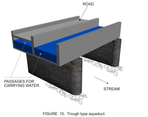
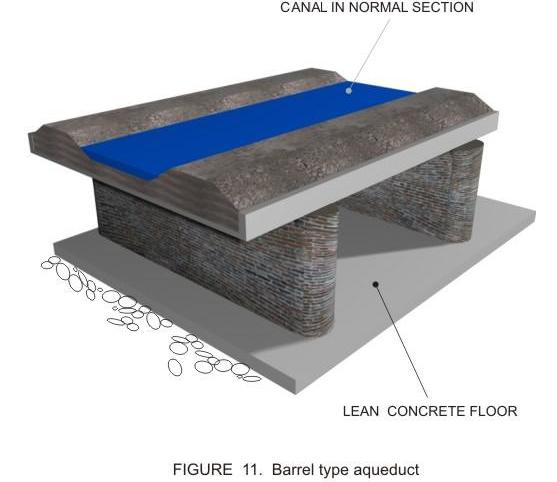
9 Figure 9 shows the relative position of canal with respect to the natural stream where the canal full supply level is below the stream bed level. In general, the solution for all the illustrated conditions possible for conveying an irrigation canal across a natural channel is by providing a water conveying structure which may: (a) Carry the canal over the natural stream; (b) Carry the canal beneath the natural stream; or (c) Carry the canal at the same level of the natural stream. These three broad types of structures are discussed further in this lesson Structures to carry canal water over a natural stream Conveying a canal over a natural watercourse may be accomplished in two ways: (a) Normal canal section is reduced to a rectangular section and carried across the natural stream in the form of a bridge resting on piers and foundations (Figure 10). This type of structure is called a trough type aqueduct. (b) Normal canal section is continued across the natural stream but the stream section is flumed to pass through barrels or rectangular passages (Figure 11). This type is called a barrel type aqueduct.
10
11 Typical sections and plans of a trough type and a barrel type aqueducts are shown in Figures 12 and 13 respectively.
12 For the aqueducts, it may be observed from Figures 12 and 13 that the HFL of the natural stream is lower than the bottom of the trough (or the roof of the barrel). In this case, the flow is not under pressure, that is, it has a free surface exposed to atmospheric pressure. In case the HFL of the natural stream goes above the trough bottom level (TBL) or the barrel roof level (BRL), then the flow in the natural watercourse would be pressured and the sections are modified to form which is known as syphon aqueducts (Figures 14 and 15).
13
14 It may be observed that the trough type aqueduct or syphon aqueduct would be suitable for the canal crossing a larger stream or river, whereas the barrel type is suitable if the natural stream is rather small. The relative economics of the two types has to be established on case to case basis. Further, the following points maybe noted for the two types of aqueducts or siphon aqueducts: Trough type: The canal is flumed to not less than 75 percent of the bed width keeping in view the permissible head loss in the canal.transitions 3:1 on the upstream and 5:1 on the downstream side are provided to join the flumed section to the normal canal section. For the trough-type syphon aqueduct the designer must consider the upward thrust also that might act during high floods in the natural stream when the stream water flows under pressure below the trough base and for worst condition, the canal may be assumed to be dry at that time. The dead weight of the trough may be made more than that of the upward thrust or it may be suitably anchored to the piers in order to may be counteract the uplift condition mentioned.
15 Barrel type: The barrel may be made up of RCC, which could be single or multi-cell, circular or rectangular in cross section. Many of the earlier structures were made of masonry walls and arch roofing. Precast RCC pipes may be economical for small discharges. For barrel-type syphon aqueducts, the barrel is horizontal in the central portion but slopes upwards on the upstream and downstream side at about an inclination of 3H : 1V and 4H : 1V respectively. A self-cleaning velocity of 6m/s and 3m/s is considered while designing RCC and masonry barrels respectively Structures to carry canal water below a natural stream A canal can be conveyed below a natural stream with the help of structures like a super-passage or a siphon. These are exactly opposite in function to that of the aqueducts and siphon aqueducts, which are used to carry the canal water above the natural stream. The natural stream is flumed and made to pass in a trough above the canal. If the canal water flows with a free surface, that is, without touching the bottom of the trough, it is called a super-passage (Figure 16). Else, when the canal passes below the trough as a pressure flow, then it is termed as a syphon or a canal syphon.
16 Instead of a trough, the canal flow may be conveyed below the natural stream using small pre-cast RCC pipes (for small discharges) and rectangular or circular barrels, either in single or multiple cells, may be used (for large discharges), as shown in Figure
17 Structures to carry canal water at the same level as a natural stream A structure in which the water of the stream is allowed to flow into the canal from one side and allowed to leave from the other, known as a level crossing, falls into this category (Figure 18).

18 This type of structure is provided when a canal approaches a large sized drainage with high flood discharges at almost the same level. The flow control is usually provided on either side of the canal and on the outlet side of the drain. As such, this type of arrangement is very similar to canal head-works with a barrage. Advantage may be taken of the flow of the natural drainage to augment the flow of the outgoing canal. The barrage type regulator is kept closed during low flows to head up the water and allows the lean season drainage flow to enter the outgoing canal. During flood seasons, the barrage gates may be opened to allow much of the silt-laden drainage discharge to flow down. Another structure, called an inlet, is sometimes provided which allows the entry of the stream water into the canal through an opening in the canal bank, suitably protected by pitching the bed and sides for a certain distance upstream and downstream of the inlet. If the natural stream water is not utilized in the canal then an outlet, which is an opening on the opposite bank of the canal is provided. The canal bed and sides suitably pitched for protection.

19 3.8.6 Transitions at changes in canal cross-sections A canal cross section may change gradually, in which case suitable flaring of the walls may be made to match the two sections (Figure 19). For more abrupt changes, like a normal canal section being changed to a vertical walled aqueduct, suitable transitions have been designed which would avoid formation of any hydraulic with consequent loss of energy. A typical view of transition of a normal canal bank to a vertical walled flume section is shown in (Figure 20).
.")
20 As may be observed, the banks of the normal canal section are first changed to vertical walls keeping the same canal bed width (BBc). Beyond this, the vertical section is reduced gradually to form a reduced sized flume of width (B fb ). Various formulae have been proposed for deciding the intermediate curve, that is, an equation deciding the width (BBx) at any distance x from the start of the fluming, assuming a length L for the transition. One formula that is commonly used for this kind of transition is the UPIRI method, commonly known as Mitra s transition and is given as follows: BBx = (B c * B f *L ) / (L * B c X (B c B f )) (1) The length L of the transition is assumed to be equal to 2 *(B c B f ). In another type of transition, the vertical curved walls of a normal canal section is both transformed in to vertical walls of a flume as well as its section is reduced gradually, as shown in Figure 20. This results in reduction of the canal bed width from BBc to B fb and the side slopes from M 0 to O. The values for the bed width B x at any length X from the start of the transition and the corresponding side slope m x are given by the following expressions B = B c + X/L [1- (1- X/L) n ] (B c -B f ) (2) m x = m 0 [1 (1- X/L) 1/2 ] (3)
21 Where n = (m 0 ) ½ and the length of transition L, is expressed as L = 2.35 (B c -B f ) m 0 h c (4) Planning and design of canal conveyance structures Though a number of books are available for detailed design of conveyance structures of a canal, as mentioned in the reference list, one may consult the following Bureau of Indian Standard codes for planning, initial designs and construction of these structures. IS: 7784 Code of practice for design of cross drainage works (1) Part General features (Reaffirmed 1987) (2) Part Specific requirements (Reaffirmed 1992) Section1. Aqueducts (3) Part Specific requirements (Reaffirmed 1992) Section2. Superpassage (4) Part Specific requirements (Reaffirmed 1992) Section3. Canal syphons (5) Part Specific requirements (Reaffirmed 1992) Section4. Level crossings (6) Part Specific requirements (Reaffirmed 1992) Section5. Syphon aqueducts IS: Code of practice for subsurface exploration for canals and cross drainage works (Reaffirmed 1990) IS: Code of practice for construction of cross drainage works (Reaffirmed 1992) References Asawa, G L (1996) Irrigation engineering, Second edition, New Age Publications Garg, S K (1996) Irrigation engineering and hydraulic structures, Twelfth Edition, Khanna Publishers
22 IS: Code of practice for subsurface exploration for canals and cross drainage works (Reaffirmed 1990) IS: 7784 Code of practice for design of cross drainage works, Parts 1 to 6 IS: Code of practice for construction of cross drainage works (Reaffirmed 1992) Varshney, R S, Gupta, S C and Gupta, R L (1993) Theory and design of irrigation structures, Volume II, Sixth Edition, Nem Chand Publication
Types of cross drainage works
 Definition: A cross drainage work is a structure carrying the discharge from a natural stream across a canal intercepting the stream. Canal comes across obstructions like rivers, natural drains and other
(b) Discuss in brief shaft spillway with neat sketches. Marks 04. OR Q (2) Explain in brief USBR stilling basin. Marks 08
 Discuss in brief shaft spillway with neat sketches. Marks 04. OR Q (2) Explain in brief USBR stilling basin. Marks 08") (b) Discuss in brief shaft spillway with neat sketches. Marks 04 OR Q (2) Explain in brief USBR stilling basin. Marks 08 Stilling Basins The basins are usually provided with special appurtenances including
(b) Discuss in brief shaft spillway with neat sketches. Marks 04 OR Q (2) Explain in brief USBR stilling basin. Marks 08 Stilling Basins The basins are usually provided with special appurtenances including
Created by Simpo PDF Creator Pro (unregistered version) Asst.Prof.Dr. Jaafar S. Maatooq
 Asst.Prof.Dr. Jaafar S. Maatooq") Lect.No.9 2 nd Semester Barrages, Regulators, Dams 1 of 15 In order to harness the water potential of a river optimally, it is necessary to construct two types of hydraulic structures, as shown in Figure
Lect.No.9 2 nd Semester Barrages, Regulators, Dams 1 of 15 In order to harness the water potential of a river optimally, it is necessary to construct two types of hydraulic structures, as shown in Figure
Highway Drainage 1- Storm Frequency and Runoff 1.1- Runoff Determination
 Highway Drainage Proper drainage is a very important consideration in design of a highway. Inadequate drainage facilities can lead to premature deterioration of the highway and the development of adverse
Chapter 11 Culverts and Bridges
 Chapter 11 Culverts and Bridges Contents 1.0 Introduction... 1 2.0 General Design... 1 2.1 Design Criteria... 1 2.2 Design Flows... 1 2.3 Permitting and Regulations... 1 2.4 Aesthetics and Safety... 2
LOCATION AND DESIGN DIVISION
 VIRGINIA DEPARTMENT OF TRANSPORTATION LOCATION AND DESIGN DIVISION INSTRUCTIONAL AND INFORMATIONAL MEMORANDUM GENERAL SUBJECT: CULVERT DESIGN SPECIFIC SUBJECT: COUNTERSINKING AND LOW FLOW CONSIDERATIONS
Outlet Flow Velocity in Circular Culvert
 Archives of Hydro-Engineering and Environmental Mechanics Vol. 61 (2014), No. 3 4, pp. 193 203 DOI: 10.1515/heem-2015-0013 IBW PAN, ISSN 1231 3726 Outlet Flow Velocity in Circular Culvert Wojciech Szpakowski
DRAINAGE & DESIGN OF DRAINAGE SYSTEM
 Drainage on Highways DRAINAGE & DESIGN OF DRAINAGE SYSTEM P. R.D. Fernando Chartered Engineer B.Sc.(Hons), M.Eng. C.Eng., MIE(SL) Drainage Requirement of Highway Drainage System Introduction Drainage means
Chapter 7. Street Drainage. 7.0 Introduction. 7.1 Function of Streets in the Drainage System. 7.2 Street Classification
 7. Introduction This chapter summarizes methods to evaluate runoff conveyance in various street cross sections and curb types in the Town of Castle Rock and identifies acceptable upper limits of street
PART 3 - STANDARDS FOR SEWERAGE FACILITIES DESIGN OF STORM SEWERS
 PART 3 - STANDARDS FOR SEWERAGE FACILITIES 3.3 - DESIGN OF STORM SEWERS 3.301 Design of Storm Sewers A. General Information B. Investigations and Surveys C. Special Projects 3.302 Design Criteria for Storm
4.2 Discharge measurement by Velocity Area Method (Chitale, 1974)
") 4.2 Discharge measurement by Velocity Area Method (Chitale, 1974) This method comprises measuring the mean velocity V and the flow area 'A' and computing the discharge Q from the continuity equation. The
4.2 Discharge measurement by Velocity Area Method (Chitale, 1974) This method comprises measuring the mean velocity V and the flow area 'A' and computing the discharge Q from the continuity equation. The
Chapter Table of Contents
 Chapter 9 CULVERTS Culverts 9-1 Chapter Table of Contents 9.1 Introduction...9-5 9.2 Policy and Practice...9-5 9.3 Large, Medium, and Small Culverts...9-8 9.4 Sources of Information...9-8 9.5 Culvert
Temporary Watercourse Crossing: Culverts
 Temporary Watercourse Crossing: Culverts DRAINAGE CONTROL TECHNIQUE Low Gradient Velocity Control Short Term Steep Gradient Channel Lining Medium-Long Term Outlet Control Soil Treatment Permanent Symbol
CHECKLIST FOR STREETS, INLETS, AND STORM SEWER DESIGN
 CHECKLIST FOR STREETS, INLETS, I. STREET CLASSIFICATION AND DESIGN CRITERIA A. Determine drainage classification for the roadway section using Table 7-1 or Table 7-2. B. Determine the allowable flow depth
APPENDIX C INLETS. The application and types of storm drainage inlets are presented in detail in this Appendix.
 Storm Drainage 13-C-1 APPENDIX C INLETS 1.0 Introduction The application and types of storm drainage inlets are presented in detail in this Appendix. 2.0 Inlet Locations Inlets are required at locations
Standards for Soil Erosion and Sediment Control in New Jersey May 2012 STANDARD FOR SLOPE PROTECTION STRUCTURES. Definition
 STANDARD FOR SLOPE PROTECTION STRUCTURES Definition Structures to safely conduct surface runoff from the top of a slope to the bottom of the slope. Purpose The purpose of this practice is to convey storm
APPENDIX G HYDRAULIC GRADE LINE
 Storm Drainage 13-G-1 APPENDIX G HYDRAULIC GRADE LINE 1.0 Introduction The hydraulic grade line is used to aid the designer in determining the acceptability of a proposed or evaluation of an existing storm
10.0 Storm Sewer Systems
 October 2003 Chapter 10.0, Storm Sewer Systems Page 1 10.0 Storm Sewer Systems 10.1 Introduction A storm sewer system consists of a system of inlets, pipes, manholes, junctions, cleanouts, outlets, and
Sag Pipe (depressed sewers, or Inverted siphons) Dr. Sataa A. Al-Bayati(10-11)
 Dr. Sataa A. Al-Bayati(10-11)") بسم هللا الرحمن الرحيم Sag Pipe (depressed sewers, or Inverted siphons) Dr. Sataa A. Al-Bayati(10-11) A sewer that drops below the hydraulic gradient to pass under an obstruction, such as a railroad cut,
بسم هللا الرحمن الرحيم Sag Pipe (depressed sewers, or Inverted siphons) Dr. Sataa A. Al-Bayati(10-11) A sewer that drops below the hydraulic gradient to pass under an obstruction, such as a railroad cut,
PARAMETRIC STUDIES OF BOX CULVERTS
 International Journal of Research in Engineering and Science (IJRES) ISSN (Online): 2320-9364, ISSN (Print): 2320-9356 Volume 1 Issue 1 ǁ May. 2013 ǁ PP.58-65 PARAMETRIC STUDIES OF BOX CULVERTS Komal S.Kattimani
Flow Measuring Structures
 Flow Measuring Structures Flow measurement structures are required in irrigation canals in order to facilitate the distribution of water through out the system and to keep account for seepage losses, etc.
1 Doc WRD 13 ( 594 ) GUIDELINES FOR DESGIN ANDS CONSTRUCTION OF WATER COURSES
 GUIDELINES FOR DESGIN ANDS CONSTRUCTION OF WATER COURSES") DRFT STNDRD IN WIDE CIRCULTION SPEED POST Document Dispatch dvice Ref. Date WRD 13/T-53 DEC 2013 TECHNICL COMMITTEE: Canals & Cross Drainage Works Sectional Committee, WRD 13 ------------------------------------------------------------------------------------------------------------------------
DRFT STNDRD IN WIDE CIRCULTION SPEED POST Document Dispatch dvice Ref. Date WRD 13/T-53 DEC 2013 TECHNICL COMMITTEE: Canals & Cross Drainage Works Sectional Committee, WRD 13 ------------------------------------------------------------------------------------------------------------------------
The Islamic University of Gaza- Civil Engineering Department Sanitary Engineering- ECIV 4325 L5. Storm water Management
 The Islamic University of Gaza- Civil Engineering Department Sanitary Engineering- ECIV 4325 L5. Storm water Management Husam Al-Najar Storm water management : Collection System Design principles The Objectives
Learning objectives. Upon successful completion of this lecture, the participants will be able to:
 Solomon Seyoum Learning objectives Upon successful completion of this lecture, the participants will be able to: Describe and perform the required step for designing sewer system networks Outline Design
Design of Sewerage System for Jaffarpur area in Southwest New Delhi
 International Journal of Civil Engineering Research. ISSN 2278-3652 Volume 5, Number 1 (2014), pp. 29-34 Research India Publications http://www.ripublication.com/ijcer.htm Design of Sewerage System for
SECTION 3 DRAINAGE. 3-1 General. 3-2 Drainage Ordinances and Legal Requirements
 SECTION 3 DRAINAGE 3-1 General All Drainage plans for proposed development shall be prepared by a Professional Engineer registered in Virginia, except as noted below. Further, their seal and signature
Stormwater Local Design Manual For Houston County, Georgia
 Stormwater Local Design Manual For Houston County, Georgia Adopted November 15, 2005 TABLE OF CONTENTS 1. FORWARD... 1 2. GENERAL LEVEL OF SERVICE STANDARDS... 2 2.1. DETENTION REQUIREMENTS... 2 2.1.1.
Sri Rama Krishna Institute of Technology Basic civil engineering Unit-2(BUILDING COMPONENTS AND STRUCTURES) 2 mark questions
 2 mark questions") Sri Rama Krishna Institute of Technology Basic civil engineering Unit-2(BUILDING COMPONENTS AND STRUCTURES) 2 mark questions 1. What is masonry? Masonry is defined as construction of building units bonded
Sri Rama Krishna Institute of Technology Basic civil engineering Unit-2(BUILDING COMPONENTS AND STRUCTURES) 2 mark questions 1. What is masonry? Masonry is defined as construction of building units bonded
CHAPTER 12 BRIDGE DECK DRAINAGE SYSTEMS
 OFFICE OF STRUCTURES MANUAL FOR HYDROLOGIC AND HYDRAULIC DESIGN CHAPTER 12 BRIDGE DECK DRAINAGE SYSTEMS APRIL 2011 APRIL 2011 Page 1 Chapter Table of Contents 12.1 Policy... 12-3 12.1.1 Table 1... 12-3
introduction Introduction to Bridge and Tunnel Engineering Characteristics of ideal bridge Ideal location Factors affecting bridge type Classification
 1 introduction Introduction to Bridge and Tunnel Engineering A structure constructed over an obstacle to provide the passage Road bridge movement of traffic See NRS 2045 Cross drainage structure span greater
CONCRETE PIPE AND PORTAL CULVERT HANDBOOK
 CONCRETE PIPE AND PORTAL CULVERT HANDBOOK PIPES, INFRASTRUCTURAL PRODUCTS AND ENGINEERING SOLUTIONS DIVISION PREFACE TO 2006 REVISION Concrete pipes and portal culverts are the most frequently used and
Hydraulic Design of Highway Culverts HDS 5 September 1985
 Hydraulic Design of Highway Culverts HDS 5 September 1985 Welcome to HDS 5 - Hydraulic Design of Highway Culverts Table of Contents Preface Tech Doc U.S. - SI Conversions DISCLAIMER: During the editing
Chapter 7 Ditches and Channels
 Chapter 7 Ditches and Channels TABLE OF CONTENTS CHAPTER 7 - DITCHES AND CHANNELS... 7-1 7.1 Introduction... 7-1 7.2 Design Policy... 7-2 7.2.1 Federal Policy... 7-2 7.2.2 Commonwealth of Virginia Policy...
NORFOLK SOUTHERN CORPORATION UNDERPASS GRADE SEPARATION DESIGN CRITERIA
 NORFOLK SOUTHERN CORPORATION UNDERPASS GRADE SEPARATION DESIGN CRITERIA PURPOSE AND SCOPE These criteria modify and supplement the applicable sections of the AREMA Manual of Recommended Practice in connection
SECTION FACILITY SANITARY SEWERS
 SECTION 22 13 13 FACILITY SANITARY SEWERS PART 1 - GENERAL 1.1 RELATED DOCUMENTS A. Drawings and general provisions of the Contract, including General and Supplementary Conditions and Division 01 Specification
SECTION STORM DRAINAGE DESIGN, GRADING, AND WATER QUALITY TECHNICAL CRITERIA TABLE OF CONTENTS PAGE 402 STORM DRAINAGE DESIGN CRITERIA 400-1
 CITY OF THORNTON Standards and Specifications Revised: October 2012 SECTION 400 - STORM DRAINAGE DESIGN, GRADING, AND WATER QUALITY TECHNICAL CRITERIA TABLE OF CONTENTS PAGE 401 GENERAL PROVISIONS 400-1
MODEL Stormwater Local Design Manual. City of Centerville
 MODEL Stormwater Local Design Manual City of Centerville Adopted December 6, 2005 TABLE OF CONTENTS 1. FORWARD... 1 2. GENERAL LEVEL OF SERVICE STANDARDS... 1 2.1. DETENTION REQUIREMENTS... 1 2.1.1. Discharge
Welded Mesh Gabions and Mattresses River Protection Design Guide Anping County Zhuoda Hardware Mesh Co.,Ltd. Wire Mesh Industrial Zone, Anping
 Welded Mesh Gabions and Mattresses River Protection Design Guide Anping County Zhuoda Hardware Mesh Co.,Ltd. Wire Mesh Industrial Zone, Anping County, Hebei, P. R. China. Tel : 0086-318-7752001 7531068
SECTION 6 STORMWATER AND LAND DRAINAGE
 SECTION 6 STORMWATER AND LAND DRAINAGE Final Version, Approved September 2003 Section 6 and Land Drainage Contents 6.1 PERFORMANCE STANDARDS... 2 6.1.1 General... 2 6.2 MEANS OF COMPLIANCE... 3 6.2.1 General...
Contact the Jurisdictional Engineer for materials allowed by each jurisdiction.
 Design Manual Chapter 3 - Sanitary Sewers 3C - Facility Design 3C-1 Facility Design A. Capacity of Pipe Pipe sizes 15 inches and smaller should carry the peak flow at a depth of no more than 0.67 of the
PAPERWORK REDUCTION ACT A. GENERAL
 U.S. DEPARTMENT OF HOMELAND SECURITY - FEDERAL EMERGENCY MANAGEMENT AGENCY RIVERINE STRUCTURES FORM O.M.B No. 1660-0016 Expires: 12/31/2010 PAPERWORK REDUCTION ACT Public reporting burden for this form
CHAPTER 3 Environmental Guidelines for WATERCOURSE CROSSINGS GOVERNMENT OF NEWFOUNDLAND AND LABRADOR DEPARTMENT OF ENVIRONMENT AND LABOUR
 GOVERNMENT OF NEWFOUNDLAND AND LABRADOR DEPARTMENT OF ENVIRONMENT AND LABOUR CHAPTER 3 Environmental Guidelines for WATERCOURSE CROSSINGS WATER RESOURCES MANAGEMENT DIVISION Water Investigations Section
DESIGN OF SEWER SYSTEMS
 Wastewater Engineering (MSc program) DESIGN OF SEWER SYSTEMS Prepared by Dr.Khaled Zaher Assistant Professor, Public Works Engineering Department, Faculty of Engineering, Cairo University 1. Sewer Materials
CITY OF TROY DESIGN STANDARDS AND CONSTRUCTION SPECIFICATIONS
 CITY OF TROY DESIGN STANDARDS AND CONSTRUCTION SPECIFICATIONS PREPARED BY: F-7587 JANUARY 2010 TABLE OF CONTENTS SECTION 1 SECTION 2 SECTION 3 SECTION 4 SECTION 5 SECTION 6 APPENDIX ROADWAY DESIGN DRAINAGE
4th International Engineering and Construction Conference - July 28, 2006
 4th International Engineering and Construction Conference - July 28, 2006 BOX-JACKING - A USEFUL CONSTRUCTION TOOL By Anthony Lynn, Berkeley Engineering Company, Inc. Box jacking is jacking a large precast
Alberta Bridge Inventory STANDARD BRIDGE & CULVERT COMPONENTS. Standard Bridges. Typical Bridge Components. In Alberta there are about 13,300 bridges.
 STANDARD BRIDGE & CULVERT COMPONENTS Alberta Bridge Inventory In Alberta there are about 13,300 bridges. Types of bridges in Alberta: Standard bridges 3521 (26%) Bridge size culverts 8348 (63%) Major bridges
The City of North Las Vegas (CNLV) does not allow valley gutters to be constructed across streets with right-of-way widths of 80 feet or greater.
 does not allow valley gutters to be constructed across streets with right-of-way widths of 80 feet or greater.") Background The City of rth Las Vegas strives to provide the development community with adequate information to ensure the successful completion of any project in the City. To aid in the submittal of a
Background The City of rth Las Vegas strives to provide the development community with adequate information to ensure the successful completion of any project in the City. To aid in the submittal of a
Chapter 8. Inlets. 8.0 Introduction. 8.1 General
 . Introduction This chapter provides criteria and design guides for evaluating and designing storm sewer inlets in the City of Centennial. The review of all planning submittals will be based on the criteria
f) Culverts in series shall be spaced at least 20 feet between each other. 2.7 C Culverts
 Culverts in series shall be spaced at least 20 feet between each other. 2.7 C Culverts") 2.7 C Culverts 1. General Culverts are intended to safely pass flow under road crossings. Criteria are designed to protect, maintain, and enhance public health, safety, and the environment. Where culverts
2.7 C Culverts 1. General Culverts are intended to safely pass flow under road crossings. Criteria are designed to protect, maintain, and enhance public health, safety, and the environment. Where culverts
iv) Alberta fish weirs
 Alberta fish weirs") Fish passage at culverts in New Zealand 36 iv) Alberta fish weirs The fish weirs used by Alberta Transportation are weir baffles with a partial slot (Figure 16). The best designs from Rajaratnam et al.
Fish passage at culverts in New Zealand 36 iv) Alberta fish weirs The fish weirs used by Alberta Transportation are weir baffles with a partial slot (Figure 16). The best designs from Rajaratnam et al.
SECTION 4 - DESIGN STANDARDS FOR WATER DISTRIBUTION FACILITIES
 SECTION 4 - DESIGN STANDARDS FOR WATER DISTRIBUTION FACILITIES 4.1 GENERAL REQUIREMENTS 4.1.1 Water and fire protection distribution facilities are to be provided solely for the purpose of supplying potable
Table of Contents. July
 Table of Contents 36.1 General... 3 36.1.1 Bridge or Culvert... 3 36.1.2 Box Culvert Size Restrictions... 4 36.1.3 Stage Construction for Box Culverts... 4 36.2 Dead Loads and Earth Pressure... 5 36.3
Section 1000 Culverts and Bridges Table of Contents
 Section 1000 Culverts and Bridges Table of Contents 1001 INTRODUCTION... 1000 1 1002 CULVERT DESIGN STANDARDS... 1000 1 1002.1 CONSTRUCTION MATERIALS... 1000 1 1002.2 MINIMUM CULVERT SIZE... 1000 2 1002.3
3.0 DESIGN CRITERIA FOR SANITARY SEWER FACILITIES
 3.0 DESIGN CRITERIA FOR SANITARY SEWER FACILITIES All sanitary sewers shall be designed in accordance with these Design Standards, LBWD Rules and Regulations, and to accepted engineering principles. In
SPECIFICATION FOR PIPE CULVERT CONSTRUCTION
 SPECIFICATION FOR PIPE CULVERT CONSTRUCTION 1. SCOPE Pipe culverts shall be constructed in accordance with this specification and in conformity with the lines, levels and cross-sections shown on the drawings.
Chapter 9 Hydraulic Structures
 Chapter 9 Hydraulic Structures Contents Structures in Streams... 1 Grade Control Structures... 2 Overview... 2 Simplified Design Procedures for Drop Structures... 4 2.2.1 Introduction... 4 2.2.2 Geometry...
Hancor, Inc. Drainage Handbook Hydraulics 3-1
 Hancor, Inc. Drainage Handbook Hydraulics 3-1 3-0 HYDRAULICS TABLE OF CONTENTS 3-1 Overview of Hydraulic Considerations...3-2 3-2 Design Manning s Value...3-2 3-3 Discharge Curves...3-4 3-3 The Conveyance
Lift irrigation Using man or Animal power Using Mechanical or Electrical Power Flow irrigation a)inundation Irrigation b) Perennial Irrigation Direct
inundation Irrigation b) Perennial Irrigation Direct") Lift irrigation Using man or Animal power Using Mechanical or Electrical Power Flow irrigation a)inundation Irrigation b) Perennial Irrigation Direct irrigation Storage irrigation a)flow irrigation system:
Lift irrigation Using man or Animal power Using Mechanical or Electrical Power Flow irrigation a)inundation Irrigation b) Perennial Irrigation Direct irrigation Storage irrigation a)flow irrigation system:
CIVIL BREADTH Exam Specifications
 NCEES Principles and Practice of Engineering Examination CIVIL BREADTH and STRUCTURAL DEPTH Exam Specifications Effective Beginning with the April 2015 Examinations The civil exam is a breadth and depth
Module 4. Hydraulic structures for flow diversion and storage. Version 2 CE IIT, Kharagpur
 Module 4 Hydraulic structures for flow diversion and storage Lesson 1 Structures for Flow Diversion Investigation Planning and Layout Instructional objectives On completion of this lesson, the student
SPECIFICATIONS FOR THE INSTALLATION OF REDUCED PRESSURE BACKFLOW PREVENTERS AND CONCRETE VAULTS FOR METERS 4 AND LARGER
 SPECIFICATIONS FOR THE INSTALLATION OF REDUCED PRESSURE BACKFLOW PREVENTERS AND CONCRETE VAULTS FOR METERS 4 AND LARGER Updated January 2018 RP-2 Installation Specifications 1. In W.H.U.D s service area
ROLES AND RESPONSIBILITIES Small Pond Approval. SWM MD-378 Pond Checklist Training 10/17/07. Exemptions EMBANKMENT HEIGHT. Height of Dam Weir Wall
 SWM MD-378 Pond Checklist Training 10/17/07 Ken Wolfe Warren Johnson USDA, NRCS Frederick, Maryland ROLES AND RESPONSIBILITIES Small Pond Approval MDE, WMA, Dam Safety Division Authority (COMAR 26.17.04.03)
City of Saint John. Storm Drainage Design Criteria Manual
 Storm Drainage Design Criteria Manual March 7, 2016 LIST OF 2016 REVISIONS PAGES SECTION TITLE iii, iv, v, vi All Table of Contents 31-35 3 SUBMISSION REQUIREMENTS March 7, 2016 Page i DISCLAIMER The material
Box Culverts. Easy to install, suitable for very shallow or deep fill, ideal for use in a wide variety of civil engineering applications.
 Box Culverts Box Culverts Easy to install, suitable for very shallow or deep fill, ideal for use in a wide variety of civil engineering applications. 2 3 System Overview Forterra is one of the largest
DEPARTMENT OF THE ARMY EM U.S. Army Corps of Engineers CECW-ED Washington, DC
 DEPARTMENT OF THE ARMY EM 1110-2-2007 U.S. Army Corps of Engineers CECW-ED Washington, DC 20314-1000 Manual No. 1110-2-2007 30 April 1995 Engineering and Design STRUCTURAL DESIGN OF CONCRETE LINED FLOOD
Location Drainage Study
 Location Drainage Study PROJECT ROUTE: LIMITS: MUNICIPALITY/COUNTY: JOB NUMBER: IL 47 at Burlington Road 750ft NW to 750ft SE of IL 47(Burlington), & 1000ft S to 1000ft N of Burlington (IL47) Kane County
DESIGN OF FLYOVER TRANSVERSE VERTICALLY BY USING HYDRAULIC JACK
 DESIGN OF FLYOVER TRANSVERSE VERTICALLY BY USING HYDRAULIC JACK M. Hari Sathish Kumar 1, K. S. Binitha 2, K. Balaji 3 1,2Assistant Professor, Department of Civil Engineering, PERI Institute of Technology,
Best Practices for Building High-Performance Resource Roads. Road Drainage. Developed by: The Roads and Infrastructure Group
 Best Practices for Building High-Performance Resource Roads Road Drainage Developed by: The Roads and Infrastructure Group THIS GUIDE IS INTENDED FOR EQUIPMENT OPERATORS CONSTRUCTION CONTRACTORS FIELD
MICHIGAN DESIGN MANUAL ROAD DESIGN CHAPTER 4 INDEX DRAINAGE
 CHAPTER 4 INDEX DRAINAGE Supplement to Chapter 4 4.01 GENERAL INFORMATION 4.01.01 References 4.01.03 General Procedures 4.02 STORM SEWER DESIGN 4.02.15 Sewer Bulkheads 4.02.18 Storm Sewers Under Structures
Types of Inspections. Prior to Inspection. Types of Inspections. Typical Inspection Equipment. Embankment Dams
 BIA Summer Water Resources Training Dam Safety Inspections Part 4 - Inspections July 28, 2012 Presented by Michael Johnson, Ph.D., P.E. Types of Inspections Periodic Inspections A comprehensive visual
Water Measurement. Presentation by. L. Niel Allen Extension Irrigation Specialist Utah State University
 Water Measurement Presentation by L. Niel Allen Extension Irrigation Specialist Utah State University to Utah State Engineer s Office Division of Water Rights Salt Lake City, Utah December 11, 2013 Introduction
North Domingo Baca Extension at Barstow
 Modeling Report April 5, 2001 North Domingo Baca Extension at Barstow Prepared for the Albuquerque Metropolitan Arroyo Flood Control Authority Julie Coonrod, Ph.D., P.E. Department of Civil Engineering
15. Detailed, specific REVISION STATEMENT on plan and or letter attached to each set of plans (for permit revisions only)
") Form A2 DEPARTMENT OF PUBLIC WORKS 1526 East Forrest Ave. Suite 400 East Point, Georgia 30344 (404) 270-7116 FAX (404) 270-7214 www.eastpointcity.gov LAND DEVELOPMENT PERMIT CHECKLIST Project Name: Tax
Form A2 DEPARTMENT OF PUBLIC WORKS 1526 East Forrest Ave. Suite 400 East Point, Georgia 30344 (404) 270-7116 FAX (404) 270-7214 www.eastpointcity.gov LAND DEVELOPMENT PERMIT CHECKLIST Project Name: Tax
Sub. Code:
 (ISO/IEC - 700-005 Certified) Model Answer: Summer 07 Sub. Code: 750 Important Instructions to examiners: ) The answers should be examined by key words and not as word-to-word as given in the model answer
Highway Engineering. 3 _ 2/2 Lecture/Laboratory Hours
 COURSE OUTLINE CIV216 Course Number Highway Engineering Course Title 3 _ 2/2 Credits Lecture/Laboratory Hours COURSE DESCRIPTION Explores the planning, design, construction, and characteristics of highways
16. Design of Pipeline Structures.
 16. Design of Pipeline Structures. a. General. 1) The following guidelines are for the design of structures for water and sewer pipelines including structural concrete and miscellaneous metals design.
Municipal Stormwater Ordinances Summary Table
 APPENDIX F Municipal Ordinances Summary Table Municipality Abington Bryn Athyn Borough Hatboro Borough Ordinance, SALDO Runoff equals pre post Erosion Sediment Control Water Quality Requirements Any which
Standards for Soil Erosion and Sediment Control in New Jersey May 2012 STANDARD FOR RIPRAP. Conditions Where Practice Applies
 STANDARD FOR RIPRAP Definition A layer of loose rock, aggregate, bagged concrete, gabions, or concrete revetment blocks placed over an erodible soil surface. Purpose The purpose of riprap is to protect
highways, drainage, runoff, surface, sub-surface, systems Carrier pipe
 SCI LECTURE PAPERS SERIES HIGHWAY DRAINAGE SYSTEMS Santi V Santhalingam Highways Agency, Room 4/41, St. Christopher House Southwark Street, London SE1 0TE Telephone +44 (0) 171 921 4954 Fax +44 (0) 171
ABERDEEN CITY SUSTAINABLE DRAINAGE SYSTEMS (SUDS) AND FLOOD DEFENCES
 AND FLOOD DEFENCES") ABERDEEN CITY SUSTAINABLE DRAINAGE SYSTEMS (SUDS) AND FLOOD DEFENCES Countesswells Avenue, Retention Pond A retention ponds function is for water attenuation (storing and slow release) and treatment. The
ABERDEEN CITY SUSTAINABLE DRAINAGE SYSTEMS (SUDS) AND FLOOD DEFENCES Countesswells Avenue, Retention Pond A retention ponds function is for water attenuation (storing and slow release) and treatment. The
Design of Small Hydro Power Project on Main Tirhut Canal, Champaran, Bihar, India
 OPEN ACCESS Int. Res. J. of Science & Engineering, 2015; Vol. 3 (3): 125-130 ISSN: 2322-0015 RESEARCH REPORT Design of Small Hydro Power Project on Main Tirhut Canal, Champaran, Bihar, India Kumar Manish
Article 20: Erosion Control and Stormwater Management
 Article 20: Erosion Control and Stormwater Management Section 360: Purpose, Scope of Authority, Performance Guarantee and Approvals A. Purpose. The purpose of this document is to set forth minimum requirements
Standards for Soil Erosion and Sediment Control in New Jersey May 2012 STANDARD FOR GRASSED WATERWAYS. Definition. Purpose
 STANDARD FOR GRASSED WATERWAYS Definition A natural or constructed watercourse shaped or graded in earth materials and stabilized with suitable vegetation for the safe conveyance of runoff water. Purpose
DESIGN MANUAL FOR CONCRETE PIPE OUTFALL SEWERS P.I.P.E.S
 DESIGN MANUAL FOR CONCRETE PIPE OUTFALL SEWERS P.I.P.E.S Pipes, Infrastructural Products and Engineering Solutions Division PREFACE Research on sewer corrosion commenced at the CSIR in 1950, supported
3.0 STORM DRAINAGE SYSTEM DESIGN
 SPALDING COUNTY, GEORGIA CHAPTER 3 3.0 STORM DRAINAGE SYSTEM DESIGN... 3-1 3.1 OVERVIEW... 3-1 3.1.1 INTRODUCTION... 3-1 3.1.2 DRAINAGE SYSTEM COMPONENTS... 3-1 3.1.3 INLET AND STORM DRAIN PIPE DESIGN...
UNIT III Earthwork Estimation & Reinforcement Estimation
 SIDDHARTH GROUP OF INSTITUTIONS :: PUTTUR Siddharth Nagar, Narayanavanam Road 517583 QUESTION BANK (DESCRIPTIVE) Subject with Code : ECV(13A01605) Year & Sem: IV-B.Tech & I-Sem Course & Branch: B.Tech
STREAMBANK RESTORATION DESIGN
 STREAMBANK RESTORATION DESIGN WITH VINYL SHEET PILE GRADE CONTROL STRUCTURES BRUCE M. PHILLIPS, M.S., P.E. ABSTRACT Grade control structures are an effective channel stabilization measure which can eliminate
LEADING SOLUTION PROVIDER FOR OVERFILLED PRECAST ARCH BRIDGES
 LEADING SOLUTION PROVIDER FOR OVERFILLED PRECAST ARCH BRIDGES Suppliers Number: 221198 4900092 FS 606596 0086 BEBO Arch System Leading Solution Providers The BEBO Arch System is a standardised patented
Chapter 10 CULVERTS SOUTH DAKOTA DRAINAGE MANUAL
 Chapter 10 CULVERTS SOUTH DAKOTA DRAINAGE MANUAL October 2011 Table of Contents Section Page 10.1 INTRODUCTION...10-1 10.1.1 Definition...10-1 10.1.2 Purpose...10-1 10.1.3 Concepts...10-1 10.1.4 Symbols...10-2
EXPERIMENTAL STUDY OF EFFECT OF END SILL ON STILLING BASIN PERFORMANCE
 EXPERIMENTAL STUDY OF EFFECT OF END SILL ON STILLING BASIN PERFORMANCE H.L.Tiwari Department of Civil Engineering, Maulana Azad National Institute of Technology, Bhopal, Madhya Pradesh INDIA Arun Goel
Understanding. Hydraulics. palgrave macmillan. Les Hamill. University of Plymouth THIRD EDITION
 Understanding Hydraulics THIRD EDITION Les Hamill Senior Lecturer in Civil Engineering, School of Marine Science and Engineering, University of Plymouth palgrave macmillan Preface to third edition Acknowledgements
DESIGNING AND CONSTRUCTION OF T-WALL RETAINING WALL SYSTEM
 Istanbul Bridge Conference August 11-13, 2014 Istanbul, Turkey DESIGNING AND CONSTRUCTION OF T-WALL RETAINING WALL SYSTEM T. C. NEEL and K.BOZKURT ABSTRACT This work shall consist of the design, manufacture
Chapter 7 Water Conveying Conduits
 Chapter 7 Water Conveying Conduits After the capacity of the water conduit system is known, the type and size of the supply and drainage conduits have to be determined, which is an iterative process. Various
CITY UTILITIES DESIGN STANDARDS MANUAL
 CITY UTILITIES DESIGN STANDARDS MANUAL () September 2017 Page Chapter 1 Acronyms and Definitions 1.01 Purpose 1 1.02 Acronyms 1 1.03 Definitions 3 Chapter 2 Introduction 2.01 Purpose 1 2.02 Applicability
Reinforced Concrete Microtunnelling Pipe Designed for Project Conditions and MTBM Machines
 Reinforced Concrete Microtunnelling Pipe Designed for Project Conditions and MTBM Machines Maged Mekhael, Munro Ltd. TRENCHLESS TECHNOLOGY ROADSHOW May 28-29, 2014 Scotiabank Convention Centre, Niagara
Model Lift Irrigation Scheme
 Model Lift Irrigation Scheme (Lecture notes by Dr.S.S.Rao) Contents 1. Introduction... 2 2. Guideline lines for small lift irrigation schemes.... 3 2.1. Lift irrigation on surface water... 3 2.1.1 Size
SECTION 11: REGULATORY FLOODWAYS
 SECTION 11: REGULATORY FLOODWAYS Contents 11.1. The Floodway... 11-2 11.1.1. The floodway concept... 11-2 11.1.2. Floodway map... 11-2 11.1.3. Floodway permitting... 11-3 11.1.4. Changing the floodway...
Tolerances for Concrete Construction. Tolerances for Concrete Construction. Tolerance 6/16/2015
 Tolerances for Concrete Construction Thomas J Downs P.E., FACI President Forensic Experts Minneapolis, MN What is it? Tolerances for Concrete Construction When did we start this anyway? Who said we needed