Monitoring Well Installation Report
|
|
|
- Clarence Jenkins
- 6 years ago
- Views:
Transcription

1 Monitoring Well Installation Report Xcel Energy February 1, 2016, Morgan County, Colorado
2 Xcel Energy Monitoring Well Installation Report Table of Contents 1.0 Introduction Background Information Field and Laboratory Methods Borehole Drilling Soil Samples Geotechnical Analysis Well Construction Well Development Well Survey Groundwater Level Measurement and Aquifer (Slug) Testing Decontamination of Field Equipment Field and Laboratory Results Borehole Drilling Soil Samples Geotechnical Analysis Well Construction Well Development Well Survey Groundwater Level Measurement and Aquifer (Slug) Testing References i
3 Xcel Energy Monitoring Well Installation Report List of Tables Table 1. Summary of Geotechnical Testing Results... 7 Table 2. Well Construction Details for Groundwater Monitoring Wells PNMW-12, PNMW-13, PNMW- 14 at... 9 Table 3. Field Water Quality After Well Development Table 4. Slug Testing Results List of Figures Figure 1. Vicinity Map for... 2 Figure 2. Well Location Map, Pawnee... 3 List of Appendices A. Borehole Logs B. Well Construction Diagrams C. Geotechnical Analysis Laboratory Reports D. State Well Permits E. Slug Test Analyses ii
4 Xcel Energy Monitoring Well Installation Report Table of Abbreviations and Acronyms Abbreviation AMSL BGS BTOC CCR cm/sec HP Geotech µs/cm NTU PSCo TOC USCS Definition above mean sea level below ground surface below top of casing Coal Combustion Residuals centimeter per second Hepworth-Pawlak Geotechnical, Inc. microsiemens per centimeter nephelometric turbidity unit Public Service Company of Colorado top of casing Unified Soil Classification System iii
5 Xcel Energy Monitoring Well Installation Report 1.0 Introduction The purpose of this Monitoring Well Installation Report is to document details pertaining to the drilling, construction, and development of three groundwater monitoring wells installed at the Xcel Energy Pawnee Generating Station () in Morgan County, Colorado (Figure 1). The groundwater monitoring system is intended to support compliance with the U.S. Environmental Protection Agency s final Coal Combustion Residuals (CCR) Rule (40 CFR Parts 257 and 261). has one CCR landfill unit subject to the CCR Rule. The drilling and well installation was performed in accordance with the State of Colorado Water Well Construction Rules (2 Code of Colorado Regulations 402-2). HDR was contracted to locate, design, permit and oversee the installation of the three groundwater monitoring wells at. HDR retained Hepworth-Pawlak Geotechnical, Inc. (HP Geotech) to provide on-site drilling services, while HDR provided oversight of the drilling, well installation, and development. All on-site personnel completed the site-specific safety training. Additionally, daily safety briefs were conducted by the on-site project team prior to commencing work. The training and safety briefs were documented in accordance with the PSCo CCR Rule Compliance Health & Safety Plan. 2.0 Background Information Prior hydrogeologic and geotechnical investigations have been conducted at Pawnee as documented in reports identified and summarized in the Pawnee Monitoring Well Installation Plan (HDR, 2015). Dune sand deposits are present at the CCR landfill, which overlie a fine-grained soil (weathered Pierre Shale) and Pierre Shale Formation bedrock. Groundwater is generally found at the bedrock and residual soil contact. Dune sands in the CCR landfill area overlay the residual soil and generally do not contain water; however, perched water-table conditions can be present in localized areas underlain by low-permeability material (PSCo, 2015). Regional groundwater flow is generally to the northeast across the site towards the South Platte River; however, a bedrock high, trending northwest to southeast, is present beneath the landfill area, resulting in a radial flow away from the landfill on the eastern side (PSCo, 2015; shown in Figure 2). The three new monitoring wells installed at (PNMW-12, -13, -14; Figure 2) were sited based on monitoring requirements in the CCR Rule, facility design, and existing hydrogeologic data for the vicinity, as described in the Groundwater Monitoring System Certification (HDR, 2015). 1

6 Xcel Energy Monitoring Well Installation Report Figure 1. Vicinity Map for 2

7 Xcel Energy Monitoring Well Installation Report Figure 2. Well Location Map, 3
8 Xcel Energy Monitoring Well Installation Report 3.0 Field and Laboratory Methods 3.1 Borehole Drilling The boreholes for each well were drilled by HP Geotech using a hollow stem auger drilling method between November 16 and 18, Utility locations were identified prior to beginning drilling operations. However, to ensure the absence of any buried utilities, the driller advanced soil borings from the ground surface to a minimum depth of 8 feet using a pot-holing technique prior to drilling. The borehole was then advanced using the hollow stem auger drilling method with a CME-55 drill rig. The nominal borehole diameter was 6 inches to accommodate construction of 2-inch diameter wells. Similar to the previously constructed groundwater monitoring wells on site 1, screen depth was targeted for placement above the Pierre Shale bedrock within the dune deposits. Therefore, as described in the Monitoring Well Installation Plan (HDR, 2015), all boreholes were drilled to the top of the Pierre Shale or to a depth of at least 10 feet below the water table, whichever was shallower. This resulted in boreholes with total depths of 50 and 70 feet below ground surface (bgs), as further described in Section 4.3. An HDR geologist was present during drilling operations to collect samples and log the subsurface material, in addition to overseeing site safety and proper well construction. Soil samples from boreholes were collected in plastic bags and logged every 5 feet by the field geologist during drilling to document lithologic soil characteristics. The geologist visually classified soil type, consistency/relative density, color, and water content in accordance with the Unified Soil Classification System (USCS) as well as grain size, mineralogy, sorting, rounding, hardness, and matrix/clast support, among other textural properties. Samples were placed in sample bags labeled with the borehole identification and depth interval. One undisturbed soil sample from each well was collected within the well screen depth interval and submitted to a lab for hydraulic properties analysis, as described below in Section 3.2. Boring logs for each borehole are provided in Appendix A. Soil cuttings, fluids, and potholing slurry generated during drilling were transported to and disposed of at the existing evaporation pond within the on-site ash landfill. Drilling equipment was decontaminated with potable water before moving to the next bore hole. 3.2 Soil Samples Geotechnical Analysis Soils were logged from the cutting returns during drilling and classified based on the USCS. During drilling, one undisturbed soil sample was obtained from each borehole at a depth coinciding with the interval of the well screen depth. An 18-inch long California Modified Style Split-Spoon Sampler was 1 The existing wells on site are screened above the Pierre Shale bedrock. The screened intervals at these existing wells capture the higher of either the residual soil/dune sand contact or the residual soil/weathered bedrock, up to the maximum historic groundwater elevation. This screening interval intercepts potential seepage from the landfill through either the dune sand or transition zone bedrock (PSCo, 2015). This approach has worked well for the groundwater monitoring program conducted on the site and wells for this project were therefore similarly constructed. 4
9 Xcel Energy Monitoring Well Installation Report used to collect the undisturbed core of sediment. The undisturbed soil samples (one from each well) were submitted to HP Geotech for analysis of the following parameters: Grain-size: Sieve and Hydrometer (ASTM D421/422) Total Porosity (SW9) Bulk Density (ASTM D2937) Moisture Content (ASTM D2216) Specific Gravity (ASTM D854) Analysis was completed in accordance with the method for grain-size analysis using sieve and hydrometer described in ASTM D421/422 (ASTM D421-85, 1998 and ASTM D422-63, 2007). Chain of custody documentation is provided in Appendix B. 3.3 Well Construction Once the target drilling depth was reached at each location, 2-inch diameter, Schedule 40 PVC casing and well screens (0.010-inch slots) were assembled and lowered into each borehole. Approximately 30 feet of screen was installed in PNMW-12, -13, and -14. After pvc casing and screen placement in the borehole, the filter pack sand and the bentonite pellet seal were placed via gravity feed from the surface into the annular space. The filter pack consisted of (sieve size) washed silica sand emplaced from the bottom of the hole to approximately 5 feet above the well screen. An annular seal of bentonite pellets was placed to 5 feet above the top of the filter pack and hydrated for 12 hours after placement. HP Geotech then used a tremie pipe to place bentonite grout above the bentonite seal to within approximately two feet of the surface. An annular surface seal consisting of neat cement was installed from the top of the bentonite grout to the surface. All wells were finished with a 2-foot-by-2-foot concrete pad. Each well included between 3 and 4 feet of PVC stick-up. Three bollards were installed at PNMW-12, and no bollards were installed at PNMW-13 or PNMW-14. Each well was secured with a protective steel casing and lock. Well construction is further described in Section Well Development Wells were developed over several days to improve hydraulic connectivity in the area immediately surrounding the well and remove any fluids introduced during drilling. Well development involves removing as much of the introduced drilling fluids, cuttings, and particulates from within and adjacent to the well as possible. Development did not begin until at least 12 hours after the wells had been grouted to ensure grout had sufficiently set. Wells were developed by surge blocking and pumping. This method involves moving a surge block up and down the well screen and casing which alternately forces water in and out of the screen, loosens sediment, and draws fine-grained materials into the well, then removing the purge water and fine sediment from the well using a pump. The duration of development; initial water level; well depth; method; and field parameter measurements of ph, specific conductance, temperature, and turbidity were recorded on the 5
10 Xcel Energy Monitoring Well Installation Report development record for each well. The amount of purge water removed from each well was estimated in the field. Field parameters were recorded approximately every 5 minutes of discharge and checked more often for wells with slow recharge. Well development continued until field parameters stabilized. Stabilized field parameters were defined as three consecutive readings where temperatures were within 1 C, ph readings were within 0.2 standard units, and conductivity within 10 percent, and turbidity values were less than 10 nephelometric turbidity units (NTU). The field manager was notified when field parameters stabilized, and development ceased when the water was visually free of suspended solids. Purge water was placed into drums and/or buckets and disposed of at the CCR landfill. All three wells took considerable time to develop, between four and six days. All non-dedicated down-well equipment used during development was decontaminated. 3.5 Well Survey Surveying of the monitoring wells was performed by professional surveyor, Edward-James Surveying, Inc. after well completion. The surveyor recorded elevations of the top of PVC casing (point at notch on the north side of the casing top) and ground surface using a level loop. The northing and easting coordinates of the wells were also surveyed. 3.6 Groundwater Level Measurement and Aquifer (Slug) Testing HDR performed slug tests on monitoring wells PNMW-12, PNMW-13, and PNMW-14 on December 9, 2015 to calculate hydraulic conductivity for the shallow unconfined aquifer. A 1.5-inch diameter by 2.7-foot long watertight slug was used. Given a 2-inch diameter well, an expected slug displacement of 1.52 feet is estimated for the slug. A transducer was suspended on a communications cable near the bottom of the well, and recorded water level measurements at 1-second intervals. Both slug-in and slug-out tests were performed. Slug-in tests were completed by dropping the slug into the water column as quickly as possible, and measuring the falling water level that followed. Slug-out tests were completed after each slug-in test by removing the slug from the water column as quickly as possible and measuring the rising water level that followed. Well-specific testing details are summarized below: PNMW-12: One slug-in and one slug-out test were performed on December 9, The depth to water in the well was feet below top of casing. With a well screen interval of feet bgs and a casing stick-up of 3.86 feet, 9.14 feet of the well screen was exposed to the vadose zone. PNMW-13: One slug-in and one slug-out test were performed on December 9, The depth to water in the well was feet below top of casing. With a well screen interval of feet bgs and a casing stick-up of 3.89 feet, feet of the well screen was exposed to the vadose zone. PNMW-14: One slug-in and one slug-out test were performed on December 9, The depth to water in the well was feet below top of casing. With a well screen interval of feet bgs and a casing stick-up of 4.00 feet, feet of the well screen was exposed to the vadose zone. 6
11 Xcel Energy Monitoring Well Installation Report Slug test data was downloaded from the Rugged Reader at the end of each working day and saved locally to a laptop. All non-dedicated down-well equipment used during slug testing was decontaminated. 3.7 Decontamination of Field Equipment Field instrumentation (such as interface probes or water quality meters) was decontaminated between sample locations by rinsing with an Alconox/distilled water solution followed by a potable water rinse and a final rinse with deionized water. 4.0 Field and Laboratory Results 4.1 Borehole Drilling Boring logs for each borehole are provided in Appendix A. Soil cuttings from the borehole samples, which consisted primarily of fine to medium grained sand and silty sand, were dry at all three wells from the ground surface to approximately 50 to 55 feet. At two boreholes, PNMW-12 and -13, silty sand and sand, respectively, were encountered with shale at approximately 45 to 50 feet, respectively. This was presumed to be the top of the Pierre Shale formation. Moist sediment was encountered at only one boring, well PNMW-14, during drilling, at a depth of approximately 55 feet bgs. Shale was encountered at PNMW-14 at approximately 69 feet bgs. 4.2 Soil Samples Geotechnical Analysis The undisturbed soil samples collected from the well screen depth interval of each borehole were analyzed for grain size and porosity by HP Geotech, and are summarized in Table 1. The soils laboratory results are presented in Appendix B. Laboratory results show the wells are screened in sandy silt, with porosities between 32 and 40 percent, which is consistent with the silty sand material noted in the drilling logs. Well I.D. Table 1. Summary of Geotechnical Testing Results Sample Depth (ft BGS) Gradation Gravel (%) Sand (%) Silt and Clay (%) Total Porosity (%) Moisture Content (%) PNMW PNMW PNMW Note: BGS = below ground surface 7
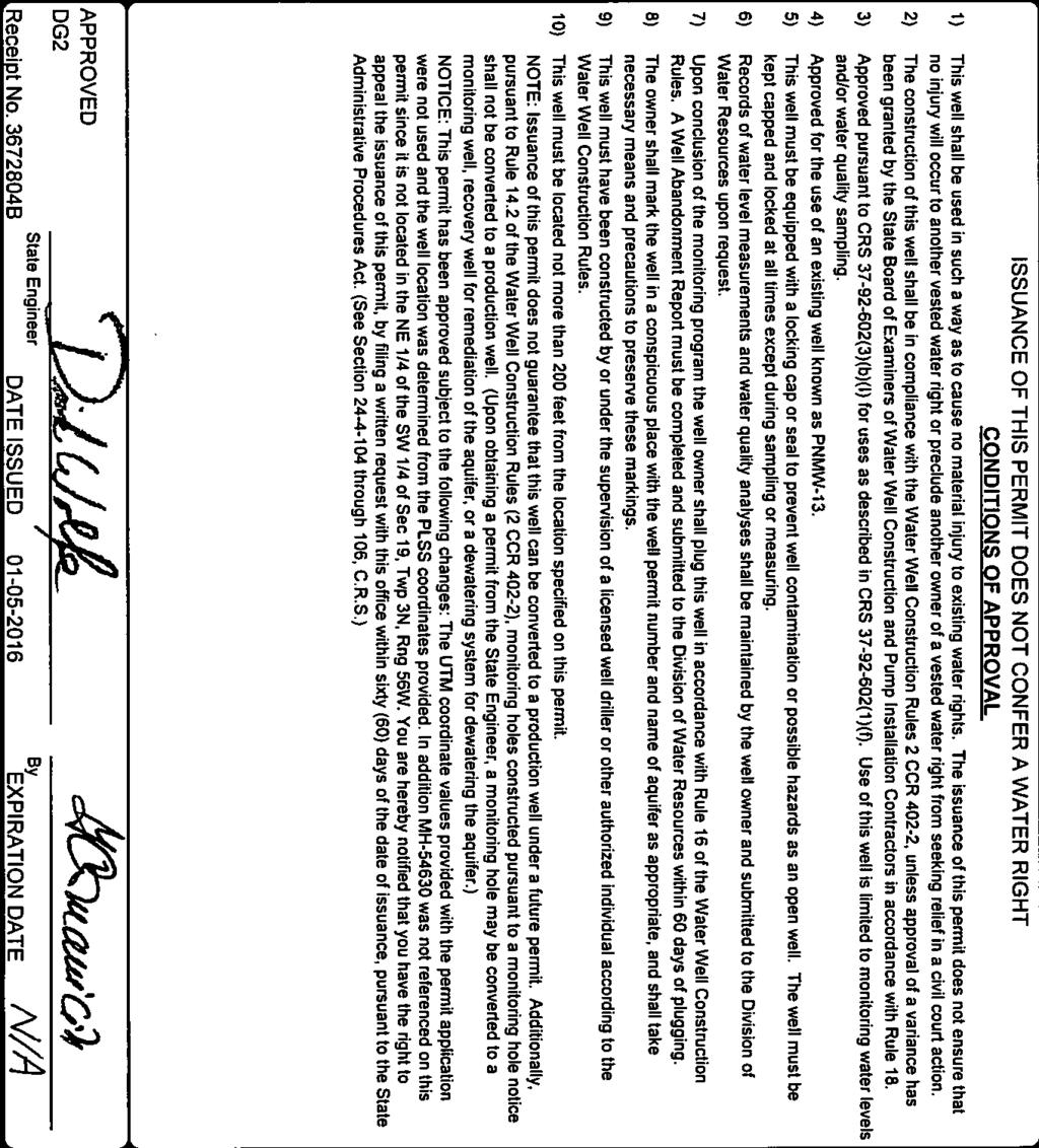
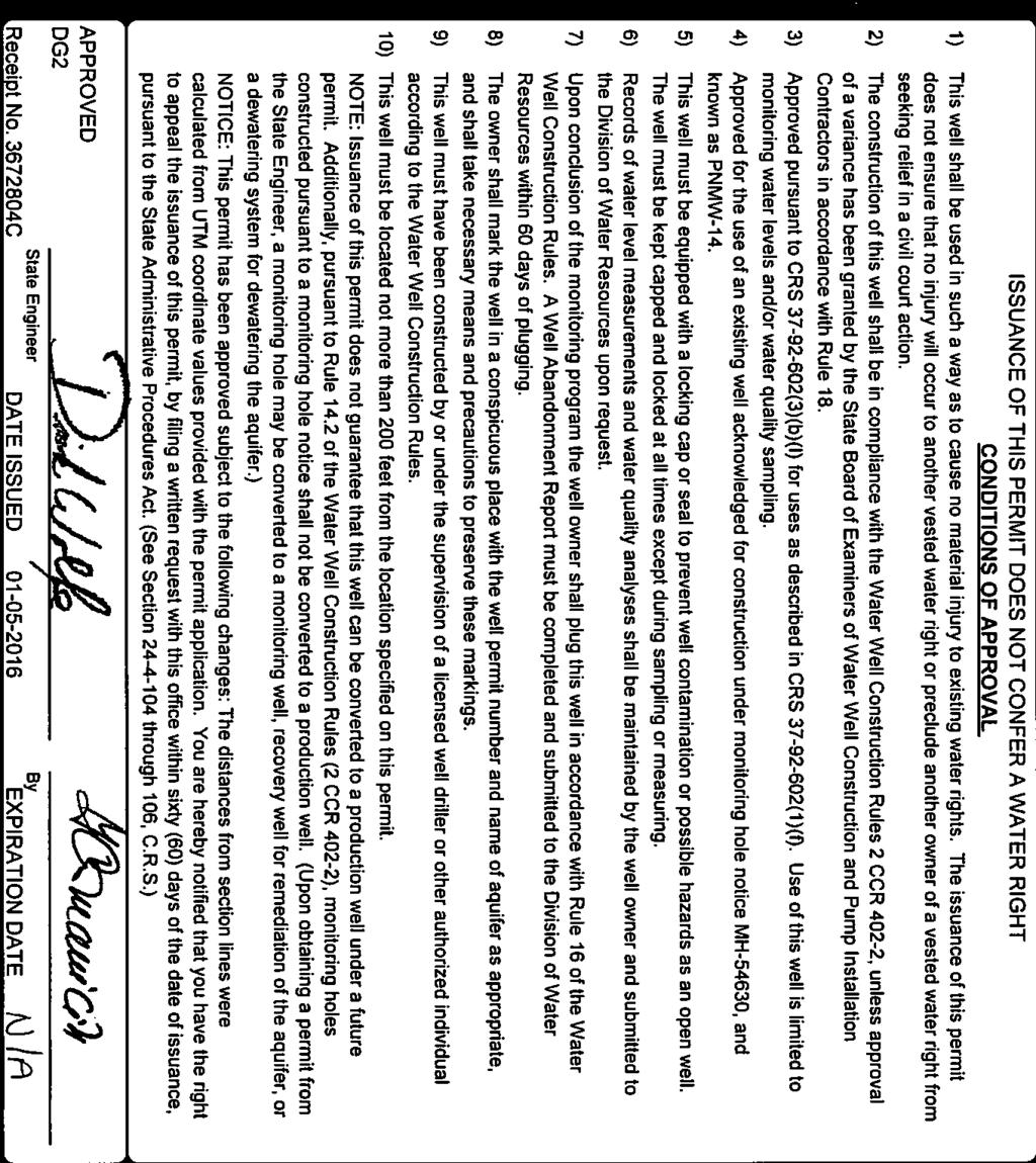
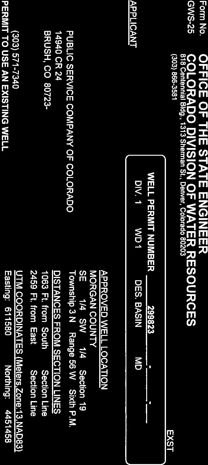
12 Xcel Energy Monitoring Well Installation Report 4.3 Well Construction A diagram for each well documenting well construction is provided in Appendix C. Approximately 30 feet of screen was installed in each well. The screen was placed from approximately 20 to 50 feet bgs in wells PNMW-12 and PNMW-13, directly above the Pierre Shale formation. In well PNMW-14, the water table was encountered at approximately 55 feet bgs during drilling, and shale was encountered at approximately 69 feet bgs. The screen was placed from approximately 40 to 70 bgs at PNMW-14. Well construction details for all three wells are summarized in Table 2. State well construction permits are included in Appendix D. 8
13 Xcel Energy Monitoring Well Installation Report Table 2. Well Construction Details for Groundwater Monitoring Wells PNMW-12, PNMW-13, PNMW-14 at Well I.D. PNMW- 12 PNMW- 13 PNMW- 14 Northing (State Plane, NAD 1983 UTM Zone 13 N meters) Easting (State Plane, NAD 1983 UTM Zone 13 N meters) Elevation TOC (feet AMSL) Well Total Depth (feet BGS) Depth of Screen Interval (feet BGS) Well Stickup (feet) Notes: TOC = top of casing BTOC = below top of casing BGS = below ground surface AMSL = above mean sea level Casing Type 2-inch Sch. 40 PVC 2-inch Sch. 40 PVC 2-inch Sch. 40 PVC Depth to Water (feet BTOC) Static Water Level (feet AMSL)
14 Xcel Energy Monitoring Well Installation Report 4.4 Well Development Wells were developed over several weeks (November 19 through December 7, 2015). Development was considered relatively difficult for all three wells, due primarily to high turbidity readings and relatively slow recharge rates. On December 4, 2015, parameters stabilized after approximately 70 gallons of water was removed from PNMW-12. On December 7, 2015 the field parameters stabilized at PNMW-13 after 64 gallons of water had been removed. Development of PNMW-14 was completed on December 4, 2015 after 127 gallons of water had been removed. Water quality parameters measured in the field after development are noted in Table 3. Well I.D. Table 3. Field Water Quality After Well Development Conductivity (µs/cm) ph Temperature (degrees C) Turbidity (NTU) PNMW PNMW PNMW Notes: µs/cm = microsiemens per centimeter NTU = nephelometric turbidity unit 4.5 Well Survey Survey coordinates and elevations are provided in Table Groundwater Level Measurement and Aquifer (Slug) Testing All slug-in and slug-out tests were analyzed using the Dagan (1978) slug test solution for unconfined aquifers, and implemented using Aqtesolv v4.5. Each well screen intersected the water table (i.e., was partially submerged) during the slug testing. An effective casing radius correction was applied using Aqtesolv to account for drainage to and from the filter pack. For this correction, a well radius of 0.25 foot was used and an equipment radius of foot was specified for the transducer cable. The aquifer at each location was represented with the following estimates of saturated thickness: feet (MW-12), feet (MW-13), and feet (MW-14). An anisotropy ratio of 1 (unitless) was assigned to the aquifer at each well location. Initial displacement created by the slug, and hydraulic conductivity results for the slug testing are shown in Table 4. In all but one test, the initial displacement was less than the expected displacement of 1.52 feet; it is suspected that this is attributable either to filter pack effects or to the transducer not recording quickly enough to read the initial displacement at the moment it reached maximum. Plots of the analyses are included in Appendix E. The geometric mean of the hydraulic conductivity calculated at PNMW-12, PNMW-13, and PNMW-14 is 3.51 x 10⁻³ cm/sec (9.95 feet per day). This value corresponds with the textbook range of 10-5 to 10-1 cm/sec for silty sand by Freeze and Cherry (1979), which generally agrees with the range of formation materials noted in the boring logs (very fine to fine silty sand at PNMW-12, medium silty sand at PNMW-13, and fine silty sand at PNMW-14) and the geotechnical sediment sampling. 10
15 Xcel Energy Monitoring Well Installation Report Table 4. Slug Testing Results Well Test Name Initial Displacement Hydraulic Conductivity (feet) (cm/sec) PNMW-12 Slug In E-03 PNMW-12 Slug Out E-03 PNMW-13 Slug In E-03 PNMW-13 Slug Out E-03 PNMW-14 Slug In E-02 PNMW-14 Slug Out E-04 Geometric Mean 3.51E References Dagan, G., A note on packer, slug, and recovery tests in unconfined aquifers, Water Resources Research, vol. 14, no. 5. pp HDR, Monitoring Well Installation Plan for Compliance with the Coal Combustion Residuals (CCR) Rule, Xcel Energy. November 30, Fetter, C. W., Applied Hydrogeology, 3rd ed. Upper Saddle River, NJ: Prentice Hall, Inc. Freeze, R.A. and J.A. Cherry, Groundwater, Prentice-Hall, Inc., Englewood Cliffs, NJ. Public Service Company of Colorado, PSCo Landfill 2014 Annual Groundwater Monitoring Report. January 31, Xcel Energy, Landfill Ground Water Monitoring Plan. February,
16 Xcel Energy Monitoring Well Installation Report Appendix A Borehole Logs
17 Boring Log Page 1 of 1 Project Name Xcel CCR Boring No. PNMW-12 Sample No. Blow Count Location Drilling Company HP Geotech Drilling Rig Type and Drilling Method CME-55 Elevation (feet) 1 Brown yellow 10YR 6/8; Fine-medium SAND (SP); Dry Pothole to 8 ft N/A Project No. Depth (feet) Hollow Stem Auger (6-inch diameter) Description (USCS) Remarks 5 2 N/A Pale brown 10YR 6/3; Fine-medium SAND (SP); Dry (SS) Pale brown 10YR 6/3; Fine silty SAND (SM); Dry SS=Split spoon sampler (SS) 15 Yellow brown 10YR 5/4; Fine silty SAND (SM); Dry (SS) As above (SS) Light yellow brown 10YR 6/4; Fine silty SAND (SM); Dry (SS) Light olive gray 5Y 6/2; Silty SAND (SM) with trace carbonates; Dry /10" Olive yellow 2.5Y 6/6; Very fine SAND (SP) with trace SHALE; Dry /10" Light yellow brown 2.5Y 6/4; Very fine SAND (SP); Dry MW-12: 44' bgs 50/10" 45 Light yellow brown 7.5Y 6/4; Silty SAND (SM) w/shale; Dry Soil sample submitted for geotech analysis 50 Total Depth (feet) 50 Logged/Sampled By: Drilled By: Water Level (feet) Matthew Keaveney HP Geotech After Drilling: Hours After: Date Started: Date Completed: /16/ /16/2015
18 Boring Log Page 1 of 1 Project Name Project No. Drilling Company Xcel CCR HP Geotech Boring No. Location Drilling Rig Type and Drilling Method PNMW-13 CME-55 Hollow Stem Auger (6-inch diameter) Sample No. 1 Blow Count N/A Depth (feet) Description (USCS) Brown 10YR 4/3; Fine-medium SAND (SP); Dry Elevation (feet) Remarks Pothole to 8 ft 5 2 N/A Light yellow brown 2.5Y 6/4; Fine-medium SAND (SP); Dry Yellow brown 10YR 5/4; ; Fine-medium SAND (SP); Dry As above Light yellow-brown 10YR 6/4; Fine-medium SAND (SP); Dry (SS) Light yellow-brown 2.5YR 6/4; Fine SAND (SP); Dry 25 SS=Split spoon sampler Light yellow-brown 2.5YR 6/4; Medium SAND (SP); Dry 30 MW-13: 34' bgs Light olive brown 2.5Y 5/4; Fine-medium SAND (SP); Dry 35 Soil sample submitted for geotech analysis 9 50/11" Light olive brown 2.5Y 5/3; Fine-medium SAND (SP); Dry /9" Light olive brown 2.5Y 5/3; Silty SAND (SM); Dry /4" 50 Light olive brown 7.5Y 5/3; Fine SAND (SP) and Shale; Dry Logged/Sampled By: Drilled By: Total Depth (feet) Water Level (feet) Matthew Keaveney HP Geotech After Drilling: Hours After: Date Started: Date Completed: /18/ /18/2015
19 Boring Log Page 1 of 1 Project Name Project No. Drilling Company Xcel CCR Boring No. PNMW-14 Sample No. Blow Count Location Depth (feet) HP Geotech Drilling Rig Type and Drilling Method CME-55 Description (USCS) 1 N/A Brown 10YR 4/3; Fine Silty SAND (SM); Dry Hollow Stem Auger (6-inch diameter) Elevation (feet) Remarks Pothole to 8 ft 2 N/A Brown 10YR 4/3; Fine SAND (SP); Dry (SS) Light yellowish brown 2.5Y 6/4; Fine SAND (SP); Dry 10 SS=Split spoon sampler (SS) As above (SS) Yellowish brown 10YR 5/6; Fine-medium Silty SAND (SM); Dry /10" Light yellowish brown 2.5Y 6/3; Fine SAND (SP); Dry 7 50/11" Light yellowish brown 2.5Y 6/4; Very fine SAND (SP); Dry /11" As above (SS) (SS) 40 As above As above (SS) Light yellowish brown 10YR 6/4; Very fine SAND (SP); Dry (SS) Light olive brown 2.5Y 5/4; Very fine SAND (SP); Moist Moist (SS) Light olive brown 2.5Y 5/4; Silty SAND (SM); Wet 60 Wet (SS) As above MW-14: 69' bgs 50/9" Light olive brown 2.5Y 5/4; Silty SAND (SP) with trace SHALE; Wet 70 Undisturbed sample submitted for geotech analysis Logged/Sampled By: Drilled By: Total Depth (feet) Water Level (feet) After Drilling: Hours After: Matthew Keaveney Date Started: HP Geotech Date Completed: /18/ /18/2015
20 Xcel Energy Monitoring Well Installation Report Appendix B Well Construction Diagrams
21 Protective Steel Casing w/lock Protective Steel Casing 3.86 ft. 0 ft. Ground Surface Bottom of Steel Surface Casing 2 Bentonite Grout Bentonite Pellet Seal 10 Top of Bentonite Pellet Seal 2-in. Sch. 40 PVC Casing 15 Top of Sand Filter Pack 20 Top of Well Screen 2-in. Sch. 40 PVC Well Screen w/ in. Slots 50 ft. #10/20 Washed Silica Sand Filter Pack 6 in. 50 Bottom of Borehole and Well Screen Constructed: 11/16/2015 Monitoring Well Construction Diagram Drilled By: HP Geotech PNMW-12 PVC Casing EL: ft amsl Water EL: ft amsl (December 2015) Xcel Energy
22 Protective Steel Casing w/lock Protective Steel Casing 3.89 ft. 0 ft. Ground Surface Bottom of Steel Surface Casing 2 Bentonite Grout Top of Bentonite Pellet Seal 10 Bentonite Pellet Seal 2-in. Sch. 40 PVC Casing 15 Top of Sand Filter Pack 20 Top of Well Screen 2-in. Sch. 40 PVC Well Screen w/ in. Slots 50 ft. #10/20 Washed Silica Sand Filter Pack 6 in. 50 Bottom of Borehole and Well Screen Constructed: 11/18/2015 Monitoring Well Construction Diagram Drilled By: HP Geotech PNMW-13 PVC Casing EL: ft amsl Water EL: ft amsl (December 2015) Xcel Energy
23 Protective Steel Casing w/lock Protective Steel Casing 0 ft ft. Ground Surface Bottom of Steel Surface Casing Bentonite Grout 2-in. Sch. 40 PVC Casing Top of Bentonite Pellet Seal 30 Bentonite Pellet Seal Top of Sand Filter Pack 35 Top of Well Screen 40 2-in. Sch. 40 PVC Well Screen w/ in. Slots 70 ft. #10/20 Washed Silica Sand Filter Pack 6 in. 70 Bottom of Borehole and Well Screen Constructed: 11/16/2015 Monitoring Well Construction Diagram Drilled By: HP Geotech PNMW-14 PVC Casing EL: ft amsl Water EL: ft amsl (December 2015) Xcel Energy
24 Xcel Energy Monitoring Well Installation Report Appendix C Geotechnical Analysis Laboratory Reports
25 Hepworth-Pawlak Geotechnical, Inc South Progress Way Parker, Colorado Phone: Fax: December 14, 2015 Anna Lundin HDR 1670 Broadway, Suite 3400 Denver, CO B Subject: Laboratory Tests Results Xcel Coal Combustion Residuals Rule Compliance Project, Pawnee Power Station. Dear Ms. Lundin: This letter presents the results of laboratory tests performed on samples submitted for the subject project. The test results are presented on the attached Figures 1-3 and Table 1. If there are any questions, please feel free to contact us. Sincerely, HEPWORTH-PAWLAK GEOTECHNICAL, Inc. Cuong Vu, Ph.D., P.E. Reviewed by: Arben Kalaveshi, P.E B (Pawnee) xmittal.doc
26 PERCENT PASSING HYDROMETER ANALYSIS SIEVE ANALYSIS TIME READINGS U.S. STANDARD SIEVES CLEAR SQUARE OPENINGS 435MIN. 60MIN. 19MIN. 4MIN. 1MIN. #200 # #50 #30 #16 #8 #4 3/4" 1 1/2" 3" 5" 8" CLAY(plastic) TO SILT(non-plastic) DIAMETER OF PARTICLE IN MILLIMETERS SAND GRAVEL FINE MEDIUM COARSE FINE COARSE COBBLES GRAVEL: 0% SAND: 34% SILT / CLAY: 66% BORING : MW12 Specific Gravity: 2.83 DEPTH : 44 feet Porosity : 39.5% Sieve Size / Particle Diameter (1") (3/4") (1/2") (3/8") (#4) (#10) (#16) (#40) (#50) (#) (#200) Percent Passing B HEPWORTH-PAWLAK GEOTECHNICAL, INC. HDR PAWNEE HYDROMETER AND SIEVE ANALYSIS FIG. 1
27 PERCENT PASSING HYDROMETER ANALYSIS SIEVE ANALYSIS TIME READINGS U.S. STANDARD SIEVES CLEAR SQUARE OPENINGS 435MIN. 60MIN. 19MIN. 4MIN. 1MIN. #200 # #50 #30 #16 #8 #4 3/4" 1 1/2" 3" 5" 8" CLAY(plastic) TO SILT(non-plastic) DIAMETER OF PARTICLE IN MILLIMETERS SAND GRAVEL FINE MEDIUM COARSE FINE COARSE COBBLES GRAVEL: 0% SAND: 38% SILT / CLAY: 62% BORING : MW13 Specific Gravity: 2.72 DEPTH : 34 feet Porosity : 31.7% Sieve Size / Particle Diameter (1") (3/4") (1/2") (3/8") (#4) (#10) (#16) (#40) (#50) (#) (#200) Percent Passing B HEPWORTH-PAWLAK GEOTECHNICAL, INC. HDR PAWNEE HYDROMETER AND SIEVE ANALYSIS FIG. 2
28 PERCENT PASSING HYDROMETER ANALYSIS SIEVE ANALYSIS TIME READINGS U.S. STANDARD SIEVES CLEAR SQUARE OPENINGS 435MIN. 60MIN. 19MIN. 4MIN. 1MIN. #200 # #50 #30 #16 #8 #4 3/4" 1 1/2" 3" 5" 8" CLAY(plastic) TO SILT(non-plastic) DIAMETER OF PARTICLE IN MILLIMETERS SAND GRAVEL FINE MEDIUM COARSE FINE COARSE COBBLES GRAVEL: 0% SAND: 31% SILT / CLAY: 69% BORING : MW14 Specific Gravity: 2.81 DEPTH : 69 feet Porosity : 39.7% Sieve Size / Particle Diameter (1") (3/4") (1/2") (3/8") (#4) (#10) (#16) (#40) (#50) (#) (#200) Percent Passing B HEPWORTH-PAWLAK GEOTECHNICAL, INC. HDR PAWNEE HYDROMETER AND SIEVE ANALYSIS FIG. 3
29 HEPWORTH-PAWLAK GEOTECHNICAL, INC. JOB NO B PROJECT: PAWNEE TABLE 1 SUMMARY OF LABORATORY TEST RESULTS SAMPLE NATURAL NATURAL GRADATION LOCATION MOISTURE DRY GRAVEL SAND SILT & SPECIFIC POROSITY BORING DEPTH CONTENT UNIT (%) (%) CLAY GRAVITY (%) feet (%) WEIGHT (PCF) (%) MW MW MW
30 Xcel Energy Monitoring Well Installation Report Appendix D State Well Permits

31
32
33
34 Xcel Energy Monitoring Well Installation Report Appendix E Slug Test Analyses
35 1. Transformed Displacement (ft/ft) Time (sec) PNMW-12 SLUG IN Data Set: P:\...\Pawnee_PNMW-12_Slug_In_Dagan.aqt Date: 02/01/16 Time: 13:43:15 Company: HDR Client: Xcel Energy Project: Location: Test Well: PNMW-12 Test Date: 12/9/2015 PROJECT INFORMATION AQUIFER DATA Saturated Thickness: ft Anisotropy Ratio (Kz/Kr): 1. Initial Displacement: 1.72 ft Total Well Penetration Depth: ft Casing Radius: ft WELL DATA (PNMW-12) Static Water Column Height: ft Screen Length: ft Well Radius: 0.25 ft Gravel Pack Porosity: 0.3 Aquifer Model: Unconfined K = cm/sec SOLUTION Solution Method: Dagan y0 = ft
36 1. Transformed Displacement (ft/ft) Time (sec) PNMW-12 SLUG OUT Data Set: P:\...\Pawnee_PNMW-12_Slug_Out_Dagan.aqt Date: 02/01/16 Time: 14:33:36 Company: HDR Client: Xcel Energy Project: Location: Test Well: PNMW-12 Test Date: 12/9/2015 PROJECT INFORMATION AQUIFER DATA Saturated Thickness: ft Anisotropy Ratio (Kz/Kr): 1. Initial Displacement: 1.16 ft Total Well Penetration Depth: ft Casing Radius: ft WELL DATA (PNMW-12) Static Water Column Height: ft Screen Length: ft Well Radius: 0.25 ft Gravel Pack Porosity: 0.3 Aquifer Model: Unconfined K = cm/sec SOLUTION Solution Method: Dagan y0 = ft
37 1. Transformed Displacement (ft/ft) Time (sec) PNMW-13 SLUG IN Data Set: P:\...\Pawnee_PNMW-13_Slug_In_Dagan.aqt Date: 02/01/16 Time: 14:35:10 Company: HDR Client: Xcel Energy Project: Location: Test Well: PNMW-13 Test Date: 12/9/2015 PROJECT INFORMATION AQUIFER DATA Saturated Thickness: ft Anisotropy Ratio (Kz/Kr): 1. Initial Displacement: 0.99 ft Total Well Penetration Depth: ft Casing Radius: ft WELL DATA (PNMW-13) Static Water Column Height: ft Screen Length: ft Well Radius: 0.25 ft Gravel Pack Porosity: 0.3 Aquifer Model: Unconfined K = cm/sec SOLUTION Solution Method: Dagan y0 = ft
38 1. Transformed Displacement (ft/ft) Time (sec) PNMW-13 SLUG OUT Data Set: P:\...\Pawnee_PNMW-13_Slug_Out_Dagan.aqt Date: 02/01/16 Time: 14:36:00 Company: HDR Client: Xcel Energy Project: Location: Test Well: PNMW-13 Test Date: 12/9/2015 PROJECT INFORMATION AQUIFER DATA Saturated Thickness: ft Anisotropy Ratio (Kz/Kr): 1. Initial Displacement: 1.26 ft Total Well Penetration Depth: ft Casing Radius: ft WELL DATA (PNMW-13) Static Water Column Height: ft Screen Length: ft Well Radius: 0.25 ft Gravel Pack Porosity: 0.3 Aquifer Model: Unconfined K = cm/sec SOLUTION Solution Method: Dagan y0 = ft
39 1. Transformed Displacement (ft/ft) Time (sec) PNMW-14 SLUG IN Data Set: P:\...\Pawnee_PNMW-14_Slug_In_Dagan.aqt Date: 02/01/16 Time: 14:36:47 Company: HDR Client: Xcel Energy Project: Location: Test Well: PNMW-14 Test Date: 12/9/2015 PROJECT INFORMATION AQUIFER DATA Saturated Thickness: ft Anisotropy Ratio (Kz/Kr): 1. Initial Displacement: 1.22 ft Total Well Penetration Depth: ft Casing Radius: ft WELL DATA (PNMW-14) Static Water Column Height: ft Screen Length: ft Well Radius: 0.25 ft Gravel Pack Porosity: 0.3 Aquifer Model: Unconfined K = cm/sec SOLUTION Solution Method: Dagan y0 = ft
40 1. Transformed Displacement (ft/ft) Time (sec) PNMW-14 SLUG OUT Data Set: P:\...\Pawnee_PNMW-14_Slug_Out_Dagan.aqt Date: 02/01/16 Time: 14:37:42 Company: HDR Client: Xcel Energy Project: Location: Test Well: PNMW-14 Test Date: 12/9/2015 PROJECT INFORMATION AQUIFER DATA Saturated Thickness: ft Anisotropy Ratio (Kz/Kr): 1. Initial Displacement: 1.47 ft Total Well Penetration Depth: ft Casing Radius: ft WELL DATA (PNMW-14) Static Water Column Height: ft Screen Length: ft Well Radius: 0.25 ft Gravel Pack Porosity: 0.3 Aquifer Model: Unconfined K = cm/sec SOLUTION Solution Method: Dagan y0 = ft
April 7, Webster Street Sub-Surface Stormwater Storage System Bid No Bid Date: 4/13/17 ADDENDUM NO 1
 PUBLIC WORKS DEPARTMENT David A. Jones, P.E., Director April 7, 2017 Webster Street Sub-Surface Stormwater Storage System Bid No. 2017-022 Bid Date: 4/13/17 ADDENDUM NO 1 Please make the following changes
P Temporary piezometer. MW Piezometer to remain in place. P Temporary piezometer
 2. Field Program 2.1 Health and Safety Plan Prior to beginning the field program, CH2M HILL developed a health and safety plan (H&SP). The H&SP provided a summary of potential physical hazards that could
Applied GeoScience, Inc Hammond Dr., Suite 6 Schaumburg, Illinois
 AGI Project No. 13-276 Subsurface Investigation Report For the Proposed New Retail Center 9601 South Pulaski Road Evergreen Park, Illinois Prepared for Mr. Feras Sweis FHS Design + Build LLC 2010 West
 FIGURES Printed By: aday Print Date: 3/23/2011 12:48:08 PM File Name: \\geodesign.local\files\jobs\m-r\penskeauto\penskeauto-1\penskeauto-1-01\figures\cad\penskeauto-1-01-vm01.dwg Layout: FIGURE 1 VICINITY
GEOTECHNICAL INVESTIGATION I-15 SIGN BRIDGES LAS VEGAS EA JANUARY
 GEOTECHNICAL INVESTIGATION I-15 SIGN BRIDGES LAS VEGAS EA 73171 JANUARY 06 MATERIALS DIVISION STATE OF NEVADA DEPARTMENT OF TRANSPORTATION MATERIALS DIVISION GEOTECHNICAL SECTION GEOTECHNICAL REPORT I-15
Site Location. Figure 1: Site Location Map US-24 and I-275 Interchange Ash Township, Monroe County, Michigan
 Site Location 0606 1771 North Dixie Highway Monroe, Michigan 48162 Tel: 734-289-2200 Fax: 734-289-2345 www.manniksmithgroup.com Figure 1: Site Location Map US-24 and I-275 Interchange Ash Township, Monroe
Geotechnical Engineering Report
 Geotechnical Engineering Report Pavement Subgrade Survey State Highway 125 over Hudson Creek Ottawa County, Oklahoma September 23, 21 Terracon Project No. 415121 Prepared for: Guy Engineering Services,
Typical Subsurface Profile. November 28, 2016
 November 28, 2016 RSCCD Facility Planning, District Construction and Support Services 2323 N. Broadway, Suite 112, Santa Ana, CA 92706 Attn: Re: Ms. Allison Coburn Facilities Project Manager P: (714) 480-7530
Subsurface Investigation Report. Proposed New 1-Story Building 6447 Grand Avenue Gurnee, Illinois
 AGI Project No. -11 Subsurface Investigation Report For the Proposed New 1-Story Building 6447 Grand Avenue Gurnee, Illinois Prepared for Mr. Steve Panko Key Development Partners, LLC North State Street,
GEOTECHNICAL INVESTIGATION MDACC GUHN ROAD FLOOD MITIGATION PROJECT 5610 GUHN ROAD HOUSTON, TEXAS REPORT NO
 GEOTECHNICAL INVESTIGATION MDACC GUHN ROAD FLOOD MITIGATION PROJECT 5610 GUHN ROAD HOUSTON, TEXAS REPORT NO. 1140189301 Reported to: URS CORPORATION Houston, Texas Reported by: GEOTEST ENGINEERING, INC.
November 13, IP3406. Mr. Uriah Sowell Rooney Engineering 115 Inverness Drive East, Suite 300, Englewood, CO 80112
 November 13, 2015 103IP3406 Mr. Uriah Sowell Rooney Engineering 115 Inverness Drive East, Suite 300, Englewood, CO 80112 Subject: Infiltration Testing Hopeland Road Valve Site Sunoco Pennsylvania Pipeline
Water Well Decommissioning Guidelines
 Water Well Decommissioning Guidelines Approval Date: June 1, 2007 Effective Date: September 10, 2007 Approved By: Gerard MacLellan Version Control: This is a new guideline I. Introduction The Water Well
Determination of Design Infiltration Rates for the Sizing of Infiltration based Green Infrastructure Facilities
 Determination of Design Infiltration Rates for the Sizing of Infiltration based Green Infrastructure Facilities 1 Introduction This document, developed by the San Francisco Public Utilities Commission
Subsurface Environmental Investigation
 Subsurface Environmental Investigation Lake Development East Lake and 21 st Avenue South February 23, 201 Terracon Project No. MP14738A Prepared for: Minneapolis Public Schools Prepared by: Terracon Consultants,
Geotechnical Engineering Report
 Geotechnical Engineering Report Turner Turnpike Widening Milepost 210 to 218 Drainage Structure Pipe Jacking Creek County, Oklahoma July 1, 2016 Terracon Project No. 04165017 Prepared for: Benham Tulsa,
Module 2. The Science of Surface and Ground Water. Version 2 CE IIT, Kharagpur
 Module 2 The Science of Surface and Ground Water Lesson 7 Well Hydraulics Instructional Objectives At the end of this lesson, the student shall be able to learn the following: 1. The concepts of steady
APPENDIX E SOIL VAPOR PROBE AND PIEZOMETER INSTALLATION AND MONITORING PROCEDURES Central Los Angeles High School#11 and Vista Hermosa Park
 Prepared for: Los Angeles Unified School District 1055 West 7 th Street, 9 th Floor Los Angeles, California 90017 APPENDIX E SOIL VAPOR PROBE AND PIEZOMETER INSTALLATION AND MONITORING PROCEDURES Central
CCR Groundwater Monitoring System
 CCR Groundwater Monitoring System Omaha Public Power District Nebraska City Station NC2 Ash Disposal Area Nebraska City, Nebraska June 2016 This page intentionally left blank. OPPD NC2 Ash Disposal Area
PROJECT NO A. ISSUED: February 29, 2016
 INTERPRETIVE REPORT FOR INFILTRATION SYSTEM DESIGN, PROPOSED VILLA VERONA APARTMENT COMMUNITY, ASSESSOR S PARCEL NUMBERS 311-040-015, 311-040-021, 311-040-024, 311-040-026 AND 311-040-013, LOCATED ON THE
November 13, IP3406. Mr. Uriah Sowell Rooney Engineering 115 Inverness Drive East, Suite 300, Englewood, CO 80112
 November 13, 2015 103IP3406 Mr. Uriah Sowell Rooney Engineering 115 Inverness Drive East, Suite 300, Englewood, CO 80112 Subject: Infiltration Testing Gates Road Valve Site Sunoco Pennsylvania Pipeline
This report presents the findings of the subsurface exploration concerning the design of the taxiway rehabilitation. Description
 September 22, 2016 American Infrastructure Development, Inc. 3810 Northdale Boulevard, Suite 170 Tampa, Florida 33624 Attn: Mr. Mohsen Mohammadi, Ph.D., P.E. Senior Consultant Mob: (813) 244-6609 E-mail:
PARKING LOTS 4, 7, AND 8 RECONSTRUCTION REPORT
 PARKING LOTS 4, 7, AND 8 RECONSTRUCTION REPORT Converse Project No. 15-81-177-01 Prepared For: David Evans and Associates, Inc. 17782 17th Street, Suite 200 Tustin, California 92780 Prepared By: 10391
Stormwater Standards. Clackamas County Service District No. 1. Infiltration Testing Guide
 Stormwater Standards Clackamas County Service District No. 1 APPENDIX E Infiltration Testing Guide Table of Contents Appendix E - Infiltration Testing Guide... Page E.1 General... 1 E.2 Basic Method -
REPORT OF SUBSURFACE EXPLORATION AND GEOTECHNICAL ENGINEERING SERVICES
 REPORT OF SUBSURFACE EXPLORATION AND GEOTECHNICAL ENGINEERING SERVICES Addendum No.1 5 th Bay Ocean View Norfolk, Virginia G E T Project No: VB15-342G November 18, 2016 PREPARED FOR: 204 Grayson Road Virginia
NGWA s Water Well Construction Standard: ANSI/NGWA 01-14
 NGWA s Water Well Construction Standard: ANSI/NGWA 01-14 NGWA Standard Development Process as Approved by ANSI What is ANSI? The American National Standards Institute (ANSI), founded in 1918, promotes
Geotechnical Engineering Report
 Geotechnical Engineering Report Shaw AFB East Gate Entrance Control Facility Amendment Sumter, South Carolina September 13, 2010 Terracon Project No. 73105020A Prepared for: TranSystems North Charleston,
Case Study Casing Path Well An Effective Method to Deal with Cascading Water
 Roscoe Moss Company Technical Memorandum 004-5 Case Study Casing Path Well An Effective Method to Deal with Cascading Water Executive Summary Air entrainment can be a serious problem with the potential
Design Guideline for Gravity Systems in Soil Type 1. January 2009
 Design Guideline for Gravity Systems in Soil Type 1 January 2009 This page is intentionally blank. Design Guideline for Gravity Systems in Soil Type 1 January 2009 For information or additional copies
August 15, 2006 (Revised) July 3, 2006 Project No A
 July 3, 2006 Project No A") August 15, 2006 (Revised) July 3, 2006 Project No. 01-05-0854-101A Mr. David Reed, P.E. Protean Design Group 100 East Pine Street, Suite 306 Orlando, Florida 32801 Preliminary Soil Survey Report Polk Parkway
August 15, 2006 (Revised) July 3, 2006 Project No. 01-05-0854-101A Mr. David Reed, P.E. Protean Design Group 100 East Pine Street, Suite 306 Orlando, Florida 32801 Preliminary Soil Survey Report Polk Parkway
The following sections provide the approved standard infiltration testing specifications.
 APPENDIX F.2 INFILTRATION TESTING To properly size and locate stormwater management facilities, it is necessary to characterize the soil infiltration conditions at the location of the proposed facility.
Subsurface Investigation Report
 AGI Project No. 17-154 Subsurface Investigation Report For the Proposed New One-Story Building Addition 7030 West 111 th Street Worth, Illinois Prepared for T63 Development LLC 11052 Mayflow er Lane Orland
Earth Mechanics, Inc. Geotechnical & Earthquake Engineering
 Earth Mechanics, Inc. Geotechnical & Earthquake Engineering TECHNICAL MEMORANDUM DATE: June 3, 2009 EMI PROJECT NO: 01-143 TO: COPY: FROM: SUBJECT: John Chun, P.E. / Port of Long Beach (POLB) Jorge Castillo
Borehole Data Package for Calendar Year RCRA Wells at Single-Shell Tank Waste Management Area TX-TY
 PNNL-13591 Borehole Data Package for Calendar Year 2000-2001 RCRA Wells at Single-Shell Tank Waste Management Area TX-TY D. G. Horton F. N. Hodges August 2001 Prepared for the U.S. Department of Energy
Applied GeoScience, Inc Hammond Dr., Suite 6 Schaumburg, Illinois
 AGI Project No. 13-109B Subsurface Investigation Report For the Proposed Roosevelt Middle School Site Improvements 7560 Oak Avenue River Forest, Illinois Prepared for Mr. Jerry Pilipowicz Terra Engineering,
Washtenaw Community College Design & Construction Facilities Management 4800 East Huron River Drive Ann Arbor, MI
 Washtenaw Community College Design & Construction Facilities Management 4800 East Huron River Drive Ann Arbor, MI 4810-4800 GEOTECHNICAL INVESTIGATION FOR Proposed Pavement Rehabilitation Parking Lots
SECTION GRAVEL PACKED WATER WELL
 SECTION 02520 GRAVEL PACKED WATER WELL PART 1 GENERAL 1.01 SECTION INCLUDES A. Gravel packed water well includes drilling, installing, cleaning, developing, testing, videoing, abandoning, and site clean
Electrical Conductivity & Hydraulic Profiling. The Combining of Two Subsurface Investigation Methods (With More to Come)
") Electrical Conductivity & Hydraulic Profiling The Combining of Two Subsurface Investigation Methods (With More to Come) How has field work been progressing? Split Spoon and Standard Penetration Testing
Electrical Conductivity & Hydraulic Profiling The Combining of Two Subsurface Investigation Methods (With More to Come) How has field work been progressing? Split Spoon and Standard Penetration Testing
GEOTECHNICAL ENGINEERING REPORT
 GEOTECHNICAL ENGINEERING REPORT PROJECT MINECRAFT ACCESS ROAD BOYDTON PLANK ROAD DINWIDDIE COUNTY, VIRGINIA JOB NUMBER: 37775.003 PREPARED FOR: DINWIDDIE COUNTY PO BOX 70 DINWIDDIE COUNTY, STATE 23841
Hilmar Cheese Company, Hilmar, Merced County, California. On behalf of Hilmar Cheese Company (HCC), Jacobson James & Associates, Inc.
, Jacobson James & Associates, Inc.") May 13, 2009 Mr. Jan Alfson California Regional Water Quality Control Board Fresno Branch Office 1685 E Street Fresno, CA 93706 Subject: Data Gap Work Plan Addendum Hilmar Cheese Company, Hilmar, Merced
May 13, 2009 Mr. Jan Alfson California Regional Water Quality Control Board Fresno Branch Office 1685 E Street Fresno, CA 93706 Subject: Data Gap Work Plan Addendum Hilmar Cheese Company, Hilmar, Merced
CCR Rule Siting Criteria Unstable Areas
 CCR Rule Siting Criteria 257.64 Unstable Areas FGD Pond 5 Naughton Power Plant Kemmerer, Wyoming October 3, 217 PREPARED FOR PacifiCorp 147 West North Temple Salt Lake City, UT 84116 (81) 521-376 Fax (81)
August 17, DCN Number: ALB07WP001 Revision: 0. Prepared By: 8300 Jefferson NE Suite B Albuquerque, New Mexico 87113
 WORK PLAN ENERGY FUELS RESOURCE CORPORATION URANIUM MILL LICENSING SUPPORT PHASE 1 GEOTECHNICAL INVESTIGATION KLEINFELDER PROJECT NO. 83088 August 17, 2007 DCN Number: 83088.1.4.2-ALB07WP001 Revision:
INVESTIGATION RESULTS
 September 13, 2011 Burt Fleischer, R.E.A., R.E.P. Director, Environmental Affairs Hilmar Cheese Company 9001 N. Lander Avenue Hilmar, CA 95324 Subject: Revised Work Plan for Supply Well IN 1 Destruction
GEOTECHNICAL REPORT B-1942
 GEOTECHNICAL REPORT TUSCARORA BRIDGE REPLACEMENT B-1942 E.A. 73561 March 2011 MATERIALS DIVISION STATE OF NEVADA DEPARTMENT OF TRANSPORTATION MATERIALS DIVISION GEOTECHNICAL SECTION GEOTECHNICAL REPORT
Sent: Friday, June 24, :17 PM. Subject: RE: Southwood 4 - Monitoring Well update
 Sent: Friday, June 24, 2016 5:17 PM Subject: RE: Southwood 4 - Monitoring Well update Please see attached for a copy of our Draft Borehole Logs, Draft Borehole Location Plan and Interim Ground Water Monitoring
7. Completing the Well s Structure
 7. Completing the Well s Structure 7. Completing the Well s Structure Chapter Table of Contents Chapter Table of Contents Chapter Description... 5 Regulatory Requirements Completing the Well s Structure...
SECTION XXXXX AGGREGATE PIERS PART 1 - GENERAL
 SECTION XXXXX AGGREGATE PIERS PART 1 - GENERAL 1.1 RELATED DOCUMENTS: Drawings and general provisions of the Contract, including General and Supplementary Conditions and other Division 00 and Division
Monitoring Well Construction
 Meeting logistics Monitoring Well Construction Presenter: Art Becker, MGWC, CPG, Past President NGWA President of Drilling and Safety Consultants LLC Please turn off cell phones or switch to vibrate Presentation
Written Post-Closure Plan. Pawnee Station - Active CCR Landfill Public Service Company of Colorado Denver Colorado
 Written Post-Closure Plan Pawnee Station - Active CCR Landfill Public Service Company of Colorado Denver Colorado October 17, 2016. Table of Contents 1.0 General Information... 1 2.0 Monitoring and Maintenance
CEEN Geotechnical Engineering
 CEEN 3160 - Geotechnical Engineering Lab Report 1 Soil Classification prepared by Student Name 1 Student Name 2 Student Name 3 Student Name 4 Tuesday Lab Time 9:30 10:45 Lab Team 1 Submission Date INTRODUCTION
Closure Plan Ash Disposal Area PGE Boardman Power Plant
 FIRST ISSUE REVISION 0 Closure Plan Ash Disposal Area PGE Boardman Power Plant Prepared for Portland General Electric September 2015 2020 SW 4th Avenue, Suite 300 Portland, Oregon 97201 This document was
Geotechnical Testing Laboratory, Inc. Engineering and Construction Materials Testing Services
 Engineering and Construction Materials Testing Services February 27, 15 Central Louisiana Economic and Development Alliance P.O. Box 465 Alexandria, Louisiana 719 Attention: Mr. Rick Ranson Vice President
GEOTEK ENGINEERING & TESTING SERVICES, INC. 909 East 50 th Street North Sioux Falls, South Dakota Phone Fax
 GEOTEK ENGINEERING & TESTING SERVICES, INC. 909 East 50 th Street North Sioux Falls, South Dakota 57104 Phone 605-335-5512 Fax 605-335-0773 October 28, 2016 City of Vermillion 25 Center Street 57069 Attn:
Tailings Geotechnical Investigation Work Plan for Keystone Mine
 PREPARED FOR MT. EMMONS MINING COMPANY Tailings Geotechnical Investigation Work Plan for Keystone Mine Keystone Mine Gunnison County, Colorado December 2016 WORK PLAN MT. EMMONS MINING COMPANY PAGE i TAILINGS
Groundwater Monitoring Requirements of the CCR Rule What s Next?
 2017 World of Coal Ash (WOCA) Conference in Lexington, KY - May 9-11, 2017 http://www.flyash.info/ Groundwater Monitoring Requirements of the CCR Rule What s Next? Thomas A. Mann, PE SynTerra Corporation,
DEPARTMENT OF ENVIRONMENTAL QUALITY WATER QUALITY DIVISION PERMIT APPLICATION FORM UNDERGROUND INJECTION CONTROL (UIC) CLASS V WELL
 CLASS V WELL") DEPARTMENT OF ENVIRONMENTAL QUALITY WATER QUALITY DIVISION PERMIT APPLICATION FORM UNDERGROUND INJECTION CONTROL (UIC) CLASS V WELL Mail To: WDEQ/WQD ATTN: UIC Program 122 W. 25 th St. 4W Cheyenne, WY
DEPARTMENT OF ENVIRONMENTAL QUALITY WATER QUALITY DIVISION PERMIT APPLICATION FORM UNDERGROUND INJECTION CONTROL (UIC) CLASS V WELL Mail To: WDEQ/WQD ATTN: UIC Program 122 W. 25 th St. 4W Cheyenne, WY
Hydrogeology Laboratory Semester Project: Hydrogeologic Assessment for CenTex Water Supply, Inc.
 Hydrogeology Laboratory Semester Project: Hydrogeologic Assessment for CenTex Water Supply, Inc. Matthew M. Uliana, Ph.D. Department of Biology Geology Program and Aquatic Resources Texas State University
Please include this addendum in your Bid proposal for the above referenced project. Questions are in black ink, and the answers are in red ink.
 JAHarchitects, LLC PROJECT NO. 393 RIVERCREST CDD 11560 RAMBLE CREEK DRIVE, RIVERVIEW FL ADDENDUM TO BID PROJECT: RIVERCREST CDD MULTI PURPOSE FIELD MAINTENANCE BUILDING & DOG PARK POOL & CABANNA JAH PROJECT
Large-Scale Sediment Retention Device Testing (ASTM D 7351) FLEXSTORM Inlet Filter
 FLEXSTORM Inlet Filter") Large-Scale Sediment Retention Device Testing (ASTM D 7351) of FLEXSTORM Inlet Filter February 2009 Submitted to: Inlet & Pipe Protection, Inc. 24137 W. 111 th St., Unit A Naperville, IL 60564 Attn: Mr.
Large-Scale Sediment Retention Device Testing (ASTM D 7351) of FLEXSTORM Inlet Filter February 2009 Submitted to: Inlet & Pipe Protection, Inc. 24137 W. 111 th St., Unit A Naperville, IL 60564 Attn: Mr.
PipeLife Jet Stream, Inc. Post Office Box 190 Siloam Springs, AR O F
 2 4 5 All PipeLife Jet Stream Inc. products are warranted to be free from defects in material and workmanship. The extent of PipeLife Jet Stream Inc. s obligation under the warranty is the replacement
SITE INVESTIGATION. Foundation Engineering
 SITE INVESTIGATION Assist. Prof. Berrak TEYMUR Foundation Engineering Analysis Design Construction As a foundation engineer, you need to consider geotechnical/structural issues (involves geology, subsurface
CHAPTER 7 PAVEMENT DESIGN. 1. Gradation (sieve and hydrometer analysis) 3. Moisture density relationships and curves
 3. Moisture density relationships and curves") CHAPTER 7 PAVEMENT DESIGN 7.0 GENERAL The purpose of this chapter is to define the requirements for design of pavement within proposed and existing roadways for new subdivision streets and secondary roads.
CHAPTER 7 PAVEMENT DESIGN 7.0 GENERAL The purpose of this chapter is to define the requirements for design of pavement within proposed and existing roadways for new subdivision streets and secondary roads.
LIGHTSHIP ENGINEERING
 LIGHTSHIP ENGINEERING ASSESSMENT AND REMEDIATION CIVIL ENGINEERING ENERGY MANAGEMENT WATER AND WASTEWATER MANAGEMENT PERMITTING RELEASE ABATEMENT MEASURE STATUS REPORT Former Fisherville Mill 60 Main Street
EES 1001 Lab 9 Groundwater
 EES 1001 Lab 9 Groundwater Water that seeps into the ground, and is pulled down by gravity through void spaces (*see below) in the soil and bedrock eventually percolates down to a saturated zone, a water-logged
Preparatory Activities
 March 1, 2017 Ms. Katie Robertson Oregon Department of Environmental Quality 800 SE Emigrant, Suite 330 Pendleton, Oregon 97801 Re: Monitoring Well MW 25 Abandonment Fashion Cleaners Site (ECSI #1004)
Prepared for: HDR Engineering, Inc. 200 West Forsyth Street, Suite 800 Jacksonville, Florida Prepared by:
 REPORT OF GEOTECHNICAL EXPLORATION REHABILITATE WHARF STRUCTURE AT BERTHS 6 AND ½ OF BERTH 5 TALLEYRAND MARINE TERMINAL, JACKSONVILLE, FLORIDA E&A PROJECT NO. 0756-0081 Prepared for: HDR Engineering, Inc.
Appendix E Pump Test Report
 Appendix E Pump Test Report GROUND-WATER EXPLORATION PROGRAM LEGACY RIDGE, TOWN OF WOODBURY, NEW YORK Prepared For: Legacy Ridge August 2007 Prepared By: LEGGETTE, BRASHEARS & GRAHAM, INC. Professional
WELL RECORD INSTRUCTIONS (Unconventional Operators only)
") COMMONWEALTH OF PENNSYLVANIA DEPARTMENT OF ENVIRONMENTAL PROTECTION OFFICE OF OIL AND GAS MANAGEMENT WELL RECORD INSTRUCTIONS (Unconventional Operators only) Pursuant to 58 Pa C.S. 3222(b)(1) and 3222(b)(2),
COMMONWEALTH OF PENNSYLVANIA DEPARTMENT OF ENVIRONMENTAL PROTECTION OFFICE OF OIL AND GAS MANAGEMENT WELL RECORD INSTRUCTIONS (Unconventional Operators only) Pursuant to 58 Pa C.S. 3222(b)(1) and 3222(b)(2),
APPENDIX F NON-ROUTINE SERVICES
 APPENDIX F NON-ROUTINE SERVICES Non-Routine Services means Services and maintenance that cannot be performed by the staffing assigned to carry out Routine Services and the other duties of the operator.
2015 ANNUAL ENGINEERING INSPECTION REPORT ENTERGY WHITE BLUFF PLANT CLASS 3N LANDFILL PERMIT NO S3N-R3 AFIN:
 2015 ANNUAL ENGINEERING INSPECTION REPORT ENTERGY WHITE BLUFF PLANT CLASS 3N LANDFILL PERMIT NO. 0199-S3N-R3 AFIN: 35-00110 JANUARY 15, 2016 ENTERGY WHITE BLUFF PLANT CLASS 3N LANDFILL 2015 ANNUAL ENGINEERING
Estimating the Seasonal High Water Table: A Mix of Art & Science
 Estimating the Seasonal High Water Table: A Mix of Art & Science PONDS WORKSHOP - SJRWMD Devo Seereeram, Ph.D., P.E. This paper was originally written over 4 years ago & generated a lot of interest. The
(this page left intentionally blank)
") 12. Flowing Wells (this page left intentionally blank) 12. Flowing Wells Chapter Table of Contents Chapter Table of Contents Chapter Description...6 Regulatory Requirements Flowing Wells...6 Relevant Sections
12. Flowing Wells (this page left intentionally blank) 12. Flowing Wells Chapter Table of Contents Chapter Table of Contents Chapter Description...6 Regulatory Requirements Flowing Wells...6 Relevant Sections
GEOTECHNICAL STUDY NEW CONSTRUCTION AT THE WESTFALL APARTMENTS VISTA DEL SOL DRIVE EL PASO, EL PASO COUNTY, TEXAS
 GEOTECHNICAL STUDY NEW CONSTRUCTION AT THE WESTFALL APARTMENTS 10661 VISTA DEL SOL DRIVE EL PASO, EL PASO COUNTY, TEXAS Amec Foster Wheeler Project No. 1637192025 Submitted To: 101. S. Jennings Avenue,
U.S. Army Corps of Engineers Jacksonville District Sediment Quality Control/Quality Assurance Plan For Maintenance Dredging with Beach Placement
 U.S. Army Corps of Engineers Jacksonville District Sediment Quality Control/Quality Assurance Plan For Maintenance Dredging with Beach Placement Name of Project: Maintenance Dredging AIWW Vicinity Jupiter
Waterbury Library / Municipal Complex 28 North Main Street Waterbury, Vermont KAS Project #
 Waterbury Library / Municipal Complex 28 North Main Street Waterbury, Vermont KAS Project #505140338 PHASE II ENVIRONMENTAL SITE ASSESSMENT June 26, 2014 Prepared for: Town of Waterbury 51 South Main Street
Smarter, Cheaper, Ash Pond Dewatering
 2017 World of Coal Ash (WOCA) Conference in Lexington, KY - May 9-11, 2017 http://www.flyash.info/ Smarter, Cheaper, Ash Pond Dewatering David M. Seeger, PhD, Steven Kosler AECOM, 9400 Amberglen Blvd.,
MWH STANDARD OPERATING PROCEDURES SOP-1 DRILLING METHODS
 MWH STANDARD OPERATING PROCEDURES SOP-1 DRILLING METHODS STANDARD OPERATING PROCEDURES DRILLING METHODS TABLE OF CONTENTS Section Page 1.0 INTRODUCTION... 1 2.0 DEFINITIONS... 2 3.0 RESPONSIBILITIES...
SECTION2 Drainage Control for Surface Mines. Some Technical Aspects of Open Pit Mine Dewatering
 SECTION2 Drainage Control for Surface Mines 22 Some Technical Aspects of Open Pit Mine Dewatering by V. Straskraba, Senior Mining Hydrogeologist, Dames & Moore, Denver, Colorado, USA INTRODUCTION In recent
SOURCES OF WATER SUPPLY GROUND WATER HYDRAULICS
 SOURCES OF WATER SUPPLY GROUND WATER HYDRAULICS, Zerihun Alemayehu GROUNDWATER Groundwater takes 0.6% of the total water in the hydrosphere 0.31% of the total water in the hydrosphere has depth less than
Wastewater Capital Projects Management Standard Construction Specification
 CITY AND COUNTY OF DENVER ENGINEERING DIVISION Wastewater Capital Projects Management Standard Construction Specification 7.4 PERMEATION GROUTING 7.4.1 Definitions 7.4.1.1 Geotechnical Data Report (GDR)
Design and Operation of Landfills
 Design and Operation of Landfills Soils and hydrogeology Site selection criteria Site layout and landfill operations Liner design Water balance Biological reactions in landfills Leachate quality Gas production
REPORT OF SUBSURFACE EXPLORATION
 REPORT OF SUBSURFACE EXPLORATION WELDING & JOINING TECHNOLOGY FACILITY NORTH GEORGIA TECHNICAL COLLEGE CLARKESVILLE, GEORGIA S&ME PROJECT NO. 161-10-061 Prepared For: LW Engineering, P.C. Post Office Box
REPORT OF SUBSURFACE INVESTIGATION AND GEOTECHNICAL ENGINEERING SERVICES
 REPORT OF SUBSURFACE INVESTIGATION AND GEOTECHNICAL ENGINEERING SERVICES Elizabeth City, North Carolina G E T Project No: EC14-188G May 30, 2014 PREPARED FOR: 106 Capital Trace, Unit E Elizabeth City,
Technical Bulletin No. MK3176. PREPARED: July, 2010
 Geoprobe DT45 Dual Tube Sampling System Standard Operating Procedure Technical Bulletin No. MK3176 PREPARED: July, 2010 A. B. C. D. E. A. Assembled outer casing with sample sheath and liner driven to collect
Minimum Guidelines for the Design and Use of Underpins When Performing Foundation Stabilization and/or Supplementation UP-08
 Minimum Guidelines for the Design and Use of Underpins When Performing Foundation Stabilization and/or Supplementation UP-08 Table of Contents 1. Title 2. Designation 3. List of Figures 4. Scope 5. Referenced
PHASE II SUBSURFACE INVESTIGATION REPORT
 PHASE II SUBSURFACE INVESTIGATION REPORT 29508 ROADSIDE DRIVE AGOURA HILLS, CALIFORNIA 91301 Prepared For: Agoura Hills HHG Hotel Development, LP 105 Decker Court, Suite 500 Irving, TX 75062 Hillmann Project
Estimating Streambed and Aquifer Parameters from a Stream/Aquifer Analysis Test
 Hydrology Days 2003, 68-79 Estimating Streambed and Aquifer Parameters from a Stream/Aquifer Analysis Test Garey Fox 1 Ph.D. Candidate, Water Resources, Hydrologic, and Environmental Sciences Division,
You also requested information regarding a sieve analysis at each boring locations. The test results are attached.
 FORENSICS CONSULTANTS ENVIRONMENTAL GEOTECHNICAL MATERIALS October 4, 2016 Washington County Public Works 11660 Myeron Road Stillwater, MN 55082 Attn: Mr. Marc Briese Re: Additional Borings CSAH 22 (70
In preparation for constructing buildings on a property, the builder. Site Preparation CHAPTER
 CHAPTER 3 Site Preparation In preparation for constructing buildings on a property, the builder must consider a number of factors related to code requirements. The buildings must be located according to
RECOMMENDED PROCEDURES FOR IMPLEMENTAION OF DMG SPECIAL PUBLICATION 117 GUIDELINES FOR ANALYZING AND MITIGATING LIQUEFACTION IN CALIFORNIA
 RECOMMENDED PROCEDURES FOR IMPLEMENTAION OF DMG SPECIAL PUBLICATION 117 GUIDELINES FOR ANALYZING AND MITIGATING LIQUEFACTION IN CALIFORNIA SECTION 5.0 FIELD INVESTIGATIONS 5.0 FIELD INVESTIGATIONS Field
INITIAL INSPECTION REPORT ASH LANDFILL AREA SPRINGERVILLE GENERATING STATION SPRINGERVILLE, ARIZONA
 INITIAL INSPECTION REPORT ASH LANDFILL AREA SPRINGERVILLE GENERATING STATION SPRINGERVILLE, ARIZONA Prepared for Tucson Electric Power Company January 19, 2016 Prepared by AMTECH Associates, L.L.C. 8666
GEOTECHNICAL INVESTIGATION For PROPOSED OUTDOOR THEATER 495 Upper Park Road APN Santa Cruz, California
 GEOTECHNICAL INVESTIGATION For PROPOSED OUTDOOR THEATER 495 Upper Park Road APN 009-301-06 Santa Cruz, California Prepared For SANTA CRUZ SHAKESPEAR Santa Cruz, California Prepared By DEES & ASSOCIATES,
Consultant Specifications for Subsurface Investigation & Geotechnical Analysis and Design Recommendations
 Consultant Specifications for Subsurface Investigation & Geotechnical Analysis and Design Recommendations Mn/DOT Geotechnical Section - Office of Materials & Road Research http://www.mrr.dot.state.mn.us/geotechnical/foundations/tcontract.asp
Monitoring Well Installation and Data Summary Report Lower Yakima Valley Yakima County, Washington March 2013
 Monitoring Well Installation and Data Summary Report Lower Yakima Valley Yakima County, Washington March 2013 Prepared by: U.S. Environmental Protection Agency, Region 10 1200 Sixth Avenue Seattle, Washington
GEOTECHNICAL STUDY PROPOSED CONCRETE ROADWAY TIKI ISLAND COMMUNITY GALVESTON COUNTY, TEXAS PROJECT NO E
 GEOTECHNICAL STUDY PROPOSED CONCRETE ROADWAY TIKI ISLAND COMMUNITY GALVESTON COUNTY, TEXAS PROJECT NO. 15-945E TO VILLAGE OF TIKI ISLAND TIKI ISLAND, TEXAS BY SERVICING TEXAS, LOUISIANA, NEW MEXICO, OKLAHOMA
A Case Study: Foundation Design in Liquefiable Site
 RESEARCH ARTICLE OPEN ACCESS A Case Study: Foundation Design in Liquefiable Site Tahar Ayadat* *(Department of Civil Engineering, College of Engineering, PMU University, P.O. Box 1664, Al-Khobar, 31952,
2015 ANNUAL ENGINEERING INSPECTION REPORT ENTERGY INDEPENDENCE PLANT CLASS 3N LANDFILL PERMIT NO S3N-R2 AFIN:
 2015 ANNUAL ENGINEERING INSPECTION REPORT ENTERGY INDEPENDENCE PLANT CLASS 3N LANDFILL PERMIT NO. 0200-S3N-R2 AFIN: 32-00042 JANUARY 15, 2016 ENTERGY INDEPENDENCE PLANT CLASS 3N LANDFILL 2015 ANNUAL ENGINEERING
Avon Lake Municipal Landfill, Lorain County Ohio Administrative Code (OAC) Rule Authorization
 Rule Authorization") State of Ohio Environmental Protection Agency STREET ADDRESS: MAILING ADDRESS: Lazarus Government Center TELE: (614) 644-3020 FAX: (614) 644-3184 P.O. Box 1049 122 S. Front Street www.epa.state.oh.us Columbus,
State of Ohio Environmental Protection Agency STREET ADDRESS: MAILING ADDRESS: Lazarus Government Center TELE: (614) 644-3020 FAX: (614) 644-3184 P.O. Box 1049 122 S. Front Street www.epa.state.oh.us Columbus,
File No Supplemental November Geotechnical and Environmental Consulting Engineers
 Supplemental Information & Geotechnical Recommendations Proposed New Solar Valley Location B (East of Building No. 7) Cañada Community College 4200 Farm Hill Boulevard Submitted to: Mr. Peter Hempel Construction
CONSTRUCTION RULES TABLE OF CONTENTS
 CONSTRUCTION RULES TABLE OF CONTENTS RULE 1 TITLE... 3 RULE 2 AUTHORITY... 3 RULE 3 SCOPE OF RULES... 3 RULE 4 PURPOSE OF RULES... 4 RULE 5 DEFINITIONS... 5 RULE 6 GENERAL RULES... 14 RULE 7 LICENSING...
Transitioning from the Percolation Test to Soils Evaluation Colorado Environmental Health Association Annual Education Conference 2015
 Transitioning from the Percolation Test to Soils Evaluation Colorado Environmental Health Association Annual Education Conference 2015 Roy Laws, P.E. Jefferson County Public Health Warren S. Brown, P.E.