CCR Certification: Initial Structural Stability Assessment (d)
|
|
|
- Brice Chapman
- 6 years ago
- Views:
Transcription
 One Vectren Square Evansville, IN 47708 Submitted by AECOM 9400 Amberglen")
 for the Ash Pond at the A.B.")
1 Submitted to Southern Indiana Gas & Electric Company dba Vectren Power Supply, Inc. (SIGECO) One Vectren Square Evansville, IN Submitted by AECOM 9400 Amberglen Boulevard Austin, Texas CCR Certification: Initial Structural Stability Assessment (d) for the Ash Pond at the A.B. Brown Generating Station Revision 0
2 i Table of Contents Table of Contents Executive Summary... ES-1 1 Introduction Purpose of this Report Brief Description of Impoundment Structural Stability Assessment Description Foundations and Abutments Slope Protection Dike Compaction Vegetated Slopes Spillways Stability and Structural Integrity of Hydraulic Structures Downstream Slope Inundation / Stability Certification Limitations Tables Table ES-1 Table 1-1 Certification Summary CCR Rule Cross Reference Table Appendices Appendix A Appendix B Figures Figure 1 Location Map Figure 2 Site Map AECOM Site Visit Report
3 ES-1 Executive Summary Executive Summary This Coal Combustion Residuals (CCR) Initial Structural Stability Assessment (Structural Stability Assessment) for the Ash Pond at the Southern Indiana Gas & Electric Company dba Vectren Power Supply, Inc., A.B. Brown Generating Station has been prepared in accordance with the requirements specified in the USEPA CCR Rule under 40 Code of Federal Regulations (d)(1). These regulations require that the specified documentation, assessments and plans for an existing CCR surface impoundment be prepared by October 17, This Structural Stability Assessment for the Ash Pond meets the regulatory requirements as summarized in Table ES-1. Table ES-1 Certification Summary Report Section CCR Rule Reference Requirement Summary Requirement Met? Comments (d)(1)(i) Foundations and Abutments Yes The CCR Unit has stable foundations (d)(1)(ii) Slope Protections Yes The CCR Unit has sufficient slope protection (d)(1)(iii) Dike Compaction Yes The CCR Unit has appropriate dike Compaction (d)(1)(iv) Vegetated Slopes Yes The CCR Unit has vegetated slopes or other forms of protection (d)(1)(v) Spillways Yes The CCR Unit spillways are sufficient for the 1000 year event (d)(1)(vi) Stability and Structural Integrity of Hydraulic Structures (d)(1)(vii) Downstream Slope Inundation / Stability Yes Yes Hydraulic structures passing through the base of the unit are free from noticeable defects which may negatively affect the operation of the unit The CCR Unit maintains structural stability during low pool or sudden drawdown of adjacent water body The Brown Ash Pond is currently an active surface impoundment. All structural stability assessment requirements were evaluated and the surface impoundment was found to meet all requirements as required within each individual structural stability assessment in (d)(1).
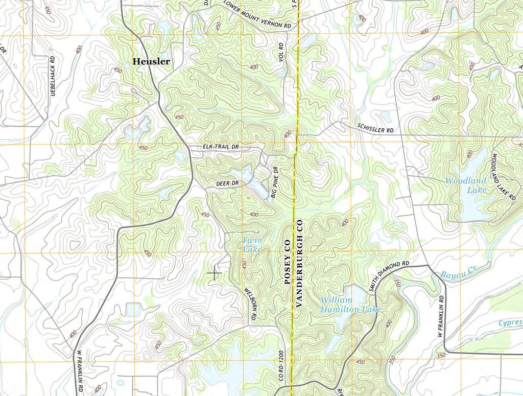
4 1-1 Introduction 1 Introduction 1.1 Purpose of this Report The purpose of the Initial Structural Stability Assessment (Structural Stability Assessment) presented in this report is to document that the requirements specified in 40 Code of Federal Regulations (CFR) (d) have been met to support the certification required under each of the applicable regulatory provisions for the A.B. Brown Generating Station (Brown) Ash Pond. The Brown Ash Pond is an existing coal combustion residual (CCR) surface impoundment as defined by 40 CFR The CCR Rule requires that the structural stability assessment for an existing CCR surface impoundment be prepared by October 17, The Brown station has an interconnected existing CCR surface impoundment, the Ash Pond, which consists of a lower pool and an upper pool. The following table summarizes the documentation required within the CCR Rule and the sections that specifically respond to those requirements of this assessment. Table 1-1 CCR Rule Cross Reference Table Report Section Title CCR Rule Reference 2.1 Foundations and Abutments (d)(1)(i) 2.2 Slope Protection (d)(1)(ii) 2.3 Dike Compaction (d)(1)(iii) 2.4 Vegetated Slopes (d)(1)(iv) 2.5 Spillways (d)(1)(v) 2.6 Stability and Structural Integrity of Hydraulic Structures (d)(1)(vi) 2.7 Downstream Slope Inundation / Stability (d)(1)(vii) 1.2 Brief Description of Impoundment The Brown station is a coal-fired power plant located approximately 10 miles east of Mount Vernon in Posey County, Indiana and is owned and operated by Southern Indiana Gas & Electric Company, dba Vectren Power Supply, Inc. (SIGECO). The Brown station is situated just west of the Vanderburgh-Posey County line and north of the Ohio River with the Ash Pond positioned on the east side of the generating station. The Ash Pond was commissioned in An earthen dam was constructed across an existing valley to create the impoundment. In 2003, a second dam was constructed east of the original dam and further up the valley to increase the storage capacity. This temporarily created an upper pond and a lower pond. The upper and lower ponds were operated separately until 2016 when the upper dam was decommissioned. A 10 wide breach was installed in the upper embankment and the normal pool elevation was lowered. Currently, the upper pool and the
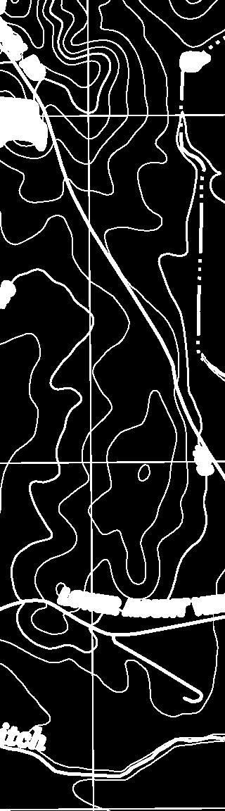
5 1-2 Introduction lower pool act as one CCR unit referred to as the Ash Pond, which has a surface area of approximately 159 acres. The lower pool dam embankment is approximately 1,540 feet long, 30 feet high, and has 3 to 1 (horizontal to vertical) side slopes covered with grassy vegetation. The embankment crest elevation is feet 1 and has a crest width of 20 feet. An earthen buttress was constructed against the outboard slope of the dam. The buttress crest extends the length of the dam, is up to 200 feet wide and varies in elevation from 442 feet to 432 feet. A site Location Map showing the area surrounding the station is included as Figure 1 of Appendix A. Figure 2 in Appendix A presents the Brown Site Map. 1 Unless otherwise noted, all elevations in this report are in the NAVD88 datum.
6 2-1 Structural Stability Assessment Description 2 Structural Stability Assessment Description Regulatory Citation: 40 CFR (d)(1); The owner or operator of the CCR unit must conduct initial and periodic structural stability assessments and document whether the design, construction, operation, and maintenance of the CCR unit is consistent with recognized and generally accepted good engineering practices for the maximum volume of CCR and CCR wastewater which can be impounded therein. The assessment must, at a minimum, document whether the CCR unit has been designed, constructed, operated, and maintained with [the standards in (d)(1)(i)-(vii)]: The Structural Stability Analysis for the Ash Pond is described in this section. Information about operational and maintenance procedures was provided by Brown plant personnel. The Brown station follows an established maintenance program that quickly identifies and resolves issues of concern. 2.1 Foundations and Abutments Regulatory Citation: 40 CFR (d)(1); (i) Stable foundations and abutments; Background and Assessment The stability of the foundations was evaluated using soil data from field investigations and reviewing design drawings, operational and maintenance procedures, and conditions observed in the field by AECOM. Additionally, slope stability analyses were performed to evaluate slip surfaces passing through the foundations. The foundation soils consist of interbedded stiff to very stiff clay and loose to medium dense silt soils. While the silts are susceptible to liquefaction as a result of strong earthquake shaking, the slope stability analyses exceed the criteria listed in (e)(1) for slip surfaces passing through the foundation (including the post-liquefaction loading condition). Therefore, the foundation soils are considered to be stable under all loading conditions. The slope stability analyses are discussed in the CCR Certification Report: Initial Safety Factor Assessment for the Ash Pond at the A.B. Brown Generating Station (October 2016). A review of operational and maintenance procedures as well as current and past performance of the dikes has determined appropriate processes are in place for continued operational performance. Conclusion and Recommendation Based on the conditions observed by AECOM, the Ash Pond was designed and constructed with stable foundations. Operational and maintenance procedures are in place to address any issues related to the stability of foundations. Therefore, the Ash Pond meets the requirements in (d)(1)(i).
7 2-2 Structural Stability Assessment Description 2.2 Slope Protection Regulatory Citation: 40 CFR (d)(1); (ii) Adequate slope protection to protect against surface erosion, wave action and adverse effects of sudden drawdown; Background and Assessment The adequacy of slope protection was evaluated by reviewing design drawings, operational and maintenance procedures, and conditions observed in the field by AECOM. The exterior slopes of the lower pool berm are covered with grass vegetation. The interior slopes of the lower pool and upper pool berms are covered with rip-rap which has an approximate median diameter of 15-inches. No evidence of significant areas of erosion or wave action was observed during AECOM s site visit on February 23, See Appendix B for further details from AECOM s site visit. Due to the recent installation of a buttress at the toe of the lower pool embankment, vegetation has not been fully established on the buttress. After construction of the buttress was completed in October 2016, seed was placed on the disturbed areas, and a straw mat was installed to protect the area from erosion during the growing season. Grass has begun to grow, but will require additional time to become adequately established. Conclusion and Recommendation Based on this evaluation, adequate slope protection was designed and constructed at the Ash Pond. Areas outside of the limits of construction of the buttress show no evidence of significant areas of erosion or wave action. However, areas within the limits of the buttress construction that are not fully vegetated due to recent construction are protected against wind and stormwater erosion with straw mat and must be inspected regularly and repaired as necessary until they are adequately vegetated. Operational and maintenance procedures to repair the vegetation (exterior slopes) and rip-rap (interior slopes) as needed are appropriate to protect against surface erosion or wave action. Sudden drawdown of the pool in the Ash Pond is not expected to occur. See Section 2.7 of this report for further information on sudden drawdown. Therefore, the Ash Pond meets the requirements in (d)(1)(ii). 2.3 Dike Compaction Regulatory Citation: 40 CFR (d)(1) (iii) Dikes mechanically compacted to a density sufficient to withstand the range of loading conditions in the CCR unit; Background and Assessment The density of the dike materials was evaluated using soil data from field investigations and reviewing design drawings, operational and maintenance procedures, and conditions observed in the field by AECOM. Additionally, slope stability analyses were performed to evaluate slip surfaces passing through the dike over the range of expected loading conditions as defined within (e)(1).
8 2-3 Structural Stability Assessment Description Historical construction drawings for the dam required that the embankment be compacted to 95% of the Standard Proctor maximum dry density (ASTM D 698). Based on the geotechnical field evaluations, the dam embankment consists of stiff to very stiff clayey soils that have consistency and strength indicative of well-compacted materials. The soil buttress that exists against the downstream slope of the dam was constructed in 8-inch loose lifts and was mechanically compacted to at least 95% of the Standard Proctor maximum dry density. Soil densities for the buttress were verified using nuclear methods. Slope stability analyses exceed the criteria listed in (e)(1) for slip surfaces passing through the dike. The slope stability analyses and results are discussed in the CCR Rule Report: Initial Safety Factor Assessment (October 2016). Conclusion and Recommendation Based on the conditions observed by AECOM, the Ash Pond was designed and constructed with sufficient dike compaction. Therefore, the Ash Pond meets the requirements in (d)(1)(iii). 2.4 Vegetated Slopes Regulatory Citation: 40 CFR (d)(1) (iv) Vegetated slopes of dikes and surrounding areas, except for slopes which have an alternate form or forms of slope protection; 2 Background and Assessment The adequacy of slope vegetation was evaluated by reviewing design drawings, operational and maintenance procedures, and conditions observed in the field by AECOM. The exterior slopes of the lower pool berm are covered with grass vegetation. No evidence of significant areas of erosion was observed during AECOM s site visit on February 23, See Appendix B for further details from AECOM s site visit. Due to the recent installation of a buttress at the toe of the lower pool embankment, vegetation was not fully established in the construction area. After construction of the buttress was completed in October 2016, seed was placed on the disturbed areas, and a straw mat was installed to protect the seed from erosion during the growing season. Grass has begun to grow, but will require additional time to become adequately established. Conclusion and Recommendation Based on this evaluation, the vegetation on the exterior slopes of the areas outside of the limits of construction of the buttress is adequate as no substantial bare or overgrown areas were observed. Therefore, the original design and construction of the Ash Pond included adequate vegetation of the dikes and surrounding areas. Areas within the limits of the buttress construction that are not fully vegetated due to recent construction are protected against wind and stormwater erosion with straw mat and must be inspected regularly and repaired as necessary until they are adequately vegetated. Adequate operational and maintenance procedures are in place to regularly manage 2 As modified by court order issued June 14, 2016, Utility Solid Waste Activities Group v. EPA, D.C. Cir. No (order granting remand and vacatur of specific regulatory provisions).
9 2-4 Structural Stability Assessment Description vegetation growth, including mowing and seeding any bare areas, and to address erosional issues as they occur, as evidenced by the conditions observed by AECOM. Therefore, the Ash Pond meets the requirements in (d)(1)(iv). 2.5 Spillways Regulatory Citation: 40 CFR (d)(1) (v) single spillway or a combination of spillways configured as specified in [paragraph (A) and (B)]: (A) All spillways must be either: (1) of non-erodible construction and designed to carry sustained flows; or (2) earth- or grass-lined and designed to carry short-term, infrequent flows at non-erosive velocities where sustained flows are not expected. (B) The combined capacity of all spillways must adequately manage flow during and following the peak discharge from a: Background and Assessment (1) Probable maximum flood (PMF) for a high hazard potential CCR surface impoundment; or (2) 1000-year flood for a significant hazard potential CCR surface impoundment; or (3) 100-year flood for a low hazard potential CCR surface impoundment. The plant operates as a zero-discharge facility during normal operating conditions, so it is uncommon for water to discharge from the lower pool. However, if a discharge does occur, the runoff drains through the permitted NPDES outfall to an unnamed tributary which travels west for approximately 0.5 mile before turning south for approximately one mile and discharging into the Ohio River. There are five spillways available for discharge runoff from the lower pool. These spillways were evaluated using design drawings, operational and maintenance procedures, and conditions observed in the field by AECOM. The conditions of each structure were observed in the field by AECOM February 23, See Site Visit Report in Appendix B for additional details. The first outlet is a 12-inch HDPE Ash Pond Discharge Line that goes to a chemical precipitation treatment system prior to mixing with other plant water and going to an NPDES permitted outfall. The HDPE pipe is a nonerodible material. The second outlet is a Low Pressure Recirculation System. This system is comprised of three pumps that are rated for 2,750 gpm each. All three pumps discharge into individual 8-inch diameter carbon steel pipes before combining into a common header and proceeding as a 20-inch diameter carbon steel pipeline to the plant. The carbon steel pipe is a non-erodible material. The third outlet is a High Pressure Recirculation System. This system is comprised of two high pressure pumps that are rated for 2,100 gpm each. Both pumps discharge into individual 8-inch diameter carbon steel pipes before combining into a common header and proceeding as a 10-inch diameter carbon steel pipeline to the plant. The carbons steel pipe is a non-erodible material.
10 2-5 Structural Stability Assessment Description The fourth outlet is the Principal Spillway which consists of a metal gooseneck inlet structure connected to a 36- inch RCP drop inlet. Discharge from the inlet flows to a 36-inch diameter RCP pipe that discharges near the toe of the embankment. The steel and RCP pipes of the Principal Spillway are non-erodible material. The fifth outlet is the Emergency Spillway which is a grass-lined, trapezoidal channel spillway. Class II rip-rap, which has a median diameter of approximately 15-inches, was used to line the discharge channel to prevent erosion. The grass-lined spillway and the rip-rap lined channel of the Emergency Spillway discharge channel were designed to prevent erosion. The velocities through the spillways during peak discharge were analyzed to determine if erosion would occur within preparation of the CCR Certification: Initial Inflow Design Flood Control System Plan (October 2016). Additionally, hydrologic and hydraulic analyses were completed to evaluate the capacity of the spillway relative to inflow estimated for the 1,000-year flood event for the significant hazard potential for the Ash Pond. The ability of the spillway design to carry sustained flows, as well as the capacity of the spillway, was evaluated using hydrologic and hydraulic analysis performed per (a). The hydrologic and hydraulic analyses are discussed in the CCR Certification: Initial Inflow Design Flood Control System Plan for the Ash Pond at the A.B. Brown Generating Station (October 2016). Conclusion and Recommendation All outlet devices were designed to prevent erosion. The HDPE, steel and RCP pipes of the outlets are nonerodible material, while the channel of the Emergency Spillway is lined with rip-rap. The analysis found that the spillways can adequately manage flow during peak discharge resulting from the 1,000-year storm event without overtopping of the embankments. The peak water surcharge elevation is feet during the IDF, and the minimum crest elevation of the Ash Pond dike is feet, resulting in 4.1 feet of freeboard. This also indicates that the design of the spillway is adequate to carry sustained flows. Operational and maintenance procedures are in place to remove debris or other obstructions from the spillway, if observed after normal inspections. As a result, these procedures are appropriate for maintaining the spillway. Therefore, the Ash Pond meets the requirements in (d)(1)(v). 2.6 Stability and Structural Integrity of Hydraulic Structures Regulatory Citation: 40 CFR (d)(1) (vi) Hydraulic structures underlying the base of the CCR unit or passing through the dike of the CCR unit that maintain structural integrity and are free of significant deterioration, deformation, distortion, bedding deficiencies, sedimentation, and debris which may negatively affect the operation of the hydraulic structure. Background and Assessment The stability and structural integrity of hydraulic structures penetrating the dike of the Ash Pond was evaluated using design drawings, operational and maintenance procedures, inspections, and conditions observed in the field by AECOM. The only hydraulic structure that penetrates the lower pool embankment is the Principal Spillway. This gooseneck inlet structure is attached to a vertical 36-inch RCP drop inlet which connects to a horizontal 36-inch diameter
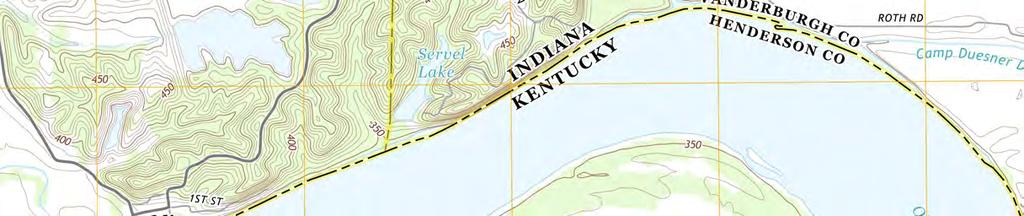
11 2-6 Structural Stability Assessment Description RCP pipe that outlets near the toe of the embankment. A visual inspection of this spillway structure was completed by AECOM on February 23, See AECOM s Site Visit Report in Appendix B for additional information. SIGECO contracted Stantec Consulting Service, Inc. (Stantec) to inspect the gooseneck structure. This inspection was completed December 4 th and 5 th, 2014 by Hydromax USA via closed-circuit television (CCTV) for the vertical and horizontal portions of this structure. Stantec reviewed this video and noted 4, grade 5 areas, all notated as Surface Reinforcement Visible. Stantec concluded there was no indication of active staining of the interior of the pipe, which would have indicated possible intrusion of the surrounding soil into the pipe at these locations or at any pipe joints. The signed report by Stantec concludes that the noted defects are not expected to adversely impact the structural integrity of the discharge pipes, but that they should be CCTV inspected periodically and the inspection video compared to the original video. Stantec also noted a 15-inch diversion conduit SIGECO identified as plugged with concrete. The historical drawings indicate that the pipe is 24-inch, reinforced concrete with anti-seep collars, plugged at the upstream end. Stantec was unable to verify the plug location and length of plugged segment. Other inspection methods were considered for the vertical stand of the Principal Spillway but were discarded due to the physical impracticality of the methods and potential employee or contractor safety concerns. Conclusion and Recommendation Based on this evaluation, the Principal Spillway structure did not display any areas of significant deterioration, deformation, distortion, bedding deficiencies, sedimentation, or debris that may negatively affect the operation of the structure. Operational and maintenance procedures are in place to remove debris or other obstructions from the hydraulic structures, and address any deficiencies, as evidenced by conditions observed by AECOM. As a result, these procedures are appropriate for maintaining in the stability and structural integrity of the hydraulic structure. There is no current evidence of ash transport within the pipe and no noted signs of failure. However, since the pipe is a potential pathway for ash release from the impoundment, AECOM recommends a CCTV inspection of the Principal Spillway every other year, including the previous diversion conduit, as far as practical. Comparison of a current, bi-annual video to the baseline video established in 2014 provides for identification of potential changes in the pipe, joints, or staining which could be indicative of deterioration, deformation or distortion. Therefore, the Ash Pond meets the requirements in (d)(1)(vi). 2.7 Downstream Slope Inundation / Stability Regulatory Citation: 40 CFR (d)(1) (vii) For CCR units with downstream slopes which can be inundated by the pool of an adjacent water body, such as a river, stream or lake, downstream slopes that maintain structural stability during low pool of the adjacent water body or sudden drawdown of the adjacent water body. Background and Assessment The structural stability of the downstream slopes of the Ash Pond was evaluated by comparing the location of the Ash Pond relative to adjacent water bodies using published United States Geological Survey (USGS) topographic maps, aerial imagery, and conditions observed in the field by AECOM.
12 2-7 Structural Stability Assessment Description Based on this evaluation, water bodies adjacent to the downstream slopes of the Ash Pond are not present. The nearest downstream water body is the Ohio River, which is approximately 2,500 lateral feet beyond the downstream slopes of the Ash Pond. The 100 year flood event (elevation 373 feet) from the Ohio River is 77 feet below the elevation of the toe of the lower pool berm. Therefore, there are no adjacent water bodies that can inundate the downstream slopes of the Ash Pond. Conclusion and Recommendation Based on this evaluation, the requirements in (d)(1)(vii) are not applicable to the Ash Pond, as inundation of the downstream slopes is not expected to occur.


13
14 4-1 Limitations 4 Limitations Background information, design basis, and other data which AECOM has used in preparation of this report have been furnished to AECOM by SIGECO. AECOM has relied on this information as furnished, and is not responsible for the accuracy of this information. Our recommendations are based on available information from previous and current investigations. These recommendations may be updated as future investigations are performed. The conclusions presented in this report are intended only for the purpose, site location, and project indicated. The recommendations presented in this report should not be used for other projects or purposes. Conclusions or recommendations made from these data by others are their responsibility. The conclusions and recommendations are based on AECOM s understanding of current plant operations, maintenance, stormwater handling, and ash handling procedures at the station, as provided by SIGECO. Changes in any of these operations or procedures may invalidate the findings in this report until AECOM has had the opportunity to review the findings, and revise the report if necessary. This development of the Initial Structural Stability Assessment was performed in accordance with the standard of care commonly used as state-of-practice in our profession. Specifically, our services have been performed in accordance with accepted principles and practices of the engineering profession. The conclusions presented in this report are professional opinions based on the indicated project criteria and data available at the time this report was prepared. Our services were provided in a manner consistent with the level of care and skill ordinarily exercised by other professional consultants under similar circumstances. No other representation is intended.
15 Appendix A Figures Figure 1 Location Map Figure 2 Site Map


16 9400 Amberglen Boulevard Austin, TX (phone) (fax) SOUTHERN INDIANA GAS AND ELECTRIC COMPANY dba VECTREN POWER SUPPLY, INC. One Vectren Square Evansville, IN (phone) A.B. BROWN GENERATING STATION MT. VERNON, IN CCR CERTIFICATION ASH POND ISSUED FOR CERTIFICATION UPPER ASH POOL ISSUED FOR BIDDING DATE BY ISSUED FOR CONSTRUCTION DATE BY A.B. BROWN GENERATING STATION REVISIONS NO. DESCRIPTION DATE LOWER ASH POOL AECOM PROJECT NO: DRAWN BY: DESIGNED BY: CHECKED BY: DATE CREATED: PLOT DATE: SCALE: ACAD VER: MJC MJC TLE 4/22/2016 AS SHOWN 2014 SHEET TITLE LOCATION MAP SCALE IN FEET
 A.B. BROWN GENERATING STATION MT.")
17 9400 Amberglen Boulevard Austin, TX (phone) (fax) SOUTHERN INDIANA GAS AND ELECTRIC COMPANY dba VECTREN POWER SUPPLY, INC. One Vectren Square Evansville, IN (phone) A.B. BROWN GENERATING STATION MT. VERNON, IN CCR CERTIFICATION ASH POND GENERATING STATION UPPER ASH POOL ISSUED FOR CERTIFICATION ISSUED FOR BIDDING DATE BY LOWER ASH POOL PRIMARY OUTLET DEVICE 63" HDPE DROP INLET ISSUED FOR CONSTRUCTION REVISIONS DATE BY PUMP STATION SECONDARY OUTLET DEVICE 10' WIDE TRAPEZOIDAL BREACH NO. DESCRIPTION DATE PRIMARY OUTLET DEVICE 36" HDPE DROP INLET TRIBUTARY TO THE OHIO RIVER SECONDARY OUTLET DEVICE 30' WIDE TRAPEZOIDAL EMERGENCY SPILLWAY AECOM PROJECT NO: DRAWN BY: DESIGNED BY: CHECKED BY: DATE CREATED: PLOT DATE: SCALE: ACAD VER: SHEET TITLE MJC MJC TLE 4/22/2016 AS SHOWN SITE MAP SCALE IN FEET OHIO RIVER
18 Appendix B AECOM Site Visit Report
19 STATION SITE VISIT SUMMARY Station: Station Location: A.B. Brown Generating Station Indiana Site Visit Date: 02/23/2016 Prepared by: Checked by: ITR by: Distribution to: Background: Teresa L. Entwistle, PE (AECOM) John Davis, PE (AECOM) Vik Gautam, PE (AECOM) File AECOM engineering and program management team visited the A.B. Brown Generating Station (Brown) and were accompanied by Vectren personnel. AECOM personnel inspected the Ash Pond at the Brown station to assess the unit in regards to the CCR Rule and to better understand the operating methods of the surface impoundment for the analysis required under the CCR Rule. Engineering design personnel that toured the facility included Teresa Entwistle, John Davis, Vik Gautam, and John Priebe. AECOM program management personnel included Tommy Bell, Milton Owen, Ty Cloud and Steven Kosler. Vectren personnel present included Lisa Messinger, Chris Leslie, and John Minnette. Summary of Observation/Comments on Site Visit: AECOM performed a visual inspection of the Ash Pond and the areas surrounding the Ash Pond. Inspections were conducted from the top of the downstream berm of the unit along an access road and from the west side of the impoundment via an access road between the unit and the generating station. The surface impoundment was created by the construction of an earthen dam across an existing valley. A secondary berm is located upstream of the lower berm to separate the Ash Pond into two operating pools, the upper pool and the lower pool. Drainage into the surface impoundment is from pumped process flows, rainfall falling directly onto the surface impoundment and from runoff from upstream areas. Discharge from the unit is via an active pumping station that recycles the water back to the generating station for process use. The plant operates as a zero-discharge facility during normal conditions, so it is uncommon for water to discharge from the unit. However, if a discharge does occur, the runoff drains through the permitted NPDES outfall to an unnamed tributary which travels west for approximately 0.5 mile before turning south for approximately one mile and discharging into the Ohio River. Two emergency overflow structures are present, a primary spillway consisting of a gooseneck that penetrates the lower berm and a grass lined trapezoidal secondary emergency spillway channel. The gooseneck ties into a vertical riser that ties into a 36-inch Class V, reinforced concrete pipe (RCP). A junction chamber enables the transition from the vertical section of the RCP to the horizontal section of the RCP. No seepage was observed on the exterior of the berm at the locations of these penetrations or along the downstream slope of the berm. Vectren personnel informed AECOM that a video-taped inspection of the interior of the gooseneck was performed by others and will be submitted to AECOM for review. The secondary emergency spillway is protected by established grass cover. The discharge from this spillway is a riprap lined channel. Slope protection included established grass cover along the external slopes of the impoundment berm and riprap along the interior slopes. No downstream structures were observed between the unit and the Ohio River. This communication contains privileged and confidential information, and is intended solely for the persons or organizations to whom it is addressed. If you are not the intended recipient, you should not copy, distribute or take any action in reliance on it. Page 1 of 5


20 STATION SITE VISIT SUMMARY Photo No. 1 Date: 02/23/2016 Location: A.B. Brown Generating Station Description: Standing at east end of berm, looking west. Picture shows slope protection on downslope of berm. Photographer: Entwistle Photo No. 2 Date: 11/04/2015 Location: A.B. Brown Generating Station Description: Standing at west end of berm, looking east. Picture shows slope protection on downslope of berm. Photographer: Entwistle This communication contains privileged and confidential information, and is intended solely for the persons or organizations to whom it is addressed. If you are not the intended recipient, you should not copy, distribute or take any action in reliance on it. Page 2 of 5


21 STATION SITE VISIT SUMMARY Photo No. 3 Date: 02/23/2016 Location: A.B. Brown Generating Station Description: Standing on western leg of berm, looking north. Picture shows slope protection on exterior face of berm. Photographer: Entwistle Photo No. 4 Date: 11/04/2015 Location: A.B. Brown Generating Station Description: Standing midway along southern berm, looking back over surface impoundment. Picture shows stability of berm into surface impoundment. Photographer: Entwistle This communication contains privileged and confidential information, and is intended solely for the persons or organizations to whom it is addressed. If you are not the intended recipient, you should not copy, distribute or take any action in reliance on it. Page 3 of 5


22 STATION SITE VISIT SUMMARY Photo No. 5 Date: 02/23/2016 Location: A.B. Brown Generating Station Description: Standing in secondary emergency spillway looking downstream. Picture shows adequate slope protection and no evidence of erosion. Photographer: Entwistle Photo No. 6 Date: 02/23/2016 Location: A.B. Brown Generating Station Description: Standing at top of secondary emergency spillway, showing riprap lining of discharge channel Picture shows adequate erosion protection. Photographer: Entwistle This communication contains privileged and confidential information, and is intended solely for the persons or organizations to whom it is addressed. If you are not the intended recipient, you should not copy, distribute or take any action in reliance on it. Page 4 of 5

23 STATION SITE VISIT SUMMARY Photo No. 7 Date: 02/23/2016 Location: A.B. Brown Generating Station Description: Standing on the pumping station. Picture shows inlet to gooseneck emergency overflow penetration into lower berm. Video of this structure provided separately. Photographer: Entwistle This communication contains privileged and confidential information, and is intended solely for the persons or organizations to whom it is addressed. If you are not the intended recipient, you should not copy, distribute or take any action in reliance on it. Page 5 of 5
24 Attorney-Client Privileged 9400 Amberglen Boulevard Austin, Texas About AECOM AECOM (NYSE: ACM) is a global provider of professional technical and management support services to a broad range of markets, including transportation, facilities, environmental, energy, water and government. With approximately 45,000 employees around the world, AECOM is a leader in all of the key markets that it serves. AECOM provides a blend of global reach, local knowledge, innovation, and collaborative technical excellence in delivering solutions that enhance and sustain the world s built, natural, and social environments. A Fortune 500 company, AECOM serves clients in more than 100 countries and has annual revenue in excess of $6 billion..
Watershed size and name: The drainage area is acres. The pond is located within the Ohio River watershed. (2016 Inflow Design Plan)
") A. B. Brown History of Construction 40 CFR 257.73 (c) (i.) (ii.) (iii.) Owner Name: Southern Indiana Gas and Electric Company dba Vectren Power Supply Owner Address: One Vectren Square, PO Box 209, Evansville,
A. B. Brown History of Construction 40 CFR 257.73 (c) (i.) (ii.) (iii.) Owner Name: Southern Indiana Gas and Electric Company dba Vectren Power Supply Owner Address: One Vectren Square, PO Box 209, Evansville,
CCR Annual Inspection (b) for the Ash Pond at the San Miguel Plant. Revision 0
 for the Ash Pond at the San Miguel Plant. Revision 0") Submitted to San Miguel Electric Cooperative, Inc. 6200 FM 3387 Christine, Texas 78012 Submitted by AECOM 9400 Amberglen Boulevard Austin, Texas 78729 257.83 (b) for the Ash Pond at the San Miguel Plant
Submitted to San Miguel Electric Cooperative, Inc. 6200 FM 3387 Christine, Texas 78012 Submitted by AECOM 9400 Amberglen Boulevard Austin, Texas 78729 257.83 (b) for the Ash Pond at the San Miguel Plant
Mr. Michael Malone CPS Energy 145 Navarro Street San Antonio, Texas Project No
 Environmental Resources Management January 13, 2017 Mr. Michael Malone 145 Navarro Street San Antonio, Texas 78205 Project No. 0352436 CityCentre Four 840 West Sam Houston Parkway North, Suite 600 Houston,
INFLOW DESIGN FLOOD CONTROL SYSTEM PLAN PLANT BARRY ASH POND ALABAMA POWER COMPANY
 INFLOW DESIGN FLOOD CONTROL SYSTEM PLAN PLANT BARRY ASH POND ALABAMA POWER COMPANY Section 257.82 of EPA s regulations requires the owner or operator of an existing or new CCR surface impoundment or any
Lyon Creek Cedar Way Stormwater Detention Dam Operation and Maintenance Manual
 Lyon Creek Cedar Way Stormwater Detention Dam Operation and Maintenance Manual Prepared by: Mike Shaw Stormwater Program Manager City of Mountlake Terrace January 2010 Section I General Information This
Ottumwa Generating Station Project No Closure Plan for Existing CCR Revision: 0 Surface Impoundments TABLE OF CONTENTS
 Surface Impoundments Page No. i TABLE OF CONTENTS 1. INTRODUCTION... 1 2. PROPOSED CCR IMPOUNDMENTS CLOSURE PROCEDURE... 3 3. PROPOSED COVER SYSTEM... 4 4. ESTIMATED MAXIMUM INVENTORY OF CCR... 4 5. ESTIMATED
Table of Contents. Attachments Attachment A Photos Attachment B Inspection Map. Pages 3 of 10
 Table of Contents 1.0 Introduction...4 2.0 Description of Landfill...4 3.0 Review of Available Information...5 4.0 Inspection...5 4.1 Changes in Geometry since Last Inspection...5 4.2 Volume...5 4.3 Definitions
SECTION 3 DRAINAGE. 3-1 General. 3-2 Drainage Ordinances and Legal Requirements
 SECTION 3 DRAINAGE 3-1 General All Drainage plans for proposed development shall be prepared by a Professional Engineer registered in Virginia, except as noted below. Further, their seal and signature
CLOSURE PLAN. CFR (b) Document No. GERS Stingy Run Flyash Pond. Gavin Plant Cheshire, Ohio. October, 2016
 Document No. GERS Stingy Run Flyash Pond. Gavin Plant Cheshire, Ohio. October, 2016") CLOSURE PLAN CFR 257.102(b) Stingy Run Flyash Pond Gavin Plant Cheshire, Ohio October, 2016 Prepared for: AEP Generation Resources Gavin Plant Cheshire, Ohio Prepared by: American Electric Power Service
CLOSURE PLAN CFR 257.102(b) Stingy Run Flyash Pond Gavin Plant Cheshire, Ohio October, 2016 Prepared for: AEP Generation Resources Gavin Plant Cheshire, Ohio Prepared by: American Electric Power Service
Stormwater Local Design Manual For Houston County, Georgia
 Stormwater Local Design Manual For Houston County, Georgia Adopted November 15, 2005 TABLE OF CONTENTS 1. FORWARD... 1 2. GENERAL LEVEL OF SERVICE STANDARDS... 2 2.1. DETENTION REQUIREMENTS... 2 2.1.1.
TVA Colbert Fossil Facility Ash Disposal Pond 4
 2011 World of Coal Ash (WOCA) Conference May 9-12, 2011 in Denver, CO, USA http://www.flyash.info/ TVA Colbert Fossil Facility Ash Disposal Pond 4 Improving Operations While Preparing for Closure May 10,
Ponds. Pond A water impoundment made by excavating a pit, or constructing a dam or an embankment.
 POND SITE SELECTION AND CONSTRUCTION Uses, Planning, & Design David Krietemeyer Area Engineer USDA-NRCS June 20, 2008 Uses Considerations for Location of Commonly Used Terms Pond A water impoundment made
MODEL Stormwater Local Design Manual. City of Centerville
 MODEL Stormwater Local Design Manual City of Centerville Adopted December 6, 2005 TABLE OF CONTENTS 1. FORWARD... 1 2. GENERAL LEVEL OF SERVICE STANDARDS... 1 2.1. DETENTION REQUIREMENTS... 1 2.1.1. Discharge
Stantec Consulting Services Inc Lebanon Road, Cincinnati, OH 45241
 Stantec Consulting Services Inc. 11687 Lebanon Road, Cincinnati, OH 45241 File: 175534017 Revision 0 Ohio Valley Electric Corporation 3932 U.S. Route 23 P.O. Box 468 Piketon, Ohio 45661 RE: Run-on and
ENVIRONMENTAL ENGINEERING LAND SURVEYING
 ENVIRONMENTAL ENGINEERING LAND SURVEYING Inflow Design Flood Control System Plan Bottom Ash Pond Sherburne County Generating Plant Introduction This report presents documentation and certification of the
SECTION STORM DRAINAGE DESIGN, GRADING, AND WATER QUALITY TECHNICAL CRITERIA TABLE OF CONTENTS PAGE 402 STORM DRAINAGE DESIGN CRITERIA 400-1
 CITY OF THORNTON Standards and Specifications Revised: October 2012 SECTION 400 - STORM DRAINAGE DESIGN, GRADING, AND WATER QUALITY TECHNICAL CRITERIA TABLE OF CONTENTS PAGE 401 GENERAL PROVISIONS 400-1
Sediment Basin. Fe= (Depends on soil type)
") 3.9 Sediment Control Description: A sediment basin is an embankment with a controlled outlet that detains stormwater runoff, resulting in the settling of suspended sediment. The basin provides treatment
3.9 Sediment Control Description: A sediment basin is an embankment with a controlled outlet that detains stormwater runoff, resulting in the settling of suspended sediment. The basin provides treatment
Final Summary Report Structural Integrity Assessment Bottom Ash Pond Cholla Power Plant Joseph City, Arizona
 Submitted to Arizona Public Service Generation Engineering P.O. Box 53999 Phoenix, AZ 85072 Submitted by AECOM 7720 North 16 th Street Suite 100 Phoenix, AZ 85020 August 26, 2016 Final Summary Report Structural
The Relationship Between Water and the CCR Rule
 The Relationship Between Water and the CCR Rule A Vital Issue for CCR Rule Compliance Teresa L. Entwistle, P.E., CFM AECOM St. Louis, MO 07.11.16 MWCC Conference Introduction With the strict regulations
Lansing Generating Station Project No Closure Plan for Existing CCR Revision: 1 TABLE OF CONTENTS
 Surface Impoundment Page No. i TABLE OF CONTENTS 1. INTRODUCTION... 1 2. PROPOSED CCR IMPOUNDMENT CLOSURE PROCEDURE... 2 3. PROPOSED COVER SYSTEM... 2 4. ESTIMATED MAXIMUM INVENTORY OF CCR... 3 5. ESTIMATED
HAZARD POTENTIAL CLASSIFICATION REPORT
 HAZARD POTENTIAL CLASSIFICATION REPORT PONDS 1 & 2, JR WHITING PLANT ERIE, MICHIGAN OCTOBER 13, 2016 PREPARED FOR: CONSUMERS ENERGY COMPANY TABLE OF CONTENTS SECTION: PAGE NO.: Certification... i 1.0 Introduction...
Coal Combustion Facility Assessment Report. October 20, 2010
 Coal Combustion Facility Assessment Report October 20, 2010 Introduction Stantec Consulting Services Inc. North American Consulting Firm 10,000 Engineers, Geologists, Architects, Scientists and Technicians
2016 LANDFILL INSPECTION REPORT CARDINAL PLANT BRILLIANT, OHIO
 2016 LANDFILL INSPECTION REPORT GERS-16-004 CARDINAL PLANT BRILLIANT, OHIO PREPARED BY GEOTECHNICAL ENGINEERING AEP SERVICE CORPORATION 1 RIVERSIDE PLAZA COLUMBUS, OHIO Cardinal Plant Landfill Inspection
Standards for Soil Erosion and Sediment Control in New Jersey May 2012 STANDARD FOR SLOPE PROTECTION STRUCTURES. Definition
 STANDARD FOR SLOPE PROTECTION STRUCTURES Definition Structures to safely conduct surface runoff from the top of a slope to the bottom of the slope. Purpose The purpose of this practice is to convey storm
ARTICLE V: STORMWATER MANAGEMENT AND DRAINAGE SYSTEMS
 ARTICLE V: STORMWATER MANAGEMENT AND DRAINAGE SYSTEMS Section 501: Purpose An adequate drainage system including necessary ditches, pipes, culverts, drains, inlets, bridges, detention ponds, etc. shall
1. Regulation Requirements
 16644 est Bernardo Drive, Suite 301 San Diego, CA 92127 Phone: 858.674.6559 Fax: 858.674.6586 www.geosyntec.com STRUCTURAL STABILITY AND FACTOR OF SAFETY ASSESSMENT ASH POND 2 JOLIET 29 STATION OCTOBER
LANDFILL CLOSURE PLAN ENTERGY ARKANSAS, INC. INDEPENDENCE PLANT CLASS 3N CCR LANDFILL PERMIT NO S3N-R2 AFIN
 LANDFILL CLOSURE PLAN ENTERGY ARKANSAS, INC. INDEPENDENCE PLANT CLASS 3N CCR LANDFILL PERMIT NO. 0200-S3N-R2 AFIN 32-00042 OCTOBER 12, 2016 LANDFILL CLOSURE PLAN ENTERGY ARKANSAS, INC. INDEPENDENCE PLANT
Types of Inspections. Prior to Inspection. Types of Inspections. Typical Inspection Equipment. Embankment Dams
 BIA Summer Water Resources Training Dam Safety Inspections Part 4 - Inspections July 28, 2012 Presented by Michael Johnson, Ph.D., P.E. Types of Inspections Periodic Inspections A comprehensive visual
NEW CASTLE CONSERVATION DISTRICT. through. (Name of Municipality) PLAN REVIEW APPLICATION DRAINAGE, STORMWATER MANAGEMENT, EROSION & SEDIMENT CONTROL
 PLAN REVIEW APPLICATION DRAINAGE, STORMWATER MANAGEMENT, EROSION & SEDIMENT CONTROL") NEW CASTLE CONSERVATION DISTRICT through (Name of Municipality) PLAN REVIEW APPLICATION DRAINAGE, STORMWATER MANAGEMENT, EROSION & SEDIMENT CONTROL Office use only: Received by Municipality: Received by
NEW CASTLE CONSERVATION DISTRICT through (Name of Municipality) PLAN REVIEW APPLICATION DRAINAGE, STORMWATER MANAGEMENT, EROSION & SEDIMENT CONTROL Office use only: Received by Municipality: Received by
Highway Drainage 1- Storm Frequency and Runoff 1.1- Runoff Determination
 Highway Drainage Proper drainage is a very important consideration in design of a highway. Inadequate drainage facilities can lead to premature deterioration of the highway and the development of adverse
TEMPORARY SEDIMENT TRAP CODE
 ILLINOIS URBAN MANUAL PRACTICE STANDARD TEMPORARY SEDIMENT TRAP CODE 960 Source: DEFINITION A small temporary stormwater storage structure designed to trap sediment. PURPOSE The purpose of this practice
APPENDIX A EARTHEN EMBANKMENT. VERSION 1.0 March 1, 2011
 APPENDIX A EARTHEN EMBANKMENT VERSION 1.0 March 1, 2011 SECTION A-1: DESCRIPTION OF PRACTICE An earthen embankment is a raised impounding structure made from compacted soil. The embankment is the feature
Applying landforming to reclamation: A case study in Central Appalachia
 Applying landforming to reclamation: A case study in Central Appalachia Leslie Hopkinson, John Quaranta April 12, 2017 Department of Civil and Environmental Engineering West Virginia University WEST VIRGINIA
2015 ANNUAL ENGINEERING INSPECTION REPORT ENTERGY INDEPENDENCE PLANT CLASS 3N LANDFILL PERMIT NO S3N-R2 AFIN:
 2015 ANNUAL ENGINEERING INSPECTION REPORT ENTERGY INDEPENDENCE PLANT CLASS 3N LANDFILL PERMIT NO. 0200-S3N-R2 AFIN: 32-00042 JANUARY 15, 2016 ENTERGY INDEPENDENCE PLANT CLASS 3N LANDFILL 2015 ANNUAL ENGINEERING
CLOSURE AND POST-CLOSURE CARE PLAN JAMES RIVER POWER STATION UTILITY WASTE LANDFILL CITY UTILITIES OF SPRINGFIELD, MISSOURI
 CLOSURE AND POST-CLOSURE CARE PLAN JAMES RIVER POWER STATION UTILITY WASTE LANDFILL CITY UTILITIES OF SPRINGFIELD, MISSOURI INITIAL PREPARATION DATE: October 11, 2016 TABLE OF CONTENTS 1. CERTIFICATION
PAPERWORK REDUCTION ACT A. GENERAL
 U.S. DEPARTMENT OF HOMELAND SECURITY - FEDERAL EMERGENCY MANAGEMENT AGENCY RIVERINE STRUCTURES FORM O.M.B No. 1660-0016 Expires: 12/31/2010 PAPERWORK REDUCTION ACT Public reporting burden for this form
POST CLOSURE PLAN. CFR (d) GERS Landfill. Pirkey Plant Hallsville, Texas. October, 2016
 GERS Landfill. Pirkey Plant Hallsville, Texas. October, 2016") POST CLOSURE PLAN CFR 257.104(d) Landfill Pirkey Plant Hallsville, Texas October, 2016 Prepared for : Southwest Electric Power Company Pirkey Power Plant Hallsville, Texas Prepared by: American Electric
POST CLOSURE PLAN CFR 257.104(d) Landfill Pirkey Plant Hallsville, Texas October, 2016 Prepared for : Southwest Electric Power Company Pirkey Power Plant Hallsville, Texas Prepared by: American Electric
2015 ANNUAL ENGINEERING INSPECTION REPORT ENTERGY WHITE BLUFF PLANT CLASS 3N LANDFILL PERMIT NO S3N-R3 AFIN:
 2015 ANNUAL ENGINEERING INSPECTION REPORT ENTERGY WHITE BLUFF PLANT CLASS 3N LANDFILL PERMIT NO. 0199-S3N-R3 AFIN: 35-00110 JANUARY 15, 2016 ENTERGY WHITE BLUFF PLANT CLASS 3N LANDFILL 2015 ANNUAL ENGINEERING
HISTORY OF CONSTRUCTION
 HISTORY OF CONSTRUCTION CFR 257.73(c)(1) Bottom Ash Pond Complex Cardinal Plant Brilliant, Ohio September, 2016 Prepared for: Cardinal Operating Company Cardinal Plant Brilliant, Ohio Prepared by: Geotechnical
Extended Detention Basin Maintenance Plan for [[== Insert Project Name ==]]
![Extended Detention Basin Maintenance Plan for [[== Insert Project Name ==]]](/thumbs/72/68075589.jpg "Extended Detention Basin Maintenance Plan for [[== Insert Project Name ==]]") Extended Detention Basin Plan for [[== Insert Project Name ==]] [[== Insert Date =]] Project Address and Cross Streets Assessor s Parcel No.: Property Owner: Phone No.: Designated Contact: Phone No.: Extended
Extended Detention Basin Plan for [[== Insert Project Name ==]] [[== Insert Date =]] Project Address and Cross Streets Assessor s Parcel No.: Property Owner: Phone No.: Designated Contact: Phone No.: Extended
DAM SAFETY INSPECTION REPORT GLENWOOD LAKE DAM CLASS B, INTERMEDIATE HAZARD DAM
 May 1, 2013 DAM SAFETY INSPECTION REPORT GLENWOOD LAKE DAM CLASS B, INTERMEDIATE HAZARD DAM Name of Dam: Glenwood Lake Dam Westchester County, NY, NYSDEC ID No. 215-0184 NATDAM ID No. NY13618 Hazard Potential:
Dam Safety Inspection Checklist
 Dam Safety Inspection Checklist Complete All Portions of This Section (Pre-inspection) Date of Inspection: Name of Dam: EAP: (yes, no) OM&I: (yes, no) File Number: Review Inventory - Highlight missing
PART 1 GENERAL REQUIREMENTS
 PART 1 GENERAL REQUIREMENTS Contract Closeout Plan 110 Arrow diagram for project close-out...3 Erosion Control 121 Straw bale barrier... 5 122 Silt fence... 7 123 Diversion dike... 9 124 Inlet protection...
Constructed Wetland Pond T-8
 Constructed Wetland Pond T-8 Description A constructed wetlands pond is a shallow retention pond designed to permit the growth of wetland plants such as rushes, willows, and cattails. Constructed wetlands
Appendix D - Evaluation of Interim Solutions
 Appendix D - Evaluation of Interim Solutions D.1 Introduction The implementation of long-term improvements is projected to take 5 to 8 years. To reduce the number of years of flooding impacts, the partner
2016 ANNUAL DAM AND DIKE INSPECTION REPORT
 2016 ANNUAL DAM AND DIKE INSPECTION REPORT Fly Ash Dams 1, 2 & Bottom Ash Pond Complex Cardinal PLANT BRILLIANT, OHIO December, 2016 Prepared for: Cardinal Operating Company Brilliant, Ohio Prepared by:
Information for File # PRH
 Information for File # 2016-02602-PRH Applicant Corps Contact Tom Morley Paul Hauser Address 152 Baker Drive, Redwood Falls, MN 56283 E-Mail Paul.R.Hauser@usace.army.mil Phone 651-290-5357 Primary County
2017 Annual Inspection Report
 2017 Annual Inspection Report for Compliance with the Coal Combustion Residuals Rule (40 CFR Part 257) Valmont Station 1800 North 63 rd Street Boulder, Colorado 80301 January 18, 2018 Table of Contents
NIPSCO MICHIGAN CITY GENERATING STATION, MICHIGAN CITY, LA PORTE COUNTY, INDIANA PRIMARY 2 HISTORY OF CONSTRUCTION
 April 11, 2018 Project No. 1787453 Mr. Joseph E. Kutch Coal Combustion Residuals Program Manager Northern Indiana Public Service Company 2755 Raystone Drive Valparaiso, IN 46383 RE: NIPSCO MICHIGAN CITY
901 - TEMPORARY EROSION AND POLLUTION CONTROL SECTION 901 TEMPORARY EROSION AND POLLUTION CONTROL
 SECTION 901 TEMPORARY EROSION AND POLLUTION CONTROL 901.1 DESCRIPTION Install, maintain and remove temporary erosion and pollution control devices as required during the construction of the project. BID
ROLES AND RESPONSIBILITIES Small Pond Approval. SWM MD-378 Pond Checklist Training 10/17/07. Exemptions EMBANKMENT HEIGHT. Height of Dam Weir Wall
 SWM MD-378 Pond Checklist Training 10/17/07 Ken Wolfe Warren Johnson USDA, NRCS Frederick, Maryland ROLES AND RESPONSIBILITIES Small Pond Approval MDE, WMA, Dam Safety Division Authority (COMAR 26.17.04.03)
Article 20: Erosion Control and Stormwater Management
 Article 20: Erosion Control and Stormwater Management Section 360: Purpose, Scope of Authority, Performance Guarantee and Approvals A. Purpose. The purpose of this document is to set forth minimum requirements
PART 3 - STANDARDS FOR SEWERAGE FACILITIES DESIGN OF STORM SEWERS
 PART 3 - STANDARDS FOR SEWERAGE FACILITIES 3.3 - DESIGN OF STORM SEWERS 3.301 Design of Storm Sewers A. General Information B. Investigations and Surveys C. Special Projects 3.302 Design Criteria for Storm
Application for resource consent Form B Damming and diversion of water
 Application for resource consent Form B Damming and diversion of water Notes Resource use activities must meet all the conditions of any relevant Permitted Activity Rules in the Waikato Regional Plan or
E. STORMWATER MANAGEMENT
 E. STORMWATER MANAGEMENT 1. Existing Conditions The Project Site is located within the Lower Hudson Watershed. According to the New York State Department of Environmental Conservation (NYSDEC), Lower Hudson
Revision Nalcor Doc. No. MFA-SN-CD-0000-GT-DC C1 Date Page SLI Doc. No EC Dec-2013 ii DESIGN CRITERIA - GEOTECHNICAL
 SLI Doc. No. 505573-3000-40EC-0003 01 5-Dec-2013 ii TABLE OF CONTENTS Page No. 1 INTRODUCTION... 1 2 CREST ELEVATIONS... 2 2.1 Cofferdams... 2 2.2 North Spur... 3 3 STABILITY ANALYSIS LOADING CASES AND
Inflow Design Flood Control System Plan
 Inflow Design Flood Control System Plan R.M. SCHAHFER GENERATING STATION CCR SURFACE IMPOUNDMENT INFLOW DESIGN FLOOD CONTROL SYSTEM PLAN Wheatfield, Indiana Pursuant to 40 CFR 257.82 Submitted To: Northern
Filter Tube Barriers (Instream)
") Filter Tube Barriers (Instream) INSTREAM PRACTICES Flow Control No Channel Flow Dry Channels Erosion Control Low Channel Flows Shallow Water Sediment Control High Channel Flows Deep Water Symbol Photo
Filter Tube Barriers (Instream) INSTREAM PRACTICES Flow Control No Channel Flow Dry Channels Erosion Control Low Channel Flows Shallow Water Sediment Control High Channel Flows Deep Water Symbol Photo
Chapter 11 Culverts and Bridges
 Chapter 11 Culverts and Bridges Contents 1.0 Introduction... 1 2.0 General Design... 1 2.1 Design Criteria... 1 2.2 Design Flows... 1 2.3 Permitting and Regulations... 1 2.4 Aesthetics and Safety... 2
Erosion & Sedimentation Control Policy
 Issue Date 10/22/2010 Page 1 of 8 Erosion & Sedimentation Control Policy Introduction: Soil erosion is the removal of soil by water, wind, ice or gravity and sediment deposition occurs when the rate of
MSHA s Review of Impoundment Plans
 MSHA s Review of Impoundment Plans Kelvin K. Wu, Ph.D, P.E. Harold L. Owens, P.E. John W. Fredland, P.E. Chief, Mine Waste and Geotechnical Engineering Division, Pittsburgh, PA Supervisory Civil Engineer,
COON CREEK WATERSHED DISTRICT PERMIT REVIEW. Spring Lake Park Schools Westwood Middle School st Avenue NE, Spring Lake Park, MN 55432
 PAN 16-112, Westwood Middle School, Page 1 of 6 COON CREEK WATERSHED DISTRICT PERMIT REVIEW MEETING DATE: August 22, 2016 AGENDA NUMBER: 10 FILE NUMBER: 16-112 ITEM: Westwood Middle School RECOMMENDATION:
Town of Fortville Utility Street Standards
 Town of Fortville Utility Street Standards SECTION 02101 - TEMPORARY EROSION AND DUST CONTROL PART 1 - GENERAL 1.1 DESCRIPTION A. Temporary Erosion and Dust Control measures must meet the current Town
CHAPTER 8 EROSION AND SEDIMENT CONTROL PLAN REQUIREMENTS
 CHAPTER 8 EROSION AND SEDIMENT CONTROL PLAN REQUIREMENTS 8.1 INTRODUCTION To minimize the detrimental effects of erosion and sedimentation, Henrico County requires that those individuals responsible for
POND CONSTRUCTION. Woodland Steward Series
 POND CONSTRUCTION Woodland Steward Series BOB TWOMEY DISTRICT CONSERVATIONIST USDA NATURAL RESOURCES CONSERVATION SERVICE COURSE OUTLINE DEFINITION OF A POND OR LAKE TYPES OF PONDS GEOLOGIC CONSIDERATIONS
901 STORMWATER POLLUTION MANAGEMENT SECTION 901 STORMWATER POLLUTION MANAGEMENT
 SECTION 901 STORMWATER POLLUTION MANAGEMENT 901.1 DESCRIPTION Design, implement, inspect and maintain appropriate best management practices to minimize or eliminate erosion, sediment and other pollutants
Water Control Structures Selected Design Guidelines Alberta Environment Page 17-1
 Alberta Transportation Water Control Structures Selected Design Guidelines Alberta Environment Page 17-1 17.0 MAIN CANAL CONVEYANCE STRUCTURES 17.1 General Conveyance structures typically employed on main
Town of Essex, Vermont January, 2017 Standard Specifications For Construction CHAPTER 3 EROSION AND SEDIMENT CONTROL
 CHAPTER 3 EROSION AND SEDIMENT CONTROL CHAPTER 3 EROSION AND SEDIMENT CONTROL Section 300 General Summary All projects constructed within the Town of Essex shall be constructed in strict accordance with
SECTION 6 STORMWATER AND LAND DRAINAGE
 SECTION 6 STORMWATER AND LAND DRAINAGE Final Version, Approved September 2003 Section 6 and Land Drainage Contents 6.1 PERFORMANCE STANDARDS... 2 6.1.1 General... 2 6.2 MEANS OF COMPLIANCE... 3 6.2.1 General...
Temporary Watercourse Crossing: Culverts
 Temporary Watercourse Crossing: Culverts DRAINAGE CONTROL TECHNIQUE Low Gradient Velocity Control Short Term Steep Gradient Channel Lining Medium-Long Term Outlet Control Soil Treatment Permanent Symbol
CCR LANDFILL RUN-ON AND RUN-OFF CONTROL SYSTEM PLAN. Pursuant to 40 CFR
 Run-On & Run-Off Control System Plan R.M. SCHAHFER GENERATING STATION CCR LANDFILL RUN-ON AND RUN-OFF CONTROL SYSTEM PLAN Wheatfield, Indiana Pursuant to 40 CFR 257.81 Submitted To: Northern Indiana Public
REPORT. Giant Nickel Tailings Dams INDEPENDENT REVIEW OF 2014 DAM SAFETY INSPECTION REPORT. November 26, 2014
 INDEPENDENT REVIEW OF 2014 DAM SAFETY INSPECTION REPORT Giant Nickel Tailings Dams Submitted to: Barrick Gold Inc. PO Box 788 Penticton, BC V2A 6Y7 Attention: Robbin Harmati REPORT Reference Number: 1412161-003-R-Rev1-2000
Stormwater Quality Extended Detention Basin Operation and Maintenance (O&M) Manual. for: Located at: Prepared for: Prepared by:
 Manual. for: Located at: Prepared for: Prepared by:") Stormwater Quality Extended Detention Basin Operation and Maintenance (O&M) Manual for: Insert Development Name Located at: Insert Address Prepared for: Insert Property Owner Name, Address, and Phone Number
Stormwater Quality Extended Detention Basin Operation and Maintenance (O&M) Manual for: Insert Development Name Located at: Insert Address Prepared for: Insert Property Owner Name, Address, and Phone Number
David Miller, P.E.- Atlanta. The New Coal Ash Regulations Wednesday, May 6, 2015
 David Miller, P.E.- Atlanta The New Coal Ash Regulations Wednesday, May 6, 2015 Overview of CCR Management & Regulations Subtitle D Requirements & Compliance Schedule Non-Utility Boilers Beneficial Reuse
STORMWATER DEVELOPMENT GUIDELINES
 1600 Battle Creek Road, Morrow, Georgia 30260 STORMWATER DEVELOPMENT GUIDELINES Second Edition November 2006 Program Management & Engineering Department Office: (770) 961-2130 Fax: (770) 960-5229 STORMWATER
SANTA ANA RIVER/ SAN TIMOTEO CREEK 1 LEVEE SYSTEM SAN BERNARDINO COUNTY, CALIFORNIA NLD SYSTEM ID #
 SANTA ANA RIVER/ SAN TIMOTEO CREEK 1 LEVEE SYSTEM SAN BERNARDINO COUNTY, CALIFORNIA NLD SYSTEM ID # 3805030015 PERIODIC INSPECTION REPORT NO. 1 GENERALIZED EXECUTIVE SUMMARY FINAL SYSTEM RATING: UNACCEPTABLE
Annual Inspection Report Lawrence Energy Center
 Annual Inspection Report Lawrence Energy Center Inactive Units - Ash Pond Area 2, Ash Pond Area 3, and Ash Pond 4 Prepared for: Westar Energy Lawrence Energy Center Lawrence, Kansas Prepared by: CB&I Environmental
PARR HYDROELECTRIC PROJECT PARR HYDRO DEVELOPMENT & FAIRFIELD PUMPED STORAGE FACILITY DEVELOPMENT FERC PROJECT No SC SEPTEMBER 19, 2012
 PARR HYDROELECTRIC PROJECT PARR HYDRO DEVELOPMENT & FAIRFIELD PUMPED STORAGE FACILITY DEVELOPMENT FERC PROJECT No. 1894 - SC SEPTEMBER 19, 2012 PARR AND FAIRFIELD LOCATIONS Lockhart Neal Shoals Monticello
Economics of Implementing Two-stage Channels
 2011 A Partnership of USDA NIFA & Land Grant Colleges and Universities Economics of Implementing Two-stage Channels GREAT LAKES REGION Jon Witter, Jessica D Ambrosio, Joe Magner, Andy Ward and Bruce Wilson
The Afton TSF, situated approximately 12 km west of Kamloops, BC has been under care and maintenance since 1997.
 November 27, 2014 KGHM Ajax Mining Inc. Ajax Project Suite 200-124 Seymour Street Kamloops, BC V2C 2E1 ISSUED FOR USE FILE: V15103098-01 via Email: kate.parsons@kghm.com Attention: Subject: Kate Parsons,
Sanitary Sewer Extensions, Lift Stations, and Force Mains Engineering Report Form. I. General Information. 1. Name of Facility:
 Oklahoma Department of Environmental Quality Water Quality Division Phone: 405-702-8100 Construction Permitting Section 707 N. Robinson, OKC, OK 73102-6010 P.O. Box 1677, OKC, OK 73101-1677 Sanitary Sewer
DAM INSPECTION CHECKLIST Department of Environmental Protection Bureau of Waterways Engineering Division of Dam Safety
 DAM INSPECTION CHECKLIST Department of Environmental Protection Bureau of Waterways Engineering Division of Dam Safety NAME OF DAM: Milltown Dam DEPDAMNO.: 15-146 LOCATION: Municipality: East Goshen Township
9.2 STANDARD CONSTRUCTED WETLANDS
 9.2 STANDARD CONSTRUCTED WETLANDS Standard constructed wetlands are stormwater management systems designed to maximize the removal of pollutants from stormwater runoff. Flow is directed through an engineered,
Preface. MNR # Queen s Printer for Ontario, 2012 ISBN (PRINT) ISBN (PDF)
 ISBN (PDF)") Preface In 2008, the inter-agency Drainage Act & Section 28 Regulations Team (DART) was established by the Ministry of Natural Resources (MNR) and the Ministry of Agriculture, Food and Rural Affairs (OMAFRA)
Preface In 2008, the inter-agency Drainage Act & Section 28 Regulations Team (DART) was established by the Ministry of Natural Resources (MNR) and the Ministry of Agriculture, Food and Rural Affairs (OMAFRA)
Closure Plan Brame Fly Ash Pond
 Brame Fly Ash Pond CLECO Corporation Rodemacher Unit 2 Project No. 90965 Revision 0 10/14/2016 Brame Fly Ash Pond prepared for CLECO Corporation Rodemacher Unit 2 Rapides Parish, Louisiana Project No.
Understanding Stormwater Pollution Prevention Plans (SWPPPs) (SWPPPS)
 (SWPPPS)") Understanding Stormwater Pollution Prevention Plans (SWPPPs) (SWPPPS) Definitions SWPPP: Storm Water Pollution Prevention Plan BMP: Best Management Practice(s) to control pollution IDNR: Iowa Department
Understanding Stormwater Pollution Prevention Plans (SWPPPs) (SWPPPS) Definitions SWPPP: Storm Water Pollution Prevention Plan BMP: Best Management Practice(s) to control pollution IDNR: Iowa Department
Installation and Maintenance of Erosion Control BMPs
 Installation and Maintenance of Erosion Control BMPs Or Common BMPs Applications Specifications Installation Problems Maintenance Utility Design Professionals Clarifications, proactive problem solving
Recyclex TRM TURF REINFORCEMENT MAT SPECIFICATION
 Recyclex TRM TURF REINFORCEMENT MAT SPECIFICATION PART I - GENERAL 1.01 Summary A. The Turf Reinforcement Mat (TRM) contains post-consumer recycled polyester fiber for the purpose of erosion control and
TECHNICAL CONTENT PROPOSED STEEP SLOPE REGULATION
 1 TECHNICAL CONTENT PROPOSED STEEP SLOPE REGULATION Draft 2/08/10 (Revised 02-14-11,Revised 02-21-11, Revised 03-03-11, Revised 04-19-11, Revised 04-20-11, Revised 05-05-11, Revised 05-09-11). DEFINITIONS
Created by Simpo PDF Creator Pro (unregistered version) Asst.Prof.Dr. Jaafar S. Maatooq
 Asst.Prof.Dr. Jaafar S. Maatooq") Lect.No.9 2 nd Semester Barrages, Regulators, Dams 1 of 15 In order to harness the water potential of a river optimally, it is necessary to construct two types of hydraulic structures, as shown in Figure
Lect.No.9 2 nd Semester Barrages, Regulators, Dams 1 of 15 In order to harness the water potential of a river optimally, it is necessary to construct two types of hydraulic structures, as shown in Figure
2C-12 Detention Basin Outlet Structures
 Iowa Stormwater Management Manual 2C-12 2C-12 Detention Basin Outlet Structures A. Introduction The methods described in Section 2C-9 are used to estimate the volume of the detention storage. The second
CHECKLIST FOR STREETS, INLETS, AND STORM SEWER DESIGN
 CHECKLIST FOR STREETS, INLETS, I. STREET CLASSIFICATION AND DESIGN CRITERIA A. Determine drainage classification for the roadway section using Table 7-1 or Table 7-2. B. Determine the allowable flow depth
DIVISION 5 STORM DRAINAGE CRITERIA
 DIVISION 5 STORM DRAINAGE CRITERIA Section 5.01 GENERAL The following storm drainage design criteria shall apply to all storm drainage designs in the City. Additional design criteria are specified in the
BMP #: Infiltration Basin
 Structural BMP Criteria BMP #: Infiltration Basin An Infiltration Basin is a shallow impoundment that stores and infiltrates runoff over a level, subtle, uncompacted, (preferably undisturbed area) with
AEC Premier Straw Double Net Quick Mow EROSION CONTROL BLANKET SPECIFICATION
 AEC Premier Straw Double Net Quick Mow EROSION CONTROL BLANKET SPECIFICATION PART I - GENERAL 1.01 Summary A. The erosion control blanket contains agricultural straw fibers for the purpose of erosion control
Extended Detention Basin (EDB) Sedimentation Facility
 Sedimentation Facility") Extended Detention Basin (EDB) Sedimentation Facility Description An extended detention basin (EDB) is a sedimentation basin designed to totally drain dry sometime after stormwater runoff ends. It is an
Extended Detention Basin (EDB) Sedimentation Facility Description An extended detention basin (EDB) is a sedimentation basin designed to totally drain dry sometime after stormwater runoff ends. It is an
Annual Inspection Report
 Annual Inspection Report J.C. WEADOCK GENERATING FACILITY DRY ASH LANDFILL 2016 CCR LANDFILL INSPECTION REPORT Essexville, Michigan Pursuant to 40 CFR 257.84 Submitted To: Consumers Energy Company 1945
Appendix I OFFICE OF THE MORGAN COUNTY SURVEYOR STORMWATER DESIGN MANUAL 7/1/2008
 Appendix I OFFICE OF THE MORGAN COUNTY SURVEYOR This Page Left Intentionally Blank OFFICE OF THE MORGAN COUNTY SURVEYOR APPENDIX I PAGE 1 Appendix II OFFICE OF THE MORGAN COUNTY SURVEYOR This Page Left
BMP 6.4.4: Infiltration Trench
 BMP 6.4.4: Infiltration Trench An Infiltration Trench is a leaky pipe in a stone filled trench with a level bottom. An Infiltration Trench may be used as part of a larger storm sewer system, such as a
Stream Reaches and Hydrologic Units
 Chapter United States 6 Department of Agriculture Natural Resources Conservation Service Chapter 6 Stream Reaches and Hydrologic Units Rain clouds Cloud formation Precipitation Surface runoff Evaporation