OAK RIDGE NATIONAL LABORATORY. operated by. UNION CARBIDE CORPORATION for the. Part V REACTOR SAFETY ANALYSIS REPORT
|
|
|
- Frank Wilkinson
- 6 years ago
- Views:
Transcription
1 \< - 7.* OAK RDGE NATONAL LABORATORY operated by UNON CARBDE CORPORATON for the U.S. ATOMC ENERGY COMMSSON ORNL-TM- 732 f 73 MSRE DESGN AND OPERATONS REPORT Part V REACTOR SAFETY ANALYSS REPORT S. E. Beall P. N. Haubenreich R. B. Lindauer J. R. Tallackson NOTCE This document contains information of a preliminary nature and was prepared primarily for internal use at the Oak Ridge National Laboratory. t is subject to revision or correction and therefore does not represent a final report. The information is not to be abstracted, reprinted or otherwise given public dissemination without the approval of the ORNL patent branch, Legal and nformation Control Department.
2 LEGAL NOTCE This repwt was prepared as on account of Governmnt sponsored work. Neither the United States, nor the Commission, nor any person octing on behalf of the Commission: A. Makes any warranty or representotion, expressed or implied, with respect to the accuracy, completeness, or usefulness of the information contained in this report, or that the use of any information, apporatus, method, or process disclosed in this report may not infringe privately owned rights; or 6. Assumr any liabilities with respect to the use of, for domoges resulting from the use of any information, apparatus, method, or process disclosed in this rsport. As used in the above, person octing on behalf of the Commission includes any employee or contractor of the Commission. or employee of such contractor, to the extent that such emplope or contractor of the Commission, w employee of such contractor prepares, disseminates, or provides occess to, any information pursuant to his employment or contract with the Commission, or his employmnt with such controctor.
3 ... ORNL-TM- 732 Contract No. W-7405-eng-26 Reactor Division 4 ERE DESGN APSD OPERATONS REPORT Part V REXCTOR SAFm ANALYSS REPORT S. E. Beall R. B. Lindauer P. N. Haubenreich J. R. Tallackson c AUGUST 1964 OAK RDGE NATONAL LABORATORY Oak Ridge, Tennessee operated by W O N CARBDE CORPORATON for the U.S. ATOMC ENERGY COMMSSON
4 .. c V
5 iii PREFACE This report is one of a series that describes the design and operation of the Molten-Salt Reactor Experiment. All the reports are listed below. ORNL -TM- 728 ORNL - TM -729 ORNL-TM-730* ORNL-TM-731 ORNL-TM-732" ORNL-TM-733 ORNL-TM-907"" ORNL-TM-908** ORNL-TM-909** ORNL-TM- 910"" MSRE Design and Operations Report, Part, Description of Reactor Design, by R. C. Robertson MSRE Design and Operations Report, Part 11, Nuclear and Process nstrumentation, by J. R. Tallackson MSRE DesigE and Operations Report, Part 111, PJuclear Analysis, by P. N. Haubenreich and J. R. Engel, B. E. Prince, and H. C. Claiborne MSRE Design and Operations Report, Part v, Chemistry and Materials, by F. F. Blankenship and A. Taboada MSRE Design and Operations Report, Part V, Reactor Safety Analysis Report, by S. E. Beall, P. N. Haubenreich, R. B. Lindauer, and J. R. Tallackson MSRE Design and Operations Report, Part V, Operating Limits, by S. E. Beall and R.. Guymon MSRE Design and Operations Report, Part V, Fuel Handling and Processing Plant, by R. B. Lindauer MSRE Design and Operations Report, Part V, Operating Procedures, by R. H. Guymon MSRE Design and Operations Report, Part X, Safety Procedures and Emergency Plans, by R. H. Guymon MSRE Design and Operations Report, Part X, Maintenance Equipment and Procedures, by E. C. Hise and R. Blumberg "ssued. **These reports will be the last in the series to be published.
6 iv ORNL-TM-911** MSRE De sign and Operat ions Report, Part X, Test Program, by R. H. Guymon and P. N. Haubenreich W ** MSRE Design and Operations Report, Part X, Lists: Drawings, Specifications, Line Scheddes, nstrument Tabalations (Vol. 1 and 2)
7 V COl"E\JTS Page PREFACE... TCRODUCTON... iii i. PART 1. DESCRFXON OF PLA.NT AND OPERATNG PLAN 1. REACTOR SYSTEM Fuel and Primary System Materials Fuel and Coolant Salts Structural Material - NOR Moderator Material - Graphite Compatibility of Salt, Graphite, and NOR System Components Reactor Vessel Fuel and Coolant Pumps Primary Heat Exchanger Salt-to-Air Radiator Drain and Storage Tanks Piping and Flanges Freeze Valves Cover-Gas Supply and Disposal Sampler-Enricher Electric Heaters Liquid Waste System CONTROLS AND NSTRUMF, T\PTATON Control Rods and Rod Drives Safety nstrumentation Nuclear Safety System Temperature nstrumentation for Safety System nputs Radiator Door Emergency Closure System Reactor Fill and Drain System W
8 vi Helium Pressure Measurements in the Fuel Salt Loop Afterheat Removal System Containment System nstrumentation Health-Physics Radiation Monitoring Control nstrumentation Nuclear nstrumentation Plant Control Neutron Source Considerations Electrical Power System Control Room and Plant nstrumentation Layout Main Control Area Auxiliary Control Area Transmitter Room Field Panels nterconnections Data Room PLANT LAYOUT Equipment Arrangement Biological Shielding STE FEATURES Location Population Density Geophysical Feat. ures Meteorology Temperature Precipitation Wind Atmospheric Diffusion Characteristics Environmental Radioactivity Geology and Xydrology Seismology... 77? % 164. t *
9 vi i 5. CONSTRUCTON. STARTUP. AND OPERATON Construction Flush-Salt Operation Critical Experiments Power Operation Operations Personnel Maintenance % PART 2. SAFmY ANALYSES 6. COYTAJ!MEEP General Design Considerations Reactor Cell Design Drain Tank Cell Design Penetrati0n.s and Methods of Sealing Leak Testing Vapor-Condensing System Containment Ventilation System DAMAGE TO PRMARY CONTANMEWT SYSTEM Nuclear ncidents General Considerations in Reactivity ncidents Uncontrolled Rod Withdrawal "Cold-Slug" Accident Filling Accidents Fuel Additions U02 Precipitation Graphite Loss or Permeation Loss of Flow Loss of Load Afterheat Criticality in the Drain Tanks Nonnuclear ncidents Freeze-Valve Failure Freeze-Flange Failure
10 viii Excessive Wall Temperatures and Stresses Corrosion Material Surveillance Testing Detection of Sdt Spillage Most Probable Accident DAMflGE TO THE SECONDARY CONTANER Missile Damage Excessive Pressure Salt Spillage Oil Line Rupt7Lre G.3 Acts of Nature Earthquake Flood Sabotage Corrosion from Spilled Salt, Maximm Credible Aceiden a". 7 Release of Radioactivity froin Secondary Container Rupt-x'e c?f Secondary Container Release of Activity After Maximum Credible Accident: ;: Relczse of Bery1li.m fron Secondary Container Appendix A. Calculations of Activity Levels Appendix B. Process Flowsheets Appendix C. Component Develcpmmt Program in Sapport of ihe MSRE 285 Appendix D. ApFendix E.... Calculation of Activity Concentrations Resulting from Most Likely Accident Time Required for Pressure ic Containment Vessel To Be Lowered to At,mospheric Pressure
11 ix LST OF FGURES Page Fig. 1.1 Fig. 1.2 Fig. 1.3 Fig. 1.4 Fig. 1.5 Fig. 1.6 Fig. 1.7 Fig. 1.8 Fig. 1.9 Fig Fig Fig Fig Fig Fig Fig Fig Fig Fig. 2.1 Fig. 2.2 Fig. 2.3 Fig. 2.4 Fig. 2.5 Fig. 2.6 Fig. 2.7 Fig. 2.8 Fig. 2.9 Fig Fuel Ern tion MSRF and Coolant Flow Diagram Graphite Showing Cracks Resulting from mpregnaand Baking Operat ions Layout Reactor Vessel and Access Nozzle Typical Graphite Stringer Arrangement Lattice Arrangement at Control Rods Fuel-Circulation Pup Primary Heat Exchanger Salt -to-air Radiator Fuel Salt Drain Tank Bayonet Cooling Thimble for Fuel Drain Tanks Freeze Flange Freeze Valve Cover-Gas System Flow Diagram Off -Gas System Flow Diagram MSRE Sample y-enricher Single-Line Diagram of MSRE Power System Simplified Flowsheet of MSRE Liquid Waste System Control Rod Drive Unit nstalled in Reactor Diagram of Control Rod Electromechanical Diagram of Control Rod Drive Train Reactivity Worth of Control Rod as a Function of Depth of nsertion in Core Control Rod Height Versus Time During a Scram Control Rod Shock Absorber Control Rod Thimble Prototype Control Rod Drive Assembly Functional Diagram of Safety System Block Diagram of Safety nstrumentation for Control Rod Scram % %
12 X Fig Fig Fig Fig Fig Fig Fig Fig Fig Fig Fig Fig Fig Fig Fig Fig FLg Fig. 2.2E Fig Flg Fig Fig Fig Fig Fig Fig Fig Typical Temperature-Measuring Channel Used in Safety System Radiator Door Ehergency Closure System Pump-Speed Moni;oring System Reactor Fill and Drain System Valving Typical nstrumentation for Measuring Helium Pressures in the Primary Loop Afterheat Removal System Helium Supply Block Valving Off-Gas System nstrumentation and Valving Lube Oil System Off-Gas Monitors n-cell Liquid Waste and nstrument Air Block Valving Pressure Switvch Matrix Used with nstrument Air Line Block Valves n-cell Cooling Water System Block Valving Reactor Building (7503) at 852-ft Elevation Showing Locations of 4onitcrs Reactor Ei~ildLn& (75133) at 840-ft Elevation Showing Locations of b;onltors Typical. Lxr-Level BF3 Counting Channel for nitial CrCTic31- Tests Leestions of BF3 Zhalr?sers 14Lcie -Range Ccuiiticg Channel Linear Power Chamels a d Automatic Rod Controller Uuclear csirunentat icr. Pecetration Computer DiagrEn for Eervo-Cmtroller Simulation Results of Analog Sin-datlon of System Response to Step Changes in Power Denar,d with Reactor on Automtic lempera5xre Servo Control Resul+Ls of Analog Sinilation :,f Reactor Response to Ramped Changes 5- Oxtle; Temperatixe Set Point with Reactor Under AJ.tomtic Control Sinplif ied Mas-cer Plant Control Block Diagram Simplified Rod Con,rol Block Diagram Regulating Rod Limit Switch Assembly Regulating Rod Control Circuit Diagran of Safety Sys=em Bypassing with Jumper Board
13 xi k Fig Main Floor Layout of Building 7503 at 852-ft Elevation 120 Fig Main and Auxiliary Control Areas 120 Fig Main Control Board 121 Fig Layout of Building 7503 at 840-ft Elevation 122 Fig Transmitter Room 123 Fig Layout of Data Room 126 Fig Typical Process Computer System (TRW-340) 12 7 Fig. 3.1 First Floor Plan of Reactor Building 129 Fig. 3.2 Elevation Drawing of Reactor Building 130 Fig. 3.3 Arrangement of Shielding Blocks on Top of Reactor 134 Fig. 4.1 Area Surrounding MSRE Site 139 Fig. 4.2 Contour Map of Area Surrounding MSRE Site 140 Fig. 4.3 Map of Oak Ridge Area 141 Fig. 4.4 Seasonal Temperature Gradient Frequency 148 Fig. 4.5 Annual Frequency Distribution of Winds in the Vicinity of X-10 Area 150 Fig. 4.6 X-10 Area Seasonal Wind Roses 152 Fig. 4.7 X-10 Area Seasonal Wind Roses 153 Fig. 4.8 Wind Roses at Knoxville and Nashville for Various Altitude s 156 Fig. 5.1 Reactor Division, Operations Department Organization for the MSRE 172 Fig. 6.1 Reactor Cell Model 179 Fig. 6.2 Drain Tank Cell Model 183 Fig. 6.3 Typical Electric Lead Penetration of Reactor Cell Wall 185 Fig. 6.4 Vapor -C ondensing System 190 Fig. 7.1 Power and Temperature Transients Produced by Uncontrolled Rod Withdrawal in Reactor Operating with Fuel B 201 Fig. 7.2 Power and Temperature Transients Produced by Uncontrolled Rod Withdrawal in Reactor Operating with Fuel C 202 Fig. 7.3 Effect of Dropping Two Control Rods at 15 Mw During Uncontrolled Rod Withdrawal in Reactor Operating with Fuel C 204 Fig. 7.4 Power and Temperature Transients Following njection of Fuel B at 900 F into Core at 1200 F; No Corrective Action Taken 206 V Fig. 7.5 System Used in Filling Fuel Loop 209
14 xi i Fig. 7.6 Net Reactivity Addition During Most Severe Filling Accident 211 J Fig. 7.7 Power and Temperature Transients Following Most Severe F illing Ac c i dent 212 Fig. 7.8 Effects of Deposited Uranium on Afterheat, Graphite Temperature, and Core Reactivity 218 Fig. 7.9 Power and Temperatures Following Fuel Pump Failure, with No Corrective Action 222 Fig Fig Power and Temperatures Following Fuel Pump Power Failure. Radiator doors closed and control rods driven in after fai1,ne. Effects of Afterheat in Reactor Vessel Filled with Fuel Salt After Operation for 1000 hr at 10 Mw Fig Temperature Rise of Fuel in Drain Tank Beginning 15 min After Reactor Operation for 1000 hr at 10 Mw 227 Fig Heating of Reactor Vessel Lower Head by U02 Deposits with Power Level at 10 Mw 229 Fig. 8.1 Release of Fuel Through Severed Lines 242 Fig. 8.2 Relationship Bet.ween Cell Pressure and Weights of Fl-dds Equilibrated 243 Fig. 8.3 Radiation Level in B.dilaing Following Maximum Credible Accident (r/hr = 935 x pc/cm3 x &lev) 247 Fig. 8.4 Activity Zoncentrations in Euilding Air Following Maxi- KWZ Credible Accident 248 Fig. 8.5 Noble Gas Activity Mter Maximum Credible Accident as FL?ncti=n of Distance Downwind 249 Fig. 8.6 Change in Rate of Activity Release from Building with Time 2 51 Fig. 5.7 Total ntegrated 2eses Following Maximum Credible Accident 252 Fig. 8.8 Peak odine and Solids Activities After Maximum Credible Accident as Function of Distance Downxlnd 253 Fig. 8.9 Beryllium Contamination After Maximum Credible Accident as Function of Distance Downwind 256
15 1 MSRE DESGN AND OPERATONS REPORT Part V REACTOR SAFETY ANALYSS REPORT S. E. Beall R. B. Lindauer P. N. Haubenreich J. R. Tallackson NTRODUCTON The Oak Ridge National Laboratory undertook, in 1951, the development of a molten-salt-fueled reactor for the Aircraft Nuclear Propulsion Program, and the Aircraft Reactor Experiment (ARE) was successfully operated, in 1954, to demonstrate the nuclear feasibility of a system in which molten-salt fuel was circulated.' Development work on molten-saltfueled systems has been continued, with the ultimate objective of designing a molten-salt reactor capable of breeding. The Molten-Salt Reactor Experiment (MSRE)2 is presently being assembled as an engineering demonstration of a single-region, nonbreeding salt-fueled reactor. The goals in the development of this system have been to show that this advanced-concept reactor is practical with presentday knowledge, that the system can be operated safely and reliably, and that is can be serviced without unusual difficulty. t is the purpose of this report to describe the MSRE (Part ) and to evaluate the hazards associated with this reactor (Part 11). 'W. ment," USAM: Report ORNL-1845, Oak Ridge Natiorial Laboratory, August B. Cottrell et al., "Operation of the Aircraft Reactor Experi- 20ak Ridge National Laboratory, "Molten Salt Reactor Experiment Preliminary Hazards Report," USAM: Report ORNL CF , Feb. 28, 1961; Addendum, Aug. 14, 1961; Addendum No. 2, May 8, A. L. Bcch, E. S. Bettis, and W. B. McDonald,."The Molten Salt Reactor Ekperiment," paper prepared for presentation at the nternational Atomic Energy Agency Symposium, Vienna, Austria, October 23-27, 1961.
16 J A
17 PART 1. DESCRPTON OF PLANT AND OPERATNG PAN
18
19 5 1. REACTOR SYSTEM The Molten-Salt Reactor Experiment comprises a circulating-fuel reactor designed for a heat generation rate of 10 Mw and the auxiliary equipment necessary for its operation. The fuel circuit and the heat removal, or coolant, circuit are illustrated schematically in Fig. 1.1, * which also gives some standard operating conditions for the circuits. The fuel salt, a mixture of LiF, BeF2, ZrF4, and UF4, is pumped through a cylindrical reactor vessel filled with graphite blocks. At the 10-Mw power level, the fuel enters the vessel at 1175 F and is heated to 1225 F. t then flows to a 1200-gpm sump-type centrifugal pump, which discharges through the shell side of the fuel-to-coolant heat exchanger. The fuel returns from the heat exchanger to the reactor inlet. The coolant salt, a mixture of LiF and BeF2, is heated from 1025 to 1100 F as it passes through the tubes of the fuel-to-coolant heat exchanger. Following dissipation of the heat in an air-cooled radiator, the coolant salt is returned to the heat exchanger at a flow rate of 850 gprn by a second sump-type centrifugal pump. Electric heaters on the piping and equipment keep the salt mixtures above their melting points. n order to assure that the salt mixtures remain molten, the normal electric utility supply is augmented by an emergency supply from the diesel generators. The molten salts may be drained from the reactor system within a few minutes. The fission gases xenon and krypton are stripped from the fuel salt continuously in the gas space above the liquid surface within the fuel pump bowl. A continuous flow (-3 liters/min) of helium removes the fission gases from the pump bowl and carries them to activated-carbon beds outside the reactor cell. Helium is also used as the cover gas throughout the fuel and coolant systems. The components of the fuel and coolant systems are constructed of NOR-8, a nickel-molybdenum-chromium alloy developed especially to contain molten fluoride salts. n the fuel system the piping to the *Detailed flowsheets for all the reactor systems are presented in Appendix B.
20 6 UNCLASSFED ORNL-LR-DWG Rl COOLANT PUMP (73 cu ft) Fig Fuel and Coolant Flow Diagram. components is connected by "freeze" flanges which utilize frozen salt as the sealant. These flanges are also provided with gas-buffered ringjoint gaskets. The use of freeze-flange joints facilitates removal and replacement of radioactive equipment after power operation. Joints of this type are not needed in the coolant system, because the radioactivity there is low enough to permit direct maintenance within a few minutes after shut down. No valves of the ordinary type are used in contact with salt. Flow in lines connecting the reactor vessel and the drain tanks is prevented by freezing salt in designated sections of pipe. The "freeze valves" thus c
21 7 4 formed can be thawed by stopping the flow of cooling air and heating the pipe. By this means, salt can be drained from the reactor vessel. n addition to the fuel and coolant circuits, there are auxiliary components, such as controls and instrumentation, salt-sampling equipment, facilities for handling radioactive liquid wastes, a chemical processing cell for purification of the salts, and remote-maintenance equipment. Details of the reactor components, auxiliary equipment, and instrumentation are discussed in the following sections. The control problems of a molten-salt reactor differ in many respects from those of solid fuel reactors (see see. 1.3). The reactor core is provided with three control rods that will be used principally to maintain the fuel salt temperature within the operating limits. The reactor power level will be controlled by regulating the rate of heat removal at the radiator. 1.1 Fuel and Primarv Svstem Materials Fuel and Coolant Salts W The MSRE fuel will be a solution of U235F4 and ZrF4 in a molten Li7F-BeF2 solvent. Thorium tetrafluoride may be added as a fertile material. Both Li7F and BeF2 have relatively good neutron cross sections; the ratio of these materials was chosen to provide the optimum compromise among freezing point, fluid flow properties, and heat transfer characteristics of the final mixtures in which UF4 and ZrF4 concentrations are firmly fixed. The ZrF4 is included in the fuel mixture because oxygenated species (i.e., H2O) capable of yielding oxide ions on contact with the fuel precipitate ZrO2 from LiF-BeF2 -ZrF4,-UF,: solutions whose Zr4+-to-U4+ ratio exceeds 3; U02 precipitates if oxide ion is admitted to solutions in which the ratio is appreciably below that value. To prevent precipitation of U02 upon inadvertent contamination of the reactor system, the Zr4+-to-U4+ ratio is fixed at a conservative value (>5:1). Moreover, since precipitation of ZrO2 is also undesirable, the fuel mixture is protected at all times from gases and vapors bearing oxygenated species by using helium as a blanket gas.
22 8 The compositions and properties of three fuel salts are listed in Table 1.1. ach of these salt mixtures is expected to be employed at some stage of the experiment. Salt C, the partially enriched salt, will be loaded for the first series of experiments because its chemical char- acteristics have been studied more thoroughly than those of salts A and B. Salt B, the highly enriched salt, is the composition which is pro- posed for the core of a large two-region breeder reactor (or a U235 burner). t will be used after a long period of operation with the par- tially enriched salt. single-region molten-salt breeder reactors. series of MSRE experiments. Salt A contains thorium and has been proposed for t w ill be tested in a third The coolant salt is a mixture of Li7F and BeF2 whose composition and properties are included in Table 1.1. higher oxide contaminant levels than the fuel before an oxide (Be0 in this case) precipitates, but the same practice of blanketing the mixture with helium w ill be followed. The coolant mixture can withstand Another salt mixture of essentially the same composition as the coolant salt, but called the flush salt, will be used to rinse the fuel J TzbDle 1.1. Compositions and Physical Properties of the fiel, Flu&, and Coolant Salts Fuel Salt A, with Thoriurn and Uranium Fuel Salt E, Fuel Salt C, and with i 2$ with 35% Coolant Enriched Enriched Uranium Uranium Salt Composition, mole S LLF (99.!1?+$ Li7) BeF2 ZrF4 ThF4 m4 Physical properties at 1200 F 71! ? Density, lb/ft3 Viscosity, lb/ft. hr Heat capacity, 3tu/lb. F Thermal conductivity, Etu/hr. ft2 ( F/ft ) Liquidus temperature, F a At 1060 F. 1L a a 850
23 9 L system of fuel salt and fission-product residues after shutdown and before maintenance is begun. f the maintenance operations allow the inner surfaces of the fuel system to be exposed to air, the flush salt will also be circulated after maintenance as an 02-HzO cleanup measure. This should protect the fuel salt from oxygen contamination. However, if any of the salt mixtures become excessively contaminated with oxygen, they will be purified by treatment with an H2-m mixture (see see. 2) Structural Material - NOR-8 The principal material of construction for the reactor system is NOR-8, a nickel-molybdenum-chromium alloy developed at the Oak Ridge National Laboratory for use with fluoride salts at high temperature.' The composition and properties of NOR-8 are listed in Tables 1.2, 1.3, Table 1.2. Composition of NOR-8 Constituent Quantity (wt %) Constituent Quantity (wt %) Ni Mo Cr 6-8 Fe 5 (ma4 C Ti + Al 0.50 (max) S 0.02 (max) Mn Si cu B W P co 1.0 (max) 1.0 (max) 0.35 (max) (max) 0.50 (max) (max) 0.20 (max) and 1.4. When NOR-8 is corrosively attacked, chromium is leached from it and tiny subsurface voids are formed. The rate of attack is governed by the rate of diffusion of chromium in the alloy. Measured rates of attack in typical fuel and coolant salts for many thousands of hours have been less than 1 mil/yr. Furthermore, no greater attack has been observed in several thousand hours of in-pile tests (see see ). The performance of NOR-8 in the vere will be followed by removing surveillance W 'R. W. Swindeman, "The Mechanical Properties of NOR-8," USAM: Report ORNL-2780, Oak Ridge National Laboratory, January 1961.
24 10 Table 1.3. Physical Properties of NOR-8 Density, lb/in Melting point, "F Therm1 conductivity, Btu/hr.ft2 ("F/ft ) 12.7 at 1300 F Modulus of elasticity at -1300"F, psi Specific heat, Btu/lb "F at 1300 F 24.8 x lo Mean coefficient of thermal expansion in 8.0 x 10' F range, in./in.."f Table 1.4. Mechanical Properties of NOR-8 Ultirnate Yield Wimum Temperatxre Tensile Strength at Allowable ( OF) Strength 0.25 Offset S tres sa (Psi) (Psi) (Psi) a ASME Boiler and Pressure Vessel Code Case 13 1". specimens, at 3- to 6-month intervals, from the sample assembly located in the spare control rod position of the reactor vessel (see see ) Moderator Material - GraDhite Although the salt, has moderating properties, the use of a separate moderator has the advantage of reducing the reactor fuel inventory. Unclad graphite (see Table 1.5 for properties) was chosen as the MSRE moderator 50 avoid the problems of cladding, such as neutron losses and development of cladding techniqaes, and because no serious problems were foreseen with the bare graphite. At The time the decision was made, graphite that could meet t,he requirements cf high density and low permeability to salt had been manufactured on an experimental basis by the '1
25 L Table Properties of MSRE Core Graphite, Grade CGB 4 Physical properties Bulk density," g/cm3 Range Average Porosity,b % A c ce s s ib le naccessible Total Thermal conductivity," Btu/ft.hr. "F With grain At 90 F At 1230 "F ljormal to grain At 30 F At 1203 F Terilperature coefficient of expansion, OF-' With grain, at 68 F Noma1 to grain, at 68 F Specific heat,d Btu/lb* "F At 0 F At 200 "F At 600 "F At 1000 "F At 1200 "F Mtxtrix coefficient of permezbility to helium at i 0 o F, e em2 / s e c Silt absorption at 150 psic," vol % Mechanical strength at 68"Fb Tensile strength, psi With grsin Ra npe AveraL-e ~omal to grain Range Aver are Flexural strenpth, psi With grain Range Average Normal to grain Range Average Modulus of elasticity, psi With rain Normal to pain Compressive strength, psi , P W X lo-' 2.8 x x ll0c & X lo6 1.0 x a Measurements made by the Oak Ridge National Laboratory. bksed on measurements made by the Carbon Products Division and the Oak Ridge National Laboratory. C Measurements made by the Carbon Products Division. W drepresentative data from the Carbon Products Division. e Based on measurements rrnde by the Carbon Products Division on pilot-production SRE paphite.
26 12 National Carbon Company. Since it appeared that bars 2 in. by 2 in. could be processed without difficulty, this size was selected as the basic element for the MSRE core assembly. During the manufacture of the MSRE graphite, it was learned that some cracking resulted from the impregnation and baking operations and that the density was not quite as high as had been expected. The cracks raised questions about the strength and the permeability. The cracks in some of the poorest material are shown in Fig After extensive examination and testing2 at the Oak Ridge National Laboratory, it was determined that the strength was as great or greater than specified, that the reduction in density was inconsequential, that the cracks could not be propagated by mechanical forces or thermal stresses far in excess of conditions which will exist in the reactor, and that the total penetration of salt in the cracked graphite would be considerably below the specified penetration (0.5% at 150 psig). Furthermore, two to three months of inpile testing of AGOT-grade graphite (a more permeable material with 12% salt penetration) with fuel salt at power densities more than six times the MSRE power density produced no observable damage to the graphite. Therefore, after consultation with representatives of the AEK! Division of Reactor Developmen', and the manufacturer, the graphite was accepted for use in the MSRE. * Compatibility of Salt, Graphite, and NOR-8 Out-of-pile tests of combinations of fluoride salt, graphite, and NOR-8 over a period of several years have convincingly demonstrated the compatibility of these materials. However, graphite in NOR-8 capsules under conditions in the MSRE has been accomplished only since in-pile testing of fuel and similar to those anticipated Although these first *Oak Ridge National Laboratory, "MSRP Semiann. Prog. Rep. Jan. 31, 1963," USAEK! Report ORNL-3419, pp , and "MSRP Semiann. Prog. Rep. July 31, 1963," USAM: Report ORNL-3529, Chapter 4. 3W. D. Manly et al., "Metallurgical Problems in Molten Fluoride Systems," Progress in Nuclear bergy, Series V, Vol. 2, , Pergamon Press, London, 1960.
27 13 Unclassified Unclassified a
28 14 irradiation experiments4 showed absolutely no evidence of attack on the NOR-8 or wetting of the graphite by the salt, appreciable quantities of F2 and CF4 were observed. Furthermore, in some of the capsules, xenon was not found in the quantities expected. These anomalies were studied in two later series of in-pile capsule experiments during a total of seven ronths of exposure in the MTR. following conclusions have been reached after a thorough analysis of in- formation accumulated during and after these experiments. Neither F2 nor significant qjantities of CF4 is generated when fission occurs in the molten salt at power demities as high as 65 w/cm3. leased from The irradiared salt after 36 or more hours of exposure to high-level beta and gamma, fluxes at temperatures below 200 F. appears that CF4 can be formed if F2 is present and available to the graphite when radiation is present at low terperatures or when the system temperature is raised to to 1430 F. Undoubtedly, the fluorine would also react vith the NOR-8 ax t'nese high temperatures. be ccncladed tha: =he "disappearance" of xenon in the tests resulsed from a reection of the fl-jorine tc fsm, one or xiore of the solid xenon fldorides. The However, F2 is re- t also Finally, it must These conclusions s_rppor; the imporhnt addixional judgment that F2 and CF4 fomation shodd not affect the success of the MSRE. Firsl;, the salt in the MSRE shoi_rld never be in the frozen state, except for small quantities at isolated locations (e.g., freeze flanges and freeze valves). Even these isolaled deposits wo-_rld not be at temperatures as low as 200 F. Second, if F2 were evolved frox the frozen seals, the rate of reaction with the NOR-8 netal at 200 F wo.dd be insignificant; at higher tenpera- tures the back reaction would recombine the F2 and the reduced salt with- out an observable effect. Samples of NOR and graphite are located at a position of maximum flm within the reactor vessel to allow examination and testing after 40ak Ridge National Laboratory, "MSFP Semiann. Prog. Rep. Jan. 31, 1963," USAM: Report ORNL-3419, pp , and "blsrp Semiann. Prog. Rep. July 31, 1963," USAM: Report ORNL-3529, Chapter 4.
29 15 various periods of exposure to salt. Salt samples for detailed chen?ical analysis will be removed and will be analyzed daily. 1.2 System Components The components of the reactor are arranged in the fuel and coolant salt systems as depicted in Fig The individual pieces of equipment are described below. All the components are designed to meet Section V11 of the ASME Boiler and Pressure Vessel Code except that no pressure-relief devices are provided on the primary system. nstead, supply pressures (for example, cover gas) are limited by control and protective devices. UNCL ASSlFiED ORNL-DWG 63 PO9R Y Fig MSRE Layout.
30 Reactor Vessel # The reactor consists of a cylindrical vessel approximately 5 ft in diameter and 7 1/2 ft high, fitted with an inner cylinder that forms the inner wall of the shell-cooling annulus and serves to support the 55-in.- diam by 64-in.-high graphite matrix with its positioning and supporting members. Figme 1.4 is an assembly drawing of the reactor vessel and its graphite core. Fluid enters the vessel at the top of the cylindrical section and flows downward in a spiral path along the wall. With the design flow of 1200 gpm in the 1-in. annulus, the Reynolds modulus is about 22,000. At the estimated heat generation rate of 0.24 w/cm3 in the wall, 28 kw of heat is removed by the incoming salt, while maintaining the wall temperature at less than 5 F above the bulk fluid temperature. Design data for the reactor vessel are listed in Table 1.6. The fuel loses its rotational motion in the lower plenwn and then flows upward through the graphite core matrix, which constitutes about 77.5% of the core volme. The moderator matrix is constructed of 2- by 2- by 63-in. stringers cf graphite, which are loosely pinned to restraining beams at the bottom of the ccre. Flow passages in the graphite matrix are 0.4- by 1.2-in. rectangular channels, with rounded corners, machined into the faces of the stringers. A typical arrangement of graphite stringers is shown in Fig Flow through the core is laminar, but because of the good thermal properties of the graphite and the fuel, the graphite temperature at the midpoint is only 60 F above the fuel mixed-mean temperature at the center of the core. The average power density in the fuel is 14 kw/liter and the maximum is 31 kw/liter. The salt leaves the vessel at the top through a 10-in. pipe with a 5-in.-diam side outlet connecting to the circulating pump. A course screen is provided here to catch pieces of graphite larger than 1/8 in. in diameter should they be present in the salt stream. The 10-in. pipe accomodates an assembly of three 2-in.4ia.m control rod thimbles and permits access to a group of graphite and NOR-8 surveillance specimens arranged in the center of the core as indicated in Fig The assembly is flanged for removal, if necessary, and is provided with cooling air to
31 UNCLASSFED ORbL-LR- DWG 61097R1 GRAPHTE SAMPLE ACCESS P O R T 7 FLEXBLE CONDUT TO CONTROL ROD DRVES COOLNG AR LNES CESS PORT COOLNG JACKETS FUEL OUTLET REACTOR ACCESS PORT CONTROL ROD THMBLES CORE CENTERNG GR /' 7 OUTLET STRANER ' /,,-FLOW DSTRBUTOR GRAPH TE-MOD STRNGE REACTOR VESSEL ANT-SWRL VANES VESSEL DRAN LNE MOD E RAT0 R SUPPORT GRD Fig Reactor Vessel and Access Nozzle.
32 18 UNCLASSFED ORNL-LR-DWG R-2 Fig Typical Graphite Stringer Arrangement. REACTOR 6 UNCLASSFED ORNL-LR-DWG 60845Al TYPCAL FUEL CHANNEL? in. R in. - 4 GRAPHTE RRADATON SAMPLES ( 7/8-1n. DlA 1 Fig Lattice Arrangement at Control Rods.
33 19 Table 1.6. Reactor Vessel and Core Design Data and Dimensions Construction material nlet nozzle Out let lnoz zle Core vessel Outside diameter nside diameter Wall thickness Overall height (to centerline of 5-in. nozzle) Head thickness Design pressure Design temperature Fuel inlet temperature Fuel outlet t emperatwe Cooling annulus nside diameter Outside diameter NOR in., sched-40, PS 5 in., sched-40, PS 59 1/8 in. (60 in. max) 58 in. 9/16 in /4 in. 1 in. 50 psi 1300 F 1175 "F 1225 F 56 in. 58 in. Graphite core matrix Diameter Number of fuel channels Fuel channel size 55 1/4 in x 0.4 in. with rounded corners Core inner container nside diameter Outside diameter Wall thickness Height 55 1/2 in. 56 in. 1/4 in. 68 in. permit freezing the salt in the gap below the flange. and their drive mechanisms are described in Section 1.3. The control rods Fuel and Coolant Pumps The fuel-circulation pump is a smp-type centrifugal pmp with a vertical shaft. t has a 75-hp motor and is capable of circulating 1200 gpm of salt against a head of 48.5 ft. Figure 1.7 is a drawing of the pump, and design data are presented in Table 1.7. The pmp assembly consists of motor and housing; bearing, shaft, and impeller assembly; and a 36-in.diam sump tank. The sump tank, which is
34 SHAFT nftfci-or LUBE OL BREATHER.. LEAK DETECTOR (Face to Face) BALL BEARNGS.e --. -BEARNG HOUSNG,/GAS PURGE N.c. /_...~ SHAFT SEAL (See nset h,- SHELD COOLANT PASSAGES 4 (n Parallel With Lube SHELD PLUG GAS PURGE OUT (See nset)- SAMPLER (Out ENRCHER of Secton) -- ( See nset ) LEVEL BUBBLE TYPE NDCATOR GAS FLLED EXPANSON SPACE XENON STRPPER Sprcy Ring) -SPRAY To Overflow Tank J Fig Fuel-Circulation Pump.
35 21 Table 1.7. Design Data for Fuel and Coolant Pumps Fuel Coolant Design flow, gpm Circulation Bypass (50-gpm spray, fuel pump only) Head at 1200 gpm, ft (fuel pump) Head at 850 gpm, ft (coolant pump) Motor, hp Speed, rpm ntake, NOR-8, Outside diameter, in. Wall thickness, in. Discharge nozzle, NOR-8, Outside diameter, in. Wall thickness, in. Pump bowl, NOR-8 Diameter, in. Height, in. Volumes, ft3 sched-40 PS, in. sched-40 PS, in. Minimum starting and normal operating volume (including volute) Maximum operating volume Maximum emergency volume (includes space above vent) Nom1 gas volume Overall height of pump and motor assembly, ft Design pressure, psi Design temperature, OF V welded into the reactor system piping, serves as the expansion tank for the fuel and as a place for the separation of gaseous fission products. Separation is accomplished by spraying a 50-gpm stream of salt through the atmosphere of helium in the sump tank. The bearing housing is flanged to the sump tank so that the rotating parts can be removed and replaced. The motor is loosely coupled to the pump shaft, and the motor housing is
36 flanged to the upper end of the bear5ng housing; to permit separate removal of the motor. The pump is equipped with ball bearings, which are lubricated and cooled with oil circulazed by an external pumping system. confined TO the bearing housing by mechanical shaft seals. The oil is Helium is circulated into a labyrinth between ;he lower bearing and the sump tank. Part of the gas passes through the lower seal chamber to remove oil vapors vhich might leak through the seal. The remainder of the helium flows downward along the shaft to prevent radioactive gas from reaching the oil chamber. Babbler ttjbes are provided in the pump bowl to measure the liquid level so that the pmp will not be overfilled and to permit a determina- tion of the salt inventory. The salt-sampling device is attached to the bowl at another opening to allow the removal of approximately 10-g por- tions of salt for chemical analysis 3r to add enriched uranium salt in quantl2:es sf 150 g (SC g of u). Massive rrezal sections are incorporated in the pump assembly as shielding for the lubricant and. ine notor. The motor is enclosed and sealed to prevent the escape of radioactive gas or fluids that might leak throclgh the pump assenbly under Jnuslm.1 conditions. Water cooling coils are attached xo the housing to remove heat generated by the motor. mediately imderr_ea;h the ~~m-p is a torus-shaped tank (5.5 ft3) which serves as an emergency overflow tank for collecting the fuel in the event cf overfilling -f [lie piup ar expansion of the fuel in the ptunp as a result cf an excessive szi: temperature. to the offgas systen ar,d is equipped with level indicators. The overflow tank is vented flow into the tank, it can be pressurized back into the pump bcin. SE?dd ral; pump bowl and the overflow?;a& are enclosed in an electrically heated furnace. The same type af pump, without the overflow provision, is used in the coolant system. tection against radiation. This pump, however, does ndt require as much pro- The t is driven by a 75-hp motor and is designed 50 circulate 850 gpm of salt against a head of 72 ft of fluid. plete design data for the coolant pump are included in Table 1.7. The com- W
37 23 L Primarv Heat Exchanger The primary heat exchanger (Fig. 1.8) contains 159 tubes (1/2 in. OD, in. wall) and is designed to transfer 10 Mw of heat from the fuel salt (in the shell) to the coolant salt (in the tubes). The exchanger has a conventional, cross-baffled, shell-and-tube configuration. The tube bundle is laced with metal strips (not shown) to prevent vibration of the tubes. Design data are listed in Table 1.8. Space limitations in the reactor cell require a short unit. The U-tube configuration makes possible a length of 8 ft without greatly reducing the efficiency of heat transfer, as compared with a straight UNCLASSFED ORNL-LR DWG 52036R2 FUEL NLET THERMAL- BA R R E R PLATE 1 TUBE SHET, COOLANT NLET ES FUEL OUTLET Y Fig Primary Heat Exchanger.
38 LLt Table 1.8. Design Data for Primary Heat Exchanger Construct ion mate rial Heat load Shell-side fluid Tube - side fluid Layout Baffle pitch Tube pitch Active shell length Overall shell length Shell diameter She 11 t hickne s s Average tube length Number of U tubes Tube size Effective heat transfer surface Tube sheet thickness Fuel salt holdup De sign temperature Shell side Tube side De sign pressure Shell side Tube side Allowable working pressurea Shell side Tube side Hydrostatic test pressure Shell side Tube side NOR-8 10 Mw Fuel salt Coolant salt 25$-cut cross-baffled shell with U tubes 12 in in., triangular -6 ft -8 ft 16 in. 1/2 in. 14 ft 159 1/2 in. OD; in. wall 259 ft2 1 1/2 in. 6.1 ft F 1300 F 55 psig 90 psig 75 pig 125 psig 800 psig 1335 psig %ased on actual thicknesses of materials and stresses allowed by ASME Code.
39 ~~ 25 Terminal temperatures Fuel salt Coolant Effective log difference Pressure drop Shell side Tube side Nozzles Shell Tube Fuel-salt flow rate Coolant-salt flow rate Table 1.8 (continued) mean temperature 133 "F 1225"F, inlet; 1175"F, outlet 1025"F, inlet; lloo F, outlet 28 psi 27 psi 5 in., sched-40 5 in., sched gpm 850 gpm counter-flow unit, and eliminates a thermal expansion problem. The tubes are welded and back brazed to the tube sheet in order to reduce the probability of leakage between the fuel and coolant. The coolant pressure is kept higher than the fuel pressure to reduce the likelihood of fuel outleakage in case of a tube failure Salt-to-Air Radiator The thermal energy of the reactor is transferred to the atmosphere at a salt-to-air radiator, which is cooled by two 100,000-cfm blowers. The radiator contains 120 tubes (3/4 in. OD, in. wall, 30 ft long) and is assembled as shown in Fig Design data for the radiator are listed in Table 1.9. Several features were incorporated in the design as protection against freezing of coolant salt in the radiator: 1. The tubes are of large diameter. 2. The heat-removal rate per unit area is kept low by using tubes without fins so that most of the temperature drop is in the air film. 3. The minimum salt temperature is kept 175 F above the freezing point (850 F). A thermocouple is attached to each tube for temperature monitoring.
40 26 UNCLASSFED ORNL-LR-DWG 55841R2 / 7 RADATOR ENCLOSURE Fig Salt-to-Air Radiator.
41 L Table 1.9. Design Data for Salt-to-Air Radiator Structural material Heat load Terminal temperatures Coolant salt Air Air flow Salt flow Effective mean temperature difference Overall coefficient of heat transfer Heat transfer surface area Design temperature De sign pres sure Tube diameter Wall t hickne s s Tube matrix Tube spacing Subheaders Main headers Air-side pressure drop Salt -side pressure drop NOR-8 10 Mw lloo F, inlet; 1025"F, outlet 100 F, inlet; 300 F, outlet 164,000 cfm at 15 in. H2O 850 gpm at avg temperature 920 F 53 Btu/hr.ft2. OF 685 ft F 75 psi in in. 12 tubes per row; 10 rows deep 1 1/2 in., triangular 2 ~ /2 in., PS 8 in., PS 11.6 in. H psi 4. The headers are designed to assure even flow distribution between the tubes. 5. n the event of flow stoppage, doors on the radiator housing can close within 30 see. 6. The electric heaters mounted inside the radiator enclosure are never turned off. 7. The salt can be drained in approximately 10 min. The layout of the tube matrix will allow movement of the tubes with minimum restraint during thermal expansion. The tubes are pitched to promote drainage.
42 The radiator is supported and retained in a structural steel frame that is completely enclosed and insulated. Reflective shields protect structural members from excessive temperatures. The frame also provides guides for the two vertical sliding doors, which can be closed to thermally isolate the radiator. The doors are installed on the radiator enclosure, one upstream and one downstream, and they can be raised and lowered at a speed of 10 ft/min during nom1 operation by a gear-reduced motor driving an overhead line shaft. The doors are suspended from wire rope, which runs over sheaves mounted on the line shaft. The enclosure is capable of sustaining full blower pressure with the doors in any position. The doors may be used to regulate the air flow across the radiator as a means of controlling the reactor load. However, the load is normally controlled by positioning a dmper in a bypass duct and by switching fans on and off. More detail of the load-control plar, may be found in Section 2. Rnergency closure is effected by de-energizing a magnetic brake on the line shaft; this permi-cs the doors to fall freely. Shock absorbers are pru, idez. A.ci2ental zlosurc has no scrious effects except for loss 3f tbe; it red-xes tke reactor?am? to <1C3 kw. W Drain and Storage Tanks Five tanks are provided for safe storage of salt mixtures when they are n3t in use in the reaczar and coolant systems. They comprise two fuel drain tanks, a flush salt tank, a fuel-and-flush-salt storage tank, and a coolant drain tank. FJel Drain Tanks. The fuel drain tanks serve the important function of subcritical storage of The fuel. They are water cooled for removing fission-producs decay heat, and an electric furnace is installed for main:aining the salts malten when the internal heat generation rate is low. Two tanks of the design shown in Fig are provided; each has a volume of 83 ft3. Each tank can hold an entire fuel charge, so one is for normal use and the other is 3, spare. The low moderating power of the salt mkes criticality very unlikely, even with nearly double the planned LJ235 loading (see see ). After long-term operation at 10 Mw, sudden draining of the fuel will require that it be cooled at a rate of 100 kw to prevent excessive fuel
43 29 UNCLASSFED ORNL-LR-DWG STEAM OUTLET CONDENSATE RETURN WATER DOWNCOMER NLETS BAYONET SUPPORT PLATE CORRUGATED FLEXBLE HOSE STEAM RSER STRP WOUND FLEXBLE HOSE WATER DOWNCOMER GAS PRESSURZA AND VENT LNES BAYONET SUPPORT PLATE HANGER CABLE NSTRUMENT THMBLE FUEL SALT SYSTEM FLL AND DRAN LNE SUPPORT RNG FUEL SALT DRAN TANK BAYONET HEAT E THMBLES (32) TANK FLL LNE THMBLE POSTONNG RNGS FUEL SALT SYSTEM FLL AND DRAN LNE f TANK FLL LNE Fig Fuel Salt Drain Tank.
44 30 temperatures.5 Evaporative cooling was chosen over gas or other means on the basis of simplicity and independence from utilities. Heat is removed J by 32 bayonet cooling tubes (Fig. 1.11) inserted in thimbles in the tank. Water is fed through the center tube of the bayonet assembly, and steam is generated in the surrounding annulus. thirilble to the cooling tube by radiation and conduction. steam is condensed in a water-cooled condenser, but it can be exhausted to the vapor-condensing system in the event of failure of the coolant supply. Heat is transferred from the Normally the A S03-gal feed-water reserve can provide cooling for 6 hr. The drain tanks have dip-tube fill and drain lines and gas connections for maintaining a helium blanket for ventilating the space over the salt and for pressmizing to transfer the salt. tanks are presented in Table Flush Salt Tank. Design data for the drain The LiF-BeF2 salt mixture with which the fuel sys- ten is flushed before maintenance will not accumulate sufficient fission products to require cooling during storage. For this reason the flush salt tank does not have a cooling system. to that of she fuel drain tanks. Coolant Drain Tank. Otherwise its design is similar A tank (see Table 1.E) of 50-ft3 capacity that is sir-ilar te the fuel drain tanks but without cooling tubes is also pro- vided for the coolant salt. Fuel Stcrage Tank and Chemical Processing System. Batches of fuel or flush salt rerr,otre? fron the resctar circulating system can be processed in the fuel storage tank and its assaciated equipment to permit their rc- me or to recox.-er uranlu~. Salts that have been contaminated with oxygen ronstituents 2s oxides can be treated with a hydrogen-hydrogen fll,oride gas mixture to remotbre the oxygen as water vapor. A salt batch unacceptably contarninated with fission products, or one in which it is desirable to drastically change the uranium content, can be treated with fluorine gas to separate the uranium from the carrier salt by volatilization of UF6. n some instances the carrier salt will be 5L. F. Parsly, "MSRE Drain Tank Heat Removal Studies, " USAEC Report ORNL CF , Oak Ridge National Laboratory, September 1960.
45 31 UNCLASSFED ORNL-LR-DWG 60838Al BAYONET SUPPORT F 'LATE DRAN TANK HEAD _ --_ _ --_ Fig Bayonet Cooling Thimble for Fuel Drain Tanks.
46 32 TaSie 1.1C. Design Data for Fuel Drain Tank, Coolant Drain Tank, and Flush Salt Tank Fuel drain tank Mat e r i a1 Height Dime t c r, out s i de Volume Total Fuel (normal) Gas blanket ( n0rr-d) Wall t hi ckne s s Vessel Dished head Design tee.peratur-e Design press.me Cooling method Cooling rate Coolant tlifnbles Xmbe r Dicxeter, PS Coolant dr5k tmk :k t i r< a1 EEeigkt CLsmetcr, C-Jtslde vo 1 LTC Total Coolaiit salt Gzs Fknket Wall t hi ckxss Vessel Di s hcd nead Et? s i p n t ernera t me Dcsign pressre C30liq methsd Flush sdt tank Mat e rial Height DL ame t e r, outs i de Vc-lure T3tal Flush salt Gas blanket Wz11 thi chnee s Vessel Dished heac! Design temperature Design 3ressu-e Cooling nethod NOR in. (without coolant headers ) 50 in ft3 '73.2 ft3 q.0 ft3 1/2 in. 3/4 in "F 65 psi Boiling water in doublewalled thimble s 129 kli in. NOR-8 78 in. 40 in. 50 ft3 4 4 ft3-6 ft3 3 / ~ in. 5/~ in "F E15 psi None NOR-8 84 in. 50 in ft3 '73.2 ft3 9 f t3 1/2 in. 3/4 in "F 65 psi Mone
47 33 U discarded; in others, uranium of a different enrichment, thorium, or other constituents will be added to give the desired composition. The processing system consists of a ll'7-ft3 salt storage and processing tank, supply tanks for the Hz, HF, and Fz treating gases, a hightemperature (750 F) sodium fluoride adsorber for decontaminating the UF6, several low-temperature portable NaF adsorbers for uf6, a caustic scrubber, and associated piping and instrumentation. All except the uf6 adsorbers (which do not require shielding) are located in the fuel processing cell below the operating floor of Building The process is described in Part V1 of the MSRE Design and Operations Report. After the uranium has been transferred to the UF6 adsorbers, they will be transported to the ORNL Volatility Pilot Plant, where the UFG will be removed and prepared for reuse. The entire processing system is separated from the reactor system with two freeze valves in series to ensure complete isolation Piping and Flanges The reactor vessel, pumps, and heat exchanger are interconnected by 5-in.-PS, sched-40, NOR-8 piping. The in. wall is several times the thickness necessary for operation at 1200 F and '75 psig. Piping of smaller diameter is used for the drain lines (11/2 in.) and other auxiliaries, but no salt lines are smaller than 1/2 in. The components of the fuel-circulating system are equipped with a special type of flange, called a freeze flange (shown in Fig. 1.12), to permit replacement. These flanges utilize a seal made by freezing salt between the flange faces, in addition to a conventional ring gasket seal which is helium buffered for leak detection Freeze Valves The molten salt in both the fuel and coolant circuits will be sealed off from the respective drain tanks by means of freeze valves in the drain lines. These valves (Fig. 1.13) are simply short, flattened sections of pipe which are cooled to freeze the salt in that section. Heaters surround each valve so that the salt can be thawed quickly when necessary to drain the system. The salt can also be thawed slowly without the
48 34 UNCLASSFED ORNL-LR-DWG 63248R2 BUFFER CONNECTON (SHOWN ROTATED) MODFED R-68 RNG GASKET + FROZEN SALT SEAL heaters by stopping the cooling. n addition to the freeze valves in each drain line, freeze valves are also provided in the transfer lines between the drain tarks, flush tank, and the storage tank Cover-Gas Supply and Disposal Because the f7jel salt is sensitive to oxygen-containing compo;lnds, it must be protected by an oxygen- and moisture-free cover gas at all times. The principal functions of the cover-gas systems are to supply an inert gas for blanketing the salt and for the pressure transfer of
49 F 35 Fig Freeze Valve.
50 36 salt between components, to provide a means for disposing of radioactive gas, and to maintain a higher gas pressure in the coolant system than in the fuel system. in Fig A simplified flow diagram of the system is presented The cover gas is helium supplied in cylinders at 2400 psig. t is purified by passage through filters, dryers, and oxygen traps (titanium at high temperature). Purified gas is then sent to two distribution systems, one for the fuel and one for the coolant salt. is about 10 liters/min (STP) at about 40 psig. the reactor against supply pressures greater than 50 psig. The total flow A rupture disk protects The largest flow of gas is directed to the fuel-circulation pump, the freeze-flange buffer zones, and the fuel drain tanks, where it is in di- rect contact with the fuel salt. Gas that passes through the fuel pump is circulated through a series of pipes where it is held and cooled for at least 2 hr t o dissipate heat fron: the decay of short-lived fission products. Then it passes throiagh a charcoal bed, where krypton and xenon are retained for et least 8 and 72 days, respectively, and through a fil- ter md blower T,O the cffgas stack. There it is mixed with a flow of 12,000 cfm of air, which provides dilution by a factor of approximately m5 and reduces the concentration of Krg5, the only significant isotope remaining, to lr5 pc/cc at the stack exit. of pipes packed with activated carbon. -iertically in a sealed, water-filled secondary container; either or both beds may be used. The charcoal bed is a series t and a spare bed are mounted Fuel salt transfers reqjire more rapid venting of the cover gas, but the heat load is low. gases before they are sent to the stack. posal flowsheet. A third charcoal bed is provided for venting those Figure 1.15 is the offgas dis- The cover-gas distribution for the coolant system (also shown on Fig. 1.14) supplies a small flow of helium to the coolant system, the sampler-enricher system, and to the coolant pump. Gas from the coolant system is vented directly through filters to the offgas stack, as indi- cated in Fig Monitors will stop the flow to the stack on indica- tion of high activity.
51 UNCL ASS l Fl ED ORNL DWG LEAK DETECTOR SYSTEM 250 psig HEADER ENRCHER-SAMPLER GRAPHTE SAMPLER TO ATM. RADATON 250 psig RUPTURE DSC SPENT FUEL PROCESSNG HELUM su P PLY TRALER 2400 psig REATED HELUM SURGE HEADER FUEL SYSTEM DRAN TANKS -COOLANT PUMP AND DRAN TANK L r \FUEL PUMP SWEEP GAS - L \PUMP OL SYSTEMS SUPPLY HEADER L7 r--- L-----J ARRANGEMENT AT CONTANMENT CELL WALL TYPCAL FOR SUPPLY TO: f r-- REACTOR CELL - 1, - FUEL PUMP SWEEP GAS FUEL PUMP LEVEL BUBBLERS FUEL DRAN TANKS Fig Cover-Gas System Flow Diagram.
52 RESTRCTOR-, UNCLASSFED ORNL DWG R HELUM SUPPLY- VOLUME HOLDUP LOOP 21,000 cfm FAN / HELUM SUPPLY SALT DRAN *DRANS REACTOR ON HGH ACTVTY Fig Off-Gas System Flow Diagram.
53 Sampler-Enricher Small quantities of fuel can be added to or removed from the fuel system by means of a sampling mechanism that is connected through the top of the fuel pump bowl. As shown in Fig. 1.16, a cable assembly with a motor-driven reel is used to lower and raise a small bucket through a transfer tube into the salt pool in the pump bowl. The drive unit, which is located outside and above the reactor containment vessel, is enclosed in a special containment box (area C). A gate valve provides access for the containment box to the pump bowl through the transfer tube. A port is also provided to remove the sample or to insert the enriching capsule UNCLASSFED ORNL-DWG REMOVAL VALVE AND SHAFT SEAL CAPSULE DRVE UNT - ACCESS PORT, CASTLE JONT (SHELDED /WTH DEPLETED URANUM) AREA C (PRMARY CONTANMENT) SAMPLE CAPSULE OPERATONAL AND MANTENANCE VALVES -- -AREA 3A (SECONDARY CONTANMENT) \SAMPLE TRANSPORT CONTANER LEAD SHELDNG -:-AREA 29 (SECONDARY CONTANMENT) TRANSFER TUBE (PRMARY CONTANMENT) B= BUFFERED ZONE PSULE GLDE FEET Fig MSRE Sampler-Enricher.
54 40 into the box. This special containment box is further enclosed in a secondary contaiment area (area?a), which also serves as a manipulator area in i:hich the sample is prepared for shipment. Access to this manipulator area is obtained with a transport container tube that is inserted through a gas-buffered slidiw scal and a ball valve. All parts of the systen that can be opened directly to the pump bowl (the transfer tube and srea 1C) are designed for a pressure of 50 psig at 139 F and ~.ox-ply with ASME Cede Case 1273N-7. These parts are contained in two separate vessels (areas 2B and 3A) designed for 40 psip at 10;3"F anci conply with ASME Code Case 12'72N-5. Normal operating pressures are 5 pslg 2nd atmospheric, respeztively. All closures for parts openinp into the p-mp bowl are either welded or doubly sealed with a buffer gas between the seals. Closures in the containment vessel that will be contaminated (area 3A) are also welded or doubly sealed and buffered. When the syster is not in cperation, there are three barriers betweerthe pump bowl anci etnosphere: (1) the =yerational valve, (2) the access port, and (3) the -.e:ios.al valve. Each of these barriers contains two sezils, ~5% buffer gas between the seds. During sampling, interlocks permit openlnc only one barrier at any,-:\ten time. A barrier is considerec? closed only vhen the gas sressu-e in the buffer region can be?laintsincd at PL- 3Fcs-e a predeterxined pressure. Each buffered region ls supglic3. xlth beliim %rough a flow restrictor, which is size2 to pro-.. 3 b d. e a s:p?.iz'lc3nt pressu'e.li-cjp at a helim flow rate of 5 cc (STP)/min. f the lea-";acve 1'2te is prezite-. thzn this, the gas pressure cannot reach the set poir,t, and the 5arrier is not considered closed. Fission-product gases released frcm the sample and from tlle puriip bml during the time the operatlonal valve is open are later c to the auxiliary charcoal bed. nterlocks prevent openira area 1C to the charcoal bed until area 1C is isolate6 from the pump bowl by the operational valve. nterlocks also prevent insertion operation of the cable drive unit until both the operational and the maintenance valves are open. Neither valve can be closed until the cable has been withdrawn sufficiently to clear the valve seats. The access port cannot be opened until the pressures on both sides of it are equal, to prevent damage to the equipment. w
55 41 To prepare a sample for shipment to the analytical hot, cell, the sample is sealed inside a transport container tube. A double elastomer seal prevents the escape of fission-product gases from the tube. The tube containing the sample is drawn up into a lead-filled cask and secured in it. The cask is then sealed inside a can, which is bolted to the frame of a truck. Thus, the sample is doubly contained. The cask is secured inside the can so that the sample will remain in place and sealed in case of an accident to the truck Electric Heaters External heating of salt-bearing components of the reactor system is necessary (1) to prevent freezing of the salt, (2) to raise the reactor temperature to a subcritical value for experimental convenience, and (3) to heat the salts for reactor startup. Replaceable electric heaters were chosen as the safest, most reliable means of supplying the large (-500 kw) high-temperature requirement. Diesel-driven generators and two separate TVA substations make a complete failure of the heating system extremely unlikely. (Fig is a schematic diagram of the power distribution system.) n the 1000 to 1500 F range, nearly all the heat is transferred by radiation. This makes it unnecessary for the heating elements to be in contact with the vessel walls and results in a safer system from the standpoint of overheating and arcing: damage. Each heater circuit has an electric current meter to indicate proper functioning. Heat balances of the system are taken at 2-hr intervals. Thermocouples attached to the piping and vessels are located in relation to the heaters so that maximum temperatures are indicated. The thermocouples are scanned continuously to identify temperatures 100 F above or below a chosen standard so that corrective action can be taken. Different kinds of heaters are applied to different parts of the reactor; most are kept energized continuously during reactor operation. The core vessel, drain tanks, and flush tank are equipped with resistance heaters which fit into wells surrounding the vessels. The piping and the heat exchanger are covered with resistance heater assemblies that are designed for easy removal. Reflective insulation is incorporated in the
56 42 & 1500 KVA '"f" 19.6 KY/4.0 v. ),&,A P / - 1 COOLAUT COOLNG AUX. OOWVA SALT WATER WWER LGTNG PUMP PUMP TReNSF. FUSL PUMP HEAT EXCHANqER REACTOR MSC HEATERS FUEL 0 COOLAUl SALT PlPlUG WEATtR5 GENERATOR DUS N P KW- 250 V,?C LWTPUT- MG MAlN TANK FUCL COOLALJT L MlSC DR** RADA?OR H~ATER~ PPE HEATERS YSATU9 Fig Single-Line Diagram of MSRE Power System.
57 43 design. The coolant system and the radiator are heated by Calrod-type radiant elements, with ordinary insulation, because remote maintenance is not necessary in these areas Liquid Waste System The MSRE radioactive aqueous waste is expected to consist mainly of intermediate level waste (10 pc to 5 curies per gallon). The quantities of active wastes expected will be low enough to permit dilution in the 11,000-gal liquid waste tank if the allowable concentration is exceeded. The waste will be sampled, neutralized if necessary, and pumped to the Melton Valley Central Station through an underground pipeline. As shown on the simplified flowsheet of Fig. 1.18, the system consists of a stainless steel storage tank, a sand filter for clarifying the shielding water in the decontamination cell, a stainless steel pump for circulation of water through the filter and for pumping waste to the Central Station, and an offgas blower to prevent pressurization of the waste tank when jetting into the tank. The sources of radioactive wastes are listed below. 1. There will be fission-product gases from fuel processing. Since the caustic scrubber is mainly for HF neutralization, the efficiency is expected to be low for fission-product removal and the amount of activity collected should not be large. 2. There will be activity from decontamination of equipment in the decontamination cell. The active liquid can be pumped directly to the waste tank or the activity can be accumulated on the sand filter and be backwashed to the waste tank. 3. Washdown from the offgas stack and filters will contain a small amount of activity. 4. n case of a serious spill or leak of radioactive material, considerable activity could result during cleanup operations. W
58 CAUSTC ADDTON FOR NEUTRALZATON HOT DRANS AND SNKS CELL SUMP JETS AND SUMP PUMPS t- 1 LQUD WASTE TANK (t4,ooo gallons) (J FLTER 1 L ii = -L ll D CON TA MlNA T ON CELL OFF-GAS BLOWER + TO OFF-GAS FLTERS UNCLASSFED ORNL DWG TO CENTRAL WASTE STATON NTERMEDATE- LEVEL STORAGE TANKS Ll QU D WASTE PUMP Fig Simplified Flowsheet of MSRE Liquid Waste System.
59 CONTROLS AD NSTRUMENTATON The control and safety systems of the MSRE are designed to provide (1) means for safe operation of the reactor and the fuel and coolant salt systems under normal conditions, (2) the flexibility needed to do experi- ments with the reactor, and (3) reliable protection against the reactor hazards usually encountered and against unacceptable damage to the equip- ment by nuclear accidents or by freezing of the fuel or coolant salts. Nuclear instrumentation and control and safety devices similar to those of other reactor types are required. at high temperature requires additional control and safety systems for some operations. vices. The use of a mobile fuel that melts Some related eatures reduce the demands on protective de- The reactivity required to operate the reactor, startine from the isothermal (at 1200 F) zero-power condition with noncirculatinc fuel, is shown in Table 2.1. The excess loading is a strong function of the tern- peratures of the fuel and of the praphite moderator. ture coefficient for fuel C and the moderator is -7 X The excess loadinp for the clean reactor, critical at zero power and at a temperature of 900"F, with noncirculatinf fuel, is 4.0+1*0 $ 6k/k.* -0.4 The total worth of the control rods for operation with fuel C is calcu- lated to be 5.r;$ &k/k. The overall tempera- ( &k/k ) / " F. The loading of the MSRE is subject to rigorous administrative pro- cedures reinforced with special control and safety instrumentation** that limits the rate of fuel addition and reverses the loading by draining the reactor if potential hazards or hazardous conditions develop. tion of the inventory of U235 in the reactor, that is, control of the shutdown margin, is effected by instrument or manual drain of the fuel into the drain tanks. Limita- *Determined from ( -0.4) "F 1.9'l.O $ &k/k + ( )"F X (7 X lo+) X 100 = **See Tables 2.2 and 2.3 and Section
60 46 Table 2.1 Reactivity Requirements React ivity, % 6k/k Loss of delayed neutrons by circulation -0.3 (power in steady state) Power deficit (at des ign-point power ) -0.1 Samarium transient" and xenon poisoning -0.8 (equilibrium at 10 %) Voids from entrained cover gas 4.2 Burnup and margin for regulation 4.5 Uncertainty in estimates Total a Tabulation does not include reactivity required to compensate for buildup of long-lived Sm4', which levels off at approximately 1.1$ &k/k after 60 days of operation at full 2ower. See bsw Seniann. F'rogr. Rept. July 31, 1963, F. 64, USXZC Seport ORNL-3529, Oak Ridge National ~-LG?Z:O~;,-. The permctnent nuclear instrunentation provides reactor operating nformation (pover end period) 3-rer the entire normal operating range of the system. The nitid loxdinp will be preceded by many dry runs using b3rren salt. Ticse will nfford a thorowh check of the system, train the oserators, and.:erify the grocel:ires. The initial critical experiments and the regul?r instrurnents will be a&-mented by four channels of BF3 countinf equipment, whirh will extend the countiny range a decade or more below that required for noma1 startcps. As is true for most reactors, transient responses in the MSFE are strongly influenced by the various temperature coefficients of the fuel and moderator and by the themal and transport time constants of the system. Over its aperating range the power density in the MSRE is low, and the heat capacities of both the fuel and the moderator are large. Hence, the thermal time constants of the reactor system are long. These conditions establish maxinun rates of load change without appreciable overshoot w
61 47 L in the amplitudes of such parameters as nuclear power and temperature profile. Typical parameters that influence the transient response of the here when loaded with fuel C are the following:* Mean neutron lifetime 2.4 x see Delayed neutron fractions With fuel circulating and power in steady state With fuel stationary 0.006'7 Power densities in fuel at 10-Mw level Maximum, on core center line 31 w/cm3 Mean 14 w/cm3 Temperature coefficients of reactivity Fuel only (fuel C) -3.3 X (Gk/k)/"F Graphite moderator only -3.7 X (Gk/k)/"F t was possible, by using analog simulation, to devise an adequate control system which will provide smooth operation over the entire operating range of the plant. 2.1 Control Rods and Rod Drives One of the three control rods and its associated drive unit are shown in Fig. 2.1 as assembled and installed in the reactor. The locations of the rods within the core are shown in Fig. 1.6 (see see ). The control rod, Fig. 2.2, consists of approximately 36 poison elements in the form of hollow, cylindrical ceramic slugs of 70 wt % gadolinium oxide and 30 w t % aluminum oxide clad with nconel. These individual poison elements are stacked around and supported by a flexible stainless steel hose to form a continuous flexible control rod 1.14 in. in diameter and 56 in. long. The use of flexible rods permits offsetting the rod drives to obtain access to the graphite sample penetration and protects against binding from misalignment or thermal expansion. W?Cable 7.1 gives a more complete tabulation showing the influence of fuel composition on nuclear characteristics.
NTROL RM) THMBLE Na 2 CONTROL ROD THMBLE NO!")

62 48 UNaASSlFlED ORNL-DWG CONTROL ROD DRVE MOTOR HOUSNG - 1-CONTROL ROD DRVE HOUSNG n CONTROLROD THMBLE NO. 3- U)NTROL RM) THMBLE Na 2 CONTROL ROD THMBLE NO!. REACTORACCESS PLUG FLANGE- THERMAL SHELD REACTOR ACCESS NOZZLE - SALT OUTLET TO CRCULATNG WMP CONTROL ROD LL AND DRAN LNE Fig Control Rod Drive Unit nstalled in Reactor. \
63 ~~ - 49 UNCLASSFED CRNL- DWG 63-R394 POSON SLUG +-in. DAM BRADED /SEE WRE CABLE; c-- 8f in LOCATON OF FiDUClAL ZERO,, FLOW END FTTNG WTH / iiestrlctor NTEGRAL AR NOZZLE' UPPER SEALNG RNG T Gdp 0,- A2 0, BUSHNGS,',,OUTER,.. ~ - TUBE LOWER SEALVG RNG ' T H M BLE NNER TUBE',-,., POSOL SLUG TWCE SZE -' ' in ~ Fig Diagram of Control Rod. Analysis indicates that with the reactor at full power, the control rod poison elements will operate at a temperature of about 1500"F, if no cooliqg is provided. This temperature will not damage the rods or the thimbles. The rod drive design is conservative in that provision is made for flow of cooling air, which may be routed down the inside of the flexible hose and the hollow inside of the rod and return up through the annular space between the rod and the thimble, see Fig The need for continuous cooling will be determined during early phases of operation. An electromechanical diagram of most of the essential elements in the drive train is shown in Fig The shock absorber, limit switches, air flow system, and the pneumatic fiducial zero-positioning device do not appear on this figure. The rod is scrammed by breaking the circuit-supplying current to the electromechanical clutch.
64 50 UNCLASSFED ORNL-DWG TO POSTON READOUTS N CONTROL ROOM 60 PER NCH OF ROD MOTON ROD POSTON NPUT TO SAFETY SYSTEM 4 POSTON POTENTOMETER. TO SAFETY SYSTEM f L REDUCTON 1 GEARNG MOT09 SERVO MOTOR 't ELECTsOMAGN EilC REDUCTON G E ~ AR h G N C LU D E S RE \'E R S E -0C K '4 G ' SPROCKET CHAN TUBULAR ROD SUPPORT V= 0.5 in./sec POSON ELEMENTS THMBLE HORZONTAL GRAPHTE BARS GRD PLATE CORE VESSELd Fig Electromechanical Diagram of Control Rod Drive Train.
65 51 L The reactivity worth of a rod as a finction of depth of insertion in the core is shown in Fig Other features of the rods and drives pertinent to reactor safety are listed below: 1. The rod velocity during normal motor-driven insertion and withdrawal s 0.5 in./sec (510%). Maximum stroke is 60 in. 2. The clutch release time is less than 0.05 sec; the average drop time from a height of 51 in. is 0.79 to 0,81 see, including release time; and the average acceleration during a 51-in. drop is 13 ft/sec2. t has been established, as indicated in Fig. 2.5, that satisfactory scram performance is obtained with two rods dropping with an acceleration of 5 ft/sec2 and with a clutch release time of see. 3. The drive motor is a 115-v, 60 cps, single-phase, capacitor start-and-run, positively reversible unit. J. R. Tallackson, Scram Performance of the Prototype MSRE Control Rod, internal ORNL document MSR-64-7, Feb. 10, O UNCLASSFED ORNL-DWG (r t- LL 0 z CJ a (r LL DSTANCE NSERTED (in.) Fig Reactivity Worth of Control Rod as a Function of Depth of nsertion in Core.
66 52 0 UNCLASSFED ORNL-DWG R c.- W U Z 30 a k il n ELAPSED TME (sec) CURVE A-REFERENCE CURVE OF SATSFACTORY SCRAM PERFORMANCE; BASE0 ON ACCELERATON OF 5 ft/sec AND RELEASE TME OF sec CURVE 8-SCRAM PERFORMANCE FROM TESTS OF JAN ,1964 Fig Conxol Rod Height Versus Time During a Scram. 4. The overrunning clutch transmits drive motor torque in the rod insert direction, and the control system contains an interlock with the safety system that turns the drive motor "On1' in the rod-insert direction following a rod scram. This will provide a force in the order of 350 lb to push the rod into the core if it is stuck. 5. A low-angle, low-efficiency worm and gear between the servo motor and the sprocket locks the drive train so that if an external torque in the direction tending toward rod withdrawal is applied to the drive sprocket, it will not rotate. A conservative stress estimate of elements in the drive train from the worm gear to the sprocket chain gives a value of 463 lb as the safe static torque. This torque is produced by a differential pressure of 450 psi acting on the projected cross-sectional area of the control rod..j
67 53 L W 6. The electromechanical clutch is a single-plate, flat-disk unit with the driven plate spring loaded: it has a stationary field windix. The clutch is disengaged with no field current. '7. The coarse-position synchro rotates 300" for full stroke and, hence, provides unambiguous information. The synchros transmit the angular position of the drive-sprocket shaft and do not take into account small chan6:es of rod position caused by stretching of the drive chain and the hollow, flexible, support hose, A pneumatic, single-point, fiducial, zero-position-indicating device is provided that is activated by the change in pressure drop of the cooling air leaving the bottom of the rod. When the rod is at the zero position, the flow of cooling air from the radial exhaust nozzle at the bottom of the rod is impeded by a constricting throat near the bottom of the thimble and the sharp change in differential pres- sure indicates the location of the rod with respect to the thimble to an accuracy of in. Figure 2.2 shows the nozzle and throat. This device will be used for periodic determination of the relation between synchro outputs and the position of the poison elements with respect to the thimble. S. The shock absorber, Fig. 2.6, is of the spring-loaded "hydradie" type, but it is unconttentiona1 in that the working "fluid" in the cylinder is hardened steel balls. The stroke is adjusted between 2.'-5 and 4 in. by varying the spring constants and the preloads on the buffer return spring and the ball reset spring. absorption is seven times gravity. drive have included more than 1100 scrams from full withdrawal without any malfunction of the shock absorber. required in service. The resultant deceleration during shock Tests' of the prototype rod and rod This is greatly in excess of the duty 9. The weight of the control rod plus the shock absorber produces an unbalanced weight on the sprocket chain of 18 lb. the prototype show that the internal friction of the drive unit plus the thimble-to-rod friction is equivalent to an upward force of 10 lb on the sprocket chain. direction. graph 2 above. -~ ~ This leaves an unbalanced force Static tests2 of lb in the scram This is in good agreement with the acceleration given in para- 2M. Richardson, private communication, May 12, 1964.
68 54 UNCLASSFED ORNL-OWG CARRAGE AR NLF TUBE- DRVE CHAN- BUFFER RETURN SPRNG- BALL RESET SPRNG ---- CYLNDER- PLUNGER. %-~.-DAM STEEL BALS-, CARRAGE "RACK- Roo DRVE HOUSNG - THMBLE POSON ELEMENT Fig Control Rod Shock Absorber. c
69 The upper and lower limit switches at the ends of the total rod stroke are in independent pairs snd are wired independently. All these switches are located at the upper end of the drive unit to eliminate long electricol leads adjacent to moving parts. This is also the most favorable locetion from the stmdpoint of temperature and radiation intensity. 11. A photograph of a prototype thimble is shown in Fig t is substantially the same as the thimble that will be installed in the core vessel. The bottom of the thimble is closed and (see Fig. 2.1) is only 0.5 in. abo?ie the graphite stringers on the grid plate. Thus there is mple protection akrainst a rod falling out of the core and initiating a nuclear excursion. The prototype rod drive assembly, supplied by the Vzrd Division of Royal ndustries, nc., Pasadena, California, is shown in Fir Safety nstrumentation The instrumentation and control devices classified as safety equip-. ment 3re those whose failure to perform their protecti?re function when required would result in an unacceptable hazerd to personnel or unacceptable damage to the reactor or its major components. The following principles were used in the design of the &ERE safety systen: in order to obtain the maximum degree of reliability: 1. Redundant and independent channels composed of high-grade components were provided for each protective function. Two degrees of redundancy are employed: (a) two independent channels, either of which will produce the required safety action, and (b) three independent channels in two-out-of-three coincidence. The second system requires agreement of any two channels to produce safety action. Removal of any channel for maintenance or operational checks is equivalent to a safety system input from that channel. n these circumstances the three-channel system reverts to a simple two-channel system. 2. Provisions were made for periodic on-line testing of each channel. 3. Continuous monitors were provided to disclose certain component failures and malfunctions, power Yailures, and loss of channel continuity.
70 56. Fig Control Rod Thimble. W., Y
71 5.7 Fig Prototype Control Rod Drive Assembly.
72 58-4. The use of all components in the safety system is restricted to providing safe reactor operation; e.g., modifications to the safety instrumentation for the convenience of data gathering by experimenters is prohibited. Similarly, the addition to the safety system of extra or auxiliary functions that do not contribute to reactor system safety is considered a dilution of safety system effectiveness and is prohibited. Typical alterations in this category are nonsafety interlocks and alarms. 5. Physical protection and separation of all components in each channel (conduiting, closed cabinets, etc. ) are provided. 6. All safety-equipment components in each channel were identified as such. Protection, separation, and identification (items 5 and 6) are incorporated throughout the system. tems 1 through 4 are discussed in detail in the following paragraphs. A simplified block diagram of the MSRE nuclear and process safety system is shown in Fig. 2.9, which displays both the various inputs or conditions used to detect or to indicate the existence of unsafe conditions and the results obtained when these inputs indicate that a hazard, real or potential, exists. The safety system input and output elements, their corrective ac ions, and the means employed to attain the required reliability are listed in Tables 2.2 and Nuclear Safety System The nuclear safety system is required to decrease the reactivity reliably upon the occurrence either of a high neutron flux or a high reactor outlet temperature. The primary safety elements for accomplishing this are the electromechanical rod-release clutches (for a description of the rod-drive mechanisms, see sec. 2.1). Deenergizing any clutch releases the drive sprocket (Fig. 2.3) from the motor and brake, and the absorber rod falls into its thimble in the core. The instrumentation associated with these clutches and the initiation of a rod drop (scram) is described here. A block diagram of the nuclear safety system instrumentation is shown in Fig The ranges of the flux safety channels, along with those of the flux channels used for control, are listed in Table 2.4. Details of chamber installations are given in Section 2.3.
73 ~ / UNCLASSFED ORNL-DWG CONDTON REACTOR OUTLET TEMPERATURE > 4300 F THE BYPASS VALVES AND THE VENT VALVES ARE REDUNDANT SETS, ETHER WLL PROVDE PRESSURE RELEF N DRAN TANK DURNG A FUEL DRAN FLL POSTON PRESSURE > 2 psig FUEL PUMP BOWL He PRESSURE >50 psig FUEL PUMP OVERFLOW TANK LEVEL >20% FS ACTVTY N REACTOR COOLANT PUMP OFF-GAS ACTVTY > 20 mr/hr He SUPPLY PRESSURE C 30 psig, - - * 1 1 ii BYPASS VALVES* FREEZE VALVES l VENT yvalves* f -, ll l l d CLOSE 4 CORRECTVE ACTON SCRAL ALL RODS DRAl N REACTOR CLOSE MAN He SUPPLY VALVE TO DRAN TANKS CLOSE He SUPPLY VALVES OPEN FUEL PUMP BOWL He SUPPLY VALVE TO FUEL STORAGE TANK CLOSE BLOCK VALVES He LNES CLOSE BLOCK VALVE N CELL 4 4 EVACUATON LNE CLOSE LUBE OL SYSTEMS VENT TO OFF-GAS VALVES ACTVTY N He LNE TO N-CELL BUBBLERS ACTVTY N N-CELL COOLNG WATER SYSTEM - Fig Functional Diagram of Safety System. CLOSE N-CELL COOLNG WATER BLOCK VALVES.
74 tc""1 LOGGER i,l F COMPARATOR COMPARATOR COMPARATOR t t ECC ECC GH ERATURE PP h CHAMBER VOLTAGE MON'DR AND TEST FAST TRP FAST TRP FAST TRP COMPARATOR COMPARATOR COMPARATOR ECC ECC Roo REVERSE SAG BYWSS RODREVERSE ' SAG BYWSS SCRAM SCRAM UNCLASSFED ORNL-OW f2 r CHAMBER VOLTAGE MONTOR AND TEST J m LOGGER FAST TRP FAST TRP FAST TRP COMPARATOR COMPARATOR COM PARATOR ' t t ECC ECC ROD REVERK SAG BYPASS J J ECC ALARM - RELAY SAFETY l l RELAY SAFETY ELEMENT RELAY SAFETY ELEMENT ELEMENT ECC J ALARM 1 J CONCDENCE CONCDENCE MATRX MONTOR MATRX MONTOR Q-2624 J CONCDENCE MATRX MONTOR ECC ALARM N0.3 ROD Fig Block Diagram of Safety nstrumentation for Control Rod Scram.
75 u. *C 61 Table 2.2. MSRg Safety System nputs i // Condition or Situation Which ndicates a Real or Potential Hazard Causes of the Hazard, the Consequences, and the Corrective Action, Supplementary nformation Y 1 C". ' Excess reactor power; 4 > 15 Mw Fdel salt outlet temperatde greater then 1300 F 111. Pump bowl helium pressuq greater than 35 psig V. Fuel pump overflow tank level greater than 20% scale on level instruments Causes a. Uncontrolled rod withdraw b. Premature criticality during filling (excess u~~~ due to partial freezing) c. Cold slug d. Unknown or unidentified mechanisms Consequences Excessively high temperatures; first in the fuel salt loop, and ultimately in the coolant salt loop, with resultant damage to equipmnt and, if unchecked, loss of primary containment CGrrect ive act ion a. Scramallrods b. Open vent valves; relieves filling pressure in fuel drain tank (see lb above) Causes See above; also situations in which parer generation exceeds rate of heat rejection Consequences See above Corrective'actions a. Scram rods b. Drain fuel - Causes a. Rapid unchecked expansion of fuel salt by excess temperature; see ana 1 above and supplemental informat ion b. Failure of helium off-gas letdown valve, PCV- 522A1, combined with failure of 40-psig inlet helium regulation system and rupture disk c. Unknown or unidentified mechanisms Consequences a. f unchecked, damage to pump seals,.which are rated at 100 psig, and possible overstressing of primary loop b. Exceed camcity of off-gas system, with resulting threat to containment c. Possible loss of primary containment Corrective actions a. Drain fuel b. Vent pump bowl to the auxiliary charcoal bed - Cause a. Overfill (malfunction in fill system, misoperation, etc.) b. Excess expansion of fuel caused by high temperature (see and 1 above) Conse quence s Loss of capacity to handle fuel expansion or overfill Corrective action Drain fuel ' Redmdancx: Three independent channels provide flux information Testi%: Response of each channel is tested, with the exception of the ion chamber response to flux changes Mon!toring : System design provides continuous check on circuit continuity and amplifier operation Safpty onlx?: nput information used solely for safety and to restrict reactor operation within safe limits This system employs two-out-of-three coincidence Refer to Section 2.2 and Fig i : Three independent channels Testing: Response of each individual input channel may be, tested Monitoring: A thermocouple break or detachment from pi+ Wall. produces upscale reading and safety action in that channel SafJety only? : Yes This system employs two-out-of -three coincidence Refkr to Section 2.2 and Fig Sys em design provides 5.0 ft3 of overflow capacity, and p Cke r level scram and fuel overflow tank level systems (ske and V, this table) protect against fuel salt exfpansion caused by power excursion; safety system holds bmss valves (Fig. 2.14) open during.operation, in which case the pressure rise will be moderate until all the overflow volume is fille"a Redundancy: Two pressure channels, one in the pump bwl and one in the overflow tank \ Teiking: Test procedure checks entire channel, with exception of transmitter bellows (see Fig. 2.15) Monitorin&: Loss of helium flow to bubblers caused by either low inlet pressure or line blockage is alarmed Safety only?: Yes Draining (see Figs. 2.9 and 2.14 and Table 2.3) ensures iqediate opening of the bypass valves to back up admihistrative control. Venting to the auxiliary char- C& bed is less effective but useful backup ThiB backs up (anticipates) cause la in' (this table) Redundancy: Two independent systems provide level information Testing: Test procedure checks entire channel with exception of transmitter bellows (see Fig. 2.15) Monitoring: Loss of helium flow to bubblers caused 'by either low inlet pressure or line blockage is almd Safety only?: Yes
76 62 -, Table 2.2 (continued) Condition or Situation Which ndicates a Real or Potential Hazard Ctuses of the Hazard, the Consequences, and the Corrective Action Supplementary nformat ion V. Helium pressure ip fuel pump bowl greater than 2 psig during fill ess filling rate or overfill ursion during fill (see ami 11, unction in helium letdown system (lines 522, 2A1, etc., see Fig. 2.u) 533, normally maintained open by trative control, during the filling opera-, a hazard; a release of positive presuce a sudden rise in fuel level during sibly, a nuclear excursion This uses same instrumentation as 11 (this table) 1. Redundancx: Two channels are used; one in the pump bowl and the other in the overflow tank 2. Testing: See 111, this table 3. Monitoring: See 111, this table 4. Safety only?: Yes. V. Reactor cell air activity greater than 20 m/hr 1, Redundancy: Two independent channels, either will produce safety action 2. Testing: Complete testing of each channel is possible 3. Monitoring: Certain system failures produce alarms 4, Safety only?: Yes 3. Y rain fuel lose in-cell cooling air system vent (to stack) V. Coolant pump off-gas activity, greater than 20 mr/& Caus s 'Azimary heat exchanger ' F 4 e s his is a loss in primary containment ontamination of coolant salt, coolant salt loop, components therein, with possible contaminaion of area in the event radiator or other coolt system componefits fail Corn ctive action Drai fuel 1. During normal. operation the coolant salt pressure in the heat exchanger is greater than that of the fuel salt; in these circumstances the contamination of the secondary is that resulting from back diffusion through the leak 2. Redundancx:,!two independent channels, either will initiate safety action 3. Testing: Complete testing of each channel is possible 4. Monitoring: Certain system failures produce alarms 5. Safety onl~?: Yes V. Control rods not aqove "fill" position during reactor filling cocked during fill is a loss st the fill accident which can temperature excursion 1. Redundancy: Action by apy two of the three rods affords protection 2. Testing: This may be tested prior to filling 3. Monitoring: A system test immediately before filling meets requirements 4. Safety only?: Same as (this table).
77 \ 63 Table 2.2 (continued) Condition or Situation Which ndicates a Real or Potential Hazard ~~~ ~~ ~ Causes of the Hazard, the Consequences, and the Corrective Action 1 Supplementary nformation c X. Supply pressure less than 30 psig in helium line 500 which supplies helium to all reactor cell components, drain tank cell, and fuel processing system X. Activity greater than 20 mr/hr in off-gas line Causes Loss of supply helium caused by: a. hpty tank b. Previous overpressure which operates relief valve and breaks rupture disk c. Malfunction of pressure-regulating valve p(=v-5o0gj which maintains supply at design-point value of 40 psig Consequences Possible loss of secondary containment (see lb above) Corrective actions Block all helium lines to reactor and drain tank cells Causes a. Charcoal beds not operating correctly (overloaded, see 11 above) or pump seal rupture allowing discharge of activity to lube-oil system b. Activity in the coolant salt loop Consequences Radioactive gases discharged up stack Corrective actions a. Close off-gas block valves b. Close lube-oil systems vent valves Redundanc : Three independent channels; any two will +safety action Testing: Complete testing possible Monitoring: Testing meets requirements Safety only? : Yes 1 1. Redundancy: Two independent channels; either will initiate safety action Testing: Complete testing possible system failures are alarmed c X. Activity greater than 20 m/hr Sn heliumline to reactor cell level sensors (bubblers in pump bowl and overflow tank) X. Reactor cell pressure greater than 2 psig Causes Reversal of flow in these lines (or back diffusion) from pump bowl, drain tanks, overflow tanks Consequences Radioactivity inside the helium piping in normally safe areas. This activity will be contained as long as piping is not breached Corrective action Close in-cellblock valves Causes a. Maximum credible accident b. Malfunction of cell pressure control system Consequence s Not, of itself, a direct hazard; during normal operation the reactor cell is maintained at a negative pressure of -2 psig (3 psia) to ensure inflow in thk event of a leak; the existence of positive pressure is evidence that a malfunction or misoperation exists; a loss of secondary containment is a possible result Corrective actions a. Close instrument air block valves b. Close liquid waste system block valve (from reactor cell sump to waste tank) in either direction, is Umited by capilla ies; check valves, two in series, are used to back up 1 block valves Redi!indancy: Three independent channels; any two will initiate safety action Testing: Complete testing of each channel is possible Monitoring: Not applicable Sdbty only?: Yes ' Redkdancy: Three independent channels; any two will initiate safety action Testing: Complete testing is possible Modtoring: Not applicable, testing meets requirements Safety only?: Yes i; 1
78 64 Table 2.2 (continued) Condition or Situation Which ndicates a Real or Potential Hazard tuses of the Hazard, the Consequences, and.the Corrective Action Supplementary nformation X. Radioactivity greater than mr/k in in-cell cooling water system M 2. a \b XV. Loss Of' coolant salt flow 1. 2 a b C d 2. 2 E 3, c D W. LA coolant salt temperature, 1. 2 measured at radiator outlet a b C 2. 2 N 3. 2 D 2 num credible accident, which ruptures water sys-?quences hcal contamination by radioactive water leak Loss of secondary containment, with accompanying :ontamination if radioactive material is dis- :harged from the cooling-water system :oolant pump stoppage Line break Jnscheduled coolant salt drain?lug in line or radiator,quences pt for case V1 above, no hazard exists; a flow 3 at full power will freeze the radiator in in if no corrective actipn is taken sctive action ' radiator doors E hlfunction of load control system (complex of Loors, blowers, and bypass damper) :essation of parer generation in core from any :awe (scram, drain, rupture in primary containnent, etc.) Loss of coolant flow (see XV above) squence s rzard; warns that potential radiator freezeup be developing (see XV above) sctive action radiator doors Redundancy: Three independent channels; any two will initiate safety action Testing: Complete testing of each channel is poseible. Monitoring: Certain system failures initiate alarms or produce safety action Safety only?: Yes / Redundancx: Two direct flow channels which receive information from a common primary element, a venturi, plus two independent pump speed channels (Fig. 2.13) Testing: Partial testing possible; a test which includes dropping radiator doors will perturb operation; input elements not tested Monitoring: By surveillance and comparison Safety only?: Yes Redundancy:,Three independent channels; any two will initiate safety action Testing: A complete test of each input channel is possible; complete testing requires dropping doors, which disturbs operation Monitoring: A thermocouple break or detachment from pipe will produce safety action in that channel Safety only?: nput channels used solely for safety * i),
79 P 65 Table 2.3. MSRJ3 Safety System Output Actions 1 Safety Action Results Produced nitiating ondition. Rod scram Reduces temperature at which reactor is critical; system is shutdown until new (lower) critical temperature is reached Action by any t& of the rods is sufficient; rods tested at 'each shutdown 1. Flux signal, PO Mw 2. Fuel salt outle greater than 1 r greater than 15 temperature 0" F d c 11. Reactor emergency drain Provides shutdown mrgin and transfers fuel salt to a safe location Close freeze valve cooling air valves HCV-919A and HCV-919B (a) Open bypss valves HCV-544, 545, 546 vent valves HCV-573, 575, Close helium supply valve PCV-517Al. ' 4. Close freeze valve cooling air valves HCV-909, HCV Close helium supply valves HCV-572AlJ HCV-574AlJ HCV-576Al "haws freeze valve FV-103, main drain valve at bottom of reactor vessel Equalizes fill pressure in drain tank and pump bowl pressure Reduces pressure in drain and flush salt tanks by venting to charcoal beds muts off pressurizing helium (40 psig) in min supply header to drain and flush salt tanks; this valve is closed during reactor operation Thaws freeze valves FV-105 and FV-106, which admit fuel salt to drain tanks 1 and 2 &uts off pressurizing helium (40 psig) to individual drain and flush salt tanks; these valves are closed during reactor operation 111. Radiator door scram Shuts off air flow across radiator to prevent freezeup individual supdly valves (see 11.5 below) and with check /valves is used to keep one during operation and are two empty drain tanks to recei+ fuel See 11.3 above; by be tested during operation if PCV-gl'llA is closed and if pump bowl pressure reducdd to less than 2 psig; FCV- 517A may be tedted if these valves are closed and p d bowl pressure is less than 2 Psig P i Complete testinq possible but will perturb power generation 1. High reactor ou 2. Fuel pump bowl than 50 psig 3. Fuel salt overf greater than 2 4. Radioactivity i tainment cell 5. Radioactivity coolant pump i 6. During filling, pressure in ex 7. Duringfilling, drawn 1. Low coolant sal 2. Low coolant sal et temperature essure greater w tank level secondary conr. off-gas from uel pump bowl ss of 2 psig ods not with- temperature flow / J N. Close helium valyes HCV-572, "V-574, HCV-576 Preserves containment; shuts off supply of pressurizing helium to individual drain and flush tanks and blocks these lines to prevent escape of radioactive gases i 1. Low helium SUPF (less than Fuel pump bowl excess of 2 ps 3. All shim rods drawn pressure ig 1 essure in, with- V. Close helium supply valve FCV-517A in min header serving all drain and flush tanks ' V. Close helium supply valve HCV-530 to fuel storage tank V. Close valve HCV-516 in helium purge line to fuel pump Preserves containment; shuts off 40-psig helium to drain and flush tanks and blocks escape of radioactivity or reverse flow from the drain tanks Preserves containment Preserves containment; blocks line 516 and prevents escape of radioactivity from containment Redundancy obtadned in combination with V (above) and with check valves f i i Basic containmeqt requirements met by this valve and check valves in series; ESV-516A3 and 516A2 prov&e redundancy 1. Low helium supp (less than Fuel pump bowl excess of 2 ps 3. All shim rods n drawn Low helium supply p than 30 psig) Low helium supply p than 30,psig) pressure ig) essure in with- ssure (less ssure (less 4 V. Close valve HCV-512 in helium purge line to coolant pump Preserves containment; blocks line 512 and prevents escape of radioactivity from containment Redundancy; 2 btrrriers, provided by check valves plus he? exchanger t Low helium supply p than 30 psig) ssure (less.
80 t \ ' r. Table 2.3 (continued) 66 ;:3 * Safety Action, Results Produced Supplementary Notes initiating Condition X. Block helium supply lines to bubbler (level instruments n reactor cell) 1.' Close valves HCV-593Bl, HCV-593B2, HCV-593B3 2. Close valves HCV-599B1, HCV-599B2, HCV-599B3 3. Close valves HCV-595Bl, HCV-595B2, HCV-595B3 X. Close valve HCV-SllAl in helium supply line (40 psig) to coolant drain tank X. Close HCV-557C; off-gas line from charcoal beds, coolant salt pump, coolant salt drain tank, and fuel and coolant pump lube oil systems Preserves and in the overflow tank Preserves containment Preserves containment; blocks helium flow which normally passes out off-gas stack \ i 1 Redundancy provided by two check valves in series with each block valve Redundancy provided by charcoal bed plus valves PCV-51OA2 and PCV-513A2 (see X1 below) Low helium supply pressure (less than 30 psig) Fadioactivity in lines to fuel salt level instruments (primary sensors) Low helium supply pressure (less than 30 psig) Radioactivity in off-gas line 4 c X. Close lube-oil systems vent valves PCV-51OA2 (cool pump system) and PCV-513A2 (fuel pump system) Preserveg containment; blocks helium flow which normally passes out off-gas stack Redundancy provided by valve HCV-557C (see X above) and by pump seals; these valves used for both control and safety Radioactivity in off-gas line X. Close valve PCV-565Al in vent line from reactor cell evacuation line Preserves containment; block6 c+nent cooling air flow which would normally pass out through off-gas stack S-1, Redundancy provided by reactor vessel; this valve forms part of secondary containment barrier Radioactivity in reactor cell air XU. Close in-cell cooling water block valves : 1. FSV-837-A1 2. FSV-846-A. 3. FSV-846-A2 4. FSV-847-A. 5. FSV-844-A1 6. ESV-ST-A Preserves containment Blocks outlet line *om drain tan2 cell space cooler Blocks outlet line from reactor cell space cooler No. 1 Blocks outlet line from reactor cep space cooler No. 2 Blocks outlet line from them shdeld and fuel pump motor, Blocks inlet line to them1 shiel and fuel pump motor P Blocks vent line from surge tank Redundancy of valves 1 to 6, inclusive, provided by ESV- ST-A ( 6, below) This valve provides redundancy per above Radioactivity n cooling water system XV. Close liquid waste systemblock valves 1. HCV-343A. and HCV-343A2 2. HCV-333Al and HCV-333A2 XV. Close instrument air line block valves XV. Open fuel pump bowl vent valve to auxiliary charcoal bed Preserves containment; blocks reactor cell and drain tank cell sump ejector disc rge lines to liquid waste storage tank!= Preserves secondary containment Pre s erve s containment 1 1 These valves normally closed during operation; 1 and 2 are both redundant pirs Redundancy provided by primary Containment vessel walls Reactor cell pressure greater than 2 Psig Reactor cell pressure greater than 2 Psig Fuel pump bowl pressure exceeds 35 Psig $ 4 L'.-.- Y
81 6 7 Table 2.4. Operating Ranges of bere Nuclear nstrument Channels Channel Type Detector Type Number of Channel s Normal Operating Range Wide -range count ing Fis.sion chamber 2 Source to five times full power Linear power Compensated ioniza w to 15 Mw Flux safety tion chamber Noncompensated kw to 20 Mw ionization chamber The sensors used in the flux safety channels are uncompensated neutron-sensitive ionization chambers. The linear flux amplifier in each channel produces an output signal of 0 to 10 v that is proportional to the ionization chamber current. The gain of the flux amplifier and the chamber location is fixed so that at design-point power the flux-amplifier output is 5 v; the setting of the scram point of the fast trip comparator is fixed at 7.5 v. During the early phases of KSRE operation, the scram point will be reduced by changes in either gain of the amplifier or chamber position or both. These changes are not routine and are not at the discretion of the operator; they will be accomplished under administrative control and with suitable testing after they are made. The temperature channels, described in the next section, monitor the reactor outlet salt temperature over a range extending to 1500 F. The scram point is adjustable about the nominal 1300 F presently intended but only under administrative control. A scram channel combines one temperature and one flux channel to provide a trip if either temperature or flux exceeds its scram point. The three scram channels thus formed are then arranged so that signals from two of the three scram channels are required to release the safety rods. Relay contacts in the relay safety element are used as the logic elements, with a separate two-of-three matrix being used for each rod. The coincidence matrix monitors are used to display the operation of the relay contacts in the matrices during operation, as well as during tests.
82 68 The flux and temperature safety channels are tested and monitored in service in the folloh?ing ways: 1. A voltage ramp may be applied manually to the system that causes a current to flow through the leads from the ion chamber to the input of the flux amplifier. Channel response is checked by observation of panel meters. 2. A steady-state current may be applied manually to the input of the flux amplifier. Channel response is observed on panel meters or, if the applied current is large enoqxh, it will trip the channel undergoing test and the trip so produced may be verified by observing the operation of relevant relays in all three relay matrices. The operation must reset the scram circuit after a test or, in fact, after any scram signal. Reset cannot be accomplished so long as the scram signal exists. On-line testing of each temperature channel is effected in a similar manner, except for the method of introducing the test signal (described in detail in a followiw section). Since the flux and temperature safety channels are in two-out-of-three coincidence, testiw will not produce a scram. 3. A- voltage loss at the ion chamber terminals will produce 3 safety trip in the channel. This monitorine: action is automatic and continuous, and a trip so produced is indicated by a lamp on the front panel. Throughout the nuclear safety system the three instrumentation channels have been isolated from each other and from circuits used for control. Their components are identified as safety devices and, as safety devices, are subject to the strictest administrative control in their maintenance Temperature nstrunentation for Safety System nputs Both rod scram and radiator door scrams require reliable temperature input information. Figure 2.11 gives the details of one of the three identical channels used to provide the required three independent temperature signals to the nuclear safety system shown in Fig The same type of system is used for the temperature input signals to the safety equipment that scrams the radiator doors. The interconnecting wiring of each channel is in its own conduit, and conduit runs are identified as part of the safety system. Each
83 69 UNCLASS FE0 ORNL-DWG CURRENT ACTUATED SWTCHES NOTE: i. POLARTY SHOWN FOR TEST THERMOCOUPLE S THAT USE0 TO TEST SYSTEM RESPONSE TO A TEMPERATURE NCREASE Fig Typical Temperature-Measuring Channel Used in Safety System. channel is monitored, logged, alarmed, and periodically tested during operat ion. Monitoring of the safety thermocouples is provided by the burnout feature of the emf-to-current converters and comparative surveillance or the three channels, f a thermocouple breaks or becomes detached from the pipe wall, the burnout protection will cause the channel to fail toward safety, i. e., upscale. Wire-to-wire shorts or wire-to-ground shorts at points away from the thermocouple junction are detected by comparing the readings of the three channels. Operational testing of the individual channels is accomplished by use of a thermocouple test assembly (see Fig. 2. ll), which consists of a small heated thermocouple assembly connected in series aiding with the reactor thermocouple. When the thermocouple heater is off, the test thermocouple is at the same temperature throughout its length, and its net generated emf will be zero; however, when the heater is on, an emf will be generated that will add to the emf of the reactor
84 70 thermocouple and cause the alarms and control circuit interlocks associated with that channel to operate. The use of two-out-of-three coincidence circuitry permits individual channels to be tested without initiating corrective safety action. The thermocouple test unit described above satisfies the requirement that operational testing shall not disable a safety channel during the test and has the advantage of simplicity, reliability, and low cost. The radiator thermocouple test is similar, except that the test thermocouple is connected in series opposition so that heating the thermocouple reduces the net emf and simulates a temperature reduction in the radiator outlet pipe Radiator Door Emergency Closure System The radiator doors are dropped automatically if conditions indicate that there is danger of freezing the salt in the radiator. An analog computer calculation has shown that a loss of coolant salt flow, with the reactor at full power, would freeze the salt in a radiator tube in not less than 44 The calculation assumed completely stagnant salt in the radiator and made no allowance for time required for flow deceleration or for natural circulation if the particular situation permitted it. Two types of input information (see Table 2.2) are used to initiate closure. The low-temperature signal, measured at the radiator outlet, is the primary indication that remedial action is required, regardless of the cause. On loss of flow, where temperature measurements become meaningless, the doors are dropped on low-flow signals from (1) the venturi meter in the coolant salt loop and (2) the pump speed monitors. (The temperature input information safety channels are described in the preceding section. ) Also, individual radiator tubes are equipped with thermocouples which are connected to the temperature scan and alarm system. Coolant salt flow is measured using a single venturi in the coolant salt pipe loop. With the exception of the venturi, two input channels are provided. n a typical channel, differential pressure is converted into 3S. J. Ball, "Freezing Times for Stagnant Salt in MSRE Radiator Tubes, internal ORNL document MSR-63-13, April 19, 1963.
85 71 L an electrical signal by a NaK-filled transmitter followed by an emf-tocurrent converter whose output is used to actuate alarm switches that serve as trips to actuate the clutch and brake in the drive mechanism. Coolant pump speed is measured by an electromagnetic pickup mounted very close to the pump shaft coupling. Teeth, similar to gear teeth, are cut on the periphery of the coupling, and the speed pickup generates a voltage pulse as each tooth moves past it. The count rate, as determined by the speed monitor, is thus an indication of pump speed and is used as an input for alarm and safety. The two flow signals and the speed signal are fed to a two-out-ofthree coincidence matrix such that if any two reach unsafe values they will cause the doors to drop. The two flow channels are monitored by comparison, one with the other. A loss of flow signal is simulated by shunting a resistor across one leg of the strain-gage bridge in the pressure transmitter and observing the action of the relays in the coincidence circuitry. The pump-speed channel is tested by using the calibration switch on the speed monitor and observing relay response in the coincidence circuitry. Oscilloscope display of the input pulses affords a check on the integrity of the sensors and the wiring to the speed monitors. LOW speed is annunciated. The combined system is diagrammed in Figs and nterlocks are used to turn off the blowers when a safety signal to close the radiator doors is received. The radiator heaters are maintained "on" at all times when there is salt in the coolant loop. Heater current is monitored by operating personnel as a routine administrative procedure Reactor Fill and Drain System A simplified diagram is shown in Fig of the reactor vessel, the drain tanks, the interconnecting piping, and the control elements required to fill and drain the reactor system with fuel salt in a safe, orderly way. The control rods are essential to a safe filling procedure but are omitted from this diagram in the interest of simplification. The reactor is filled by applying helium pressure to the gas space in the selected drain tank and forcing the molten fuel salt up and into the
86 -.,u e. ELECT RO - MECHANCAL CLUTCH 9 / 72 DRVE MOTOR WTH GEAR REDUCER. SNGLE MOTOR USED TO DRVE BOTH DOORS-, H UNCLASS FE0 1 ORNL-DWG FLY W HE EL w SPRNG SHOCK ABSORBERS NOTE: THS ARRANGEMENT S TYPCAL AND S USED FOR BOTH DOORS RADATOR DOOR 1770 b Fig Radiator Door Emergency Closure System. core vessel. As a typical example, if the reactor is to be filled from fuel drain tank No. 1 (FDT-l), pressurizing helium is admitted via lines 517 and 572 (see Fig. 2.14). The filling pressure is controlled by pressure-regulating valve PCV The pressure setting of this valve is controlled by the operator. The upstream capillary in line 517 limits the maximum flow rate in this line. Valves HCV-544 and HCV-573 in pipes which connect the gas space in F13T-1 to the pump bowl and to the charcoal beds are closed. Sfnee the net pressure head available to produce flow decreases as the fuel level rises in the core vessel, the fill rate becomes progressively slower as the fill proceeds if constant inlet helium pressure is maintained and if the pump bgwl pressure remains constant. Helium pressure in the pmp bowl is the second component of the differential pressure that drives fuel salt irto the core vessel. A sudden reduction in pump bowl pressure during the reactor filling operation would cause an unscheduled rise in salt level in the core. f, at this time,
87 ~ ~ ~... i..,.._...,... "...,... "... ~.,..,..,._ 73.. i'!, '! COOLANT UNCLASSFED ORNL-DWG MOTOR 3 NDEPENDENT SGNALS (O)~'FLOW (b) SPEED 1 SEE FG HEAT DFFERENTAL EXCHANGER PRESSURE TRANSMTTERS 1 4 \. 3 NDEPENDENT =} TEMPERATURE -c SGN A LS {q- MA' RE CLUTCH BRAKE THERMOCOUPLE UPSTREAM DOOR 4 NOTE: EMERGENCY CLOSURE PRODUCED r SlGNAL COMBlNATlONS AS FOLLO' (0) Si OR S2 + F+ - (b) St OR S2 t F2 (C) Fq t F2 THERMOCOUPLES (d) ANY TWO OF THE THREE ATU R'E NPUT SGNALS llne 202 f 1 CLUTCH BRAKE ALARM L r DOWNSTREAM DOOR TO READOUTS Fig Pump-Speed Monitoring System., i 1 ALARM w c
88 a xxx xxooo ooox 0 x x x 000 x x x 0 x x x xxooo xoox o x x x x ltxoo xooo 19 xxx 0x000 x x o x x x x xoooo xoxx x x x xxooo x x x x x x x OXOOO x x o x x x x x 000 x x x x x x x x moo x x x x 0 x x x oox x x o 0 0 x x x oxo xox 0 0 xxx x o o oxx 0 x x x x x xxx xoooo xoxx x 0 mom x x x x x x x xxooo x x x x x x x OOOOO x x x x x 0 o n m x x x x x x x x x i f -d * c f 1
89 75 excursion could not be ruled out. The safeguard provided is to allow filling only when the positive pressure in the pump bowl is equal to or less than +2 psig and thus keep the maximum possible ncrease in net filling pressure within safe limits. Two causes for a sudden decrease in pump bowl pressure are considered. First, opening valve HCV-533 after reactor filling has started would vent the pump bowl to the auxiliary charcoal beds, which operate at close to atmospheric pressure. The resultant pressure change in the pump bowl would be -2 psi. Administrative control is used to maintain HCV-533 open just before and during filling. Second, a rupture or leak would allow the escape of pump bowl helium to the reactor cell atmosphere, which is held at -2 psig (12.6 psia). This condition would cause a maximum pressure decrease in the pump bowl of 4 psi. f the fuel pump bowl pressure exceeded 2 psig, the safety equipment (1) would initiate a drain by opening the bypass valves, HCV-544, -545, and -546, and equalizing helium pressure in the drain tanks and pump bowl and (2) would shut off the supply of pressurizing helium. This is the helium valve condition shown on Fig and is required by normal operation with the pump bowl at 5 psig; therefore, the 2-psig channel need not be disabled during normal operation. Additional safety considerations involving pressure in the fuel salt system and the instrumentation used for measuring helium pressures is discussed in the following section. During reactor operation helium pressure in the pump bowl is maintained at 5 psig by means of throttling valve PCV-522A1 (Fig. 2.14), which controls the flow rate of off-gas from the pump bowl. This valve is actuated by a signal from a pressure transmitter, PT-522A, on line 592, which admits helium to the pump bowl. Excessive pressure (50 psig) in the pump bowl is relieved by opening HCV-533. During reactor operation, with the bypass lines open, one or more of the drain tanks would be subjected to this pressure. Considering the gas VOlWneS involved, a 50-psig overpressure in these circumstances is of questionable credibility. The input signal used to open HCV-533 originates in either of a redundant pair of pressure transmitters, PT-592B or PT-589B, on inlet lines to the pmp bowl and overflow tank, respec- tively. These same input channels provide the +2 psig safety signal discussed in the preceding paragraph.
90 76 As a further safeguard during filling, the system requires that all three control rods be partially withdrawn in order to pressurize the drain tanks. The weigh cells on the drain tanks provide information used to monitor the filling rate and the total m-ount of fuel salt moved into the core vessel. The possible filling accidents are discussed in Section Briefly, these accidents are (1) premature criticality during filling caused by afi 07,-erly high concentration of uranium brought about by selec- tive freezing in the drain tank; (2) premature criticality during filling of low-tenperature (?03"F) fuel salt of normal concentration, whose normal critical temperature is 1203'F; and (3) premature criticality during fill- ing of noma1 fuel salt at normal temperature with all control rods fully withdrawn. Protective action is the sane for all three cases: control rods are scramcd, and (2) the reactor vessel is drained to ensure perwanent shutdoirn. (1) the R3d s crm is produced and the vent valves HCV-573, are opened by the excess flwx signal. Since the criti- rality srould be occizrinp before loop circulation was attained, the out- let telr2era;u-c PC~SO~S vould be ineffective. The safety system also in--okcs a re2ct3r elnergency drair, to er-hrncc containment if there is evi- dence that radioact,iyitg s esca2ing. from the primary fuel loop. These subsystem are co; ercd in a se5sequent s?_.ction. 2.14): Ernergel?cy drainage is effected by the following actions (see Fig. 1. Tr,e freeze ;al?-e in line 133 which connects the reactor to the drair, tanks is 5kawed. and -313B, Thawing is accomplished by closing valves HCV-919A a r?,iur.dant pair, to stop the flow of cooling air. The systelr is designed wfth a 'neat capacitj- sufficient to thaw the p11& i, 1, nln. 2. The heliun pressures in the fuel drain tank and the unfilled portion of the fuel salt loop are equalized by openirg bypass zralvns HCV- 544, -545, and Vent vzl\es HCV-5'73, -5'75, and -577, whi?h release pressurizing heliw- in the drain tank to the off-gas systen, are opened.
91 77 4. Pressure regulating valve PCV-517A1 in line 517, the inlet header that supplies pressurizing helium to all the drain tanks, is closed and shuts off the supply of pressurizing helium. 5. The drain tank pressurizing valves HCV-572, -574, and -576 in the helium supply lines are closed to halt further addition of filling pressure. Actions 2 or 3 are immediately and independently effective in revers- ing a fill, and hence the valves are redundant. Similarly, PCV-517A2 and the individual pressurizing valves, 4 and 5 above, form series pairs and provide redundancy. For example, it can be seen from Fig that, taking fuel drain tank No. 1 as typical, pressure equalization and vent- ing are accomplished by opening HCV-544 and HCV-573, respectively. ministrative control is used to ensure that, when the reactor is filled with fuel salt, both drain tanks, FDT-1 and FM-2, are empty and that one of the freeze valves, FV-106 or FV-105, is thawed. Ad- The tank condition is monitored by reference to the weigh cell and level instrumentation on each tank Helium Pressure Measurements in the Fuel Salt Loop One channel of the instrumentation which measures helium pressure in the fuel pump bowl and the overflow tank is shown in Fig The components and their installation are designed to meet containment requirements. Since the secondary containment is held below atmospheric pressure and since the temperature therein is not closely controlled, it is necessary to use a variable-volume reference chamber to maintain atmospheric pressure on one side of the measuring bellows in the transmitter. Two channels are used: one in the pump bowl and the other in the overflow tank. These normally operate at the same pressure. Any safety signal from either channel initiates the appropriate safety action. This is discussed in the preceding section and outlined in Tables 2.2 and 2.3. The system may be tested periodically during reactor operation by (1) observing system response to small operator-induced pressure changes and (2) by shunting the torque motor in the pressure transmitter. These tests will establish that, in the channel undergoing test, the lines from
92 TO UNCLASSFED ORNL-DWG NOTES:. OPERATON OF THE TEST SWTCH SMULATES THE APPLCATON OF PRESSURE TO THE TRANSMTTER AND CHECKS ALL. COMPONENTS N THE SAFETY CHANNEL EXCEPT THE CONVERSON OF PRESSURE TO FORCE BY THE TRANSMTTER BELLOWS. 2. THE 2 psig SAFETY CHANNEL S N THE ACTUATED MODE DURNG NORMAL REACTOR OPERATON TO SAFETY SYSTEM SEE FG AND TABLE 2.2,DUAL ALARM SWTCH (%%E, FT?$: 1 40 pslg F PRESS N LNE EXCEEDS _, -CONTA<NED, ZERO psig REFEHkNCE CHAMBER RATED TO DATA AND TESTED AT 100 psig LOGGER DAPHRAGM TEST SWTCH. SEE NOTE 1 =!OTO 50mo TO 50 ma \ FROM FUEL SALT OVERFLOW TANK PRESSURE TRANSMTTER NLET HELUM *----- WELD SEALED PRESSURE TRANSMTTER WTH PRESSURE- 593 B3 TO-CURRENT TRANSDUCER-AMPLFER. RATED AND TESTED AT 250 psig " SOLATON AMPLl FlER NLET HELUM -f?f 4 ~ HCV 599 B 2 TO PRESS TRANSMTTER USED FOR CONTROL OVERFLOW TANK, N STR U M EN TAT10 N SAME AS ABOVE REFERENCE LNE TO FUEL PUMP BOWL TO FUEL PUMP BOWL GAS SPACE Fig Typical the Primary Loop. nstrumentation for Measuring Helium Pressures in
93 79 the pump bowl (or overflow tank) are clear and that the electronic equipment and associated wiring is capable of operating the output relays. Since it takes 5 min to thaw drain valve FV-103, this time can be used to observe the response of the thermocouples on the freeze valve as it heats up but before actual salt flow begins. The valve can then be refrozen before an actual drain is initiated. n such a test, valve HCV-533 will be opened, and the regulated pressure (5 psig) in the pwnp bowl will be lost for the duration of the test. The response of HCV-533 can be noted by observing the actuation of the position switch on the valve stem. This test procedure checks the entire safety channel, except the ability of the transmitter measuring bellows and the associated linkage to transmit the pressure. Monitoring of these channels is accomplished by indicating and alarming the pressure downstream from the hand throttling valves in each helium line serving the primary elements (the bubbler tubes) in the pump bowl and in the overflow tank (see Fig in see ). A downstream flow stoppage by a blocked line is indicated by a high-pressure alarm; low flow caused by a loss of upstream (supply) pressure, an upstream blockage by foreign matter, or a hand valve closure is indicated by a low-pressure alarm. The fuel level in the overflow tank is measured by the differential pressure across the helium bubbler probe which dips into the fuel salt in the tank. The design criteria for testing and monitoring these differential-pressure-measuring channels are the same as those which guided the design of the pressure channels described in the preceding paragraphs. The reference chamber is not required. Two channels are employed for safety and either will initiate a reactor drain if the fuel salt level in the overflow tank exceeds 20% of full-scale level indication Afterheat Removal System The drain tank afterheat removal system, typically the same for both drain tanks, is shown in Fig Once placed in operation the evapora- tive cooling system is designed to be self-regulating and to operate with- out external control. Reliable operation of the afterheat removal system
94 80 requires (1) that the feedwater tanks contain a supply of cooling water, (2) that an ample supply of cooling water is available to the condensers, and (3) that the system includes reliable valves to admit feedwater to the DRAN TANK CELL- - FUEL TANK /7 7. 2L!lL2 z,lrz Fig Afterheat Removal System.
95 81 L steam drums. Administrative control is relied on to ensure that the feedwater tanks contain water. Valve ESV-806 opens to admit water automatically to the steam drum when the salt temperature in the drain tank exceeds 1300 F and recloses at some lower temperature to be determined experimentally. This valve is in parallel with manual valve LCV-806A, and the pair are a redundant means of valving water to the steam drum. Normally the condensers are cooled by tower cooling water, but diversion valve HCV-882C1 provides an alternate supply of condensing water. Loss of tower water is detected by pressure switch PS-8jlB, which operates diversion valve HCV- 882Cl and supplies condenser cooling water from the process water main. Since it takes over 12 hr for excessively high afterheat temperatures to develop after a drain, there is sufficient time to effect a transfer to the other drain tank in the event of a failure or malfunction. This is also ample time to make connections from the cooling water system to a tank truck in the event that the normal water supply is inoperative Containment System nstrumentation Containment requirements are met by providing at least two independent reliable barriers, in series, between the interior of the primary system and the atmosphere. For example, the two-barrier concept is fulfilled by: 1. Two independent, reliable, controlled block valves with independent instrument at ion. 2. One controlled block valve plus a restriction such as a charcoal bed which will limit the escape of activity to the stack to less than the maximum permissible concentration. 3. One controlled block valve plus two check valves. 4. Two solid barriers (vessel or pipe walls). 5. One solid barrier and one controlled block valve. 6. One solid barrier and one check valve. The general considerations outlined in this section apply to the instrumentation and control equipment used to operate the block valves. Block valves are not located at such a distance from the containment penetration that the lines become tenuous extensions of the containment vessel. Valves and other devices used in lieu of solid barriers will be
96 82 routinely tested and demonstrated to be capable of maintaining leakage below the specified tolerance when closed. Helium Supply Block Val?-es. A diagram is presented in Fig. 2.1'7 that shows the helium supply lines tc the primary containment vessel and the associated valves used for cortrcl and blocking these supply lines agairist the escape of radioactivity from the primary system as a result of reverse flcw or back diffusion. tc initiate block-valve elaswe (see 3g. 2.9). Two types of input signals are used The first, a reduction in the supply pressure from its normal value of 40 psig to 30 psig actu- ates pressure switches and closes all the inlet helium block valves. second, excess radiaticr- in any zf the helium lines supplying the level probes (bubblers) and pressure-measuring instrumer,ts in the pump bowl and overflow tank, closes the block valves in these lines. A reduction in helium supply pressure in line 500 from its regulated value of 40 psig indicates a leaky ruptue disk or leaky pipkg and a loss of prinary :onta inmect. n-sei-vice testing cf the less of pressure channels is accomplished by eper,ing the han6. velves cn the lines tc the pressure switches on the main sapply pipe (line 5Crj), ore a; a time, and observing the action of the rela:;s ir_ the twc-ou;-cf-three ccincidence matrix in the control room. Actuel blcck-value olcsui-e is nct tested with this procedure. Low- and high-pressure alarms x-e p-ct.rided an line 500; these will actuate befcre the safety system press,ire switches close :he blcck valves. Additicnd testizg of the sclencid block valves in the helium bubbler lines is provided by clcsing eat!: stelve individually and cbserving the pressure change dcwstream cf ;he hard throttling valve. ar-d C, The three radiztion-monitorizg safety input channels, RM-596A, B, are tested by expcsing eech icdividual radiation element to a source ar-d rmzing the response cf the =u:put The relays which produce valve closure. Since two-cat-of-three coincidence is zsed, this test will not perturb the system; nei;her dces it prosri.de a s-al-je-clcsure test. Off-Gas System blcnitoring and Block Vzlves. The off-gas system, Figs. 2.1E and 2.19, is monitored for excess radiation in four places:
97 "f 83 / 1 1; j! i t UNCLASSFED ORNL-DWG ! TO COOCANT SALT. PUMP BOWL BUBBLERS TO LEVEL PROBES, (BUBBLERS) N FUEL TANK.SEE SALT OVERFLOW FG TO COOLANT PUMP TO COOLANT TO LEVEL PROBES (BUBBLERS) N FUEL SALT PUMP BOWL. SEE FG-2.14 TO FUEL STORAGE TANK AND CHEMCAL PROCESSNG SYSTEM SNUBBER SNUBBER PRESS VENTED TO OFF-GAS SYSTEM (TYPCAL) 4 THREE CHANNELS FOR NPUT SGNAL. PRESSURE SWTCHES ACTUATE AT 35 psig NDVDUAL TESTNG CAPLLARY OF EACH CHANNEL RESTRCTOR BY OPENNG HAND i VALVES * 1 CONCDENCE t CLOSES BLOCK SEE NOTE2 VALVES ESV 519A ~ TO REACTOR DRAN LNE (NO. 103) TO FFT i c HELUM SUPPLY RE 596, (ANY 2 OF 3) CLOSES HELUM SGNAL LNE 500, (ANY 2 OF 31 PXM'S F A ZERO psig REFERENCE REGULATED AT FROM SUPPLY VALVES, HCV 593 El, B2,B3, PRECS. SWTCHES) CLOSES HELUM LNE WHCH MANTANS 40 psig HCV , 83 TO BUBBLERS N BLOCK VALVES MARKED WTH 1 CON~ANMEN~ AND STORAGE FUEL PUMP BOWL. ASTERSK, THUS + 1 TRANSMTTERS. &-T-T&-- MON. 5CQD 605A 4. THS LNE, 588 GOES TO AUXLARY CHARCOAL BEDS, LNE 561, VA DRAN TANK VENT VALVES. SEE FGS AND 2.15 Fig Helium Supply Block Valving. & -.-.~ _---- C
98 c 84 - \. UNCLASSFED ORNL-DWG TO N-CELL COMPONENT COOLNG AR HEADER AN0 SAMPLER-ENRC OFF-GAS STACK \ HELUM FROM COOLANT SALT CRC. PUMP. HELUM FROM COOLANT DRAN TANK AN0 LUBE OL SYSTEMS STACK NO. 2 N-CELL C!. LlOUlD WASTE CELL 2. DECONTAMNATON CELL 3. REMOTE MANTENANCE PUMP CELL 4. HOT STORAGE CELL 5. FUEL STORAGE TANK CELL 6. SPARE CELL DURNG MANTENANCE REFER TO FG FOR DETALS OF LUBE OL SYSTEMS PROCESS WATU?- VAf WOE TA V' FROM RUPTURE DSK ON THERMAL SHELD COOLNG WATER LNE, SEE FG 'ig Off-Gas System nstrumentation and Valving. \
99 85 UNCLASSFED ORNL-DWG SGNAL TO CLOSE FROM RADATON MONTORS RM-557AtB, THS VALVE BL WHEN HELUM LESS THAN 30 HEL JM SUPPLY 40 psig EXCESS FLOW RETURN FROM PUMP OUTLET ALARM COOLNG WATER QUCK DSCONNECT NOTE : BOTH LUBE OL SYSTEMS ARE SMLAR. NUMBERS ENCLOSED THUS ARE EQUVALENTS N COOLANT SALT PUMP LUBE OL SYSTEM Fig Lube Oil System Off-Gas Monitors. Y Line 557, which carries off-gas from (a) all charcoal beds, lines 562, and 557, (b) helium from the coolant salt pump, lines 526, and 528, (e) helium from fuel and coolant salt pump lube-oil systems, lines 534, and 535, and (a) helium from coolant salt drain tank and line 560. Line 528, which carries helium from the coolant salt pump bowl [duplicates 1 (b) above 1.
100 86 3. Line 565, the reactor cell evacuation line. 4. Line 92 7, the main inlet line ta the stack fans. As shown on Fig. 2.9 and Tables 2.2 and 2.3, these different radiation monitors do not have a common output. 557A or RM-557B in line 5157 blocks helium flow from the lube oil systems, Fig. 2.17, by closing -;Elves PCV-ElCA;! and PCV-513A2. t also closes HCV-557C1 and blocl-,s line 557, which is, in effect, a header carrying the flows listea above. fore, redundant. Blocking of the lube-oil-system off-gas is, there- A high radiation signal from the radiation monitors in line 565 closes HCV-565Al and blocks this line only and thus prevents cell evacuation. 528 carrying helium from the coolant pump initiates a drain. This particu- lar monitor is deemed necessary because it provides an indication that there exists a ieak in the salt-to-salt hest exchanger (from the fuel salt loop to the coolant silt loap). Such zi lenli co~ild put fission prociucts in the coolant salt; hovever, ;:hen the codant salt circulating pmp is runnlng, the coolant sslt pressu-e in the heat exchanger tubes is greater than the fuel salt pressure in the shell. The fission-product gases would be carried frm the free s7zface in the raolant salt pu~p bowl into line 522. This activity vodd be reas by SJGZ5 7A or B or both shortly after beirip first yeas hy or E si- both. Bloc-king as dcscribed above wauid then f51lo1; ~ml the protecti-n afforded against this lieat exchanger leak is thus rcd-mdant. A high radiation signal from RM- A high i-ac?iation signal from the radiation monitors in line Tile systcx is +xstcd by inseytinp 2 r-,dlation source in the radiation monitor shields and sbserving (1) the radiation-monitor indicator, (2) the control circuit relays, and (3) the artion of the control nlv=r whlch provide blocking. The three pairs of radiation nonitors, KT-t2& and B, RM-55 ia and B, and RM--65A and B, all operate such that an excess radia- tion signal from eithpr channel in a pair will produce safety action. nsertion of a raciiation source in any one monitor will came all block valves associated with that particular monitor to close. Testing of RM-565 or FN->2? T r i l l initiate 3. reactor draln, and unless the test is cornpleted within 5 mi??, the time rcquired to thaw freeze valve 103,
101 87 L an actual drain w ill be established. The other channels may be tested for longer periods of time without affecting operations. The stack gas monitor (item 4 above) on line 927 monitors off-gas activity from all the other sources just before the filtered off-gas enters the stack blowers. Excess activity is alarmed in the control room and another alarm signal is transmitted to the ORNL Central Monitoring Facility. n-cell Liquid Waste and nstrument Air Block Valves. As indicated by Fig. 2.9, the in-cell (secondary containment) liquid waste lines are blocked if the reactor cell pressure exceeds 2 psig (17 psia). operating pressure is 13 psia. The normal Excess cell pressure is a symptom of sys- tem malfunction or, at worst, the maximum credible accident (see see. 8.5). The system and its operation are shown on Figs and Three independent pressure-measuring channels with trips (pressure switches) are employed as inputs. The pressure-switch outputs go to a two-out-of- three coincidence matrix. f any two input channels indicate a positive cell pressure equal to or more than 2 psig, the block valves in the lines from the reactor and drain tank cell sumps to the liquid waste tank are closed. The instrument air lines into the containment vessel are blocked at the same time. Since each pressure-switch contact is connected to a different power source (see Fig. 2.21), any single power failure will not produce blocking, and no single channel or component failure will disable the system. The pressure switches are mounted close to the cell w all and are accessible during reactor shutdown. The pressure gages and hand valves are mounted on a test panel located in an area which is accessible during power operation. Each pressure switch is connected to a separate tap on the reactor containment vessel. Lengths of lines between the snubber, hand valve, gages, and the switch are as short as is consistent with the location requirements. Wiring in the three channels is run in conduits sepsrate from each other and from control-grade wiring. The switches are connected to a two-out-of-three solenoid matrix in the manner shown in Fig ?"ne circuit shown is a simplified schematic. A relay will be required to operate other block valves.
102 UNCLASSFED ORNL-DWQ NTROGEN L K A X CLOSES BLOCK VALVES N NST. AR LNES Fig _- n-cell Liquid Waste and nstrument Air Block Valving.! c ( C %
103 89 L 25 kva AC EMERGENCY M-G SET TVA DC POWER UNCLASSFED ORNL-DWG ESV 1c2 NEUTRAL NEGATVE 80-psiq EMERGENCY AR HEADER ESV A1 25 YL!A1 P --&& ENERGZED, DE-ENERGZED A 1- VALUE FLOW, TYPCAL OF ALL ESV'S VENT -----c BLOCK VALVE HEADERS TO REACTOR AND DRAN TANK - CELLS T A- - n u CONCDENCE MATRX OF -VALVES OPERATED BY PRESSURE SWTCHES BLOCK VALVES NST AR LNES v Fig Pressure Switch Matrix Used with nstrument Air Line Block Valves.
104 90 The pressure channels will be tested by slowly opening the hand valves in the nitrogen supply lines, one at a time, and observing pressure changes in the pneumatic circuits that operate the block valves (for example, see Fig. 2.20). f the nitrogen valve in the left hand line is opened, pres- sure switch PSS-RC-B will be actuated and the actuating pressure may be checked with the gage, P-RC-B. As shown in Fig. 2.21, actuating this pressure switch deenergizes two solenoid valves, ESV-lA1 and ESV-lA2, in the six-valve matrix. sphere, and P-lA5 will read zero. The line carrying P-A5 will be vented to the atmo- The other two channels are tested in a similar way by observing pres- sure gages P-lA1 and P-lA4, respectively. The tests do not actuate the block valves, since the coincidence matrix requires agreement of any two of the three input channels to vent the block valve headers to atmospheric pressure. n-cell Cooling-Water Block Valves. A simplified flow diagram of the in-cell cooling-water system, with instrumented block valves, is shown in Fig The signal tc clcse the block valves is provided by an excess ra6iation level in the punp returr, header, line 827. independent sensors, 33-$27A, E, and C, are used that operate in two-out- of-three coincidence; ;.e., block valve operation is initiated when any two of the input channels indicate excess radiation in line 827. system permits the loss of one sensing channel by malfunction or for maintenance. n these circumstances, a signal from either of the re- maining channels will actuate the block valves. is apparent frcn: Pig This Qperation of the system Testing is acccmplished during operation by manually inserting a radiation source in the monitor shield and observing that the indicated radiation level increases and that the proper relays operate. The construction cf the sensor shield is such that each radia- tion monitoring channel can be tested individually. Since the monitor contacts are arranged in two-out-of-three ccincidence, testing of indi- vidual channels does not close the valves. Three The valves will be tested individually by operating a hand switch and observing that flow stops in the line under test. The complete systerii. can be tested during shutdown. w
105 V 91 c- N 0
106 92 Valve ESV-ST-A serves as a backup to FSV-837, FSV-846, FSV-841, and FSV-84'7 and provides redundant blocking in the system. The thermal shield is protected from excess hydraulic pressure by interlocked blocking of the inlet, line 844. The pressure switch on this line closes valve FSV-844A1. The rupture disk protects against overpressure if a temperature rise takes place when the thermal shield is isolated by the block valves or other flow stoppage. Discharge through the rupture disk passes into the vaporcondensing system and is contained Health-Physics Radiation Monitoring The purpose of the radiation monitoring system is to provide personnel protection throughout Building 7503 from radiation hazards due to airborne and fixed-source activity. The monitors composing this system are placed at strategically located points throughout the building (see Fig. 2.23). All the monitors that measure area activity and airborne activity produce signals which are transmitted to a central annunciator and control panel located in the reactor auxiliary control room. These monitors also produce a building-evacuation signal based upon a coincidence of combined monitor operat 1 on. The criteria fcr rhe number, lacation, and arrangement of the Health Ph:;sics mcnitzrs were established by the ORKL Radiation Safety and Control Office assisted by the reactor operations group. The locations of the monitors in Building 5'533 are shovn in Figs and The ccntir_uous 211' aonitsrs 'sevec required) are lccated within the bui1d:ng so that the air-flx pa:terns vi11 sweep air past these units tc monitor 'cr aiyborne sctlvity. Twc monitcrs are in the high-bay area, one in the ccntrol rcm office area, and three in the basement working area. A seventh instrument is a mobile unit for special operations. Eight fixed mcnitrcns for low-level gamma detection are located in the same general arrangemenz as the constant air monitors. Very semitive beta-gam moritcrs (GM-tube count-rate meters) are used in contamination free areas for clot,hing and body surveys. Two of these devices are used for process mccitoring, one in the cooling water room and one in the vent ho-xe.
107 r '. '.. ' ',. *... _,,...,...,., ~. " ~...~.. "...~.. ^ ,.....( ! ' \ 93 UNCLASSFED ORNL-Dwt i lfl% SWTCH HOUSE! FAN HOUSE - AR MONTER MONTRON CRM (BETA Q 1 7 EVACUATON ALARM BEAC HAND AND Fl $4 GAMMA) Q-2094?N LGHT MONTOR W939 M DESEL HOUSE PLAN-ELEVATON 852 tt 0 in. 'C Fig Reactor Building (7503) at 852-ft Elevation Shdwing Locations of Monitors.
108 N- UNCUSSFEO ORNL-DWG PlAN- t VATON 840 ft Oin. Fig Reactor Building (7503) at 84O-f't Elevation Showing Locations of Monitorz.. -
109 95 A selected group of constant air monitors and monitrons form the two input channels, contamination and radiation, respectively, which actuate the building-evacuation system. The output signals from the monitors in each channel are transmitted to a central annunciator panel located in the auxiliary control room. Excessive radiation signals from two monitors in either the radiation or contamination channel will cause the evacuation siren to sound. At the same time, four beacon lights at the corners of the building will begin flashing and a signal will be sent to Guard Headquarters. Also, a manual evacuation switch is available on the reactor console. On the constant air monitors and the monitrons, there is an intermediate alarm. When a monitor reaches this set point, the indicator lamp on that monitor input module is lighted and a local buzzer sounded.?'his buzzer is located in the P annunciator panel. At the same time this buzzer sounds, an annuncia,tor in the control room indicates that a health physics instrument is in the alarmed state. This alarm signal is also produced by an instrument malfunction, since both the constant air monitors and monitrons produce a signal upon instrument failure. An administrative prclcedure involving both reactor operations and health physics is used to ensure zdequate protection during reactor maintenance periods without ca.using false evacuation signals. This is implemented by two key-locked switches, one in the main control room and the second in the maintenance control room (see Fig in see. 2.6). Operating either of these switches prevents the monitors from actuating the alarm sirens and beacon lights and switches any evacuation signal to Guard Headquarters. The established procedure requires the Chief of Operations to call Guard Headquarters and to evacuate the area of all personnel except those essential to the particular maintenance operation involved. The Chief of Operations then throws the key-locked switches and disables the alarm sirens. The manual evacuation switches can be used to override the alarm cutout should evacuation be required. The individual monitor alarms and the main annunciator still continue to function.
110 Control nstrumentation Nuclear nstrumentation The normal operating ranges of the nuclear instrumentation are listed above in Table 2.4, and the safety channels were described in Section 2.2. The nuclear instrumentation used for reactor control consists of two wide- range counting channels and two linear power channels, as described below. n addition, provision is rnade for two temporary BF3 counter channels (Fig. 2.25), which will be used for the initial critical experiments and other lcw-level rxclear tests. These couriters will be located in vertical holes near the inrier periphery of the annular thermal shield, as shorn in Fig Also, extra tubes are available in the neutron instrwnent pene- tration, as described belm. All permaner-t neutron sensors and a portion of the associated electri- -. cal and electronic ccmponents skom CG iiigs. 2.10, 2.27, and 2.28 are lo- cated ir. the nuclear instr7jment penetraticn, a 36-in.-diam, steel tube. water-filled, level), ssd the lover end penetrates the thermal shield at the horizontal mi6plane zf the reactor ccre. The penetratioc is inclined at ari argle of' 42- from the hcrizontal; its design and location ere depicted in Figs and The upper end sf the tube terminates on the main floor (852-ft 1 hazh sensir-g chamber is located arid supported within the penetraticn by an individusl aluminum tu3e. The chamber hcusings are l2ose fits in the UNCLASSFED ORNL-DWG PREAMPLFER LNEAR PULSE ORNL MODEL AMPLFER ORNL MODEL SCALER ORNL MODEL Fig cal Tests. Typical Low-Level BF3 Counting Channel for nitial Criti- w
111 97 UNCLASSFED ORNL-DWG Fig Locations of BF3 Chambers.
112 - FSSON CHAMBER 0 0 WLSE f PWR. SUPPLY \ DSC. AMP, U AMP. AND CRM 0-26t4 UNCLASSFED ORNL-WQ FUNCTON GENERATOR \ NOTE: S ANALOGUE COMPUTER TYPE OPERATONAL AMPLFER SERVO DEMAND - CRM AMPLFER CWNTNG CHANNEL CONFDENCE SAG RUN PERMT ROO REVERSE N START MODE ROD ROD NHBT RUN PERMT REVERSE AND ALARM \o CJJ r TACH. MOTOR LNEAR FSSON POT. CHAMBER, POSTON Fig Wide-Range Counting Channel.-
113 ~ 99 - RANGE CrlAYGER LOGGtR ra NLET TEMPEPATllRE NOTE S OPFRAl'OhA SFNSOR AMPLFER COMPEYSA-ED OY CHAMBER C C45 SERVO 4 NO RANGE SEAL 2EMbYG -' \>.-A?RANGE SEAL 3tMODULAT@? Fig Linear Power Channels and Automatic Rod Controller. tubes so that chamber positioning can be accomplished by moving the chamber axially within the tube. A float-type water-level indicator is used that will alarm on low water level. Water supply to the tube is controlled manually by a hand valve. An overflow pipe near the top of the penetration limits the upper water level. The normal water level provides ample biological radiation shielding. n addition to the level alarm, monitron No. 2 (see Fig. 2.23) will alarm on an excessive radiaticn level in the region near the top end of -the
114 100 24fl 2in.! C FLANGE FACE UNCLASSFED ORNL-OWG n i A NEUTRON NSTRUMENT JUNCTON BOX Fig Nuclear nstkntation Penetration. penetration. A similar installation was used successfully in the Homogeneous Reactor Griment (HRE-2). Wide-Range Counting Channels. The entire operating range of the reactor is monitored by two counting channels, using automatic positioning of the fission chambers to extend the limited range of the more usual arrangemex~t.~ The block diagram of one such channel is shown in Fig The technique makes use of the variation of neutron flux with detector.
115 , 101 W position, which is nearly exponential in most shielding configurations. The function generator is used to make the detector-position signal more nearly proportional to the logarithm of the neutron attenuation. Adding this signal to a signal proportional to the logarithm of the counting rate gives a resultant signal proportional to the logarithm of the reactor power. Computing a suitable derivative then yields the reactor period. The chamber is moved by a drive mechanism under the control of a small servo system, whose function is to attempt to maintain a constant counting rate of io4 counts/sec. \$%en the reactor is shut down, the counting rate is much less than lo4 counts/sec, and the servo drives the detector to its innermost position. As the reactor is started up, the counting rate increases and causes the indicated reactor power to increase correspondingly. As the startup proceeds to higher power, the counting rate reaches lo4 counts,'sec, and the servo withdraws the detector, keeping the counting rate constant; the change in detector position then increases the indicated reactor power. The servo need only be fast enough to follow normal maneuvers; any transients which are too fast for the servo will change the counting rate, and the channel will read correctly in spite of the lagging servo. The advantages of this technique are the absence of any necessity for range switching or any other action by the operator, the wide range covered, and the elimination of the "dead time" induced vhen the chamber is withdrawn quickly, as in other methods. Further, operation is always at, an optimum counting rate when sufficient flux is available. Linear Power Channels and Automatic Rod Controller. There are two linear power channels in the MSRE. Each channel consists of a compensated ionization chamber, power supply, and linear picoammeter, with remote range switching. Either of the two channels can be used to provide the flux input signal to the automatic rod controller, and both can be used for monitoring reactor flux level over a range of about six decades. A block diagram of the two flux channels and the automatic rod controller is shown in Fig R. E. Wintenberg and J. L. Anderson, "A Ten Decade Reactor nst,rumentat.ion Channel, f Trans. Am. Nucl. SOC., 3(2) : 454 (1960).
116 102 The automatic rod controller has two modes of operation. When the reactor is in the "start" mode (see discussion of modes in the next sec- tion), the automatic rod controller is a conventional on-off flux servo. The set point, in terms of neutron flux, depends upon the range of the picoammeter selected by the operator. Continuous adjustment is available. The maximum set point attainable in this mode corresponds to a power of approximately 1.5 Mw. At such low power levels the effect of power on temperature is slight; however, the operator must adjust the thermal load to keep the system temperatures within acceptable operating limits. the reactor is in the "runf1 mode, the automatic rod controller becomes a When reactor temperature controller, with the temperature set point adjustable by the operator. When the servo controller is operating as a temperature controller its principal function is to augment the natural temperature coefficient of the reactor and to provide the reactivity changes required to compen- sate the small [--lo-' (8k/k)/Mw] power coefficient of reactivity. average reactor power will, over a period of time, tend to follow the load demands with only small changes in average core outlet temperature. The thermal capacities of the system are large and the power density is low; this, plus the long transport lags in the system, result in long time constants and delayed coupling between the power demand and the power being generated in the core. Analog simulation has shown that without supple- mentary control, the reactor's response to changes in load are slow and characterized by flux and temperature overshoots and oscillations. rod control servo, operating to hold core outlet temperature constant, makes up for these deficiencies in inherent control at a rate which causes a minimum of system perturbation. The servo controller, 5, The The see Fig. 2.30, compares measured reactor flux, 6, with the measured temperature rise, KC, in the core and computes 5S. J. Ditto, "Preliminary Study of an Automatic Rod Controller Proposed for the MSRE," internal ORNL document MSR B. N. Fray, S. J. Dittc, mti D. N. Fry, Design of MSRE Automatic Rod Controller, "nstrunient3tion and Controls Div. Ann. Progr. Rept. Sept. 1, 1?63, " USAEC Report Om-,-35'73, Ozk Ridge National Laboratory.
117 103 UNCLASSFED ORNL-DWG SUMMNG AMPLFER (TYPCAL), /OUTPUT S NEGATVE SUM OF 7; = FUEL SA-T TEMPERATURE, CORE NLET = FUEL SALT TEMPERATURE, CORE OUTLET + =NEUTRON FLUX [&, = SET PONT, FLJEL SALT OUTLET TEMPERATURE 0 NSERT 0 WTHDRAW ~ ~ _ ~ -TME - NSERT WTHDRAW NSERT 0 WTHDRAW 1 - * W Fig Computer Diagram for Servo-Controller Simulation.
118 104 a flux demand signal which, in turn, is used to produce the appropriate regulating rod motion so that reactor flux is adjusted to meet the load demand at rates equal to the rates of demand changes. The controller includes a slow reset element that corrects (slowly reduces) the error signal on a long time scale. The rate of reset is such that it has little effect on the transient error signal brought about by load changes. This reset element acts so that slow drifts and calibration errors of the temperature and flux sensors do not affect the servo's ability to make the reactor follow changes in load. f, however, the outlet temperature thermocouple drifts, the reactor outlet temperature will follow the drift and system temperatures will be raised or lowered accordingly. Such a change will be apparent to the operator since system temperatures are monitored frequently and in many places, Figure 2.31 shows the result of an analog simulation of the response of the reactor to srep changes in loed from 10 to 0 Nw and back to 10 Mw. The temperature of the salt leai.-ir,g the reactor shows no appreciable deviation from set psipi, except zfter t = 250 see, when the controller is forced by its limitkg action *o hcld the power at -0.5 Mw with no heat loss. The behavior of various system temperatures as the temperature set point is linearly decreased ar,d increased! at S"/min, while the load is held constant?t 10 Xw, is shown ir! Fig Plant Ccntxl Because of the conflicting control requirements under different operating conditions, the control system has been designed to operate in several modes selected by the operator. These are shown in the Flock diagram in Fig The "prefill" mode is that mode of operation ax5ng which the reactor is empty and certain manipulations of the helium and salt systems are required. This mode provides interlocks to prevent filling of the reactor while allowing transfer of fuel or flush salt between storage tanks. Circulation of helium for cleanup and for heating or cooling can also be maintained. The "operate" mode is used for filling the reactor and for all operations associated with a full reactor. n the "operate" mode the transfer of fuel or flush salt between tanks is prohibited.
119 4250 UNCLASSFED ORNL-DWG UNCLASSFED ORNL-DWG il - W a: LK W --c CONTROLLER SET PONT _c_ t- 0 ul c RADATOR OUTLET f-- TEMPERATURE J ---7?-7-r t CONTROLLER SET PONT (REACTOR OUTLET TEMPERATURE) RAMPED AT 5 F/min WTH LOAD AT 10 Mw TME (sec) Fig Results of Analog Simulation of System Response to Step Changes in Power Demand with Reactor on Automatic Temperature Servo Cont rol / TME (sed Fig Results of Analog Simulation of Reactor Response to Ramped Changes in Outlet Temperature Set Point with Reactor Under Automatic Control.
120 ' 106 UNCLASSFED ORNL-DWG w OPERATE ', '3 MODE Fig Simplified Master Plant Control Block Diagram. nasmuch as the reactor may be empty, yet conditions for the prefill mode are not satisfied, or full and the conditions for the operate mode are not satisfied, the third mode is defined as the mode when neither of the other two exists and is called the "off" mode. When the off mode exists, none of the usual operations involving pressurization, circulation of helium or fuel, or manipulation of the control rods is permitted. For nuclear operation of the reactor it is necessary that the reactor be full, and the fuel should be circulating. Under these conditions the reactor system may 'be operated in either the "start" mode or the "runf'
121 107 4 Y mode. (These are, in a sense, submodes of the operate mode.) The start mode is used for all power levels up to about 1 Mw, at which point thermal effects become significant. The run mode is used for power levels between 1 fi and the design point of 10 Mw. Control of the nuclear operation of the MSRE includes control of heat generation and of heat removal. To attain steady state, it is clear that the two quantities must be =de equal. For low-level operation the reactor neutron flux is consldered to be the most significant reactor parameter, although system temperatures must be held within safe limits. nasmuch as at power levels less than about 1 Mw the maximum rate of change of system temperature with no heat loss is of the order of a few degrees per minute, the use of flux control at these power levels does not pose much of a problem in adjusting the cooling capacity of the radiator to control temperature. Therefore, when the reactor system is in the start mode, where the maximum power allowed is 1.5 Mw, the flux and thermal load are independently controlled. The use of an automatic flux controller aids in such independent control by effectively decoupling the flux from any temperature feedback brought about by load changes or by changes in electrical heat input from loop heaters. n the power range above 1 &, the problems of independent control of power and of temperature become more difficult. The control system for high-power operation of the MSRE, with its capability demonstrated by analog analysis, permits the operator to adjust the heat removal rate by manipulation of the radiator components while an automatic rod controller is used to maintain the desired reactor salt outlet temperature. The automatie rod controller has a temperature setpoint that is ad<justable by the operator at a maximum rate of a few degrees Fahrenheit per minute. n addition, the control of the load has been programmed so that the opera tor need only actuate a single switch to increase or decrease the load over the entire range at a rate compatible with the temperature controller's capability. n practice, the automatic rod controller changes its mode of operation from flux to temperature when the reactor operating mode is changed from start to run.
122 108 The capability of the automatic rod controller to make the reactor closely follow its load at all power levels from 1 to 10 Mw, with independent control of reactor outlet temperature and load, will be a great asset to the reactor operator. However, manual modes of operation have been provided for greater flexibility in the experimental program. Rod Control. A simplified block diagram of the rod control system is shown in Fig n general, manual withdrawal of the three shim rods is permitted if the reactor period is not shorter than 10 see and if no automatic rod insertion ("reverse") signal exists. Reverse and the conditions producing it are discussed in a subsequent paragraph. n addition to manual operation of the rods, there is an automatic rod control, or "servo," mode of operation. n the servo mode, one of the shim rod drive motors is controlled by signals from the automatic rod controller described in the preceding section. n such operation, the operatcr exercises cxtrol over the positior, of the servo-controlled rod (called the shim regulating rod) by adjustment cf the other rods. The regulating rod limit assembly (Fig. 2.35) is an electromechanical device used to limit the stroke of the servo-controlled rod. Figure 2.36 is a diagram of the associated circuitry. This diagram is a simplified version of the actual control circuits in that it omits administrative and supervisory contacts, upper and lower rod limit contacts, etc. Referring to Fig. 2.35, it can be seen that, by means of the mechanical differential, the net rotation of the limit switch cam is the resultant of two components: (1) the rotation produced by the balance motor and (2) the rotation of the shim locating motor. When the reactor is in the servo control mode and if the operator is not relocating the position of the regulating rod span, the balance motor, driving through the clutch (the brake is disengaged) and the differential, rotates the limit switch cam through an angle that is directly proportional to the linear motion of the servo-controlled rod. t is assumed for the sake of discussion that the reactor is being operated in steady state and that no fuel is being added. Burnup and poisoning will cause slow withdrawal of the servo controlled rod unless the reactor is manually shimmed by the other two rods. f no
123 ..., , ,,...-." ~ F E ' ' ~., , / ' i ', i' UNCLASSFED ORNL-OWG SERVO "ON" ONE WDE RANGE COUNTNG CHANNEL OPERABLE FUEL OUTLET N RUN FLUX>lZM\w FUEL SALT ~~~p,>1275 MODE (2 OF3) (2 OF 3) LEVEL>75% * N START N RUN SERVO "ON " MODE MWE REACTOR EMPTY NO REVERSE 1 SHM NSERT ROD t NOT AT REG. ROD WTHDRAW LMT * ROD t NOT AT REG. ROD NSERT LMT SERVO "ON" -1' J REVERSE ROD 3 NOT AT :EJ.NSERT REG. ROD LMT SWTCHES '3 NSERT N0.3,. SERVO "OFF" SERVO "ON" ROD 1 NOT AT SHM 00 WTHDRAW NSERTLMT SWTCHES REG. ROD SERVO "ON" * - ROO 2 NOT AT wkyw LMT AUTOMATC PERMSSVE CONDTON POSTON OF A MANUALLY'OPERATED SWTCH 0. RESULTNG CONDTON OR ACTON NOTE: W THESE CONDTONS REFER TO POSTON OF THE SERVO CONTROLLED ROD WTHN TS AUTOMATC SPAN AS DERVED FROM-THE REGULATNG ROD LMT SWTCH ASSEMBLY. Fig Rod Control Block Diagram. C
124 \ UNCLASSFED ORNL-WYG LMT WER ROD DRVE MOTOR, SERVO OR MANUALLY CONTROLLED TOTAL Roo SrROKE 1 L C 1 TRANSFORMER w GEARBOX NOTE AS REDUCED To WCTCE THE CONTROL ROD MOTON S REPRODUCED N THE CONTROL ROOM AND LMT SWTCHES ARE ACTUATED BY THE REGULATNG ROO LMT SWTCH ASSEMBLY. SEE DAGRAM. c SPAN Ay, REGULATNGROD LMT SWTCHES ROD DRVE UNT SEE FG t SWTCH- As ' CONTROL ROD' '! REGULATNG ROD LMT SWTCH ASSEMBLY N NSTRUMENT CABNET SHM LOCATNG MOTOR ROD POSTON OPERATOR CONTROLLED TRANSMTTER * BY CONTROL ROD ACTUATOR SWTCH. USED DURNG SERVO OPERATON ONLY, MOTOR DFFERENTAL CLUTCH-BRAKE: ' *- F:f:!BRpioN x' a. N SERVO OPERATON THE CLUTCH S ENGAGED AND "ML THE CAM S COUPLED TO SLP CLUTCH THE BALANCE MOTOR b. N MANUAL OPERATON GEAR BOX FOR THE OUTPUT SHAFT S SPAN CHANGE GEARS LOCKED AND THE BALANCE MOTOR OECOUPLEO REGULATNG Roo qmj LMT SWTCH LOWER CAM AND LMT SWTCHESJ WTH MECHANCAL STOP REGULATNG ROD UMlT SWTCH UPPER j$ CLOCK CAM ROTATON EOUV. To: 0. WTHORAW ROD NO.( b. NSERT LMT SWTCH SWN (DECREASE y,) 1 REGULATNG ROD POSTON TRANSMTTER (SYNCHRO SEE flg FOR COARSE (?J(?JRNE CRCUT DAGRAM REG ROD POSTON, i SHM ROD NDCATOR (RELATVE POSTON TO SPAN LMT NDCATORS 1 SWTCHES) CONTROL CONSOLE * Y i- 0 Fig Regulating Rod Limit Switch Assembly.
125 ,..,.. _.. ^"..",.,,,, "...,...-. ~.~.,." -. ~ , - "......,, ,..,.... 9', 111 UNCLASSFED ORNL-OWG U LOWER LMT, K138A ' CLOSED ONLY N "START". s22a GROUP ROD WTHDRAW (MANUAL). 1 TKA24OC K170H CLOSED WTH SERVO "ON" -4 K24tA 7- OPENS WHEN SHM REG. -L K183C ROD LMT SWTCH CAM AT LOWER LMT S19A 1 SHM NO. 1 ACTUATE WTHDRAW T ', AND NO OPENS FOR ROD NO.l NSERT SERVO CONTROLLER WTHDRAW.ROD NO.l K240F OPENS WHEN SHM REG. ROD LMT SWTCH CAM AT UPPER LMT! t;g$lth KA1700 \MECHANCAL SERVO "ON" CLOSED WTH SERV0"ON" -1 -LKAt70E 7-CLOSED WllH SERVO "ON CLOSED WHEN SHM-REG. ROD ASSEMBLY CAM AT UPPER LMT rk240a -OPENS WHEN SHM REG. ROD LMT SWTCH CAM AT UPPER LMT T KAt70F OPEN WTH. LOWER LMT SERVO "ON,, r K B$LOSE0 t 7 0 WTH SERVO" ON ROD NO.l ROD NO.! K240 K241: A 1, SWTCHES 1 1 NSERT WTHDRAW NSERT WTHDRAW ' DRVE ROD MN0.4 O T O ~ 4. 1 [,,, ROTATON] [ R (CLOCKWSE 1 (1 AND VrCE VERSA FOR CC DFFERENTAL SHM LOCATNG MOTOR ROTATON (NSERT) TERCLOCKWSE CAM ROTATON -Kt82C GROUP ROD WTHDRAW REG. ROD LMT SWTCH ASSEMBLY WTHDRAW K175 K476 Kt82 THS RELAY, WHEN ENERGZED, THS RELAY, WHEN i THS RELAY, WHEN ENERGZED, THS RELAY, WEN ENERGZED, SWTCH. WTHDRAW DRECTON CAM ROTATES 0 ROD NO. 1 WTHDRAW ROO WTHDRAW DRECTON, CAM ROTATES mth SERVO "ON" - REG. ROD LMT SWTCh NSERT DRECTON, CAM ROTATES n ROD NO. 1 LNSERT o \ 2. REFER TO FG FOR TALED DAGRAM OF CAM DRVE 3. SWTCH AND RELAY CON1 THS SKETCK S FOR FOL 1. SERVO "ON", ZERO 2. REACTOR SYSTEM 3. REGULATNG ROD Bl T ASPECT tdpen OR CLOSED) ON NlNG CONDTONS: 'OR SGNAL PERATE-RUN" KEN LMTS MODES / Fig Regulating Rod Control Circuit.
126 ~ 112 ' shimtng takes place, the limit switch cam will continue to rotate clockwise, and unless the shim locating motor is actuated to produce counter- clockwise cam rotation the upper shim regulatik rod limit switch will be opened, its associated relay No. K240 will drop out, and contact No. K240F (see Fig. 2.36) will open. This will prevent the servo system withdraw relay from transmitting power to the rod withdraw relay (No. K176). Note that the servo system is not turned off and that it continues to exert control in the ''rod insert'' direction; i.e., if for any reason the servo calls for the insertion of negative reactivity with the servo rod at the upper limit of the regulating rod span, the rod insert requirement will be transmitted to relay K183, which causes the rod drive motor to insert the rod. This rod No. 1 insert relay, K183, cross interlocks the No. 1 rod withdraw relay, K176, such that an ''insert" request from any source overrides all "withdraw" requests. The operator must now shim the reactor. f he chooses to shim by using rod No. 1, the servo controlled rod, he does so by means of the individual rod control switch (S19) used for manual operation. This closes contact S19A and energizes K175,,the relay which causes the shim locating motor to turn the cam counterclockwise. The limit switch closes, contact K24OF closes, and the servo is in cormnand of rod No. 1. The servo now withdraws rod No. 1 until the upper limit is again 3 reached or until shiming requirements are met. Since the shim relocating motor moves the cam at a slightly lower speed than does the balance motor; the actual withdrawal of rod No. 1, in these circumstances, is a series of start and stop movements until the span of the regulating rod is relocated. The alternate method of shimming is to withdraw either or both manually controlled rods Nos, 2 and 3 until the servo automatically returns rod No. 1 to a suitable place within the regulating rod span. Should the servo controller malfunction and ask for a continuous outof-control withdrawal of rod No. 1, the withdrawal will only persist until, the upper regulating rod limit is reached. The on-off power amplifier relays in the servo controller do not exert direct control of the rod drive motors (see Fig. 2.36); instead they control the "withdraw" and "insert" rel+ys (Nos,, Kl76 and K183), and a servo malfunction has to be accompanied by failure of other control-grade interlocks to become of consequence. \ ' - \ *,* 9. /
127 113 Should the regulating rod limit switch mechanism misoperate in conjunction with a servo controller malfunction such that the cam fails to rotate as the rod is being withdrawn by the servo, the control system interlocks call for a ''reverse" (group insertion of all three rods) for any of the following conditions: 1. Reactor power above 1.5 Mw in start mode. 2. Reactor power above 12 M Reactor period less than 10 see in start mode. 4. Reactor outlet temperature above 1275 F. 5. Excess fuel level in the overflow tank. "Reverse" by the control system is independent of the condition of the servo controller and is also invoked should the operator inadvertently withdraw either shim rod SO as to produce any of the above listed conditions. "Reverse," while not a safety system action, is used to keep reactor system parameters within well-defined operating limits and away from other limits, such as scram level power, which are classified as safety limits. f one of the shim regulating rod limit switches remains actuated or if the cam fails to move off the mechanical stop, rod No. 1 is inhibited from further motion in one direction only. The operator can provide control with rods 2 and 3 and can switch over to manual control until the trouble is cleared. The span, &jq on Fig. 2.35, of the regulating rod limit switch assembly and, hence, the reactivity available to the servo controller is adjusted by means of change gears in the cam drive train. The mechanism is not directly available to operating personnel, and all changes in span are subject to administrative control. Load Control. Control of the heat removal rate of the hefu5 is achieved by controlling the effective area of an air-cooled radiator and the mass flow rate of air through the radiator. Control of the effective area is accomplished by adjusting the positions of a pair of doors, one on either side of the radiator. These doors may be moved individually or together by a single motor through a clutch and brake arrangement. As indicated in Section 2.2, the doors are closed automatically to prevent
128 114 freezing of the coolant salt. Control of the mss flow rate is accomplished by the use of one or two min blowers and by adjusting the position of a bypass damper. n principle it is possible to control the heat rejection rate manually; however, the very long time constants in the system and the complex interactions between the varicus control devices have led to the development of a programmed sequence for increasing or decreasing load. This sequence consists of a series of steps involving movement of radiator doors, switching blowers on and off, and changing a differential pressure controller set point to regulate the position of a bypass damper. The operator need only operate a single load demand switch to increase or decrease load over the entire range and may interrupt the sequence at any load between 1 and 10 Mw. During these load changes the automatic rod controller holds the reactor outlet temperature at its set point. The reactor power follows the load with a time lag resulting primarily from the thermal capacities and transport lags of the salt systems. For added flexibility in experiments, manual control of the various load control devices has also been included, with suitable provisions to limit transients during transfer from mancal to programmed operation. nterlocks and Circuit Jumpers. Throughout the plant there are many control devices desfgned to assist the operator to attain orderly operation. These provide interlocks that pretv-ent certain undesirable operations under specific conditions but are not necessary for safety. Because the experimental nature of the reactor demands considerable flexibility in the control system, an arrangement has been provided for bypassing these control interlocks. A jumper board located on the main control board is used to facilitate alteration of interlock circuits and to enhance administrative control of such changes. t is also desirable, when the reactor is not operating, to run operational check tests of the vital conponents that are subject to safety system control. A typical example is a prestartup test to verify that the radiator doors operate correctly. The safety system maintains the doors closed for either the condition of low salt flow or low salt temperature (see Fig. 2.9) and would prevent such a test in an empty, nonoperating.
129 115 L Y system. n order to permit such essential tests, the safety system design permits bypassing the necessary safety system contacts by using the jumper board. Jumpering of safety system circuitry is subject to stringent administrative control; i.e., permission of the Chief of Reactor Operations must be obtained before using a jumper. The safety system jumpers and associated circuitry, Fig. 2.37, fulfill design criteria, as follows: 1. Safety circuit isolation and separation are maintained. This is accomplished by the "Bypassirg Relay" on Fig The jumpers (plugs) are readily visible to supervisory and operations personnel in the main control area. 3. The circuit and its condition (whether or not energized) in each string of contacts is displayed to personnel in the main control area by means of indicating lamps. 4. The presence of a safety system jumper is annunciated. 5. f any safety system contact is bypassed by a jumper the control system cannot, be put in the "operate" mode (see Fig. 2.33). 6. Failures of components in the jumper board circuitry will not jeopardize operation of the safety circuits. Control interlock (nonsafety system) jumperirg meets the criteria of items 2, 3, and 6 above. Figure 2.37 is a much simplified version of a typical safety circuit in that it shows only one relay contact in the safety relay circuit. n an actual circuit there are several contacts, all of which may be wired for jumpers. n such a string of contacts with indicating lamps to show contact condition, the remote possibility exists that the lamps could bypass enough current around an open contact to keep the safety relay operated. This situation requires that the lamp neutral be open so that the current path through the lamps passes to neutral via the safety relay. All safety contact-indicating lamp circuits contain a dropping resistor and a silicon diode in series with the lamp so that normal current through one lamp is much less than required to maintain the safety relay operated. n the event of an open lamp neutral, the diodes are "back-to-back" in the sneak circuit through the safety relay. A typical silicon diode will pass only
130 116 UNCLASSFED ORNL-DWG JUMPER BOARD ON MAN CONTROL BOARD SAFETY SYSTEM RELAY CABNET THE JUMPERS AND THE NDCATNG LAMPS ARE ON THE MAN CONTROL PANEL AND VSBLE FROM THE OPERATOR'S CONSOLE. Fig. 2.3'7. Diagram of Safety System Bypassing with Jumper Board. a fraction of a milliampere of reverse current. Since relay holding currents are over 130 mamp, the relay will not be prevented from dropping out. The jumper board presents a graphic display in full view of the operator of all of the circuitry subject to bypassing. The indicating lamps are located on the board between each contact subject to jwnpering and provide immediate information as to circuit condition (whether energized or not).
131 117 A circuit jumper, requiring administrative formality for its insertion, can not become a forgotten clip lead. 2.4 Neutron Source Considerations MSRE fuel salts provide a substantial inherent (a,n) source.7 When the core vessel is filled with fuel salt containing sufficient uranium for criticality, this intrinsic source produces more than lo5 neutrons/sec. The resulting fission rate is such that statistical fluctuations are negligible and the reactor's behavior is accurately described by the wellknown kinetic equations. Kinetic calculations have established that this initial fission rate is high enough to make tolerable the worst credible startup accident. This accident is caused by the uncontrolled, simultaneous withdrawal of all three shim-safety rods and is described in detail in Section t can be concluded that the inherent (a,n) source is adequate for safe reactor operation. Since this source is intrinsic with the fuel salt, instrumentation is not required to verify its existence. Subcritical testing will require an external [other than (a,n) in the fuel salt] neutron source and highly sensitive detectors. This external neutron source is also used during normal, routine operation for monitoring the fill and startup procedures and for partial shutdowns and, thereby, provides information required for consistent, orderly operational routines. The control system is interlocked so that a count rate of at least 2 counts/sec is required during fill and startup. During partial shutdowns the fuel salt is maintained at the reactor operating temperature in the reactor primary loop, and the shim-safety rods are inserted. The external source is used to monitor the reactivity deficit. The source is not located inside the core vessel because (1) typical MSRE temperatures exceed the melting point of antimony and its oxides and the required cooling system would be unduly complex, (2) accessibility and, hence, source removal would be restricted, and (3) an additional in-core 7P. N. Haubenreich, "nherent Sources in Clean MSRE Fuel Salt," USAEC Report ORNL-TM-611, Oak Ridge National Laboratory, Aug. 27, 1963.
132 ~~ 118 penetration is undesirable. The locations of the source and the sensitive BF3 counters are shown on Fig An antimony-beryllium source pro- 8 viding lo7 neutrons/sec is adequate for all purposes. The foregoing evaluation of source requirements takes no credit for the large photoneutron source that will be present after the reactor has been operating at power for a relatively short time. 2.5 Electrical Power System A simplified version of the power distribution system for the ERE is shown in Fig of Section 1. Normally all electrical power is sup- plied by TVA, Two main 13.8-kv supplies are available. lines originate at geographically separated locations. These main supply Switchover from the "normal" to the "alternate" 13.8-kv bus is done automatically. Standby power is provided by three diesel-engine-powered generators, and the switching operations required to put the diesels on the line are manual, as is diesel startup. Uninterrupted ac and de power for the vital instruments, the control system, and emergency lighting and the power to operate the larger circuit breakers is supplied by a motor-generator- battery systen: that operates continuously. Normally the 250-v battery floats on the output of the motor-generator and is kept charged. Direct- current requirements are supplied from the battery, and a 25-kw motor- generator set powered by the battery provides ac power. This 25-kw motor- generator set is normally connected to its load and is run continuously so that no switchover is required in the event of a TVA outage. This elimi- nates any momentary interruption that would be produced by switching time and the time required for the 25-kw motor-generator set to pick up its load. Such an interruption would, among other things, scram the control rods unne cess ari ly. The power distribution system was not designed for the purpose of insuring uninterrupted, full-power operation of the MSRE. n the event of a TVA outage, the reactor power level will be reduced until the standby diesels are started and are producing sufficient power to run all pumps 8J. R. Engel, P. N. Haubenreich, and B. E. Prince, "MSRE Neutron Source Requirements ' ( report to be issued).
133 119 L and blowers. The reliable storage battery supply described in the preceding paragraph has sufficient capacity to operate for approximately 2 hr. This is ample time to start the diesels. f, after a reasonable period of time, it is not possible to restore sufficient electrical power, either from diesels or TVA, to operate the reactor system in an orderly fashion, the reactor may be drained. 2.6 Control Room and Plant nstrumentation Layout Main Control Area The main control area, shown in Figs and 2.39, contains 12 control panels and the control console. The 12 panels comprise the main control board, which is in the form of an arc centered on the console. The main control board, Fig. 2.40, provides a full graphic display of the reactor system and its associated instrumentation. These panels contain the instrumentation for the fuel salt system, the coolant salt system, the fuel and coolant pump oil systems, the off-gas system, the jumper board, and a pushbutton station for the various pumps and blowers. The primary recorders for the nuclear control system are also on the main board. The instrumentation on the console consists of position indicators, control switches and limit indicators for the control rods, radiator doors and fission chambers, and other switches required for normal and emergency operation of the reactor. Routine control of the reactor is accomplished from the main control area. Control of some of the auxiliary systems is also accomplished here, with remaining portions controlled from the local panels shown in Figs and Auxiliary Control Area The auxiliary control area; Fig. 2.39, consists of eight auxiliary control boards, five nuclear control boards, one relay cabinet, one themocouple cabinet, four diesel and switching panels, and a safety relay cabinet. The eight auxiliary panels contain the signal amplifiers, power computer, switches and thermocouple alarm switches, auxiliary indicators not required for immediate reactor operation, the fuel and coolant pump
134 UNCLASSFED w DRNL-DWG =-- Fig Main Floor &out tion. of Building 7503 at 852-ft Eleva-. UNCLASSFED ORNL-DWG 64-a OBYRVAWN J SAFETY CABN Fig Main and Auxiliary Control Areas. \
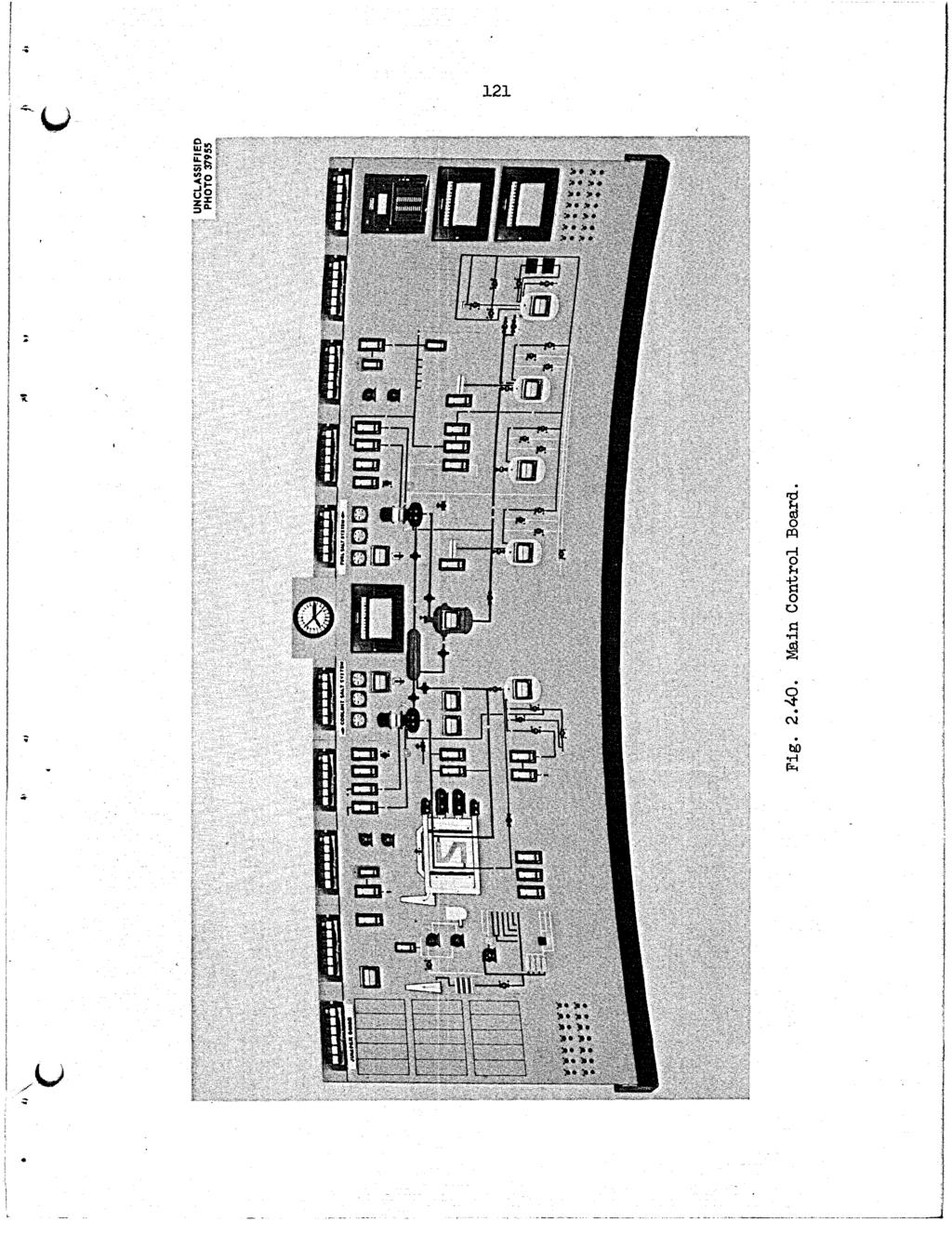
135 . 121
136 122 UNCUSSlFlEO ORNL-OWG JL WLDNG 7503-ELEVATON 840 ft Oin. LEVEL Fig Layout of Building 7503 at 84O-ft Elevation. microphone amplifier and noise level indicator, and the substation alarm monitors. The relay cabinet contains only the relays for the main control circuitry. The thermocouple cabinet contains a patch panel with pyrometer jacks. All thermocouples in the system except those on the radiator tubes are terminated in this cabinet. The five nuclear panels contain some of the instrumentation for the process radiation system, the oil system, and the sampling and enriching system. The health physics monitoring alarm system, the high level gamchamber electrometers and switching panel, and the reactor control nuclear amplifiers, servo amplifiers, and other equipment for the nuclear control system are also located here. Four panels contain the instrumentation for the operation of the emergency diesel generators. The distribution panels
137 123 for the control circuits are located on the south wall of the auxiliary control room Transmitter Room, The transmitter room, Fig. 2.42, consists of nine control panels, one solenoid power supply rack, and a transmitter rack. Panels 1 and 2 are for the leak detectors system, and panels 3 and 4 are for fuel drain tanks 1 and 2, coolant drain tank, fuel Plush tank, and the fuel storage tank weigh instrumentation. Panels 5 and 6 are the fuel and coolant pump bubbler-type level control panels, panel 7 is the freeze valve air control panel, panel 8 is an installed spare panel, and panel 9 is for the sump bubbler system. The solenoid power supply rack contains most of the solenoids for the fuel salt system and the power supplies and distribution panels for the electric transmitters and differential transmitters. The UNCLASSFED ORNL-DWG i xl El LDK c R E M 0 VA B L E ACCESS PLUG TRANSMTTER RACK il Fig Transmitter Room.
138 124 transmitter rack contains the remote amplifiers for the electric signal transmission system and also the current-to-air transducers. All electrical and pnemtic lines that connect transmitter room equipment to input signals from the reactor, drain tank, water room, and all other areas outside the building enter through sleeves in the floor. Output signals from the transmitter room equipment are conducted via feeder cable trays to the main cable tray system, which runs north-south in the building on the 840-ft level Field Panels Additional panels are required for the auxiliary systems. These (see Figs and 2.41) are located near the subsystems which they serve. Four panels for the cooling oil systems are located in the service room and service tunnel: one cooling and treated water system panel is located in the fan house: three panels are located on elevation 852 ft at column line C-7 for the sampling and enriching system. Two cover gas system panels are located in the diesel house. Two containment air system panels are provided. One is located at the filter pit, and the other is located in the high bay area nterconnections The control areas and the controlled systems are interconnected by cable trays and conduit. This system includes the main cable tray system running north-south in the building, with branch trays and conduits joining the main tray. These main trays carry all tubing for the pnematic system, thermocouple leadwire, and the ac and de control wiring. Each category of signal runs in a different tray to avoid mixing of the signals. Risers connect the panels and cabinets in the control area on elevation 852 ft with the main trays. No exposed trays are in the main or auxiliary control rooms. Safety system wiring is completely enclosed in conduit and junction boxes and is separated from control and instrumentation wiring.
139 Data Room The data room (Figs and 2.43) is designed primarily to house the data-handling system, but it also serves as the information processing center for the reactor. The room contains storage space for all types of instrument data and log sheets. t also contains the data-plotting equipment used with the data-handling system and other special data display and processing equipment. This room is located in the north end of the reactor building next to the main control room. There are entries from the hallway and the main control room. A large glass window is located so that the main control panel can be seen from the room. The data-handling system is installed along the west and north walls of the room, Fig The data system console is located so that the reactor control panel can be seen by an oper-ator at the console. At least two desks and several tables are located in the room for use of reactor operations and analysis personnel. Data-plotting equipment and record storage cabinets are placed at ccnvenient locaiions. A typical process computer system is shown in Fig The input signal cables for the data system are brought up to the bottom of the room in cable trays and conduits. Holes are cut in the floor beneath the signal input cabinet for routing the cables to the cabinet. Cable trays and conduit are also provided beneath the floor for signal lines to and from the main and auxiliary control areas. The data room is air conditioned by the system which is used for the control room and offices.

140 126 WCLASSFED ORNL-DG L - NPUT ANALOG *EGyAT NPUT OUTPUT NPUT OUTPUT N0.2 NO. 3 NO. 4 STEM / LANAL~G NO. 4 ACCESSORES - MAGNETC TAPE MAGNETC TAPE PAPER TAPE PUNCH AND REAMR 1 LX-Y PLOTTER Fig Layout of Data Roam. -pz W
141 UNC LASS F ED ORNL- DWG PROGRAMMNG AND MANTENANCE STATON FLEXOWRTER HGH SPEED PAPER TAPE PUNCH HGH SPEED PAPER TAPE READER --.._..., DRUMMEMORY NTERRUPT SUBSYSTEM MASTER NPUT-OUTPUT CONTROL SUBSYSTEM PROGRAMMNG AND MANTENANCE PANEL NPUT-OUTPUT SYSTEM ANALOG NPUT SUBSYSTEM ANA1 - N: - DUTPllT -.. SLJRSYSTEM CONTACT CLOSURE NPUT SUBSYSTEM CONTACT CLOSURE OUTPUT SUBSYSTEM COUNTER SUBSYSTEM OPERATOR-PROCESS COMMUNCATON STATON LOGGNG TYPEWRTER OPERATOR'S CONSOLE CONTROL PANEL DSPLAY NPUT SWTCHES FUNCTON SELECTOR FUNCTON MATRX ALARM PRNTER Fig Typical Process Computer System (TRW-340).
142 PLANT LAYOUT 3.1 Equipment Arrangement The general arrangement of Building 7503 is shown in Figs. 3.1 and 3.2. The main entrance is at the north end. Reactor equipment and major auxiliary facilities occupy the west half of the building in the high-bay area. The east half of the building contains the control room, offices, change rooms, instrument and general maintenance shops, and storage areas. Additional offices are provided in a separate building that is east of the main building. Equipment for ventilating the operating and experimental areas is located south of the main building. A small cooling tower and buildings containing supplies and the diesel-electric emergency power equipment are near the west side of the main building. The reactor primary system and the drain tank system are installed in shielded, pressure-tight reactor and drain tank cells, which occupy most of the south half of the high-bay area. The reactor cell is 24 ft in diameter and 33 ft in height. t is surrounded by a 30-ft-diam steel tank, and the 3-ft annular space is filled with a shielding mixture of sand and water. The top of the cell is covered with removable shielding blocks that extend 3 1/2 ft above the floor elevation of 852 ft and are sealed with a welded rnembrane. Adjoining the reactor cell on the north side is the drain tank cell, which extends 5 ft deeper than the reactor cell to provide gravity flow from the reactor to the drain tanks. This cell is rectangular (17 1/2 X 21 1/2 ft ), with 3-ft-thick heavily reinforced concrete walls lined with stainless steel. Access to the equipment is through the removable roof blocks, which are arranged in two layers with a sealing membrane between. Several other shielded cells are located in the north end of the high-bay area, as shown in Fig They provide shielding and ventilated isolation for the fuel processing cell, the waste cell, and two cells for equipment storage and decontamination. Fig. 1.3 (see see. 1.2) shows how the components of the fuel circulating system are arranged in the reactor cell. The reactor tank and the

143 t *t H E 1 2 UNCLASSFED ORNL DWQ ? R MANTENANCE D FUEL SALT f ADDTON STAT ON Fig First Floor Plan of Reactor Building. \.
144 t n m ho d Fr a
145 131 thermal neutron shield are located south of the center of the containment cell, and they rest on the floor. The primary heat exchanger is positioned north of the reactor vessel and above it in elevation. The freeze flanges on the fuel and coolant salt lines attached to the heat exchanger are placed with adequate working space for remote-maintenance operations. The fuel-circulating pump is mounted east of the reactor vessel and above it and the heat exchanger, so that the free surface of salt within the pump bowl is the highest point in the system. Underneath the bowl is the overflow tank and surrounding it is an electric furnace. All service piping flanges and electrical joints are located close to the pump bowl so that remote replacement of the pump bowl will be easier. The arrangement of the drain tank cell is illustrated in Fig The flush salt tank is at the south end of the cell, and the two fuel salt tanks are north of it. Space is allowed to the east and west for remote cutting and brazing equipment in case either of the tanks must be removed. n the northwest corner of the cell is a 25-kva transformer, which supplies the power for resistance heating of the 1 1/2-in. drain line connecting the reactor vessel to the tanks. The coolant cell abuts the reactor cell on the south. t is a shielded area, with controlled ventilation, but it is not sealed. The coolant salt circulating pump is mounted high in the coolant cell, as shown in Fig The radiator is at a lower elevation, to the west, and confined in the air-cooling duct. The coolant drain tank is underneath the pump and radiator, at the bottom of the cell, The blowers that supply cooling air to the radiator are installed in an existing blower house along the west wall of the coolant cell. Rooms containing auxiliary and service equipment, instrument transmitters, and electrical equipment are located along the east wall of the reactor, drain tank, and coolant cells. Ventilation of these rooms is controlled, and some rooms are provided with shielding. The high-bay area of the building over all the cells is lined with metal to minimize inleakage. Ventilation is controlled and the area is normally operated at slightly below atmospheric pressure. The effluent air from this area and from all other controlled-ventilation areas is
146 132 filtered and monitored before it is discharged to the atmosphere. The w containment ventilation equipment consists of a filter pit, two fans, and a 100-ft-high steel stack. This equipment on the south side of the main building is connected to the building by one ventilation duct to the bottom of the reactor cell and another along the east side of the high bay. The vent house and charcoal beds for handling the gaseous fission products from the reactor systems are near the southwest corner of the main building. The carbon beds are installed in an existing pit that is filled with water and is covered with concrete slabs. The vent house and pit are also controlled-ventilation areas. Gases from the carbon beds are monitored continuously for radioactivity and are discharged into the ventilation system upstream of the filters. 3.2 Biological Shielding The MSRE work areas are divided into five types based on expected radiation levels: (1) areas with high radiation levels that prohibit entry under any circumstances, such as the reactor and drain tank cells; (2) areas that can be entered a short time after reactor shutdown, such as the radiator area; (3) areas that can be entered at low reactor power levels, such as the special equipment room; (4) areas that are habitable at all times; and (5) the maintenance control room, which is the only habitable area on the site when certain large-scale maintenance operations are being performed. The MSRE shielding is designed to permit prolonged operation at 10 Mw without exposing personnel to more than a few mrem per week. The areas which will be entered routinely and will have unlimited access will be essentially at the normal background level for the Oak Ridge vicinity. However, there are several class 2 and class 3 areas which will have activity levels considerably above background and which will be entered only occasionally. These are located near the reactor or drain-tank cell penetrations. One such limited access area is the coolant cell, in which the background activity might be as high as 100 mr/hr. The blower house is also a limited access area, since the radiation level may be about 20 mr/hr near the blowers. Although the special equipment room is considered
147 133 a limited access area, the radiation field should not exceed about 10 mr/hr. The south electric service area, another limited access portion of the building, will have a generally higher radiation level of approximately 200 mr/hr. All these estimates are based on operation of the reactor at the 10-Mw power level. On the infrequent occasions when these areas must be entered, radiation surveys will be made so that the working time and exposures can be kept to safe levels. When the reactor is subcritical, all areas, except those of type 1 (the reactor, drain tank, and fuel processing cells), may be entered a few minutes after the reactor is shut down and after a radiation survey is completed. n general, it is expected that access can be on an unlimited basis unless "hot spots" are found. n any direction from the reactor vessel, a sufficient thickness of shielding material has been provided to reduce the radiation level in habitable areas to background levels. n some directions the shielding exists as several widely separated barriers. The general arrangement is described below, beginning at the reactor vessel. Reactor Cell. The reactor vessel at the south side of the cell is surrounded by a stainless steel tank with a 16-in. thickness of iron and water. This thermal neutron shield is located within the secondary containment vessel which, in turn, is within another tank to provide a 3-ftwide annular space, which is filled with magnetite sand and water. The outer tank is surrounded by a cylindrical, monolithic concrete wall 21 in. thick, except in the area facing the coolant cell. n this area special shielding materials are installed to give equivalent protection. There are no equipment or personnel access openings other than those through the top of the cell.. The top of the reactor cell is flat and is covered with two 3 1/2-ft layers of large, removable, concrete blocks, as shown in Fig The bottom layer is high-density (sp gr = 3+) concrete, and the upper layer is ordinary concrete. The joints in the lower layer of blocks are filled with steel plate inserts. A stainless steel sheet (l/8 in. thick) is sand.wiched between the two layers and is welded to the edge of the tank to provide a gastight seal.
148 134 UNCLASSFED ORNL DWG SECT ON "X X' Fig Arrangement of Shielding Blocks on Top of Reactor.
149 13 5 The service penetrations through the reactor cell walls pass through sleeves filled with magnetite concrete grout or magnetite sand and water. Where possible, these lines have an offset bend. The penetration of the 30-in.-diam air exhaust line through the bottom hemisphere of the containment vessel required special treatment because of the size of the opening. A shadow shield of a 9-in. thickness of steel is provided in front of the opening inside the cell, and a 12-in.-thick wall of stacked blocks is erected outside the cell at the foot of the ramp to the coolant cell. Coolant Cell. The top and sides of the coolant and coolant drain tank cell provide at least 24 in. of concrete shielding as protection against activity induced in the coolant salt while the reactor is producing power. The large openings provided between the coolant cell and the blower house for the cooling air supply to the radiator, however, make it difficult to shield the blower house from this induced activity. Space has been provided for additional shielding in the form of stacked blocks, should they be found necessary after full power is reached. Drain Tank Cell. The drain tank cell has a minimum thickness of 3 ft for the magnetite concrete walls facing accessible areas. The top of the cell consists of a layer of 4-ft-thick ordinary-concrete blocks covered by a layer of 3 1/2-ft-thick ordinary-concrete blocks. The pipe lines penetrating the cell walls have offsets, and the smaller pipes are cast into the walls. Shielded plugs are provided for the larger penetrations. Other Shielding. The 1/2-in. offgas line from the reactor cell to the charcoal beds is shielded by 4 in. of lead as it passes through the coolant drain tank cell. Barytes concrete blocks are stacked to a thickness of 5 ft above the line in the vent house, and 17-in.-thick steel plate is provided above the line between the vent house and the charcoal beds. The charcoal beds are covered with two 18-in.-thick by 10-ft-diam barytes concrete blocks and an additional 30-in. thickness of stacked barytes blocks. The walls of the filter pit for the containment ventilation system are 12 in. thick and the roof blocks over the filters are 18 in. thick.
150 136 The thicknesses of the walls and tops of the auxiliary cells are given in Table 3.1. Additional shielding is provided by blocks stacked on the west side of the fuel processing and the decontamination cells. Equipment in the fuel-circ-dating and drain tank systems will be repaired or replaced with remote-handling and -viewing equipment. A heavily shielded maintenance control room with viewing windows is located above the operating floor. This room will be used as a protected place to operate remotely controlled equipment when several roof shielding plugs are removed and radioactive equipment is to be transferred to a storage cell. Equipment in the coolant cell cannot be approached when the reactor is operating, but the induced activity in the coolant salts is sufficiently short lived to permit the coolant cell to be entered for direct maintenance shortly after reactor shutdown.
151 Table 3.1. Descriptions of Auxiliary Cells Name of Cell Locat ion Concrete Wall Thickness Thickness nside Dimensions Floor of Top N-S E4 N-S x E-W Elevation N S E W Blocks Colwnns Columns (in.) (in.) (in.) (in.) (in.) Fuel processing cell 4-5 A-B 12 ft 10 in. X 14 ft 3 in. 831 ft 0 in. ld 44 18a 12" 48 Decontamination cell 3-4 A-B 15 ft 0 in. x 14 ft 3 in. 832 ft 6 in Liquid waste cell 2-3 A-B 13 ft 0 in. X 21 ft 0 in. 828 ft 0 in Remote maintenance cell 2-3 C-D 13 ft 0 in. X 21 ft 0 in. 831 ft 0 in Hot storage cellb 3-4 C-D 15 ft 0 in. X 14 ft 3 in. 832 ft 6 in " Spare cell 4-5 C-D 13 ft 6 in. X 14 ft 3 in. 831 ft 0 in " 30 %us additional stacked blocks as required. bthe hot storage cell is lined with 11-gage stainless steel to the elevation of 836 ft 6 in.
152 STE FEATURES* 4.1 Location The Molten-Salt Reactor Experiment is located in the Roane County portion of the Oak Ridge area of Tennessee. The site is owned and con- trolled by the Atomic Energy Commission. The MSRE is in the Melton Valley area of the Oak Ridge National Laboratory southeast of the Bethel Valley, X-10 area, in Building 7503, which formerly housed the Aircraft Reactor Experiment (ARE). Building 7500, which formerly housed the Homogeneous Reactor Erperiment No. 2 (HRE) and which is 2000 ft west-northwest of the ERE, now houses the Nuclear Safety Pilot Plant (NSPP). The High Flu sotope Reactor is being constructed 1500 ft south-southeast of the MSRE site. The main laboratory area of X-10, which is approximately 1 mile to the northwest, is separated from the MSRE site by Haw Ridge. Melton Hill bounds the valley on the southern side. The MSRE site is located within a well-established AEC-controlled area. The AM: Patrol covers the roads and adjacent area to restrict public access to certain designated routes through the controlled land. A perimeter fence encloses the entire area of the MSRE. Approximately 40 people will be present in the exclusion area during the day shift and 6 or 7 on the evening and night shifts. The location is shown in respectively increasing scale in Figs. 4.1, 4.2, and Population Density The total population of the four counties (Anderson, Knox, Loudon, and Roane) closest to the MSRE site is 370,145. Of this number, 177,255 people are located in cities with populations greater than 2500 persons. The rural population density in these four counties is about 135 persons per square mile. Th? average population density within a radius of 27.5 miles of the MSRE site, as determined from the data obtained in the 1960 census, is 147 persons per square mile. Table 4.1 lists the surrounding -~ This chapter was compiled by T. H. Row, Reactor Safety Group of the Reactor Division, Oak Ridge National Laboratory.
153 Fig Area Surrounding MSRE Site. P w CJ
154 140 UNCLASSFED ORNL-LR-DWG 4406R Fig Contour kp of Area Surrounding MSRE Site.
155 , $!! i?, , < - - k( * 'c F c
156 Table Population of the Surrounding Towng Based on 1960 Census 0 City Distance or from Sitea Direction Population Town (miles) Time Downwind ($1. Night Day Oak Ridge Lenoir City Oliver Springs Martel Coalfield Windrock Kingston Harriman South Harriman Petros Fork Mountain Esnory Gap Friendsville Clinton South Clinton Powell Briceville Wartburg Alcoa Mary-ville Knoxville Greenback Rockwood Rockford Fountain City Lake City Norris Sweetwater Neubert John Sevier Madisonville Caryville Sunbright Jacksboro Niota to "E SSE 'N by W SE Nw N by W WSW w \ W NW by N NNW W SE NE NE XDE "E NW by W ESE ESE E S by E W by S SE EHE "E "E SSW, ENE E S N by E 'NW N by E SSW 27,124 4,979 1,163 5OOb 650b 550b 2,010 5,931 2, b 7Oob 5OOb 606 4,943 1,356 5OOb 1,217 8OOb 6,395 10, , b 5,343 5,345 10,365 1,914 1,389 4,145 6OOb 752b 1,812, 1,234b 6OOb. 577b d ' ' A Q &Based on data obtained for HFR site.\ btaken from 1950 census..,
157 143 communities with a population of over 500 and their approximate distance and direction from the site. The rural population density in the four surrounding counties is given in Table 4.2. A number of facilities are located within the AEZ-controlled area, and the approximate number of employees at each plant is given in Table 4.3. The numbers of employees indicate the total employment! at each facility and do not attempt to show the breakdown according to shifts. However, most of these employees work the normal 40-hr week on the day shift. Table 4.2. Rural Population in Surrounding Counties county Total Area" (sq. mile) Ruralb Population Population Density (No. people per sq. mile) Estimated Populat i on Within Within Within 10-Mile 20-Mile 30-Mile Radius Radius Radius - ~~ ~~ ~ ~~ Ande r s on , ,200 22,800 Blount , ,720 23,200 Knox , ,100 46, ,000 Loudon , ,080 16,900 18,700 Morgan , ,625 8,630 Roane , ,070 9,170 11,110 - _ - -?Does not include area within Oak Ridge reservation. %960 census; does not include communities with population of 500 or more. An estimate was made of the distribution of the population in each of the 16 adjacent 22 1/2" sectors of concentric circles originating at the MSRE. Seven different distances were considered from the MSRE site: radii of 0 to 1, 1 to 2, 2 to 3, 3 to 4, 4 to 5, 5 to 10, and 10 to 20 miles. The values obtained, given in Table 4.4, are representative of the population in this area at all times. Very little change is experienced due to either part-time occupancy or seasonal variation. The population density in the area has been reasonably stable for a number of years and is anticipated to remain so.
158 144 Table 4.3. Thunber of Employees in Specific Oak Ridge Areas in June 1963 Distance Total Area from Site Direction Number of (miles) Employe e s MSRE NSPP HFR WNW S SE ORYX 3830 HPF3 X-10 area personnel Construction personnel 7000 area personnel Tower Shielding Facility EGCR Melton H ill Dama Construction personnel, June 13% Xormal operation (remotely controlled, K-25 (Gaseous Diffusion Plant) K-25 area personnel Construction personnel Y-12 (Electromagnetic Separations Plant ) Y-12 area personnel OR?& personnel Construction personnel University of Tennessee Agricultural Research Laboratory EUU Run Steam Planta r, c) Nw Nw "E ESE S NE S WNw "E NE NE Construction personnel July 196L December 1964 July 1965 December 1965 Normal operation (one unit ) ?%timated from construction schedules, TVA, Knoxville, Tenn., June 5, 1963.
159 .,. c Table 4.4. Estimated Population Distribution" Radius (miles) - Population in Given Sector - - N NNE NE EXE E ESE SE SSE S ssw SW WSW W W-NW NW NNW O-O G l gob , ,944 20, ,706 7,'706 7, ,546 1,567 1,564 7El ,320 13,318 6,650c 56,414 55,914 23,131 6,388 5,660 4,700 4,700 1,563 3,573 16,741 2,542 1, , E ,190 ancludes Oak Ridge Plants b Does not include Melton Hill Dam, see Table 4.3. 'Does not include Bull Run Steam Plant, see Table 4.3.
160 Geophysical Features Meteorolom Oak Ridge is located in a broad valley between the Cumberland Mountains, which lie to the northwest of the area, and the Great Smoky Mountains, to the southeast. These mountain ranges are oriented northeastsouthwest and the valley between is corrugated by broken ridges 300 to 500 ft high and oriented parallel to the main valley. The local climate is noticeably influenced by topography Temperature' The coldest month is normally JaniJary, but the differences between the mean temperatures of the three winter months of December, January, and February are conparatively small. b-jt differences between the mean temperatures of the summer months of June, July, and August are also comparatively small. Mean temperatures of the spring and fall months progress orderly from cooler to warmer and warmer to cooler, respectively, :ii thoili+, a secondary maximum or minimum. Ter-peratures of 100 F or higher are unusual, having occurred during less than one-half of the years of the period of record, and temperatures of zero and below are rare. July is usually the hottest month, The annual Rean maxinu and minimam temperatures are 69.4 and 47.6"F, respectively, with a? arnjzl :rema temperat.lire of 58.5"F. and high temperatures 8re -5 and 103"F, recgrded in December 1962 and September 1954, respectively. The extreme low Tzble 4.5 lists the average monthly tem- perature range based on \he period 1931 Lo 1960, adjusted to represent observations taken at the present standard location of the weather station. nformation on the texperature gradient frequency and mean wind speed for each month were presented in a recent report2 on the meteorology of 'U.S. Dept. of Commerce, Weather Bureau, Asheville, N.C., Local Climatological Data, 1962, Oak Ridge, Tennessee, Area Station (X-lo), April 23, W. F. Hilsmeier, "Supplementary Meteorological Data for Oak Ridge, " USAEC! Report ORO-199, Oak Ridge Operations, March 1963.
161 147 L Table 4.5. X-io Climatological Standard Normals (1931 to 1960) Maximum Minimum Average Temperature Temperature Temperature J8LlUa-y February March April May June JdY August September October November December Annual the Oak Ridge area. The seasonal and annual averages derived from this information are presented in Fig. 4.4, PreciDitation' Precipitation in the X-10 area is normally well distributed throughout the year, with the drier part of the year occurring in the early fall. Winter and early spring are the seasons of heaviest precipitation, with the monthly maximum normally occurring January to March. A secondary maximum occurs in the month of July that is due to afternoon and evening thundershowers. September and October are usually the driest months. The average and maximum annual precipitation are and 66.2 in., respectively. The maximum rainfall in the area in a 24-hr period was 7.75 in., recorded in September The recurrence interval of this amount of precipitation in a 24-hr period has been estimated to be about 70 years. The maximum monthly precipitation occurs normally in March and has a value of 5.44 in. The average monthly precipitation is given in Table A.6.
162 148 UNCLASSFED ORNL-DWG DAY NGHT n TEMPERATURE GRADENT PER!OO ft (OF) Fig Seasonal Temperature Gradient Frequency.
163 149 Table 4.6. X-10 Average Monthly Precipitation Data Mon-th January February March April May June July August September October November December Precipitation (in. ) Light snow usually occurs in all months from November through March, but the total monthly snowfall is often only a trace. The total snowfall for some winters is less than 1 in. The average snowfall for the period from 1948 to 1961 is 6.9 in. The maximum snowfall in a 24-hr period was 12 in. in March The maximum monthly snowfall, 21 in., also occurred in March The heavy fogs that occasionally occur are almost always in the early morning and are of short duration Wind3 The valleys in the vicinity of the MSRE site are oriented northeastsouthwest, and considerable channeling of the winds in the valley may be expected. This is evident in Fig. 4.5, which shows the annual frequency distribution of winds in the vicinity of 0R.NL. The flags on the wind-rose diagrams point in the direction from which the wind comes. The prevailing wind direct ions are upvalley from southwe st and we st - sout hwe st approxi - mately 40% of the time, with a secondary maximum of downvalley winds from 3W. B. Cottrell, ed., "Aircraft Reactor Experiment Hazards Swnmary Report," USAM: Report ORNL-1407, Oak Ridge National Laboratory, November 1952.

164 150 Fig of X-10 Area. Annual Frequency Distribution of Winds in the Vicinity
165 151 L northeast and east-northeast 30$ of the time. The prevailing wind regimes reflect the orientation of the broad valley between the Cumberland Plateau and the Smoky Mountains, as well as the orientation of the local ridges and valleys. The gradient wind in this latitude is usually southwest or westerly, so the daytime winds tend to reflect a mixing down of the gradient winds. The night winds represent drainage of cold air down the local slopes and the broader Tennessee Valley. The combination of these two effects, as well as the daily changes in the pressure patterns over this area, gives the elongated shape of the typical wind roses. During inversions, the northeast and east-northeast winds occur most frequently, usually at the expense of the southwest and west-southwest winds. The predominance of light northeast and east-northeast winds under stable conditions is particularly marked in the smer and fall when the lower wind speeds aloft and the smaller amount of cloudiness allow the nocturnal drainage patterns to develop. Wind roses prepared from 5 years of data, 1956 to 1960, are shown in Figs. 4.6 and 4.7 (ref. 2). These represent the wind direction, frequency, and percentage of calm under inversion and lapse conditions for the X-10 area and are applicable to the MSRE location. Considerable variation is observed both in wind speed and direction within small distances in Bethel Valley and Melton Valley. t may be said that in nighttime or in stable conditions, the winds tend to be generally northeast and east-northeast and rather light in the valley, regardless of the gradient wind, except that strong winds aloft will control the velocity and direction of the valley winds, reversing them or producing calms when opposing the local drainage. n the daytime, the surface winds tend to follow the winds aloft, with increasing reliability, as the upper wind speed increases. Only with strong winds aloft or winds parallel to the valleys would it be of value to attempt to extrapolate air movements for any number of miles by using valley winds. n the welldeveloped stable situation, however, a very light air movement will follow the valley as far downstream as the valley retains its structure, even though the prevailing winds a few hundred feet above the ground are in an entirely different direction. n a valley location, the wind is
166 152 Unclassified ORNL-DWG WNTER R SPRNG U LAPSE SUMMER FALL,.p Wind sped, mph X Calm N % Frequency Data Fig X-10 Area Seasonal Wind Roses.
167 153 Unclassified ORNL-DWG WNTER 1 SPRNG NVERSl ON SUMMER / FALL /./ 0 ( 4434 obs) c ( 4792 obs ) Wind speed, rnph X. Calm 1 N 9. Frequency Data Fig X-10 Area Seasonal Wind Roses.
168 154 governed by the local valley wind regime and the degree of coupling with the upper winds.3 The wind flow between Melton Valley and the X-10 area was investigated in conjunction with the Aircraft Reactor Experiment (ARE) hazards analy~is.~ Two patterns of wind flow were assumed to be of significance: (1) from the '7500 area northwest over Haw Ridge to the X-10 area, and (2) from the 7500 area west to White Oak Creek, then northwest through Haw Gap, and finally north to the X-10 area. The frequencies of these patterns during the period September to December 1950 were normalized to the to-1951 wind record at the X-10 area by a ratio meth~d.~ The normalized frequencies are listed in Table 4.7. Table 4.7. Frequency of Wind Patterns Between 7500 and X-10 Area Frequency of Wind Pattern ($) Over Ridge Through Gap -411 observations Day (9 arn to 5 pm) might (9 pm to 5 an) Light wind (1 tc 4 ;r-ph) Stronger wind (5 rrph and over) A comparison of the pibal* zbservations made throughout 1949 to 1950 at Knoxville and Oak Ridge shows that above about 2000 ft the wind roses are almost identical at, these two stations. This identity in the data makes possible the use of the longer period of record (1927 to 1950) from Knoxville to eliminate the abnormalit,ies introduced by the use of the short record at Oak Ridge. Annual wind roses are shown for Knoxville (1927 to 1950) and Nashville (193'7 to 1950) in Fig Pibal observations are only made when no clouds, dense fog, or precipitation is occurring and so are not truly representative of the upper wind at all times. *Pilot balloon visual observations.
169 155 L Three years of Rawin* data for Nashville (1947 to 1950) are available that consist of observations taken regardless of the current weather at the time of observation. A comparison of these wind roses for Knoxville and Nashville shows that the mode for winds above 3000 meters mean sea level should be shifted to westerly instead of west-northwest when observations with rain are included in the set. n summer and fall, the winds aloft are lightest and the highest winds occur during the winter months at all levels. The northeast-southwest axis of the valley between the Cumberland Plateau and the Smoky Mountains continues to influence the wind distribution over the Tennessee Valley up to about 5000 ft, although the variations within the Valley do not extend above about 2000 ft. Above 500 ft, the southwesterly mode gives way to the prevailing westerlies usually observed at these latitudes. Previous investigation of the relation of wind direction to precipitation indicates that the direction distribution is very little different from that of normal observation^.^ This is consistent with the experience of precipitation forecasters that there is llttle correlation between surface wind direction and rain, particularly in rugged terrain. Figure 4.8 shows the upper winds measured at Nashville during the period 1948 to 1950, when precipitation was occurring at observation time. n general, the prevailing wind at any given level is shifted to the southwest or south-southwest from west or southwest, and the velocity is somewhat higher during the occurrence of precipitation, with the shift being most marked in the winter. The percentage of inversion conditions of the total hours for the seasons is given in Table 4.8 (ref. 2). Tornadoes rarely occur in the valley between the Cumberland and the Great Smokies. t is highly improbable that winds greater than 100 rnph would ever be approached at the MSRE site. *Radio wind balloon observations.
170 156 KNOXVLLE PBAL NASHVLLE PBAL NASHVLLE RAWN ALL OBS. UNCLASS F ED DWG NASHVLLE RAWN P REClP TATON 500m Obi 3341 Obs 4, L 3 rv / 239 Obr 1500m Obr Obr 3269 Obr 227 Ob. 3000m Ob, Obr 3193 Obr 217 Ob% 6000m 3692 Ob, 2964 Obr 2684 Obr 170 Obi OOOOm 536 Ob, 717 Obr Obi Y. Calm W-d Speed M PH? Frequency i 54-56_5p3_s-+ O lzzd aappr-- ~ PBAL -PLOT RAWN-RADO BALLOON VSUAL OBSERVATONS WND BALLOON OESERVATONS Fig tudes. Wind Roses at Knoxville and Nashville for Various Alti-
171 157 Table 4.8. Summary of Seasonal Frequency of nversions Season Winter Spring Summer Fall Annual Frequency of nversion (% Average Durationa (hr) ~ ~~ "w. M. Culkowski, AEC, Oak Ridge, personal communication to T. H. Row, Oak Ridge National Laboratory, July 8, Atmospheric Diffusion Characteristics Sutton1s4, methods of calculating the dispersion of airborne wastes require a knowledge of several meteorological parameters. Values of these parameters of the X-10 site were recommended by the Oak Ridge Office of the U.S. Weather Bureau6 and are listed in Table 4.9. They provide a '0. G. Sutton, "A Theory of Eddy Diffusion in the Atmosphere," hoc. ROY. SOC. (Londonj, G. Sutton, Micrometeorology, McGraw-Hill Co., nc., New York, "Final Hazards Summary Report, Experimental Gas -Cooled Reactor, ' Vol. 1, Book 1, pp. 3-6, USAEC Report ORO-586, Oct. 10, Table 4.9. Meteorological Parameter Values for Atmospheric Dispersion Calculations Parameter Lapse nversion (weak) Mean wind velocity,. (m/sec) Stability parameter, n Diffusion constant, C (mn2) Y Diffusion constant, C_ (mn/*)
172 158 reasonably conservative basis for the dispersion calculations in Section and Appendix C; however, it is recognized that extreme meteorological conditions will occasionally exist and could produce exposures greater than those based on the values in the table Ehvironmental Radioactivity Atmospheric contamination by long-lived fission prcducts and fallout occurring in the general environment of the Oak Ridge area is monitored by a number of stations surroanding the area. This system provides data to aid in evaluating local conditions and to assist in determining the spread or dispersal of contamination should a major incident occur. Data on the environmental levels of radioactivity in the Oak Ridge area are given in Tables 4.10, 4.11, 4.12, and 4.13 (ref. 7). These levels of activity are, of course, strongly influenced by the radioactive wastes discharged by the various facilities at ORNL. The?ERE will normally release only the gaseous wastes xenon and krypton at rates of 2.5 and 6.4 curies/day, respectively, and thus should not make a significant contribution to the existing activity levels Geology and Hydrology The bedrock beneath the bere site is a dark gray calcareous clay shale with a bearing value zf 6 ;ons/ft2 when unweathered. The overburden on this fresh unweathered shale averages 20 ft in thickness and consists of a ;hin blame: of drganic tcpsoil, generally less than 1 ft in thickness, cn top of weathered shale. The latter, if confined, has a bearirg valae of 3 tons/ft2. The strata of the shale are highly folded and fadted, and the dip, altno-ah it averages about 3.5" toward the south, is irregular and may vary from horizontal to vertical. The Melton Valley in which the NSRE is located is underlain 'cy the Conasauga shale of the Middle and Upper Cambrian Age. The nore resistant rock layers of the Rome formation, steeply inclined toward the southwest, are responsible for Haw Ridge, which parallels the valley immediately to the northwest. 7J. C. Hart (ea.), "Applied Health Physics Annual Report for 1962," USAM: Report ORNL-3490, Oak Ridge National Laboratory, September 1963.
173 looo i Table Concentration of Radioactive Materials in Air in 1962a / Number of Particles (in dis- Long-Lived integrations per 24 Number of hr) Total Number Station Location Activity by Activity Rangesb Number of Particles Per (PC/CC) Particles ~ ft3 ~ io >107 HP-1 HP-2 HP -3 He-4 HP-5 W-6 HP-7 HP-8 E-9. HP-10 S 3587 NE 3025 sw 1000 W Settling Basin E 2506 SW 3027 W 7001 Rock Quarry N Bethel Valley Rd. W 2075 Laboratory Area x 10-l~ Average Perimeter Area , 1.6, HP-31 HP-32 He-33 HP-34 HP-35 HP-36 HP-37 Kerr Hollow Gate Midway Gate Gallaher Gate White Wing Gate Blair Gate Turnpike Gate Hickory Creek Bend Average Remote Area HP-51 Ngrris Dam HP-52 LoUdo~nDam HP-53 ' Douglas Dam ' HP-54 Cherokee Dam HP-55 Watts Bar Dam HP-56 Great Falls Dam He-57 Dale Hollow Dam 38 17l w 172 Average a Averaged weekly from filter paper data bdetermined by filtration techniques.
174 ~ 14, 160 Table Radioparticulate Fallout in 1962a Number of Particles (in disbng-lived integrations per 24 hr) Total Total Station Location Activity by Activity Ranges Number of Particles Nder (w/fi2) Particles per ft2. a >lo7 Laboratory Area - Hp-1 Hp-2 Hp-3 Hp-4 EP-5 HP-6 Hp-7 Hp-8 ' Hp-9 Hp-10 S 3587 NE 3025 sw lo00 W Settling Basin E 2506 SW 3027 w 7001 Rock Quarry N Bethel Valley Rd. W 2075 Average x 10-l~ Perimeter Area "-31 "-32 Hp-33 HP-34 Hp-35 Hp-36 Hp-37 Kerr Hollow Gate Midway Gate Gallaher Gate White Wing Gate Blair Gate Turnpike Gate Hickory Creek Bend Average W , 48 Remote Area HP-51 Hp-52 HP-53 HP-54 EP-55 Hp-56 He-57 Norris Dam Loudom Dam Douglas. Dam Cherokee Dam Watts Bar Dam Great Falls Dam Dale Hollow Average n aaveraged weekly from grmrmed-paper data.
175 161 Table Concentration of Radioactive Materials in Rain Water in 1962" St at ion Number Locat ion Activity in Collected Rain Water (PC/CC ) HP-7 Laboratory Area West x HP-32 HP-33 HP-34 Hp-35 Hp-36 HP-37 Perimeter Area Kerr Hollow Gate Midway Gate Gallaher Gate White Wing Gate Blair Gate Turnpike Gate Hickory Creek Bend Average Remote Area HP-51 Norris Dam 14 KP-52 Loudoun Dam 11 HP-53 Douglas Dam 13 KP-54 Cherokee Dam 11 HP-55 Watts Bar Dam 14 HP-56 Great Falls Dam 16 w-57 Dale Hollow Dam 11 Average 13 a Averaged weekly by stations.
176 Table Radioactive Content of Clinch River in 1962 Average Concentration of Nuclides of Primary Concern Concentrat ion Radioactivity Locat ion (PC/CC) of Total (mc) a as Percentage sr90 ~ ~ 1 4 ~ 4 ~ 1 3 ~~ coco zr95*95 Radioactivity (PC/CC 1 of (mc), - x 10-8 x 10-8 x 10-8 x 10-8 x 10-8 x 10-8 x 10-8 x Mile (b Mile P To Mile 4.gd %eighted average maximum permissible concentration (WC )w calculated for the mixture by using values for specific radionuclides recommended in NBS Handbook 69. bnone detected. %slues given for this location are calculated values based on the levels of waste released and the dilution afforded by the river. dcenter s Ferry (near Kingston, Tennessee, just above entry of the Eolory River into Clinch River).
177 163 These layers dip beneath the shales of the Conasauga group in Melton Valley. The shale layers in the area are in keeping with the general structure of the surrounding area, as reported in a geological survey of the area.8 Conasauga shale, a dark red shale, contains thin layers and lenses of limestone that are generally irregular in distribution. However, there are no persistent; limestone beds in the upper strata of the shale layers and, consequently, no underground solution channel or cavern to permit rapid and free underground discharge of water. The dominantly clay soils of the Oak Ridge area are generally of low permeability, so the surface runoff of water is rapid. Observations in test wells show that the Conasauga shale, although relatively impermeable, is capable of transmitting small amounts of water through the soil a distance of a few feet per week. Furthermore, all the active isotopes, except ruthenium, apparently become fixed in the immediate vicinity of the point of entry into the soil. t is concluded that such ground water flow as my exist below the surface in the soil surrounding the site will be small and slow (a few feet per week) and that natural chemical fixation will reduce the level of the activity of mixed, nonvolatile fission products more than 90%. The Conasauga shale formation is extensive, quite heterogeneous in structure, and relatively low in permeability. The depth and extensiveness of the formation provide a large capacity for decontamination of any contaminated liquid reaching it, and the slow rate of percolation improves the efficiency of the decontamination by ion exchange and radioactive decay. However, the heterogeneity of the formation makes difficult the prediction of pattern and rate of movement of water and hence of the fission products contained therein. Most of the seepage is along bedding plains parallel to the strike. Storm drains for the MSRE site will discharge into Melton Branch. The area storm sewers consist of two individual trunk systems. One trunk 8p. B. Stockdale, "Geologic Conditions at the Oak Ridge National Laboratory (X-10 Area) Relevant to the Disposal of Radioactive Waste, ' USAM: Report ORO-58, Oak Ridge Operations, August 1951.
178 164 system empties directly into Melton Branch (see Fig. 4.5) through a connecting ditch; the second trunk system combines with the cooling tower blowdown and the flow from the process waste pond before discharging into Melton Branch through a connecting ditch. The storm drainage system is based on a runoff coefficient of 30% for unpaved or seeded areas. The high runoff coefficient applied to the unpaved areas is justified by the highly impervious character of the soils present in the plant area. Downstream from ORNL, numerous uses are made of the Clinch River water by both municipalities md industries, as indicated in Table The first downriver water consumer is the K-25 plant, whose water intake is located at river mile Representative flows of the Clinch, Emory, and Tennessee Rivers are listed in Table The local flow pattern in the Watts Bar reservoir during the period May through September is significantly affected by the differences in water temperature of the Clinch River and the Watts Bar reservoir. When the Clinch River is considerably cooler, stratified flow conditions caused by density differences may exist, with the cooler water flowing on the bottom beneath the warmer water. This phenomenon mrkedly affects the travel time of water through the reservoir and complicates the analysis of flow. n addition, during the period of stratified flow, some Clinch River water may flow up the Emory River as far as the Harriman water plant intake Seismology nfomtion on the frequency and severity of earthquakes in the Fast Tennessee area is reported in the ART Hazards Report. Earthquake forces have not been considered in the design of facilities at ORNL or TVA structures in the East Tennessee area. The Oak Ridge area is currently classified by the U.S. Coast and Geodetic S7xvey as subject to earthquakes of intensity m-6 measured on the modified Mercalli ntensity Scale. 9W. B. Cottrell et al., "Aiycraf; Reacsor Test Hazards Summary Report, '' USAE Report ORNL-1535, Oak Ridge National Laboratory, January 1955.
179 Table Community Water Systems in Tennessee Downstream from ORNL Supplied by ntakes on the Clinch and Tennessee Rivers or Tributaries" Community Population ntake Source Stream Approximate Locat ion Remarks ORGDP - K-25 Area Harrimn 2, 67%b 5,931' Clinch River Emory River CR Mile 14 ER Mile 12 ndustrial plant water system Mouth of Emory River, CR Mile 4.4 Kingston Steam Plant 50' Clinch River CR Mile 4.4 (TVA 1 Kingston 2, OOOd Tennessee River TR Mile 570 River used for supplementary sup- PlY Watts Bar Dam (resort village and TVA steam Plant 1 Dayton Cleveland Soddy Chattanooga 1, OOOd 3,500' 16,196' 2, OOOd 130, 009' Tennessee River Richland Creek Hiwassee River Tennessee River Tennessee River TR Mile 530 RC Mile 3 HR Mile 15 TR Mile 488 TR Mile 465 Opposite TR Mile 505 Mouth of Hiwassee River is at TR Mile 500 Metropolitan area served by City Water Company South Pittsburg Total 4, 130' 168,061 Tennessee River TR Mile 435 a EGCR Hazards Summary Report, USAEC Report 0R0-586, Oak Ridge Operations, Oct. 10, bbased on May 1963 data. C 1960 Report of U.S. Bureau of the Census. dbased on published 1957 estimates.
180 Table Flows in Clinch, Jhory, and Tennessee Rivers, a Flow (cfs) Clinch River Wry River, Tennessee River Miles 20.8 and 13.2 Mile 4.4b Mile 12.8 Mile Mile Maximum Mean Minimum Maximum Mean Minimum Maximum Mean Minimum Maximum Mean Minimum Maximum Mean Minimum JanUary 22,900 8, %O ,700 14, , OOO ,000 47,700 15, ,000 63,900 23,200 February 27,700 10, ,800 15, , ,000 50,800 17, ,000 67,900 19,700 March 12,700 5, ,700 9, , ,000 32,400 13, ,000 44,200 19,500 April 8,540 3, ,300 5, , ,700 23,800 5,200 82,000 27,700 6, 6Wc 9,730c 2520C 34,900c 45,900c 13,200 WY 8,080 2, ,700 4, , ,300 20,000 3, ,900 28,800 17,900 June 7,420 2, ,280 3, , ,100 18,900 8,200 32,800 25,500 18,900 Jay 7,630 2, ,800 3, , ,500 19,600 6,m 106,OOO 26,400 15,400 August 8,390 4, ,760 4, , ,600 21,400 9,900 43,300 28,100 17,800 September 8,450 4, u, 000 4, , ,900 22,200 6,900 54,400 30,100 3,530a 4,23$ 553d 20,40$ 27,8d 17,100 October 9,200 5, e 14,200 5,300 l5@ 5, ,100 23,500 9,800 72,800 29,700 16,300 November 12,700 4, ,500 5, , ,000 25,400 10, ,000 34,000 13,600 December 27,000 8, ,300 11, , ,000 41,000 11,800 l39,ooo 53,600 21,100 Hazards slllmaary Report, USAEC Report ORO-586, Oak Ridge Operatione Office, Oct. 10, Flow data were collected prior to construction of Melton HFl Dam on Clinch River. Although current data are not available, flow are not expected to be significantly changed. bfl~ shown for Clinch River Mile 4.4 nclude Emory River flows. Nonstratified flow period. dstratified flow period. e By agreement with TVA, a flow of not less than 150 cfs has been maintained in the Clinch River at Oak Ridge since August 28,
181 167 L Both Lynch' of the Fordham University F'hys ics Department and Moneymakerll of the Tennessee Valley Authority indicate that the earthquakes that occasionally occur in the East Tennessee area are quite common in the rest of the world and are not indicative of undue seismic activity. An average of one or two earthquakes a year occurs in the Appalachian Valley from Chattanooga to Virginia according to TVA records. The maximum intensity of any of these shocks recorded is 6 on the Woods-Neuman Scale. A quake of this magnitude was experienced in the Oak Ridge area on September 7, 1956, and was barely noticeable by either ambulatory or stationary individuals. Structures were completely unaffected. Disturbances of this type are to be expected only once every few years in the Oak Ridge area. The Fordham University records indicate a quake frequency below that estimated by TVA. However, the magnitude of the observed quakes is approximately the same. Lynch indicates that "it is highly improbable that a major shock will be felt in the area (Tennessee) for several thon- sand years to come. " lketter from. J. Lynch to M. Mmn, November 3, 1948, quoted in a report on "The Safety Aspects of the Homogeneous Reactor Experiment, " USAE Report ORNL-731, Oak Ridge National Laboratory, June lb. C. Moneymaker, Tennessee Valley Authority, personal communication to W. B. Cottrell, Oak Ridge National Laboratory, October 1952.
182 COXSTRUCTON, STAET UP, AND OPEFATON 5.1 Ccnstructior Although no special constructizn practices were employed in assembling the MS,W, many special precautixs were taken to ensure 3 highquality, clean, and leak-tight assembly. A detailed specification requiring better Quality contrcl than that cf existing commercial ccdes was prepared for each compsnent of the system. Nondestructive inspection techniques, such as ultressnic testing, dye-penetrant inspection, x-ray examination, and helium leak testing, were employed at each fabricator s plant under the supervision cf ORBL inspectcrs. Assembly at the reactor site is being examined similsrly. After completion, the separate systems will be leak tested using rate-cf-pressure rise, mass-spectrometer, and isotcpic-tracer techniques. Durir,g the last stsges cf ccnsrruction and fcr several weeks after ccnstructiin is ccnfleted, Lhe rea:t?r equipment xi11 be checked cut fcr accepthnce by the Operations Depr-rtment. The ind;vidual systems, that is, the cover gx, offgas, pump cil, ccoling iiater, ccmponent air-coding systems, etc.,.,ill be Lperated f;:- the first time. Remcte mintenance will be practiced during this period also. The successive steps in the startup of the reactor are listed in Table 5.1. The most important phases are discussed below. 5.2 Flush- Salt Operat ion t is pl3rlned tr demcnstrate the mechanical perfcrmance cf t.e :<ssembled resctcr by t several-mcnth period cf testing with 3?lush st-lt in the fuel system. Simultsneously, cczlmt salt will be circulated in the ccolant system. Each piece cf equipment will be examined tc determine whether it perfcrms as designed, insofar as this can be determined without nuclear heat generstion. The flush salt will slso serve to scavenge oxygen and to remove other impurities. Another important benefit of the flush-salt test will be the develcpment of the operating skills necessary fcr satisfactory contrcl of the system variables. Heat-balance methods
183 169 Table 5.1. ERE Startup Plans -~ Startup Phase Month Y Complete React or ns tallat i on 0 Operator and Supervisor Training 1-6 Equipment Checkout - Without Salt Heaters, thermocouples, instruments, and logger 2. Cover-gas, offgas, pump-oil, cooling-water, component-aircooling, and radiator-cooling systems 3. Air-compressor, containment-ventilation, diesel-power, and electrical sys terns 4. Remote maintenance Flush Salt Operation Coolant and flush-salt loading, inventory, and transfer methods 2. Coolant-circulating system 3. Fuel-circulating system 4. Sampling and leakage detection 5. Heat-balance methods, heat-removal systems, and temperature control 6. Graphite examination Precritical Shutdown Chemical plant performance (hydrofluorination of flush salt) 2. Loading of fuel salt 3. Completion of nuclear instr-mentation and control-rod tests 4. Final maintenance Critical Experiments Check performance of nuclear instrumentation 2. Load fuel to critical 3. Measure pressure and temperature coefficients of reactivity, control-rod worth, response to flow changes 4. Establish baselines for determination of effects of power on chemistry, corrosion, and nuclear performance Postcritical Shutdown 1. Seal-weld membranes on reactor and drain tank cells 2. Final check on containment leakage 3. Fill and check out vapor-condensing system Approach to Full Power 1. Heat balances, heat-removal control 2. Shield and containment surveys 3. Sampling program for chemistry, etc. 4. Measurement of power coefficient, xenon poisoning, fuel permeation of graphite, and offgas composition 5. Reactor control and logger performance
184 170 and temperature control will be practiced, and sampling operations will be tried. After the flush-salt operating period of one to three months, the flush salt will be transferred tc the chemical plant, where it will be treated tc remove accumulated oxides in a trial performance of the chemical plant. While the reactor system is shut down, the fuel salt will be lcaded into cne cf the drain tanks, with about two-thirds of the U235 estimated for criticality, and the multiplication of the fuel will be measured at several liquid levels. Also during this shutdown, nuclear instrumentation and contrcl rods will be given a final checkout, and remotemaintenance practice Till be completed Critical Experiments After the reactor system has been heated to 1200 F and neutron counting rates have been measured with the reactor empty, the fuel mixture, with about twc-thirds cf the final U235 concentration, will be slowly transferred to the reactcr. Ccunting rates will be determined with the control rods in varicus positions end at several temperatures. f criticality is not attained, the fuel salt will be drained and more U235 will be added and mixed with the original salt before refilling the core. This prccedure will be repeated after every fuel addition. When the counting rates indicate that criticality is near, further fuel additions will be made in approxlmately 10C-g increments at the fuel-circulating pump through the sampling mechanism. When the critical mass has been determined, the temperature and pressure ccefficients will be measured, and the ccntrol-rod calibrations will be completed. btext, the effective fraction of delayed neutrons will be studied to learn the fraction lost by circulation. The reactor must be cperated at zerc power for a pericd of one to three months to establish baselines fcr determinatix of the effects of power operation on salt chemistry, corrcsion, and nuclear perfsrmance Power Operation When the baseline data at zero power are judged to be satisfactory, the power will be increased in increments of several hundred kilowatts
185 171 W over a period of six to ten weeks. At each successively higher power, samples will be collected and measurements will be made of heat output, power coefficient, radiation levels inside and outside shielding, xenon poisoning, offgas composition, and possible permeation of the graphite by fuel. 5.3 Operations Personnel The operation of the MSRE facility will be the responsibility of the Reactor Division Operations Department. The previous assignments of per- sonnel. in this group include the construction, startup, and operation of fcur other experimental reactors: the Low-ntensity Test Reactor, the Homogeneous Reactor Experiments 1 and 2, and the Aircraft Reactor Experi- ment. The experiment will be conducted on a three-shift basis, employing four operating shifts and a day staff for reactor analysis and planning. The organization chart is shown in Fig Each of the four shifts will be headed by a senior-level supervisor for the first few months. A junior engineer and three or four nontechnical operators, many with the previously mentioned reactor experience, will complete the shift organization. The Reactor Analysis Group will be composed of four to six engineers with broad experience in fluid-fuel reactors. ts function will be prin- cipally to plan, supervise, and analyze the experimental program. Over the years this organization has developed training, operating, 1 emergency, and maintenance practices that especially contribute to ex- perimental reactor safety. The same methods and policies will be applied to the Molten-Salt Reactor Experiment. 'R. H. Guymon, "MSRE Design and Operations Report, Part V, Operating Procedures, ' USAEC Report ORNL-TM-908, Oak Ridge National Laboratory, to be issued. 2R. H. Guymon, "MSFE Design and Operations Report, Part X, Safety Procedures and Emergency Plans, USAEC Report ORNL-TM-909, Oak Ridge National Laboratory, to be issued. 3E. C. Hise and R. Blwnberg, "MSRE Design and Operations Report, Part X, Maintenance Equipment and Procedures, " USAEC Report ORNL-TM-910, Oak Ridge National Laboratory, to be issued.
186 UNCLASSFED ORNL DWG SECRETARY OPERATONS CHEF ANALYSS CHEF MANTENANCE AND DESGN CHEF A -SH FT SUPERVSOR ASSSTANT SUPERVSOR COMPUTER r 4 NUCLEAR ENGNEERS (4) TECHNCAN PROGRAMMER NSTRUMENT ENGNEER t-' id TECHNCANS (3) t E- SHFT SUPERVSOR ASSSTANT SUPERVSOR TECHNCANS (3) C-SHFT SUPERVSOR ASSSTANT SUPERVSOR TECHNCANS (3) CHEMST TECHNCAN CHEMCAL ENGNEER TECHNC AN M ETALLURG ST MANTENANCE ENGNEER DESGN ENGNEER 1 PROCUREMENT AND PLANNNG EN GN E E R TECHNCANS (2) D-SH FT SUPERVSOR ASSSTANT SUPERVSOR TECHNCANS (3) t Fig Reactor Division, Operations Department Organization for the MSRE.
187 173 n addition to the capabilities of the Operations Department personnel, the Reactor Division can provide assistance as needed from its larger Design, Development, Analysis, Engineering Science, and rradiation Engineering Departments. Also, other ORNL research and service divisions are participating in many aspects of the MSRF, program. The engineers and technicians assigned to the MSRE operating group are prepared for their duties as reactor supervisors and operators by a combination of formal classroom work and inservice training. The first undertaking is a two-week period devoted exclusively to lectures and instruction on reactor physics, chemistry of salts, MSRE design, nuclear instruments, etc. Next, the candidates are assigned to work on circulating-salt loops, a research reactor, or engineering developments, depending on the candidates previous experience. The next assignment is at the MSRE to assist in calibrations, checkout, and startup of equipment. Following these tasks the personnel will be organized into shift teams to begin operation with molten salt in the reactor systems. At the end of the several months period of circulating hot salt, both the reactor and the operators should be ready for the uranium loading and the initial critical experiment. However, during the maintenance period (approximately one month) prior to criticality, all the operating teams will be given a refresher series of lectures and an examination to conclude the eight-month training program. 5.4 kintenance The maintenance practices to be employed on the MSRE are the outgrowth of several years of experience in repairing and replacing parts of the earlier fluid-fuel reactors, the ARE, RE-1, and HRE-2. Basically the system of maintenance makes use of long-handled tools manipulated by hand through special shielding. After a fault has been discovered, the reactor will be shut down, drained of salt, and cooled. previously prepared procedures modified, if necessary, to cover not only the repair details but safety precautions also. Plans for the repair will be made and When the system is cool,
188 174 a hole will be cut in the top sealing membranes at a location directly above the faulty equipment. The maintenance shield will be set in place and manipulated to permit removal of the shielding blocks below the membrane. Next, the faulty part will be disconnected, using tools through the special shield. f the faulty part is highly radioactive and must be removed from the reactcr cell, the operators will retire to the shielded maintenance control room from which the building crane can be operated remotely to remove the part and store it in a safe place. The operators can then return to the area above the cell and install the new part, using the special shield. Viewing windows and remote television are available to assist the operators in all these procedures.
189 PART 2. SAFETY ANALYSES
190 V
191 CONTANMEKC 6.1 Genersl Desigp Considerations Y t is required that the containment be adequate to prevent escape of large amounts of radioactivity to the surrounding area during operation and maintenance and in the event of any credible accident. The containment must also prevent the release of dangerous amounts of other hazardous materials and, in general, serve to protect personnel and external equipment from damge. Any equipment that contains or could contain multicurie amounts of radioactive material must be surrounded by a minimum of two barriers to prevent escape of the radioactivity. During operation of the MSRE, the first barrier, the primary container, consists of the walls of the various components in the system and the connecting piping. The reactor and drain tank cell enclcsures provide the secondary containment. These cells are normally operated at subatmospheric pressure to assure inleakage. The controlled ventilation areas in the high bay and in the varicus cells constitute a third barrier tc the escape of activity during normal operation of the reactor. Air is drawn from the enclosed areas that are at subatmospheric pressure, passed through absolute filters, and monitored fcr radioactivity before discharge from the 100-ft-high ventilation-system stack located south of Building When the reactor or drain tank cells are opened for maintenance, air flows through the openings at velocities in excess of 100 fpm and substitutes as the secondary barrier. The controlled ventilation area of the high bay above the cell is still the third barrier. However, if the primary piping in the cell is opened for maintenance, the air flow through the cell opening becomes the primary barrier and the controlled ventilation area becomes the secondary containment. h the hypothesis of the maximum credible accident (see see. 8.5), in which it is assumed that hot fuel salt mixes with the water in the cells to generate steam, the total pressure in the containment vessels
192 cculd exceed the design value of 4C psig, if not controlled. condensing system is therefore provided that can rapidly condense the steam and also ret2in ;he ncnccndenshble gsses. A vapor- During normal operaticn, the atmosphere in the reactor and drain tank cells is maintained 2s an inert mixture (95% J2, 51% 02) to eliminate hazards from combustion of flamreble mterizls in the cell, such as the cil in the lubricaticn,system of the fuel circulating pump. The werall leak rate cf the entire primary system is expected to be less than 1 em3 of salt per da;- under normzl cperating conditions. system is cf all-welded c,nstructicra, and all flanged joints are monitored for leakage; a few,jcicts at the least vulnerable locations have autoclave- type fittings. secondary containment) hcve check s-alves or air-operated block valves or both which are ccntrolled by radiaticr, m2nitcrs or pressure switches that can sense z rise in cell pressure. The pcrtion of this piping oxtside the cell, the p>rti,ii between the cell w~ll penetntion and the check or blcck mlve, qlr,d the valtree are enclosed t- provide the required seccnd- kry ccntcimtrt. Pipe lines that pass thrcugh the cell walls (i. e., the These zaxili3rf enclosures are designed to withstand the sxne mzxiwm pressilre (4C' pslg) as the reactor and drain tank cells. The Yea-tcr Cell Pesign The reactzr cell, skown in Fig. E.1, is a cylindrical carbcn steel vessel 2L ft in dikneter anc 33 't in e?-erall height that has 3 hemispherical bottom a:id a flzt tsp. Tlze lcwer 24 1/2 ft was built for the ART in t was originally designed according to Section V11 of the ASME Boiler and Pressure Vessel Code for li75 psig at 565 F and w2.s tested hydrostatically at 303 psig.' The hemispherical bottom is 1 to 1 i/4 in. thick. The cylindrical portion is 2 in. thick, except for the section that contains the large penetrations, diich is 4 in. thick. This vessel was modified fer the T4Sm in 1962 by lengthening the cylindrical secticn $ 1,'2 ft.?ever-1 new penetr-tions were installed, 'W. F. Ferguson et al., "Termination Report for Ccstruction of the ART Facility, " USA.EC Repcrt OJ3KL-2465, Oak Ridge Naticnal aboratory, Nov. 21, 1958.
193 5 179
194 and a 12-in. section of &in. sched-80 pipe closed by a pipe cap was welded into the bottom of the vessel to form a sump. The extension to the vessel is 2 in. thick, except for the top section, which was made as a 7 1/4- by 14-in. flange for bolting the top shield beams in place. The flange and top shield structure are designed to withstand a pressure of 40 psig, and the completed vessel was tested hydrostatically to 48 psig, measured at the top of the cell. Both the original vessel and the extension are made of ASTM A201, grade B or better, fire-box-quality steel. All the welds on the reactor cell vessel were inspected by magnetic particle methods, if they were in carbon steel, or by liquid penetrant methods, if they were in stainless steel. All butt welds and penetration welds were radiographed. After all the welding was completed, the vessel was stress relieved by heating to between 1150 and 1200 F for 7 1/2 hr. The top of the cell is constructed of two layers of 3 1/2-ft-thick reinforced-concrete blocks, with a stainless steel membrane between. The top layer is crdinary ccncrete, with a density of 150 lb/ft3, and the bottom layer is magnetite concrete, with a density of 220 lb/ft3. The blocks in both layers run east and west. To aid in remote maintenance, the bottom layer is divided into three rows of blocks. Blocks in the outer rows are supported on one end by a 13- by 4-in. channel-iron ring welded to the inside of the cell wall. Two 36-in. beams provide the rest of the support fcr the bottom layer of blocks. These beams have angle-iron and steel-plate stiffeners. The cavities are filled with concrete for shielding. The beams rest on a built-up support plate assembly, which is welded to the side of the cell at the 847-ft 7-in. elevation. Offsets 6 1;4 by 26 in. are provided in the ends of the bottom blocks to fit over the support beams. Guides formed by angle iron assure proper alignment. Several of the bottom blocks have stepped plugs for access to selected parts of the cell for remote maintenance. The sides of the blocks are recessed 1/2 in. for 14 in. down from the top. With blocks set side by side and with a 1/2-in. gap between, a 1 1/2-in. slot is formed at the top. One-inch-thick steel plates 12 in. high are placed in the slots for shielding. The 11-gage, ASTM-A24O, type 304 stainless steel membrane is placed on top of the bottom layer of blocks 4
195 L and is seal welded to the sides of the cell. Cover plates are provided over each access plug. These are bolted to the membrane and are sealed by neoprene O-rings. A l/g-in. layer of Pksonite is placed on top of the membrane to protect it from damage by the top layer of blocks. The top blocks are beams that reach from one side of the cell to the other. The ends of these blocks are bolted to the top ring of the cell by fifty 2 1/2-in. studs, 57 1/4 in. long, made from ASTM-A320, grade L7, bolting steel. These studs pass through holes that were formed by casting 3-in. sched-40 pipes in the ends of the blocks. The reactor cell vessel is installed in another cylindrical steel tank that is referred to here as the shield tank. This tank is 30 ft in diameter by ft high. The flat bottom is 3/4 in. thick, and the cylindrical section is 3/8 in. thick. The shield tank sits on a reinforced concrete foundation, The reactor vessel cell is centered in the shield tank and is supported by a 15-ft-diam, 5-ft-high cylindrical skirt made of 1-in.-thick steel plate reinforced by appropriate rings and stiffeners. The skirt is joined to the hemispherical bottom of the reactor cell in a manner that provides for some flexibility and differential expans ion. The annulus between the shield tank and the reactor cell vessel and skirt is filled with magnetite sand and water for shielding. The water contains about 200 ppm of a chromate-type rust inhibitor, Nalco-360. A 4-in.-diam overflow line to the coolant cell controls the water level in the annulus. The region beneath the reactor cell vessel inside the skirt contains only water, and steam will be produced there if a large quantity of salt is spilled into the bottom of the reactor cell (see see. 8.6). An 8-in.- diam vent pipe, which has a capacity for three times the estimated steam production rate, extends from the water-filled skirt area under the vessel to the coolant cell, where the steam would be vented. Numerous large sleeves are required through the walls of the reactor cell and shield tank to provide for process and service piping, electrical and instrument leads, and for other access. The 4- to 36-in.4iam pipe sleeves are welded into the walls of the reactor cell and the shield tank.
196 182 Since the temperature of the reactor cell will be near 150 F when the reactor is operating and the temperature of the shield tank may at times be as low as 60CF, bellows were incorporated in most of the sleeves to permit radial and axial movement of or-e tsnk relative to the other without producing excessive stress. The bellows are covered to prevent the sand in the shield tank from packing tightly arcund them. Several other lines are installed directly in the penetrations, with welded seals at cne or both ends, or they are grouped in plugs filled with concrete and inserred in the penetrztinns. The major openings are the 36-in.-diam neutron instrumen; tube and drain tank interconnection and the 30-in.-diam duct for ventilating the cell when maintenance is in progress. The criginal tank contained several other 8- and 24-in.-diam sleeves, and they were either removed or closed and filled with shielding. The smaller penetrations r,nd methods cf sexling them are described in See W Drain Tank Cell Desigr, The rectangular drain t3r-k cell, shcm in Fig. 6.2, is 17 ft '7 in. by 21 ft 2 1/2 in., vith the corners beveled at 45" angles for 2 1/2 ft. The flaz floor is 3t the 814:-ft elemrion. The open pit extends to the 852-ft elevation. The cell ms designed t~ withstand a pressure of 40 psig, and when completed in 1962 it was kydrcetatically zested at 48 psig measured at the elevsticn sf the membrane at G ft. The bottom and sides have a 3/16-in. -thick stainless steel liner backed up by heavily reinforced concrete. Magnetite czncrete is used where required for biological shielding. Vertical cclumns in the north and south walls are welded to horizcntal beams embedded in the concrete af the cell floor. A &in. slot is provided at the top cf each horizontal beam so that a steel key may be wedged intc it to hold down the top blocks. The top blocks are arranged in two layers. Both layers of blocks are ordinary concrete (density 150 lb/ft3). The bottom layer is 4 ft thick and the top layer is 3 1/2 ft thick. An 11-gage type 304 stair,less

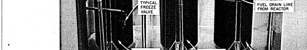
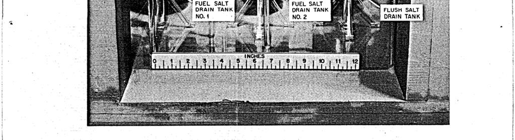
197 183 ~..,. - ARRANGEMENT i Fig Drain Tank Cell Model.
198 184 steel membrane is placed between the two layers and seal welded to the cell liner at elevation 838 1/2 ft Penetrations and Methods of Sealing Piping and wiring penetrations through the cell walls were designed to eliminate possible sources of gas leakage. All electrical leads passing through the cell walls are in magnesiafilled copper sheaths (Fig. 6.3). The sheaths were sealed to the 3/4-in. pipe penetrations by two compression-type fittings, one inside and one outside the cell. The ends of the sheaths that terminate inside the cells were sealed at the disconnect by glass-to-metal welds. The ends that terminate outside were sealed by standard mineral-insulated cable-end seals, such as those manufactured by the General Cable Company. (The seal was formed by compressing a plastic insulating material around the wires. ) All thermocouples have Fiberglas-insulated leads in multiconductor sheathed cables. The sheaths were sealed to the 3/4-in. pipe penetrations inside and outside the cell by using soft solder. The ends of the sheaths terminating inside the cells were sealed at the disconnect with glass-to-metal welds. The ends cf the cables outside the cells terminate in epoxy-sealed headers. The headers can be pressurized to test for leaks. All instrument pneumtic signal lines and instrument air lines are sealed to the 3/4-in. pipe penetrations by two compression type fittings, one inside and one outside the cell. Each of these lines contains a block valve located near the cell wall; the valves close automatically if the cell pressure becomes greater than atmospheric. Methods of sealing certain lines require special mention, as follows: 1. The 30-in.-diam cell ventilation duct contains two 30-in. motoroperated butterfly valves in series. These valves are under strict administrative contrcl to assure that they remain closed during reactor operation. 2. The component cooling system blowers are sealed in containment tanks to guard against loss of gas at the shaft seals.
199 TtiKEAOED PPE C3J PL N G C'MPRES.?ON GLAN CCMPKE5510N NUT PEN ETPATlO N SLEEVE / 1. s FTTNGS TYFCAL - * = - M U LT - CON DU CTO P. - P u lil NEPAL- hsulatet 03 COPPES-EP CATt EZ ELECTRC CABLF Q Fig Typical Electric Lead Penetration of Reactor Cell Wall.
200 The cell evacuation line contains a block valve, HCV565, which automatically closes in the event radioactivity is detected in the line by the radiation monitor. 4. check valves. 5. The air supply lines for the cell sumps contain soft-seated Jet discharge lines from the sumps each contain two block valves in series that automatically close if the cell pressure becomes greater than atmospheric. test them fcr leak tightness. A 1/2-in. connecticn is provided between the valves to 6. The fie1 sampling and enriching system is interlocked to prevent a direct opening to the atmosphere. 7. The steam-condensing system used in conjunction with the drain tank heat-removal system is a closed loop, except for the water supply lines, which contain soft-seated check valves, and the vent, which relieves tc the cell vapcr-condensing system (see see. 6.2). 8. All cooling mter lines entering the cell have soft-seated check valves or blcck valves eontrolled by ndiation monitors. All lines leaving the cells xre provided with blcck valves controlled by radiation monitors. 9. The lubricating-oil system for the fuel circulating pump is a closed circulatir-g lccp. Strict su?er.visicn is provided during additions of cil or oil sampling tc sssure that :he ccntainment is not violated. 10. The leak-detector system tubing operates at a higher pressure than the reactor prccess systems, s: nc cutleakage is anticipated. 11. Several differenti21 pressure cells and pressure transmitters zre located cutside the cells but are connected to process piping inside thrsugh instrument tubing. The instrument lines are doubly contained. The case of the differential pressure cell provides primary containment. The instrument cases are located inside a chamber designed for an internal pressure of 50 psig to provide the secondary containment. 12. All helium supply lines ccnnected to process equipment inside the cells contain one or more soft-seeted check valves. 13. Offgas lines that carry gaseous fission products to the charcoal beds are doubly ccntained for their ectire length. The offgas lines from the charcoal beds have a csmon block valve, which closes on detection of
201 L radioactivity in the line. (For details, see Dwg. D-AA-A-40883, Appendix B- 1 The stresses which exist at various penetrations in the containment vessel wall were studied and were found to be within allowable values, with the maximum stresses occurring in the nozzles Leak Testing After construction of the reactor and drain tar& cells was completed, leak tests were performed after the cells had been hydrostatically tested to 48 psig. me cells wez-e held at 20 psig for 20 hr, and a leakage rate of 0.25$/day was measured. Wken the reactor is operating, the cells will be kept at 12.7 psia, and the rate of inleakage will be monitored continuously. Mter each maintenance period, the cell leakage rate will be measured and determined to be less than l$/day (assumed in dispersion calculations, sec ) befo3.e the reactor is started. The many service penetrations carrying air, water, etc., into the cells are equipped with various closing devices, as described above. The cell leakage test does not, of course, test these devices. t is intended that such closures be tested at intervals not greater than 6 months as verification of their integrity. 6.2 Vapcr-Coridens ing Syet em W The MSRE vapor-condensing system is similar in principle to those of the SM-lA plant at Fort Greeley, Alaska, and the Humbolt Bay power plant. n the event of the maximum credible accident, vapor will be discharged from the reactor cell into tanks, where the steam will be condensed in water and the noncondensable gases will be retained. The MSRE system differs from the SM-1A and Humbolt By systems in important details, however, because the energy release rates are low and the system is adapted to an existing containment vessel. Design of the vapor-condensing system is based on the following: 39 ' 1. The volumes of the reactor and drain tank cells are, respectively, 11,300 and 6,700 ft3. These cells will operate at -2 psig and 150 F. Calculations have shown that only 7000 ft3 of noncondensable
202 188 gas will be discharged to a vapor-condensing system during the maximum credible accident. The free volume of the system was therefore specified as 4500 ft3, which is enough to contain 10,000 ft3 of gas from the reactor cell at 30 psig and 140 F or 13,500 ft3 at 40 psig and 140 F. 2. The vapor-condensing system will contain 1200 ft3 of water at 70 F or less. The full 5 x lo6 Btu calculated to be released by the salt can be abscrbed in the water without exceeding 140 F. 3. By the time the reactcr cell pressure can reach 40 psig, the steam generation rate will be 16 lb/sec or less. The rate will decrease as the rate cf release of salt into the cell decreases. The relief line from the reector cell to the vapor-condensing tank was specified to pass 16 lb/sec of steam at 40 psig with a pressure drop of 10 psi or less. The discharge end of the line is tc be located 6 ft below the surface of the water in the tank to ensure ccmplete condensation of the steam. 4. t is desirzble to keep the vzpor-condensing system isolated from the reactor cell and to limit its use to accidents in which the pressure rises nbove 15 psig. Bursting disks are to be installed in the relief line t, the vzpcr-ciridenslng tnnk. The disks will burst at about 20-psi pressure difference. Rupture of the disk in the second (smaller) line will not affect the pressure at which the other disk breaks.5 5. Vxuwr-relief xllires ~ L l be l installed in the reactor cell relief line at the vspcr-emdensing t-nk. This will permit vapors to return to the resctor cell and prevenz the pressure in that cell from going below -5 psig when the ste:tm esr,derses at the end of the accident. 6. The?rclpx-condensing system my contain as much as 400,000 curies of gasecus fission prcdacts and d2ughter prducts 5 min after the beginning Lf a maximm credible accident z d 40,000 curies after 1 hr. n addition, 1 2L. F. Pzrsly, 'blsre Containment Vessel Stress Studies, t ORNL internal document 14SX-62-15, Feb. 2, ~.. B. Briggs, "MSRE Pressure-suppression System, ORNL internal document MSR , Nov. 15, 'L. F. Parsly, "Design of Pressure-Suppression System for the MSRE," OFXL internal correspondence to R. B. Briggs, Oct. 17, Letter from T. E. Northup to R. G. Affel, May 28, 1964, Subject: MSRE Vapor Condensing System - Parallel Rupture Discs.
203 189 L the water will contain some radioactive solids that will be transferred as entrainment in the vapor. The radiation level at 10 meters from an unshielded tank would be about 2000 rad/hr at 5 min and 200 rad/hr at 1 hr; hcwever, the tanks will be shielded sufficiently to reduce the initial radiation level to below 1-00 rad/hr. Provision has been made for the controlled discharge of the gases to the atmosphere through the filter system and stack. The vapor-condensing system will be installed about 40 ft east of Building 7503, as shown in Fig t will consist of two tanks, the vapor-condensing tank and the gas-retention tank. The vapor-condensing tank, sometimes referred to as the water tank, is a vertical cylinder that is normally maintained about two-thirds full of water through which gases forced from the reactor cell in a major accident would be bubbled to condense the steam. Tke tank contains about 1200 ft3 of water plus a ccrrosion inhibitor. The estimated maximum of 5 X lo6 Btu of heat that cculd be released from the fuel salt in the reactor and drain tank cells would raise the water temyerature to about 140 F.3 The noncondensable gases are vented to a large gas storage tank. The vertical vapor-ccndensing tank is 10 ft in outside diameter and 23 ft 4 in. high, including the flanged and dished, 1/2-in.-thick, top and bottom heads. The shell is 3/8 in. thick and constructed of SA-300 class, A-201, grade 13 firebox steel. There are stiffening rings, 1 in. thick and 3 in. high, located on the exterior about 2 ft 6 in. apart. The 12-in. gas inlet pipe in the top head extends 13 ft 8 in. into the tank to about 6 ft below the normal water level. The tank is installed with the top about 8 ft below the norm1 grade level of 850 ft and the bottom at an elevation of about 819 ft. Additional earth is mounded above the tank to provide a total of 11 to 13 ft of shielding. The gas inlet line in the interior of the tank has a pipe cross (12 x 12 X 12 X 12 in.) abaut 3 ft above the water level to which is connected two 12-in. cast-steel-body check valves. These check valves close when the gas flow is into the tank but open and act as vacuum-relief valves to prevent water from being drawn in reverse flow through the inlet line during cooldown of the cell after the accident.
204 UNCLASSFED ORNL-LR-DWG R2 40ft FROM REACTOR BLDG. SPECAL EQUPMENT R N REACTOR BLDG 2-in-DAM VENT LNE TO FLTERS AND STACK FLOOR ELE ELEV 040 ft,-long BURSTNG D RELEF LNE 0-in-DAM VENT DUCT FROM REACTOR CELL 10-ft DlAM x 23-ft BUTT E R FLY CON DENS N G ELEV 024ft Fig Vapor-Condensing System.
205 191 L The noncondensable gases leave the top of the vapor-condensing tank through the 12-in. outlet pipe and flow through the expansion joint in the line to a side nozzle on the gas-retention tank. The gas-retention tank is 10 ft in outside diameter a.nd 66 ft 3 1/2 in. long, including the two 1/2-in.-thick flanged and dished head. The shell is 3/8 in. thick and is reinforced with 1-in.-thick, 3-in.-high rings located about 4 ft 7 in. apart. The tank is fabricated of SA-300 class, SA-201, grade B, firebox steel. Gases can accumulate in this tank, initially at akrnospheric pressure, but should not exceed a pressure of 20 psig. A normally closed hand valve is provided to make possible the venting of gas to the absolute filters and the Eltack. The entire vapor condensation system is designed to meet Section V11 of the ASME Boiler and Pressure Vessel Code Coritainment Ventilation Sys tem The third containment, barrier, controlled ventilation, is provided for d l areas that surround the secondary containment harrier. These 3reas include the high-bay area above the cells, the auxiliary equipment rosms on the southeast side of the building, the coolant equipment room.m the south side, and the instrument room on the north side of the reactor cell (see Fig. 3.1). The high-bay area is lined with steel sheets sealed at the joints to limit the leakage to approximately 1000 cfm at a pressure of 0.3 in. H2O. The other rooms have concrete or steel-lined walls, and each is designed for low leakage. The doors are gasketed; all service penetrations are sealed; and internal heating and cooling are provided. The general pattern of air flow is from the less hazardous to the potentially more hazardous zones. Each zone is kept at a negative pres- sure by the ventilating fan and filter system described below. This guarantees that, when the fans are running, activity leaks will he discharged to the atmosphere after filtration. t also keeps outleakage to a minimum if the fans are off; the outleakage is first into the standard building and then to the outdoors. Y The driving force for the ventilation system is located outside the reactor building and consists of t m 20,000-cfh fans arranged in parallel
206 192 so that in case of failure cf one fan the other fan starts automatically to provide uninterrupted ventilation. 30th fans pull thrcugh a bank of CWS filters that are capable cf removing pzrticles down to at least 1 J micron in size. n a fission-product spill the noble gases are the principal activities which escape from the filters. This type of filter system is employed at other reactor installaticns at the Oak Ridge National Laboratory. The fans discharge the filtered air to a 100-ft-high stack. The ventilaticn system is designed fcr several purposes: 1. During normal cperzticr, when the reactor and drain tank cells are sealed off, the ventilation system exhausts air from the building at a rate of 18,000 cfm and maintains a slight negative pressure (4.1 in. HzO) on the limited leakage zones outside the containment vessel. 2. During an accident in which fissicn gases leak from the containment vessel intc the high bay, the building inlet supply is stopped and the ventilation fam exhaust znly the building inleakage, estimated to be abmt 1000 cfn; et C.3 in. HzO. 3. During mirtenante when the contairxnent cells are opened, the vectilation system maintsins c2n air flcw of approximately 100 ftlmin through the opening (in the cmtairment cells) through which maintenance wcrk is perfcrmed. This 100-fpm f1os.r of air is intended to prevent the transfer of fission-product gases snd radioactive particles from inside the ccntainment vessel cut into the working area of the building. 4. During norm1 zperation the ventilation system serves to dilute the small quantity of fissicil-product gxes which are removed from the reactcr charcoal beds. Since the stxk flow is 20,000 cfm, and only a few cubic centimeters of fissicn g2s are discarded each day, the dilution factor is approximately loll. The stack, as it discharges into the atmosphere, provides ancther f-ctzr of 100 to 1000 dilution, depending on the weather conditicns at the time. The containment ventilation system utilizes either of two 20,000-cfkn (nominal capacity) centrifugal fans located at the base of the 100-ft-high discharge stack to induce air flow through the various containment areas in and adjacent tc Building The estimated rates of air removal from - these areas during normal resctor operation are shown in Table 6.1.
207 193 Table 6.1. Estimated Containment Ventilation System Air Flow Rates During Normal Reactor Operation Air Flow fiate ( c fm) Through Through Leaving Through Leaving Through Through Through Through Through Leaving Leaving Leaving Leaving Through Leaving Leaving supply air filter house change room high-bay at sampler enricher liquid wrzste cell liquid mste tank remote-maintenance pump cell decontamination c e 11 equipmen-l storage cell fuel-proces s ing cell spare ce:ll electrical service areas" reactor and drain tank cellsb coolant cell special equipment room vent house charcoal beds cell service tunnel 14,000-17,000 75C-1,OOO 12,000-15, , ,500 2OC ETOc-1,200 20Cb a Electrical service area includes transmitter room, north service area, and south service area (which includes west tunnel). bduring maintenance periods the air leaves the high bay through the open cell at a rate of 12,000 to 15,000 cfm. The bulk of the air, 14,000 to 17,000 cfm, enters the main building at the northwest corner through an intake air filter house. n addition to dust filters, this house contains steam heated coils for warming the intake air during the winter months. A bypass damper in the house wall assures an air supply even though the filters become excessively clogged. Another counter-balanced bypass damper prevents the negative pressure in the high-bay area from becoming low enough to collapse the sheet metal liner. Air from the intake filter house enters the high-bay area at the northwest corner of the bay through an opening about 22 ft above the operating floor level. About; 1000 cfm of air is also drawn into the
208 194 high-bay area through the change (or locker) room located at the same level. Exhaust ducts leading to the min intake ducts for the stack fans withdraw air from each of the six small cells located beneath the operating floor level* and cause air to be drawn from the high-bay area down through the openings between the concrete roof blocks covering these cells. The ventilation rates for the cells vary from 200 to 1500 cfm. Another exhaust duct pulls 400 to 600 cfm of air from the electric service area transmitter room, west tunnel, etc.; the air reaches these rooms from the high-bay area through various stairways, passages, etc. The bulk of the air frcm the high-bay area, 12,000 to 15,000 cfm, is normally exhausted at the operating floor level through two openings that flank the sampler-enricher station area. Air is drawn from the coclant cell by the same induced circulating system, and it is exhausted frsm the cell through an opening in the south wall at about the $61-ft elemtior,. Ais also enters the coolant cell through general leakage, etc., frcm cutside the building and is only partially drawn from the high-bay -2rez. During maintenance operatixs ir, the reactor or drain tank cells, air can be exhausted frx the cells to cause downflow of air through the openings xhere concrete roof plugs hcve been removed. This positive dsmward movement cr" 100 fpm, cr mcre, aids ir, preventing escape of airbcrne contaninants into cccupied building ueas. To accomplish this circulzticn, air is wi;hdraw-, -t zp ts 15,000 cfm flow rates, through a 3@-in.-diam opening at the bottom of the scuthwestern sector of the containment vessel. The alr then flows thrcugh a 30-in.-diam carbon steel duct across the ccclant drain cell and thrcugh the special equipment room to a valve pit cxtairiing two 30-in. -diam, motor-operated butterfly valves in series. The valves are ncrmally closed during reactor operation and are opened only when roof plugs &re removed for maintenance and cell ventilation is required. (A 12-in., sched-40 pipe takes off from the 30-in.-diam duct just upstream of the butterfly valves and leads to the "Liquid waste cell, remote-maintenance pump cell, decontamination cell, equipment storage cell, fuel-processing cell, and the spare cell.
209 195 L vapor-condensing system described in Section 6.2. ) The 30-in. -diam duct continues underground to the vicinity of the filter pit, where it turns upward to join the main 3G-in.-diam duct leading to the pit. The two motor-driven stack fans and the 100-ft steel stack for dis- charge of the air are located about 110 ft south of Building (Offgas from the charcoal adsorber beds is also vented through the filter pit and stack.) The containment ventilation system is provided with numerous manually positioned dampers to adjust the air flow. Differential pressure cells indicate direction of air flow, filter resistances, etc.
210 DAMAGE TO PRMARY CONTANMENT SYSTEM 7 1 Nuclear ncidents There are several conceivable incidents in which nuclear heating could produce undesirably high temperatures and pressures inside the primary system. Some of these incidents are such as might occur in any power reactor, while others are peculiar to the %RE. n the former category are uncontrolled rod withdrawal* and "cold-coolant" accidents that cause excursions by reactivity increases larger or faster than those normally encountered. Also conceivable are "loss-of -flow" and "loss -of -coolant ' accidents in which the temperature increases because the heat removal is drastically reduced. Conceivable incidents associated with particular features of the MSRE involve either premature criticality while the core is being filled with fuel salt or increases in the amount of uranium in the core during operation. Each of these could occur in more than one way General Considerations in Reactivity ncidents The severity of the power, temperature, and pressure transients associated with a reactivity incident depends upon the amount of excess reactivity involved, the rate at which it is added, the initial power level, the effectiveness of the inherent shutdown mechanisms, and the efficacy of the reactor safety system. All these factors depend to some extent on the fuel composition, because,, as shown in Table 7.1, the composition determines the magnitude of the various reactivity coefficients, the prompt neutron lifetime, and the control rod worth. n general, equivalent physical situations lead to larger amounts of reactivity and greater rates of addition with fuel B than with either A or C. This is a consequence of the larger values of the reactivity *This accident is commonly called "the startup accident" because it could occur while the reactor is being taken to criticality, This terminology is not used in the MSRE analysis to avoid confusion with the filling accident, which could occur at an earlier stage of a plant startup. v
211 197 b0 Table 7.1. Nuclear C!haracteristics of MSRF: with Various Fuels Temperature: 1200 F Graphite density: 1.86 g/cm3 Fuel A Fuel B Fuel C Uranium concentration, mo1.e $ Clean, noncirculat ing ~ Total U Operat inga ~ Total U Uranium inventory, b kg nitial criticality ~ Total U Opera t i ng a u235 Total U Reactivity coefficients Fuel temperature, "F-~ Graphite temperature, ":F" Uranium concentration Fuel-salt density Graphite density '; x x io x Prompt-neutron lifetime, sec Control rod worth, % 6k/k a Fuel loaded to compensate for 4% 6k/k in poisons. bbased on 73 ft3 of fuel salt at 1200 F. C At initial critical concentration. ficients for variable x are of the form: cients are of form: (x/k)(dk/ax) x 10-~ -3.3 x x -3.7 x m 0.21e % x x Where units are shown, coef- (l/k)(dk/dx). Other coeffi- $ased on uranium isotopic composition of clean critical reactor. e Based on highly enriched uranium (93% U235).
212 coefficients and control rod worth, the absence of the poisoning effect of Th232 or U238, and the lower inventcry of U235 in the core. The power and temperature transients associated with a given reactivity incident increase in severity as the initial power level is reduced. The reason for this is that, when the reactor becomes critical at very low power, the power must increase through several orders of magnitude before the reactivity feedback from increasing system temperatures becomes effective. Thus, even slow reactivity additions can introduce substantial excess reactivity if the reactor power is very low when keff = 1. The power level when the reactor is just critical depends on the strength of the neutron source, the shutdown margin prior to the approach to criticality, and the rate at which reactivity is added to take the reactor through the critical point. The minimum neutron source strength to be considered is 4 x lo5 neutrons/sec, which is the rate of neutron production in the core by (a,n) reactions in the fuel salt. (Ordinarily the effective source will be much stronger, because an external antimonyberyllium source will normally scpply about 13 neutrons/sec to the core and, after the reactor kas operated at high power, fission-product gamma rays will generate up to photoneutrons per second in the core. ) The physical design of $lie bebz limits tke maimurn credible rate of reactivity addition to about k/k per second. The ratio of the nuclear power at criticality to the source strength varies only -+lo$ for reactivity addition rates between 0.i35 and 3.1 Ek/k per second and the maximum shutdown margins attainable in the EBZ. For these conditions, the power level at criticality is about 2 Mw if only the inherent (a,n) source is present; it is proportionately higher with stronger sources. The power level at criticality is also higher for lower rates of reccti-;l$y addition. The principal factor in the inherent shutdown mechanism for the GRE is the negative temperature coefficient of reactivity of the fuel salt. Since most of the fission heat is produced directly in the f uel, there is no delay between a power excursion and the action of this coefficient. The graphite moderator also has a negative temperature coefficient of reactivity, but this temperature rises slowly during a rapid power transient
213 199 because only a small fract;ion of the energy of fission is absorbed in the graphite. As a result, the action of the graphite temperature coefficient is delayed by the time required for heat transfer from the fie1 to the graphite. Since fuel salt 13 has the largest negative temperature coefficient of reactivity, a given change in reactivity produces smaller excursions with this fbel salt than with either fuel salt A or C. The MSRE safety system causes the three control rods to drop by gravity when the nuclear power reaches 15 Mw or when the reactor outlet temperature reaches 1300 F. n the analysis of reactivity incidents, conservative values were assumee! for delay time and rod acceleration, namely, 0.1 see delay time and 5 ft/sec2 acceleration. (As stated in Section 2, tests of the rod system showed that the acceleration was about 12 ft/sec2.) t was also assumed that one of the three rods failed to drop. n the sections which follow it is shown that for all credible reactivity incidents, the comklination of the inherent neutron source, the inherent kinetics of the reactor, and the action of the safety system lead to tolerable transients in temperature and pressure Uncontrolled Rod Withdrawal t can be postulated that through some combination of misoperation or control system malhnction or both, all the control rods are withdrawn simultaneously, beginning with the reactor subcritical, so that considerable excess reactivity is introduced before inherent or external shutdown mechanisms begin to take effect. This accident is most severe when criticality is achieved with all three control rods moving in unison at the position of maximum differential worth. Since this condition is within the range of combinations,df shutdown margin and rod worth for all three fuels, it was used as a basis for analyzing this accident. The maximum rates of reactivity addition by control-rod withdrawal are 0.08, 0.10, and 0.08% 6k/k per see when the system contains fuels A, B, and C, respectively. The initial transients associated with these ramps were calculated for f uels B and C, starting with the reactor just critical at watt and 1200 F. (The transients for fie1 A would be practically the same as for fuel C. )
214 2 90 The first 15 see of the transients in some of the variables are shown in Figs. 7.1 and 7.2 for i uels B and C, respectively. The curves illustrate the behavior of the power, the nuclear average temperatures of the fuel and graphite, T and T+, the temperature of the fuel leaving the f g hottest channel, and the highest fuel temperature in the core, (To Max Although the rate of reactivity addition is smaller for fuel C than for fuel B, the excursions zre more severe for fuel C because of the smaller fuel temperature coefficient of reactivity and the shorter prompt neutron lifetime associated with this mixture. The power excursion occurred somewhat later with fuel C because of the greater time required to reach prompt criticality at the lower ramp rate. Peak core pressure rises were lg and 21 psi for fuels B and C, respectively. During steady-state operation the maximum fuel temperature occurs at the outlet of the hottest channel. However, during severe power excursions that are short colnpared with the transit time of fuel through the core, the xaxirnux fuel tenperahre at a given time may be at a lower elevation in the hottest chsnnel >;here the power density is relatively higher. This is illlistrated by the difference between the maximum fie1 texperature and the hot channel outlet temperature during and immediately after the initial power excursion. These two temperatures converge as the fuel is sxept from the region of maximum power density toward the core outlet while the power is relatively steady. The rise in the mixedmean temperature of the fuel leaving the core is about one-half that shown for the hottest Fuel cliam-el. The transient calculations were stopped before the fuel that was affected by the initial power excursion had traversed the external loop and returned to the core. The trends shown in Figs. 7.1 and 7.2 would continue until the core inlet temperature began to rise, about 16 see after the initial excursion in the outlet temperature. At that time, the power and the outlet temperatures would begin to decrease; the nuclear average temperatures would continue to rise as long as rod withdrawal was continued. However, the rise in graphite temperature resulting from heat transfer from the fuel would reduce the rate of rise of the fuel nuclear average temperature. v

215 2 01 Unclassified Om-DWG Time (see) Fig Power and Temperature Transients Produced by Uncontrolled v Rod Withdrawal in Reactor Operating with Fuel B.
216 202 Unclassified 0RNL-DWG c 430 h B v Tim (sec) Fig Power and Temperature Transients Produced by Uncontrolled Rod Withdrawal in Reactor Operating with Fuel C.
217 203 L t is clear from Figs. 7.1 and 7.2 that intolerably high fuel temperatures would be reached in this accident if complete withdrawal of the control rods were possible. This is prevented by the safety system, which disengages the clutches on all three rod drives when the power reaches 15 Mw and allows the rods to fall into the core. The adequacy of the high-power safety action was examined by calculations for fuel C. The transients described in Fig. 7.2 were allowed to develop until the power reached 15 Mw. The period at this time was 98 msec. At that point i-t was assumed that two rods were dropped (beginning 0.1 see after the flux reached 15 Mw, with an acceleration of only 5 ft/sec2), while the third rod continued to withdraw. The power and temperature excursions for this case are shown in Fig The pressure excursion amounted to orly 8 psi. t is evident that dropping two control rods in this accident limited the initial excursions to tolerable proportions. The reactor cannot be made critical by the withdrawal of only one control rod. Therefore the safety action is adequate for the postulated accident, and failure of the rod-drop mechanism on one rod does not impair the safety "Cold-Slug" Accident W The "cold-slug" accident is one in which the mean temperature of the core decreases rapidly because of the injection of fuel at an abnormally low temperature. The reactivity increases in this case because of the fuel's negative temperatre coefficient of reactivity. The design of the MSHE fuel system, with the core at the lowest point of the circulating loop, is conducive to thermal convection, so it is unlikely that the temperature of the fuel outside the core can be reduced much below that in the core. Furthermore, if the fuel pump stops, control system interlocks automatically prevent the pump from being restarted unless the control rods are inserted. The shutdown margin of the rods is enough so that the reactor cannot be made critical by any cold slug. (With the rods in, and the graphite at 1200"F, the critical temperature of the fuel is below the freezing point. ) Although the occurrence of a cold slug accident is highly improbable, the consequences of such an accident were calculated. n the calculations
218 TDB (see) Fig Effect of Dropping Two Control Rods at 15 Mw During Uncontrolled Rod Withdrawal in Reactor Operating with Fuel C.
219 205 L it was assumed that one core volume of fuel salt at 900 F entered the core at 1200 gpm with the core operating at 1200 F and 1 kw. No corrective action was assumed. Calculations for fuels B and C gave pressure excursions of about 6 psi in either case. Power and temperature excursions were larger for fuel B and are shown in Fig. 7.4, The progress of the transients showed that as the front of the cooler salt entered the core, the inlet temperature dropped to 900 F. As the volume of the core occupied by the cold slug became larger, the fuel's nuclear average temperature decreased slowly and added reactivity. When the reactivity approached prompt critical, the power rose sharply (on a 110-msec period) and substantial nuclear heating occurred. This caused the fuel's nuclear average temperature to rise sharply and limit the power excursion. The outlet temperature rose at first, reflecting the increased heat generation, and then, as the leading edge of the cold slug reached the top of the core, it dropped sharply. Simultaneously, the reactor inlet salt temperature returned to 1200'F as the available amount of cold fluid was exhausted. The channel outlet temperature passed through a maximum upon arrival of the fluid heated at the center of the core by the initial power transient and then decreased until, finally, the rise in the salt's inlet temperature was again reflected (about 9.4 see later) as a rise in the channel outlet temperature Filling Accidents L n any shutdown during which the reactor must be cooled, the fuel is drained from the core. Refilling the core with fuel salt is therefore a routine operation, t is conceivable that criticality could be attained before the core was full and that damaging temperatures might be produced in the partially filled core. This could occur in several ways if no safety system were available for protection. n a noma1 startup, the reactor and the fuel salt in the drain tank are heated to near the operating temperature before the salt is transferred by gas pressure into the core. The control rods are positioned so that the reactor remains subcritical after the salt fills the core. They are not fully inserted, however, so that they may be dropped if criticality
220 UNCLASSFED ORNl DWG o o 25.0 TME (see) Fig Power and Temperature Transients Following njection of Fuel B at 900 F into Core at 1200 F; No Corrective Action Taken.
221 207 is unexpectedly attained during a fill. Criticality could be reached prematurely while the core is being filled if: (1) the control rods were withdrawn too far, (2) the core temperature were abnormally low, or (3) the fuel were abnormally concentrated in uranium. nterlocks and procedures are designed for effective prevention of premature criticality for any of these reasons. The consequences were examined, however, to determine the adequacy of the safety system for preventing damage should such an accident occur. The amount of reactivity available in a filling accident and the rate of addition depend on the conditions causing the accident, the characteristics of the fuel salt, and the rate of filling. The filling rate is physically limited by the gas-addition system, which contains a rupture disk to limit the supply pressure and a permanently installed restrictor that controls the gas flow rate into the drain tank. n the case of filling the reactor with the control rods fully withdrawn, the excess reactivity is limited to the amount in the narmal fuel loading. Only about 3% 6k/k will be required for normal operation (see see. L3), and the amount of uranium in the fuel will be restricted by administrative control to provide no more than required. Filling at the noma1 rate (about 0.5 ft3/sec) with all rods fully withdrawn results in a reactivity ramp of 0.010$ 6k/k per see when k = 1. n filling the core at an abnormally low temperature, excess reactivity is added by means of the negative temperature coefficient of the fuel. For fuel B (the mixture with the largest negative temperature coefficient of reactivity), filling the core with salt at the liquidus temperature (840 F) produces a reactivity addition rate at k = 1 of only O.OOG%/sec. The greatest excess reactivity and the highest rates of addition could be encountered if the core were filled with fuel abnormally concentrated in uranium. Selective freezing of the fuel salt is a mechanism whereby an abnormally high concentration of uranium could be produced. The crystallization paths of the fuel salt mixtures are such that under equilibrium conditions, a fraction of the salt can be solidified before uranium (or thorium) appears in the solid phase. By such selective freezing the uranium concentration can be increased by a factor of 3. This phenomenon can
222 208 only be produced by extremely slo..:. cooling; normal freezing does not result in any separation. t is very unlikely that the salt in the drain tanks would be cooled slowly enough to produce uranium separation. t is even more unlikely that the concentrated liquid would be transferred to the core, since the solid phase xould remelt if the salt were heated to the normal fill temperature, Nevertheless, the consequences of a severe case of selective freezing were examined. The reactor vessel is the first part of the fuel loop to be filled, and only 61% of the salt inventory is required to raise the level to the top of the graphite in the core. Therefore it was assumed that all the uranium was concentrated in this amount of salt. (t was assumed that the solid was composed entirely of 6LiF.BeF2.ZrFk.) f the core could be filled with this concentrated salt at 12C)OCF, the excess reactivity would be about 4% 6k/k for fiels A and C end 15s 6k/k for fuel B. (The difference is caused by the aijsence in %el B 0: thorium or much U238, which act as pison in the concentrates of fuels A and C.) The reactivity addition rate at k = 1 also is muck the highest for fuel B: 0.025% 6k/k per see compared with 3.01$/sec for fuels A- md C. The rates of reactivity increese through criticality are high enough that a considerable power excursion will result and cause the safety system to drop the rods at 15 Mw. n the severe filling accident which has 5een postulated, the excess reactivity available is greater than the shutdoh% capacity of the control rods. Therefore it is necessary to stop the filling to prevent the reactor from going critical again after the rods are dropped. This is done by manipulation of valves in the reactor gas system. A simplified flowsheet of the reactor fill, drain, and vent systems, showing only those features that pertain directly to the filling accident, is presented in Fig All valves are shown in the normal positions for pressurizing fuel drain tank No. 1 to force fuel up into the core. Three independent actions are available to stop the addition of fuel to the primary loop: 1. Opening HCV-54.4 equalizes the loop and drain tank pressures. V
223 209 UNCLASSFED ORNL-DWG TO FLTER, FAN,AND STACK AUXLARY CHARCOAL BED HELUM SUPPLY Fig S,ystem S;ystem Used in Filling Fuel Loop. 2. Opening HCV-573 relieves the pressure in the drain tank by venting gas through the auxiliary charcoal bed to the stack. 3. Closing HCV-572 stops the addition of helium to the drain tank. During a filling acc:ident all three actions would be initiated automatically (at 15 Mw) to ensure stopping the fill. Either of the first two actions stops the fill almost immediately and also allows the fuel in the primary loop to run back to the drain tank. f the only action is to stop the gas addition, the fuel does not drain back to the tank, and the level r'coasts" up for some distance after the gas is shut off. This "coastup" is a consequence of the pressure drops in the fill line and the offgas line during filling. Because of this, when gas addition is stopped, the fuel level in the primary loop continues to rise until the dynamic head
224 210 losses have been replaced by an increase in the static head difference between loop and drain tank. n the case of a filling accident, the inherent shutdown mechanism for power excursions is less effective than normally because the temperature coefficient of reactivity of the fuel in the partially filled core is substantially less than that in the full system. This is so because, in the fill system, the size of the core remains constant, and expansion causes some fuel to be expelled. n the partially full core, on the other hand, fuel expansion increases the effective height of the core, tending to offset the decrease in reactivity due to increased radial neutron leakage. The effective fuel temperature coefficient of reactivity of fuel B with the core 60$ full is approximately -3.4 x 10'5/0F compared with -5.0 X 10m5/OF for the full core. The temperature coefficient of the graphite is not significantly affected by the fuel level. The most severe of the postulated filling accidents was analyzed in detail. t was assumed that the uracium ir, fuel B was concentrated to 1.6 times the normal value by selective freezing of 39% of the salt in the drain tank, and several other abnormal situations were postulated to occur during the course of the accident, as follows: 1. Only two of the three control rods dropped on request during the initial power excursion. 2. Two of the three actions available for stopping the fill failed to functioz. Only the least effectisre action, stopping the gas addition, was used in the analysis. This ol1o;:ed the fuel level to coast up and make the reactor critical after the two control rods had been dropped to check the initial poi.,-er excursion. 3. The heliun supply pressure was 50 psig, the limit imposed by the rupture disk in the supply system, rather than the normal 40 psig. This pressure gave a fill rate cf 0.5 ft3/min when criticality was achieved and produced a level coastup of 3.2 ft after gas addition was stopped. The results of calculatims of the power and temperature transients associated with the accident described above are shown in Figs. 7.6 and 7.7. Figure 7.6 shows the externally imposed reactivity transient exclusive of temperature compensation effects. The essential features are the initial, almost-linear rise sihich produced the first power excursion as

225 211 Unclassified Time (sec) 350 Fig dent. Net Reactivity Addition During Most Severe Filling Acci- fuel flowed into the core, the sharp decrease as the rods were dropped, and the final rise as the fuel coasted up to its equilibrium level. Figure 7.7 shows the power transient and some pertinent temperatures. The fuel and graphite nuclear average temperatures are the quantities which ultimately compensated for the excess reactivity introduced by the fuel coastup.
226 212 Unclassified ORNL-DWG Time (see) Fie;. 7. i. Power and Tenipera;-Jse Transients Following Most Severe F-illing Accident.
227 2 13 The maximum fuel temperature refers to the temperature at the center of the hottest portion of the hottest fuel channel. The power at initial criticality was assumed to be 1 watt. The initial power excursion was limited to 24 Mw by the d::opping control rods, which were tripped at 15 Mw. This excursion is not particularly important, since it did not result in much of a fuel temperature rise. After the initial excursion, the power dropped to about 10 kw, and some of the heat that had been produced in the fuel was transferred to the graphite. The resultant increase in the graphite nuclear average temperature helped to limit the severity of the second power excursion. Reactivity was added slowly enough by the fuel coastup that the rising graphite temperature was able to limit the second power excursion to only 2.5 Mw. The maximum temperature attained, 1354"F, is well within the range that can be tolerated Fuel Additions Small amounts of uranium will be added to the circulating fuel during operation to compensate for U235 burnup and the buildup of long-lived poisons. The design of the fuel-addition system is such that only a limited amount of uranium can be added in any one batch, and it is added in such a way that it mixes gradually into the stream circulating through the core. These limitations ensure that the reactivity transients caused by a normal fuel addition are inconsequential. Fuel is added during operation through the sampling and enriching mechanism. Frozen salt ($138 LiF-27% UF4) in a perforated container holding at most 120 g of U235 is lowered into the pump bowl where it melts into the 2.7 ft' of salt in the bowl. The 65-gpm bypass stream through the pump bowl gradually introduces the added uranium into the main circulating stream. The net increase of reactivity, once the 120 g of U235 is uniformly dispersed in the 70.5 ft3 of salt in the fuel loop, is 0.07$ 6k/k for fuel B and 0.03% hk/k for fuels A or C. This increase is automatically compensated for by the servo-driven control rod. An upper limit on the reactivity transient caused by a fuel addition was estimated by postulating that all 120 g of U235 was instantly dispersed throughout the pump bowl, from where it was mixed into the circulating
228 2 14 stream. This produce6 E step increase in the fuel concentration leaving the pump, and ;;hen this fuel began filling the core there was a reactivity increase. The largest reactivity increase would occur in the case of fuel B. (Reactivity effects ;:auld be less by a factor of 2 for fuels A and C because of their higher uraniurr corcentrations and smaller concentration coefficients oi' reactivity. me maximum rate of reactivity increase for fuel B was only 0.01'7$ Ek/k per see, which is slower than the rate at which the regulating rod moves. Therefore, wit?? the reactor under servo control, there would be no disturbance in power or temperature. f there were no rod action the rnaxinnim reacti-rity increase would be 0.09% 6k/k, during the first passage of the nore concentrated fuel through the core. Only moderate transients in pover or texperature could be produced by this much excess reactivity UOz Precipitation The chemical stability of the fzel poses safety problems in a fluid fuel reactor; for if Theses which are unusually concentrated in uranium can appear, deposits may collect 2nd cause local overheating or, if they shift position, reactivity excursions. The only known way in whic3 urani-m could become concentrated i: the XS?.E fuel-circulating system is by gross contezination of the salt with oxygen, with consequent precipitation of UO2. As discussed in Seetior;. 1.1, the fuel salt for the?ere is protected ageinst oxidation and subsequent precipitation of uranium by the inclusion of ZrF4 in the fuel selt. The ratio of ZrF4 to UF4 in the fuel will be over 5, ar:d mcre than 3 ft3 of water or 9000 ft3 of air would have to react with the 70 ft3 of fuel salt before so much of the ZrF4 was converted to oxide that 302 would begin to appear. The only my $Let such quantities of water or air could enter the system in a short period of time would be some failure or accident dlzlng maintenance with the system open. During operation, only gradual contaminatioe is at all credible. After any maintenance period and at frequent intervals during operation, fuel salt samples will be examined and analyzed fcr zirconium and other oxides. Thus oxide contamination should be detected long before the uranium began to precipitate, and appropriate action could be taken to prevent such precipitation.
229 215. L Although it is extremely unlikely that the precautions against oxygen contamination, the protection of the ZrF4, and the surveillance of samples will fail to prevent U02 precipitation, the consequences of such precipitation were considered. The most likely regions for precipitated U02 to collect are in the heads of the reactor vessel, where velocities are lowest. Collection in the lower head would create the greatest potential for a large, positive reactivity disturbance because the lower head is near the inlet to the core. There is no known way in which a substantial amount of deposited U02 could be quickly resuspended, either by physical disturbance or dissolution in the fuel salt. Nevertheless, if some UO;! were resuspended in the salt below the core, it could pass rapidly through the center of the core and muse a reactivity excursion. The greatest effect would result if it passed up through the high-velocity (2 ft/sec) channels around the center of the core. Excess uranium introduced at the lower end of a central channel would cause the reactivity to increase to a peak in about 1.5 sec and then decrease over a like period,. Calculations were made using the reactivity coefficients and neutron :Lifetime of fuel C to determine the consequences of such excursions. The temperature and pressure transients caused by this type of reactivity excursion with peaks up to 0.7% 6k/k are tolerable without any control rod action.* Rod drop at a power level of 15 Mw does not raise the tolerable reactivity addition very much in excursions of this kind, because the period at 15 Mw is so short (about 80 msec) that self-shutdown occurs before the rods have time to contribute very much. Calculations for fuel C indicated that the 15-Mw rod drop raised the tolerable reactivity peak from 0.7% to about 0.9% 6k/k. Rather large amounts of excess uranium would be required to produce the limiting excursions. Assuming that all the uranium passed through a central channel in a single blob, over 700 g of U (0.8 kg of U02) would be required to give a peak of 0.7% 8k/k when the fuel is of composition C. *Tolerable here means that the pressure excursion is less than 50 psig and the peak temperature is less than 1800 F for the most unfavorable initial power.
230 216 Equivalent excursions would be produced by about 200 g of U in fuel A or 100 g of U in fuel B. The question arises: how do these quantities compare with the amount of U02 whose separation could be detected by its effect on reactivity? A reactivity effect would be produced if the average nuclear importance of the separated uranium differed from that of the circulating uranium. The low-velocity regions where precipitated U02 may collect are at lower-thanaverage importance, so the reactivity would probably decrease if U02 were lost. During critical operation a reactivity balance will normally be made at 5-min intervals. (The on-line digital computer connected to the MSRE is programed to do this automatically, but operation of the computer is not regarded as a necessary condition for nuclear operation. ) n this balance, the calculated effects of temperature, power, xenon, burnup, and control rod positions are included. The minimum change in reactivity, occurring over a period of a few hours, that could be recognized as an anomaly is expected to be about k/k. The reactivity change caused by deposition of U02 where it contributes nothing to the chain reaction in the core is 0.23, 0.45, or 0.966$ &k/k per kg of U02 for fiels A, B, or C, respectively. Therefore the minimum amounts of U02 separation which could be detected by this means are about G.4, 3.2, and 1.5 kg of U02 for fuels A, B, and C, respectively. t is evident that the reactivity balance cannot be relied on to detect U02 loss below the level at which the conceivable effects of complete and sudden recovery become important. Any U02 deposits would probably be quite stable, however, so the probability of sudden resuspension of a large fraction of a deposit is very small. (n the HRE-2, where deposits could be dispersed by the movement of the loose core inlet diff'users or by steam formation, and the dispersed material was soluble, the largest "instantaneous" recovery was less than 0.1 of the existing power-dependent deposits of uranium.) Therefore it is probable that if U02 precipitation were to develop, it would produce a detectable reactivity decrease before any serious reactivity excursion would have a reasonable chance of occurring. This is only added assurance, however, for the real protection against damaging excursions is provided by the measures which prevent U02 formation in the first place.
231 217 Abnormal, localized heating would result if a U02 deposit (or other solids containing uranium) were located where the neutron flux caused fission heating in the deposit. One place where the reactor vessel would most likely be subject to such heating is the lower head. For this reason thermocouples are attached to the outside of the lower head and the differences between these temperatures and the temperature of the fuel entering the reactor vessel are monitored continuously to detect abnormal heating. This is primarily a means of detecting a deposit of uranium solids rather than a guard against overheating, since, from the standpoint of damage to the vessel, the heating in the lower head is not expected to be serious, even if fairly heavy deposits of uranium collect. The reason is that the specific heat source in the uranium-bearing solids on the lower head would not be intense (3 to 8 w per g of UO2 when the power is 10 Mw) because the neutron flux would be greatly attenuated by the salt and the NOR grid below the core. Calculated temperature differences at 10 Mw are shown in Fig (The differences are proportional to power. ) The curves are different for fuels A, B, and C because of differences in flux and uranium enrichment. Another region susceptible to local heating due to U02 deposition is the pocket between the top of the core shell and the reactor vessel, above the core shell support flange. There are passages at 10-in. intervals around the periphery of the support flange which bypass some salt from the vessel inlet for cooling and for providing some rotational flow in this region. Although the vertical component of the velocity in the pocket may not be sufficient to eliminate settling of U02, the swirling motion should result in art even distribution if deposition should occur. The area for deposition is large enough (180 in.2) that the loss of uranium from the circulating salt would be detectable before a U02 deposit could become deep enough tto cause intolerable heating in this region. The maximum vessel temperature in this vicinity was calculated by assuming that enough uranium separeted to cause loss of 0.2% 6k/k in reactivity and that all this uranium accumulated as U02 on top of the core shell support flange. The calculated maximum temperature in the vessel wall was
232 218 Unclassified Om-DWG UO;! Deposit (kg/ft2 ) Fig.?.8. Effects of Deposited Uranium on Afterheat, Graphite Temperature, and Core Reactivity.
233 219 L less than 1600 F with the reactor at 10 Mw and the core inlet temperature at 1175 " F. The possibility of settling on the upper support flange was examined experimentally by examining the flange area of the full scale hydraulic mockup after it had been operated with iron filings in the circulating water, but no preferential- settling in this area was observed. n summary, this examination indicates that the consequences of uranium precipitation do not appear to be of a serious nature from the hazards standpoint Graphite Loss or Permeation f a small part of t1.e graphite in the core were replaced by an equal volume of fuel salt, the reactivity would increase. The effect would not be large, amounting to lees than 0.003% 6k/k per in.3 of graphite replaced by fuel or only k/k if the entire central stringer were replaced with fuel. The reactivity- transients caused by loss of graphite due to credible mechanisms preser.t no hazard. Minor loss of graphite from the core will occur if' chips of graphite break loose and float out of the core. The vertical graphite pieces are fastened at their lower er.ds and are secured by wire through their upper tips. Thus it is very unlikely that a piece of graphite large enough to cause a noticeable change in reactivity could float out of the core. Another mechanism whereby fuel replaces graphite in the core is the bowing of the graphite stringers, which causes the volume fraction of the fuel near the center of the core to increase. The bowing is caused by the longitudinal shrinkage of the graphite under fast neutron irradiation. The radial gradient of the neutron flux causes unequal shrinkage on opposite sides of a stringer and produces bowing that is convex in the direction of the gradient. The shrinkage is very slow, and the increase in reactivity due to unrestrained bowing has been estimated at only 0.6% 6k/k per full-power year. Graphite shrinkage also causes small increases in reactivity because the moderator density is increased and because the lateral shrinkage gradually opens the channels and allows more fuel in the core. These effects are of no concern because they cause less than 0.2% 6k/k increase per full-power year and there is no possibility of rapid changes.
234 220 A reactivity increase would also result from fuel salt permeating the pores in the graphite and thus increasing the amount of uranium in the core. There is no known way, however, in which increased permeation could cause a sudden or dangerous increase in reactivity. Tests invariably have shown that the fie1 salt does not wet the graphite and that penetration of the fuel into the graphite pores is limited by surface tension, the size of the pores, and the external pressure. variables is subject to rapid or drastic change. (see ), the measured permeability of salt in the graphite is only 0.2 vol $ at 150 psig. The pressure effect on permeation produces little reactivity effect, being less than 5 x 6k/k per psi and is therefore unimportant either as a means of externally increasing reactivity or as a feedback during transients involving pressure excursions. Neither of the first two As indicated in Table 1.5 Another means for increasing the reactivity of the core is sorption of uranium OE the graphite surface. has shown evidence for such sorption. Uone of the many out-of-pile tests However, uranium in amounts as great as 1 ng of uranium per cm2 of graphite surface has been observed in a relatively thin surface layer 311 s-recimens from capsules irradiated for 153i? hr t o fission paver densities considerably above those expected for the 4SRE. experiments in Thick copious qucntities of F2 and CF4 were evolved by radiolysis of tke frozen fuel mixture. (Such radiolytic evolution prob- 2bljr occurred several t irres ~nkg the irradiation experiment since the assemblies vere coole3 though reactor shutdoms many times during their irradiation history. ) Uranium sorption has been observed so far only on graphite from the graphite by resctions such as t is possible that the uranium was laid down on * 4UF3 + 2C -9 UC2 -- 3UF4 during sudden reheat of the capsule in which the frozen fuel had thus become deficient in F2. According to this explanation the sorbed uranium would not be expected in MSRE operation. t is possible, on the other hand, that the sorbed uraniurn is due to some unknown (and thermodynamically unlikely) effect of irradiation and fission at elevated temperatures and that it can occur under conditions of operation of the MSFE. Uranium in or on the graphite, through whatever mechanism, would increase the W
235 221 reactivity of the assembly, the graphite temperature during operation, and the quantity of afterheat in the graphite. Figure 7.9 shows each of these effects as calculated for each of the three fuel compositions previously discussed. A l l effects are considerably smaller when salt C (the first salt proposed for MSRE operation) is used, but the reactivity increase, in any case, is sufficiently large to be hazardous only if it can occur in a short time Loss of Flow nterruption of fuel circulation can produce power and temperature excursions through two mechanisms: a reduction in heat removal from the core and an increase in the effective delayed-neutron fraction. When the fuel is circulating normally, delayed-neutron precursors produced in the core are distributed throl:ghout the entire volume of circulating fuel, and nearly half decay outside the core. f the circulation is interrupted at any time, the delayed-neutron effect produces a reactivity effect of 0.3% 6k/k over a period of many seconds. (The increase in the effective delayed-neutron fraction would be slow, even if the flow could be stopped instantaneously, because of the time required for the precursor concentrations to build up to equilibrium. ) A core temperature rise of less than 50 F is enough to coqensate for the increased reactivity and, because of the nature of the reactivity increase, no hazardous power excursion is produced in any case. f the reactor is at high power when circulation is interrupted, the decreases in heat removal fromthe core and heat transfer to the coolant will cause fuel temperatures to rise and the coolant temperature to fall. The only likely cause of loss of fie1 flow is failure of the power to the fuel pump. The results of a simulated fuel pump power failure at 10 Mw, with no corrective action, are shown in Fig The coastdown in flow after the failure of the pump power was simulated by reducing the circulation rate exponentially with a time constant of 2 see until it reached the thermal-convection circulation rate determined by the temperature difference across the core. (The flow deceleration was based on pump
236 222 Unclassified >.A i) Uraniur. Deposited on Graphitx (w;/cn2) no Fig Power and Temperatures Following Fuel Pump Failure, with Corrective Action.
237 c LL 0 Y W (r 3 - a (L W a H W z c 8 3 LT 6 W TME (sec) Fig Power and. Temperatures Following Fuel Pump Power Failure. Radiator doors closed and control rods driven in after failure.
238 224 loop measurements.' The heat transfer and thermal convection were predicted from basic data. ) 'The initial increase in nuclear power was caused by the delayed-neutron effects. The decrease in heat removal from the core, coupled with the high production, caused the core outlet temperature to rise. As the fuel flow and the heat transfer in the heat exchanger fell, the continued heat extraction at the radiator caused the coolant salt temperature to decrease and reach the freezing point in less than 2 min. The behavior in simulator tests at lower power was similar, but the coolant temperature remained above the freezing point if the air flow through the radiator was such that the initial power was less than 7 Mw. The effects of a fie1 pump power failure are minimized by automatic action of the safety and control systems. At nuclear powers above 1.5 Mw, control interlocks start a rod reverse (insert rods at 0.5 in./sec) as soon as the pump begins to slow down. A rod reverse is called for in any event if the core outlet temperature reaches 1275 F. perature of 130G"F the safety system drops all rods. At an outlet tem- These actions hold down the heat generation and core temperatures. The coolant salt is kept from freezing by other ection. :Then the pump stops, an automatic "load reverse" lowers the radiator air flow to about Q.2 of the normal O-Mw rate. The safety system drops the doors to shut off the air completely if the temperature of the salt leaving the radiator reaches 900 F. These actions prevent freezing of the coolant salt in the radiator. Simulator results that illustrate the effectiveness of actions similar to those designed into the control and safety systems are given in Fig Rod insertion was simulated by a negative reactivity ramp of % 6k/k per sec beginning 1 sec after the pump power was cut. The radiator door action in the present control system was not simulated. nstead the simulated heat removal from the radiator tubes was reduced to zero over a period of 33 sec beginning 3 sec after the pump power failure. '0. W. Burke, "MSRE - Analog Computer Simulation of the System for Various Conditions, '' internal ORNL document CF , March 8, J
239 UNCLASSFED ORNL-LR-DWG C LA - 0 W a 3 - a [L W a C 3 E - [L W 3 0 a Fig Effects of Afterheat in Reactor Vessel Filled with Fuel Salt After Operation for :LO00 hr at 10 Mw Loss of Load The type of incident usually referred to as the loss-of-load accident takes the form, in the MSRE, of interruption of heat removal from the radiator while the reactor is operating at high power. The most likely way for this to occur would be for the radiator doors to drop. Failure of the cooling air blowers would cause less of a load drop because natural draft through the radiator can remove up to 3 Mw of heat. The thermal and nuclear characteristics of the MSRE are such that core temperatures do not rise excessively in any loss-of-load accident, even with no external control action. Temperature transients are mild
240 226 and there is no core pressure surge, This behavior was shown in simulator Y tests in which the heat removal from the radiator tubes was instantaneously cut off with the reactor initially at 10 Mw. The temperature coefficients of reactivity for fuel C were used and no control rod action was assumed. n these tests the core outlet temperature rose less than 40 F, over a period of about 4 min. The average temperature of the coolant salt rose 196"F, with 100 F of this rise occurring in the first 60 sec. The coolant salt volume increased by 1.0 ft3, which, if there were no gas vented from the coolant pump bowl, would cause a pressure rise of 20 psi. The pressure control system would be capable of limiting the pressure rise to less than 11 psi Afterheat "he problems associated with the decay heat from the fission products (afterheat) are quite moderate in the MSRE because of the relatively low specific power in the reactor. Thus temperatures change slowly and no rapid emergency action is required to prevent overheating. This may be illustrated by considering a hypothetical situation in which the reactor vessel remains fill of fuel, with the circulation stopped, after longterm, high-power operation. The vessel contains three-fourths of the fuel salt in the system and about three-fourths of the fission products. The total heat capacity of the fuel, the graphite, and the metal vessel is 8030 Btu/"F. The estimated heat loss from the vessel at 1200 F is about 30 kw. The effects of fission-product heating in the vessel after 1000 hr at 10 Mw are shown in Fig t appears that no serious increase in temperature will result from afterheat if the fie1 is trapped in the core. After the fuel is drained from the reactor vessel there will still be some afterheat in the core from fission products which remain in the graphite. These products are there because of diffusion of gaseous products into the graphite and because of direct production by fissions in the fuel which had soaked into the graphite. The heating rate in the drained core 1 hr after shutdown from extended operation at 10 Mw is 4.5 kw, most of which is produced by the gaseous fission products and their daughters.
241 227 Unclassified 0 E- l E- Fig Temperature Rise of Fuel in Drain Tank Beginning 15 min After Reactor Operation for 1000 hr at 10 Mw.
242 228 After 24 hr the heating rate is down to only 0.G kw, so heat losses from the graphite will probably keep the temperatures from rising significantly. But even if there were no heat loss fron the core graphite (which has a heat capacity of 3350 Btu/ F), the temperature rise would not be hazardous: 27 F in one day, 144 F in 30 days. These values were calculated by assuming that fuel occupies O.l$ of the graphite volume. For this condition, the fission products produced in situ produce only one-third or less of the total heating, so the results are not very sensitive to the exact amount of permeat ion. f the fuel were transferred to a drain tank shortly after high-power operation, the rate of temperature rise in the absence of cooling would be higher than in the core because the total heat capacity connected with the fuel would be less in the drain tank than in the core. However, the drain tanks are provided with cooling tubes designed to remove 100 kw of heat from the salt at 1200 F. This heat-removal capacity is adequate to prevent 8 significant rise in temperature. The predicted heat loss from a drain tank at 1203 is 20 h.:. Figdre 7.13 shows the expected temperature rise of the fuel charge in a drain tank beginning 15 min after the end of 1003 hr of operation at 10 Mw. (t will take approximately this long to get the salt into the drain tank. The temperature at this time will depend on the mamer of shutting down the nuclear power and the radiator heat removal, bct it vi11 be near 1200 F.) The heat removal rates of 213 and 120 kw correspond: respectively, to heat losses and the heat removal with the coolfxg system working as designed. The heat capacity of the L OR taak and structure was ignored in computing the temperature rise. As was described in Section 1.2.5, the cooling system for the drain tanks is based on the evaporation of water, but the water and salt are not in contact vith a comnon wall. The evaporation-condensation circuit is completely closed and requires no pumps because the condensate is returned by gravity. An emergency reservoir of 500 gal is installed to provide cooling for 6 to 6 hr. During this time, hoses could be connected to provide a temporary supply for an indefinite time.
243 229 Unclassified Tim (hr) Fig, Heating of Reactor Vessel Lower Head by U02 Deposits with Power Level at 10 Mw.
244 Criticality in the Drain Tanks Fuel salt having t.he uranium concentration appropriate for power operation of the reaccor cannot form a critical mass in a drain tank or in a storage tank under any conditions. Only if there were a large in- crease in uranium concentration could criticality occur in a tank. only credible way for this to occur would be for the salt to freeze gradu- ally, leave the UF4 in the remaining melt, and thereby concentrate the uranium into a fraction of the salt volume. concentration by nore than a factor of 4 would be necessary for criticality in any such case. 2 The Calculations indicate that Concentration of the uraniuk is not impossible; gram-scale studies of equilibrium cooling of fuel salt mixtures indicated that the last phase to freeze was 7LiF. G(Th,U)Fr, containing about three times the uranium conceri- tration of the origi:lnl flel drain tari, it is unlikely tkat suck gross segregation would occur. Convectisn currents within the luge mass md initial freezing on the many cooling tkimbles sho-dd keep the segregated salt distributed through the mess. HLir.resrer, in a vessel as large as the Zven so, special neascres hsve been taken to prevent freezing. leater failures are not likely to cause accidental freezing, since a teqerature af i20c'f can be mai2taine3 with only about 0.6 of the installed hzaters in cpretlon. than 2.1- hr w>u:i 'ct reqcireci for the keat.osses (about 20 kv) to cool the salt to ';he 1 i.,:pkl~.x tenperatu.re of g43"f. would extend tkis ziri-ie by mny!:ours. length o? ti?:e LE extrenely unllkely because the reactor ares is supplied by two separztc l*eedcr lines a:lc there are tlree emergency di generating uni%s in t1:e area, any of which could supply yo'y:e- to the heaters. Even if the heater?over should be cut off, more Fission-product afterheat A corrplete power failure for this ir, the event all these sowces Failed, or for my reason it shoulc become necesszry to allow the fuel salt to solidify and cool to ambient temperature, the risk oi" criticality due i,c selective freezirg -ctric 2J. R. Engel and E. E. Prince, "Criticality Factors in MSHE Fuel Storage and Drain Tanks, ' USAEC Report ORNL-TM-759 (to be published). Oak Ridge National Laboratory Status and Progress Report November 1963, p. 15, USAEC Report ORTL-3543.
245 231 will be eliminated by dividing the fuel between two tanks, neither of which will contain enough uranium for criticality. This can be done because one drain tank will be kept empty for such an emergency. Although criticality in the drain tanks is undesirable and can be avoided as described above, the consequences would not be severe. Because criticality could occur only after at least three-fourths of the salt had frozen, the initial temperatures would be moderate. When the concentrating process slowly reached the point of' criticality, the power would rise to match the heat losses without any serious power excursion. (The salt contains a strong (a,n) source; the reactivity would be increasing very slowly through the critical point, and there is a negative temperature coefficient of reactivity. ) The establishment of a self -sustaining fission chain reaction in a tank should therefore present no threat to the containment of the fuel. Furthermore, the location of the tanks and the shielding around them is svch that radiation from a critical tank would not prevent occupancy of the building and emergency work toward restoring heater power. 7.2 Nonnuclear ncidents Freeze-Valve Failure The freezing and thawing of the freeze valves could conceivably result in a rupture of the piping. This is specifically minimized in the design by making the freeze-valve section as short as possible so that there is small danger of bursting as a result of entrapment of liquid between the ends of a plug. Because the salt expands as it thaws, special precautions are taken to apply the heating so that expansion space is always available. A single freeze valve has been frozen and thawed more than 100 times without apparent damage Freeze-Flange Failure The flanged joints in the fuel-circulating loop might also fail. The freeze flange was selected as the simplest and most reliable joint available, and the strengths of the bolting and the flange compression members
246 232 are considerably in excess of those necessary to maintain a tight joint. Typical flanges have been tested by thermal cycling over a period of more than two years, and there has been no indication of unsatisfactory performance. The helium-pressurized leak-detection system will monitor constantly for leakage and will protect against leakage to the outside Excessive Wall Temperatures and Stresses Overheating of pipe and vessel walls might occur because of external electric heating or internal gamna heating. The heater elements have a melting point several hundred degrees above thzt of the NOR-8, but it is. not considered likely that the NOR-g could be melted by external heating so long as salt was present inside the pipes. f salt were not present, the pipe wall might melt before the heater element melted, but in this case only a small fraction of the activity would be released. Wall temperatures will be rneasured by kxnereds of thermocouples and will be constantly scanned to prevent excessive heating. Also during prestartup testing, the controls of all external heaters and the resistance-heated drain line will be provlded with mechanical stops set to limit the power input of each circuit to values that meet the heat input requirements with a small excess capacity. During reactor opera$i3n, various components will be exposed to high gamma fluxes that will cause garma heating of the components. f this keating produces large texperatlre gradients, excessive thermal stresses may arise. The effects of gama heating on the core vessel and the grid structure were investigated because these structures will be in regions of the highest gamma flux. The gama heating of the core vessel will result in a temperature difference of only 1.3"F ecross the vessel walls and will produce a calculated thermal stress of 300 psi, which is not serious. The temperature difference across each grid of the support grid structure will be 3.8"F, and the resulting thermal stress will be 850 psi, which is also not serious. Gamma and beta heating of the top of the fuel-pump bowl will result in a m a x i m thermal stress of about 8000 psi at the junction of the bowl u -
247 233 L with the volute support cylinder, with cooling air flowing at 200 cfm across the bowl. The junction temperature under these conditions will be about 1000 F. Considerably higher stresses will occur at cooling air flow rates other than 200 cfm during power changes. The highest stress, about 19,000 psi, will occur in changing from 0 to 10 Mw, with the cooling air flowing at 50 cfm. With a gas pressure of 5 psig in the bowl, the maximum combined circumferential and meridional pressure stress will be about 300 psi in the pump bowl and about 400 psi in the volute support cylinder at the junction. The resulting rraximum combined stress with cooling air flowing at 200 cfm will be 8400 psi, and, with air flowing at 50 cfm, 19,400 psi. n a normal thermal cycle after a complete shutdown, the temperature of the reactor will vary between 70 and 1300 F. With such a range, there are possibilities for excessive stresses as the piping expands and contracts. Particular attention has therefore been given to providing a flexible layout. Analyses of the extreme conditions have indicated that the maximum stress caused by expamsion or contraction is only 7050 psi. nstrumentation is provided to observe the normal rate of heatup or cooldown, which will not exceed 120*F/hr. Thus it does not appear reasonable that primary containment failures will occur as a result of excessive temperatures or thermal stresses Corrosion Another possible cause for failure of the primary container is corrosion. As reported in Section 1.1.2, the corrosion rates experienced with the NOR-8 alloy have been very low (less than 1 mil/yr) for periods as long as 15,000 hr. All available evidence indicates that it is extremely unlikely that corrosion will be a cause of piping failures. Numerous corrosion tests have been completed with fuel mixtures of the type to be utilized in the MSRE. Results from 37 NOR-8 thermalconvection loops, 17 of which operated in excess of one year, have shown complete compatibility between NOR-8 and the beryllium-based fluoride systems. Experiments conducted in NOR-8 forced-convection loops for one year or more similarly have shown low corrosion rates in fluoride mixtures
248 234 of this type, below: The operating conditions of these experiments are shown Forced - Thermal- Convection Convection Variable Loops Loops W Fluid-metal interface temperature Fluid temperature 1300" F 200" F 1350" F 170 " F gradient Flow rate -2 gpm 4' fpm Metallographic examinations of NOR-8 surfaces following salt exposure in these loop experiments reveal no significant corrosion effects in time periods up to 5000 hr. At times longer than 5000 hr, a thin (less than 1/2 mil) continuous surface layer develops at the salt-metal interface. Some typical weight-lsss data are presented below: Weight Loss Tine (hr) rngjcm 2 ng/cm2/mo - 5, , , Sixteen in-pile capsules exposed for 1503 to 1700 hr each4 and five in-pile fuel-circulating loops5 which ran a total of 3000 hr have been examined for evidence that corrosion under irradiation is different from that out of pile. Particular attention was paid to the possible effects of free fluorine. ;io evidence was found which indicated that high irradiation levels altered the normal corrosion pattern. t has been suggested that the high radiation levels in the controlrod thimbles and in the reactor cell might cause formation of sufficient 40ak Ridge National Laboratory, "MSRP Semiann. Frog. Rep. Jan. 31, 1963,'' USAEC Report ORTJL-3419, pp '7, and "MSRP Semiann. Frog. Rep. July 31, 1963," USAEC Report ORTCL-3523, Chapter 4. 5D. B. Trauger and J. A. Conlin, Jr., "Circulating Fused-Salt Fuel rradiation Test Loop, ' FJucl. Sei. Eng., 9(1 j : (March 1961). Y
249 23 5 L nitric acid (from the N2, 02, and H2O in the cell) to create corrosion problems. A calculation for the most pessimistic conditions indicates that the concentration of nitrogen oxides in the cell atmosphere might reach 1% in 4000 hr, the longest anticipated period of continuous operation. The actual concentration should not be this high. The HRE-2 was operated under similar conditions without observable damage from "03, so no real problem is expected. Corrosion in the MSRE will be followed continuously by means of the salt chemistry, which will indicate nickel removal. Salt samples for this purpose will be removed and analyzed daily. At approximately 6-month intervals, the surveillance specimens referred to below will be tested Material Surveillance Testing Surveillance specimens of NOR-8 and type CGB graphite will be placed in a central position of the reactor core (as shown in Fig. 1.6) to survey the effects of reactor operations on these materials from which the reactor and moderator are constructed. The specimens will be made from the material stock used to fabricate the reactor primary system and moderator. Separate but identical control specimens will be exposed to a duplicate thermal history while submerged in unirradiated fuel salt in an NOR-8 container to differentiate between the effects of temperature and the effects of irradiation. Specimens will be removed from the reactor and examined after six months of operation and then again after periods of operation that should result in meaningful data based on the results of the first set of specimens. New specimens will replace the material removed. The analysis of NOR-8 specimens will include metallographic examination for structural changes and corrosion effects, mechanical properties, and a general check for material integrity and dimensional changes. The graphite specimens analysis will include metallographic and radiographic examination for salt permeation and possible wetting effects, mechanical properties tests, dimensional checks for shrinkage effects, chemical analysis for deposits on the graphite, electrical resistivity measurements, and a general inspection for material integrity.
250 236 The results from surveillance specimens will be available in plenty of time to guide decisions on the allowable safe exposure of the graphite and NOR at various locations in the reactor. 7.3 Detection of Salt Spillage The escape of activity from the primary container would be detected by radiation monitors. f the spillage were into the secondary container, the activity would be indicated by monitors on a system which will continuously sample the cell atmosphere. Leakage into a service line (e.g., the cooling water) wolld be detected by monitors attached to the line just outside the cell. n either case, the action of the monitors would be to stop power removal and to insert the control rods. The salt would be drained unless the leak were in a drain tank, in which case it would be transferred to another tank. 7. L Nost Probable Accident Although the chances of tiny failure are extremely small, one of the bbove described noncuclear incidents can be considered as the most likely cause of leakage from the prixary containment system. Based on previous experience with fluid-fuel reactors, it is believed that the most probable type of leakage would be a slow drip or spray at a rate of a few cubic centimeters per minute. t is further believed that the leakage would be detected 2nd the reacxor shut down before more than 3 or 4 liters had escaped. By this tine, aboiit 20,333 curies would have been released into the secondxy contsiner. f 135 of the solid fission products (approximately 1439 curies), lq$ of the 12 (approximately 480 curies), and all the xenon and krypton (zpproximately 3230 curies) were dispersed in the cell atmosphere, the concentration of activity inside the container would be curies/cm3, which would alarm the cell air radiation monitors and shut down the reactor. This activity (neglecting decay, for simplicity) would be pumped from the cell by the container vacuum pumps as they maintained the cell pressure below atmospheric by compensating for the 10 6$/min W
251 237 L normal inleakage (at 13 psia). The activity would be discharged through line 917 to charcoal bed 3 and then to the absolute filter-stack system. Assuming that the carbon bed and the absolute filters are reasonably effective, the disposal of the activity would not be a large problem, and concentration could easily be kept below the MPC,. Even without the charcoal bed the concentration of iodine would probably be tolerable (see Appendix D). After an accident such as that described above, it would be necessary to open the secondary container to repair the failure, and the activity would be released at a rate considerably greater than the normal rate of cell inleakage. n this circumstance, the container inleakage would be increased manually, and the concentration of activity in the stack would be increased to levels which would permit maximum discharge without exceeding permissible exposures downwind. n any case, the container would not be opened for repairs until the activity concentration inside was low enough to prevent overexposure in case the cell ventilation system failed.
252 sidered. The possibilities flr dmzge to :?e secoiidai'y container were con- As indicated belcw, danage frm missiles is unlikely, and prc- tection is provided agaimi the -0-dildup af excessive interrial pressure. Site studies kve indicated that no pycblems exist wi:h respect to earth- quakes 2nd flsods, ard prctecticn h-s been provided against the conse- quences sf arscn. The analysis =." the mxfnm credible accidens, which in-\ml-;es simultar-ecus release cf tke nclren fuel and water into the sec- ondary container, led t- the icccrpc-a;icr of a 1-apor-condensing system fcr limiting the cprtainer press-:-:-e 43 psig. The consequences of release of radioac:i-?i:y credible acclder,t vere anal;.ze3 zcr T:;C frzm tke sec ndary cmtainer after the maximum sitzatlons : with the stack fan ciff and wl5h the sraek fen still r-miicg and passjrg -he effluent thrcugh a'cs2lute filters. All d-ses x'ere cxd i; be low enough to allow evacxa- ticr of :he bxilding Li> ayes ir, -easciiab1e 4drr.es irithout overexpcssre Szlt Spillase The spillage of the salt at E high tem?erac,lx'e does haxre possibilities Tcr raising the cell pressue ti? high values. of all the salt in bctk tle fuel snd Zocian; s:-sterns wi uld hea- the cell L'L rspid spill into the zell V
253 23 9 atmosphere sufficiently to produce a 2.4-psig final pressure.' f the fuel were released as a fine spray, the maximum pressure would be 16.4 psig. The worst situation would be the simultaneous release of the salt and the inleakage of the correct amount of water to allow the generation of steam without subsequent cooling from additional inleakage of water. This accident is considered to be the maximum credible accident and is discussed in detail in Section Oil Line Rupture The fuel-pump lubrication system contains a maximum of 28 gal of oil, which, in the event of an oil-line rupture, could come into contact with the hot pump bowl and the rea,ctor vessel. With an atmosphere containing the normal 21% of oxygen in the cell, the oil would burn and produce an excessive pressure in the cell, cr it would form an explosive mixture that might later be ignited. To ensure against containment damage by these possibilities, the oxygen content of the cell will be kept below 5% by dilution with nitro- gen. Nitrogen will be fed into the cell continuously to maintain the low oxygen content. 8.3 Acts of Nature Earthquake As reported in the site description, Section 4.3.8, earthquakes are not a problem at this site Flood The topography of the MSRE site indicates that flooding is highly unlikely. S. E. Beall, W. L. Breazeale, and B. W. Kinyon, "Molten-Salt Reactor Experiment Preliminary Hazards Report, USAEC Report ORNL CF , Oak Ridge National Laboratory, February 1961.
254 240 &.it Sabotage Severe damage to the reactor by sabotage would be difficult; arson is probably the best possibility. The consequences of fire are minimized by fireproof structures, a sprinkler system, and an alarm system that automatically transmits to the fire-protection headquarters at X-10. Water for this system is supplied to the building sprinklers by the main line from X-10 and two 1.5 million-gallon reservoirs near the site. Only a person with intimate knowledge of the reactor would be capable of inflicting damage that might result in reactor hazards. This possibility is minimized by adequate personnel policies and security regulations, particularly with respect to visitors. 9.5 Ccrrcsion from Spilled Salt an accldent invclvir-g contac: cf 17ater and fluoride salts in the ccn;airmezt vessel, fair1;- rapid generation Jf h;-drofluoric acid is ex- 7ecteC. Part of the 3 wlll-se dispersed as vapcr in the cell and part ne 4- "_ >;ill diss-lve in tale kater. Corrosion damage resul',ing from dis- soli.i.ec if is grelt117 deferden; qzra tke temperatldre a-d the concentra- --,,,,. nf per year with teqerstxe rtir-ges frorn 70 zc 330"1-' and XE concenrrations frm 1G to 1005 :;? veigk lis;-e beeii r.cpor;ed. * Sirxe the bottom hemi- s?herical section cf :'re :crtair_rrent -:esse1 is 1-in.-thick plate with a protective paint ccatirig, there is litde imediacve danger of ccrrosion- caased weaker3-g c-?f 2? CzrrosLori penetr3ki:ns tke?ell. rmging frox 3.0CS in. per year tc 0.79 in. 3':~9.six has been made for the addition neutralizirig sclutlcr- ir: case experiments indicate that the corro- sion might damage the s.essel within several months after a spill. 5.6 Tvbximm Credible Accident The maximum credible accldent for the :.SRE involves release of the molte- fuel from the reactzr vessel axl fuel-circulation system irito the Handling of Flucrine and FluoriGe Compounds with nco Nickel Alloys, The nternaticnal Nickel Co., nc., Mew York, Pi. Y.
255 241, 'W t reactor This can occur as a result of a break in the 1 1/2-in. - diam drain line or in a 5-in.-diam fuel-circulation line. The fuel circulation lines enter and leave the reactor vessel near the top; so 4000 lb or less of salt would be discharged through a severed line; this could occur in about 15 sec. All10,OOO lb of salt could be discharged through a severed drain line in about 370 sec or through a combination of severed drain and circulation lines in about 280 sec. The calculated quantity of fuel released as a function of time is shown in Fig. 8.1 for the latter two conditions. The pressure produced by the release of salt into the secondary container depends on the reactions with the environment. The oxygen content of the cell atmosphere will be kept low enough (by purging with nitrogen) to prevent fires and explasions. No significant exothermal chemical reactions can occur between the salt and the materials in the reactor cell. Any pressure rise must result from heating of the cell atmosphere and from generation of steam by contact of the salt with water. The actual pressure rise will depend on the rate of release of heat from the salt to the atmosphere and to water and on the rate of dissipation of heat from the atmosphere by space coolers and by transfer through the walls of the reactor and drain-tank cells. Because of the many uncertainties in these rates, the reactor and drain-tank cell pressures were conservatively estimated on the basis of (1) equilibration of the fuel salt with the cell atmosphere and (2) equilibration with an amount of water that would evaporate completely to form saturated steam. Equilibration of the salt with the cell atmosphere alone would result in a rise in cell pressure to about 18 psig and a gas and salt temperature near 1200 F. Because the total heat capacity of the gas is small in comparison with that of the salt, the final temperature and pressure calculated in this mnner depend only slightly on the amount of salt spilled if it is in excess of 1000 lb. Water will be used as the coolant for the cell air coolers and the pump motor, and there will be water in the reactor thermal shield. Thus 'W R. B. Briggs, "MSRE Pressure-Suppression System, ORNL internal 3 document MSR , Nov. 15, 1961.
256 242 10,000 Unclassified ORNL-LR-DWG ,000 2, ooc C Tine (sec) 400 Fig Release of Fuel Through Severed Lines.
257 ~ L there is a possibility of simultaneous spillage of water and salt into the cell. Equilibration of all the fuel salt with the cell atmosphere and just enough water to forrn the maximum amount of saturated steam would result in the maximum pressure in the secondary container. The relationship between the amount of salt equilibrated with water and the cell atmosphere and the resulting pressure is shown in Fig With no relief device, pressures as high as 110 psig could result. The vapor-condensing system described in Section 6.2 is designed with a rupture disk to relieve at 20 psig, so that after an estimated 10 sec, 12c UNCLASSFED ORNL DWG s oc 8C -.- rn 2 6C - W a 3 v) v) w E 40 J _ w RUPTURE DSK RATED AT 2Opsig c t SALT WTHOUT WATER ---t-+- O ,000 WEGHTS OF SALT AND WATER EQULBRATED (b) Fig Relationship Between Cell Pressure and Weights of Fluids Equilibrated.
258 ~~ 244 the steam would flow to the vapor-condensing tank at a rate of about 16 lb/sec. After 5 min2 this worst accident should be ended and the pressure approaching normal. The fission product afterheat would be dissipated easily to the vessel and its annulus which has a heat capacity of about 400,000 Btu/" F. Two relatively large-scale experiments4 were conducted to study some of the consequences of a salt spill. The first test was a 1/20-scale experiment with 500 lb of salt at 1500 F. The MSRE containment vessel was represented by a 10-ft-diam spherical vessel with a water-filled annulus. The test demonstrated that large amounts of heat can be transferred at relatively high fluxes (40,003 to 10@,0Oc) Btu/hr. ft2) from the pool (or cake) of salt to the steel vessel and its annulus without damage to the tank. Btu/hr. The average heat transfer rate for this experiment was 3 X lo6 The temperature of the tank bottom rose to 940 F in 75 sec and fell to less than 250'F in 6 min. n the second test, the sane qmntity of salt (500 lb) was quickly drained (50 sec) into the 10-ft-diam tank filled to a 5-ft depth with water. The salt contaixd 25 tc _"J ac of mixed fission-product activity (6 days old). Althowh the physical shock to the water and the tank were ;5olent, nothing appron-hi% 22 explosion vas observed. Only a small amount of stea?: reached the surfxe of the water. The radioactivity of the water was rneasx-e:! af",rwards ane was found to account for less than 3% of the oi-iginal acti-2ty. These relatively crude but very convincing tests indicate that the assumptions made in the maxima credible accident are reasonably conservative, that the contairment vessel should withstand the thermal shock of hot salt, and that most of the fission products remain in the salt. As mentioned in Section 6.1.1, and 8-in. vent pipe is installed to relieve the steam which might be formed uder the bottom of the MSRE containment vessel in the event of a large salt spill. 'J c 'L, A. Mann, "ART CF , Oak Ridge Reactor Accident Hazards Tests, '' USAEC Report ORNL National Laboratory, February 1955.
259 Release of Radioactivity from Secondary Container Rupture of Secondary Container t is considered incredible that any single accident (sabotage ex- cluded) could rupture both the primary ar;d secondary containment Release of Activity After 'hxinlum Credi1:le Accident As discussed abcve, the most sever'e accident considered to be cred- ible is the simultaneous spillage of salt and water into the secondary container. The release of fission products and the ccmequences of re- lease have been studied, fcllowing the general procedure outlined in P-irt 100 of the Code of Federal Regulations, Title 10, as published in the Federal Yegister. were based were the following: The speciyic assumptions cn wh cli the calculation:. 1. The secondary container pressure is vented to the vapor-condensing system at 20 psig. to atmospheric pressure as the steam condenses over a 4-hr period (see Ap- pendix E). The pressure rises to a maximum of 39 psig and decays 2. The secondary container initial outleakage is l$ per day (0.04$ per hr) at 39 psig The building outleaksge is 105 per da;; { 0.4$ per hr). The iodine release from the salt is 10% or 2.50 x lo5 curies, with a 505 plateout on the sezondary container surfaces. periment~~ in which the solubility of the fuel salt in water was mea- sured, much less iodine is expected to be released.) The noble gas release is 100% or 3.75 x lo5 curies. (Based on ex- The solid fission product released is 10% or 6.8 x lo5 curies. The methods of calculatim are given in Appendix A. considered: Two cases were one with the fan off and the other in which the stack fan continued to operate to discharge the contents of the building from the 5&th Slusher, H. F. McDuffie, and W. L. ~rshall, "Some Chemical Aspects of Molten Salt 3eactor Fafety, " U W C Report ORNL-TM-458, Oak Ridge National laboratory, Dee. 14, 1962.
260 _ ft-high stack at 15,000 ft3 mil:. passes through abso1u:e 99.9% for 0.5-p particles. i'ith <he fan running, the effluent filters, which have an assumed efficiency of Activities nside Bdlding 'he calculated dose rates with the fan rw-ing are plotted iya Fig. 2.3, which shows that the dose rate reaches a maximum of abcut 12 r/hr after 1.1 hr. the peak activity; le-,-els inside the building are approximately a factor of 5 higher. ents inside the building are shown in Fig With the stack fan off, The cxcentrs;icns cf :he various fission-product constitu- Personnel within the building cccild escape from the building high bey without receixtirlg the rnx5~m permissible doses, as indicated in Table 8.1. Appendix A gives 3etzls of the rnethcd used for these calculations. Tie escape tines are nzt -3ec;ed appreciably by the operatiorcf the fans; the niininum cl' 6.5 xir- {fer r- bone seeker dose of 25 rem) s: xcre than safp icleni tlze far e-,-:lcuatit;n fr:m any locatioe wi",hin the 5 cilding,.hxinim - Type of -rkala t Zscape T'irne 211 Fissicr, Fermi s s bl e WdUC.t Dcse Gzse?an On Fan Off iccilne 3129 renl 963 pc 40 min 33 min Scble 2; r ex+. gases a3 2.2 hr Solids 25 1'PPl 221 pc 7.0 min 6.5 m ir Dose Rates Outside Building 7503 Following the Max5rrrj.m Credible Accident. The maximum activity ic the building is calculated to be 183 curies at 1.1 hr with the fan on and 932 curies at 4 hr with the fan off (see Appendix A, Tables A.l and A.2). Figure 8.5 shows the dose rate at various distances from the building due to the ectivity in the building. The radiation level from the radioactive cloud (normal atmospheric conditions) and the total radiation level are plotted on the same graph.
261 247 Unclassified OR&-DWG L 5 2 Time After MCA (hr) Fig Radiation Level in Building Following Maximum Credible Accident (r/hr = 935 x pc/cm3 x Mev).

262 248 10' Unclassified ORNL-DWG ' +' Q 13' 10?he After MCA (hr) Fig Activity Concentrations in Building Air Following Maximum Credible Accident.
263 249 1oo.c 80.C 60.0 UNCLASS F1 ED ORNL DWG FAN OFF ---FAN ON - 40.C L f 6.0 E - J W 4.0 > w J z 0 + Q 2.0 n a LT FROM BULDNG (ALSO TOTAL, FAN ON) -?\$!!;---.O ( DSTANCE DOWNWND OF MSRE (m) Fig Noble Gas Activity After Maximum Credible Accident as Function of Distance Downwind. With the fan off, essentially all the radiation is due to the activity in the building. Beyond 450 meters from the building, which is the ap- proximate distance to the HFR, the peak radiation level is less than 2.5 mr/hr (see Appendix A for calculations ).
264 250 - Release of Activity from the Building. The release of activity from the high-bay area of the building was considered with the fan off and with the fan on and under normal and inversion atmospheric conditions. Since there is an installed spare fan and the fan can be operated from diesel power if necessary, the probability is very low that the fan would be off. Figure 8.6 shows that the activity release rate is an order of magnitude lower 7 hr after the maximum credible accident with the fan running. The meteorological conditions and method of calculation are given in Appendix A. Figure 8.7 shows the total integrated thyroid and bone dose resultiq from the maximum credible accident. t can be seen that the maximum emergency doses of 300 rem to the thyroid and 25 rem to the bone are exceeded only at distances within 300 meters downwind of the MSRF: with the fan off. With the fan running the maximum doses are less than 5 rem. The maximum off-site exposure (beyond 3000 meters) is 6 rem from iodine under inversion conditions with the fan off (see Appendix A for calculations). The peak activity concentrations are plotted in Fig. 8.8 for iodine and solids. These peak levels occur at 1.1 hr after the maximum credible accident with the fan on and 4 hr after the maximum credible accident with the fan off. The change in release rate with time is plotted in Fig t was assuned that?9.$ of the solids would be removed by the filters with the fan on, but there would be no removal of iodine. There is some evidence that iodine in large quantities would be removed by absolute filters by agglomeration 0: the very fine particles,6 but no credit was taken for this effect. n the case of the maximum credible accident coinciding with an unfavorable wind in the direction of one of the nearby sites, such as KFR (L60 meters southeast) or ORK (800 meters northeast), the possibility was considered that evacuation might be required. A quarterly dose of 8 rem to the thyroid and 1.5 rem to the bone was considered the maximum allowable dose in this case. Porn Fig. S.7 it can be seen that the doses at 6M. H. Fontana and W. E. Browning, Jr., "Effect of Particle Agglomeration on the Penetration of Filters Utilized with Double Containment Systems, ' USAEC Report ORNL-NSC-1, Oak Ridge National Laboratory, Sept. 25, 1963.
265 251 1 Unclassified ORNL-DWG 6A k d Time After Accident (hr) Time Fig Change in Rate of Activity Release from Building with
266 UNCLASSFED ORNL DWG W m 0 n n W J a 5 _ a NORMAL CONDlT/ONS AND 2 0 mrem FOR NVERSON COND~ONS io too , DSTANCE DOWNWND OF MSRE (m) O Fig Total ntegrated Doses Following Maximum Credible Accident. the above two distances do not exceed the maximum doses for continuous occupancy except with the fan off under inversion conditions. Under inversion conditions the total integrated iodine dose at 460 meters would be 13 rem. However, the dose for the first 8 hr would be only 0.75 rem (for a maximum air concentration of C.16 pc/m3), and the maximum dose would never be reached with an E-hr working day and the decreasing release rate. n the case of bone seekers for the same conditions, the first 8-hr integrated dose would approach the 1.5 rem, but unless the
267 253 UNCLASSFED (0' E O Fig Peak odine and Solids Activities after Maximum Credible Accident as Function of Distance Downwind.
268 2 54 accident occurred at the start of a work period, the dose would be less than 1.5 rem. Rainout. The hazirds sssccisted with the deposition of all the fission products in the radioacti\-e cloud due tc rainout were considered for the case of the fer cn under nornal atmospheric conditions. Ey integration of the formules for the tincunts of iodine, noble gases, and solids in the building times the release rate with respect to time, a tctal of approximately LOO curies cf -.ctivity was found to be released, essentiall:; sll is the first L 3:- fcllcwir-g the maximum credible aceiden;. The depcslticn, in cui-'ies/n2, was determined by using the formula, 7 Q The dose razes in rep,/hr, given i:i Table 3.2, were obtained by multiplying Table 3.2. Dose Rates from Rainout Distance from Building 7503 (m Maximum Deposit ion ( curies/m2 j Dose Rzte (rep/hr j odine Total 50 4 x x x 10'~ x 3.5 X , X 6 X loa ,000 1 x 4.5 x , x 8 x
269 255 'L the surface contamination in curies/m2 by 10 (ref. 8). For inversion conditions the deposition is about 30% greater because of the higher stability parameter. 8.8 Release of Bervlliim from Secondarv Container The volume of fuel salt in the primary loop is 73 ft3, and the weight of beryllium in the primary systen is 220 kg (salt A). Although it is doubtful that as much as 1% or 2.2 kg of the beryllium could be suspended in the secondary container atmosphere, even in the event of the maximum credible accident, this amount was assumed for the hazard calculation. At a 1% per day initial leak rate from the container (with a pressure of 39 psig), the beryllium concentration in the building would reach the maximum permissible concentration for workers without respiratory protection (25 pg of Be per m3) in 150 sec. This is sufficient time to put on masks and to escape from the building. From Fig. 8.9, it can be seen that the beryllium concentrations downwind of Building 7503 would be considerably less than 2.5 pg/m3, the maximum continuous occupational level. The retention of 99.9% of the beryllium on the filters was assumed. A second possibility is that beryllium might escape from the coolant system radiator and be released up the coolant, stack. n this case, because of the high air velocity through the radiator, 10% of the coolant charge of 202 kg of beryllium was assumed to be dispersed. Although the released beryllium would be highly dispersed, the maximum downwind contamination levels would be well below the tolerance level, as shown in Fig At a stack velocity of 32 ft/sec, it was calculated that 3-mmdiam particles could be carried up the stack. These and smaller particles, amounting to perhaps half the total weight, would fall out of the stack plume within the first 100 ft of travel. The average ground concentration in this area would be about 5 x lom3 g/cm2. The contaminated area 8S. E. Beall and S. Visner, "Homogeneous Reactor Test Summary Report for the Advisory Committee on Reactor Safeguards," p. 183, USAEC Report Om-1834, Oak Ridge National Laboratory, January W
270 256 Unclassified ORNL-DWG DLctarice Do-awlnd of MSRE (x) Fig Beryllium Contamination After Maximum Credible Accident as Function of Distance Dovnwind.
271 257 L or a larger area, if necessar,;, could be roped off and washed down with hoses to reduce the hazard. Protection against dangerous concentrations cf beryllium in the coolant air stream will be provided by a continuous air. monitor at the stack; the air inside the building will be monitcred by taking frequent air samples from 12 sampling stations. Discharge from the stack car, be s5opped within a few seconds by stopping t,he fans and closing the radiator dozes. Beryllium concenzrations will be followed in 'i manner similar to that used to monitor radioactivity in the air. The frequent samples will be analyzed and will be reported each day to reactor supervision.
272
273 AFPERDC ES
274
275 2 61 Appendix A CALCULATONS OF ACTVTY LEVELS Calculations of Building Activity Levels The calculations were based on the following definitions: a = activity released into cell, in curies, t = time after maximum credible accident, in hours, c = activity in building, in curies, k = fraction of activity in building released per hour, = initial fraction of activity in cell leaking into building per hour. t was assumed that the cell pressure would reach atmospheric pressure in 4 hr, at which time leakage into the building would stop. ( OOOlt) = fraction of activity in cell leaking into building per hour at t hours, and the curies of activity in the building from 0 to 4 hr after the accident would be thus t c = Jo [( t)a - kc] dt ; Then c = -kt Ke When t = 0, c = 0 and K/ = K/k 2, For t = 0 to 4 hr, ak a akt k2 K = ak a. + k For t > 4 hr, -k(t-a) c=c4e
276 262 With the fan on, k = hr-', and for t = 0 to 4 hr, c = a ~ ( t 1. For iodine, c = 30.2( t). For noble gases, c = 90.6( t). For solids, c = 164.2( t). With the fan off, k = hr-', and for t = 0 to 4 hr, c = E [6.35(1 - e-0.004t) - O.OZ~]. For iodine, For noble gases, c = A 106 ( x 10m3t). For solids, A.2. Data on the activity in the building are presented in Tables A.l and Calculation of Exposures and Building Escape Times The internal exposure was determined from the following expression:
277 Table A.1. Activity in Building with Fan On Cell leak rate: 1% per day or per hr Fan discharge rate: 15,000 ft3/min or building volumes per hr odine released in cell: 2.5 x 10' x 10% x 50$ = 1.25 x lo5 curies Noble gases released in cell: 3.75 x lo5 curies Solids released in cell: 6.8 x lo6 x lo$ = 6.8 x lo5 curies Solids released through filters: 0.1% of solids to filters Fraction of odine Noble Gases Solids Time Activity Re- After leased from Release Accident Activity in Release Activity in Release Activity in Building Rate Building Rate Building Rate Building (hr) per Day (curies/day) (curies) (curies/day) (curies) (curies/day) (curies) x 5.4 x 6.4 x 6.8 x 7.0 x 6.8 x 6.6 x 5.8 x 4.75 x 3.6 x 1.4 x 1.3 x 1.9 x 3.0 x x 7.2 x io
278 Table A.2. Activity in Building with Fan Off Cell leak rate: 1% per day or per hr Building leak rate: lo$ per day or per hr odine released in cell: 2.5 X lo6 X 1076 X 50% = 1.25 X lo5 curies Noble gases released in cell: 3.75 X lo5 curies Solids released in cell: 6.8 X lo6 >: 10% = 6.8 X lo5 curies Fraction of odine Noble Gases Solids n Time,-., ActiviLy Re- M7;er leased from Release Act, ivi t.y in Release Activity in Release Activity in Accident Building Rate Building Rate Building Rate Building (hr) per Day (curies/day) (curies) (curies/day) (curies) (curies/day) (curies) %.O x lo x 2.72 x 3.5 x 4.9 x 6.0 x 6.8 x 7.4 x io+ 7.6 x 7.9 x 7.%6 x 7.8 x lo+ 7.7 x x 7.25 x % % 127 1%
279 265 where E = internal exposure in we, c = activity in building in cmies, V = building volume in m3 (13.6 x lo3 1, B = breathing rate in rn3/hr (1.8), t = time in hr. The exposures and escape times are given below for the noble gases, iodine, and fission-product solids. Noble Gases The noble gas escape time is based on an external exposure of 25 r. Using the formula r/hr = 935 x pc/cm3 j< Mev (assume = l), the radiation level is calculated and the exposure is obta-ined by integration. With the fan on, k = 1.875, and the concentration of noble gases in the building in pc/cm3 is 13.6 x lo3 The radiation level in r/hr is 6.24( it). ntegrating the radiation level with respect to time, the exposure in roentgens is 1: - 0.1i05t2, and the exposure at t hours after the accident in roentgens is t i105t2. With the fan off, k = 0.004, and the concentration of noble gases in the building in yc/cm3 is
280 x lo x io3 (1 - e t). The radiation level in r/hr is 1.64 x lg5 (1 - e-0-004t t). iitegrating t.he radia.t,ion letjel with respect to time, the exposure in roentgens is e-o. 004t t ?5t;l 0, and the exposure ai., t hciirs after the accident- in roentgens is odine Pie exposure per inhaled n-itrxiirie sf iodine is given in Tzble A.3.l Based or, Table A.3, the perxissible toial iodine exposure, that is, the expos-de for a 303-rem Ciose, is W i t h the fan orit t Expas-ne = 133 x 30.2 Jo ( %) dt = 3933 (t +,-1.875t P75 T. J. Burnctt, "Reactors, Hazard vs Power Level," Rucl. Sei. m., 2: 382 (August 1956).
281 267 Table A.3. odine Exposures Ratio of Activity Exposure Dose per of sotope to Per Unit of odine Total odine Unit of Total odine sotope Activity Activity Activity (1-hr decay) (mrem/w 1 (mem/clc ) Total With the fan off, t Exposure = 132 x 7.95 x lo5 s (1 - e-o*oo4t x lov3t) dt 0 Solids The maximum permissible inhalation intake (MPb) of solids for a 25-rem bone exposure is 221 pc based on an exposure of 113 mrem per inhaled microcurie of fuel irradiated for one full-power With the fan on, Exposure = 132 x s (1-0 t %) dt e-l. 875% - 1 = 2.17 X lo4 (t O.llt2). 2Third Draft, "American Standard for Radiation Protection at Reactor Facilities, ' by ASA Subcommittee N-7.5 (June 1963).
282 268 With the fan off, t Exposure = 132 x 4.32 x lo6 ( X 10-3t) dt 0 = 5.71 X lo8 (t t x 10-3t2). Calculation of Wfect of Meteorological Conditions 3n Diffusion of Activitv Calculations of the diffusion of activity from the stack were made using Sutton's formula for diffusion from a continuous point where Q = emission rate, curies/sec, C = crosswind difl'xsion c3efficient, (meters)n/2, 7 C, = vertical d:ff-.xlon coefficient, (meters)n/', - p = wind speed, me;ers/sec, x = downwind distance, meters, y = crosswind distance, mters, h = height of plurne, meters, n = stability parameter, x = activity concentration, 1c/cn3, for unit emission The follming parameter values were used as recommended by the U.S. Weather Bureau, Oak Ridge office: 3U.S. Department of Commerce, Weather Bureau, "Meteorology and Atomic Energy," USAEC Report AECU-3066, July J. J. Di Tmo et al., "Calculation of Distance Factors for Power and Test Reactor Sites," p. 5, USAM: Report TD-14844, March 23, 1962.
283 ~~ ~ 269 Value Under Lapse Value Under nversion Parameter (Weak) Conditions C ondi t ions - P n CZ All calculations were made assuming y = 0; that is, the dispersion was directly downwind of the source. age were made assuming h = 0. Activity levels from building seep- The values obtained for X at various dis- tances for both inversion and normal conditions are listed in Table A.4. Table A.4. Diffusion Factor, X, Versus Distance Downwind X, Diffusion Factor" Distance Downwind nversion C ondi t i on s Normal Conditions (m) Ground Release Stack Release Ground Release Stack Release ,000 1,200 2,000 3,000 4,000 5,000 10, x x 6.3 x 3.0 x 1.5 x 7.7 x 1.0'~ 4.8 x 3.5 x 10'~ 1.5 x x 10'~ 4.8 x io+ 3.3 x 1.1 x <10-10 <10-10 <10-10 < x 3.2 X 10'6 3.5 x 4.5 x 6.2 x LOm5 4.9 x io+ 3.6 x 2.7 x 1.0 x x 3.5 x 2.3 x 1.0 x 4.7 x 2.3 x 1.4 x 1.0 x 4.0 x lom6 2.0 x lo+ 1.2 x lo+ 8.0 x 2.3 x 2.9 x 1.1 x 10-~ 2.3 x io+ 3.7 x io+ 3.0 x 1.8 x 1.2 x 9.1 X lom6 3.8 x 2.0 x 1.2 x 8.0 x 2.3 x "x x release rate (curies/sec) = activity concentration in air (PC/CC 1 Calculation of Dose Rates Out side Building Dose Rate from Building The building is assumed to be a point source with radiation of l-mev average energy E. The dose rate R (in r/hr) at 1 ft is given by the
284 2 70 R Y 6cE, were c is activity concentration in pc/cm3. With the fan on the maximum activity in the building is 183 curies at 1.1 hr. With the fan off the maximum activity in the building is 932 curies at 4 hr after the maximum credible accident (see Tables A.l and A.2). The radiation level is assumed to vary inversely with the square of the distance. Dose Rate from Radioactive Cloud The maximum release rate with the fan on is 3501 curies per day at 1.1 hr after the maximum credible accident (see Tables A.l and A.2). With the fan off the maximum release rate is 93.2 curies per day at 4 hr after the maximm credible accident. The dose rate R (in r/hr) is calculated f rcm R = 935 CE. The release rate in curies per second multiplied by the diffusion factor, X, from Table A.4 is the activity concentration in pc/cm3. Calculaticn of Total ntegrated Dose The total integrated thyroid and bone doses are calculated for stack release3 and for building seepage. Total Activity Released For stack release with the fan on the activity released from the building in the first 4 hr is Jot (curies in building at t hours) x (release rate per hour). 'Radiation Safety and Control Manual, p. 3-3, Oak Ridge National Laboratory, June 1, 1961.
285 2 71 W For iodine (see p. 266) the release in 4 hr is 30.2 J 4 0 ( %) dt x = 96.5 curies. After 4 hr, no additional iodine leaks into the building from the cell, and the 3.55 curies in the building at 4 hr (Table A.l) is the only ad- ditional release after 4 hr. is therefore 100 curies. For solids the release in 4 hr is J ( %) dt 0 The total iodine release with the fan on x x (99.9s retained on filters) = 0.53 curies, to which 0.1% of the 19.3 curies in the building at 4 hr is added to give a total solids release of 0.55 curies. For release by building seepage with the fan off the activities are calculated in the same manner. For iodine the release r, the first 4 hr is 7.95 X lo5 4 (1- e-o*oo4t x 10'3t) dt x = 1.06 curies. 0 From Table A.2 it is seen that; 98.8 curies of iodine are in the building at 4 hr, and it is assumed tnat this is all released, although a large percentage will undoubtedly plate out on the building walls. iodine release is therefore -100 curies. For solids the release in the first 4 hr is The total t 4.32 x lo6 x (1 - e-o-oo4t x 10'3t) dt = 5.43 curies. 0 From Table A.2 it is seen that 537 curies of solids are in the building at 4 hr, and therefore the total release is 543 curies. Maximum Permissible Doses Thyroid: 300 rem (ref. 4); 1484 mrem per microcurie of - Bone : 25 rem (ref. 4); 113 mrem per microcurie of solids.
286 These doses are based on an irradiation time of 365 days, using re- vised exposure values representing current estimates of dose per inhaled component microcurie. '7 Stack Release - 2& x breathing rate - TDmax ; x e x wind speed x stack height For iodine, 2 x 100 x 5 x = 2.04 x curies x 2.72 x 2.3 x (50)* For normal atmospheric conditions, 2.C4 x 19-' x x lo6 = 3 rem. For inversion conditions, Fzr solids, x - = 4.6 rem x 0.55 x 5 x 3.14 x 2.72 x 2.3 x (53)* = 1.12 x 10⁻⁸ curies. For nmmal atmospheric conditions, 1.12 x x x lo9 = 1.3 mrem. For inversion conditions, x - = 2 mrem. 1.5
287 2 73 Building Seepage nhaled curies = Q x breathing rate T x wind speed x cry x oz Q = total curies released from building Breathing rate = 5 X m3/sec Wind speed (normal) = 2.3 m/sec Wind speed (inversion) = 1.5 m/sec 1 Cyd (l -n (vertical concentration deviation) = - (horizontal concentration deviation) = - Czd & (vertical diffusion coefficient) = 0.3 normal = 0.3 inversion 1 (1 -n)/2 (horizontal diffusion coefficient) = 0.3 normal = inversion Table A.5. Doses Resulting from Building Seepage Di stance from Building Quantity of Activity and Dose Activity Normal Conditions nversion Conditions rem rem 100 odine Solids odine Solids odine Solids
288
289 ... _ , _ ~ ~ 2 75 Appendix B PROCESS FLOWSHEETS Process flow sheets follow for the systems listed below: Flow Sheet No. System 4 D-AA-A Fuel System Coolant System Fuel-brain Tank System Off Gas System and Containment Ventilation Cover Gas System Oil Systems for Fuel and Coolant F umps Fuel-Processing System Liquid Waste System, Cooling-Water System \, b / \

290 c +? tj 1! AM TANK CONMWSL \.*
291 .-.,.." "_,.,._....,...,-. -..,,,..., ". --. ". ~ " " ~ "_"_/...,..... ".....,.._".... ~ ~ C' ' Unclaeeified ORNGllWc , m- i a, r--& Y C.. ]. /' - - Jl e-46-.

292 ..-. b F *, ii t t i A
293 -4 t - t :. : \ :. F, *.?. S. dr. b
294 \ t s
295 t " C M' B a 1 i b 0 b - U 'C c: T -b c
296 f. fi r Q a ru w

297 ta- \ -. L-! t. v i2 'a? t' T 1, i u c

298 i t 21 u a u
This description was taken from the Advances in Small Modular Reactor Technology Developments 2016 Edition booklet.
 Status Report LFTR Overview Full name Liquid-Fluoride Thorium Reactor Acronym LFTR Reactor type Molten Salt Reactor Purpose Commercial Coolant Molten fluoride Moderator Graphite Neutron Thermal Spectrum
Transmutation of Transuranic Elements and Long Lived Fission Products in Fusion Devices Y. Gohar
 Transmutation of Transuranic Elements and Long Lived Fission Products in Fusion Devices Y. Gohar Fusion Power Program Technology Division Argonne National Laboratory 9700 S. Cass Avenue, Argonne, IL 60439,
Practical Aspects of Liquid-Salt-Cooled Fast-Neutron Reactors
 Practical Aspects of Liquid-Salt-Cooled Fast-Neutron Reactors Charles Forsberg (ORNL) Per F. Peterson (Univ. of California) David F. Williams (ORNL) Oak Ridge National Laboratory P.O. Box 2008; Oak Ridge,
AP1000 European 19. Probabilistic Risk Assessment Design Control Document
 19.39 In-Vessel Retention of Molten Core Debris 19.39.1 Introduction In-vessel retention of molten core debris through water cooling of the external surface of the reactor vessel is a severe accident management
Journal of American Science 2014;10(2) Burn-up credit in criticality safety of PWR spent fuel.
 Burn-up credit in criticality safety of PWR spent fuel.") Burn-up credit in criticality safety of PWR spent fuel Rowayda F. Mahmoud 1, Mohamed K.Shaat 2, M. E. Nagy 3, S. A. Agamy 3 and Adel A. Abdelrahman 1 1 Metallurgy Department, Nuclear Research Center, Atomic
Burn-up credit in criticality safety of PWR spent fuel Rowayda F. Mahmoud 1, Mohamed K.Shaat 2, M. E. Nagy 3, S. A. Agamy 3 and Adel A. Abdelrahman 1 1 Metallurgy Department, Nuclear Research Center, Atomic
The international program Phebus FP (fission
 1The safety of nuclear reactors 1 6 Results of initial Phebus FP tests FPT-0 and FPT-1 S. BOURDON (IRSN) D. JACQUEMAIN (IRSN) R. ZEYEN (JRC/PETTEN) The international program Phebus FP (fission products)
COLD NEUTRON SOURCE AT CMRR
 COLD NEUTRON SOURCE AT CMRR Hu Chunming Shen Wende, Dai Junlong, Liu Xiankun ( 1 ) Vadim Kouzminov, Victor Mityukhlyaev / 2 /, Anatoli Serebrov, Arcady Zakharov ( 3 ) ABSTRACT As an effective means to
GENERAL CONTENTS SECTION I - NUCLEAR ISLAND COMPONENTS
 - June 2013 Addendum GENERAL CONTENTS SECTION I - NUCLEAR ISLAND COMPONENTS SUBSECTION "A" : GENERAL RULES SUBSECTION "B" : CLASS 1 COMPONENTS SUBSECTION "C" : CLASS 2 COMPONENTS SUBSECTION "D" : CLASS
B. System Design and Performance Requirements
 15625 Water Chillers This document provides design standards only, and is not intended for use, in whole or in part, as a specification. Do not copy this information verbatim in specifications or in notes
Magnetically Coupled Submerged Cryogenic Pumps and Expanders for Ammonia Applications
 Paper 4d Magnetically Coupled Submerged Cryogenic Pumps and Expanders for Ammonia Applications Liquefied Ammonia, or Liquid NH3, is (like LNG or liquefied natural gas) a cryogenic fluid and production
CAREM: AN INNOVATIVE-INTEGRATED PWR
 18th International Conference on Structural Mechanics in Reactor Technology (SMiRT 18) Beijing, China, August 7-12, 2005 SMiRT18-S01-2 CAREM: AN INNOVATIVE-INTEGRATED PWR Rubén MAZZI INVAP Nuclear Projects
ES Fluid & Thermal Systems Page 1 of 6 STEAM TURBINE LABORATORY
 ES 202 - Fluid & Thermal Systems Page 1 of 6 STEAM TURBINE LABORATORY Objective The objective of this laboratory experience is to demonstrate how mechanical power can be generated using a steam turbine
Molten Salt Reactors (MSRs)
") Molten Salt Reactors (MSRs) Dr. Charles W. Forsberg Oak Ridge National Laboratory * P.O. Box 2008 Oak Ridge TN 37830-6179 Tel: (865) 574-6783 Fax: (865) 574-9512 E-mail: forsbergcw@ornl.gov Manuscript
Molten Salt Reactors (MSRs) Dr. Charles W. Forsberg Oak Ridge National Laboratory * P.O. Box 2008 Oak Ridge TN 37830-6179 Tel: (865) 574-6783 Fax: (865) 574-9512 E-mail: forsbergcw@ornl.gov Manuscript
RA17-4 stainless. Introduction
 RA17-4 stainless Introduction RA17-4 is an age-hardening martensitic alloy combining high strength with the corrosion resistance of stainless steel. Hardening is achieved by a short-time, simple lowtemperature
Preliminary Lessons Learned from the Fukushima Daiichi Accident for Advanced Nuclear Power Plant Technology Development
 Preliminary Lessons Learned from the Fukushima Daiichi Accident for Advanced Nuclear Power Plant Technology Development A. Introduction The IAEA Report on Reactor and Spent Fuel Safety in the Light of
Summary. LOCA incidents: Gas and liquid metal cooled reactors. List of LOCA incidents: 3-4
 Summary NTEC Module: Water Reactor Performance and Safety Lecture 13: Severe Accidents II Examples of Severe Accidents G. F. Hewitt Imperial college London List of LOCA incidents: 3-4 Water cooled reactors
Application for Permission to Extend the Operating Period and Application for Approval of Construction Plans of Unit 3 at Mihama Nuclear Power Station
 November 26, 2015 The Kansai Electric Power Co., Inc. Application for Permission to Extend the Operating Period and Application for Approval of Construction Plans of Unit 3 at Mihama Nuclear Power Station
M ^ti^ij \i^^ UNIVERSITY OF CALIFORNIA Lawrence Radiation Laboratory Livermore, California. Contract No. W-7405"eng-48
 M ^ti^ij \i^^ ^ M UCRL-7036 (Part 1) uclear Reactors for Ram- Jet Propulsion, C-90 M-3679 (26th Ed.) UNIVERSITY OF CALIFORNIA Lawrence Radiation Laboratory Livermore, California Contract No. W-7405"eng-48
Downsizing a Claus Sulfur Recovery Unit
 INFRASTRUCTURE MINING & METALS NUCLEAR, SECURITY & ENVIRONMENTAL Downsizing a Claus Sulfur Recovery Unit OIL, GAS & CHEMICALS By Charles L. Kimtantas and Martin A. Taylor ckimtant@bechtel.com & mataylo1@bechtel.com
Joint ICTP-IAEA Essential Knowledge Workshop on Deterministic Safety Analysis and Engineering Aspects Important to Safety. Trieste,12-23 October 2015
 Joint ICTP- Essential Knowledge Workshop on Deterministic Safety Analysis and Engineering Aspects Important to Safety Trieste,12-23 October 2015 Safety classification of structures, systems and components
Combinations of alloys and environments subject to dealloying and elements preferentially removed
 ;~ page 8-1 SELECTIVE LEACHING ("Dealloying", "Parting") Corrosion in which one constituent of an alloy is preferentially removed, leaving behind an altered (weakened) residual structure. Can occur in
Experiments Carried-out, in Progress and Planned at the HTR-10 Reactor
 Experiments Carried-out, in Progress and Planned at the HTR-10 Reactor Yuliang SUN Institute of Nuclear and New Energy Technology, Tsinghua University Beijing 100084, PR China 1 st Workshop on PBMR Coupled
Fluid Mechanics, Heat Transfer, Thermodynamics Design Project. Production of Ethylbenzene
 Fluid Mechanics, Heat Transfer, Thermodynamics Design Project Production of Ethylbenzene We continue to investigate the feasibility of constructing a new, grass-roots, 80,000 tonne/y, ethylbenzene facility.
NUCLEAR ENERGY MATERIALS AND REACTORS - Vol. II - Advanced Gas Cooled Reactors - Tim McKeen
 ADVANCED GAS COOLED REACTORS Tim McKeen ADI Limited, Fredericton, Canada Keywords: Advanced Gas Cooled Reactors, Reactor Core, Fuel Elements, Control Rods Contents 1. Introduction 1.1. Magnox Reactors
Reactors and Separations Design Project. Phthalic Anhydride Production
 Reactors and Separations Design Project Phthalic Anhydride Production We are continuing our evaluation of process alternatives for the production of Phthalic Anhydride via the catalytic oxidation of o-xylene.
FLEXI BURN CFB WP4: Boiler design and performance
 Development of High Efficiency CFB Technology to Provide Flexible Air/Oxy Operation for Power Plant with CCS FLEXI BURN CFB WP4: Boiler design and performance 2 nd Project Workshop, 6 th February 2013,
CAREM Prototype Construction and Licensing Status
 IAEA-CN-164-5S01 CAREM Prototype Construction and Licensing Status H. Boado Magan a, D. F. Delmastro b, M. Markiewicz b, E. Lopasso b, F. Diez, M. Giménez b, A. Rauschert b, S. Halpert a, M. Chocrón c,
N N O V A T I O N E F F I C I E N C Y Q U A L I T Y. Vertical Sump Pumps
 N N O V A T I O N E F F I C I E N C Y Q U A L I T Y Vertical Sump Pumps For more than 60 years the name Ruhrpumpen has been synonymous worldwide with innovation and reliability for pumping technology Ruhrpumpen
Nuclear Power Volume II - Nuclear Power Plants
 PDHonline Course E338 (5 PDH) Nuclear Power Volume II - Nuclear Power Plants Instructor: Lee Layton, PE 2012 PDH Online PDH Center 5272 Meadow Estates Drive Fairfax, VA 22030-6658 Phone & Fax: 703-988-0088
PUMPS FOR INDUSTRY. The Vertical Pump Specialists CONTENTS: Introduction & User List. Product Overview. Vertical Process Pumps...
 PUMPS FOR INDUSTRY CONTENTS: The Vertical Pump Specialists Introduction & User List Product Overview Vertical Process Pumps... Series 600 Vertical Sewage Pumps... Series 700 Vertical Sump Pumps... Vertical
NPP Simulators Workshop for Education - Passive PWR NPP & Simulator Overview
 NPP Simulators Workshop for Education - Passive PWR NPP & Simulator Overview Wilson Lam (wilson@cti-simulation.com) CTI Simulation International Corp. www.cti-simulation.com Sponsored by IAEA Modified
THREE MILE ISLAND ACCIDENT
 THREE MILE ISLAND ACCIDENT M. Ragheb 12/4/2015 1. INTRODUCTION The Three Mile Island (TMI) Accident at Harrisburg, Pennsylvania in the USA is a severe and expensive incident that has seriously affected,
Recent Technologies for Steam Turbines
 Recent Technologies for Steam Turbines Kenji Nakamura Takahiro Tabei Tetsu Takano A B S T R A C T In response to global environmental issues, higher efficiency and improved operational reliability are
RELAP 5 ANALYSIS OF PACTEL PRIMARY-TO-SECONDARY LEAKAGE EXPERIMENT PSL-07
 Fifth International Seminar on Horizontal Steam Generators 22 March 21, Lappeenranta, Finland. 5 ANALYSIS OF PACTEL PRIMARY-TO-SECONDARY LEAKAGE EXPERIMENT PSL-7 József Bánáti Lappeenranta University of
Flygt N-Pumps 3085, 3102 & For reliable and efficient wastewater handling
 Flygt N-Pumps 3085, 3102 & 3127 For reliable and efficient wastewater handling The Concept Flygt N-Pump series Reduced pumping efficiency, high energy and maintenance costs shouldn t be a fact of life
BHS-FILTRATION INC. BHS VACUUM BELT FILTER, CANDLE & PRESSURE PLATE FILTER TECHNOLOGIES FOR BIO-ENERGY APPLICATIONS
 BHS-FILTRATION INC. BHS VACUUM BELT FILTER, CANDLE & PRESSURE PLATE FILTER TECHNOLOGIES FOR BIO-ENERGY APPLICATIONS 1. Crop Feedstocks for Bio-Ethanol 2. Cellulose Feedstocks for Bio-Ethanol 3. Wood Feedstocks
VDM Alloy 80 A Nicrofer 7520 Ti
 VDM Alloy 80 A Nicrofer 7520 Ti Material Data Sheet No. 4048 February 2017 February 2017 VDM Alloy 80 A 2 VDM Alloy 80 A Nicrofer 7520 Ti VDM Alloy 80 A is a nickel-chromium alloy that can be age-hardened.
Radiator Maintenance
 45 Heales Road, Lara VIC, Australia 3212 Phone +61 3 5275 6644 Facsimile +61 3 5275 3333 Radiators are designed to give maximum life with minimum maintenance, thus providing efficient reliable service
C. ASSE 1013 Performance Requirements for Reduced Pressure Principle Backflow Preventers.
 PART 1: GENERAL 1.01 Purpose: A. This standard is intended to provide useful information to the Professional Service Provider (PSP) to establish a basis of design. The responsibility of the engineer is
CORROSION-RESISTANT ALLOYS
 CORROSION-RESISTANT ALLOYS HASTELLOY B-3 alloy A nickel-molybdenum alloy with outstanding resistance to hydrochloric and sulfuric acids in the as-welded condition and excellent thermal stability. Contents
Innovative Process for Comprehensive Treatment of Liquid Radioactive Waste
 Innovative Process for Comprehensive Treatment of Liquid Radioactive Waste - 12551 R.A. Penzin, G.A. Sarychev All-Russia Scientific Research Institute of Chemical Technology (VNIIKHT), Moscow, Russia,
GLAUNACH THE SILENCER HANDBOOK INSULATION SUPPLEMENTARY ACOUSTIC SHIELDING OF SILENCERS, PIPES & CO GLAUNACH GMBH ALL RIGHTS RESERVED -
 GLAUNACH THE SILENCER HANDBOOK INSULATION SUPPLEMENTARY ACOUSTIC SHIELDING OF SILENCERS, PIPES & CO GLAUNACH GMBH 2010 - ALL RIGHTS RESERVED - Part VIII page 2 of 9 There are two main motivations for adding
System Analysis of Pb-Bi Cooled Fast Reactor PEACER
 OE-INES-1 International Symposium on Innovative Nuclear Energy Systems for Sustainable Development of the World Tokyo, Japan, October 31 - November 4, 2004 System Analysis of Pb-Bi ooled Fast Reactor PEAER
Nuclear Service Valves
 GE Energy Consolidated* Pressure Relief Valves Nuclear Service Valves Pressure relief solutions for the nuclear industry Safety Relief Valves Safety Valves Advanced Technology and Equipment Manufactured
MuShield s High Permeability Magnetic Shielding per ASTM A753 Alloy Type 4
 MuShield s High Permeability Magnetic Shielding per ASTM A753 Alloy Type 4 Available in coil, sheet, rod, billet, wire, and bar form, MuShield s High Permeability Magnetic Shielding is a soft magnetic
Rocketdyne Liquid Metal and Molten Salt Component Development and Test History
 Rocketdyne Liquid Metal and Molten Salt Component Development and Test History Mike McDowell Program Manager Solar & Liquid Metal Systems Page 1 Rocketdyne Energy Heritage Fast Flux Nuclear Test Facility
SECTION FIELD ERECTED INDUCED DRAFT COOLING TOWER
 PART 1 GENERAL 1.1 RELATED DOCUMENTS A. Drawings and general provisions of the contract including general and supplementary conditions and specifications section apply to this section. B. Related Sections:
The Westinghouse Advanced Passive Pressurized Water Reactor, AP1000 TM. Roger Schène Director,Engineering Services
 The Westinghouse Advanced Passive Pressurized Water Reactor, AP1000 TM Roger Schène Director,Engineering Services 1 Background Late 80: USA Utilities under direction of EPRI and endorsed by NRC : Advanced
Liquid Fueled Reactors: Molten Salt Reactor Technology
 Liquid Fueled Reactors: Molten Salt Reactor Technology Dr. Jess C. Gehin Lead, Reactor Technology R&D Integration Reactor and Nuclear Systems Division gehinjc@ornl.gov, 865-576-5093 Thorium Energy Conference
Module 05 WWER/ VVER (Russian designed Pressurized Water Reactors)
") Module 05 WWER/ VVER (Russian designed Pressurized Water Reactors) 1.3.2016 Prof.Dr. Böck Technical University Vienna Atominstitut Stadionallee 2, 1020 Vienna, Austria ph: ++43-1-58801 141368 boeck@ati.ac.at
Module 05 WWER/ VVER (Russian designed Pressurized Water Reactors) 1.3.2016 Prof.Dr. Böck Technical University Vienna Atominstitut Stadionallee 2, 1020 Vienna, Austria ph: ++43-1-58801 141368 boeck@ati.ac.at
Neutron Flux Monitoring System in Prototype Fast Breeder Reactor
 Neutron Flux Monitoring System in Prototype Fast Breeder Reactor M.Sivaramakrishna, C.P. Nagaraj, K. Madhusoodanan, Dr. P. Chellapandi Indira Gandhi Centre For Atomic Research, Kalpakkam, Tamilnadu Abstract
Nuclear Power Plant Safety Basics. Construction Principles and Safety Features on the Nuclear Power Plant Level
 Nuclear Power Plant Safety Basics Construction Principles and Safety Features on the Nuclear Power Plant Level Safety of Nuclear Power Plants Overview of the Nuclear Safety Features on the Power Plant
Item Hydrogen Gas Plant
 Item 6530. Hydrogen Gas Plant Hydro-Chem Hydrogen Generating Plant 90,000 scfh @ 200 psig. Purity 99.99% Hydrogen generating plant engineered by Hydro-Chem built in 1980. Design capacity is 90,000 scfh
WASTE HEAT BOILERS FOR NITRIC ACID, CAPROLACTAM AND FORMALDEHYDE PLANTS
 WASTE HEAT BOILERS FOR NITRIC ACID, CAPROLACTAM AND FORMALDEHYDE PLANTS BORSIG The Company BORSIG Process Heat Exchanger GmbH, a member of the BORSIG Group, is the international leading manufacturer of
WM2011 Conference, February 27-March 3, 2011, Phoenix, AZ. The DN30 Package for the Transport of Enriched Reprocessed Uranium
 The DN30 Package for the Transport of Enriched Reprocessed Uranium - 11111 Franz Hilbert, Wolfgang Bergmann Nuclear Cargo + Service GmbH, 63457 Hanau, Germany ABSTRACT In the last few years the volume
CLASSIFICATION OF SYSTEMS, STRUCTURES AND COMPONENTS OF A NUCLEAR FACILITY
 CLASSIFICATION OF SYSTEMS, STRUCTURES AND COMPONENTS OF A NUCLEAR FACILITY 1 Introduction 3 2 Scope of application 3 3 Classification requirements 3 3.1 Principles of safety classification 3 3.2 Classification
Design Considerations for Advanced Combined Cycle Plant Using Fast Start Drum Type HRSGs
 Presented To: Hot Topic Hour A Babcock Power Inc. Company By: Deron Johnston Date: Mar.7/13 Design Considerations for Advanced Combined Cycle Plant Using Fast Start Drum Type HRSGs Authors: Akber Pasha,
The "Réacteur Jules Horowitz" : The preliminary design
 The "Réacteur Jules Horowitz" : The preliminary design A. BALLAGNY - S. FRACHET CEA Direction des Réacteurs Nucléaires 31, 33 Rue de la Fédération 75752 PARIS Cédex 15 J.L. MINGUET - C. LEYDIER TECHNICATOME
BN-1200 Reactor Power Unit Design Development
 International Conference on Fast Reactors and Related Fuel Cycles: Safe Technologies and Sustainable Scenarios (FR13) BN-1200 Reactor Power Unit Design Development B.A. Vasilyev a, S.F. Shepelev a, M.R.
Lifting Appliances of Ships and Offshore Installations
 CCS Rule Change Notice For: Lifting Appliances of Ships and Offshore Installations Version: May, 2016. RCN No.1 Effective date: 19 May, 2016 Beijing CONTENTS Chapter 3 CRANES, LIFTS, RAMPS AND SELF-LOADING
Chapter 50. Radioactive Uranium Hexafluoride (UF6) Production, Processing and Use of UF6 50.1
 Production, Processing and Use of UF6 50.1") Chapter 50 Radioactive Uranium Hexafluoride (UF6) 50.1 Production, Processing and Use of UF6 The raw material to make fuel for nuclear power stations is uranium ore, the main sources of which are South
Chapter 50 Radioactive Uranium Hexafluoride (UF6) 50.1 Production, Processing and Use of UF6 The raw material to make fuel for nuclear power stations is uranium ore, the main sources of which are South
SECTION COOLING TOWER
 PART 1 GENERAL 1.1 SECTION INCLUDES A. Mechanical induced draft Cooling Tower B. Controls C. Ladder and handrails 1.2 REFERENCES SECTION 23 65 00 COOLING TOWER A. ANSI/AFBMA 9 - Load Rating and Fatigue
Dry storage systems and aging management
 Dry storage systems and aging management H.Issard, AREVA TN, France IAEA TM 47934 LESSONS LEARNED IN SPENT FUEL MANAGEMENT Vienna, 8-10 July 2014 AREVA TN Summary Dry storage systems and AREVA Experience
Series Sump and Sewage Systems
 Series 000 Sump and Sewage Systems file no: 0. date: may 17, 13 supersedes: 0. date: march 29, 13 Series 000 Sump Series 0 & 2 Armstrong offers a complete range of high performance, easily maintained Column
Concepts and Features of ATMEA1 TM as the latest 1100 MWe-class 3-Loop PWR Plant
 8 Concepts and Features of ATMEA1 TM as the latest 1100 MWe-class 3-Loop PWR Plant KOZO TABUCHI *1 MASAYUKI TAKEDA *2 KAZUO TANAKA *2 JUNICHI IMAIZUMI *2 TAKASHI KANAGAWA *3 ATMEA1 TM is a 3-loop 1100
Nuclear Reactor Types. An Environment & Energy FactFile provided by the IEE. Nuclear Reactor Types
 Nuclear Reactor Types An Environment & Energy FactFile provided by the IEE Nuclear Reactor Types Published by The Institution of Electrical Engineers Savoy Place London WC2R 0BL November 1993 This edition
SUMMER 15 EXAMINATION
 SUMMER 15 EXAMINATION Subject Code: 17413 ( EME ) Model Answer Important Instructions to examiners: 1) The answers should be examined by key words and not as word-to-word as given in the model answer scheme.
Finding the Root Cause is Critical
 Finding the Root Cause is Critical Have you ever repaired a tube leak and put the boiler back in service, only to be forced off-line by another leak? Identifying and correcting the root cause is essential.
WATLOW A Trusted and Reliable Partner
 Watlow Products and Technical Support Delivered Worldwide Watlow Watlow has grown in product capability, market through decades of building key relationships and developing world-class experience and global
Flygt C-pumps Submersible waste and raw water pumps
 Flygt C-pumps 3068 3800 Submersible waste and raw water pumps Flygt submersible pumps for a variety of applications Submersibles Flygt pumps operate directly in the liquid being pumped, which means they
Read Only Copy Not For Distribution. Chapter 17. Private Potable Water Supply Systems 17.1 GENERAL REGULATIONS 17.2 QUANTITY OF WATER REQUIRED
 Chapter 17 Private Potable Water Supply Systems 17.1 GENERAL REGULATIONS 17.1.1 Applicability The regulations in this chapter apply to any private potable water supply system where plumbing fixtures are
ECONOMIZER ECM. Turnkey Price Installed: $115,295
 ECONOMIZER ECM Turnkey Price Installed: $115,295 PRICE INSTALLED PER INVESTMENT GRADE AUDIT. CALCULATED ANNUAL SAVINGS OF $29,027.51 WITH A SIMPLE PAYBACK OF 3.97 YEARS. (SEE ATTACHED SAVINGS CALCULATIONS)
INAC-ENFIR Recife, November Molten Salt Nuclear Reactors
 INAC-ENFIR Recife, November 24-29 2013 Molten Salt Nuclear Reactors Dr Cassiano R E de Oliveira Department of Chemical and Nuclear Engineering The University of New Mexico cassiano@unm.edu Outline Motivation
TGG, TBG, TEG, TUG, 3.9 TBS, Gene-Link series
 Absorption Chillers TGG, TBG, TEG, TUG, 3.9 TBS, Gene-Link series Stable Chilled Water Outlet Temperature PID control is applied to maintain constant chilled water outlet temperature. When the cooling
Steam Power Station (Thermal Station)
") Steam Power Station (Thermal Station) A generating station which converts heat energy into electrical energy through turning water into heated steam is known as a steam power station. A steam power station
Steam Power Station (Thermal Station) A generating station which converts heat energy into electrical energy through turning water into heated steam is known as a steam power station. A steam power station
Geothermal Power Plant
 Geothermal Power Plant The Tokyo Electric Power Co., Inc., Japan Hachijo-jima Geothermal Power Plant 3,300kW 0A3-E-009 Outline All equipment and system except for the civil work and geothermal wells were
YARWAY HANCOCK CONTINUOUS BLOWDOWN GLOBE VALVE SERIES 5505
 Advanced construction features of this high pressure drop angle globe valve provide quality and long service life. FEATURES GENERAL APPLICATION In addition to continuous blowdown service, the Yarway high
MASTER. Water Conditioning Corp. OPERATION MANUAL. PURO PRO 1200 SC Series Modular Reverse Osmosis System. January 2012 Version
 MASTER Water Conditioning Corp. www.masterwater.com OPERATION MANUAL PURO PRO 1200 SC Series Modular Reverse Osmosis System January 2012 Version Table of Contents Model Number... 1 Shipping Description
Fluid Mechanics, Heat Transfer, Fluid Mechanics Design Project. Production of Ethanol
 Fluid Mechanics, Heat Transfer, Fluid Mechanics Design Project Production of Ethanol Your assignment is to continue evaluating the details of a process to produce 30,000 tonne/y of ethanol from ethylene.
Specification for Phase VII Benchmark
 Specification for Phase VII Benchmark UO 2 Fuel: Study of spent fuel compositions for long-term disposal John C. Wagner and Georgeta Radulescu (ORNL, USA) November, 2008 1. Introduction The concept of
Radiochemistry Group of the Royal Society of Chemistry. The Nuclear Fuel Cycle
 Radiochemistry Group of the Royal Society of Chemistry The Nuclear Fuel Cycle (No. 7 in a series of essays on Radioactivity produced by the Royal Society of Chemistry Radiochemistry Group) Introduction
CROSBY H-SERIES DIRECT SPRING SAFETY VALVES
 DIRECT SPRING SAFETY VALVES Direct spring safety valves that provide comprehensive overpressure protection for ASME Boiler and Pressure Vessel Code Section I, and Section VIII steam safety applications
STRUCTURAL RADIATION SAFETY AT A NUCLEAR FACILITY
 GUIDE YVL C.1 / 15 November 2013 STRUCTURAL RADIATION SAFETY AT A NUCLEAR FACILITY 1 Introduction 3 2 Scope of application 3 3 General design requirements 3 4 Radiation safety aspects in the layout design
Improvements in Steam Desuperheater Performance
 By: L. S. Harris Manager, Research and Development Department, Schutte and Koerting Development work performed during the past ten years in the field of direct-contact steam desuperheaters has produced
Nickel Based Superalloy Incoloy 800 (UNS N08800)
") Nickel Based Superalloy Incoloy 800 (UNS N08800) Nickel-Iron-Chromium alloy Incoloy 800 has fine strength and suitable resistance to oxidation and carburization at high temperatures. It offers elevated
Nickel Based Superalloy Incoloy 800 (UNS N08800) Nickel-Iron-Chromium alloy Incoloy 800 has fine strength and suitable resistance to oxidation and carburization at high temperatures. It offers elevated
Westinghouse Small Modular Reactor. Passive Safety System Response to Postulated Events
 Westinghouse Small Modular Reactor Passive Safety System Response to Postulated Events Matthew C. Smith Dr. Richard F. Wright Westinghouse Electric Company Westinghouse Electric Company 600 Cranberry Woods
Current Status of Research and Development on System Integration Technology for Connection between HTGR and Hydrogen Production System at JAEA
 Current Status of Research and Development on System Integration Technology for Connection between HTGR and Hydrogen Production System at JAEA Hirofumi Ohashi, Yoshitomo Inaba, Tetsuo Nishihara, Tetsuaki
FUEL ROD PERFORMANCE MEASUREMENTS AND RE-INSTRUMENTATION CAPABILITIES AT THE HALDEN PROJECT
 FUEL ROD PERFORMANCE MEASUREMENTS AND RE-INSTRUMENTATION CAPABILITIES AT THE HALDEN PROJECT Olav Aarrestad and Helge Thoresen OECD Halden Reactor Project Norway Abstract In the area of instrumentation
SOME ENERGY-EFFICIENT TECHNOLOGIES IN JAPAN
 SOME ENERGY-EFFICIENT TECHNOLOGIES IN JAPAN (EXECUTIVE SESSION) November, 2007 JAPAN EXTERNAL TRADE ORGANIZATION JAPAN CONSULTING INSTITUTE SOME ENERGY-EFFICIENT TECHNOLOGIES IN JAPAN 1. Power Generation
Brazed aluminium heat exchangers (BAHXs), also referred to
, also referred to") Brazed aluminium heat exchangers (BAHXs), also referred to as plate fin heat exchangers, are at the heart of many of the processes used for the liquefaction of natural gas. They are deployed across the
Brazed aluminium heat exchangers (BAHXs), also referred to as plate fin heat exchangers, are at the heart of many of the processes used for the liquefaction of natural gas. They are deployed across the
Results are presented in Table 1. The tube was fabricated from a Type 347 and no unusual conditions were noted.
 1. Introduction Hydroprocessing units such as isomax in oil refineries upgrade hydrocarbon feedstocks by converting heavier feeds into more valuable lighter products. The reactions occur under a hydrogen-rich
Thermal Evaporation. Theory
 Thermal Evaporation Theory 1. Introduction Procedures for depositing films are a very important set of processes since all of the layers above the surface of the wafer must be deposited. We can classify
Combined Mass and Energy Transients
 Lecture T3 Combined Mass and Energy Transients We now consider processes in which the amounts of both mass and energy are changing in the system. In these cases, the material and energy balances are both
TYPES OF SEWAGE PUMPS. Solids Handling Pumps: Grinder Pumps: Effluent Pumps:
 Effluent Pumps: Effluent pumps are the pumps most often used in small on-site systems. They are designed to pump effluent, the effluent flowing out of a septic tank. This effluent is relatively clear liquid
Your partner for the right solution
 Your partner for the right solution Project engineering of power stations Environment protection in energy sector Equipment supplying Supervision of installation of the equipment supplied Commissioning
RELAP5/MOD3.2 INVESTIGATION OF A VVER-440 STEAM GENERATOR HEADER COVER LIFTING
 Science and Technology Journal of BgNS, Vol. 8, 1, September 2003, ISSN 1310-8727 RELAP5/MOD3.2 INVESTIGATION OF A VVER-440 STEAM GENERATOR HEADER COVER LIFTING Pavlin P. Groudev, Rositsa V. Gencheva,
Evolution of Nuclear Energy Systems
 ALLEGRO Project 2 Evolution of Nuclear Energy Systems 3 General objectives Gas cooled fast reactors (GFR) represent one of the three European candidate fast reactor types. Allegro Gas Fast Reactor (GFR)
PART UIG THE ASME CODE FOR IMPREGNATED GRAPHITE PRESSURE VESSELS
 PART UIG THE ASME CODE FOR IMPREGNATED GRAPHITE PRESSURE VESSELS Presented by: Ed Soltow Engineering and Design Manager SGL Carbon Technic LLC Member ASME Standards Committee on Pressure Vessels (BPV VIII)
Stainless Steel & Stainless Steel Fasteners Chemical, Physical and Mechanical Properties
 Stainless Steel & Stainless Steel Fasteners Chemical, Physical and Mechanical Properties Stainless steel describes a family of steels highly resistant to tarnishing and rusting that contain at least two
SOLAR COOLING: STATE OF THE ART, TECHNICAL ANALYSIS AND FIRSTS APPLICATIONS
 SOLAR COOLING: STATE OF THE ART, TECHNICAL ANALYSIS AND FIRSTS APPLICATIONS F. Asdrubali, G. Baldinelli, A. Presciutti, M. Caporali University of Perugia - Industrial Engineering Department, Via G. Duranti