SECTION GROUNDWATER
|
|
|
- Shannon McGee
- 6 years ago
- Views:
Transcription
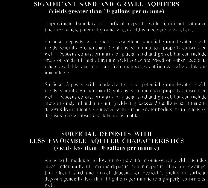
1 SECTION GROUNDWATER Groundwater A. Narrative The proposed project should not impact groundwater quantity or quality. As presented in Section 411.5, Stormwater Management of this application, stormwater runoff from the majority of the site will be directed into a grassed Underdrained Soil Filter (USF) and an existing infiltration basin for water quality treatment and runoff control. In addition, the outlet of the USF will be connected to an existing storm drain system which conveys the stormwater to Mare Brook. The USF will be lined with a non-pervious membrane preventing the degradation of the existing groundwater quality. The project boundaries have been delineated on the attached map entitled Figure , Town of Brunswick Aquifer protection Zones, NAS Brunswick, Maine, as found in the EIS. Also attached are maps of: Significant Sand and Gravel Aquifers, the Bedrock Geology of the Bath 1:1000,000 Quadrangle, Maine and the Surficial Geology map. No groundwater will be used, discharged or otherwise extracted by this development. The solid waste deposited at the facility will be handled in a manner that will contain the material on paved surfaces and will collect the solid waste in subsurface enclosed tanks prior to processing. There will be no other sources of potential contamination including hazardous materials, fuel, solvents or other chemicals handled, stored or disposed of on site. Dewatering activities during construction are the responsibility of the contractor conducting the work. Any dewatering will be directed to temporary sedimentation basins established throughout the construction site. B. Groundwater Protection Plan Not applicable. C. Monitoring Plan Not applicable. D. Monitoring Well Installation Report Not applicable. 15-1


2 Ecology & Environment, Inc. GIS Department Project # \L:\Buffalo\Brunswick\Maps\MXD\DEIS\Draft\January_2010\Chapter 3\Aquifer Protection Zones.mxd U.S. Route 1 Legend Installation Boundary Aquifer Protection Zone Buttermilk Cove Zone 1 Zone 2 County Boundary ,000 2,000 Feet Harpswell Cove Source: Town of Brunswick 2009a. Figure Town of Brunswick Aquifer Protection Zones NAS Brunswick, Maine
3
4
5
6 SECTION EROSION CONTROL Erosion Control A. Narrative A narrative addressing the measures and practices for the project s erosion and sedimentation control measures has been attached to this section. Also included in this section as attachments to the erosion and sedimentation control measures are the maintenance and housekeeping practices for the stormwater facilities. B. Implementation Schedule The implementation schedule is hinged on the construction start date and a detailed schedule from that date is provided within the Erosion and Sediment Control Notes provided on the plans. C. Plan of Existing Conditions and Plan of Proposed Conditions See drawings C-2 and C-3 depicting all existing and proposed site features, respectively. D. Plan of Locations of Erosion Control BMPs See drawing C-4 depicting the locations of all proposed temporary and permanent erosion control measures to be installed on the site. E. Plan of Limits of Areas to be Disturbed by Construction See drawing C-4 depicting the limits of areas to be disturbed by construction activities. F. Plan of Details and Specifications of Erosion and Sediment Control Measures See drawing C-6 for Notes and Details of Erosion and Sediment Control Measures. G. Design Calculations The erosion and sediment control measures to be implemented have been designed considering the peak flows presented in Section 411.5, Stormwater Management of this application and in accordance with the guidelines presented in the Maine Erosion and Sediment Control handbook for Construction: Best Management Practices (BMPs). Permanent measures such as Riprap outlet aprons were designed using the chart and guidelines provided in Section E-3 Pipe Outlet Protection. Emergency spillway riprap was sized considering the flows resulting from the spillway operating as the only outlet and computing a depth of flow over a typical spillway section. H. Third Party Inspection - Not applicable.
7 SECTION 411.7A EROSION AND SEDIMENTATION CONTROL PLAN Anaerobic Digester/Energy Production Facility Village Green Maine, LLC Brunswick Landing Brunswick, Maine INTRODUCTION This Erosion and Sedimentation Control Plan (E&S Plan) has been developed to provide a strategy to prevent unreasonable erosion of soil and sediment transport beyond the project site or into a protected natural resource. These strategies apply to the proposed development immediately prior to soil disturbing activities on the site and shall remain in place until the site is permanently stabilized. The information presented in this E&S Plan is provided as an overview of the anticipated measures to be used on this site. In some instances, additional measures may be required due to unexpected conditions that arise during construction. Also, specific detail on the application of a recommended practice for an unexpected instance may not be covered in this E&S Plan. For additional detail on any of the erosion and sedimentation control measures discussed in this E&S Plan or for further recommendations of applicable practices, refer to the Maine Erosion and Sedimentation Control BMP manual published by the Maine Department of Environmental Protection (MDEP) dated March 2003, as revised. 1.0 PLAN IMPLEMENTATION PHASES Generally, the implementation of this plan occurs in three distinct phases as described below: 1.1 Pre-construction Phase Prior to the beginning of any construction, perimeter sediment barriers (i.e. silt fence, erosion control mix berm, etc ) shall be installed at, or just below, the limits of clearing or grubbing, and/or just above any adjacent property line or protected natural resource. Prior to any clearing or grubbing, a construction entrance shall be constructed at the intersection with the proposed access drive and the existing roadway to avoid tracking of mud, dust and debris from the site. 1.2 Construction Phase Areas undergoing actual construction shall only expose that amount of mineral soil necessary for progressive and efficient site construction. Any area that has been disturbed and is not permanently stabilized (as described by this E&S Plan) shall be considered open. Open areas shall be protected and stabilized with temporary erosion and sedimentation control measures as shown on the project plans and as described within this E&S Plan. Preparation for winter stabilization applies to some disturbed areas that are open on or after September 15th of the construction season (refer to the Winter Construction Section of this E&S Plan, Paragraph B Overwinter Stabilization Timeframe). Any areas that remain open after November 1 or new soil disturbance that occurs after November 1, but before April 15, must be protected by additional measures as described in the Winter Construction section of this E&S Plan. The recommendations outlined in the Winter Construction section of this E&S Plan shall supersede other conflicting recommendations. Erosion and Sedimentation A Control Plan
8 1.3 Post-construction phase Once the site has reached permanent stabilization, remove any temporary sediment control measures, such as silt fence, within 30 days. All accumulated sediment/debris in the permanent stormwater management system, ditches, swales, paved surfaces, and/or any other location that has accumulated sediment/debris during construction shall be removed and disposed of in an approved manner. 2.0 PERMANENT STABILIZATION The strategies outlined in this E&S Plan shall be in effect until the site reaches permanent stabilization. Newly seeded or sodded areas must be protected from vehicle traffic, excessive pedestrian traffic, and concentrated runoff until the vegetation is well established. If necessary, areas must be seeded and mulched again if germination is sparse, plant coverage is spotty, or topsoil erosion is evident. The following list defines permanent stabilization for applicable situations. 2.1 Seeded Areas: For seeded areas, permanent stabilization means a 90% cover of vigorous perennial growth with no evidence of washing or rilling of the topsoil. 2.2 Sodded Areas: For sodded areas, permanent stabilization means the complete binding of the sod roots into the underlying soil with no slumping of the sod or die-off. 2.3 Permanent Mulch: For mulched areas, permanent mulching means total coverage of the exposed area with an approved mulch material. Erosion control mix may be used as mulch for permanent stabilization according to approved application rates and limitations. 2.4 Riprap: For areas stabilized with riprap, permanent stabilization means that slopes stabilized with riprap have an appropriate backing of well-graded gravel or approved geotextile to prevent soil movement from behind the riprap. 2.5 Paved Areas: For paved areas, permanent stabilization means the placement of compacted gravel subbase is completed. 2.6 Ditches, channels, and swales: For open channels, permanent stabilization means the channel is stabilized with a 90% cover of vigorous perennial growth, a well-graded riprap lining, or with another non-erosive lining such as specified. There must be no evidence of slumping of the channel lining, undercutting of the channel banks, or down-cutting of the channel. 3.0 TEMPORARY EROSION AND SEDIMENTATION CONTROL BMPS The placement/use of the following erosion and sedimentation control measures shall be in accordance with the Maine Erosion and Sedimentation Control BMP manual published by the Maine Department of Environmental Protection (MDEP) dated March 2003, as revised. 3.1 Sediment Barriers: Prior to the beginning of any construction, sediment barriers (i.e. silt fence, erosion control mix berms, etc ) shall be installed across the slope(s), on the contour, at or just below the limits of clearing or grubbing, and/or just above any adjacent property line or watercourse to protect against construction related erosion. Sediment barriers shall be maintained until all tributary open areas have been permanently stabilized. The following are recommended perimeter sediment barriers: Erosion and Sedimentation A Control Plan
9 Silt fence: Shall be installed per the detail on the plans. The effective height of the fence shall not exceed 36 inches. It is recommended that silt fence be removed by cutting the fence materials at ground level so as to avoid additional soil disturbance. Staked hay bales: Shall be installed per the detail on the plans. Bales shall be wire-bound or string-tied and these bindings must remain parallel with the ground surface during installation to prevent deterioration of the bindings. Bales shall be installed within a minimum four (4) inch deep trench line with ends of adjacent bales tightly abutting another. Erosion control mix berm: Shall be installed per the detail on the plans. The mix shall consist primarily of organic material and contain a well-graded mixture of particle sizes. The mix must meet the most recent composition specifications published by the MDEP. No trenching is required for installation of this barrier. 3.2 Surface Stabilization: All disturbed areas that will not be worked for more than 7 days shall be protected and stabilized with mulch or other non-erodable cover. Areas located within 75 feet of a wetland or waterbody must be protected and stabilized within 48 hours of the initial disturbance of the soil or prior to any storm event, whichever comes first. Areas that have been seeded (temporary or permanent) shall be stabilized immediately. The following are recommended practices for surface stabilization: Hay or straw Mulch: Organic mulches including hay and straw need to be air-dried, free of undesirable seeds and coarse materials. Application rate shall be 2 bales (70-90 lbs) per 1000 square feet or 1.5 to 2 tons ( bales) per acre. This type of mulch must be anchored with a tackifier amendment and/or via physical means (i.e. vehicle tracking, jute netting, etc ) to avoid displacement by wind or water. Erosion control mix: Erosion Control Mix can be manufactured on or off the site. It is composed primarily of shredded bark, stump grindings, composted bark, or other acceptable products based on a similar raw source. The mix must meet the most recent composition specifications published by the MDEP. The mix shall be placed evenly and must provide 100% soil coverage. Erosion control mix shall be applied such that the thickness on slopes 3:1 or less is 2 inches plus ½ inch per 20 feet of slope up to 100 feet. The thickness on slopes between 3:1 and 2:1 is 4 inches plus ½ inch per 20 feet of slope up to 100 feet. This shall not be used on slopes greater that 2:1. Erosion control blankets: Erosion Control Blankets are used on steep slopes (greater than 3H:1V) and also areas that will receive concentrated stormwater flows. Blankets aid in controlling erosion on disturbed soils and critical areas during the establishment period of vegetation. Various forms of erosion control blankets are commercially available, each with different advantages for different applications. The type of blanket to be used for individual applications shall be as indicated on the development plan set or via the use of an approved equivalent blanket. In all applications, the blanket manufacturer s specifications and installation methods shall be referenced and adhered to. 3.3 Soil Stockpiles: All topsoil shall be stockpiled for future use on the project at a stable location onsite. Structural measures, such as sediment barriers, may be warranted for additional sediment control of the stockpile areas. Stockpiles of soil or subsoil shall be mulched with hay or straw or with erosion control mix. This must be done within 24 hours of stocking and re-established prior to any rainfall. Any soil stockpile will not be placed (even covered with hay or straw) within 75 feet from any protected natural resources. 3.4 Stabilized Construction Entrance/Exit: Prior to any clearing or grubbing, a stabilized construction entrance/exit shall be constructed wherever traffic will exit the construction site onto a paved roadway in order to minimize the tracking of sediment and debris from the construction site onto public roadways. The entrances and adjacent roadway areas shall be periodically swept or washed to further minimize the tracking of mud, dust or debris from the construction area. Erosion and Sedimentation A Control Plan
10 When washing is required, it shall be done on an area stabilized with aggregate, which drains into an approved sediment trapping device. Stabilized construction exits shall be constructed in areas as specified and detailed on the plans. 3.5 Stone Check Dams: Stone check dams are generally temporary devices, which are constructed across a swale or drainage ditch. Their purpose is to reduce the velocity of concentrated stormwater flows, thereby reducing erosion of the swale or ditch. These devices will also trap small amounts of sediment generated in the ditch itself, however, they are not an effective sediment trapping device and should not be used as such. Stone check dams are typically constructed of 2-3 crushed stone and stand 24 inches in height. 3.6 Storm Drain Inlet Protection: Storm drains are typically operational prior to permanent stabilization of tributary areas. In these instances hay bales, crushed stone barriers, and/or silt sacks shall be used within a catch basin or prior to a pipe entrance. This temporary protection will assist in the removal of sediment prior to entrance into a storm drainage system and the prevention of clogging and/or loss of capacity. These devices alone will not prevent all sediment from entering the stormwater system and should be used in conjunction with other devices to achieve desired sediment removal levels. 3.7 Dewatering: Water from construction dewatering will pass first through a filter bag or secondary containment structure (e.g. hay bale lined pool) prior to discharge. The discharge site shall be selected to avoid flooding, icing and sediment discharges to a protected natural resource. Discharge is permitted within the filter basin locations prior to the installation of the filter media. 3.8 Dust Control: Dust control during construction shall be achieved by the use of a watering truck to periodically sprinkle the exposed roadway areas as necessary to reduce dust during the dry months. Applying other dust control products such as calcium chloride or other manufactured products are allowed if authorized by the proper local, state and/or federal regulating agencies. However, it is the contractor s ultimate responsibility to mitigate dust and soil loss from the site. 4.0 VEGETATIVE MEASURES 4.1 Temporary Vegetation: If any disturbed area of soil will be left bare for more than 7 days, or if construction is to be completed in phases over an extended duration, temporary seeding and mulching shall commence immediately following initial fine grading of the site. In sensitive areas (within 75 feet of protected natural resources) temporary mulch must be applied within 48 hours or prior to any storm event on all disturbed surfaces. It shall be maintained and reseeded, as necessary, to ensure good vegetative cover for the entire duration of construction. Seed will be selected from the following table (Table 1 - Temporary Seed Mixture) according to the time of year or via an approved equivalent method. TABLE 1 TEMPORARY SEED MIXTURE Seed Lbs./Acre Lbs./1000s.f. Recommended Seeding Date Winter Rye /15 thru 10/1 Oats /1 thru 7/1 8/15 thru 9/15 Annual Ryegrass /1 thru 7/1 Sudangrass /15 thru 8/15 Perennial /15 thru 9/15 Note: Some tree and shrub species may be desirable for sites primarily covered with sand and gravel. These methods shall be approved by the appropriate regulatory authority prior to use. Erosion and Sedimentation A Control Plan
11 4.2 Permanent Vegetation: Revegetation measures shall commence immediately upon completion of final grading of areas to be loamed and seeded. Revegetation measures shall consist of the following: Seedbed Preparation Four (4) inches of loam will be spread over disturbed areas and smoothed to a uniform surface. Loam shall be free of subsoil, clay lumps, stones and other objects over 2" in any dimension, and without weeds, roots or other objectionable material. Soil tests shall be taken at the time of soil stripping to determine fertilization requirements. Soil tests shall be taken promptly as to not interfere with the 7-day limit on soil exposure (48-hours adjacent to a protected natural resource). Based upon test results, soil amendments shall be incorporated into the soil prior to final seeding. In lieu of soil tests, soil amendments may be applied as shown below in Table 2: TABLE 2 RECOMMENDED SOIL AMENDMENTS Item Fertilizer (N-P205-K20 or equal) Ground Limestone (50% calcium and magnesium oxide) Application Rate 18.4lbs./1,000 s.f. 138-lbs./1,000 s.f. Work lime and fertilizer into the soil as nearly as practical to a depth of four (4) inches with proper equipment. Roll the area to firm the seedbed except on clay, silty soils or coarse sand Application of Seed Seeding: The seed mixture shown below in Table 3 shall be utilized for permanent seeding applications. Alternate seed mixtures may be utilized as approved. Refer to Appendix A of the MDEP Erosion and Sedimentation Control BMP manual for additional seed mixture options. TABLE 3 PERMANENT SEED MIXTURE Seed Type Application Rate Creeping Red Fescue 0.46 lbs/1,000 s.f. (20 lbs/acre) Red Top 0.05 lbs/1,000 s.f. (2 lbs/acre) Tall Fescue 0.46 lbs/1,000 s.f. (20 lbs/acre) Total: 0.97 lbs/1,000 s.f. (42 lbs/acre) Hydroseeding: Shall be conducted on prepared areas as described above. Hydroseeding shall not be done on slopes steeper than 2H:1V. Lime and fertilizer may be applied simultaneously with the seed. Recommended seeding rates must be increased by 10% when hydroseeding. Erosion and Sedimentation A Control Plan
12 Surface Stabilization: Mulching or other approved surface stabilization methods shall commence immediately after seed is applied. Refer to the surface stabilization section of this plan for more information Sodding 5.0 WINTER CONSTRUCTION Following seedbed preparation, sod can be applied in lieu of seeding in areas where immediate vegetation is most beneficial such as ditches, around stormwater drop inlets and areas of aesthetic value. Sod should be laid at right angles to the direction of flow starting at the lowest elevation. Sod should be rolled or tamped down to even out the joints once laid down. Where flow is prevalent the sod must be properly anchored down. Irrigate the sod immediately after installation. In most cases, sod can be best established between April 1 and November 15 of the construction year. The winter construction period is from November 1 through April 15. If the construction site is not permanently stabilized by November 15 then the site needs to be protected with over-winter stabilization. Winter excavation and earthwork shall be completed such that no more than 1 acre of the site is without stabilization at any one time. Limit the exposed area to those areas in which work is expected to be under taken during the proceeding 15 days and that can be mulched in one day prior to any snow event. All areas shall be considered to be denuded until the subbase gravel is installed in roadway areas or the areas of future loam and seed have been loamed, seeded and mulched. Any added measures, which may be necessary to control erosion/sedimentation from the site dependent upon the actual site and weather conditions, must be installed. Continuation of earthwork operations on additional areas shall not begin until the exposed soil surface on the area being worked has been stabilized, in order to minimize areas without erosion control protection. 5.1 Winter Construction BMP Adjustments 1) Sediments Barriers: During frozen conditions, sediment barriers shall consist of erosion control mix berms as frozen soil prevents the proper installation of hay bales and silt fences. 2) Mulching: Between the dates of November 1 and April 15, all mulch shall be anchored by either mulch netting, asphalt emulsion chemical, track or weed cellulose fiber. When the ground surface is not visible through the mulch then cover is sufficient. After November 1st, mulch and anchoring of all exposed soil shall occur at the end of each final grading workday. Open Surfaces (flatter than 8%): Hay and straw mulch shall be applied at a rate of 150 lb. per 1,000 square feet or 3 tons/acre (twice the normal accepted rate of 75-lbs./1,000 square feet or 1.5 tons/acre) and shall be properly anchored. Mulch shall not be spread on top of snow. The snow will be removed down to one-inch depth or less prior to application. After each day of final grading, the area will be properly stabilized with anchored hay or straw or erosion control matting. An area shall be considered to have been stabilized when exposed surfaces have been either mulched with straw or hay at a rate of 150 lb. per 1,000 square feet (3 tons/acre) and adequately anchored that ground surface is not visible through the mulch. Erosion and Sedimentation A Control Plan
13 Open Slopes (8% or steeper) and Drainage Ways: Slopes shall not be left exposed for any extended time of work suspension unless fully mulched and anchored with netting or erosion control blankets. Mulching shall be applied at a rate of 230-lbs/1,000 square feet on all slopes steeper than 8%. Mulch netting shall be used to anchor mulch in all drainage ways with a slope steeper than 3% for slopes exposed to direct winds and for all other slopes steeper than 8%. Erosion control blankets shall be used in lieu of mulch in all drainage ways. Erosion control mix can be used to substitute erosion control blankets on slopes that do not exceed 2H:1V. In this case, the erosion control mix shall be spread out, not placed in a berm as it is installed as a sedimentation barrier. 3) Soil Stockpiles: Stockpiles of soil or subsoil shall be mulched for over winter protection with hay or straw at twice the normal rate or at 150-lbs/1,000 square feet (3 tons per acre) or with a four-inch layer of wood waste erosion control mix. This will be done within 24 hours of stocking and re-established prior to any rainfall or snowfall. Any soil stockpile will not be placed (even covered with hay or straw) within 100 feet from any natural resources. 4) Natural Resources Protection: Any areas within 100 feet from any protected natural resources, if not stabilized with a minimum of 90% mature vegetation catch, shall be mulched by December 1 and anchored with plastic netting or protected with erosion control mats. During winter construction, a double line of sediment barriers (i.e. silt fence backed with hay bales or erosion control mix) will be placed between any natural resource and the disturbed area. Projects crossing the natural resource shall be protected a minimum distance of 100 feet on either side from the resource. Existing projects not stabilized by December 1 shall be protected with the second line of sediment barrier to ensure functionality during the spring thaw and rains. 5) Seeding: Between the dates of October 15 and April 1st, loam or seed will not be required. During periods of above freezing temperatures finished areas shall be fine graded and either protected with mulch or temporarily seeded and mulched until such time as the final treatment can be applied. If the date is after November 1st and if the exposed area has been loamed, final graded with a uniform surface, then the area may be dormant seeded at a rate of 3 times higher than specified for permanent seed and then mulched. Dormant seeding may be selected to be placed prior to the placement of mulch and fabric netting anchored with staples. If dormant seeding is used for the site, all disturbed areas shall receive 4 of loam and seed at an application rate of 5-lbs/1000 square feet. All areas seeded during the winter will be inspected in the spring for adequate catch. All areas insufficiently vegetated (less than 90% catch) shall be revegetated by replacing loam, seed and mulch. If dormant seeding is not used for the site, all disturbed areas shall be revegetated in the spring. 5.2 Overwinter Stabilization Timeframe 1) Ditches and Channels: All stone-lined ditches and channels must be constructed and stabilized on the site by November 15. All grass-lined ditches and channels must be constructed and stabilized by September 15. If a ditch or channel is not grass-lined by September 15, then one of the following actions must be taken to stabilize the ditch for late fall and winter. Erosion and Sedimentation A Control Plan
14 Install a sod lining in the ditch: A ditch must be lined with properly installed sod by October 1. Proper installation includes the contractor pinning the sod onto the soil with wire pins, rolling the sod to guarantee contact between the sod and underlying soil, watering the sod to promote root growth into the disturbed soil, and anchoring the sod with jute or plastic mesh to prevent the sod strips from sloughing during flow conditions. Install a stone lining in the ditch: A ditch must be lined with stone riprap by November 15. A registered professional engineer must be hired to determine the stone size and lining thickness needed to withstand the anticipated flow velocities and flow depths within the ditch. If necessary, the ditch must be regraded prior to placing the stone lining to prevent the stone lining from reducing the ditch s cross-sectional area. 2) Disturbed Slopes: All stone-covered slopes must be constructed and stabilized by November 15. All slopes to be vegetated must be seeded by September 15. The MDEP will consider any area having a grade greater than 15% (10H:1V) to be a slope. If a slope to be vegetated is not stabilized by September 1, then one of the following actions must be taken to stabilize the slope for late fall and winter. Stabilize the soil with temporary vegetation and erosion control blankets: By October 1 the disturbed slope must be seeded with winter rye at a seeding rate of 3 pounds per 1,000 square feet and apply erosion control blankets over the mulched slope. If the rye fails to grow at least three inches or cover at least 90% of the disturbed slope by November 1, the slope will be covered with a layer of erosion control mix or stone riprap as described in the following standards. Stabilize the slope with sod: The disturbed slope must be stabilized with properly installed sod by October 1. Proper installation includes pinning the sod onto the slope with wire pins, rolling the sod to guarantee contact between the sod and underlying soil, and watering the sod to promote root growth into the disturbed soil. Slopes steeper than 33% (3H:1V) or having groundwater seeps on the slope face, may not use late-season sod installation for stabilization. Stabilize the slope with erosion control mix: A six-inch layer of erosion control mix must be spread over the slope by November 15. Prior to placing the erosion control mix, any snow accumulation on the disturbed slope must be removed. Slopes steeper than 50% (2H:1V) or having groundwater seeps on the slope face can not use erosion control mix to stabilize slopes. Stabilize the slope with stone riprap: A layer of stone riprap can be placed on the slope by November 15. A registered professional engineer must be hired to determine the stone size needed for stability and to design a filter layer for underneath the riprap. 3) Other Disturbed Soils: By September 15, all disturbed soils on areas having a slope flatter than 15% (10H:1V) must receive seed and mulch. If disturbed areas are not stabilized by this date, then one of the following actions must be taken to stabilize the soil for late fall and winter. Stabilize the soil with temporary vegetation: By October 1, seed the disturbed soil with winter rye at a seeding rate of 3 pounds per 1,000 square feet, lightly mulch the seeded soil with hay or straw at 75 pounds per 1000 square feet, and Erosion and Sedimentation A Control Plan
15 anchor the mulch with plastic netting. Monitor growth of the rye over the next 30 days. If the rye fails to grow at least three inches or cover at least 90% of the disturbed soil before November 1, then mulch the area for over-winter protection as described in the following Stabilize the soil with mulch standard. Stabilize the soil with sod: Stabilize the disturbed soil with properly installed sod by October 1. Proper installation includes pinning the sod onto the soil with wire pins, rolling the sod to guarantee contact between the sod and underlying soil, and watering the sod to promote root growth into the disturbed soil. Stabilize the soil with mulch: By November 15, mulch the disturbed soil by spreading hay or straw at a rate of at least 150 pounds per 1000 square feet on the area so that no soil is visible through the mulch. Prior to applying the mulch, any snow accumulation on the disturbed area must be removed. Immediately after applying the mulch, anchor the mulch with plastic netting to prevent wind from moving the mulch off the disturbed soil. 6.0 INSPECTION AND MAINTENANCE Inspection and maintenance are required of all erosion and sedimentation control measures outlined in this plan. Refer to the Inspection, Maintenance, and Housekeeping plan for this project (provided under separate cover) for an outline of the associated inspection and maintenance requirements. Erosion and Sedimentation A Control Plan
16 Introduction SECTION 411.7B INSPECTION, MAINTENANCE, AND HOUSEKEEPING PLAN Anaerobic Digester/Energy Production Facility Village Green Maine, LLC Brunswick Landing Brunswick, Maine The following plan outlines the anticipated inspection and maintenance procedures for the erosion and sedimentation controls as well as stormwater management devices for the project site. Also, this plan outlines several housekeeping requirements that shall be followed during and after construction. These procedures should be followed in order to ensure the intended function of the designed measures and to prevent unreasonable adverse impacts to the surrounding environment. The procedures outlined in this inspection and maintenance plan are provided as an overview of the anticipated practices to be used on this site. In some instances, additional measures may be required due to unexpected conditions. For additional detail on any of the erosion and sedimentation control measures or stormwater management devices to be utilized on this project, refer to the most recently revised edition of the Maine Erosion and Sedimentation Control BMP manual and/or the Stormwater Management for Maine: Best Management Practices manual as published by the Maine Department of Environmental Protection (MDEP). During Construction 1. Inspection: During the construction process, it is the Contractor s responsibility to comply with the inspection and maintenance procedures outlined in this section. These responsibilities include inspecting disturbed and impervious areas, erosion control measures, material storage areas that are exposed to precipitation, and locations where vehicles enter or exit the site. These areas shall be inspected at least once a week as well as before and after a storm event, and prior to completing permanent stabilization measures. A person with knowledge of erosion and stormwater control, including the standards and conditions in any applicable permits, shall conduct the inspections. 2. Maintenance: All measures shall be maintained in an effective operating condition until areas are permanently stabilized. If Best Management Practices (BMPs) need to be maintained or modified, additional BMPs are necessary, or other corrective action is needed, implementation must be completed within 7 calendar days and prior to any storm event (rainfall). 3. Documentation: A log summarizing the inspections and any corrective action taken must be maintained on-site. The log must include the name(s) and qualifications of the person making the inspections, the date(s) of the inspections, and major observations about the operation and maintenance of erosion and sedimentation controls, material storage areas, Inspection, Maintenance and A Housekeeping Plan
17 and vehicle access points to the site. Major observations must include BMPs that need maintenance, BMPs that failed to operate as designed or proved inadequate for a particular location, and locations where additional BMPs are needed. For each BMP requiring maintenance, BMP needing replacement, and location needing additional BMPs, note in the log the corrective action taken and when it was taken. The log must be made accessible to the appropriate regulatory agency upon request. 4. Specific Inspection and Maintenance Tasks: The following is a list of erosion control and stormwater management measures and the specific inspection and maintenance tasks to be performed during construction. A. Sediment Barriers: Hay bale barriers, silt fences, and filter berms shall be inspected immediately after each rainfall and at least daily during prolonged rainfall. If the fabric on silt fence or filter barrier should decompose or become ineffective prior to the end of the expected usable life and the barrier is still necessary, it shall be replaced. Sediment deposits should be removed after each storm event. They must be removed before deposits reach approximately one-half the height of the barrier. Filter berms shall be reshaped as needed. Any sediment deposits remaining in place after the silt fence or filter barrier is no longer required should be dressed to conform to the existing grade, prepared, and seeded. B. Erosion Control Blankets: Inspect these reinforced areas semi-annually and after significant rainfall events for slumping, sliding, seepage, and scour. Pay close attention to unreinforced areas adjacent to the erosion control blankets, which may experience accelerated erosion. Review all applicable inspection and maintenance procedures recommended by the specific blanket manufacturer. These tasks shall be included in addition to the requirements of this plan. C. Temporary Storm Drain Inlet Protection: The inlet protection structure shall be inspected before each rain event and repaired as necessary. Sediment shall be removed and the storm drain sediment barrier restored to its original dimensions when the sediment has accumulated to half of the design depth of the trap. Barriers shall be removed upon permanent stabilization of the tributary area. Upon removal of the barrier, all accumulated sediments downstream of the structure shall be cleaned from the storm drain system. Inspection, Maintenance, and A Housekeeping Plan
18 D. Stabilized Construction Entrances/Exits: The exit shall be maintained in a condition that will prevent tracking of sediment onto public rights-of-way. When the control pad becomes ineffective, the stone shall be removed along with the collected soil material. The entrance should then be reconstructed. Areas that have received mud-tracking or sediment deposits shall be swept or washed. Washing shall be done on an area stabilized with aggregate, which drains into an approved sediment-trapping device (not into storm drains, ditches, or waterways). E. Temporary Seed and Mulch: Mulched areas should be inspected after rain events to check for rill erosion. If less than 90% of the soil surface is covered by mulch, additional mulch shall be applied in bare areas. In applications where seeding and mulch have been applied in conjunction with erosion control blankets, the blankets must be inspected after rain events for dislocation or undercutting. Mulch shall continue to be reapplied until 95% of the soil surface has established temporary vegetative cover. F. Stabilized Temporary Drainage Swales: After Construction Sediment accumulation in the swale shall be removed once the cross section of the swale is reduced by 25%. The swales shall be inspected after rainfall events. Any evidence of sloughing of the side slopes or channel erosion shall be repaired and corrective action should be taken to prevent reoccurrence of the problem. In addition to the stabilized lining of the channel (i.e. erosion control blankets), stone check dams may be needed to further reduce channel velocity. 1. Inspection: After construction, it is the responsibility of the owner or assigned heirs to comply with the inspection and maintenance procedures outlined in this section. All measures must be maintained in effective operating condition. A person with knowledge of erosion and stormwater control, including the standards and conditions in all applicable permits, shall conduct the inspections. 2. Specific Inspection and Maintenance Tasks: The following is a list of permanent erosion control and stormwater management measures and the inspection and maintenance tasks to be performed after construction. A. Vegetated Areas: Inspection, Maintenance, and A Housekeeping Plan
19 Inspect vegetated areas, particularly slopes and embankments, early in the growing season or after heavy rains to identify active or potential erosion problems. Replant bare areas or areas with sparse growth. Where rill erosion is evident, armor the area with an appropriate lining or divert the erosive flows to on-site areas able to withstand the concentrated flows. B. Catch Basins: Inspect and, if required, clean-out catch basins at least once a year, preferably in early spring. Clean out must include the removal and legal disposal of accumulated sediments and debris at the bottom of the basin, at any inlet grates, at any inflow channels to the basin, and at any pipes between basins. If the basin outlet is designed to trap floatable materials, then remove the floating debris and any floating oils (using oil-absorptive pads). C. Winter Sanding: Clear accumulations of winter sand in parking lots and along roadways at least once a year, preferably in the spring. Accumulations on pavement may be removed by pavement sweeping. Accumulations of sand along road shoulders may be removed by grading excess sand to the pavement edge and removing it manually or by a frontend loader or other acceptable method. D. Grassed Underdrained Soil Filters (USF1 & USF2) Check the pond embankments for sloughing or erosion. The vegetation should be well established and maintained. Remove any trees or shrubs growing in the pond or on the inside of the pond embankments. Check the outlet control structure for sediment accumulation or other blockages. Look for sediment deposits in the sediment forebays of the ponds. If the sediments leave less than 1 foot to the top of the berm between the forebay and the pond, remove the sediments and reline the forebay with stones. Monitor the time it takes for the stormwater takes to drain from the pond. For a 1inch or larger rainfall event, the pond should be drained in 24 to 48 hours. If the timeframe to drain the pond approaches 48 hours, the filter media should be replaced. Inspection, Maintenance, and A Housekeeping Plan
20 3. Duration of Maintenance: Perform maintenance as described and required for any associated permits unless and until the system is formally accepted by a municipality or quasi-municipal district, or is placed under the jurisdiction of a legally created association that will be responsible for the maintenance of the system. Housekeeping The following general performance standards apply to the proposed project both during and after construction. A. Spill prevention: Controls must be used to prevent pollutants from being discharged from materials and equipment on-site, including storage practices to minimize exposure of the materials to stormwater, and appropriate spill prevention, containment, and response planning and implementation. B. Groundwater protection: During construction, liquid petroleum products and other hazardous materials with the potential to contaminate groundwater may not be stored or handled in areas of the site draining to an infiltration area. An "infiltration area" is any area of the site that by design or as a result of soils, topography and other relevant factors, accumulates runoff that infiltrates into the soil. Dikes, berms, sumps, and other forms of secondary containment that prevent discharge to groundwater may be used to isolate portions of the site for the purposes of storage and handling of these materials. C. Fugitive sediment and dust: Actions must be taken to insure that activities do not result in noticeable erosion of soils or fugitive dust emissions during or after construction. Oil may not be used for dust control. D. Debris and other materials: Litter, construction debris, and chemicals exposed to stormwater must be prevented from becoming a pollutant source. E. Trench or foundation dewatering: Trench dewatering is the removal of water from trenches, foundations, cofferdams, ponds, and other areas within the construction area that retain water after excavation. In most cases, the collected water is heavily silted and hinders correct and safe construction practices. The collected water must be removed from the ponded area, either through gravity or pumping, and must be spread through natural wooded buffers or removed to areas that are specifically designed to collect the maximum amount of sediment possible, like a cofferdam sedimentation basin. Avoid allowing the water to flow over disturbed areas of the site. Equivalent measures may be taken if approved. Inspection, Maintenance, and A Housekeeping Plan
21 Project Construction Erosion Control BMPs Inspection Maintenance Tasks Log Village Green Maine, LLC Inspector: Anaerobic Digester/Energy Production Facility Brunswick Landing Brunswick, Maine W-P Date: Maintenance Personnel: Erosion Control BMPs Date Inspection Comments Date Maintenance Corrective Action Silt Fence/Hay Bales/Mulch Soil stockpiles Construction Site Entrance Cut/Fill Slopes Protection Vegetated/Riprap Ditches Stone Check Dams Catch Basins/Manholes Inlet Protection Road Sideslopes Protection Outfall Condition Soil Filter Embankments Stability General Site Stability Riprap Condition Culvert Conditions Erosion Control Blankets Temporary Seeding & Mulch Sediment/Debris Disposal Location of Sediment/Debris Accumulation Location of Sediment/Debris Disposal Date of Disposal Page 1 of 1
22 Post Project Construction Erosion Control Inspection and Maintenance Tasks Log Village Green Maine, LLC Inspector: Anaerobic Digester/Energy Production Facility Brunswick Landing Brunswick, Maine W-P Date: Maintenance Personnel: Permanent Erosion Control Measures Date Inspection Comments Date Maintenance Corrective Action Repair Eroded Vegetated Slopes Replant Bare or Sparsely Vegetated Areas Remove Accumulated Sediment in Catch Basin Remove Winter Sand and Debris Repair Soil Filter Embankments Remove Sediment at Soil Filter Outlet Remove Sediment from Soil Filter Forebays Remove Sediment on Soil Filter Surface Replant Soil Filter Vegetation Remove Sediment and Debris from Ditches Remove Woody Growth from Ditches Remove Obstructions from Culvert Inlets-Outlets Repair Any Other Site Stability Problem Areas Sediment/Debris Disposal Location of Sediment/Debris Accumulation Location of Sediment/Debris Disposal Date of Disposal Page 1 of 1
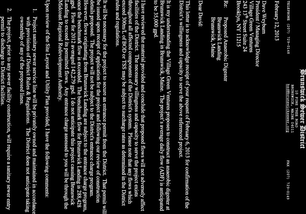
23 SECTION SEWAGE DISPOSAL Sewage Disposal A. On-site Subsurface Wastewater Disposal Systems Not applicable. B. Nitrate-Nitrogen Impact Assessment Not applicable. C. Municipal Facility or Utility Company Letter The proposed Anerobic Digestor/Energy Production Facility is designed to anaerobically digest a mixture of pumpable organics and site macerated solid organics to produce electricity and stabilized digestate effluent that will be land-applied. Effluent liquids from the system and the minimal amount of wastewater discharged from the proposed 50 x 50 operator s station, housing an office area, bathroom, pumps and heat exchanger, will be directed to the Brunswick Sewer District (BSD). It is proposed that the facility will tie into the BSD system through the existing Brunswick Landing wastewater disposal infrastructure. The facility has an anticipated average daily flow of 35,000 gal./day of liquid effluent per day. The Brunswick Sewer District has provided the attached letter stating their ability to serve the project s anticipated demands. D. Wastewater Discharge Information. The development will not discharge any liquid waste into any stream, river, pond, lake or other body of water including tidal waters. E. Storage or Treatment Lagoons Not applicable. 17-1
24
25
26 SECTION WATER SUPPLY Water Supply A. Water Supply Method The water supply for the proposed facility will be provided by MRRA which operates the water distribution system at Brunswick Landing. MRRA obtains the water from the Brunswick and Topsham Water District through a connection to the existing Brunswick Landing water supply infrastructure. Reference is made to the attached letter from the Brunswick and Topsham Water District confirming that it has the capacity to server the proposed facility. B. Subsurface Wastewater Disposal Systems Sewer services will be provided by the Brunswick Sewer District. C. Total Usage Water usage at the proposed facility will be minimal and will be limited to that needed to supply the small operations office on site, typically in the order of 200 gallons per day. 16-1

27 Alan J. Frasier, PE General Manager Craig W. Douglas, PE District Engineer PO Box 489 Topsham, Maine Telephone (207) Fax (207) Daniel O. Knowles, CPA Director of Finance and Data Management Systems William G. Alexander, Jr. Operations Manager December 17, 2012 Jan B.S. Wiegman PE Wright-Pierce 99 Main Street Topsham, ME Via RE: Proposed Brunswick Landing Phase 1 Subdivision Project, Brunswick Dear Mr. Wiegman: This letter is to inform you that the District has the ability to serve the referenced project, and will provide service in accordance with Maine Public Utilities Commission and Brunswick & Topsham Water District Rules and Regulations. Your previous correspondence acknowledge that the flow requirements of the proposed project are not known at this time, but generally anticipate that the requirements would be of a scale similar to the former naval air station. Given this, the District is capable of taking on this additional use. Also, it is not clear if this project obtains service from a private main. Please be advised we cannot ensure the reliability of the infrastructure beyond the connections made directly to our system. We will gladly discuss the options for service and main extensions when the project is ready to proceed. Please keep us informed as this project progresses. If you have any questions, please call. Yours truly, Craig Douglas PE District Engineer Cc: Eric Gagnon QUALITY AND RELIABILITY SINCE 1903
28 PAUL R LEPAGE GOVERNOR STATE OF MAINE DEPARTMENT OF INLAND FISHERIES & WILDLIFE 284 STATE STREET 41 STATE HOUSE STATION AUGUSTA, MAINE 04333:0041 CHANDLER E. WOODCOCK COMMISSIONER October 19, 2012 Jan Wiegman, P.E. Wright-Pierce 99 Main Street Topsham, ME RE: Information Request, Anaerobic Digester/Energy Production Facility Dear Jan: Per your request received October 19 we have searched current Department records for known occurrences of Rare, Threatened, and Endangered species, designated Essential and Significant Wildlife Habitats, and fisheries habitat concerns within the vicinity of the proposed anaerobic digester/energy production facility at Brunswick Landing in Brunswick. Our records indicate no occurrences of rare, threatened, or endangered animal species within the project area. Additionally, our department has not mapped any Essential or Significant Wildlife Habitats or Fisheries Habitats that would be directly impacted by your project. This consultation review has been conducted specifically for known MDIF&W jurisdictional features and should not be interpreted as a comprehensive review for the presence of all regulated features that may occur on site. Prior to the start of any future site disturbance we recommend additional consultation with the municipality, and other state resource agencies including the Maine Natural Areas Program and Maine Department of Environmental Protection in order to avoid unintended protected resource disturbance. Please feel free to contact my office if you have any questions regarding this information, or if I can be of any further assistance. Best regards, Steve Walker Acting Environmental Review Coordinator
 Maine Departrnent of Inland")
29 etery plluidasdplper Upland Sanyp4rr Up?and Sandp1p7 Up and Sandpiper' no v EY iri Acadlan S arner 9;ati ltrnarlh esharpard Se th MO. 11( Epstasi Environmental Review of Fish and Wildlife Observations and Priority Habitats Project Name: Brunswick Landing Anaerobic Digester (Version 1) Maine Departrnent of Inland 19sheries and Wildlife Miles Prc4ectIon: UN, NAD83, Zone 19N Date: 10/19/2012 ProjectPoints CI Deer Winter Area ProjectLines 1.0 LURC P-fw ProjectPolys Cooperative DWAs _ ProjectsearchAreas CI Seabird Nesting islands Shorebird Areas inland Waterfowl/Wading Bird Shoreland Zoning_iwwh Tidal Waterfowl/Wading Bird Significant Vernal Pilots CI CI Roseate Tern Piping Plover/Least Tern CI Aquatic ETSc (2.5 mi review) 111 Rare Mussels (5 mi review) CI A and B Ust Ponds In Arctic Charr Habitat E. Brook Trout Joint Venture Subwatershed ClassfficatIon CI Environmental Review Polygons CI Wild Lake Trout Habitats Redfin Pickerel/Swamp Darter Habitats (buffer109ft) Special Concern-occupied habitats(100ft buffer)
30 WRIGHT-PIERCE -=.- Z-.1 7 Engineering a Better Environment Water Wastewater Infrastructure October 15, 2012 W-P Project No A Mr. Earle G. Shettleworth, Jr. Maine Historic Preservation Commission 55 Capital Street State House Station 65 Augusta, Maine Subject: Village Green Maine, LLC Anaerobic Digester/Energy Production Facility Brunswick Landing, Brunswick, Maine Dear Mr. Shettleworth: Wright-Pierce, at the direction of Village Green Maine, LLC, is preparing a Site Location of Development permit application for a proposed anaerobic digester/energy production facility at the former Naval Air Station Brunswick, now Brunswick Landing. The project site is located on the southerly end of the existing tarmac at the airport. Access to the site will be provided by upgrading an existing roadway leading northerly from the existing Brunswick Landing road system. The project will involve amending an existing Maine Department of Environmental Protection (DEP) Site Location of Development permit covering numerous projects undertaken at the airport facility. We would like to take this opportunity to solicit comments from the Maine Historic Preservation Commission regarding the potential impacts the project might have on historical resources in the vicinity of the project. We are planning to submit a Site Location of Development Permit application in November 2012 and anticipate that construction will be underway in early We are enclosing a location map and a conceptual site plan showing the proposed facility in relation to the greater Brunswick Landing property. Please let us know if you require any additional materials to properly carry out your evaluation of this site. Very truly yours, WRIGHT-PIERCE,e's Ca i olb\ J B. Wiegman, P.R.% Project Manager Based on the information submitted, I have concluded that there will be no historic properties affected by the proposed undertaking, as defined by Section 106 of the National Historic Preservation Act. Consequently, pursuant to 36 CFR 800.4(d)(1), no further Section 106 consultation is required unless additional resources are discovered during project implementation putsuant to 36 CFR Kirk F. Mohney, Deputy State Historic Preservation Officer Maine Historic Preservation Commission JBW/ Enclosures cc: David Weyburn Village Green Maine, LLC and Alan Johnson Quasar Energy Group Date Offices Throughout New England j 99 Main Street Topsharn, ME USA Phone I Fax


31
32

33


34
35
36 MH MH
37 t I' s :). FRP ON Ur APA i FRP ON 1 /2-APA RATED PL0 0/000. fpated PLYWOOD. 3-5/8. METAL 3-5/3- METAL STUDS 0 1r 04. STUDS 00 1S' 00. U. INSULATED split-face1.1asonry FRP ON 1/7 APA RATED PLMOOD. SSW METAL istiuyedsr s O.C. GYPSUM BOARD MASONRY FURRING FULL HEIGHT PARTITION FULL HEIGHT PARTITION V VINYL FACED FIBERGLASS INSULOTION * 1figa MEW- STUDS METAL LINER PANEL ONTERIOR) METAL SIDING SYSTEM (EXTERIOR) SOLIDS RECEIVING PIT STAIR WELL SCALE: 3/4,13 SCALE: 3/4,13 SCALE: 314, 1,0" SCALE: 3/4,f-0' 0 FRP ON 1/2' IPA RATED PL /IC METAL STUDS LAYER 500 GYPSUM BOARD FULL HEIGHT PARTITION c.., quasar energy gd,up quasar energy group 7624 Riverview Road PO Box Cleveland OH Phone: Scale: SEE DETAIL 0 Thls drautne contains valuable conndental and prop0m0y Information that 00=00 quasar energy greap. Is Masan and Is subject to a separate Confidentialty and Nendisolostre Agreernent quasar is es avthor and ormer of thls drawing, and retains atl common Wmstatutory and other dotsand prinleges wial respect hereto. inc100.0 mortis me Intormaron contained herek Hay not at env tee be used for any unauthorized impose, nor reproduced by or pro000o any third par0,.0000 P1ia000 roc sent of quasar. DS NATH SPLASH o BLOCK (TYR) 1V-Dk AIR COMPRESSOR. SEE SP-2 Oa Auk I r 1. ra & ( los ) if a 0 D e packag D HYDRONIC SYSTEM CEDER 4 I I 1111 CHP container rk Ile Ci ' 5< 27< ee raracirsnara pan HEAT EXCHANGER, SEE HVAC DRAWINGS - - AMON F SOUDS ni RECEIVING PIT 0 la =I I 1 FINISH FLOOR HEAT G LOOP EXPAN ON TANK 1.111M 111 I o EVO H n e!, _ 17 e 4,0" S VOCE = SI DEEP SUMP PIT PUMP OYP.) in A'. Ma PLANT MEI 1 FINISH FLOOR =SSW 1 CONTROL JOINT SEE DETAIL 6/S-S ELEVATIONS FOR APPROXIMATE LOCATIONS AND SPACING e Ire 22,0 ' IL fr ill 20000r mu N. SEPTAGE RECEINNG ;4. 12,000 GALLON F- / I I I 40 \ JO' ale NOTE 6 e 102 ) co A 1. SEE ,0' ' I WO )., _Li A MANUFACTURER'S U L L DRAWNGS FOR MMIERIIIIIMEMIIIIIMIIIIIIIIIII 1 D 4 EXACT LOCATION OF Ire ISSUED FOR BUILDING DEPT. 3/1/13 ( MI ).." EQUIPMENT TD r, WATER HEATER ri..011k T-0' -7 a ON SHELF ED / Rev. ECN Number Date 2. SEE srre DRAWINGS IA. I la ABOVE US.1 _i '11411IPI FOR EXACT PB 4. PTAC LOCATION OF CRP ill.) A CONCRETE PAVING. a SEE SITE DRAWINGS - \ \ I 0 UNISEX FLOOR PLAN [LP IS", N PANEL p.i ADA 5' - ACCESSIBLE -I OFFICE t2 RESTROOM ft 0.4 ILO I CJ Y its lior wir <0 Fo 4Zk ell OFD CP.1 0 t WATER SERVICE I 103 ) nsm 02124AVS: irrap W ill ril 0062iBRU-ME-12 Bninswick Landing ADS Facility ig ei, 14,S' IS 14,8' 0 t-o FLOOR PLAN r LIQUID STORAGE TANK zi Ho 1610 FILTER I RANI! NI. Ce, - a 0 k Orion Street Brunswick, ME RN Zt ak W BE Projec BRU.ME.11 BRUNSWICK LANDING1CURRENT DRAWING SET ICONSTRUCTIONABRUNSWICK ARCHITECTURALS. dwg GIS 255 PM 02013, Quasar Energy Group, LLC. All rights reserved.
38 <41) <41) RIOGS VENT STANDING SEAM METAL ROOF (COLOR -BLACK) (TVA) qt.iasar energy group quasar energy group 7824 Riverview Road PO Box Cleveland OH Phone: EA. 0 0 SPLIT-FACE ACCENT MASONRY (TYE( (COLOR - OYSTER) Nssdisds.r.AaSr.c.ale: SEE DETAIL FINISH FLOOR I 1 \ SPLIT-FACE MASONRY (COLOR -POLAR WHITE) SEAL VATH CLEAR SEALANT(TYPJ SPLIT-FACE ACCENT MASONRY (TYPT: (COLOR - OYSTER) This duning conta)ns AGAIN. confidenta1 and Gopnatuy brorm.e... the belc.ns. Is q...n.r.ray emu?. Ils rquasarl, and Is subject ta a separate ccana.tairty 0.0 meal quasar Is A. author and owner setianclemtitzettrisswiticorpzhelaw1;totintiurydinaynd Isprigh ls. The hlonraten endued hereh may not at an IAA A. used fa any unauthoned purpose, net repreduced by or preteed to lany thircl party. W pm. mitten consent olquaset T 0 ( 100 ) i \ SMOOTH CONCRETE L 1 i ELEVATION i i 0 ± SCALE 1/4,1,0' L J J BELOW FIN. FL AN/ ',ZS' Ce, N - Q) (fr" t CO CO Q G.H.... SOW RIDGE VENT EAVE TO BE GREEN GYP _..._ CJ e E IA li 1111 Ill PUT-FACE ACCENT A CI MASONRY (TYE (COLOR OYSTER) 0 SPLIT-FACE MA ONRY (COLOR -POLBR WH 7E) SEAL1MT4 CLEAR SEALANT(TYP2 Rev. ennagam. ISSUED FOR BUILDING DEPT. ECN Number ELEVATIONS 311/13 Date GUTTER A FINISH 7 El FLOOR e SPLIT-FACE ACCEN MASONRY (TYE) (COLOR OYSTER) fa PTAC-1 GRILLE SET 13" AFF 7 SMOOTH CONCRETE PnAu BRU-ME-12 Brunswick Landing ADS Facility _... Orion Street Brunswick. ME _.,- `..._..., BELOW FIN. FL ELEVATION SCALE: 1/0, h.. RAMII us.. GA al RN a W 02013, Quasar Energy Group, LLC. All rights reserved.
39 RIDGE VENT EAVE TO BE GREEN (TYR)..--"--..._, a._ quasar energygroup quasar energy group 7624 Riverview Road PO Box Cleveland OH Phone: GUTTER L4 SET BOTTOM 0:-C AFF PUT CE ACC NT.AIM MASONRY (TYP.) (COLOR - OYSTER) Scale: SEE DETAIL SORRY (C/J ILTO-FRA-CPEOLAR WARE)...--" SEAL WITH CLEAR SEALANTITYP.I T. MPSONRY ITYP.) CJ (COLOR - OYSTER/ I This draxing contains valuable sonaclanial PA proadatary informaann That belongn W quasar enenfly PPP. Ia rquasan. and is subject to a aslant. Caradanaaala and No rapplosurs Agreement. quasar is the author and owner of this drawing. and retains all aonamon law. stall/wry and ether /tab and prialkara aaal reapaat anat.. Inalaang ropyrighe. The int!donator cordainscl Wain may not at any trne be used for any uravaprizad pumas,. nor reproduced by or provided to any thad Pada. PaloalOP PPP amain consent egg..., 6 si5 FINISH ruaog Li 0 L ELEVATION -sesta tn.," j a,, B 0 F /lb %cicyceo Co, RIDGE VENT 121 r j- L \ SMOOTH CONCRETE L HII HIIIIIHI I r J I _1.- O STANDING SEAM ME AL R OF (COLOR - BLA Hi MAI 1 1 EF-1 SET BOTTOM 0 SW AFF 1 SPLIT-FACE ACCEN MASONRY (TYR) (COLOR - OYSTER]..-- SPLIPFACE MASONRY..." (COLOR. POLAR AMITE).../.. SEAL NATH CLEAR SEALANT(TYP 5 SPLIT-FACE ACCENT MASONRY (TYP.) (COLOR - OYSTER)... % ELEVATION 0 O S T Ep. MP mo. LI B NOITL CE ER NHTOEOR K LINE e ST AF F. EAVE --..., RAMII ihi. BELOW FIN. FL. 1 _I II.. FINISH FLOOR A A 0 ISSUED FOR BUILDING DEPT. 3/1 /13 Rev. ECN Number Date... ELEVATIONS rmiect lame vid ef an 0062-BRU-ME-12 Brunswick Landing ADS Facility Orian Street Brunswick, ME ,,,...4 RN (A4) Quasar Energy Group, LLC.Ag rights reserved. BE Projedel0042-BRU-ME-11 BRUNSWICK LANDINGICURRENT DRAWING SET ( CONSTRUCTIONABRUNSWICK ARCHITECTURALSAwg P M A

40 Creating opportunities for people and places since 1977 February 21, Water Street P.O. Box 268 Wiscasset, Maine fax Maine Department of Environmental Protection 17 State House Station Augusta, ME RE: Site Location of Development and Solid Waste Processing Facility Permits, Village Green Brunswick Landing, LLC. Dear DEP Staff, Coastal Enterprises, Inc. (CEI) has been working with the principals of Village Green Brunswick Landing, LLC (VGBL) on development of the proposed anaerobic digester project at Brunswick Landing, Brunswick, ME since CEI has an institutional commitment to further development of renewable energy technologies in Maine, especially those such as anaerobic digestion that simultaneously address solid waste storage issues. We have been impressed by the capacity of VGBL s principals to steadily move this complex project forward. Later this month, CEI Lending will consider an initial six-figure loan to VGBL for pre-development activities. As the project moves ahead, CEI expects to consider a construction funding request from VGBL and to play a central role in the larger lending consortium necessary to bring the development to completion. This letter is not a commitment to lend on CEI s part, but does represent our active engagement with this development project. Sincerely, Michael Finnegan Senior Vice President, Lending Senior Loan & Investment Officer A private, nonprofit community development and financial institution providing capital, technical assistance and advocacy for people, businesses and communities outside the economic mainstream. CEI is an equal opportunity provider.
41 fit MRRA In II/ ItIn Midcoast Regional Redevelopment Authority Date: June 28, 2012 General Land Lease Term Sheet Lessor: Lessee: Midcoast Regional Redevelopment Authority Village Green Maine, LLC Address: th St. # 24 Brooklyn, NY Premises: Lease Rate: Collateral Assignment Of Lease: Term: Lease Execution Date: Conditions Precedent To Lease: Approximately acres (approximately 87,120fe). The property is identified as property within the airport boundary and bounded on Orion Drive south, building 153 and airport apron and taxiways. SOISIft2 Collateral assignment of the lease is subject to restrictions of the Federal Aviation Administration. Fifteen year initial lease term. To be established, but in any event no later than July, 1, 2013 unless closing is delayed by actions of the Lessor. Standard lease provisions. Lessee will be responsible for obtaining all licenses, permits from Federal, State, and Local Governments to the satisfaction of the Lessor. Costs: All Lessor cost to be borne by the Lessee, including but not limited to: any required appraisals, survey and legal fees. Lessee will pay for the cost of all infrastructure including, but not limited to: site improvements, road, drainage, water, sewer, power line, and natural gas including hook up and interconnects. Taxes: Use: All federal state and local taxes are the responsibility of the Lessee Construction and operation of a commercial anaerobic digester Fitch Avenue Brunswick, ME IN Fax: info@mrra.us From Navy Base to a Great New Place!
42 MRRA Midcoast Regional Redevelopment Authority Executed Lease: The parties will not execute a lease, until completing their due diligence, including Lessor's obtaining sufficient comfort that all preconditions noted above are satisfied, and financial due diligence proves to the Lessor's satisfaction at its sole discretion that the Lessee has the capacity to undertake, complete and operate the facility or that sufficient liquidity coverage is provided to address the Lessor's risk concerns and Lessee's obtaining sufficient comfort that Lessor has title adequate to convey an unencumbered leasehold interest in the premises, and that the premises are fit for the intended use and free from environmental hazards and potential liabilities. The parties do not intend to create an enforceable tease until they negotiate a formal lease agreement. Subleasing: Signage: Brokerage Commission: Good Faith Deposit: Expiration: The Lessee will not be permitted to sublease or transfer its interest in the leased property for its current or any other use without the consent of MRRA and the Federal Aviation Administration. Consistent with Brunswick Landing Design guidelines and Town Zoning. No brokerage commission is paid on the Leasing of this property. The Lessee will remit with the acceptance of this Term Sheet a deposit of $1.111 which shall be applied to the transaction and/or closing cost. Any balance is nonrefundable if this transaction does not close. This Term Sheet expires on July 31, 2012 unless executed. Seen and agreed: Village Gr %vet- Date: 5450 Fitch Avenue Brunswick, ME Fax: info@mn -a.us From Navy Base to a Great New Place!
43
44
45 SCHEDULE A A certain lot or parcel of land with the improvements thereon situate northwesterly of Orion Street at Brunswick Landing, so-called, in the Town of Brunswick, Cumberland County, State of Maine, and being bounded and described as follows: BEGINNING at the intersection of the proposed northwesterly right-of-way line of Orion Street with the westerly line of land of Midcoast Regional Redevelopment Authority (MRRA), reference deed recorded in Cumberland County Registry of Deeds (CCRD) in Book 29438, Page 1, said land being described as parcel AIR-9 in said deed, said intersection being shown on a plan entitled Boundary Survey of a Portion of Land of U.S. Navy at Naval Air Station Brunswick, Maine to be Conveyed to the Midcoast Regional Redevelopment Authority, Brunswick, Maine (Cumberland County), dated January 14, 2011, by Sitelines, PA, Brunswick, Maine (Sitelines Plan), all as shown on a plan entitled Existing Conditions & Boundary Plan, Village Green Brunswick Landing LLC, Village Green Maine LLC, Digester/Generation, Brunswick, Maine, dated April 12, 2013, revised May, 2013, by Wright-Pierce (VGM Plan); Thence N E crossing other land of MRRA, reference deed recorded in CCRD in Book 28607, Page 1 (28607/1), a distance of feet to the TRUE BEGINNING POINT of the parcel hereinafter described; Thence S W crossing said other land of MRRA a distance of feet; Thence N W crossing said other land of MRRA a distance of feet; Thence N E crossing said other land of MRRA a distance of feet; Thence S E crossing said other land of MRRA a distance of feet to the TRUE BEGINNING POINT, containing 3.47 acres, more or less. Also granting an EASEMENT for the drainage of stormwater as it will exist after construction of the proposed improvements on the hereinabove described parcel, said EASEMENT to allow for the drainage of stormwater over, and across said other land of MRRA (28607/1) and for the drainage of stormwater into the existing storm drain system of MRRA, a portion of which storm drain system passes under and through the hereinabove described parcel. Also granting an ACCESS & UTILITY EASEMENT, to be used in common with others, to allow for the construction, use, maintenance, replacement, and reconstruction of a driveway and for the use and maintenance of the southerly 35 feet of the existing concrete tarmac adjoining the easterly line of the hereinabove described parcel, and to allow for the installation, construction, use, maintenance, replacement and reconstruction of utility services and appurtenances, including a sewer force main, a gas line, water lines and electrical and communications lines, from the proposed westerly right-of-way line of Orion Street in a general westerly direction in, on, over or under said first-mentioned land of MRRA (29534/1) and said other land of MRRA (28607/1), to the easterly line of the hereinabove described parcel, said ACCESS & UTILITY EASEMENT area being shown on said VGM Plan, and is further bounded and described as follows:
46 BEGINNING at a point on the easterly line of the hereinabove described parcel, said point being S E and feet as measured along said easterly line from the northeasterly corner of the hereinabove described parcel; Thence N E crossing said other land of MRRA (28607/1) a distance of feet to a point of curvature; Thence in a general northeasterly direction crossing said other land of MRRA (28607/1) along a curve to the left having a radius of feet through a central angle of an arc distance of feet to a point and the proposed westerly right-of-way line of Orion Street, said point being N E a chord distance of feet from the last-mentioned point; Thence S W along the proposed westerly right-of-way line of Orion Street a distance of feet to a point of curvature; Thence in a general southwesterly direction along the proposed northwesterly right-of-way line of Orion Street, along a curve to the right having a radius of feet through a central angle of an arc distance of feet to a point of reverse curvature, said point being S W a chord distance of feet from the last-mentioned point; Thence in a general northwesterly direction crossing said first-mentioned land of MRRA (29534/1), along a curve to the left having a radius of feet through a central angle of an arc distance of feet to a point, said point being N W a chord distance of feet from the lastmentioned point of reverse curvature; Thence N E crossing said first-mentioned land of MRRA (29534/1) and said other land of MRRA (28607/1) a distance of feet to the easterly line of the hereinabove described parcel; Thence N E the easterly line of the hereinabove described parcel a distance of feet to the point of beginning, containing 34,454 square feet, more or less. Reserving to the Midcoast Regional Redevelopment Authority (MRRA), a 20-foot wide STORM DRAIN EASEMENT, within the hereinabove first-described parcel, to allow for the use, maintenance, replacement, and reconstruction of an existing storm drain system and appurtenances thereof, said STORM DRAIN EASEMENT area to be centered on the existing storm drain pipes, and is as shown on the VGM Plan. Bearings are oriented to Grid North, Maine State Plane Coordinate System, West Zone, (NAD 83), as referenced on said Sitelines Plan. Being a portion of the premises described by Quitclaim Deed of the United States of America, acting by and through the Secretary of the Navy, Base Closure Program Management Office Northeast, Philadelphia, PA, to the Midcoast Regional Redevelopment Authority, dated September 30, 2011, recorded in Cumberland County Registry of Deeds in Book 28607, Page 1.
47
 27\" (68.6 crn) 13\" (33 0 ern) 5\" (12.")
48 D-Series Size 1 Mast Arm Mount LED Area Luminaire 4* nan axy Dr1,901)9 11 " 1111 IV; Catabg Number Notes Type Introduction EPA: Length: Width: Height: Weight (max): d"series Specifications 0.9 ft2 (0.08 ev) 27" (68.6 crn) 13" (33 0 ern) 5" (12.7 cm) 26 lips (1 1 8 kg) Ordering Information The modern styling of the D-Series is striking yet unobtrusive - making a bold, progressive statement even as it blends seamlessly with its environment. The D-Series distills the benefits of the latest in LED technology into a high performance, high efficacy, long-life luminaire. The outstanding photometric performance results in sites with excellent uniformity, greater pole spacing and lower power density. It is ideal for replacing W metal halide in pedestrian and area lighting applications with typical energy savings of 65% and expected service life of over 100,000 hours. EXAMPLE: DSX1 LED 2 30B700/40K 5R3 MVOLT MA DDBXD DSX1 LED Series Light Engines Performance Package ' Distribution Voltage Mounting Options Finish DSX1 LED 1 2 One engine (30 LEDs) Two engines (60 LEDs) 530 ma options: /30K / K / K 700 ma options: / K /40K 4000K 30B700/50K 5000K SR2 Type 0 SR3 SR4 SR5 FT Type Ill Type IV Type V Forward throw MVOLT I ' ' 480 ' Shipped included MA Mast arrn mounting Shipped installed (blank) DMG PER No NEMA twist-lock receptacle (decorative cover), wildlife shield, trigger latch, and bridge fitter. 0-10V dimming driver (no controls)" NEMA twist-lock receptacle only (no controls) DCR Dimmable and controllable via ROAM (no controls) ' HS House-side shield " WTB DS BUBLVL Utility terminal block Dual switching u External bubble level DDBXD DBLXD MOD DWHXD DDBTXD DBLBXD ONATXD DWHGXD Dark bronze Black Natural aluminum White Textured dark bronze Textured black Textured natural aluminum Textured white Accessories Ordered and shipped 1 Configured with 4000K(/40K) provides the shortest lead times. Consult factory for 3000K 1/301(3 and 5000K (/50K) lead times. Slug 10 00P112 W Pole-mounted motion/ambient sensor, 8-15' mounting height, MVOLT 2 MVOLT driver operates on any line voltage from V 150/ (specify finish) 3 Not available with single board, 530 ma product ). SOOR 600P 82 W Pole-mounted motion/ambient sensor, 15-3Omounting heigh( MVOLT 4 Not available with 347 or 4-801/. (specify finish) 5 Specifies a ROAM@ enabled luminaire with 0-10V dimming capability; DSS124F 1.51)1F U Phstoell-SSL twist-lock, requires NEMA twist-lock receptade. Not available with 347 or 480V OL (ULM Photocell- SIL twist-lock (3470), Additional hardware and services required for ROAM@ deployment; must be purchased separately. Call or sales@roamseivices.net CUL 111 Photocell- SSL twist-lock (4800)' 6 Also available as a separate accessory; see Accessories information at left. SC U Shortkig cap ' 7 Requires two light engines. Provides 50% dimming capability via two OS X1145 U House-side shield Weeper light engine) independent drivers, each operating half the luminaire. N/A with PER, OCR, DMG, WTB or 530mA with 347v or 4.80v. For more control opnons, omit and onhne. 8 Requires an additional switched line. Visit Oh.. Lighting to see our wide selection of poles, accessories and educational tools NOTES 9 Requires luminaire to be specified with PER option. Ordered and shipped as a separate line item. A LITHOMA LIGHT/NG One Lithonia Way Conyers, Georgia Phone Fax: Acuity Brands Lighting, Inc. All rights reserved

49 Performance Data Lumen Output Lumen values are from photometric tests performed in accordance with IESNA LM Data is considered to be representative of the configurations shown, within the tolerances allowed by Lighting Facts. Actual performance may differ as a result of enduser environment and application. Contact factory for performance data on any configurations not shown here. light Tripes 1 (StIEN) Drive (urfew ImA) Parfurman e Pathaqe System Watts K SSW /-K 73W /-K 106 W /- K 143W Dia Type (4000K, 67 (111) , 67 CRP, SR HS HS 3439 o a FT SR R a VI 583 HS o z FT SR , HS R , HS RS , FT , , , , HS SRI 11, , HS OM MIS 11, , FT 11, , Lumen Ambient Temperature (LAT) Multipliers Use these factors to determine relative lumen output for average ambient temperatures from 0-40 C ( F). 0 C 10 C 20 C 25 C 30 C Projected LED Lumen Maintenance Lumen Multiplier Data references the extrapolated performance projections for the DSX1 LED platform in a 40 C ambient, based on 10,000 hours of LED testing (tested per IESNA LM and projected per IESNA TM-21-11). To calculate LLF, use the lumen maintenance factor that corresponds to the desired number of operating hours below. For other lumen maintenance values, contact factory. Operating Hours Lumen Maintenance factor Electrical Load ligt t Drive c Lngines 1n14) System Watts 25, , Current (A) 160, W W W W Photometric Diagrams To see complete photometric reports or download.ies files for this product, visit Lithonia Lighting's D -Senes Area Size 1 hornepage. Isofootcandle plots for the 05X1 LED /50K 503. Distances are in units of mounting height (20). Distribution overlay comparisons to 250W and 400W metal halide. LEGEND 0.1 fc fc fc 1.0 fc fc o I I 3 i 2 S 131 z 4 r, 4-3 (With House- de Shields/ LEGEND DSX1, I."' 0.5 fc KAD, 0.5 fc 60' W Lanes, 10'3.20' Spaces U.Ds. KAD X-1 = LED / , KAD 250M 03 Pulse, 25' Mountng HI DSX1 LED / , KAD 400M 03 Pulse, 30' Mounting HI FEATURES & SPECIFICATIONS INTENDED USE The sleek design of the D-Series Size 1 reflects the embedded high performance LED technology. It is ideal for many commercial and munidpal applications, such as parking lots, plazas, campuses, and streetscapes. CONSTRUCTION Single-piece die-cast aluminum housing has integral heat sink fins to optimize thermal management through conductive and convective cooling. Modular design allows for ease of maintenance and future light engine upgrades. The LED driver is mounted in direct contact with the casting to promote low operating temperature and long life. Housing is completely sealed against moisture and environmental contaminants ((P65). Low EPA (1.2 ft-) for optimized pole wind loading FINISH Exterior parts are protected by a zinc-infused Super Durable TGIC thermoset powder coat finish that provides superior resistance to corrosion and weathering. A tightly controlled multi-stage process ensures a minimum 3 mils thickness for a finish that can withstand extreme climate changes without cracking or peeling. Available In both textured and non-textured finishes. OPTICS Precision-molded proprietary acrylic lenses are engineered for superior area lighting distribution, uniformity, and pole spacing. Light engines are available in standard 4000K 167 CR11 or optional 3000K (80 CRI) or (67 CRI) configurations. The D-Series Size 1 has zero uplight and qualifies as a Nighttime Friendly,' product, meaning it is consistent with the LEED 9 and Green Globes'. criteria for eliminating wasteful uplight. ra LITHOMA O L// ELECTRICAL Light engine(s) consist of 30 high-efficacy LEDs mounted to a metal-core circuit board to maximize heat dissipation and promote long life 1100,000 hrs at 40 C, 187). Class 1 electronic driver has a power factor >90%, THD <20%, and has an expected life of 100,000 hours with <1% failure rate. Easily-serviceable surge protection device meets a minimum Category C Low operation (per ANSI/IEEE C INSTALLATION Included mounting block and integral arm facilitate quick and easy installation Stainless steel bolts fasten the mounting block securely to poles and walls, enabling the 0-Series Size I to withstand up to a 30 G vibration load rating per ANSI C The D-Series Size 1 utilizes the AERISTa series pole drilling pattern. Optional terminal block, tool-less entry and NEMA photocontrol receptacle are also available. LISTINGS CSA certified to and Canadian standards. Light engines are IP66 rated; luminaire is IP65 rated. Rated for -40 C minimum ambient. U.S. Patent No 0672,492 S International patent pending. WARRANTY Five year limited warranty. Full warranty terms located at Note: Specifications subject to change without notice. One Lithonia Way Conyers, Georgia Phone: Fax: Ahvw lithonia corn Acuity Brands Lighting, Inc. All rights reserved. Rev. 03/21/13
 13\" 133. 0 cm) 7-1 /2\" (19 0 cm) 27 lbs (12.")
50 D-Series Size 1 LED Area Luminaire Catalog Number Notes MGM. RIMY D(S1611lIGHTS CONSOATIUM irgaig!acts Type Introduction Specifications EPA: Length: Width: Height: Weight (max): 1.2 fe (0 11 ml 33" (83 8 Crn) 13" cm) 7-1 /2" (19 0 cm) 27 lbs (12.2 kg) r The modern styling of the D-Series is striking yet unobtrusive - making a bold, progressive statement even as it blends seamlessly with its environment. The D-Series distills the benefits of the latest in LED technology into a high performance, high efficacy, long-life luminaire. The outstanding photometric performance results in sites with excellent uniformity, greater pole spacing and lower power density. It is ideal for replacing W metal halide in pedestrian and area lighting applications with typical energy savings of 65% and expected service life of over 100,000 hours. EXAMPLE: DSX1 LED 2 30B700/40K SR3 MVOLT SPA DDBXD 125)(1 110 Series Light Engines Performance Package ' Distribution Mounting Options Finish DSX1 LED 1 One engine (30 LEDs) 2 Two engines (60 LEDs) 530 ma options: /30K 3000K K 4000K / K 700 ma options: /30K 3000K / K / K SR2 Type 0 SR3 SR4 SR5 FT Type III Type IV Type V Forward throw MVOLP ' Shipped included SPA RPA WBA Square pole mounnng Round pole mounting Wall bracket Shipped installed PER DMG OCR HS SF NEMA twist-lock receptacle only (no controls) 0-111V dimming driver (no controls) Dirnmable and controllable via ROAM*(no controls) ' House-side shield Single fuse 1120, 277, 347V) ' OF Double fuse (208, 240, 480V) WTB Utility terminal block TLS Tool-less entry trigger latch DS Dual switching " PIR PIREI Motion sensor, <15'mountIng height Motion sensor, 15-30'mounting height MOD 0131.X0 Black DNAXD DWHXD ODBTXD DBLBXD DNATXD DWH000 Dark bronze Natural aluminum White Textured dark bronze Textured black Textured natural aluminum Textured white 0563^ 0.400" 12 PLCS) TUE U Photocell -551 twist-lock ( " LL CULJU Photocell -SSL twist4ock (3478)" CUI.11.1 Photocell -550 twist-lock (4800) " SC U Shorting cap " House-side shield lone per light engine) 5P619/14R2 DDIAD 1.1 Square pole 0M19 to DM19A5 adapter (specify finish) RPA19/MR202BXD U Round pole DM19 to DM19AS adapter lspeclfy finish) For more control options, ws,t :. and online shares a unique drilling pattern with the AERIr tangly. Specify this drilling pattern when specifying poles, per the table below. 0M19AS Single unit MIMS 2 at AS 2 at AS 3 st 90 0M49AS 4 at OW 20132AS 3 at 120 Example: SSA AS Visit Uthunia Lighting's 7, :.!, F ro see our wide selection of poles, accessories and educational tools Tenon Mounting Slipfitter* Tenon 0.0. Single Unit 2 a) tar 2 at SU 3 al I20' 3 at 90' 4 at IP 2-3/8* Ag E A / I90 A A AS A5135-iSO AS ' For round pole mouneng (RPAI only. NOTES 1 Configured with 4000K (/40K) provides the shortest lead times. Consult factory for 3000K (030K) and 5000K 1/5058 lead times. 2 MVOLT driver operates on any line voltage from V (50/60417.). Specify 120, 208, 240 or 277 options only when ordering with fusing (SF. OF options). 3 Not available with single board. 530 ma product ( ). 4 Not available with 347 or 480)./. 5 Specifies a ROAM enabled luminaire with 0-10V dimming capability; PER option required. Not available with 347 or Additional hardware and services required for ROAM deployment; must be purchased separately. Call or saleseroamservices.net 6 Also available as a separate accessory; see Accessories information at left. 7 Single fuse (SF) requires 120, 277 or 347 voltage option. Double fuse (DF) requires 208, 240 or 480 voltage option. 8 Provides 50% dimming capability via two independent drivers, each operating half the luminaire. N/A with PER, DCR, DMG or WTB. 9 Requires an additional switched line. 10 PIR specifies the SensorSwitch SBR-10-00P control; P specifies the SernorSwitch SBR-6-0DP control; see Motion Sensor Guide for details. Dimming driver standard. Not available with DCR or WTB. 11 Requires luminaire to be specified with PER option. Ordered and shipped as a separate line item. OrA LITHONIA LIGHTING One Lithonia Way Conyers, Georgia Phone: Fax: www lithonia.com Acuity Brands Lighting, Inc. All rights reserved.

51 Performance Data Lumen Output Lumen values are from photometric tests performed in accordance with IESNA LM Data is considered to be representative of the configurations shown, within the tolerances allowed by Lighting Facts. Actual performance may differ as a result of enduser environment and application. Contact factory for performance data on any configurations not shown here. I 10ht Freenzs 1 (30 LIDs) 2 (60 LEDs) 0five Current OM 530,, reriurin.nre Pathaye /- K Sidein Walls 55W f-A 73W /- 1( /-K 143W DlS1 type to! lis 40h SR? R K [40006,67 CRII , 67 Cfl II R II 16/1 i Ci s I.PW SR3 HS SIN HS FT SRI HS SR S134 lis FT 58/ SR , , HS SR , Fi , SR , , , HS , , SR4 HS , FT 11, , Lumen Ambient Temperature (LAT) Multipliers Use these factors to determine relative lumen output for average ambient temperatures from 0-40 C ( F). 0 C 10 C 20 C ArrIl ient 25 C 30 C 40 C 104 F Projected LED Lumen Maintenance Lumen Multiplier Data references the extrapolated performance projections for the DSX1 LED platform in a 40 C ambient, based on 10,000 hours of LED testing (tested per IESNA LIvl and projected per IESNA TM-21-11). To calculate LLF, use the lumen maintenance factor that corresponds to the desired number of operating hours below. For other lumen maintenance values, contact factory. Operating trouts 0 Lumen Maintenance Factor Electrical Load Light [nylon 1 2 Diiuetuiierit Iola) 1.0 Syste n Watts 25, , Current (A) 100, W W _ W W Photometric Diagrams To see complete photometric reports or download.ies files for this product, visit Lithonia Lighting's D - Se ries Area Size 1 homepage. Isofootcandle plots for the DSX1 LED /50K SR3. Distances are in units of mounting height (20') I LEGEND a fc -C* fc F fc 1.0 fc 2.0 fc (With House-side Shields) Distribution overlay comparisons to 250W and 400W metal halide. LEGEND 1111 DSX1, Im 0.5 fc KAD, 0.5 k 60: w Lanes, 1 0 x20' Spaces LLDc KAD w W DSX1 LED /50K 5143, KAD 2501%. 83 Pulse, 25' Mounting Ht Dsx1, 106W LI DSXI LED 2 30B700/50K SR3, KAD 400M R3 Pulse. 30' Mounting Ht FEATURES & SPECIFICATIONS INTENDED USE The sleek design of the D-Series Size 1 reflects the embedded high performance LED technology. It is ideal for many commercial and municipal applications, such as parking lots, pines, campuses, and streetscapes CONSTRUCTION Single-piece die-cast aluminum housing has integral heat sink fins to optimize thermal management through conductive and convective cooling. Modular design allows for ease of maintenance and future light engine upgrades The LED driver is mounted in direct contact with the casting to promote low operating temperature and long life. Low EPA (0.9 fel for optimized pole wind loading. FINISH Exterior parts are protected by a zinc-infused Super Durable TGIC thermoset powder coat finish that provides superior resistance to corrosion and weathering. A tightly controlled multi-stage process ensures a minimum 3 mils thickness for a finish that can withstand extreme climate changes without cracking or peeling Available in both textured and non-textured finishes. OPTICS Precision-molded proprietary acrylic lenses are engineered for superior area lighting distribution, uniformity, and pole spacing. Light engines are available in 3000K (80 CRI), 4000K (67 CRI) or 5000K 167 CRI) configurations. The D-Series Size 1 has zero upright and qualifies as a Nighttime Friendly'l product, meaning it is consistent with the LEEDC and Green Globes" criteria for eliminating wasteful uplight. ELECTRICAL Light enginels) consist of 30 high-efficacy LEDs mounted to a metal-core circuit board to maximize heat dissipation and promote long life hrs at 40 C, L87). Class 1 electronic driver has a power factor >90%, THD <20%, and has an expected life of 100,000 hours with <1% failure rate. Easily-serviceable surge protection device meets a minimum Category C Low operation (per ANSI/IEEE C ). INSTALLATION Four-bolt mast arm mount provides easy, secure installation for nominal 1-1/4" to 2"diameter arms (1-518" to 2-3/8" O.D.) and enables the D-Series Size 1 to withstand up to a 3.0 G vibration load rating per ANSI C Housing includes cast-in wildlife shield. Die-cast trigger latch on door provides tool-less entry for easy and secure opening with one hand; top-side leveling crosshairs and internal bubble level assist with installation. USTINGS CSA certified to U.S. and Canadian standards. Light engines are IP66 rated. Rated for -40 C minimum ambient U.S 0663,462 S. International patents pending. WARRANTY Five year limited warranty. Full warranty terms located at a./ AIWA, Note: Specifications subject to change without notice. acisitybrands corn/ L/THOIWA One Lithonia Way Conyers, Georgia Phone: Fax: www lithonia corn LIGIMAIG t3) 2012 Acuity Brands Lighting, Inc. All rights reserved. Rev. 3/26/13
 5\" (12.7 CM) 13\" (33.0 cm) 13-5/8\" (34. 6 crl- ) 17-1/2\" (44.")
52 D-Series Size 3 LED Flood Luminaire Catalog Number Notes f acts DISIGNIIGIITS 1 11 CONSORTIUM Type Introduction The D-Series Size 3 Flood features precision optics to beautifully illuminate a variety of applications as Specifications EPA: Depth: Width: Height: Overall Height 1.4 ft2 (0 13 m-') 5" (12.7 CM) 13" (33.0 cm) 13-5/8" (34. 6 crl- ) 17-1/2" (44.5 cm) El OH lii its sleek, compact styling blends seamlessly with its environment. The D-Series Flood reflector systems and cuttingedge chip-on-board LED technology produce low field-to-beam ratios for minimal spill light and incredible photometric performance. It's the ideal long-life replacement for W metal halide floods, with typical energy savings of 67% and expected service life of over 100,000 hours. Weight: 21 lbs (9.5 kg) Ordering Information EXAMPLE: DSXF3 LED 8 A530/40K FL MVOLT THK DDBXD DSXF3 LED Series light Engines Performance Package Distribution Voltage Mounting Options Finish (required) DSXF3 LED 6 Six COB engines 8 Eight COB engines 530 ma options: A530/30K A530/40K 3000K 4000K A530/ K NSF Narrow spot MVOLT Shipped included Shipped installed DDBXD Dark M9 Medium spot 120 ' THK Knuckle with PER NEMA twist-lock receptacle only (no bronze MFL Medium /4"NPT controls) DBLXD Black flood threaded pipe DMG 0-10V dimming driver (no controls) DNAXD Natural 240 ' FL Flood YKC62 Yoke with 16-3 DCR Dimmable and controllable via aluminum 277 ' SO cord ROAM (no controls) ' WFL DWHXD Wide flood White 347 SF Single fuse (120, 277, 347V) WFR Wide flood, rectangular 480 Shipped separately' DF Double fuse (208, 240, 480V) HMF Horizontal AFTS Tenon slipfitter WTB Utility terminal block medium (2-318"0.11 THK Shipped separately' flood required) UBV Upper/bottom visor (universal) FTS C66 Tenon slipfitter FV Full visor (2-3/rto 2-7/KO.D. VG Vandal guard YKC62 required) WG Wire guard SC Shorting cap DSS124N 1.5 TUE Photocell - SSL twist-lock ( V) REN277-NM1 U ROAM"' node (277V) 0LL CUL JU Photocell - SSL twist-lock (3470) 1 0LL CUL.IU Photocell - SSL twist-lock (480V) AFTS 0080D U IFS (G U FRWB DDBXD U FSPB U Or A LITHON/A "1" LIGHTING Shpfitter for 2-3.VOD tenon. males with IA' th leaded knuckle (speedy finbh) Sllpfiner fur 2-3/rto 2-7/8" OD tenons; mares with yote mount (specify flash) Radios wad War* 2-3/8"OD leans (specify Nish) Steel square pole bradet, 2-3/800 tenon (specify finnld Accessories Cedened and shooed separately For more mounting option,. volt our For more control options, visit DUBLIN Upperlbottorn visor gummy (spay finish) 050FIra U an rod esti accessory (specify finah) Vandal guard a«essery DSXf3WGU Wre guard accessary NOTES One Lithonia Way Conyers, Georgia Phone: Fax: CD 2013 Acuity Brands Lighting, Inc. All rights reserved 1 MVOLT driver operates on any line voltage from V. Specify 120, 208, 240 or 277 options only when ordering with fusing (SF, DF options). 2 Also available as separate accessories; see Accessories information at left. 3 Specifies a ROAMu enabled luminaire with 0-10V dimming capability; PER option required. Not available with 347 or Additional hardware and services required for ROAM' deployment; must be purchased separately. Call or saleseroamservicessiet. 4 Single fuse (SF) requires 120, 277 or 347 voltage option. Double fuse (DF) requires 208, 240 or 480 voltage option. 5 Requires luminaire to be specified with PER option. Ordered and shipped as a separate line item.

53 Lumen Output Lumen values are from photometric tests performed in accordance with 1ESNA LM Data is considered to be representative of the configurations shown, within the tolerances allowed by Lighting Facts. Actual performance may differ as a result of enduser environment and application. Contact factory for performance data on any configurations not shown here. Light Ene nes 6 I 530 Pei e PaL age 4530/4 S) tem Watts 115W A5301-K 158W Oust Type NSP MSP MFL FL WFL WFR HMF NSP NSF MFL FL WFL WFR HMF Field Bears 40K 50K Ahgle An le mom 70 CM , 67 Cf111 ttinirns cirszi Lam is , , , , , , , , , , , , ,694 11, ,546 10, ,854 11, ,792 11, ,125 12, , , , , , so Lumen Ambient Temperature (LAD Multipliers Use these factors to determine relative lumen output for average ambient temperatures from 040 C ( F). 0 C 10 C 20 C 25 C 30 C Projected LED Lumen Maintenance Lumen Multiplier Data references the extrapolated performance projections for the D5XF LED 8 A530 platform in a 25 C ambient, based on 8400 hours of LED testing (tested per IESNA LM and projected per IESNA TM-21-11). To calculate LLF, use the lumen maintenance factor that corresponds to the desired number of operating hours below. For other lumen maintenance values, contact factory. Operating Hours 0 25, ,000 Lumen Maintenance Factor cos Electrical Load t Eng ns Cunent (Wu Sy tem Vhf Is Current (A) W W To see complete photometric reports or download.les files for this product, visit Lithonia Lighting% D-Series Flood Size 3 homepage. Isocandela plots for the DSXF3 LED 8 A530/40K LEGEND (% Mao cd) % so to % M 30% AO' 20 AO 20' 40% Cr 50% % va 75% %.50-80' Z FEATURES & SPECIFICATIONS INTENDED USE The sleek design of the D-Series Size 3 Flood reflects the embedded high performance LED technology. It is ideal for wallwash, security and general area lighting in many commercial and institutional applications. CONSTRUCTION Die-cast aluminum housing has integral heat sink fins to optimize thermal management through conductive and convective cooling. The LED driver is mounted in direct contact with the casting to promote low operating temperature and long life. Housing is completely sealed against moisture and environmental contaminants OP651. Low EPA 11.4 ft-1 for optimized wind loading. FINISH Exterior parts are protected by a zinc-infused Super Durable TGIC thermoset powder coat finish that provides superior resistance to corrosion and weathering. A tightly controlled multi-stage process ensures a minimum 3 mils thickness for a finish that can withstand extreme climate changes without cracking or peeling. OPTICS A variety of precision-molded vacuum-metallized specular reflectors are engineered for superior field-to-beam ratios, uniformity and spacing. Light engines are available in 3000K (80 CRI min.), 4000K (70 CRI min.) or 5000K 167 CRI mm.) configurations. Optional visors offer additional versatility. ELECTRICAL Light engines consist of chip-on-board (COB) LEDs directly coupled to the housing to maximize heat dissipation and promote long life (100,000 hrs at 25 C, L84). Class 1 electronic driver has a power factor >90%, THD <20%, and has an expected life of 100,000 hours with <1% failure rate. (Eight-engine unit uses two drivers.) Surge protection meets a minimum Category C Low operation (per ANSI/IEEE C INSTALLATION Integral adjustable knuckle with 3/4-14 NPT threaded pipe, or yoke mounting, facilitates quick and easy installation to a variety of mounting accessories. This secure connection enables the D-Series Size 3 to withstand up to a 1.5 G vibration load rating per ANSI C USTINGS CSA certified to U.S. and Canadian standards. Luminaire is rated. Rated for -40 C minimum ambient. WARRANTY Five year limited warranty. Full warranty terms located at,...w.acuitybrands.corr./ Note: Specifications subject to change without notice. L/THOMA One Lithonia Way Conyers, Georgia Phone: Fax: LIGHT/AW C 2013 Acuity Brands Lighting, Inc. All rights reserved. Rev. 04/01/2013
INSPECTION, MAINTENANCE AND HOUSEKEEPING PLAN
 INSPECTION, MAINTENANCE AND HOUSEKEEPING PLAN Bates College 55 & 65 Campus Avenue Housing Lewiston, Maine Introduction The following plan outlines the anticipated inspection and maintenance procedures
Town of Essex, Vermont January, 2017 Standard Specifications For Construction CHAPTER 3 EROSION AND SEDIMENT CONTROL
 CHAPTER 3 EROSION AND SEDIMENT CONTROL CHAPTER 3 EROSION AND SEDIMENT CONTROL Section 300 General Summary All projects constructed within the Town of Essex shall be constructed in strict accordance with
2-16 EROSION, SEDIMENT & STORM WATER CONTROL REGULATIONS APPENDIX B1
 2-16 EROSION, SEDIMENT & STORM WATER CONTROL REGULATIONS APPENDIX B1 There are three ways to accomplish urban soil erosion and sedimentation control: Allow erosion to take place and then control sediment
SECTION 903 EROSION CONTROL
 SECTION 903 EROSION CONTROL Delete this Section in its entirety and replace with the following: SECTION 903 EROSION CONTROL 903-1 DESCRIPTION: This work consists of providing all; administrative, labor,
EROSION AND SEDIMENTATION CONTROL SECTION 1 - GENERAL 1.1 SUMMARY
 31 25 00 EROSION AND SEDIMENTATION CONTROL SECTION 1 - GENERAL 1.1 SUMMARY A. Erosion and sedimentation control shall be provided by the Contractor for all areas of the site denuded or otherwise disturbed
SECTION EROSION AND SEDIMENTATION CONTROLS
 SECTION 312500 PART 1 GENERAL 1.01 GENERAL REQUIREMENTS A. Attention is directed to the CONTRACT AND GENERAL CONDITIONS and all Sections within DIVISION 01 - GENERAL REQUIREMENTS which are hereby made
Schedule A DISTRICT OF MAPLE RIDGE Watercourse Protection Bylaw
 Schedule A DISTRICT OF MAPLE RIDGE Watercourse Protection Bylaw 6410 2006 The Erosion and Sediment Control plan should seek (i) to protect the soil surface from erosion where possible and (ii) capture
Best Management Practice (BMP) Guidance Manual
 Guidance Manual") Best Management Practice (BMP) Guidance Manual INTRODUCTION BMP examples in this guide provide ways to meet erosion and sediment control requirements. Best Management Practices are not limited to these
Best Management Practice (BMP) Guidance Manual INTRODUCTION BMP examples in this guide provide ways to meet erosion and sediment control requirements. Best Management Practices are not limited to these
Single Family Residential Construction Erosion/Sediment Control Standards
 Single Family Residential Construction Erosion/Sediment Control Standards Introduction: This booklet contains standard plans and procedures sufficient for typical building construction. It is not intended
PART 1 GENERAL REQUIREMENTS
 PART 1 GENERAL REQUIREMENTS Contract Closeout Plan 110 Arrow diagram for project close-out...3 Erosion Control 121 Straw bale barrier... 5 122 Silt fence... 7 123 Diversion dike... 9 124 Inlet protection...
G RRILL P LMER SHEET 7 SHEET SHEET. Relationships. Responsiveness. Results GOULD RD N LISBON RD
 GOULD RD SHEET 7 N LISBON RD LISBON RD (ROUTE 196) SHEET 9 SHEET 8 DESIGN NOTES: NOTE: BASE DETAIL OPTION 1 BASE DETAIL OPTION 2 CONFIGURATION DETAIL TYPICAL INSTALLATION 1" PVC ANTI-SIPHON PIPE ADAPTER
Construction Site Inspections
 Construction Site Inspections Keep The Mud Out of The Creek Barry Tonning, Tetra Tech Inspections help to identify and correct problems! Inspection requirements Must inspect site every 14 days (LA) Some
City of Doral 8401 NW 53 rd Ter. Doral, FL 33166
 City of Doral 8401 NW 53 rd Ter. Doral, FL 33166 Project Address: (305) 593-6700 Permit Number: National Pollution Discharge Elimination System (NPDES) Construction Site Erosion and Sedimentation Control
Please print or type.
 SOIL EROSION AND SEDIMENTATION CONTROL PERMIT APPLICATION 6-18-07 Ann kjjkjkff- ANN ARBOR CHARTER TOWNSHIP 3792 Pontiac Trail, Ann Arbor, Michigan 48105-9656 Phone (734) 663-3418 Website: www.aatwp.org
Rock Sock (RS) Rock Sock height.
 Rock Sock height.") Rock Sock (RS) SC-5 Description A rock sock is constructed of gravel that has been wrapped by wire mesh or a geotextile to form an elongated cylindrical filter. Rock socks are typically used either as
Rock Sock (RS) SC-5 Description A rock sock is constructed of gravel that has been wrapped by wire mesh or a geotextile to form an elongated cylindrical filter. Rock socks are typically used either as
Common Construction-Site BMPs Quick Reference Guide
 Common Construction-Site BMPs Quick Reference Guide Installation and Inspection Requirements For more information visit the Town of Truckee Clean Water Program Website: http://www.townoftruckee.com/engineering/clean-water-program
GENERAL SOIL EROSION AND SEDIMENT CONTROL NOTES FOR HUNTERDON COUNTY, NJ
 GENERAL SOIL EROSION AND SEDIMENT CONTROL NOTES FOR HUNTERDON COUNTY, NJ *THE BELOW NOTES ARE COMMONLY USED IN SE&SC PLAN APPLICATIONS THE NOTES MAY BE EDITED AS APPROPRIATE FOR PROJECT BEING DEVELOPED
Construction Best Management Practices Handbook BEST MANAGEMENT PRACTICES
 Construction Best Management Practices Handbook www.montereysea.org BEST MANAGEMENT PRACTICES 26 www.montereysea.org Construction Best Management Practices Handbook VEHICLE TRACKING AND DUST CONTROL IN
Performance Standards Compliance Checklist
 Truckee Meadows Regional Stormwater Quality Management Program Performance Standards Compliance Checklist The checklist that follows identifies the BMPs that can be used at construction sites to meet each
Typical Local Erosion Control Requirements (Storm Water Management Authority, Inc.)
") Module 2: Selection of Controls and Site Planning for Construction Site Erosion Prevention Robert Pitt Department of Civil, Construction, and Environmental Engineering University of Alabama Tuscaloosa,
Module 2: Selection of Controls and Site Planning for Construction Site Erosion Prevention Robert Pitt Department of Civil, Construction, and Environmental Engineering University of Alabama Tuscaloosa,
Appendix K: Soil Erosion and Sedimentation Control Plan Check List
 Appendix K: Soil Erosion and Sedimentation Control Plan Check List Drain Commissioner 46 February 2005 SOIL EROSION AND SEDIMENTATION CONTROL PLAN CHECK LIST Items listed below must be clearly depicted
GRADING, EROSION AND SEDIMENTATION CONTROL
 SECTION 500 GRADING, EROSION AND SEDIMENTATION CONTROL 501 Erosion and Sedimentation Control Plan All engineering plans for projects that propose to construct new, or modify existing drainage facilities,
EXAMPLES OF GENERAL SOIL EROSION AND SEDIMENT CONTROL NOTES FOR HUNTERDON COUNTY, NJ
 EXAMPLES OF GENERAL SOIL EROSION AND SEDIMENT CONTROL NOTES FOR HUNTERDON COUNTY, NJ *THE BELOW NOTES ARE EXAMPLES OF COMMONLY USED IN SE&SC PLAN APPLICATIONS THE NOTES MAY BE EDITED AS APPROPRIATE FOR
MINNEHAHA CREEK WATERSHED DISTRICT BOARD OF MANAGERS REVISIONS PURSUANT TO MINNESOTA STATUTES 103D.341. Adopted April 24, 2014 Effective June 6, 2014
 MINNEHAHA CREEK WATERSHED DISTRICT BOARD OF MANAGERS REVISIONS PURSUANT TO MINNESOTA STATUTES 103D.341 Adopted April 24, 2014 Effective June 6, 2014 EROSION CONTROL RULE 1. POLICY. It is the policy of
D EROSION AND SEDIMENT CONTROL. Table of Contents
 Table of Contents D1. GENERAL... 1 D2. OBJECTIVE... 1 D3. REFERENCE MATERIAL... 1 D4. REGULATORY REQUIREMENTS... 1 D5. EROSION AND SEDIMENT CONTROL (ESC) PLANS... 2 D5.1 Goals and Objectives:... 2 D5.2
Section 208. SOIL EROSION AND SEDIMENTATION CONTROL
 208.01 Section 208. SOIL EROSION AND SEDIMENTATION CONTROL 208.01. Description. This work consists of installing and maintaining erosion and sedimentation controls to minimize soil erosion and control
Building Better Storm Water Quality
 Building Better Storm Water Quality s Storm Water Pollution Prevention Guidelines for Development Construction Projects City of El Segundo 350 Main Street (310) 524-2380 El Segundo, California 90245 Introduction
Erosion & Sedimentation Control Policy
 Issue Date 10/22/2010 Page 1 of 8 Erosion & Sedimentation Control Policy Introduction: Soil erosion is the removal of soil by water, wind, ice or gravity and sediment deposition occurs when the rate of
City of Glendale Stormwater Management Plan Checklist
 City of Glendale Stormwater Management Plan Checklist Project: Title of Plan: Date: Date of Plan: Reviewer: Most Recent Revision: Criteria Yes No Identify a SWMP Administrator and an alternate - The SWMP
Project Information. Check all that are applicable to the construction project site: RIPDES CGP (construction) RIPDES RGP (dewatering)
 RIPDES RGP (dewatering)") Compliance Assistance Program Checklist 1 Start of Construction Stormwater Self-Certification Checklist Note: This checklist must be completed and submitted to the DEM no later than 30 days after initiating
Compliance Assistance Program Checklist 1 Start of Construction Stormwater Self-Certification Checklist Note: This checklist must be completed and submitted to the DEM no later than 30 days after initiating
Appendix B Construction SWPPP Short Form
 Appendix B Construction SWPPP Short Form Projects falling within the thresholds listed below may use this short form instead of preparing a formal Construction Stormwater Pollution Prevention Plan (SWPPP).
Straw Bale Barrier. - Along the face and at grade breaks of exposed and erodible slopes to shorten slope length and spread runoff as sheet flow
 Straw Bale Barrier SE-9 Objectives EC Erosion Control SE Sediment Control TR Tracking Control WE Wind Erosion Control Non-Stormwater NS Management Control Waste Management and WM Materials Pollution Control
APPENDIX C DURING CONSTRUCTION BMP TABLES
 APPENDIX C DURING CONSTRUCTION BMP TABLES Table C.1 Table C.2 Table C.3 Erosion Prevention BMPs Sediment Control BMPs Stormwater Runoff and Ground Control Measures STORM WATER QUALITY DESIGN MANUAL Appendix
Town of Friday Harbor PO Box 219 / Friday Harbor / WA / (360) / fax (360) /
 / fax (360) /") Town of Friday Harbor PO Box 219 / Friday Harbor / WA / 98250 (360) 378-2810 / fax (360) 378-5339 / www.fridayharbor.org LAND CLEARING, GRADING, OR FILLING PERMIT APPLICATION APPLICATION DATE GRD No. APPLICANT/FRANCHISE
Town of Friday Harbor PO Box 219 / Friday Harbor / WA / 98250 (360) 378-2810 / fax (360) 378-5339 / www.fridayharbor.org LAND CLEARING, GRADING, OR FILLING PERMIT APPLICATION APPLICATION DATE GRD No. APPLICANT/FRANCHISE
901 - TEMPORARY EROSION AND POLLUTION CONTROL SECTION 901 TEMPORARY EROSION AND POLLUTION CONTROL
 SECTION 901 TEMPORARY EROSION AND POLLUTION CONTROL 901.1 DESCRIPTION Install, maintain and remove temporary erosion and pollution control devices as required during the construction of the project. BID
STORM WATER POLLUTION PREVENTION PLAN TEMPLATE
 STORM WATER POLLUTION PREVENTION PLAN TEMPLATE Cover Page Certifications Project, Owner, Operator, SWPPP Preparer, Date, Project Dates Signed by RIDOT (Owner) and CONTRACTOR (as Operator) of Contents Introduction
STANDARD SPECIFICATIONS FOR PUBLIC WORKS CONSTRUCTION CITY OF WEST BEND, WISCONSIN SECTION 800 EROSION AND SEDIMENT CONTROL
 STANDARD SPECIFICATIONS FOR PUBLIC WORKS CONSTRUCTION CITY OF WEST BEND, WISCONSIN SECTION 800 EROSION AND SEDIMENT CONTROL Section Number Title 801 GENERAL 802 STANDARD METHODS OF EROSION AND SEDIMENT
SECTION B. Prevention of sedimentation of waterways, open drainage ways, and storm and sanitary sewers due to construction activities.
 SECTION 01 5713 TEMPORARY EROSION AND SEDIMENT CONTROL PART 1 GENERAL 1.01 SECTION INCLUDES A. Prevention of erosion due to construction activities. B. Prevention of sedimentation of waterways, open drainage
SECTION EROSION AND SEDIMENTATION CONTROLS
 SECTION 312500 EROSION AND SEDIMENTATION CONTROLS PART 1 - GENERAL 1.01 GENERAL PROVISIONS A. Attention is directed to the CONTRACT AND GENERAL CONDITIONS and all Sections within DIVISION 01 - GENERAL
B. Install storm drain inlet protection to prevent clogging of the stormsewer and sediment loads to downstream stormwater facilities or waterbodies.
 The language provided in these specifications is meant to serve as a reminder and provide a generic example of the type of language that should be provided in final construction documents. This language
Straw Bale Barrier. Parallel to a roadway to keep sediment off paved areas
 Categories EC Erosion Control SE Sediment Control TC Tracking Control WE Wind Erosion Control Non-Stormwater NS Management Control Waste Management and WM Materials Pollution Control Legend: Primary Objective
NEW CASTLE CONSERVATION DISTRICT. through. (Name of Municipality) PLAN REVIEW APPLICATION DRAINAGE, STORMWATER MANAGEMENT, EROSION & SEDIMENT CONTROL
 PLAN REVIEW APPLICATION DRAINAGE, STORMWATER MANAGEMENT, EROSION & SEDIMENT CONTROL") NEW CASTLE CONSERVATION DISTRICT through (Name of Municipality) PLAN REVIEW APPLICATION DRAINAGE, STORMWATER MANAGEMENT, EROSION & SEDIMENT CONTROL Office use only: Received by Municipality: Received by
NEW CASTLE CONSERVATION DISTRICT through (Name of Municipality) PLAN REVIEW APPLICATION DRAINAGE, STORMWATER MANAGEMENT, EROSION & SEDIMENT CONTROL Office use only: Received by Municipality: Received by
The Construction General Permit and Erosion Prevention and Sedimentation Control
 The Construction General Permit and Erosion Prevention and Sedimentation Control Presented at the Tennessee Gas Association Conference April 23, 2008 More than thirty years ago, two-third of the nation's
METROPOLITAN UTILITIES DISTRICT No Page: 1 of 10
 Page: 1 of 10 A. GENERAL Erosion control measures such as silt fence, inlet filters and soil stabilization blankets and matting, incorporated into underground pipeline construction projects, help prevent
Diversion Dikes. Fe=0.95
 2.2 Diversion Dike Erosion Control Description: A diversion dike is a compacted soil mound, which redirects runoff to a desired location. The dike is typically stabilized with natural grass for low velocities
WAKULLA SITE PLANNING
 WAKULLA CIVIL SURVEYING SITE PLANNING TRAFFIC CONTROL PLAN WAKULLA ARRAN ROAD WIDENING & RESURFACING UTILITY CONTACT LIST NO. DATE: APPR. REVISION: DATE: CIVIL SURVEYING SITE PLANNING GENERAL NOTES WAKULLA
Stormwater Management Permit Application LESS Than One Acre. Public Works Department st Ave East Kalispell, Montana (406)
") Public Works Department 201 1 st Ave East Kalispell, Montana 59901 (406) 758-7720 Note: This permit is separate from any permits required by the Montana Department of Environmental Quality. A State Stormwater
Public Works Department 201 1 st Ave East Kalispell, Montana 59901 (406) 758-7720 Note: This permit is separate from any permits required by the Montana Department of Environmental Quality. A State Stormwater
New Administration Building
 New Administration Building Stormwater Pollution Prevention Plan Hudson Valley Community College Troy, New York Prepared for: Hudson Valley Community College 80 Vandenburgh Avenue Troy, New York 12180
The Good, The Bad, and The Ugly
 Overview The Good, The Bad, and The Ugly Stormwater Regulations for the Construction Industry Seminar March 20, 2012 Wendy Terlizzi Arizona Department of Transportation Office of Environmental Services
SECTION EROSION CONTROLS
 SECTION 31 25 13 EROSION CONTROLS PART 1 GENERAL 1.1 SUMMARY A. Section Includes installing, maintaining and removing: 1. Silt Fence. 2. Temporary Construction Entrances. 3. Diversion Channels. 4. Sediment
SITE DESIGN ENGINEER'S STATEMENT:
 SITE DESIGN ENGINEER'S STATEMENT: THESE DETAILED PLANS AND SPECIFICATIONS WERE PREPARED UNDER MY DIRECTION AND SUPERVISION. SAID PLANS AND SPECIFICATIONS HAVE BEEN PREPARED ACCORDING TO THE CRITERIA ESTABLISHED
CORNERSTONE RIVER VALLEY VILLAGE FILING NO. 1 STORMWATER MANAGEMENT PLAN
 CORNERSTONE RIVER VALLEY VILLAGE FILING NO. 1 STORMWATER MANAGEMENT PLAN SITUATED IN THE SW ¼ OF SECTION 18, T.2S., R.67W., OF THE 6 TH P.M. COUNTY OF ADAMS, STATE OF COLORADO PREPARED FOR: Thornton Cornerstone
SECTION SITE PREPARATION. A. PART A and DIVISION 1 of PART B are hereby made a part of this SECTION.
 SECTION 311000 PART 1 GENERAL 1.01 GENERAL REQUIREMENTS A. PART A and DIVISION 1 of PART B are hereby made a part of this SECTION. B. Examine all conditions as they exist at the project prior to submitting
CITY OF URBANA CLASS 2 EROSION CONTROL PERMIT STANDARD DETAILS
 CITY OF URBANA CLASS 2 EROSION CONTROL PERMIT STANDARD DETAILS CLASS 2 EROSION CONTROL PERMIT STANDARDS TABLE OF CONTENTS EROSION CONTROL PRACTICES FLOW CHART 1 EROSION CONTROL PERMIT FORM 2 EXAMPLE EROSION
Division of Water Quality (701)
") Division of Water Quality (701) 328-5210 stormwater@nd.gov March April 2018 1 Construction Permit Permit #: NDR10-0000 Reissued April 1, 2015 Expires March 31, 2020 2 Discharges Covered Stormwater Discharges
Division of Water Quality (701) 328-5210 stormwater@nd.gov March April 2018 1 Construction Permit Permit #: NDR10-0000 Reissued April 1, 2015 Expires March 31, 2020 2 Discharges Covered Stormwater Discharges
SECTION EROSION AND SEDIMENTATION CONTROL
 SECTION 02160 EROSION AND SEDIMENTATION CONTROL PART 1 GENERAL 1.1 RELATED DOCUMENTS A. The Contractor shall be held to have read all Bidding Requirements; all of the General Conditions and Supplementary
APPENDIX C EROSION AND SEDIMENTATION CONTROL STANDARDS
 APPENDIX C EROSION AND SEDIMENTATION CONTROL STANDARDS City of Bradenton January 2017 1 INTRODUCTION This appendix to the City of Bradenton Department of Public Works and Utilities Utility Specifications
Earth Dikes and Drainage Swales
 Categories EC Erosion Control SE Sediment Control TC Tracking Control WE Wind Erosion Control Non-Stormwater NS Management Control Waste Management and WM Materials Pollution Control Legend: Primary Objective
Organic Filter Tubes. Fe= (Depends on soil type)
") 3.6 Sediment Control Description: Organic filter tubes are comprised of an open weave, mesh tube that is filled with a filter material (compost, wood chips, straw, coir, aspen fiber, or a mixture of materials).
3.6 Sediment Control Description: Organic filter tubes are comprised of an open weave, mesh tube that is filled with a filter material (compost, wood chips, straw, coir, aspen fiber, or a mixture of materials).
Block and gravel filters can be used where velocities are higher. Reduces the amount of sediment leaving the site.
 INLET PROTECTION From Massachusetts Erosion and Sediment Control Guidelines for Urban and Suburban Areas http://www.state.ma.us/dep/brp/stormwtr/files/esfull.pdf Definition: A sediment filter or an excavated
Sediment Control Practices
 Sediment Control Practices SMP-05 Temporary Diversions, Berms or Ditches Symbol TD Description These temporary drains offer features such as conveyance for runoff down cut or fill slopes, subsurface drains
Erosion Control Blankets
 2.3 Erosion Control Description: An erosion control blanket (ECB) is a temporary, degradable, rolled erosion control product that reduces soil erosion and assists in the establishment and growth of vegetation.
Chapter 2: Selecting Best Management Practices (BMPs)
") Chapter 2: Selecting Best Management Practices (BMPs) 2.1 - Temporary versus Permanent BMPs The same level of care should be taken to select both temporary BMPs and permanent BMPs. The same level of care
Chapter 2: Selecting Best Management Practices (BMPs) 2.1 - Temporary versus Permanent BMPs The same level of care should be taken to select both temporary BMPs and permanent BMPs. The same level of care
LAND DISTURBANCE PERMIT
 SPRINGVILLE CITY Application Date: 110 South Main Springville, UT 84663 Permit Number: (801) 491-2780 Caselle #2208 Project Name: Project Address: LAND DISTURBANCE PERMIT Priority Site Owner s Name Phone
Storm Drain Inlet Protection
 Categories EC Erosion Control SE Sediment Control TC Tracking Control WE Wind Erosion Control Non-Stormwater NS Management Control Waste Management and WM Materials Pollution Control Legend: Primary Category
SECTION TRENCHING, BACKFILL AND COMPACTION
 SECTION 312333 TRENCHING, BACKFILL AND COMPACTION PART 1 - GENERAL 1.1 SUMMARY A. Section Includes 1. Native Backfill Material 2. Crushed Stone Bedding 3. Select Backfill Material 4. Shoring and Bracing
No. 6 December, Wisconsin s Forestry Best Management Practices for Water Quality Forest Roads
 No. 6 December, 1995 Wisconsin s Forestry Best Management Practices for Water Quality Forest Roads Steve Holaday, Wisconsin Dept. of Natural Resources, and Jeff Martin, Dept. of Forestry, UW-Madison BMPs
Erosion and Sediment Pollution Control Guidelines for Residential Lots with soil disturbance of less than 1 acre (see exceptions)
") Adams Co. Conservation District 670 Old Harrisburg Road, Suite 201 Gettysburg, PA 17325 Telephone: 334-0636 Fax: 337-0730 www.adamscounty.us Erosion and Sediment Pollution Control Guidelines for Residential
Adams Co. Conservation District 670 Old Harrisburg Road, Suite 201 Gettysburg, PA 17325 Telephone: 334-0636 Fax: 337-0730 www.adamscounty.us Erosion and Sediment Pollution Control Guidelines for Residential
Tips with Creation of your Erosion and Sediment Control Plan
 Tips with Creation of your Erosion and Sediment Control Plan By Chris Droste, CESCO Senior Erosion Control Specialist Westmoreland Conservation District Forming Your Narrative Use the DEP checklist. Page
General Permit No.: OHR Page 53 of 146
 Page 53 of 146 Part 8 Sector-Specific Requirements for Industrial Activity Subpart J Sector J Non-Metallic Mineral Mining and Dressing. You shall comply with Part 8 sector-specific requirements associated
Understanding Stormwater Pollution Prevention Plans (SWPPPs) (SWPPPS)
 (SWPPPS)") Understanding Stormwater Pollution Prevention Plans (SWPPPs) (SWPPPS) Definitions SWPPP: Storm Water Pollution Prevention Plan BMP: Best Management Practice(s) to control pollution IDNR: Iowa Department
Understanding Stormwater Pollution Prevention Plans (SWPPPs) (SWPPPS) Definitions SWPPP: Storm Water Pollution Prevention Plan BMP: Best Management Practice(s) to control pollution IDNR: Iowa Department
Storm Water Permitting Requirements for Construction Activities. John Mathews Storm Water Program Manager Division of Surface Water
 Storm Water Permitting Requirements for Construction Activities John Mathews Storm Water Program Manager Division of Surface Water Why Permit Storm Water? Impacts During Construction Not an issue until
CITY OF CHICO. Erosion and Sediment Control Plan (ESCP) Worksheet for Small Construction Projects. Project Address: Building Permit Number:
 Worksheet for Small Construction Projects. Project Address: Building Permit Number:") CITY OF CHICO Erosion and Sediment Control Plan (ESCP) Worksheet for Small Construction Projects Project Address: Building Permit Number: What is this document for? The City s Phase II MS4 NPDES General
CITY OF CHICO Erosion and Sediment Control Plan (ESCP) Worksheet for Small Construction Projects Project Address: Building Permit Number: What is this document for? The City s Phase II MS4 NPDES General
Outline of Presentation. Inspecting Construction Site BMPs. Inspector. Back to Basics. Erosion Control. Erosion Control
 Inspecting Construction Site BMPs Kristin Kerr EOA, Inc. Outline of Presentation Back to Basics Erosion and Sediment Control Good Site Non-Stormwater Run-on and Run-off Control Construction Inspection
Nonmetallic Mining Reclamation & Operation Plan. Amendment No. 1 (Includes modifications for Wash Plant construction) DRAFT
 DRAFT") Nonmetallic Mining Reclamation & Operation Plan Amendment No. 1 (Includes modifications for Wash Plant construction) Mondovi Mine Town of Mondovi, Wisconsin Prepared for: Buffalo White Sand, LLC PO Box
Nonmetallic Mining Reclamation & Operation Plan Amendment No. 1 (Includes modifications for Wash Plant construction) Mondovi Mine Town of Mondovi, Wisconsin Prepared for: Buffalo White Sand, LLC PO Box
City of West Sacramento Erosion and Sediment Control Plan (ESCP) Worksheet for Small Construction Projects
 Worksheet for Small Construction Projects") Erosion and Sediment Control Plan (ESCP) Worksheet for Small Construction Projects Project Name: Page intentionally left blank. - 2 - What is this document for? The City s Phase II MS4 NPDES General Permit
Erosion and Sediment Control Plan (ESCP) Worksheet for Small Construction Projects Project Name: Page intentionally left blank. - 2 - What is this document for? The City s Phase II MS4 NPDES General Permit
CCSD#1 Stormwater Standards
 SECTION 6 EROSION CONTROL STANDARDS 6.1 INTRODUCTION The policies of this section shall apply during construction and until permanent measures are in place following construction as described herein, unless
SOUTHSIDE TOWNSHIP ROADWAY STANDARDS POLICY Adopted September 7, 2004
 SOUTHSIDE TOWNSHIP ROADWAY STANDARDS POLICY Adopted September 7, 2004 General: Sections of the Minnesota Department of Transportation (Mn/DOT), Standard Specification for Construction, 2000 or Current
Erosion and Sedimentation Pollution Control (ESPC) Plan Narrative
 Plan Narrative") Model Poultry Burial E&S Plan (7-2-15) 1. GENERAL INFORMATION Name of project Name of person responsible Erosion and Sedimentation Pollution Control (ESPC) Plan Narrative Address Phone number Municipality
Model Poultry Burial E&S Plan (7-2-15) 1. GENERAL INFORMATION Name of project Name of person responsible Erosion and Sedimentation Pollution Control (ESPC) Plan Narrative Address Phone number Municipality
EROSION CONTROL AND GRADING PERMIT APPLICATION
 EROSION CONTROL AND GRADING PERMIT APPLICATION COMMUNITY DEVELOPMENT DEPARTMENT 1735 MONTGOMERY STREET OROVILLE, CA 95965 530-538-2420 FAX (530) 5382426 www.cityoforoville.org APPLICATION DATE PERMIT FEE
SC-01 Surface Outlet and Baffle Sediment Basin
 Greenville County Technical Specification for: SC-01 Surface Outlet and Baffle Sediment Basin 1.0 Surface Outlet and Baffle Sediment Basin This Specification contains requirements for the design and construction
Figure Inlet protection (Source: Minnesota DOT)
") 3.9 INLET PROTECTION Figure 3.14. Inlet protection (Source: Minnesota DOT) Overview Description: A manufactured protective device or barrier used to trap sediment at a storm drain surface or curb inlet.
3.9 INLET PROTECTION Figure 3.14. Inlet protection (Source: Minnesota DOT) Overview Description: A manufactured protective device or barrier used to trap sediment at a storm drain surface or curb inlet.
E. STORMWATER MANAGEMENT
 E. STORMWATER MANAGEMENT 1. Existing Conditions The Project Site is located within the Lower Hudson Watershed. According to the New York State Department of Environmental Conservation (NYSDEC), Lower Hudson
C-1. Infiltration System
 C-1. Infiltration System Design Objective An infiltration system captures surface stormwater runoff and allows it to infiltrate into the soil. This SCM is typically the work horse of a runoff volume match
Suggested Stormwater Management Practices For Individual House Lots
 Suggested Stormwater Management Practices For Individual House Lots These practices are necessary to satisfy the water quantity and water quality criteria of the Rappahannock Stormwater Ordinance. These
JASON COTE-WONG RESIDENTIAL SUBDIVISION AND STORMWATER PERMITTING EAST MONTPELIER, VERMONT JUNE 21, 2017 OWNER: JASON COTE-WONG
 OWNER: 4028 U.S ROUTE 2 05651 (802) 223-7171 JUNE 21, 2017 ENGINEER: 34 SCHOOL STREET LITTLETON, NH 03561 (603) 444-4111 EAST MONTPELIER SURVEYOR: CHASE & CHASE SURVEYORS 301 NORTH MAIN ST., SUITE 1 BARRE,
CONSTRUCTION SPECIFICATION MANUAL TECHNICAL STANDARDS FOR STORMWATER
 CONSTRUCTION SPECIFICATION MANUAL TECHNICAL STANDARDS FOR STORMWATER Tavares, Florida Jones Edmunds & Associates, Inc. Project No. 06806-012-01 CONSTRUCTION SPECIFICATION MANUAL TECHNICAL STANDARDS FOR
902 TEMPORARY EROSION AND SEDIMENT CONTROL SECTION 902 TEMPORARY EROSION AND SEDIMENT CONTROL
 SECTION 902 TEMPORARY EROSION AND SEDIMENT CONTROL 902.1 DESCRIPTION Install, maintain and remove temporary erosion and pollution control devices as required during the construction of the project. BID
City of Thomasville Water, Sewer & Natural Gas Specifications
 SECTION 02125 EROSION, SEDIMENTATION AND POLLUTION CONTROL PART 1 GENERAL 1.01 SCOPE A. The work specified in this Section consists of providing, maintaining and removing temporary erosion, sedimentation
Erosion and Sediment Control Plan for a Timber Harvesting Operation
 3930-FM-WM0155 Rev. 7/2004 Erosion and Sediment Control Plan for a Timber Harvesting Operation 1. GENERAL INFORMATION A. Location Municipality B. Timber sale area = acres Date County C. Landowner Name
Construction Phasing Bad
 Construction Entrances Construction Phasing Remove mud and dirt from the tires of construction vehicles before they enter a paved roadway. Propoerly size entrance BMP's for all anticipated vehicles. Make
LAND DISTURBANCE PLAN AND IMPLEMENTATION REQUIREMENTS
 For any site that disturbs land through excavation, embankment or grading activities, as defined by the city s Land Disturbance Ordinance, the owner shall, at minimum, conform to the provisions of these
U.S. ARMY CORPS OF ENGINEERS. Little Rock District
 U.S. ARMY CORPS OF ENGINEERS Little Rock District SEDIMENT AND EROSION CONTROL GUIDELINES FOR PIPELINE PROJECTS Table of Contents 1.0 INTRODUCTION... - 1-2.0 PROJECTS IN WATERS OF THE UNITED STATES...
Bowling Green, Kentucky Stormwater Best Management Practices (BMPs) Sediment Management Practices (SMPs) Activity: Temporary Inlet Protection (TIP)
 Sediment Management Practices (SMPs) Activity: Temporary Inlet Protection (TIP)") Bowling Green, Kentucky Stormwater Best Management Practices (BMPs) Sediment Management Practices (SMPs) Activity: Temporary Inlet Protection (TIP) SMP-11 PLANNING CONSIDERATIONS: Design Life: 1 yr Acreage
Bowling Green, Kentucky Stormwater Best Management Practices (BMPs) Sediment Management Practices (SMPs) Activity: Temporary Inlet Protection (TIP) SMP-11 PLANNING CONSIDERATIONS: Design Life: 1 yr Acreage
Construction Inspection Checklists
 III. Construction Inspection Checklists 33 Bioretention - Construction Inspection Checklist Project: Location: Site Status: Date: Time: Inspector: Construction Sequence Satisfactory / Unsatisfactory Comments
CHAPTER 8 EROSION AND SEDIMENT CONTROL PLAN REQUIREMENTS
 CHAPTER 8 EROSION AND SEDIMENT CONTROL PLAN REQUIREMENTS 8.1 INTRODUCTION To minimize the detrimental effects of erosion and sedimentation, Henrico County requires that those individuals responsible for
Erosion Control Inspection Form
 Project Name Address Inspection Date Time Name of Certified Erosion Sediment Lead (CESCL) or qualified inspector if less than one acre Print Name: Approximate rainfall amount since the last inspection
Construction Stormwater Best Management Practices
 Marin County Stormwater Pollution Prevention Program San Rafael, California November 12, 2015 Construction Stormwater Best Management Practices The mention or image of any product or service is for illustrative