Hydrology Study. Ascension Heights Subdivision Ascension Drive at Bel Aire Road San Mateo, California (Unincorporated)
|
|
|
- Randell Powers
- 6 years ago
- Views:
Transcription

1 Hydrology Study Ascension Heights Subdivision Ascension Drive at Bel Aire Road San Mateo, California (Unincorporated) Prepared for San Mateo Real Estate & Construction March 9, 21 Rev Rev Rev Lea & Braze Job No
2 June 2, 212 Dennis Thomas San Mateo Real Estate & Construction 1777 Borel Place San Mateo, CA 9442 Subject: Hydrology Study Ascension Heights Subdivision, San Mateo (Unincorporated) Lea & Braze Job No: Dear Dennis: It is my pleasure to present to you the following hydrology study for an on-site retention system. This study is a detailed analysis of the proposed storm drain retention system that is planned for this project. This report presents our analysis and conclusions on the design of a retention system capable of containing and treating on-site postdevelopment flows and releasing flows at pre-development rates. The intent of this study is to demonstrate the adequacy of the system to fulfill San Mateo County s C.3 storm water quality requirements for on-site retention and treatment. The purpose of this system is to release the flows into the County storm drain system at or below pre-development rates. The treatment portion of the C.3 requirements will be fulfilled with CDS stormwater hydrodynamic separators and grassy swales. Please feel free to call at any time should you have any questions. Very truly yours, Jim Toby, P.E., P.L.S. Project Manager
3 Table of Contents Introduction 1 Drainage Narrative 1 NPDES C.3 Compliance 2 Assumptions and Methodology 3 Recommendations 4 Appendix A. Existing pre-development runoff calculations and hydrograph B. Individual lot post-development runoff calculations and hydrograph C. Storm Drain Design by Rational Formula Table and supporting maps D. Overall Tentative Site Map E. San Mateo County Rainfall Map
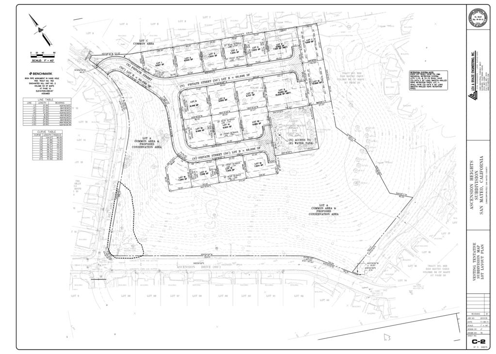
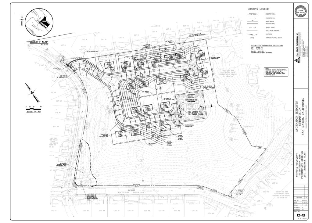
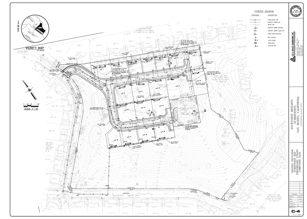
4 Page 1 Lea & Braze Engineering, Inc. Job No INTRODUCTION Ascension Heights Subdivision is a new 19 lot subdivision on a moderately steep slope in San Mateo (Unincorporated). The project is surrounded on two sides by developed streets with curb, gutter and sidewalk and is serviced by a traditional storm drain system. The current storm drain system appears to have been installed in the late 195 s when the current subdivision was constructed. The system starts in various locations throughout the neighborhood. All systems then drain into the main line, which follows Ascension Drive from the intersection of Ascension Drive and Bel Aire Road and then flows downhill to a drop inlet at the intersection of Ascension Drive and Polhemus Road. At this point the runoff flows across Polhemus Road and outfalls into Polhemus Creek. The proposed project includes new private streets with grades up to 2%. is generally directed to an on-site storm drain system. Each individual lot of this project will have its own bio-retention stormwater treatment area and stormwater retention system which will treat and retain runoff from each lot. four additional bio-retention stormwater treatment areas are proposed to treat runoff from the new streets. DRAINAGE NARRATIVE The project has been designed with several permanent Best Management Practice (BMP s) for long term treatment of the runoff. Each lot will have its own individual bio-retention stormwater treatment area meeting the requirements of provision C.3, and its own individual stormwater retention system. from the new roadways will be similarly treated with the use of bio-retention areas. The premise for the design is grade the site to allow runoff from the lots to flow through the bio-retention treatment area prior to entering the stormwater retention system. Once the runoff leaves the individual retention system, it then enters the subdivision main storm drain system and will be directed to the existing off-site storm drain system. The sizing of the treatment areas and retention systems was determined by assuming that each lot will be built out to the full extent of the zoning code which states that the maximum hardscape area is 4% of each lot. C.3 bio-retention sizing for each lot, and the new streets, is calculated using the uniform intensity approach as provided for in the San Mateo Countywide Water Pollution Prevention Program C.3 Stormwater Technical Guidance Handbook by providing a
5 Page 2 Lea & Braze Engineering, Inc. Job No treatment area with no less than 4% of the impervious area to be treated by the bioretention area.. The stormwater retention pipe size and length for each lot are specified in the enclosed calculations. The pipe size and length are specified in the enclosed calculations. Lots 1-1, and will have 3-24 diameter x 3 long retention pipes. Lot 11 will have 3-24 diameter x 4 long retention pipes. This system will retain stormwater runoff in each lot prior to entering the storm drain system. Then, the runoff will be collected in a common main and conveyed to the adjacent existing storm drain system in either Ascension Drive or Bel Aire Road. Please note that the bio-retention stormwater treatment areas and retention systems need to have a regular maintenance schedule to perform properly. It is anticipated that any CC&Rs will require a maintenance agreement. It is recommended that a maintenance agreement be made part of any conditions of approval for the tentative map. The goal of this design is to treat and retain the runoff from the site and release it at predevelopment rates. Our design philosophy is to only have retention on individual lots and not retain the roadway runoff. (We will however treat the roadway runoff in bioretention areas before it is released off the site.) Therefore, each lot retention system has been oversized in order to compensate for the runoff from the roadway. The total predevelopment runoff from the entire project was cfs. The total post development runoff including the roadway was determined to be cfs. The net flow rate difference, which is also the amount of runoff that we are required to retain on-site, is 4.39 cfs. The proposed system of oversized retention pipes on each lot can retain a maximum of 4.48 cfs total. Therefore, the system can retain and meter release the flows below the predevelopment rate of cfs. The calculations within this report demonstrate that each lot has the ability to retain enough runoff such that collectively, all 19 lots aid in releasing runoff at a predevelopment rate to compensate for all new impervious surfaces resulting from the new private streets. Retention is thereby provided for the runoff resulting from the streets. NPDES C.3 COMPLIANCE Two changes occur over the course of this development. First, natural pervious ground cover is converted to impervious areas such as rooftops and roads. Natural soil acts as an absorbent for rainwater and also removes pollutants through purification and filtration. Impervious areas can neither absorb rainwater nor remove pollutants. Due to this increase of impervious area, increase flows and volumes of stormwater will be released from the development which may adversely impact environmentally sensitive areas. Secondly, this development can create new pollution such as oils and trash from the roadway. As rain becomes runoff, it will carry the untreated pollutants over the
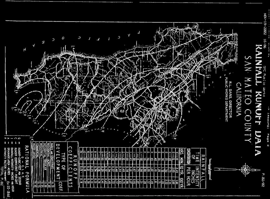
6 Page 3 Lea & Braze Engineering, Inc. Job No impervious area to a storm drain system which leads to a body of water. As a result, the goal of the NPDES Provision C.3 is to release the stormwater at pre-development rates and treat the runoff prior to it leaving the site. In the Ascension Heights Subdivision, great care has been taken to comply with the NPDES Provision C.3. For design and calculation purposes only, each residential lot is assumed to have the maximum of 4% impervious surface area, which leaves 6% of each lot as pervious ground for filtration purposes. Each residential lot will treat runoff from that lot using bio-retention, and store and store the runoff in a series of large diameter retention pipes to meter the stormwater at pre-development rates. Each retention system will be reevaluated for adequacy at the time of construction. Thus, we are proposing to release runoff at pre-development rates and treat all runoff prior to it leaving the project and entering the County storm drain system. ASSUMPTIONS AND METHODOLOGY This section includes data used in calculating the pre-development and postdevelopment runoff volumes, and in calculating the capacity of the existing storm drainage system. References: - Topographic Survey by Lea & Braze Engineering, Inc. - San Mateo County Rainfall Data Map - HydroCAD 9.1 UNIT HYDROGRAPH Definitions Copyright (c) 21 Applied Microcomputer Systems Project Information: Project Location: Ascension Drive at Bel Aire Road San Mateo, California (Unincorporated) APN: , 13, 16, 27, 28, 32, 36 Hydrology Information: Storm Interval: Rainfall Intensity (I): 1 Year Return, 1 min. rainfall intensity 2.21 in/hour (Per San Mateo County Rainfall Data Map) Initial Intensity (1 Minutes) In performing the hydrological calculations, the Rational Method (Q=C*I*A) was used, as specified in the San Mateo County, Guidelines for Drainage Review. A 1- year storm event interval was used in the calculations. Per instructions in the guideline
7 Page 4 Lea & Braze Engineering, Inc. Job No and confirmation with Pete Bentley, engineer with the County, the project is outside of any floodplain. The size, slope, material type and location of the existing system was done in combination with a field survey which located and verified As-built conditions of the system and the original improvement plans 1 for the system. The method used for determining C values for areas that include the large areas of undeveloped land that comprise the parcel was determined by a weighted average method of calculating the percentage of each type of surface, whether residential, asphalt streets or open space. This was computed automatically for each of the areas in HydroCAD. The of Concentration (Tc) was determined by assuming an initial Tc at the uppermost inlet of ten minutes. Starting with the initial Tc and adding the pipe flow time, we then computed the actual Tc at each structure. Since multiple storm drain systems connected to the main system, the overall area and the longest Tc value was used for each structure. Thus some structures jump dramatically in time from the upstream inlet because the runoff took longer to get to this inlet via the branch system that connected to it. The values for the frictional coefficient, n were determined by both manufacturers specifications for the new Corrugated HDPE smooth wall pipe and a good condition for the existing reinforced concrete pipe. Pipe n HANCOR Hi-Q PIPE 2.11 Reinforced Concrete Pipe (good condition) 3.13 Hydraulic information was also omitted in this report. Since the slope of the majority of the pipes is in excess of 1% and the new and existing systems are located in a very steep environment, there is negligible chance of having any hydraulic problems. In most instances the hydraulic grade line will simply be the actual water level of the runoff in the pipe section itself. Pete Bentley, engineer for the County of San Mateo, agreed and said that the County would not require any hydraulic calculations. RESULTS/RECOMMENDATIONS 1 Improvement Plans Enchanted Hills Unit No. 2, dated November HANCOR Hi-Q PIPE SPECIFICATION, 3 Drainage Manual, County of Santa Clara, Department of Public Works.
8 Page 5 Lea & Braze Engineering, Inc. Job No Detailed hydrology calculations for both the existing and proposed systems are shown in Exhibit A. The calculations take into account all the information shown in the references sheet, the assumptions and methodology section of this report and good engineering judgment. EXISTING SYSTEM The results of the calculations shown in Exhibit A.1 show that the existing system is able to handle runoff with two pipe run exceptions. Pipe P-6 as shown on the existing hydrology base map is a 15 RCP sloped at 2%. This is primarily due to its flat slope. The outfall pipe, P-12 that crosses Polhemus Road is also over capacity. This is a 3 RCP sloped at 1.3%. This too has capacity problems due to its flat slope. All other pipes exceed the capacity requirements. PROPOSED SYSTEM The proposed system is specifically designed to handle a 1 year event. As the calculations shown on Exhibit A.2 show both Line N and Line S have been designed to fully handle any anticipated runoff caused by a 1 year event. HOW THE PROPOSED SYSTEM WILL IMPACT THE EXISTING SYSTEM The proposed design will have little impact on the existing system. Since the proposed system has a great deal of capacity to it and a long time of concentration, the runoff will be contained in the pipe for some time before it has a chance to severely impact the existing system. The actual system flow is increased with the additional impervious surfaces, however the majority of the pipes in the system are able to handle the additional runoff with no adverse effects. As with the existing system, however, the added runoff has an adverse effect on the same two pipes that posed problems on the existing system. Should the rainfall from a severe storm exceed that of a 1-year event, or the lines or inlets get clogged, the water does have an overland release via the public streets. Due to the extreme slope of the existing streets, any runoff that is not intercepted by the existing storm drain system will simply drain down Ascension and flow over Polhemus Road and into the creek. Thus it is anticipated that none of the existing houses or neighboring hillsides in the neighborhood would be affected by any flooding as a result of additional runoff imposed by this development. The proposed on-site system does have some low spots to it in the new public street that would prevent overland release via the streets. In this case the pipes have been intentionally oversized to handle as much capacity as possible, even in the event of some blockage.
9 Page 6 Lea & Braze Engineering, Inc. Job No The analysis incorporated in this report has shown that the existing system can handle the anticipated additional runoff from the proposed development, except for two specific pipes. It is recommended that these pipes be redesigned and upsized to increase their capacity, both for the existing condition and the proposed development. In the case of pipe P-C7, in which a 15 RCP flowing at 2.% is crossing Ascension Drive at Enchanted Way, we recommend a new 21 RCP replace the existing pipe. Since the upstream and downstream pipe are of adequate size, it is more reasonable to simply replace the pipe at the same invert locations as is currently in place. In the case of pipe P-C13, in which a 3 RCP flows at 1.3%, it is feasible to both increase the size of the pipe as well as increase the slope. The upstream invert of this outgoing pipe is several feet lower than the incoming pipe invert, thus the invert can be raised and not affect the upstream pipe. We recommend replacing the existing 3 RCP with a 36 RCP sloped at 2%. In both cases, the recommendations will allow the entire system to handle the design storm event with a factor of safety built into it. The calculations for the above recommendations are shown in Exhibit A.2. Using HydroCAD software, we were able to preliminarily size retention systems for each of the proposed lots. The retention systems were oversized to account for the extra runoff contributed by the new roadway, since logistically retention specifically for the roadway would very difficult to design and locate on the steep site. The designed retention systems achieve the desired goal of keeping the post-construction runoff rates at or below the pre-construction runoff rates. Lots 1, 6 Retention System: Based on our calculations assuming a 4% impervious surface build out, preconstruction flow is.2 cfs. The post-construction flow is.37 cfs. The net increase due to the construction is.17 cfs. The proposed detention system retains and meters release of.11 cfs for a 1 year storm. This proposed storm study is for a 1 minute time of concentration. The proposed retention system consists of (3) 24 diameter x 3 long solid wall HDPE pipes. The primary outlet pipe is a 2 PVC with an 8 secondary emergency overflow pipe. The secondary outlet will not be used for drainage but would be utilized only in an emergency situation. The system slows down the incoming flow and meters the outflow over a 1 (or more) hour time period. This amount of runoff will be held in the retention pipes. Lots 2, 7 Retention System:
10 Page 7 Lea & Braze Engineering, Inc. Job No Based on our calculations assuming a 4% impervious surface build out, preconstruction flow is.18 cfs. The post-construction flow is.33 cfs. The net increase due to the construction is.15 cfs. The proposed detention system retains and meters release of.1 cfs for a 1 year storm. This proposed storm study is for a 1 minute time of concentration. The proposed retention system consists of (3) 24 diameter x 3 long solid wall HDPE pipes. The primary outlet pipe is a 2 PVC with an 8 secondary emergency overflow pipe. The secondary outlet will not be used for drainage but would be utilized only in an emergency situation. The system slows down the incoming flow and meters the outflow over a 1 (or more) hour time period. This amount of runoff will be held in the retention pipes. Lots 3-5, Retention System: Based on our calculations assuming a 4% impervious surface build out, preconstruction flow is.15 cfs. The post-construction flow is.28 cfs. The net increase due to the construction is.13 cfs. The proposed detention system retains and meters release of.9 cfs for a 1 year storm. This proposed storm study is for a 1 minute time of concentration. The proposed retention system consists of (3) 24 diameter x 3 long solid wall HDPE pipes. The primary outlet pipe is a 2 PVC with an 8 secondary emergency overflow pipe. The secondary outlet will not be used for drainage but would be utilized only in an emergency situation. The system slows down the incoming flow and meters the outflow over a 1 (or more) hour time period. This amount of runoff will be held in the retention pipes. Lots 8, 9, 13, 14 Retention System: Based on our calculations assuming a 4% impervious surface build out, preconstruction flow is.19 cfs. The post-construction flow is.35 cfs. The net increase due to the construction is.16 cfs. The proposed detention system retains and meters release of.1 cfs for a 1 year storm. This proposed storm study is for a 1 minute time of concentration. The proposed retention system consists of (3) 24 diameter x 3 long solid wall HDPE pipes. The primary outlet pipe is a 2 PVC with an 8 secondary emergency overflow pipe. The secondary outlet will not be used for drainage but would be utilized only in an emergency situation. The system slows down the incoming flow and meters the outflow over a 1 (or more) hour time period. This amount of runoff will be held in the retention pipes. Lot 1 Retention System: Based on our calculations assuming a 4% impervious surface build out, preconstruction flow is.2 cfs. The post-construction flow is.36 cfs. The net increase due to the construction is.16 cfs. The proposed detention system retains and meters release of.1 cfs for a 1 year storm. This proposed storm study is for a 1 minute time
11 Page 8 Lea & Braze Engineering, Inc. Job No of concentration. The proposed retention system consists of (3) 24 diameter x 3 long solid wall HDPE pipes. The primary outlet pipe is a 2 PVC with an 8 secondary emergency overflow pipe. The secondary outlet will not be used for drainage but would be utilized only in an emergency situation. The system slows down the incoming flow and meters the outflow over a 1 (or more) hour time period. This amount of runoff will be held in the retention pipes. Lot 11 Retention System: Based on our calculations assuming a 4% impervious surface build out, preconstruction flow is.28 cfs. The post-construction flow is.52 cfs. The net increase due to the construction is.24 cfs. The proposed detention system retains and meters release of.12 cfs for a 1 year storm. This proposed storm study is for a 1 minute time of concentration. The proposed retention system consists of (3) 24 diameter x 4 long solid wall HDPE pipes. The primary outlet pipe is a 2 PVC with an 8 secondary emergency overflow pipe. The secondary outlet will not be used for drainage but would be utilized only in an emergency situation. The system slows down the incoming flow and meters the outflow over a 1 (or more) hour time period. This amount of runoff will be held in the retention pipes. Lot 12 Retention System: Based on our calculations assuming a 4% impervious surface build out, preconstruction flow is.22 cfs. The post-construction flow is.4 cfs. The net increase due to the construction is.18 cfs. The proposed detention system retains and meters release.11 cfs for a 1 year storm. This proposed storm study is for a 1 minute time of concentration. The proposed retention system consists of (3) 24 diameter x 3 long solid wall HDPE pipes. The primary outlet pipe is a 2 PVC with an 8 secondary emergency overflow pipe. The secondary outlet will not be used for drainage but would be utilized only in an emergency situation. The system slows down the incoming flow and meters the outflow over a 1 (or more) hour time period. This amount of runoff will be held in the retention pipes. Lot 15 Retention System: Based on our calculations assuming a 4% impervious surface build out, preconstruction flow is.17 cfs. The post-construction flow is.32 cfs. The net increase due to the construction is.15 cfs. The proposed detention system retains and meters release of.1 cfs for a 1 year storm. This proposed storm study is for a 1 minute time of concentration. The proposed retention system consists of (3) 24 diameter x 3 long solid wall HDPE pipes. The primary outlet pipe is a 2 PVC with an 8 secondary emergency overflow pipe. The secondary outlet will not be used for drainage but would be utilized only in an emergency situation. The system slows down the incoming flow
12 Page 9 Lea & Braze Engineering, Inc. Job No and meters the outflow over a 1 (or more) hour time period. This amount of runoff will be held in the retention pipes.
13 Appendix A
14 EXISTING SITE PRE Page 1 Subcatchment 1S: EXISTING SITE TOTAL PRE Hydrograph Flow cfs san mateo 1-Year-.9 Duration=1 min, Inten=2.21 in/hr Area=62,562 sf Volume=.174 af Depth=.15" Tc=1. min C=
15 EXISTING SITE PRE Page 2 Hydrograph for Subcatchment 1S: EXISTING SITE TOTAL PRE
16 Appendix B
17 LOT 1 Page 1 Subcatchment 1S: Lot 1 Post Hydrograph Flow cfs san mateo 1-Year-.9 Duration=1 min, Inten=2.21 in/hr Area=9,827 sf Volume=.5 af Depth=.27" Tc=1. min C=
18 LOT 1 Page 2 Hydrograph for Subcatchment 1S: Lot 1 Post
19 LOT 1 Page 3 Subcatchment 6S: Lot 1 Pre Hydrograph Flow cfs san mateo 1-Year-.9 Duration=1 min, Inten=2.21 in/hr Area=9,827 sf Volume=.3 af Depth=.15" Tc=1. min C=
20 LOT 1 Page 4 Hydrograph for Subcatchment 6S: Lot 1 Pre
21 LOT 1 Page 5 Pond 5P: detention basin Hydrograph Flow cfs.37 cfs.11 cfs.11 cfs Inflow Area=.226 ac Peak Elev=626.' Storage=.3 af Inflow Outflow Primary Secondary
22 LOT 1 Page 6 Hydrograph for Pond 5P: detention basin Inflow Storage (acre-feet) Elevation (feet) Outflow Primary Secondary
23 LOT 2 Page 1 Subcatchment 1S: Lots 2 Post Hydrograph Flow cfs san mateo 1-Year-.9 Duration=1 min, Inten=2.21 in/hr Area=9, sf Volume=.5 af Depth=.27" Tc=1. min C=
24 LOT 2 Page 2 Hydrograph for Subcatchment 1S: Lots 2 Post
25 LOT 2 Page 3 Subcatchment 6S: Lots 2 Pre Hydrograph Flow cfs san mateo 1-Year-.9 Duration=1 min, Inten=2.21 in/hr Area=9, sf Volume=.3 af Depth=.15" Tc=1. min C=
26 LOT 2 Page 4 Hydrograph for Subcatchment 6S: Lots 2 Pre
27 LOT 2 Page 5 Pond 5P: detention basin Hydrograph Flow cfs.33 cfs.1 cfs.1 cfs Inflow Area=.27 ac Peak Elev=625.92' Storage=.3 af Inflow Outflow Primary Secondary
28 LOT 2 Page 6 Hydrograph for Pond 5P: detention basin Inflow Storage (acre-feet) Elevation (feet) Outflow Primary Secondary
29 LOT 3,4,5,18 Page 1 Subcatchment 1S: Lots 3,4,5,18 Post Hydrograph Flow cfs san mateo 1-Year-.9 Duration=1 min, Inten=2.21 in/hr Area=7,5 sf Volume=.4 af Depth=.27" Tc=1. min C=
30 LOT 3,4,5,18 Page 2 Hydrograph for Subcatchment 1S: Lots 3,4,5,18 Post
31 LOT 3,4,5,18 Page 3 Subcatchment 6S: Lots 3,4,5,18 Pre Hydrograph Flow cfs san mateo 1-Year-.9 Duration=1 min, Inten=2.21 in/hr Area=7,5 sf Volume=.2 af Depth=.15" Tc=1. min C=
32 LOT 3,4,5,18 Page 4 Hydrograph for Subcatchment 6S: Lots 3,4,5,18 Pre
33 LOT 3,4,5,18 Page 5 Pond 5P: detention basin Hydrograph cfs Inflow Area=.172 ac Peak Elev=625.77' Storage=.2 af Inflow Outflow Primary Secondary.22.2 Flow cfs.9 cfs cfs
34 LOT 3,4,5,18 Page 6 Hydrograph for Pond 5P: detention basin Inflow Storage (acre-feet) Elevation (feet) Outflow Primary Secondary
35 LOT 6 Page 1 Subcatchment 1S: Lots 6 Post Hydrograph Flow cfs san mateo 1-Year-.9 Duration=1 min, Inten=2.21 in/hr Area=9,964 sf Volume=.5 af Depth=.27" Tc=1. min C=
36 LOT 6 Page 2 Hydrograph for Subcatchment 1S: Lots 6 Post
37 LOT 6 Page 3 Subcatchment 6S: Lots 6 Pre Hydrograph Flow cfs san mateo 1-Year-.9 Duration=1 min, Inten=2.21 in/hr Area=9,964 sf Volume=.3 af Depth=.15" Tc=1. min C=
38 LOT 6 Page 4 Hydrograph for Subcatchment 6S: Lots 6 Pre
39 LOT 6 Page 5 Pond 5P: detention basin Hydrograph Flow cfs.37 cfs.11 cfs.11 cfs Inflow Area=.229 ac Peak Elev=626.2' Storage=.3 af Inflow Outflow Primary Secondary
40 LOT 6 Page 6 Hydrograph for Pond 5P: detention basin Inflow Storage (acre-feet) Elevation (feet) Outflow Primary Secondary
41 LOT 7 Page 1 Subcatchment 1S: Lots 7 Post Hydrograph Flow cfs san mateo 1-Year-.9 Duration=1 min, Inten=2.21 in/hr Area=8,912 sf Volume=.5 af Depth=.27" Tc=1. min C=
42 LOT 7 Page 2 Hydrograph for Subcatchment 1S: Lots 7 Post
43 LOT 7 Page 3 Subcatchment 6S: Lots 7 Pre Hydrograph Flow cfs san mateo 1-Year-.9 Duration=1 min, Inten=2.21 in/hr Area=8,912 sf Volume=.3 af Depth=.15" Tc=1. min C=
44 LOT 7 Page 4 Hydrograph for Subcatchment 6S: Lots 7 Pre
45 LOT 7 Page 5 Pond 5P: detention basin Hydrograph Flow cfs.33 cfs.1 cfs.1 cfs Inflow Area=.25 ac Peak Elev=625.91' Storage=.3 af Inflow Outflow Primary Secondary
46 LOT 7 Page 6 Hydrograph for Pond 5P: detention basin Inflow Storage (acre-feet) Elevation (feet) Outflow Primary Secondary
47 LOT 8,13 Page 1 Subcatchment 1S: Lot 8,13 Post Hydrograph Flow cfs san mateo 1-Year-.9 Duration=1 min, Inten=2.21 in/hr Area=9,466 sf Volume=.5 af Depth=.27" Tc=1. min C=
48 LOT 8,13 Page 2 Hydrograph for Subcatchment 1S: Lot 8,13 Post
49 LOT 8,13 Page 3 Subcatchment 6S: Lot 8,13 Pre Hydrograph Flow cfs san mateo 1-Year-.9 Duration=1 min, Inten=2.21 in/hr Area=9,466 sf Volume=.3 af Depth=.15" Tc=1. min C=
50 LOT 8,13 Page 4 Hydrograph for Subcatchment 6S: Lot 8,13 Pre
51 LOT 8,13 Page 5 Pond 5P: detention basin Hydrograph Flow cfs.35 cfs.1 cfs.1 cfs Inflow Area=.217 ac Peak Elev=625.97' Storage=.3 af Inflow Outflow Primary Secondary
52 LOT 8,13 Page 6 Hydrograph for Pond 5P: detention basin Inflow Storage (acre-feet) Elevation (feet) Outflow Primary Secondary
53 LOT 9,14 Page 1 Subcatchment 1S: Lots 9,14 Post Hydrograph Flow cfs san mateo 1-Year-.9 Duration=1 min, Inten=2.21 in/hr Area=9,5 sf Volume=.5 af Depth=.27" Tc=1. min C=
54 LOT 9,14 Page 2 Hydrograph for Subcatchment 1S: Lots 9,14 Post
55 LOT 9,14 Page 3 Subcatchment 6S: Lots 9,14 Pre Hydrograph Flow cfs san mateo 1-Year-.9 Duration=1 min, Inten=2.21 in/hr Area=9,5 sf Volume=.3 af Depth=.15" Tc=1. min C=
56 LOT 9,14 Page 4 Hydrograph for Subcatchment 6S: Lots 9,14 Pre
57 LOT 9,14 Page 5 Pond 5P: detention basin Hydrograph Flow cfs.35 cfs.1 cfs.1 cfs Inflow Area=.218 ac Peak Elev=625.97' Storage=.3 af Inflow Outflow Primary Secondary
58 LOT 9,14 Page 6 Hydrograph for Pond 5P: detention basin Inflow Storage (acre-feet) Elevation (feet) Outflow Primary Secondary
59 LOT 1 Page 1 Subcatchment 1S: Lots 1 Post Hydrograph Flow cfs san mateo 1-Year-.9 Duration=1 min, Inten=2.21 in/hr Area=9,77 sf Volume=.5 af Depth=.27" Tc=1. min C=
60 LOT 1 Page 2 Hydrograph for Subcatchment 1S: Lots 1 Post
61 LOT 1 Page 3 Subcatchment 6S: Lots 1 Pre Hydrograph Flow cfs san mateo 1-Year-.9 Duration=1 min, Inten=2.21 in/hr Area=9,77 sf Volume=.3 af Depth=.15" Tc=1. min C=
62 LOT 1 Page 4 Hydrograph for Subcatchment 6S: Lots 1 Pre
63 LOT 1 Page 5 Pond 5P: detention basin Hydrograph Flow cfs.36 cfs.1 cfs.1 cfs Inflow Area=.223 ac Peak Elev=625.99' Storage=.3 af Inflow Outflow Primary Secondary
64 LOT 1 Page 6 Hydrograph for Pond 5P: detention basin Inflow Storage (acre-feet) Elevation (feet) Outflow Primary Secondary
65 LOT 11 Page 1 Subcatchment 1S: Lots 11 Post Hydrograph Flow cfs san mateo 1-Year-.9 Duration=1 min, Inten=2.21 in/hr Area=15,982 sf Volume=.8 af Depth=.27" Tc=1. min C=
66 LOT 11 Page 2 Hydrograph for Subcatchment 1S: Lots 11 Post
67 LOT 11 Page 3 Subcatchment 6S: Lots 11 Pre Hydrograph Flow cfs san mateo 1-Year-.9 Duration=1 min, Inten=2.21 in/hr Area=15,982 sf Volume=.5 af Depth=.15" Tc=1. min C=
68 LOT 11 Page 4 Hydrograph for Subcatchment 6S: Lots 11 Pre
69 LOT 11 Page 5 Pond 5P: detention basin Hydrograph cfs Inflow Area=.367 ac Peak Elev=626.34' Storage=.6 af Inflow Outflow Primary Secondary.45 Flow cfs.12 cfs.1.5. cfs
70 LOT 11 Page 6 Hydrograph for Pond 5P: detention basin Inflow Storage (acre-feet) Elevation (feet) Outflow Primary Secondary
71 LOT 12 Page 1 Subcatchment 1S: Lot 12 Post Hydrograph Flow cfs san mateo 1-Year-.9 Duration=1 min, Inten=2.21 in/hr Area=1,696 sf Volume=.6 af Depth=.27" Tc=1. min C=
72 LOT 12 Page 2 Hydrograph for Subcatchment 1S: Lot 12 Post
73 LOT 12 Page 3 Subcatchment 6S: Lot 12 Pre Hydrograph Flow cfs san mateo 1-Year-.9 Duration=1 min, Inten=2.21 in/hr Area=1,696 sf Volume=.3 af Depth=.15" Tc=1. min C=
74 LOT 12 Page 4 Hydrograph for Subcatchment 6S: Lot 12 Pre
75 LOT 12 Page 5 Pond 5P: detention basin Hydrograph Flow cfs.4 cfs.11 cfs.11 cfs Inflow Area=.246 ac Peak Elev=626.9' Storage=.4 af Inflow Outflow Primary Secondary
76 LOT 12 Page 6 Hydrograph for Pond 5P: detention basin Inflow Storage (acre-feet) Elevation (feet) Outflow Primary Secondary
77 LOT 15 Page 1 Subcatchment 1S: Lot 15 Post Hydrograph Flow cfs san mateo 1-Year-.9 Duration=1 min, Inten=2.21 in/hr Area=8,669 sf Volume=.5 af Depth=.27" Tc=1. min C=
78 LOT 15 Page 2 Hydrograph for Subcatchment 1S: Lot 15 Post
79 LOT 15 Page 3 Subcatchment 6S: Lot 15 Pre Hydrograph Flow cfs san mateo 1-Year-.9 Duration=1 min, Inten=2.21 in/hr Area=8,669 sf Volume=.2 af Depth=.15" Tc=1. min C=
80 LOT 15 Page 4 Hydrograph for Subcatchment 6S: Lot 15 Pre
81 LOT 15 Page 5 Pond 5P: detention basin Hydrograph Flow cfs.32 cfs.1 cfs.1 cfs Inflow Area=.199 ac Peak Elev=625.89' Storage=.3 af Inflow Outflow Primary Secondary
82 LOT 15 Page 6 Hydrograph for Pond 5P: detention basin Inflow Storage (acre-feet) Elevation (feet) Outflow Primary Secondary
83 LOT 16 Page 1 Subcatchment 1S: Lot 16 Post Hydrograph Flow cfs san mateo 1-Year-.9 Duration=1 min, Inten=2.21 in/hr Area=7,563 sf Volume=.4 af Depth=.27" Tc=1. min C=
84 LOT 16 Page 2 Hydrograph for Subcatchment 1S: Lot 16 Post
85 LOT 16 Page 3 Subcatchment 6S: Lot 16 Pre Hydrograph Flow cfs san mateo 1-Year-.9 Duration=1 min, Inten=2.21 in/hr Area=7,563 sf Volume=.2 af Depth=.15" Tc=1. min C=
86 LOT 16 Page 4 Hydrograph for Subcatchment 6S: Lot 16 Pre
87 LOT 16 Page 5 Pond 5P: detention basin Hydrograph cfs Inflow Area=.174 ac Peak Elev=625.77' Storage=.2 af Inflow Outflow Primary Secondary.22.2 Flow cfs.9 cfs cfs
88 LOT 16 Page 6 Hydrograph for Pond 5P: detention basin Inflow Storage (acre-feet) Elevation (feet) Outflow Primary Secondary
89 LOT 17 Page 1 Subcatchment 1S: Lot 17 Post Hydrograph Flow cfs san mateo 1-Year-.9 Duration=1 min, Inten=2.21 in/hr Area=7,538 sf Volume=.4 af Depth=.27" Tc=1. min C=
90 LOT 17 Page 2 Hydrograph for Subcatchment 1S: Lot 17 Post
91 LOT 17 Page 3 Subcatchment 7S: Lot 17 Pre Hydrograph Flow cfs san mateo 1-Year-.9 Duration=1 min, Inten=2.21 in/hr Area=7,538 sf Volume=.2 af Depth=.15" Tc=1. min C=
92 LOT 17 Page 4 Hydrograph for Subcatchment 7S: Lot 17 Pre
93 LOT 17 Page 5 Pond 5P: detention basin Hydrograph cfs Inflow Area=.173 ac Peak Elev=625.77' Storage=.2 af Inflow Outflow Primary Secondary.22.2 Flow cfs.9 cfs cfs
94 LOT 17 Page 6 Hydrograph for Pond 5P: detention basin Inflow Storage (acre-feet) Elevation (feet) Outflow Primary Secondary
95 LOT 19 Page 1 Subcatchment 7S: Lot 19 Pre Hydrograph Flow cfs san mateo 1-Year-.9 Duration=1 min, Inten=2.21 in/hr Area=7,54 sf Volume=.2 af Depth=.15" Tc=1. min C=
96 LOT 19 Page 2 Hydrograph for Subcatchment 7S: Lot 19 Pre
97 LOT 19 Page 3 Subcatchment 8S: Lot 19 Post Hydrograph Flow cfs san mateo 1-Year-.9 Duration=1 min, Inten=2.21 in/hr Area=7,54 sf Volume=.4 af Depth=.27" Tc=1. min C=
98 LOT 19 Page 4 Hydrograph for Subcatchment 8S: Lot 19 Post
99 LOT 19 Page 5 Pond 5P: detention basin Hydrograph cfs Inflow Area=.172 ac Peak Elev=625.77' Storage=.2 af Inflow Outflow Primary Secondary.22.2 Flow cfs.9 cfs cfs
100 LOT 19 Page 6 Hydrograph for Pond 5P: detention basin Inflow Storage (acre-feet) Elevation (feet) Outflow Primary Secondary
101 Appendix C
102 Storm Drain Design by Rational Formula - County of San Mateo Lea & Braze Job # Ascension Heights Subdivision Ascension Dr and Bel Aire Rd, San Mateo 1 YEAR STORM County - Line "C" (Existing) Exhibit A Label Description Tc (min) Local Intensity (in/hr) Area Designation Area (acres) C System Contributing flow Total System Flow Pipe Size (inches) Pipe Type Manning's "n" Pipe Length (ft) Pipe Slope (ft/ft) Average Velocity (ft/s) Pipe Flow (min) I-1 (E) COUNTY INLET AREA C P RCP % 'NO I-2 (E) COUNTY INLET AREA C AREA C P RCP % 'NO I-3 (E) COUNTY INLET AREA C AREA C P RCP % 'NO SDMH-1 (E) COUNTY MANHOLE P RCP % 'NO I-4 (E) COUNTY INLET AREA C P RCP % 'NO I-5 (E) COUNTY INLET AREA C P RCP % 'YES I-6 (E) COUNTY INLET AREA C AREA C P RCP % 'NO I-7 (E) COUNTY INLET AREA C P RCP % 'NO I-8 (E) COUNTY INLET AREA C P RCP % 'NO I-9 (E) COUNTY INLET AREA C P RCP % 'NO I-1 P-11 (E) COUNTY INLET AREA C RCP % 'NO I-11 (E) COUNTY INLET AREA C P RCP % 'YES OUTLET POLHEMUS CREEK Pipe Capacity Exceeds Capacity
103
104 Storm Drain Design by Rational Formula - County of San Mateo Ascension Heights Subdivision Ascension Dr and Bel Aire Rd, San Mateo 1 YEAR STORM North Side - Line "N" Exhibit A.2 Lea & Braze Job # Label Description Tc (min) Local Intensity (in/hr) Area Designation Area (sf) Area (acres) C System Contributing flow Total System Flow Pipe Size (inches) Pipe Type Manning's "n" Pipe Length (ft) Pipe Slope (ft/ft) Average Velocity (ft/s) Pipe Flow (min) CB-N1 (N) COUNTY INLET AREA N P-N HDPE % 'NO SDMH-N1 (N) COUNTY MANHOLE AREA N AREA N-9a P-N HDPE % 'NO SDMH-N2 (N) COUNTY MANHOLE AREA N P-N HDPE % 'NO SDMH-N3 (N) COUNTY MANHOLE P-N HDPE % 'NO SDMH-N4 (N) COUNTY MANHOLE AREA N AREA N AREA N AREA N AREA N AREA N AREA N P-N HDPE % 'NO CB-N2 (N) COUNTY INLET AREA N AREA N AREA N AREA N P-N HDPE % 'NO CB-N7 (N) COUNTY INLET AREA N P-N HDPE % 'NO CB-N3 (N) COUNTY INLET AREA N P-N HDPE % 'NO SDMH-N5 (N) COUNTY MANHOLE P-N HDPE % 'NO CB-N4 (N) COUNTY INLET AREA N P-N HDPE % 'NO CB-N5 (N) COUNTY INLET AREA N P-N HDPE % 'NO CB-N6 (N) COUNTY INLET AREA N AREA N AREA N AREA N-15a AREA N P-N HDPE % 'NO CB-N8 (N) COUNTY INLET AREA N P-N HDPE % 'NO SDMH-N6 (N) COUNTY MANHOLE P-N HDPE % 'NO SDMH-N7 (N) COUNTY MANHOLE P-N HDPE % 'NO SDMH-N8 (N) COUNTY MANHOLE P-N HDPE % 'NO SDMH-N9 (N) COUNTY MANHOLE AREA N P-N HDPE % 'NO SDMH-N1 (N) COUNTY MANHOLE Lea Braze Engineering, Inc. Page 1 Pipe Capacity Exceeds Capacity
105 Label Description Tc (min) Local Intensity (in/hr) Area Designation Area (sf) Area (acres) C System Contributing flow Total System Flow Pipe Size (inches) Pipe Type Manning's "n" Pipe Length (ft) Pipe Slope (ft/ft) Average Velocity (ft/s) Pipe Flow (min) P-N HDPE % 'NO SDMH-N11 (N) COUNTY MANHOLE P-N HDPE % 'NO SDMH-C2 (N) COUNTY MANHOLE Pipe Capacity Exceeds Capacity Lea Braze Engineering, Inc. Page 2
106 Storm Drain Design by Rational Formula - County of San Mateo Lea & Braze Job # Ascension Heights Subdivision Ascension Dr and Bel Aire Rd, San Mateo 1 YEAR STORM South Side - Line "S" Exhibit A Label Description Tc (min) Local Intensity (in/hr) Area Designation Area (sf) Area (acres) C System Contributing flow Total System Flow Pipe Size (inches) Pipe Type Manning's "n" Pipe Length (ft) Pipe Slope (ft/ft) Average Velocity (ft/s) Pipe Flow (min) CB-S1 (N) V-24 CATCH BASIN AREA S AREA S-1a P-S HDPE % 'NO CB-S2 (N) V-24 CATCH BASIN AREA S P-S HDPE % 'NO CB-S3 (N) V-24 CATCH BASIN AREA S P-S HDPE % 'NO CB-S4 (N) V-24 CATCH BASIN AREA S P-S HDPE % 'NO SDMH-S1 (N) COUNTY MANHOLE P-S HDPE % 'NO SDMH-S2 (N) COUNTY MANHOLE P-S HDPE % 'NO SDMH-S3 (N) COUNTY MANHOLE P-S HDPE % 'NO SDMH-C2 (N) COUNTY MANHOLE Pipe Capacity Exceeds Capacity
107 Storm Drain Design by Rational Formula - County of San Mateo Lea & Braze Job # Ascension Heights Subdivision Ascension Dr and Bel Aire Rd, San Mateo 1 YEAR STORM County - Line "C" Exhibit A Label Description Tc (min) Local Intensity (in/hr) Area Designation Area (acres) C System Contributing flow Total System Flow Pipe Size (inches) Pipe Type Manning's "n" Pipe Length (ft) Pipe Slope (ft/ft) Average Velocity (ft/s) Pipe Flow (min) I-C1 (E) COUNTY INLET AREA C P-C RCP % 'NO I-C2 (E) COUNTY INLET AREA C AREA C P-C RCP % 'NO I-C3 (E) COUNTY INLET AREA C AREA C P-C RCP % 'NO SDMH-C1 (E) COUNTY MANHOLE P-C RCP % 'NO SDMH-C2 (N) COUNTY MANHOLE NORTH 5.6 SDMH-C2 (N) COUNTY MANHOLE SOUTH.38 P-C RCP % 'NO I-C4 (E) COUNTY INLET AREA C P-C RCP % 'NO I-C5 (E) COUNTY INLET AREA C P-C RCP % 'NO I-C6 (E) COUNTY INLET AREA C AREA C P-C RCP % 'NO I-C7 (E) COUNTY INLET AREA C P-C RCP % 'NO I-C8 (E) COUNTY INLET AREA C P-C RCP % 'NO I-C9 (E) COUNTY INLET AREA C P-C RCP % 'NO I-C1 P-C12 (E) COUNTY INLET AREA C RCP % 'NO I-C11 (E) COUNTY INLET AREA C P-C RCP % 'NO OUTLET POLHEMUS CREEK Pipe Capacity Exceeds Capacity
108
109
110 Appendix D
111
112
113
114
115
116 Appendix E
117
San Francisco State University Site 1 Vegetated Infiltration Basin Monitoring Report: Rainy Seasons and
 San Francisco State University Site 1 Vegetated Infiltration Basin Monitoring Report: Rainy Seasons 2011-12 and 2012-13 Project Overview San Francisco State University (SFSU) has implemented several green
PRELIMINARY DRAINAGE STUDY
 PRELIMINARY DRAINAGE STUDY For 34 th & J Residences 3402 J St. San Diego, CA 92102 A.P.N 545-250-08 Prepared By: Kenneth J. Discenza, P.E. Site Design Associates, Inc. 1016 Broadway, Suite A El Cajon,
PART V - STORM DRAIN DESIGN CRITERIA
 PART V - STORM DRAIN DESIGN CRITERIA A. Hydrology Studies and Hydraulic Analyses 1. Drainage area master plans and calculations are to be submitted with all subdivision improvement plans, permit improvement
PART V - STORM DRAIN DESIGN CRITERIA
 PART V - STORM DRAIN DESIGN CRITERIA A. Hydrology Studies and Hydraulic Analyses 1. Drainage area master plans and calculations are to be submitted with all subdivision improvement plans, permit improvement
Appendix J: The Project Stormwater Control Plan by Lea & Braze Engineering, Inc.
 Appendix J: The Project Stormwater Control Plan by Lea & Braze Engineering, Inc. STORMWATER CONTROL PLAN 23 LOT SUBDIVISION ON PROCTOR ROAD CASTRO VALLEY, CALIFORNIA Owner/Developer: Hue Tran 4584 Ewing
Hydrology Study. For Bella Terrazza Portion of Lot 1, Block 39, Subdivision of S Tract, Rancho El Cajon El Cajon, CA 92021
 Hydrology Study For Bella Terrazza Portion of Lot 1, Block 39, Subdivision of S Tract, Rancho El Cajon El Cajon, CA 92021 Prepared for Daryl Priest - Priest Development Corporation 124 West Main Street,
Hydrologic Study Report for Single Lot Detention Basin Analysis
 Hydrologic Study Report for Single Lot Detention Basin Analysis Prepared for: City of Vista, California August 18, 2006 Tory R. Walker, R.C.E. 45005 President W.O. 116-01 01/23/2007 Table of Contents Page
APPENDIX J-3. Orcem Stormwater Management and Treatment Facilities Design Summary
 APPENDIX J-3 Orcem Stormwater Management and Treatment Facilities Design Summary Stormwater Management & Treatment Facilities Design Summary INTRODUCTION KPFF Consulting Engineers has compiled this report
Dawson County Public Works 25 Justice Way, Suite 2232, Dawsonville, GA (706) x 42228
 x 42228") Dawson County Public Works 25 Justice Way, Suite 2232, Dawsonville, GA 30534 (706) 344-3500 x 42228 DAWSON COUNTY STORM WATER REVIEW CHECKLIST Project Name: Property Address: Engineer: Fax #/Email: Date:
Dawson County Public Works 25 Justice Way, Suite 2232, Dawsonville, GA 30534 (706) 344-3500 x 42228 DAWSON COUNTY STORM WATER REVIEW CHECKLIST Project Name: Property Address: Engineer: Fax #/Email: Date:
Municipal Stormwater Ordinances Summary Table
 APPENDIX F Municipal Ordinances Summary Table Municipality Abington Bryn Athyn Borough Hatboro Borough Ordinance, SALDO Runoff equals pre post Erosion Sediment Control Water Quality Requirements Any which
Preliminary Drainage Analysis
 Preliminary Drainage Analysis Tanimura and Antle Employee Housing Town of Spreckels County of Monterey, California LIB150205 May 29, 2015 Prepared For: Tanimura and Antle Produce Prepared By: 9699 Blue
FORT COLLINS STORMWATER CRITERIA MANUAL Hydrology Standards (Ch. 5) 1.0 Overview
 1.0 Overview") Chapter 5: Hydrology Standards Contents 1.0 Overview... 1 1.1 Storm Runoff Determination... 1 1.2 Design Storm Frequencies... 1 1.3 Water Quality Storm Provisions... 2 1.4 Design Storm Return Periods...
Chapter 5: Hydrology Standards Contents 1.0 Overview... 1 1.1 Storm Runoff Determination... 1 1.2 Design Storm Frequencies... 1 1.3 Water Quality Storm Provisions... 2 1.4 Design Storm Return Periods...
SECTION 4 STORM DRAINAGE
 4.01 GENERAL SECTION 4 STORM DRAINAGE These standards shall provide minimum requirements for the design of Storm Drainage and related appurtenances within the City of West Sacramento rights of way and
Introduction to Storm Sewer Design
 A SunCam online continuing education course Introduction to Storm Sewer Design by David F. Carter Introduction Storm sewer systems are vital in collection and conveyance of stormwater from the upstream
Sizing Calculations and Design Considerations for LID Treatment Measures
 SCVURPPP C.3 Workshop December 18, 2012 Sizing Calculations and Design Considerations for LID Treatment Measures Jill Bicknell, P.E., EOA, Inc. Santa Clara Valley Urban Runoff Pollution Prevention Program
3.3 Acceptable Downstream Conditions
 iswm TM Criteria Manual - = Not typically used or able to meet design criterion. 1 = The application and performance of proprietary commercial devices and systems must be provided by the manufacturer and
Extended Detention Basin Design
 Extended Detention Basin Design 1 Extended Detention 2 Ohio Department of Transportation 1 Extended Detention Basin L&D Vol. 2 Section 1117.3 Provides quality and quantity treatment 3 Extended Detention
ZONING ORDINANCE FOR THE ZONED UNINCORPORATED AREAS ARTICLE 1500 OF PUTNAM COUNTY, WEST VIRGINIA Page 149 ARTICLE 1500 DRAINAGE AND STORM SEWERS
 OF PUTNAM COUNTY, WEST VIRGINIA Page 149 ARTICLE 1500 DRAINAGE AND STORM SEWERS 1500.01 GENERAL REQUIREMENTS 1500.02 NATURE OF STORM WATER FACILITIES 1500.03 DRAINAGE EASEMENTS 1500.04 STORM WATER MANAGEMENT
RETENTION BASIN EXAMPLE
 -7 Given: Total Tributary Area = 7.5 ac o Tributary Area within Existing R/W = 5.8 ac o Tributary Area, Impervious, Outside of R/W = 0.0 ac o Tributary Area, Pervious, Outside of R/W = 1.7 ac o Tributary
IBS Site Drainage: Senior Design Project
 IBS Site Drainage: Senior Design Project Len Wright, Ph.D., PE Lecturer, CEAE Wright.Len@gmail.com September 11, 2008 mwsw204i1.ppt/1 OUTLINE Motivation for Stormwater Management Quantity (both onsite,
Appendix F. Flow Duration Basin Design Guidance
 Appendix F Flow Duration Basin Design Guidance Appendix F FINAL REPORT F:\SC46\SC46.31\HMP Mar 05\Appendices\Appendix F FLY_HMP.doc MARCH 2005 Appendix F Flow Duration Basin Design Guidance Prepared by
HYDROLOGY STUDY LA MIRADA BOULEVARD La Mirada, California
 HYDROLOGY STUDY 12000 LA MIRADA BOULEVARD La Mirada, California TTM 73119 Prepared for: The Olson Company 3010 Old Ranch Parkway, Suite 100 Seal Beach, CA 90740 Contact: Mr. Aaron Orenstein (562) 370-9531
a. Title of Report Example: Final Hydrologic and Hydraulic Drainage Report For Tract #### (or Planning and Zoning Permit ##-###-###)
") CITY OF OXNARD ENGINEERING DIVISION REQUIRED FORMAT AND CONTENTS HYDROLOGIC AND HYDRAULIC DRAINAGE REPORTS This report will provide a basis for design of the drainage system for the subject project. The
CITY OF OXNARD ENGINEERING DIVISION REQUIRED FORMAT AND CONTENTS HYDROLOGIC AND HYDRAULIC DRAINAGE REPORTS This report will provide a basis for design of the drainage system for the subject project. The
Appendix B. Storm Drain System Data
 MENIFEE VALLEY CAMPUS MASTER PLAN FINAL EIR MT. SAN JACINTO COMMUNITY COLLEGE DISTRICT Appendix Appendix B. Storm Drain System Data June 2017 MENIFEE VALLEY CAMPUS MASTER PLAN FINAL EIR MT. SAN JACINTO
Appendix H Amanda Estates Drainage Study
 Appendix H Amanda Estates Drainage Study Hunsaker & Associates 2015 Contents 1 Scope... 1 2 Existing Conditions... 1 3 Project Description... 3 4 Methodology... 5 4.1 Hydrology... 5 4.2 Hydraulics...
Example 1: Pond Design in a residential development (Water Quantity calculations for a Wet Pond and Wet Extended Detention Pond)
") Chapter 10 Design Examples Example 1: Pond Design in a residential development (Water Quantity calculations for a Wet Pond and Wet Extended Detention Pond) Example 2: Filter Design in a commercial development
Chapter 10 Design Examples Example 1: Pond Design in a residential development (Water Quantity calculations for a Wet Pond and Wet Extended Detention Pond) Example 2: Filter Design in a commercial development
HYDROLOGY STUDY PREPARED FOR: MARKHAM PERRIS LLC 302 WEST FIFTH STREET, SUITE 103 SAN PEDRO, CA (310) FOR THE PROJECT:
 FOR THE PROJECT:") HYDROLOGY STUDY PREPARED FOR: MARKHAM PERRIS LLC 302 WEST FIFTH STREET, SUITE 103 SAN PEDRO, CA 90731 (310) 241-2992 FOR THE PROJECT: PERRIS VALLEY COMMERCE CENTER BUILDING PERRIS, CALIFORNIA PROJECT NUMBER:
HYDROLOGY STUDY PREPARED FOR: MARKHAM PERRIS LLC 302 WEST FIFTH STREET, SUITE 103 SAN PEDRO, CA 90731 (310) 241-2992 FOR THE PROJECT: PERRIS VALLEY COMMERCE CENTER BUILDING PERRIS, CALIFORNIA PROJECT NUMBER:
INITIAL RUN-ON AND RUN-OFF CONTROL PLAN 40 C.F.R. PART 257
 INITIAL RUN-ON AND RUN-OFF CONTROL PLAN 40 C.F.R. PART 257.81 HUFFAKER ROAD (PLANT HAMMOND) PRIVATE INDUSTRIAL LANDFILL (HUFFAKER ROAD LANDFILL) GEORGIA POWER COMPANY EPA s Disposal of Coal Combustion
PRELIMINARY DRAINAGE REPORT NEWCASTLE FIRE STATION OLD STATE HIGHWAY
 PRELIMINARY DRAINAGE REPORT FOR THE NEWCASTLE FIRE STATION OLD STATE HIGHWAY PREPARED FOR THE NEWCASTLE FIRE PROTECTION DISTRICT JULY 2014 BY ROSEVILLE DESIGN GROUP, INC. ROSEVILLE DESIGN GROUP, Inc Established
TABLE OF CONTENTS PART III - MINIMUM DESIGN STANDARDS Section 105 DRAINAGE SYSTEM DESIGN SPECIFICATIONS AND SCOPE 105.1
 TABLE OF CONTENTS PART III - MINIMUM DESIGN STANDARDS Section 105 DRAINAGE SYSTEM DESIGN SECTION TITLE PAGE 105.1. SPECIFICATIONS AND SCOPE 105.1 105.2. METHODS OF ANALYSIS 105.1 105.2.1. Rational Method
Stormwater Local Design Manual For Houston County, Georgia
 Stormwater Local Design Manual For Houston County, Georgia Adopted November 15, 2005 TABLE OF CONTENTS 1. FORWARD... 1 2. GENERAL LEVEL OF SERVICE STANDARDS... 2 2.1. DETENTION REQUIREMENTS... 2 2.1.1.
LAKE COUNTY HYDROLOGY DESIGN STANDARDS
 LAKE COUNTY HYDROLOGY DESIGN STANDARDS Lake County Department of Public Works Water Resources Division 255 N. Forbes Street Lakeport, CA 95453 (707)263-2341 Adopted June 22, 1999 These Standards provide
Design Example Residential Subdivision
 Design Example Residential Subdivision Rhode Island Stormwater Design and Installation Standards Manual December 2010 Public Training March 22, 2010 Richard Claytor, P.E. 508-833-6600 Appendix D: Site
January 20, Nate Hatleback Project Manager, City of Thornton Development Engineering 9500 Civic Center Drive Thornton, CO (303)
") January 20, 2017 Nate Hatleback Project Manager, City of Thornton Development Engineering 9500 Civic Center Drive Thornton, CO 80229 (303) 538-7694 RE: Riverdale Five Retail Drainage Conformance Letter
January 20, 2017 Nate Hatleback Project Manager, City of Thornton Development Engineering 9500 Civic Center Drive Thornton, CO 80229 (303) 538-7694 RE: Riverdale Five Retail Drainage Conformance Letter
November 21, City of Thornton 9500 Civic Center Drive Thornton, CO (303) RE: Maverik Thornton, CO - Drainage Report
 RE: Maverik Thornton, CO - Drainage Report") November 21, 2016 City of Thornton 9500 Civic Center Drive Thornton, CO 80229 (303) 538-7295 RE: Maverik Thornton, CO - Drainage Report As per your request, we are submitting to you the drainage report
November 21, 2016 City of Thornton 9500 Civic Center Drive Thornton, CO 80229 (303) 538-7295 RE: Maverik Thornton, CO - Drainage Report As per your request, we are submitting to you the drainage report
Chapter 9 STORMWATER DESIGN. Table 9-1 Hydrology Design Methods
 www.knoxvilletn.gov/engineering/ 9.1 Hydrology Methods Chapter 9 STORMWATER DESIGN Table 9-1 shows the various hydrologic computation methods that can be used to compute peak flows in the City of Knoxville.
100-yr Design Runoff (cfs) Basin ID 103b A a B B C Totals
 Basin ID 103b A a B B C Totals") PROPOSED DEVELOPMENT The drainage for this site has been designed to be less than the maximum allowable runoff from each basin as stated in the Overall Rigden Farm drainage plan. Table 1 compares the actual
PROPOSED DEVELOPMENT The drainage for this site has been designed to be less than the maximum allowable runoff from each basin as stated in the Overall Rigden Farm drainage plan. Table 1 compares the actual
Warner Robins Stormwater Local Design Manual
 Warner Robins Stormwater Local Design Manual Prepared for Houston County City of Warner Robins City of Perry City of Centerville May 17, 2005 Version 4 (As presented with adopted Stormwater Ordinance)
Report. Inflow Design Flood Control System Plan St. Clair Power Plant St. Clair, Michigan. DTE Energy Company One Energy Plaza, Detroit, MI
 Report Inflow Design Flood Control System Plan St. Clair Power Plant St. Clair, Michigan DTE Energy Company One Energy Plaza, Detroit, MI October 14, 2016 NTH Project No. 62-160047-04 NTH Consultants,
Environmental Design Group
 SEDIMENT CONTROL DURING CONSTRUCTION, STORMWATER MANAGEMENT AND POST CONSTRUCTION BMP REPORT for Hudson Salt Storage and Bus Garage 5810 Hudson Drive HUDSON, OHIO SUMMIT COUNTY Prepared by Environmental
MODEL Stormwater Local Design Manual. City of Centerville
 MODEL Stormwater Local Design Manual City of Centerville Adopted December 6, 2005 TABLE OF CONTENTS 1. FORWARD... 1 2. GENERAL LEVEL OF SERVICE STANDARDS... 1 2.1. DETENTION REQUIREMENTS... 1 2.1.1. Discharge
Storm Sewers, Page 2
 Storm Sewers storm sewer systems are dendritic systems used to collect and direct stormwater runoff storm sewer systems are integral components of any urban infrastructure curbs, gutters and storm inlets
Final Drainage Report
 Thornton Electric Substation Project Final Drainage Report December 14, 2016 DRAFT Prepared for: Xcel Energy, 1800 Larimer Street, Suite 400, Denver, Colorado 80202 Prepared by: 350 Indiana Street, Suite
Appendix E.2 Preliminary Hydrology Report
 Appendix E.2 Preliminary Hydrology Report PRELIMINARY HYDROLOGY STUDY HARVARD WESTLAKE SCHOOL PARKING STRUCTURE 3700 Coldwater Canyon North Hollywood, CA 91604 KPFF Job # 109046 August 12, 2013 CLIENT:
RE: Final Drainage Letter: Northwest Aurora Alley Improvements 2016
 April 12, 2016 Mr. Craig Perl, P.E. Senior Engineer City of Aurora Public Works Department 15151 E. Alameda Parkway Aurora, CO 80012 RE: Final Drainage Letter: Northwest Aurora Alley Improvements 2016
APPENDIX E APPENDIX E ESTIMATING RUNOFF FOR SMALL WATERSHEDS
 APPENDIX E ESTIMATING RUNOFF FOR SMALL WATERSHEDS March 18, 2003 This page left blank intentionally. March 18, 2003 TABLES Table E.1 Table E.2 Return Frequencies for Roadway Drainage Design Rational Method
PRELIMINARY DRAINAGE REPORT FOR THE EDI MASTER PLAN
 PRELIMINARY DRAINAGE REPORT FOR THE EDI MASTER PLAN April 5, 2015 Wayne W. Chang, MS, PE 46548 Chang Civil Engineering Hydrology Hydraulics Sedimentation P.O. Box 9496 Rancho Santa Fe, CA 92067 (858) 692-0760
STORM DRAINAGE DESIGN MANUAL
 Appendix I STORM DRAINAGE DESIGN MANUAL by: SUNGATE DESIGN GROUP, P.A. GEN ERAL DESIGN STAN DARDS AN D POLICIES 1. STREET AND LOCAL DRAINAGE Discharge estimates for specified design storms shall be calculated
Stormwater Treatment Measure Sizing and Design Considerations SMCWPPP C.3 Workshop June 21, 2017
 Stormwater Treatment Measure Sizing and Design Considerations SMCWPPP C.3 Workshop June 21, 2017 Jill Bicknell, P.E., EOA, Inc. Presentation Overview Sizing/Design of Self Treating and Self Retaining Areas
Report. Inflow Design Flood Control System Plan Belle River Power Plant East China, Michigan. DTE Energy Company One Energy Plaza, Detroit, MI
 Report Inflow Design Flood Control System Plan Belle River Power Plant East China, Michigan DTE Energy Company One Energy Plaza, Detroit, MI October 14, 2016 NTH Project No. 62-160047-04 NTH Consultants,
Green Station CCR Surface Impoundment
 Green Station CCR Surface Impoundment Disposal of Coal Combustion Residuals (CCR) from Electric Utilities Final Rule Hydrologic and Hydraulic Capacity Assessment and Initial Inflow Design Flood Control
June 2017 C.3 Workshop Sizing Example. Section II.B Sizing Volume-Based Treatment Measures based on the Adapted CASQA Stormwater BMP Handbook Approach
 SANTA CLARA VALLEY URBAN RUNOFF POLLUTION PREVENTION PROGRAM June 2017 C.3 Workshop Sizing Example Section II. Sizing for Volume-Based Treatment Measures Section II.B Sizing Volume-Based Treatment Measures
City of Redwood City Stormwater Pollution Prevention Program. Drainage Guidelines for Residential Development
 City of Redwood City Stormwater Pollution Prevention Program Drainage Guidelines for Residential Development General Requirements A. Plot & Finished Grading Plan must be submitted with Building Permit
City of Oakland. Public Works Agency Standards STORM DRAINAGE DESIGN GUIDELINES. Engineering Design & ROW Management Division
 City of Oakland PUBLIC WORKS AGENCY 250 FRANK H. OGAWA PLAZA 4 TH FLOOR OAKLAND, CALIFORNIA 94612 (510) 238-3437 FAX (510) 238-7227 TTD (510) 238-3254 Public Works Agency Standards STORM DRAINAGE DESIGN
Water Resources Management Plan
 B u r n s v i l l e M i n n e s o t a Water Resources Management Plan - Volume Control / Infiltration Worksheet This Appendix contains a worksheet and related information that can be used for evaluating
Hydromodification Management Measures
 Chapter 7 Hydromodification Management Measures This Chapter summarizes the requirements for controlling erosive flows from development projects. 7.1 Why Require Hydromodification Management? Changes in
Hydromodification Management Measures
 Chapter 7 Hydromodification Management Measures This Chapter summarizes the requirements for controlling erosive flows from development projects. 7.1 Why Require Hydromodification Management? Changes in
Chapter 6. Hydrology. 6.0 Introduction. 6.1 Design Rainfall
 6.0 Introduction This chapter summarizes methodology for determining rainfall and runoff information for the design of stormwater management facilities in the City. The methodology is based on the procedures
Summary of Detention Pond Calculation Canyon Estates American Canyon, California
 July 15, 2015 Bellecci & Associates, Inc Summary of Detention Pond Calculation Canyon Estates American Canyon, California 1. Methodology: Method: Unit Hydrograph Software: Bentley Pond Pack Version 8i
SECTION STORM DRAINAGE DESIGN, GRADING, AND WATER QUALITY TECHNICAL CRITERIA TABLE OF CONTENTS PAGE 402 STORM DRAINAGE DESIGN CRITERIA 400-1
 CITY OF THORNTON Standards and Specifications Revised: October 2012 SECTION 400 - STORM DRAINAGE DESIGN, GRADING, AND WATER QUALITY TECHNICAL CRITERIA TABLE OF CONTENTS PAGE 401 GENERAL PROVISIONS 400-1
Chapter 4. Drainage Report and Construction Drawing Submittal Requirements
 4.0 Introduction The requirements presented in this section shall be used to aid the design engineer or applicant in the preparation of drainage reports, drainage studies, and construction drawings for
HYDROLOGIC CONSIDERATIONS. 22 nd Annual Nonpoint Source Pollution Conference Saratoga Springs, NY
 LOW IMPACT DEVELOPMENT HYDROLOGIC CONSIDERATIONS 22 nd Annual Nonpoint Source Pollution Conference Saratoga Springs, NY May 18, 2011 PRESENTATION AGENDA Introduction Definitions Discuss Impacts to Hydrologic
HMP 101 Hydromodification Management Plan for Santa Clara Valley Guidance for Local Implementation
 HMP 101 Hydromodification Management Plan for Santa Clara Valley Guidance for Local Implementation Jill C. Bicknell, P.E., EOA, Inc. Assistant Program Manager EOA, Inc. GeoSyntec Consultants Presentation
Phase II: Proposed (regulated) Impervious in disturbed area (ac) Long Lake Existing Impervious in disturbed area (ac)
 Impervious in disturbed area (ac) Long Lake Existing Impervious in disturbed area (ac)") Permit Application No.: 17-181 Rules: Erosion Control, Wetland Protection, and Waterbody Crossings & Structures Applicant: Hennepin County Received: 4/27/17 Project: CSAH 112 Phase II Complete: 9/5/17
Permit Application No.: 17-181 Rules: Erosion Control, Wetland Protection, and Waterbody Crossings & Structures Applicant: Hennepin County Received: 4/27/17 Project: CSAH 112 Phase II Complete: 9/5/17
Drainage Analysis. Appendix E
 Drainage Analysis Appendix E The existing and proposed storm drainage systems have been modeled with Bentley CivilStorm V8 computer modeling software. The peak stormwater discharge was determined for
Project: Developer/Designer: Reviewer:
 City of Charlottesville, Virginia Engineering Plan Review Checklist (Site Plans, Site Plan Amendments, and Major Subdivisions) 610 East Market Street, Charlottesville, VA 22902 Telephone 434-970-3182;
Sump Pumps Office procedures for the Drainage & Grading section
 County of Los Angeles Department of Public Works Building and Safety Division Grading and Drainage Section Sump Pumps Office procedures for the Drainage & Grading section Introduction This manual provides
Learn how to design inlet grates, detention basins, channels, and riprap using the FHWA Hydraulic Toolbox and WMS
 v. 11.0 WMS 11.0 Tutorial Learn how to design inlet grates, detention basins, channels, and riprap using the FHWA Hydraulic Toolbox and WMS Objectives Learn how to use several Hydraulic Toolbox calculators
Pre-Treatment Bioretention Cells Bioswales IOWA STORMWATER MANAGEMENT MANUAL DECEMBER 16, 2015
 Pre-Treatment Bioretention Cells Bioswales IOWA STORMWATER MANAGEMENT MANUAL DECEMBER 16, 2015 Urban Runoff Background How we got here What Problem?? Provenance of the Problem Unified Sizing Criteria What
UPDATED SITE DESIGN NARRATIVE AND CALCULATIONS
 UPDATED SITE DESIGN NARRATIVE AND CALCULATIONS Burlington Summit The Gutierrez Company One Wall Street, Burlington, MA July, Prepared by, Symmes Maini & McKee Associates Cambridge, MA SMMA No. PROJECT
STORM DRAINAGE DESIGN CRITERIA
 BWM Orig. 01/01/05 Revised 01/01/10 LUCAS COUNTY ENGINEERS OFFICE STORM DRAINAGE DESIGN CRITERIA Drainage The design of storm sewer systems will be based upon the Rational Method using the equation Q=CiA
Preliminary Drainage Study: Town of Hillsboro Pedestrian & Traffic Safety Project Traffic Calming Project UPC# 70587
 Preliminary Drainage Study: Town of Hillsboro Pedestrian & Traffic Safety Project Traffic Calming Project UPC# 70587 Introduction: The intent of this study was to perform a preliminary drainage study of
DRAINAGE PLAN AND REPORT OLD DENVER ROAD
 DRAINAGE PLAN AND REPORT 16140 OLD DENVER ROAD PART OF THE NW1/4 SEC. 28, T.11S., R.67W., 6 th P.M. EL PASO COUNTY February 3, 2017 Revised January 5, 2018 Prepared for All About Outdoor Storage Oliver
Applying the Water Quality Volume
 Applying the Water Quality Volume Justin Reinhart, PE Division of Surface Water Northeast Ohio Stormwater Training Council Cleveland, Ohio & Richfield, Ohio July 12, 2018 July 25, 2018 Post-Construction
INFLOW DESIGN FLOOD CONTROL SYSTEM PLAN PLANT BARRY ASH POND ALABAMA POWER COMPANY
 INFLOW DESIGN FLOOD CONTROL SYSTEM PLAN PLANT BARRY ASH POND ALABAMA POWER COMPANY Section 257.82 of EPA s regulations requires the owner or operator of an existing or new CCR surface impoundment or any
Stormwater Erosion Control & Post-Construction Plans (Stormwater Quality Plans)
") Stormwater Erosion Control & Post-Construction Plans (Stormwater Quality Plans) Allen County Stormwater Plan Submittal Checklist The following items must be provided when applying for an Allen County Stormwater
Stormwater Erosion Control & Post-Construction Plans (Stormwater Quality Plans) Allen County Stormwater Plan Submittal Checklist The following items must be provided when applying for an Allen County Stormwater
Appendix G Preliminary Hydrology Study
 Appendix G Preliminary Hydrology Study Preliminary Hydrology Study VESTING TTM 72608 Long Beach, CA Prepared for: The Long Beach Project, LLC 888 San Clemente, Suite 100 New Port Beach, CA May 28, 2014
Contents. Drainage Analysis: Hunters Trace, Westpointe, and Hunters Creek
 Drainage Analysis: Hunters Trace, Westpointe, and Hunters Creek Contents SITE LOCATION / DESCRIPTION... 3 WESTPOINTE STORMWATER MANAGEMENT PLAN... 3 THE ENCLAVE AT WESTPOINTE DETENTION POND... 3 Table
CORBIN AND NORDHOFF IV. ENVIRONMENTAL IMPACT ANALYSIS ENV EIR F. HYDROLOGY
 F. HYDROLOGY ENVIRONMENTAL SETTING Project Site The Project Site is located at 19601 Nordhoff Street in the Chatsworth area of the City of Los Angeles, California, within the Chatsworth - Porter Ranch
HYDROLOGIC-HYDRAULIC STUDY ISABELLA OCEAN RESIDENCES ISLA VERDE, CAROLINA, PR
 HYDROLOGIC-HYDRAULIC STUDY ISABELLA OCEAN RESIDENCES ISLA VERDE, CAROLINA, PR 1 INTRODUCTION 1.1 Project Description and Location Isabella Ocean Residences is a residential development to be constructed
APPENDIX E ESTIMATING RUNOFF FROM SMALL WATERSHEDS
 ESTIMATING RUNOFF FROM SMALL WATERSHEDS June 2011 THIS PAGE LEFT BLANK INTENTIONALLY. June 2011 TABLES Table E.1 Table E.2 Return Frequencies for Roadway Drainage Design Rational Method Values June 2011
NEW CASTLE CONSERVATION DISTRICT. through. (Name of Municipality) PLAN REVIEW APPLICATION DRAINAGE, STORMWATER MANAGEMENT, EROSION & SEDIMENT CONTROL
 PLAN REVIEW APPLICATION DRAINAGE, STORMWATER MANAGEMENT, EROSION & SEDIMENT CONTROL") NEW CASTLE CONSERVATION DISTRICT through (Name of Municipality) PLAN REVIEW APPLICATION DRAINAGE, STORMWATER MANAGEMENT, EROSION & SEDIMENT CONTROL Office use only: Received by Municipality: Received by
NEW CASTLE CONSERVATION DISTRICT through (Name of Municipality) PLAN REVIEW APPLICATION DRAINAGE, STORMWATER MANAGEMENT, EROSION & SEDIMENT CONTROL Office use only: Received by Municipality: Received by
INFLOW DESIGN FLOOD CONTROL SYSTEM PLAN PLANT GREENE COUNTY ASH POND ALABMA POWER COMPANY
 INFLOW DESIGN FLOOD CONTROL SYSTEM PLAN PLANT GREENE COUNTY ASH POND ALABMA POWER COMPANY Section 257.82 of EPA s regulations requires the owner or operator of an existing or new CCR surface impoundment
Detention Pond Design Considering Varying Design Storms. Receiving Water Effects of Water Pollutant Discharges
 Detention Pond Design Considering Varying Design Storms Land Development Results in Increased Peak Flow Rates and Runoff Volumes Developed area Robert Pitt Department of Civil, Construction and Environmental
CRITERIA FOR STORMWATER DESIGN
 ..CHAPTER.. CRITERIA FOR STORMWATER DESIGN 2.1 Integrated Site Design Approach 2.1.1 Introduction This chapter represents the requirements, policies and other guidance for stormwater management design
DRAINAGE REPORT. Project Name: PG&E Gas Operations Technical Training Center Winters, CA. Date: February 4, Prepared by: BKF Engineers
 DRAINAGE REPORT Project Name: PG&E Gas Operations Technical Training Center Winters, CA Date: February 4, 2015 Prepared by: BKF Engineers Client: Pacific Gas & Electric Company This report has been prepared
Stormwater Bio-Infiltration Pilot Project Concept Proposal Submitted by
 Concept Proposal Submitted by Public Works Department 1947 Center Street, Fourth Floor Berkeley, CA 94704 December 17, 2009 Executive Summary The s Public Works Department submits this concept proposal
Engineering Division 701 Laurel Street Menlo Park, CA Phone: (650) Fax: (650)
 Fax: (650)") Engineering Division 701 Laurel Street Menlo Park, CA 94025 Phone: (650) 330-6740 Fax: (650) 327-5497 GRADING AND DRAINAGE GUIDELINES FOR SINGLE FAMILY HOME PROJECTS It is the responsibility of the property
Engineering Division 701 Laurel Street Menlo Park, CA 94025 Phone: (650) 330-6740 Fax: (650) 327-5497 GRADING AND DRAINAGE GUIDELINES FOR SINGLE FAMILY HOME PROJECTS It is the responsibility of the property
Arvada Plaza Redevelopment. Walmart Store # (Lot 1) Industrial Realty Group, LLC (Lot 2)
 Industrial Realty Group, LLC (Lot 2)") Drainage Analysis Arvada, CO Arvada Plaza Redevelopment Including: Walmart Store #4734-00 (Lot 1) & Industrial Realty Group, LLC (Lot 2) (W 58 th Ave & Independence Street) Arvada, Colorado Preliminary
Drainage Analysis Arvada, CO Arvada Plaza Redevelopment Including: Walmart Store #4734-00 (Lot 1) & Industrial Realty Group, LLC (Lot 2) (W 58 th Ave & Independence Street) Arvada, Colorado Preliminary
Article 20: Erosion Control and Stormwater Management
 Article 20: Erosion Control and Stormwater Management Section 360: Purpose, Scope of Authority, Performance Guarantee and Approvals A. Purpose. The purpose of this document is to set forth minimum requirements
Appendix I OFFICE OF THE MORGAN COUNTY SURVEYOR STORMWATER DESIGN MANUAL 7/1/2008
 Appendix I OFFICE OF THE MORGAN COUNTY SURVEYOR This Page Left Intentionally Blank OFFICE OF THE MORGAN COUNTY SURVEYOR APPENDIX I PAGE 1 Appendix II OFFICE OF THE MORGAN COUNTY SURVEYOR This Page Left
15A NCAC 02H.1005 STORMWATER REQUIREMENTS: COASTAL COUNTIES
 1 1 1 1 1 1 1 1 0 1 0 1 1A NCAC 0H.0 STORMWATER REQUIREMENTS: COASTAL COUNTIES (a) The following definitions are applicable to this rule: (1) Built upon area as defined in Session Law 00- means that portion
Drainage Report. New Braunfels Municipal Airport. Master Plan Update 2005
 Drainage Report Master Plan Update 2005 General The Texas Department of Transportation (TxDOT), Aviation Division, retained the consulting engineering team of Parkhill, Smith & Cooper, Inc. (PSC), to prepare
State Standard. for. Stormwater Detention/Retention
 ARIZONA DEPARTMENT OF WATER RESOURCES FLOOD MITIGATION SECTION State Standard for Stormwater Detention/Retention Under the authority outlined in ARS 48-3605(a) the Director of the Arizona Department of
INITIAL RUN-ON AND RUN-OFF CONTROL PLAN 40 C.F.R. PART 257
 INITIAL RUN-ON AND RUN-OFF CONTROL PLAN 40 C.F.R. PART 257.81 PLANT BOWEN PRIVATE INDUSTRY SOLID WASTE DISPOSAL FACILITY (ASH LANDFILL) GEORGIA POWER COMPANY EPA s Disposal of Coal Combustion Residuals
PART A4 STORM DRAINAGE SYSTEM
 PART A4 STORM DRAINAGE SYSTEM DECEMBER 2015 PART A4 - STORM DRAINAGE SYSTEM Page 1 1 GENERAL... 2 2 DEFINITIONS... 2 3 SUBMISSIONS AND APPROVALS... 2 MASTER DRAINAGE PLAN... 2 SITE DRAINAGE PLAN... 3 4
DICKINSON BAYOU WATERSHED STEERING COMMITTEE FINAL MEMBER CRITERIA COMPARISON
 DICKINSON BAYOU WATERSHED STEERING COMMITTEE FINAL MEMBER CRITERIA COMPARISON May 25, 2006 INTRODUCTION The Dickinson Bayou Watershed covers approximately 95.5 square miles and stretches from western Brazoria
FROM ROOFTOP TO DRAIN NON-TRADITIONAL APPLICATIONS OF HEC-RAS 2D FROM ROOFTOP. Calibration: A Hands-On Approach to Making a Model Reflect Reality
 FROM ROOFTOP TO DRAIN NON-TRADITIONAL APPLICATIONS OF HEC-RAS 2D Andrew C. Yung, PE, CFM Andres A. Salazar, PhD, PE April 26, 2017 1 FROM ROOFTOP 2 Amphitheater: 97,000 SF flexible engineered fabric roof
LDS Technical Guidance
 May 21, 2008 The following was provided to County staff as internal guidance for reviewers in applying the adequate outfall requirements of the Public Facilities Manual (PFM). A number of private sector
CHAPTER 4 - EROSION & SEDIMENT CONTROL AND STORMWATER MANAGEMENT ORDINANCE OF DUBUQUE COUNTY, IOWA. Adopted March 29, 2010.
 CHAPTER 4 - EROSION & SEDIMENT CONTROL AND STORMWATER MANAGEMENT ORDINANCE OF DUBUQUE COUNTY, IOWA Adopted March 29, 2010 Table of Contents Page Part 1 Introduction...3 4-1 Title..................3 4-2