FOREWORD. This publication may be used by the US Army, US Navy, and US Air Force during training, exercises, and contingency operations.
|
|
|
- Cameron Lamb
- 6 years ago
- Views:
Transcription
1
2 FOREWORD This publication may be used by the US Army, US Navy, and US Air Force during training, exercises, and contingency operations. FREDERICK M. FRANKS, JR General, USA Commanding General United States Army Training and Doctrine Command RICHARD M. DEMPSEY Captain, CEC, USN Deputy Commander Military Readiness (SEABEES) MERRILL A. MCPEAK General, USAF Chief of Staff
3 i
4 ii
5 iii
6 iv
7 v
8 vi
9 vii
10 viii
11 ix
12 x
13 xi
14 xii
15 xiii FM 5-484/NAVFAC P-1065/AFMAN
16 xiv

17 FM 5-484NAVFAC P-1065/AFMAN xv
18 xvi
19 xvii

20 xviii
21 PREFACE PURPOSE This manual is a guide for engineer personnel responsible for planning, designing, and drilling wells. This manual focuses on techniques and procedures for installing wells and includes expedient methods for digging shallow water wells, such as hand-dug wells. SCOPE AND APPLICABILITY Engineer personnel assigned to well-drilling teams must have a basic understanding of groundwater principles and well-drilling mechanics and hydraulics to successfully install wells. A well driller enhances his skills primarily from experience in solving problems, overcoming obstacles in the field, and learning from failures. This manual reviews common experiences well drillers encounter in the field, including well installation and completion in North Atlantic Treaty Organization (NATO) countries. ACKNOWLEDGMENTS Acknowledgment is gratefully made to the organizations listed below for permitting the use of copyrighted material in the preparation of this manual. Baroid Drilling Fluids, Inc. Houston, Texas Ingersoll-Rand Company The Button Bit vs. The Rock Johnson Filtration Systems, Inc. Ground Water and Wells, 3rd Edition Sandvik Rock Tools, Inc. Percussion Drilling Equipment Operation and Maintenance Manual The proponent for this publication is HQ, TRADOC. Submit changes for improving this publication on Department of the Army (DA) Form 2028 (Recommended Changes to Publications and Blank Forms) and forward it to Commandant, US Army Engineer School, ATTN: ATSBTDM-P, Fort Leonard Wood, MO The previsions of this publication are the subject of international agreement STANAG 2885 ENGR (Edition 2), Emergency Supply of Water in War. Unless otherwise stated, masculine nouns and pronouns do not refer exclusively to men. This publication contains copyrighted material. xix
22 Part One. Basics Chapter 1 Introduction 1-1. Field Water Supply. In the theater of operations (TO), the tactical or installation commander provides water-support requirements to the combat service support (CSS) elements. The CSS elements task is to provide water. Requests for well-drilling support go through operational channels to corps or theater army headquarters. Tactical and logistical personnel plan and coordinate water-support functions. They ensure that sufficient water-production and distribution assets are available to continuously support the forces in the TO. Planners should consider the following items when locating well sites: Tactical situation. Geographical area of operations (AO). Location of existing water sources. Size of the force being supported. Planned force-deployment rates. Dispersion of forces in a geographic area. Water-consumption rates and anticipated well capacity. Availability of transportation to move well-drilling equipment materials. Logistical support and main supply routes. Availability of assets for water distribution. Time required to drill and prepare a well for production. and well-completion Groundwater sources are normally used to supplement surface-water sources. In arid environments, exploring and using groundwater can reduce the need to transport water to a desired location. Groundwater may also be used when threat forces employ nuclear, biological, chemical (NBC) munitions, which could contaminate surface-water supplies in the TO Water Detection. a. Responsibilities. In an undeveloped or a developed TO, terrain analysts, ground-survey teams, and well-drilling teams identify surface-water and groundwater sources. Water detection may be provided for all forces in the TO with assets from the Water Detection Response Team (WDRT). See Appendix A for details on the WDRT. Engineer ground-survey teams determine whether a groundwater source is adequate and accessible for development. b. Procedures. Analysts use surface-water, groundwater, and existing-water-facilities overlays from the worldwide Water Resources Data Base (WRDB) (Appendix A). Surface- and existing-water-facilities water sources are identified primarily from maps and visual inspection. Groundwater sources are identfied by analyzing information from groundwater- 1-1
23 resources overlays, maps, aerial imagery, terrain studies, hydrologic and geologic data, well-drilling logs, and local-national sources. Two methods of locating groundwater are-- Method 1. WDRTs, equipped with special devices that use geophysical techniques (electrical resistivity and seismic refraction), may be deployed to locate groundwater. Method 2. Well-drilling teams may drill exploratory or test wells to detect groundwater. The second method is accurate but time-consuming. Teams should use this method only if all other water-detection methods are unsuccessful or are not available. The methods used for detecting water depend on the urgency for finding groundwater and the resources available. Speed and accuracy are essential for locating water in any TO. c. Equipment. The WDRT s water-detection equipment can be deployed by air, sea, or ground transport into a developed or undeveloped TO Well Drilling. Wells provide water to the deployed forces in an undeveloped TO, to the forward deployed units in a developed theater, and to the forces that occupy permanent or semipermanent, freed Army installations in a developed TO. Wells are located and drilled in secure areas in an installation or in the area of operation at brigade level or higher. a. Forward Deployed Forces in a Developed TO. Well-drilling operations support forward deployed forces and force buildup in a developed TO. Groundwater sources supplement, but do not replace, surface-water sources. Well-drilling teams conduct well-drilling operations during all phases of an operation. Rapid movement of the well-drilling team into the TO is not essential. Teams with organic equipment arrive at the TO primarily by sea or ground from pm-positioned locations. The teams depend on engineer units for logistical and administrative support. Transportation support is required for movement of will-drilling equipment and components. b. Permanent or Semipermanent Fixed Installation Forces in a Developed TO. These echelons-above-corps (EAC) installations are located in built-up or rural areas where water sources may be available. Groundwater sources supplement existing water sources to meet installation water requirements. The wells are permanent. The facilities engineer manages all water utilities on an installation. c. Combat Zone (Corps Level and Below). The Operations and Training Officer (US Army) (S3) of the engineer battalion that the well-drilling team is attached to coordinates operations with the quartermaster unit. When the well-drilling team completes a well, they turn it, all installed equipment and technical specifications over to the S3. The S3 then turns the operation over to the quartermaster unit. The quartermaster unit is responsible for-- Drawing water from the stave tank to purify, treat, store, and distribute water. Operating all equipment at the well site, to include the well pump and generator. Maintaining all equipment except the well pump and screens. Any well repair or maintenance that exceeds the capability of the responsible quartermaster unit will be coordinated through the staff engineer of the corps support group or the engineer unit that supports the area. 1-2
24 d. Communications Zone (EAC). The well-drilling team s S3 coordinated operations with quartermaster units, civil-affairs units, or host-nation support personnel. When the well-drilling team completes a well, they turn over the operating well, all installed equipment, and the technical specifications to the S3, who then turns the operation over to the facilities engineer. The facilities engineer coordinates with the quartermaster planners, civil-affairs personnel, or the host nation regarding well operations and maintenance. Host-nation support is used whenever possible to support well-drilling operations Well-Drilling Teams. a. Army. Army well-drilling teams have qualified personnel and equipment to drill and develop water wells and to repair wells on a limited basis. Field water supply is an Army combat service support function; however, Army engineer organizations are responsible for the following waterrelated actions in a TO: Surveying, identifying, and compiling data pertaining to surface-water sources to supplement existing data. Compiling data using information, such as well-drilling logs and ground surveys, to establish well-drilling sites for groundwater. Well drilling by teams that are organic or attached to nondivisional engineer units. Constructing and repairing rigid water-storage tanks and water pipelines, when used. Improving water-point sites requiring construction support. Constructing and maintaining permanent and semipermanent water utilities at fixed Army installations, including water wells. To accomplish the well-drilling mission, well-drilling teams (with organic equipment) are deployed to the TO by air, sea, or ground. Each team has a truck- or semitrailer-mounted drilling machine. They use these machines to reach deep aquifers and develop wells. Teams also have well-completion kits. Kits include the casing, screen, pumps and generators, and other necessary equipment needed to provide an aquifer-to-storage-tank capability. The teams depend on engineer units or the facilities engineer for logistical and administrative support. Transportation support is required to move well-drilling equipment and components. b. Navy. See Appendix B for information on Navy well-drilling teams and operations. c. Air Force. See Appendix C for information on Air Force well-drilling teams and operations. 1-3
25 Chapter 2 Groundwater 2-1. Fundamentals. To locate and evaluate water sources, engineers must know about the earth s topography and geologic formations. Surface sources of water, such as steams, lakes, and springs, are easy to find. Quartermaster personnel are responsible for locating surface-water sources and for providing adequate water supplies to troops in the field. Groundwater sources often require more time to locate. Geologic principles can help engineers locate groundwater supplies and eliminate areas where no large groundwater supplies are present. About 97 percent of the earth s fresh water (not counting the fresh water frozen in the polar ice caps and glaciers) is located underground. Most of the groundwater tapped by water wells is derived from precipitation on the earth s surface Hydrologic Cycle. The constant movement of water above, on, and below the earth s surface is the hydrologic cycle (Figure 2-1, page 2-2). The concept of the hydrologic cycle is that precipitation returns again to the atmosphere by evaporation and transpiration. Undemanding this cycle is basic to finding groundwater. Three-fourths of the earth s surface is covered by ocean water. Direct radiation from the sun causes water at the surface of the oceans to change from a liquid to a vapor (evaporation). Water vapor rises in the atmosphere and can accumulate as clouds. When the clouds accumulate enough moisture and conditions are right, the water is released in the form of rain, sleet, hail, or snow (precipitation). a. Recharge and Discharge. Precipitation on land surfaces maybe stored on the surface. It also flows along the surface (runoff) or seeps into the ground (infiltration). Surface storage is in lakes, ponds, rivers, and streams and is snow and ice. Polar ice caps and glaciers store 85 percent of the earth s freshwater. Runoff provides the main source of water for streams and rivers. Water infiltrating into the soil is the major source of groundwater. Water that seeps into the ground recharges groundwater resources. As groundwater moves from the recharge area, it may discharge back to the surface. Groundwater flows from recharge areas to discharge areas where the water is discharged to lakes, rivers, springs, and oceans (Figure 2-2, page 2-2). Another form of discharge is the consumption of water by plants and animals. Plants draw large quantities of water from the soil and return this water to the atmosphere (transpiration). Man also causes water discharge for consumption. b. Water Storage. Water wells are constructed to produce water supplies from groundwater reserves. Developing a groundwater supply has many advantages over using surface water. Groundwater is more abundant than surface water, is cleaner, requires less treatment, and may be easier to protect than surface-water supplies. A water well is easy to seal from natural contamination and to protect from clandestine contamination. Short-term droughts have little effect on groundwater, which can be depended on when surface sources dry up Groundwater Occurrence. The hydrologic cycle exists on global and local levels. By understanding the local hydrologic cycle, it is possible to predict the directions and rates of groundwater flow, to identify groundwater resources, and to select development areas. An area drained by a stream or river is a drainage basin. For example, the Mississippi River Basin includes 2-1

 for")
26 most of the area between the Rocky and Appalachian Mountains (Figure 2-3). Major river basins can be subdivided into smaller basins. The Missouri and Ohio River Basins are regional subdivisions of the Mississippi River Basin. These subdivisions can also be divided into local drainage basins (hydrographic basins) for each tributary (Figure 2-4, page 2-4). The boundaries of 2-2


27 hydrographic basins are usually represented by mountains or hills, which restrict the flow of water, and by low areas where the water is discharged out of the basin. The depth to groundwater may range from 10 feet to more than 1,000 feet. In most arid areas, the shallowest groundwater sources occur in recharge and discharge areas. Precipitation over mountainous areas results in a groundwater recharge at the base of the mountains into alluvial valleys. Precipitation over a mountainous area results in higher runoff and lower groundwater recharge ratios on the slopes of mountainous terrain. Even though groundwater may be shallow in these areas, the rough terrain and the rocks make mountainous areas difficult sitings for water wells. Even though mountainous areas are presumed to be recharge areas, military engineers will not drill tactical water-supply wells on mountain sides Geological Setting. The ability of soils and rocks to hold and transmit water varies, and the depth to groundwater varies in different geological settings. Physical properties of soils and rocks, such as degree of consolidation, cementation, and hardness, determine drilling methods and the potential for groundwater production. When drilling, consolidated rock is harder to penetrate but is more stable than unconsolidated rock. Well drillers usually use a down-hole air hammer on consolidated rock with no well casing for support. Drillers must support holes in unconsolidated rock to avoid cave-ins. Wells in unconsolidated rock frequently yield more water at a shallower depth than wells in consolidated rock. a. Unconsolidated Deposits (Soil). Unconsolidated deposits-- Cover the majority of the earth s surface. Range in thickness from a few inches to several thousand feet. 2-3

28 Can underlie consolidated rocks. Consist of weathered rock particles of varying materials and sizes. Include clays, silts, sand, and gravel. May include salt deposits and fragments of shells of marine organisms. See FM for descriptions and detailed analyses of the engineering properties of unconsolidated deposits. 2-4
.")
 cools or solidifies either inside the earth s crust or on the earth s surface (lava).")

29 b. Consolidated Deposits (Rock). These rocks consist of mineral particles of different sizes and shapes. Heat and pressure or a chemical reaction has formed the rocks into a solid mass (often called bedrock). Geologists classify consolidated deposits into the following three categories, depending on origin: (1) Igneous. These rocks form when hot molten material (magma) cools or solidifies either inside the earth s crust or on the earth s surface (lava). Basalt and granite are two common igneous rocks that military well drillers encounter. (2) Sedimentary. These rocks are composed of sediments that are converted to rock through compaction, cementation, or crystallization. Sedimentary rocks cover about 75 percent of the earth s surface. Over 95 precent of these rocks are comprised of shale, sandstone, and limestone. (3) Metamorphic. These rocks are igneous, sedimentary, or preexisting metamorphic rocks that undergo further transformation by temperature, pressure, or chemical changes. The transformation usually occurs very deep in the earth s crust, Schist and gneiss are common metamorphic rocks Groundwater Hydraulics. a. Porosity. Soil and rock are composed of solids and voids (pores). Groundwater can fill up and flow through pores. Pores formed at the same time as the rock such as in sand, gravel, and lava tubes in basalt, are called primary openings. Pores formed after the rock was formed are called secondary openings. Examples are fractures in massive igneous rocks like granite and the caves and caverns in limestone. The pore sizes vary and mayor may not be filled with water. The ratio of volume of the pore space to the total volume of the soil or rock is called porosity. Porosity is normally expressed as a percentage (Table 2-1). Figure 2-5 (page 2-6) shows primary and secondary openings. b. Permeability. The property of permeability is related to porosity. In qualitative terms, permeability is expressed as the capacity of a porous rock or soil to transmit a fluid. Large interconnected pore openings are associated with high permeability, while very small unconnected pore openings are associated with low permeability. Sand and grovel with large interconnected pore openings have high porosity and permeability. Clay tends to have high porosity, but the very small openings tend to inhibit the passage of water. Therefore, clay displays low permeability. 2-5
.")
. The hydraulic conductivity of rocks and soil can be measured by field or laboratory tests.")
30 Hydraulic conductivity is a measurement of the capacity of rock or soil to transmit water. The higher the hydraulic conductivity, the faster the water will flow at a given pressure (Figure 2-6). Hydraulic conductivity is related to the size and spacing of particles or groins in soils or to the number and size of fractures in rocks (Figure 2-7). The hydraulic conductivity of rocks and soil can be measured by field or laboratory tests. Findings are recorded as volume of water flowing per unit area per unit of time and expressed as foot per day or centimeter per second. 2-6
31 2-7 FM 5-484/NAVFAC P-1065/AFMAN
 is the water that cannot be pumped out of a well and is left as a film on the rock surfaces.")
32 c. Specific Yield and Retention. Table 2-2 shows specific yield and retention percentages. Only a portion of the water stored in pores can be pumped out of a well. Specific retention (Sr) is the water that cannot be pumped out of a well and is left as a film on the rock surfaces. Specific yield (S y ) is the water that can be pumped from a well and is that part of the water that would drain under the influence of gravity (Figure 2-8). The S r and S y percentages compared to porosity indicate how much water can be developed from a rock formation. 2-8


33 d. Transmissivity. Although hydraulic conductivity measures the relative flow of water through a subsurface material, the results may not be an accurate measurement of the yield that can be obtained from the material. The inaccucy exists because hydraulic conductivity does not account for the thickness of the water-bearing unit (aquifer). For example, a well in a 100-foot-thick aquifer will produce more than a well in a 10-foot-thick aquifer provided both aquifers have the same permeability. Hydraulic conductivity y is the water-transmitting capacity of a unit of an aquifer (see Figure 2-9, A). Transmissivity is the water-transmitting capacity of a unit prism (the saturated thickness) of the aquifer and usually is expressed in units of gallons per day per foot of aquifer width (see Figure 2-9, B). Wells in high transmissivity areas will produce high well yields. Wells in low transmissivity areas will produce low well yields. Appendix D details the Electrical Logging System you can use to log shallow wells in various rock formations. e. Yield and Drawdown. Yield is the volume of water discharged from the well per unit of time when water is being pumped or is flowing freely. Yield is commonly measured in units of gallons per minute (GPM) and gallons per hour (GPH) for small yields or in cubic feet per second (cfs) for large yields. Yield is a measure of how readily an aquifer gives up its supply of groundwater. Drawdown is a measure of how much the water level near the well is lowered when the well is pumped. Drawdown is the difference (in feet) between the static water level and the water level when pumping (Figure 2-10, page 2-10). See Chapter 8 for methods of measuring yield and drawdown. f. Hydraulic Gradient. Darcy s Law describes the flow of groundwater and is applied to evaluate aquifer and aquifer material hydraulic characteristics. The hydraulic gradient is the change in head (water elevation) with distance. The hydraulic gradient determines the direction of groundwater flow. To calculate the hydraulic gradient, use the following formula: wherei = hydraulic gradient, in feet h = hydraulic head, in feet. L = horizontal distance from h 1 to h 2, in feet (Figure 2-11, page 2-10) 2-9


34 Darey s experiments show that the flow of water through a column of saturated sand is proportional to the difference in the hydraulic head at the ends of the column. Darey s Law is still used as the basic principle that describes the flow of groundwater and is expressed as follows: 2-10
35 Q = KiA where- Q = quantity of water discharged, in cfs. K = hydraulic conductivity (constant factor). i = hydraulic gradient, in feet. A = cross-sectional area, in square feet. g. Aquifer Tests. Groundwater aquifer performance and well efficiency are tested by placing boreholes through the aquifer. Testing and recording the yield and the drawdown can provide useful information to select the best pumping equipment and well screens for the actual well. Measurements of drawdown in observation wells (near the pumping well) and accurate pumping rates of the actual well will provide useful information on the hydraulic characteristics of the aquifer. Aquifer tests provide values of hydraulic conductivity and transmissivity that better represent the actual aquifer than laboratory permeability tests conducted on small intact samples. The much greater volume of aquifer material tested in a field aquifer test takes into account secondary porosity in fractures and connected voids as well as the primary porosity of the materials, Field aquifer tests may also reveal the presence of boundary zones, which are zones of greater or lesser permeability or recharge zones that define the limits of the aquifer. Aquifer test data are useful in determining well yield (discharge) for groundwater supply and in engineering projects requiring dewatering of excavation sites and subsurface excavation. Field testing of aquifers is described in Chapter 7 and Appendix C of Technical Manual (TM) Aquifers. Saturated rock or soil units that have sufficient hydraulic conductivity to supply water for a well or spring are aquifers. Aquifers transmit water from recharge areas to discharge areas, such as springs, lakes, and rivers. Typical aquifers are gravel, sand, sandstone, limestone, and fractured igneous and metamorphic rock. Those subsurface rock or soil units that do not transmit water readily and cannot be used as sources of water supplies are called aquicludes. Typical aquicludes are clay, shale, and unfractured igneous and metamorphic rock. Aquicludes that exist between aquifers are confining beds; the water moves only within the aquifers. a. Unconfined. These are aquifers that are partly filled with water, have fluctuating water levels, and can receive direct recharge from percolating surface water. Wells drilled into an unconfined aquifer are called water-table wells (Figure 2-12, page 2-12). b. Confined. These are aquifers that are completely filled with water and are overlaid by a confining bed. The water level in a well supplied by a confined aquifer will stand at some height above the top of the aquifer. Water that flows out of the well is called flowing artesian (Figure 2-13, page 2-1 2). Water rises because of the pressure that the overlying materials exert on the water and the height of the column of water driving the water through the interconnecting pores of the aquifer. The height of the column of water that is driving water through the aquifer is the head. The height that the water will rise to inside a tightly cased artesian well is the potentiometric surface and represents the total head of the aquifer. c. Perched. These aquifers lie above an unconfined aquifer and are separated from the surrounding groundwater table by a confining layer (Figure 2-14, page 2-13). The aquifers are formed by trapping infiltrating water above the confining layer and are limited in extent and 2-11
36 development. In some arid environments, perched aquifers form sources of shallow and easily developed groundwater. d. Catchment. This is formed where impervious rock underlies a zone of fractured rock or alluvium that serves as a reservoir for infiltrated water (Figure 2-15). A catchment can be a special 2-12
 Soil. These aquifers occur in unconsolidated deposits. Examples of sediment deposits and their sources are-- Alluvium, which comes from running water. Glacial drift, which comes from flowing ice.")
37 type of perched aquifer. Catchments cannot provide large quantities of water, but they may provide easily developed groundwater for small demands or temporary supplies for drilling operations. e. Material. (1) Soil. These aquifers occur in unconsolidated deposits. Examples of sediment deposits and their sources are-- Alluvium, which comes from running water. Glacial drift, which comes from flowing ice. Sand dunes, which come from blowing winds. 2-13
 Rock.")
38 Sand and gravel deposits are the primary materials of unconsolidated aquifers. Alluvial deposits are prevalent in river valleys in humid environments and in dry wadis in arid environments. In many desert areas, alluvial deposits may be the primary source of groundwater. These deposits may be unconfined, confined, or perched. (2) Rock. This aquifer is a mass of rock that can store and transmit groundwater. (a) Limestone and dolomites. These are carbonate rocks that dissolve when carbon dioxide from the atmosphere and groundwater mix to form carbonic acid. The acid dissolves and widens the fractures and bedding planes into larger rock openings. These openings may eventually develop into caves. Limestone with fractured zones develop solution channels. Caves can be productive aquifers that yield appreciable quantities of groundwater (Figure 2-16). (b) Basalt. This is an igneous rock and can be a very productive water bearer. The water flows through openings that include lava tubes, shrinkage cracks, joints, and broken or brecciated zones at the top of cooled lava flows (Figure 2-17). (c) Sandstone. This is consolidated or cemented sand. In unfractured sandstone, groundwater can be stored in the pores between individual sand grains and can be recovered through pumping. Water in sandstone may flow through bedding planes and joints Groundwater Exploration. In groundwater exploration, it is possible to preedict the location of an unconfined aquifer within alluvial sediments. However, identifying these unconfined alluvial aquifers requires a detailed knowledge of sediments in the area. Usually, this information can only 2-14

39 be obtained from existing water- or oil-well-drilling records or from an exploratory drilling program. For development of water supplies in support of tactical operations, the unconfined aquifer will be the preferable target zone. Deeper confined aquifers should be investigated if an unconfined aquifer cannot provide an adequate water supply or if the unconfined aquifer is contaminated. Rock aquifers should be considered for exploration only when soil aquifers are not present or when soil aquifers cannot provide a sufficient water supply. Identifying suitable well sites in rock 2-15

. a. Reservoir Indicators.")
40 aquifers is more difficult than in soil aquifers. Water development in rock aquifers is more timeconsuming and costly and has a higher risk factor. However, in some areas, rock aquifers may be the only source of groundwater. Indicators of groundwater resources are those conditions or characteristics that indicate the occurrence of groundwater. No indicator is 100 percent reliable for detecting groundwater, but the presence or absence of certain indicators can be used as detection possibilities. Indicators useful in identifying groundwater resources are called hydrogeologic indicators (Table 2-3). a. Reservoir Indicators. These indicators are characteristics in soils, rocks, and landforms that define the ability of the area to store and transmit groundwater but do not directly indicate the presence of groundwater. One of the first steps in groundwater exploration is to identify and evaluate reservoir indicators. The size, shape, and water-bearing characteristics of a hydragraphic basin are important in evaluating water resources. The characteristics could be more useful in selecting sites for groundlevel study or drilling than knowing the indicators that indicate the presence of groundwater. Plants around a dry lake bed are good indicators of groundwater. However, dry lake beds contain very fine-grained sediments; wells in these areas usually produce low water yields and contain poor quality groundwater. The rock or soil type present could be the most important reservoir indicator as it usually defines the type of aquifer and its water-producing characteristics. For reconnaissance, it is only necessary to recognize three types of rock and one type of soil. (1) Igneous Rocks. These are poor aquifers except where the rocks have been disturbed by faulting or fracturing (Table 2-4). In many cases, the rocks are not capable of storing or transmitting groundwater and will act as a barrier to groundwater flow. In other cases, the stresses and movements of mountain building may have resulted in fracturing of the rock. groundwater can accumulate in fractures and move through the rock if the fractures are connected. Most groundwater-bearing fractures are within 500 feet of the surface, and drilling deeper to find water in igneous rocks is not advised. Wells in these aquifer are often poor producers and are seldom developed unless no other water source is available. (2) Metamorphic Rocks. These areas rarely produce sufficient groundwaterand are considered an effective barrier to groundwater flow (Table 2-4). Metamorphic rocks have poor potential for groundwater development. 2-16

41 (3) Sedimentary Rocks. These areas have the greatest potential for groundwater development (Table 2-4). Sedimentary rocks are capable of supplying low yields if unfractured and moderate to high well yields if fractured. Sandstone, limestone, shale, and evaporites are the four common types of sedimentary rocks. (a) Sandstone. Sandstone s ability to stem and tramsmit groundwater varies. If the sand grains are small and tightly cemented together, a well will have a low yield, but if the rock has been fractured extensively, a well could have a high yield. If the sand grains are relatively large and poorly cemented, moderate to high well yields may be possible. (b) Limestone and dolomites. Undisturbed limestone and dolomites are poor aquifers but limestone can bean excellent water source, where fractured. In some areas of the world, limestone areas are the principal groundwater sources. Fractures in limestone are more important than in other fractured rocks because when groundwatermoves through the fractures, it can dissolve the rock and enlarge the fractures. This process is called dissolution. Dissolution allows the rock to store and tramsrnit greater volumes of water than other types of fractured rocks. In most cases, limestone has been fractured and is considered the highest potential source of groundwater from rock. (c) Shale. Shale is fine-grained, does not usually store much groundwater, and does not transmit large quantities of groundwater. Where fractured, shale generally can only produce a few gallons per minute. However, identifying shale units is important because shales could indicate that artesian conditions exist in more productive water-bearing units below or between shale layers. (d) Evaporites. Evaporites are generally capable of storing and transmitting groundwater but tend to dissolve in the water. Groundwater from evaporites is often unfit for human consumption and often not fit for any use. Because of the poor water quality, evaporites are generally considered to have poor potential for development. Because evaporites can dissolve in the water during drilling, immediate surface areas could collapse and men and equipment could be lost. Special protective measures must be taken when developing a well in evaporites. (4) Alluvium. groundwater is most readily available in areas under soils (unconsolidated sediments). This is largely because uncemented or slightly cemented and compacted materials have maximum pore space, are relatively shallow, and are easily penetrated. Soils deposited by running 2-17

, and degree of sorting or gradation.")
.")
42 water are called alluvium. Alluvium has been formed in relatively recent geologic time and is generally restricted to lowland terrain features, such as alluvial valleys, terraces along rivers, alluvial fans, glacial outwash plains, and alluvial basins and between mountains and coastal terraces. Factors that have an important bearing on groundwater yield in soils are particle size, cleanliness (percent of frees), and degree of sorting or gradation. Clay yields almost no water, silt yields some, but very slowly. A well-sorted, clean, coarse sand or gravel yields water freely. (a) Valleys. Alluvial valleys are one of the most productive terrains for recovering groundwater (Figure 2-18). Normally, sand and gravel form a large part of the stream alluvium so that wells located in the alluvium are likely to tap a good aquifer or series of aquifers Individual aquifers do not usually extend far, and the number and depth of water-bearing sands and grovels change rapidly from place to place. Alluvium tends to become progressively finer downstream as the stream gradient decreases and the distance from outcrops of rock increases. In lower stream courses far from had-reck highlands, alluvium is mostly silt and clay, with a few sand stringers. A shallow well has a small chance of striking such a sand stringer. The sands may be so fine-grained that most wells will have small or moderate yields. For large supplies, several wells or deeper wells may be needed. (b) Stream and coastal terraces. Stream and coastal terraces usually are underlaid by grovel or sand deposits similar to floodplain alluvium. If the terraces are fairly bread and the deposits thick, they may be good water sources (Figure 2-19). In someplace, terraces are so deeply trenched 2-18
 Fans.")
43 by stream erosion that most of the groundwater rapidly drains out of the terrace gravels through the stream-cut slopes. Well drillers must be swam of the possibility of saltwater intrusion problems when drilling in coastal areas. (c) Fans. Alluvial fans can be found where steep mountain slopes rise abruptly from adjacent plains (Figure 2-20, page 2-20). The stream coming from the mountains drop coarse material near the apex of the fan and progressively freer material down the slope. At the toe of a large fan, the deposits are mostly silt and clay, with few sand stringers. Alluvial fans often produce groundwater the water depth is greater than the depth in alluvial valleys. The aquifers often have a braided pattern and individual beds are limited in extent. aquifers are abundant near mountains. However, to reach water may require drilling several hundred feet. Large boulders, which are common at the apex of the fan, can make drilling difflcult. Down the slope of a fan, aquifers get progressively thinner (pinch out). In the lower part of a large fan, test drilling may be needed to locate a productive bed. (d) Basins. Alluvial basins are in regions where mountains alternate with structural troughs (Figure 2-21, page 2-20). Erosional products from the mountains partly fill the basins with alluvium laid down as a series of coalescing alluvial fans. The upper alluvial slopes form piedmont plains or alluvial aprons that gradually decrease in slope toward the interior of the basin until they merge with the interior flats. Lakes or playas occupying part of the central flat are usually saline. Lakebottom deposits are largely clay. Many alluvial basins are good sources of groundwater. Good wells yield several hunched to a thousand or more GPM. 2-19
 contain a higher percentage of gravel and coarse sand than clay contains.")

44 (e) Glaciated regions. Glaciated and postglaciated areas can yield water from glacial deposits (Figure 2-22). Large quantities of alluvium laid down by steams emerging from glaciers (glacial outwash) contain a higher percentage of gravel and coarse sand than clay contains. Such areas are good sources of groundwater. Extensive deposits occur in all glaciated regions of the earth, especially in the northern United States, northern Europe, and areas bordering high mountains. Many large cities, including some in the upper Mississippi basin, get their water from glacial outwash sediments. Glacial materials deposited directly by ice (glacial till) are poor water bearers, yielding barely enough for farm wells. In places where outwash sands and gravels are interbedded or associated with the till, good aquifers form. Some of these aquifers may carry water under pressure. 2-20


45 (5) Stratigraphic Sequence. The stratigraphic sequence of geologic strata that occurs in an area can give clues to the types and depths of aquifers present. Figure 2-23 shows a stratigraphic column for a portion of the arid Great Basin. The Great Basin contains a number of individual rock units. Some of these units, such as the Ely Limestone, can readily transmit water, but other units, such as the Eureka Quartzite, are relatively impermeable and cannot store or transmit exploitable quantities of groundwater. Relatively impermeable units are aquitards or aquicludes. Aquitards are units that retard or slow the passage of water. 2-21

46 In the stratigraphic sequence, there are five discrete aquifers and six discrete aquitards. By knowing the stratigraphic sequences in a region, it is possible to predict the type of aquifer present at a given depth, For example, the Ely Springs Dolomite is not highly fractured, but the dolomite is a productive aquifer where it is fractured. Because this unit is not overlain in the area by an aquitard, it could be an unconfined aquifer. The stratigraphic sequence indicates that the Eureka Quartzite underlies the aquifers and is an impermeable barrier or aquitard. This unit is underlain by the Pogonip Group that could provide suitable quantities of groundwater. Because this unit is overlain and underlain by aquitards, it is a confined aquifer. By using the geologic map, it is possible to estimate the thickness of each unit and the anticipated well depth. If data exists for this aquifer in other areas, it may also be possible to predict the expected well yield and groundwater quality. In soils, the stratigraphic sequence is usually less extensive, more variable, and not as well known as rock. Alluvial deposits often consist of interbedded gravel, sand, silt, clay, mixtures of these materials, and, possibly, interbedded evaporite deposits. These sediments often occur in complex stratigraphic sequences with some units discontinuous and other units grading into different soil types vertically and horizontally. Unless sufficient existing well data is available, it is impractical to define the stratigraphic sequence of such sediments. (6) Structure Density and Orientation. Geologic structures, such as folds, fractures, joints, and faults, are features that disrupt the continuity of rock units. For groundwater exploration, identifying folds has a limited use but identifying faults and fractures is important, especially in rock aquifers. The ability of rock aquifers to transmit groundwater is related to the number and size of fractures in the rock. Density of fractures is an important consideration in locating well sites in rock terrain. Figure 2-24 shows a structure map of part of western Iran. The best potential well sites are located at the intersection of fracture zones. Secondary sites are along individual fracture zones. Areas with no fractures are probably low permeability - areas and poor sites for water wells. 2-22

. (7) Dissolution Potential.")


 result from limestone dissolving in groundwater and are indicators of high dissolution potential.")
47 Fracture orientation is an important characteristic of rock aquifers and of soil aquifers Faults may act as either barriers to or conduits for groundwater flow. To distinguish between fault conduits and fault barriers, vegetative indicators are important. If a fault zone is acting as a barrier to groundwater flow, groundwater accumulates behind the barrier and often becomes shallow enough to support springs or dense stands of vegetation, or it forms wetlands (Figure 2-25). (7) Dissolution Potential. Dissolution potential is the potential for the development of high secondary permeability yin a soluble rock because of the dissolution of the rock through contact with groundwater. Unfractured soluble rocks, such as limestone, have a low permeability referred to as the primary permeability of the reck. Where fractured, the rock has a secondary permeability that is related to the size and density of the fractures. If the rock is soluble and saturated, the contact between the groundwater stored or moving through the fractures and the rock may result in dissolution of the rock. The dissolution process increases the size of fractures and can result in an increased secondary permeability. Many of the world s caves and sinkholes (karst topography) result from limestone dissolving in groundwater and are indicators of high dissolution potential. However, if such features are not present, dissolution potential must be estimated on the basis of rock type and structure density. The highest dissolution potential occurs in heavily fractured carbonates (limestone and dolomite) and evaporites. Other rock types generally do not dissolve in groundwater and identifying dissolution potential is of little use. (8) Grain Size and Sorting. The grain size and sorting of an aquifer are related to the porosity and permeability of the aquifer and the production capability of the aquifer. Fine-grained materials (clay) have a high porosity but a very low permeability and are poor aquifers. Sands have porosity (about half that of clay) and high permeability and are usually productive aquifers. Generally, well production capacity is directly promotional to grain size. Areas of fine-grained sediments (playas and lake beds) have poor water-production potential. Areas of coarse-grained sediments (alluvial fans) have a higher potential. 2-23
.")


 Drainage Basin Size.")
48 (9) Lithification. This is the process by which sediments are converted to rock. Lithification includes compaction, consolidation, cementation, and desiccation. The degree of compaction or consolidation affects the porosity and permeability of an aquifer (Figure 2-26). Porosity and permeability of unconsolidated materials (subjected to little or no overburden pressure) are related to grain size. With compaction and consolidation, the pore spaces between grains are reduced and the porosity and permeability of the aquifer are decreased. Another source of lithification is the cementing of groins by the precipitation of minerals from solution in the groundwater. Many fragmented sedimentary rocks are cemented by silica or calcium carbonate precipitation from the waters they are deposited in or from waters introduced after they are deposited. Cementation often occurs along fault zones where deep mineral-rich water migrates upward. When the minerals and water mix, they precipitate travertine or other minerals along the fault zone. This can result in barriers to groundwater flow in areas selected as potential well sites on the basis of the fault zones. (10) Drainage Basin Size. Because most groundwater is derived from the infiltration of precipitation over an area, the size of individual drainage basins can help define the overall groundwater potential. Large drainage basins may receive more precipitation and have a larger groundwater supply than smaller basins. This is true where precipitation is the same over a region; however, it may not apply in areas of high relief or variable climate. Perhaps the most useful areas where drainage basin size can give an indication of groundwater potential is in mountainous terrain near coastal areas. In such areas, the larger drainage basins receive more recharge from precipitation. This recharge flows toward the coast and the areas of highest groundwater potential occur along the coastal plains adjacent to the larger basins. In arid environments, recharge usually coincides with areas where surface water drains from the mountainous areas and infiltrates into the groundwater system. The magnitude of this infiltration usually depends on drainage basin size and on the groundwater resource potential of the area. (11) Landforms. Identifying landforms with drainage patterns can help identify rock types in areas without geologic maps. Landforms can provide information related to water depth, wellproduction potential, and water quality. Table 2-5 lists landform classifications with hydrogeologic conditions that may be based on the presence of the landforms. 2-24

 have well-defined and easily identifiable recharge areas.")
 Drainage Pattern and Density. Recognizing drainage patterns can help define rock types, recharge areas and potential, and general hydrologic conditions of an area.")


49 (12) Elevation and Relief. Elevation and relief provide an idea of the amount of groundwater replenishment within a drainage basin and its groundwater potential. In a region of about the same latitude, precipitation distribution is related to the elevation of the area with zones of higher elevation receiving more precipitation than lower areas. A small drainage basin at a high elevation may receive appreciably more recharge from precipitation than a much larger basin at a lower elevation. Relief also has some effect on groundwater recharge. Areas with high relief (valleys bounded by prominent mountain ranges) have well-defined and easily identifiable recharge areas. In broad plains or plateaus, the moderate relief does not indicate recharge areas, and other indicators (grain size or drainage density) must be used. (13) Drainage Pattern and Density. Recognizing drainage patterns can help define rock types, recharge areas and potential, and general hydrologic conditions of an area. Without geologic maps or other information on rock types, classification of the drainage pattern and landforms can provide an accurate interpretation of rock types and recognition of the area s structure. Because most groundwater recharge occurs as infiltration of surface-water drainages, areas with high drainage densities receive more recharge than areas with low drainage densities. Recognizing drainage patterns and density can provide indications of the type of aquifers the magnitude of recharge in an area, and directions of groundwater flow. Figure 2-27 (page 2-26) shows some of the more common drainage patterns. Rock has widely spaced rectangular or dendritic patterns and alluvium has medium to widely spaced parallel drainage patterns along alluvial fans and dendritic patterns along valley ares and floodplains. 2-25

50 b. Boundary Indicators. These are characteristics that are indicative of local or regional groundwater flow systems. By identifying the boundaries of flow systems, it is possible to define directions of groundwater flow and to estimate the depth and quality of groundwater within an area. Boundary indicators do not directly indicate the presence of groundwater in an area. (1) Recharge Areas. These are areas where the groundwater reservoir is replenished. Recharge may be derived from the runoff of precipitation into rock fractures in mountainous areas, leakage along streambeds or under lakes, or the flow of groundwater from upgradient areas. Figure 2-28 shows a sketch map of a hydragraphic basin with identified recharge areas. Some recharge occurs in mountain areas as direct infiltration. The precipitation that does not infiltrate runs off into the local drainage network. Some recharge occurs along the streambeds and the remaining runoff discharges on the alluvial fans where it infiltrates. Precipitation over the valley floor is channeled, and quantities of recharge occur along the valley drainage system. Various amounts of recharge are derived from lakes, ponds, or channels that may occur within the basin. The recharge of groundwater from surface water sources usually results in a mound (bulge) in the surface of the groundwater (Figure 2-29). Groundwater in such areas flows away from the recharge sources. If the source is a lake, flow is radial away from the source. If the source is a linear source (mountain range or a stream), the groundwater divides and flow is primarily in two directions from the source. Areas recharged by direct infiltration or precipitation usually contain 2-26


51 good quality groundwater. Groundwater under lakes may exhibit poor water quality because evaporation of lake water may increase the concentration of chemicals in the lake and any recharge derived from the lake. Groundwater recharged from streams is usually intermediate quality between groundwater recharged by precipitation and lakes. Subsurface recharge from adjacent basins is often difficult to assess. By knowing the elevation of groundwater in adjacent areas, the transmissivity of the aquifer, and the width of the recharge area, it is possible to estimate the amount of recharge from subsurface flow. This estimate usually is not possible in areas with limited data. It is possible to infer that such flow is occurring on the basis of differences in elevation and the location of barriers or conduits between hydrographic basins. (2) Discharge Areas. Recharge to and discharge from a hydrographic basin must be equal. Figure 2-30 (page 2-28) shows a sketch map of a hydrographic basin with identified discharge areas. Figure 2-31 (page 2-28) shows the directions of groundwater flow from the recharge to the discharge 2-27


 Impermeable and Semipermeable Barriers.")

 that restrict flow but do not act")

52 areas. groundwater discharge can occur in streams and lakes through consumption by plants or man and by subsurface flow to adjacent down gradient basins. The location of discharge areas can help identify areas of shallow groundwater. Streams sustained by groundwater seepage, wetlands, and certain types of vegetation indicate discharge areas where groundwater is close to land surface. Some types of vegetation are capable of sending tap roots to depths of over 100 feet and are not indicative of shallow groundwater. The location of subsurface discharge areas requires more detailed knowledge of the hydrologic balance of the area. (3) Impermeable and Semipermeable Barriers. The quantity and rate of groundwater flow from recharge areas to discharge areas are controlled by the transmissivity of the aquifers. Impermeable barriers are those features (solid rock masses) through which groundwater cannot flow. Semipermeable barriers are those features (faults or fractured rock masses) that restrict flow but do not act as a complete barrier. Such features should be recognized because they usually form the boundaries of groundwater flow systems and, when located within a flow system, can result in areas of shallow groundwater. (4) Surface-Water Divides. Surface-water divides can form boundaries between groundwater flow systems. The mounding of groundwater under areas that receive recharge from the infiltration of precipitation causes groundwater to flow away from the recharge area. Similarly, surface water flows away from topographic highs that often correlate with groundwater recharge areas so that surface-water flow patterns usually coincide with groundwater flow patterns. The identification of surface-water divides can help define groundwater flow systems. 2-28

53 c. Surface Indicators. Surface indicators are those features that suggest the presence of groundwater. These indicators can provide information about the depth, quantity, and quality of the groundwater resoures in an area; however, they do not positively indicate the presence of groundwater. The resource potential of an area is an inference on the basis of the presence (or absence) of certain indicators and particularly the association of these indicators. (1) Springs. Springs are effluences of groundwater occurring where the water table intercepts the ground surface. Springs are usually good indicators of the presence of shallow groundwater occurrences. However, the presence of shallow groundwater may not be indicative of a good area for well construction. Springs occur where groundwater discharges to the earth s surface. Figure 2-32 shows several types of springs. Faults, valley-depressions, and alluvial-fan springs may discharge appreciable quantities of groundwater. (2) Vegetation Type. Certain types of vegetation (or vegetative assemblages) are associated with specific hydrogeologic environments. Some plants (phreatophytes) can only exist if their root systems are in direct contact with groundwater. Phreatophytes, such as mesquite tress, have tap roots that go down more than 100 feet. Shrubs, such as saltbush, have roots that descend only a few feet, making them excellent indicators of shallow groundwater. Table 2-6 (page 2-30) lists several plants that indicate the presence of shallow groundwater. The density of vegetation can help 2-29

54 define the location of recharge and discharge areas. Dense stands of vegetation along stream channels are riparian vegetation. Riparian vegetation along streams that discharge mountainous watersheds indicates that surface water is infiltrating the streambed and recharging the groundwater. In many cases, the vegetation will decrease in density after the stream reaches the valley floor. Somewhere along the sterambed, the riparian vegetation assemblage will give way to the typical valley-floor vegetation. (3) Playas. These are dry lake beds composed mainly of clay and located in intermountain valleys (Figure 2-33). During rainy seasons, playas may store large quantities of surface water. (4) Wetlands. Wetlands such as marshes, bogs, and swamps are indicative of very shallow groundwater. Although wetlands are not typical of arid environments, they have been observed in arid flow systems where groundwater accumulates behind flow barriers. Wetlands can also occur in low-lying areas where the discharge of regional spring water accumulates. The presence of wetlands is an excellent indicator of groundwater. However, wetlands generally are not suitable for water-well locations because of low permeability of wetland soils, marginal water quality from 2-30


55 the evapotranspiration processes of wetland vegetation, and severe mobility constraints. Wetlands are important in groundwater detection because they usually represent regional discharge points. Areas upgradient of wetlands are usually favorable targets for groundwater development. 2-31
56 (5) Streams and Rivers. Streams and rivers (including dry streambeds and riverbeds) are usually recharge areas in arid regions and may be recharge or discharge areas in temperate climates, depending on seasonal rainfall. This type of recharge is especially true of major streams that drain the central portions of most valleys. Because recharge occurs along stream courses and streams occur in lower elevation areas in the valley, the areas adjacent to streams are considered good locations for wells, especially near the intersection of major streams. However, such locations are not always the best available areas for water wells. Streams often migrate over large areas of the valley floor and deposit mixtures of gravel, sand, silt, and clay. Often these deposits are discontinuous and result in a vertical sequence of poorly sorted materials with low overall permeability and low to moderate well yields. Older, buried stream channels may be better aquifers because they are composed of coarser subgrade materials and much of the surface contamination has been filtered out. (6) Snow-Melt Patterns. Snow-melt patterns can provide evidence of recharge areas and directions of groundwater flow. Snow packed in mountainous areas is usually a good source of recharge because slowly melting snow produces more infiltration than rainfall. (7) Karst Topography. Karst topography results from the dissolution of carbonate rocks by groundwater and is characterized by caves, sinkholes, closed depressions, and disappearing streams (Figure 2-16, page 2-14). These features indicate that the rock has a very high dissolution potential and that groundwater is present. Collapse-type sinkholes (irregular, debris-filled sinkholes) usually indicate the presence of shallow groundwater because they result from the collapse of the surface materials into a dissolution cave. In some cases, the water provides evidence of the depth to groundwater. (8) Soil Moisture. Soil moisture content can provide some indication of recharge and discharge areas. Areas with high soil moisture are not necessarily areas with high groundwater potential and good water-well locations. Soil moisture content is related to local rainfall and to groin size. The smaller the grain size, the higher the soil moisture. Playas and lake deposits often exhibit high soil moisture but very poor groundwater potential, resulting in low well yields. (9) Salt Encrustation. Salt encrustations often occur in playas and are indicative of saline groundwater (Figure 2-33, page 2-31). Often, salt buildups result from the evaporation of surface water and can cover many acres. Certain salt-tolerant plants may grow in such areas, indicating shallow groundwater containing high concentrations of sodium, potassium, and other soluable salts. Although salt encrustations indicate shallow groundwater, drilling for groundwater should be avoided even if water treatment equipment is available. Surface salt deposits usually indicate deep evaporite deposits. Subsurface evaporite deposits are very susceptible to collapse and should be avoided. (10) Wells. One of the best indicators of groundwater is groundwater development with well systems. Water wells are difficult to detect, especially from imagery. It is possible to detect wells indirectly from irrigation patterns. Pivot irrigation patterns (Figure 2-34) are distinctive and are usually supplied by centrally located water-supply wells. Such features are good indications that quality groundwater is present at economic pumping depths. (11) Reservoirs and Lakes. Surface water bodies can be groundwater recharge, discharge, or both artificial surface-water reservoirs usually capture surface water and represent areas of 2-32
 Crop Irrigation.")


57 recharge, as do natural reservoirs created by the damming of streams. Natural reservoirs in lowland areas are often formed by the discharge of groundwater from seeps along the lake bed or from springs. (12) Crop Irrigation. Crop irrigation indicates the use of surface or groundwater for agriculture. In most arid environments, surface-waterbased irrigation is located adjacent to streams and rivers. Beyond the river floodplains, agriculture is negligible. Agricultural development in areas without surface water is a good indicator of the presence of groundwater at relatively shallow depths. The leaching action of irrigated water and the use of chemical fertilizers may impair the groundwater quality in such areas. (13) Population Distribution. Population distribution in arid regions or sparsely populated areas is closely related to water availability. Because of the lack of resources and technical capabilities for wide-scale groundwater development projects, population centers in arid environments without surface water are usually good indicators of groundwater supplies. These centers are often located on perched aquifers with limited capabilities; the population sizes are direectly proportional to the production capacities of the aquifers Desert Environments. For contingency, water-well drillers must become familiar with drilling operations in an arid or desert environment. An arid environment usually has less than 300 millimeters (mm) of rainfall per year and high average daily temperatures. Most of the soils are coarse-grained with high porosity and permeability. Because of low rainfall, only deep water tables may exist. Therefore, any well-drilling units and equipment or kits deployed to a desert AO should be capable of achieving maximum depth of 1,500 feet. Generally, the more arid the region, the greater the controls the host nation will place on welldrilling activities because of the potential impact of drilled wells depleting scarce aquifers. The host nation may also require more detailed documentation on the water sources. Because of the amount of water consumed during desert operations (up to 20 gallons daily per person), the challenge may not be in locating and drilling for water, but in finding who can identify water sources and give permission for using the sources. In desert mountain areas, wells should be sited on the alluvial fans that extend from the mountains to the desert (Figure 2-35, page 2-34). Mountain areas usually receive more rainfall, and the streams draining away from the mountains carry coarse gravels and sands that, when deposited, produce the fans (Figure 2-36, page 2-34). At moderate depths, these fans may yield water. In 2-33
.")
.")
58 deserts such as in Egypt, Jordan, and Saudi Arabia, deep confined aquifers are capable of producing extensive quantities of water. Locally, shallow confined aquifers come to the surface at an oasis, characterized by more extensive vegetation than the surrounding areas (Figure 2-37). Wells may be sited in the vicinity of an oasis to tap the confined aquifer. Qanats are good indicators of groundwater in some desert areas like Iran. A qanat is a manmade, gently inclined underground channel that allows groundwater to flow from alluvial gravels at the base of hills to a dry lowland (Figure 2-38). In effect, qanats are horizontal wells. On aerial photographs, qanats appear as a series of ant-mound- like openings that run in a straight line and act as air shafts for the channel. They may be found in arid regions of Southwest Asia and North Mica. Qanats may be up to 30 kilometers in length. 2-34
 before it is")


59 2-9. Water Quality. Most water is run through reverse osmosis water purification units (ROWPU) before it is used, so the effect of contamination is minimal. a. Aquifer Contamination. Military engineers must be aware of possible aquifer contamination. As groundwater is transmitted from recharge to discharge areas, it contacts soils and rocks of the earth s crust. Contact causes some dissolution of soil and rocks into the water and alters the chemistry of the groundwater. Discharge areas that appear to be good well sites because of shallow groundwater may have poor water quality and may be poor sites for groundwater development. Discharge areas often correspond to zones of poor water quality. Generally, the longer the distance between the recharge and discharge areas, the poorer the water quality at the discharge area. The water-quality reduction is from the contact between the groundwater and the 2-35
, water quality can be decreased by direct evaporation of water from the soil.")
60 aquifer material during flow. Water consumption by plants often results in decreased water quality by the concentration of soluble salts in the groundwater. In very shallow groundwater (less than 10 feet below land surface), water quality can be decreased by direct evaporation of water from the soil. Vegetation type can be used to infer groundwater quality characteristics. Saltbush around playas indicates not only the presence of shallow groundwater but also the probable occurrence of saline water, which would require treatment. The high evaporation rate in arid environments concentrates chemicals in the water, resulting in brackish or saline water quality. b. Saltwater Intrusion. Saltwater intrusion into fresh groundwater is a problem in coastal areas and on islands. Saltwater is unfit for most human use and is harmful to automotive cooling systems, boilers, and other types of machinery. Chemical analysis determines the accuracy of contamination and salt levels. The average concentration of dissolved solids in sea water is about 35,000 parts per million (ppm) (3.5 percent). Most salts are chlorides. When salt water and fresh water are present in sediments, fresh water floats on salt water. Contact between the two is determined by the head of the fresh water above sea level and by the relatively greater specific gravity of the salt water. The average specific gravity of sea water is about (taking pure water as 1.000). For every foot of fresh water above sea level about 40 feet of freshwater is below sea level in homogeneous soils. The condition is best exhibited by small islands and peninsulas composed of permeable sands surrounded and underlain by salt water (Figure 2-39). The head of fresh water and resistance of the pores in sand prevents saltwater from entering the middle zone and mixing with fresh water. The diffusion zone (contact) between fresh water and salt water is narrow (less than 100 feet wide) unless affected by heavy pumping. The amount of freshwater that can be pumped without intrusion of salt water depends on local conditions, type of well, rate of pumping, and the rate of recharge by fresh water. Any decrease in the head of fresh water by pumping or decrease in rainfall raises the saltwater level (Figure 2-40). The cone of depression (drawdown) produced in the freshwater level around a well allows a corresponding rise in the underlying salt water. Pumping a well should be restricted because salt 2-36


61 water will enter the well if drawdown is maintained substantially below sea level for extended periods. The pumping rate should not exceed the rate of recharge. Saltwater intrusion is a potential problem when drilling in coastal-plain environments. Salt water may move into zones previously occupied by fresh water, this is called saltwater encroachment. The fresh water and the salt water migrate toward the well screen until a new balance between the waters is established (Figure 2-41). c. Groundwater Contamination. Possible aquifer contamination from human activities should be considered when evaluating potential supplies of groundwater. Waste products are sources of groundwater contamination in some areas. Sources of waste products include agricultural activities; domestic, municipal, and industrial waste disposal operations; mine spoil piles and tailings; and 2-37
, pesticide and herbicide applications, and accidental spills from")

62 animal feedlots. Figure 2-42 shows how waste contamination enters the groundwater. Nonwaste pollutants include leaks from buried pipelines, highway deicing (salting), pesticide and herbicide applications, and accidental spills from surface transportation and manufacturing activities. Supplemental information on WRDB overlays often indicate the severity of man-induced pollution. Especially important are aspects of bacterial contamination that will preclude the use of the groundwaters prevalent in many developing countries. Well drillers should consider the proper location of water wells shown in Table
63 Chapter 3 Field Operations 3-1. Team Concept a. Commander. Well-drilling teams deploy to the field to construct water wells. These teams normally deploy with the organic equipment they use to drill and complete the well. Teams are manned for continuous operations and consist of two complete drilling crews, a mechanic, and a detachment commander. The detachment commander is usually responsible for-- Training and care of team members. Care and maintenance of team s organic equipment. Support coordination with the supporting engineer unit. Deploying the team. Laying out the drilling site. Developing safety guidelines for the well-drilling team. b. Driller. A drill team, which consists of a driller and two helpers, operates the drilling rig. A driller s responsibilities include-- Operating and controlling the drilling rig. Establishing (and modifying when necessary) the drilling rate. Ensuring a proper mud mixture and sufficient volume. Sampling and monitoring the drill cuttings. Maintaining a driller s log of the well. Preventing accidents around the drilling rig. c. Helper. A helper is responsible for-- Making drill rod connections. Ensuring an adequate mud mixture during drilling. Maintaining and caring for the rig, tender, and tools during the drilling operation Team Planning, Coordination, and Preparation. A well-drilling team s primary responsibility in planning and preparing for a drilling operation is to maintain a state of readiness. They must train, practice, and discuss operations continuously. They should study information about specific sites and determine alternate solutions to potential problems. Periodically, teams should check each component of the well-drilling equipment. Team members must maintain drilling rigs and tender trucks in good operating condition. Before leaving for the mission area, teams should inventory all tools, parts, drilling accessories, and supplies. Planning requirements to support Army well-drilling teams are similar to those needed for any augmentation team. Well-drilling teams do not have an organic headquarter. Well-drilling teams should be deployed and employed by an engineer headquarters capable of providing equipment, 3-1
64 maintenance, administrative, and logistical support. Water wells are engineer construction projects and must be planned, researched, managed, inspected, and reported just as other projects are. The unit that the well-drilling team is attached to should provide the team with construction (field or tactical) standing operating procedures (SOP). The team should report well-drilling progress and procedures according to the SOP. The well-drilling project should be managed by the critical-path method (CPM). The welldrilling-team s commander must coordinate and work closely with the construction or operation officers of the higher headquarters unit to ensure timely researching and reporting. When welldrilling teams complete the well-drilling mission, they turn the well over to the operations officer (S3) for disposition. The team then moves to the next project. The S3 arranges transfer of the completed well, operating equipment, and technical specifications to a water-purification team, an installation, or a host-nation official. Well-drilling teams will be in great demand in most TOs. Teams may not be able to return to a well site to perform repairs and keep up with the anticipated work load. The senior engineer will have to set priorities for the team s work schedule. He should include repairing existing and recently drilled wells in the work estimate. The senior engineer must also determine if the teams have the skills or equipment needed to repair the wells before falling a request. The engineer unit s construction section, in coordination with the well-drilling team, should prepare a construction estimate to determine the needed support for the well-drilling operation. Team experience and land formations will dictate the length of a well-drilling operation. Staff personnel should consider the following when planning for the augmentation of a well-drilling team: Transportation of the well-drilling team s equipment and personnel by land, air, or sea, according to the unit movement books and operator manuals. Reconnaissance and route selection to mission sites. WDRT assistance and graphic products from the water-resources data base to select a potential drilling site. Security during movement and drilling operations. Earth-moving assets to clear and level the drilling site and excavate mud pits. Material handling equipment to offload well-completion-kit materials, as needed. Administrative support, including postal and legal services. Logistical support, including all classes of supply and arrangements for mess; petroleum, oils, and lubricants (POL); maintenance; and medical support. Delivery of the initial drilling water supply, if required. Turnover of the completed well to a water-purification team, installation, or host-nation official. Well-completion kit or component resupply. Communications support. Reporting procedures. Planning for the next mission. 3-2
65 3-3. Deploying Teams. Army well-drilling units are considered and organized as a specialized skill engineer team. They are not self-sufficient. These teams depend on an engineer battalion or a higher headquarters that is capable of providing support needed to accomplish the mission. A well-drilling team leader must ensure that the unit the team is attached to understands the mission and capabilities of a team. Because a well-drilling team is small there is little redundancy and no surplus labor. The leader must request additional personnel needed to complete the mission. A well-drilling team has only the equipment necessary to drill under optimum conditions. A welldrilling team leader must request the following from the engineer unit: Transportation support of the equipment and personnel by land, air, or sea, according to the unit movement books and operator manuals. Routes to the proposed drill site. WDRT assistance and graphic products from the water-resources data base and an indication of where the TO commander wants the well. Security during movement and drilling. Clearing and leveling of the drill site. Excavation and maintenance of mud pits. Off loading and transportation of well-completion materials. Administrative support, including postal and legal. Logistical support, including all classes of supply with special emphasis on repair parts. Mess and potable water. Fuel and POL products and continual resupply. Specialized maintenance, evacuation, and on-site welding support. Medical support, including medical-evacuation (MEDEVAC) procedures. Initial water supply and resupply. Timely delivery of pea gravel for gravel packing material. Arrangements to turn over the completed well to the supported unit operations cell. Communications support. Reporting procedures. Resupply of completion-kit materials for next mission. Plans for the next mission Site Preparation. Most sites require some preparation before setting up the drill rig. In rugged terrain, teams may have to excavate into a hillside. They may have to prepare a drilling platform. Teams should always place the drill rig on stable, level ground. Where excavation is not expedient, teams may have to construct mat or timber platforms to level the rig. CAUTION Avoid setting the rig up on a fill area. The rig could overturn on soft soil or fill. 3-3


66 NOTE: Historically, groundwater coming from its natural environment has been considered of good sanitary quality. Because of this, personnel in well drilling must understand the effects well drilling may have on the surrounding environment. Layers of rock and different formations protect the groundwater supply from contamination. Drilling a hole through these protective layers provides an access for bacteria and chemicals that could degrade water quality. Well drillers must take precautions to ensure that they will not contaminate the well and the aquifer. Teams must level the site and clear it of obstacles and any potentially combustible materials. If overhead power lines area problem, teams must move the rigs or make previsions for removal of the power lines. The drilling platform (or drilling area) should be large enough so teams can safely operate each component during the drilling operation. CLEARANCES: If the power lines have a voltage of less than 50 kilovolts (kv), place the rig at least 10 feet from the power lines. If the power lines have a voltage of more than 50 kv, place the rig 10 feet plus 0.4 foot for every kv over 50 kv from the power lines. NOTE: Consider all overhead power lines as being energized. Teams should consider locations for the rig and mud-pit, working areas, and well-completion components and accessories; location for and access to drill pipe racks; and location and maneuverability of the tender truck. Teams should determine if they need a mud pit before starting the site preparation. If the drill rig does not have a portable mud pit or if the portable pit does not have sufficient volume, teams should construct a pit during the site-preparation phase Equipment. Current Army well-drilling and well-completion equipment consists of the 600- foot well-drilling system (WDS) that includes-- A truck-mounted drilling machine. A truck-mounted tender vehicle. A well-completion kit. The Army also uses the CF-15-S trailer-mounted 1,500-foot well-drilling machine and 1,500- foot completion kit. The 600-foot WDS replaced the CF-15-S trailer-mounted machine and 1,500- foot completion kit. However, the CF- 15-S may still be found forward deployed for contingency purposes. a. 600-Foot WDS. This system is used to support well-drilling requirements. The WDS can be deployed with minimal preparation and support equipment anywhere in the world. The WDS consists of-- 3-4
.")
67 An LP-12 rotary well-drilling machine mounted on a NAVISTAR 6-by-6 truck chassis. A support vehicle. A lightweight well-completion kit (including accessories, supplies, and tools needed for drilling a well). With the completion kit, drillers can complete a well to a depth of 600 feet using mud, air, or a down-hole hammer with or without foam injection. By adding an auxiliary air compressor and a drill pipe, the 600-foot WDS can drill to depths of 1,500 feet and accommodate the 1,500-foot wellcompletion kit. The well-drilling machine does not have to be modified when drilling with mud to 1,500 feet; however, additional equipment and more drill pipe are required to use the 1,500-foot well-completion kit. Additional equipment includes casing elevators and slips, larger drill bits, and 900 feet of additional drill steel. Well-drilling teams should ensure that they have the rig accessory kit for the LP- 12 to be fully mission-capable. The 600-foot WDS is-- Air-transportable. Equipped for air-percussion drilling and for rotary drilling with mud or air. Equipped to drill wells up to 600 feet. Adaptable for drilling to depth of 1,500 feet. Truck-mounted for mobility. A three-mode, water-transfer pumping system. (1) Well-Drilling Machine. Table 3-1 lists specifications for the LP-12 machine. This machine is a truck-mounted, rotary well-drilling machine that has a 32-foot mast, 3-drum draw works assembly, rotary table, mud pump, and air compressor (Figure 3-1, page 3-6). The components are powered by the truck engine through a power take-off (PTO) (subdrive). A hydraulic system operates the leveling jacks, mast-raising cylinders, and breakout cylinders. The vehicle is equipped with attachments to tie down and lift the vehicle during transport. For operation and maintenance procedures, see TM (2) Support Vehicle. Table 3-2 (page 3-6) lists specifications for the support vehicle. This vehicle is truck-mounted with a 1,000-gallon water tank, a hydraulically driven water pump, an electric fuel pump and fuel-dispensing nozzle, a welder-generator assembly, and an electrohydraulic crane (Figure 3-2, page 3-7). The support vehicle has a storage area for transporting drill steel, pipes, collars, hand tools, and operating and accessory equipment for the drilling machine and the well-completion kit. The support vehicle provides hoisting, winching, pumping, welding, generating, burning, and storing requirements to support field drilling operations. Because of these provisions, additional equipment needs are reduced in a well-drilling operation. For operations and maintenance procedures, see TM
68 3-6
69 (3) Well-Completion Kit. This kit consists of equipment needed to complete a 600-foot well. It consists of polyvinyl chloride (PVC) well casing and screens, a submersible pump with starter, electrical wire, drilling mud, and cement for grouting the completed well (Figure 3-3, page 3-8). The completion kit is an expendable item. Teams use a collapsible drop hose to connect the pump with the surface. The hose is extremely lightweight and will not corrode in water (Figure 3-4, page 3-9). For instructions on using the kit, see TM The kit has a portable, steel mud pit, with internal baffling, that eliminates the need for a backhoe or similar piece of earth-moving equipment. This mud pit is designed to recover the drilling fluid that recirculates through the system. This mud pit is of limited size and requires frequent cleaning during a well-drilling operation (Figure 3-5, page 3-9). 3-7
.")
70 b. CF-15-S Drilling System. (1) Well-Drilling Machine. Table 3-3 lists specifications on this machine. The CF- 15-S is a compact, mobile drilling unit that can handle exploration and well drilling using air-rotary, mud-rotary, and down-holehammer techniques (Figure 3-6, page 3-10). The machine can drill to a depth of 1,500 feet and is equipped to use the 1,500-foot well-completion kit. The 600- foot well-completion kit may also be used with the CF-15-S to complete a shallow well. The drilling machine is powered by an 8-cylinder, 2-cycle diesel engine coupled to a PTO. Other major components include an air compressor, air-compressor drive, transfer case, auxiliary transmission, mud pump, mudpump drive, subdrive assembly, rotary table, rotary-table transmission, and a 3-drum draw works. An installed hydraulic system operates the leveling jacks, mast-raising cylinder, rotary-table cylinder, pulldown and holdback assemblies, and breakout trailer for mobility. Two lifting slings are welded to the frame. The sling lifting eyes are located adjacent to the four leveling jacks. The slings are used to hoist the entire drilling machine on board a surface carrier. The machine is equipped with a detachable mast for loading the machine on an air carrier. In addition, it is-- Air transportable (C-130). Equipped for rotary drilling with mud, air, or foam circulation. Towable by semitrailer tractor or 5-ton truck (using a dolly). 3-8
71 (2) Well-Completion Kit. This kit is designed to support the CF-15-S well-drilling machine but may also be used with the 600-foot WDS (Figure 3-7, page 3-11 ). The kit is an assembly of machinery, hardware, and bulk material that is either used up in the drilling process or dedicated to the water well after the drilling is completed. These kits include the following items: A 6-, 8-, and 10-inch steel well casing to case the hole. A stainless-steel well screen. Drilling fluid. 3-9


 3820-97-CL-EO1. 3-6. Transportation. a. 600-Foot WDS.")
72 Submersible pump with pump cable and drop pipe. The pipe is capable of pumping 50 GPM at 1,245 feet. A 30-kilowatt (kw) generator. All necessary plumping to configure the well from the well screen to the pump discharge into a 3,000-gallon, portable, collapsible water-storage tank. The kit has enough material to drill and complete a production water well in consolidated or unconsolidated formations anywhere in the world. These kits are maintained as depot war stocks until needed. Each kit weighs over 60,000 pounds. For a description of all components, see Supply Catalog (SC) CL-EO Transportation. a. 600-Foot WDS. This system can be transported by three C-130s, two C-141s, one C-5, or by rail. A minimum amount of equipment disassembly is required. 3-10
.")
73 (1) C-130. The well-drilling team and the organic and support equipment require up to six C-130s for transportation. Support equipment includes a 5/4- and 5-ton truck with a 10-ton trailer. The well-drilling machine and support vehicles have roll-on, roll-off capabilities (Figure 3-8, page 3-12). The load configuration for transportation by C-130 is as follows: The well-drilling rig and two pallets of components and accessories are on the first aircraft. The support vehicle and one pallet of components are on the second aircraft. The pipe dolly with two pallets of completion material is on the third aircraft (Figure 3-9, page 3-12). (2) C-141. The WDS is transportable in a C-141 without any special disassembly, but parking shoring is required for the front axle of the drilling rig. 3-11

74 (3) C-5. The WDS is transportable in its operational configuration without any disassembly or special procedures. (4) Rail. No special disassembly is needed to transport the WDS by rail. Also, the 6-by-6 truck chassis transports provide excellent road and cross-country mobility. b. CF-15-S Drilling System. This system can be deployed by air, sea, or ground. The machine is not rapidly deployable by aircraft and requires extensive material-handling support equipment. Though designed for transport in a C-130, almost 12,000 pounds must be removed to meet a 13,000- pound weight restriction per axle in the aircraft. Figure 3-10 shows the components that must be removed from the rig for a C-130 transport. Loss of any of these items in transit will render the machine inoperable. It takes about 6 to 8 hours to prepare the rig for loading and 10 to 12 hours to reassemble the rig. Because the rig must be partially disassembled, material handling equipment, such as a crone or forklift, must be available at the aerial port of embarkation (APOE) and aerial port of debarkation (APOD). The prime mover must be transported on a separate aircraft, which means that the mover may not be available at the forward airfield to remove the rig. (1) Air. Six C-130s are needed to transport the CF-15-S drilling machine and completion kit. The CF-15-S rig is not transportable in a C-141. Even in the reduced weight configuration, the rig still exceeds the maximum allowable weight per axle. The machine may be transported by C-5s in its operational configuration without any special procedures or disassembly. See Technical Order (TO) lc-130a-9 for specific loading instructions. 3-12


 to the working position, and move the rig, if required, to the final position.")

. Check for overhead obstructions or power lines.")
75 (2) Ground. For ground transportation, the kit requires 7 long-bed, 5-ton cargo trucks or 3 tractor-trailer trucks. (3) Rail. For rail loading, the mast must be removed and secured to one flat car. The rest of the drilling machine is mounted on a second flat car Drill-Rig Setup. Before setup, teams must inspect the rig for damages during deployment. During the inspection, they should perform preventive maintenance checks. After inspecting the rig, setup can begin. Teams should use the following steps for the setup: Step 1. Position the drill rig. The rotary table should be over the center of the hole location. If you are using a portable mud pit, set the pit in position with the overflow pipe over the well location. Extend the rotary table (on the drill rig) to the working position, and move the rig, if required, to the final position. Set the rotary table exactly over the well or the mud pit overflow pipe. Step 2. Position and extend the leveling jacks. The jacks level the drill rig, remove the weight from the rig s suspension system, and provide a stable, rigid drilling platform. In soft soil, you may have to use timber under the jack pads to prevent the rig from sinking into the soil. Step 3. After extending the jacks, raise the drilling-rig mast (Figure 3-11, page 3-14). Check for overhead obstructions or power lines. Periodically, release the hoisting drum and auxiliary drum brakes to allow slack in the cables. After fully raising the mast, lock it into position and recheck the drill rig s level. Step 4. Check and, if necessary, connect the discharge piping. Depending on the type of drilling operation, connect either the air compressor or the mud pump to the standpipe on the mast. Step 5. Install or dig a mud pit, whichever is applicable. Make the appropriate connections to the mud pump to ensure continuous cumulation of the drilling fluid. 3-13


76 When drilling past 600 feet, the kelly draw works must be rigged with a double block to create a three- or fourpart line (Figure 3-12). Using the sheave block provides a mechanical advantage that allows heavier weights to be lifted. By using sheaves, the load is supported by two or more lines. This provides two or three times the tensile strength used to hold the load. Also, using more lines allows the winch to pull on the first layer of the cable on the drum, which increases the capacity and saves wear on the chains. Table 3-4 is an example of Figure For more information on drill-rig setup, see the operator s manual for the drilling system you use. 3-14
.")


77 3-8. Drilling Fluid. If you use rotary drilling with mud, connect or place the suction line of the mud pump in the mud pit and fill the pit with water. Close the standpipe valve and prime the mud pump. Mix the drilling fluid in the mud pit by slowly circulating fluid through the mud pump and adding drilling mud to the mixing hopper (Figure 3-13). The drilling fluids usually used for mixing mud are a Wyoming-type bentonite drilling additive (Quick-Jel) or an organic or inorganic polymer fluid (Revert or E-Z Mud). Mix the additives until you reach the desired weight and viscosity for the drilling mud. Chapter 5 details mud mixing Well-Drilling Operations. Before you start drilling, you must select a drill bit. Consider the well diameter and the type of formations you will drill through. The types of bits are-- Drag bits. Use these bits for soil, unconsolidated materials usually found near the surface. Tricone roller-rock bits. Use these bits for a variety of materials from soft formations through hard rock (Figure 3-14). The bits are available in different degrees of hardness. Bits used for softer formations have longer teeth on the roller cones. 3-15
78 t a. Starting the Operation. The first operation is spudding in (starting the borehole). Before you start drilling the actual hole, consider drilling a 6- to 71/2-inch test hole. Doing so will ensure that you dig the larger hole straight, and you should locate the aquifer quicker. Use the following steps to start the drilling operation: Step 1. Make up the drill bit on the kelly and lower the bit to the ground. Step 2. When the bit contacts the ground, engage the rotary table and clutch to start drilling. Step 3. After the borehole advances 6 to 12 inches, engage the mud pump to start circulating the drilling fluid (which will be mud or air). Step 4. After drilling down the kelly, stop the rotation and raise the kelly about 4 inches off the bottom of the borehole. Circulate the drilling fluid until all drill cuttings are removed. Step 5. Disengage the mud pump, raise the kelly, and remove the bit. b. Finishing the Operation. After spudding in, use the following steps to finish the operation: Step 1. Makeup the bit on a drill collar. Suspend the collar and bit in the borehole using the hoist or sand line. Support the drill collar in the hole using slips. Step 2. Clean and lubricate the threads on the kelly bar and makeup the kelly to the threads (Figure 3-15). Step 3. Remove the slips, and lower the kelly so that the drive bushing engages the rotary table and that the tool string is lowered to the bottom of the borehole. Step 4. Engage the mud pump again and continue drilling. After drilling down the kelly, circulate the drilling fluid until the cuttings are removed. Raise the tool string until the tool joint is 4 to 6 inches above the rotary table. Step 5. Disengage the mud pump and set the slips to support the tool string. Disconnect the kelly from the string and set the kelly back to the cradle position. Step 6. Run out the sand line, remove the end cap, and connect a hoisting plug to another drill collar or to a joint of drill pipe. Step 7. Lift the drill steel with the hoist line or sand line and place the hoisting plug on the drill steel (Figure 3-16, page 3-20). Step 8. Remove the lower end cap. Clean and lubricate the threads. Make up the threads to the string in the hole with pipe wrenches. Step 9. Lift the entire string slightly and remove the slips. Lower the string until the tool joint is 4 to 6 inches above the rotary table and the slips are reset. Step 10. Make up the kelly to the tool string, remove the slips, engage the mud pump, lower the string to the bottom of the borehole, and continue drilling. Repeat the process until you reach the desired depth. Step 11. Reverse the process to come out of the borehole. 3-16


.")
 when possible.")

79 WARNING To prevent injuries from shifting loads, use taglines when hoisting a load. Attach long taglines to the load to maintain control. Finally, if the drill rig breaks down or needs repair or maintenance, record the information in the log. The information in the driller s log can provide you with an insight into local conditions and help you determine well-screen locations and plan for additional or future well installations. Always place the screen sections into the aquifer and not at the bottom of the hole Sampling and Logging. You should take samples and record them on every well drilled. During the drill operation, take samples of the cuttings in the drilling fluid (Figure 3-17, page 3-18). Record the samples in a driller s log according to basic classifications (sand, clay, or granite) and describe their color and consistency (coarse or free) when possible. Also, record the approximate depth of the sample. If you want samples from a specific depth, stop the drilling operation and let the drilling fluid circulate until the cuttings reach the surface. Other information you should record are advance rate, reaction of the drill rig, any loss of circulation, and changes in drilling fluid consistency. Periodically, check the drilling fluid for viscosity, weight, and sand content. Log the test results and any adjustments you made. 3-17
 If the borehole has a tendency to cave in during drilling, install the casing while drilling but before reaching the desired depth.")
80 3-11. Casing and Well Screen. Depending on the construction method, set the well casing in the well before or at the same time as you set the well screen. (The 600-foot WDS has no surface casing.) If the borehole has a tendency to cave in during drilling, install the casing while drilling but before reaching the desired depth. (Use this procedure when drilling in loose, unconsolidated materials.) When installing the casing before the well screen, such as surface casing, the casing must be larger than the screen. Therefore, use a larger drill bit than the one used to complete the screen portion of the borehole. The decision to use surface casing should be made before mobilizing and should be based on the geologic information about the site. a. Surface Casing. Use the following steps to install the surface casing: Step 1. Drill the borehole to a predetermined depth, and remove all the cuttings by circulating the drilling fluid. Withdraw the drill string and remove the bit. Step 2. Set the kelly back in the cradle. Connect the elevators to the first section of surface casing that is lifted over the borehole by using a casing elevator and the hoist or by using a sand line (Figure 3-18). Step 3. Lower the casing into the well and set the slips (Figure 3-19), which suspend the casing in the well, in the spider bowl (Figure 3-20). Step 4. Disconnect the elevator. Hoist the next casing section with the elevator, and place it in the first section. Join the two sections. Slightly lift the string of casing, and remove the elevator from the lower section. Lower the casing, and repeat the process until you suspend the last casing section in the well. Step 5. Grout the casing in place with a cement grout. After the grout sets (about 24 hours), resume drilling operations using a drill bit that will fit inside the surface casing. Drill the well to the desired depth, and case and screen the lower section of the well, using the single-string method. 3-18
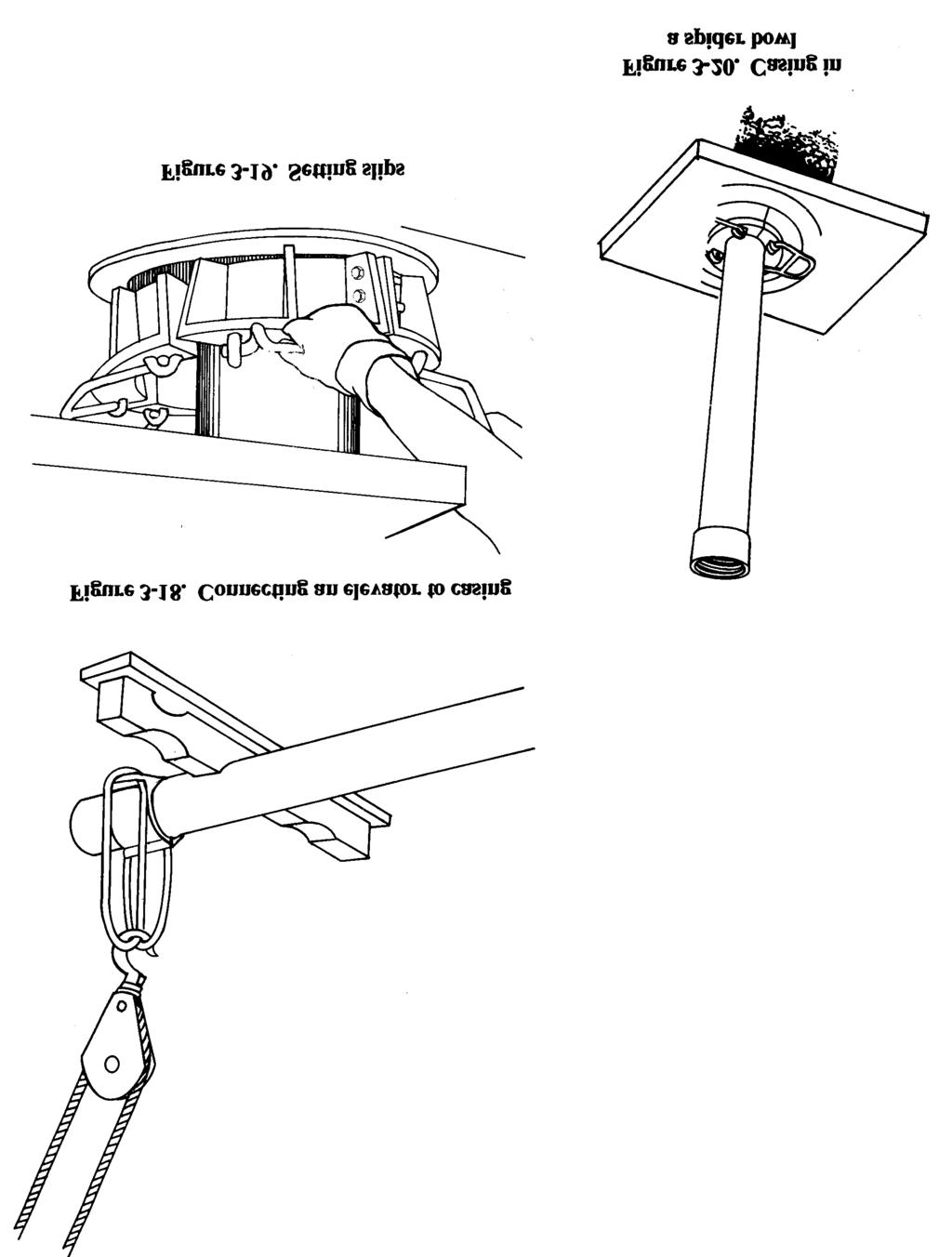
81 3-19
82 b. Screening. You can use the following method to install screens: Step 1. Place a casing section in the well. Cap the casing on the lower end so materials from the bottom of the well will not enter the well. Step 2. Suspend a screen section over the well and attach the screen section to the casing section. Step 3. Lower the screen and casing section. Suspend them in the well either by the elevator resting on the rotary table or by slips in the spider bowl. Step 4. Add casing until the screen reaches the desired depth. Chapter 5 discusses other methods of screening. c. Filtering and Backfilling. The last procedure when installing screen and casing is to place a gravel-pack filter around the screen and backfill material around the casing. If you place the screen in material such as gravel or very coarse sand, you may not need a gravel pack. Place the gravel filter material around the outside of the casing. Deposit the material to the bottom of the well. Add gravel to about 5 feet from the top of the screen. (Use the sounding method to determine the level of the gravel.) Add impervious backfill around the casing from the gravel pack to about 10 to 20 feet from the surface. If you use grout instead of impervious material, add a couple of feet of clay above the gravel to prevent the grout from entering the gravel filter. Bring the grout to the surface Well Development Frequently, when a well is frost installed, the efficiency (production per foot of drawdown) is not satisfactory, and you must develop the well either by pumping or surging or both. Developing a well removes the remaining drilling fluid, breaks down any filter cake buildup on the borehole wall, and flushes the fines in the formation (adjacent to the grovel pack) into the well. Make sure that you pump the well of all fine sediments and sand with an airlift before installing the submersible pump. If you do not, the pump and components will wear out prematurely. To develop a well, pump or blow the drilling fluid out of the well. Agitate the water in the well to produce an alternating in and out flow through the well screen (or gravel pack). There are several methods available to develop a well. The simplest method follows: Step 1. Attach a weighted plunger or surge block to the sand line. Lower the surge block into the well below the water level but above the screen. Step 2. Lift the block and then drop the block 3 to 4 feet, repeatedly, to surge the well. Continue this action for several minutes. Step 3. Remove the surge block and lower a bailer into the well. All of the sand that was pulled into the well is bailed from the sand trap. Step 4. Repeat the process, noting the amount of sand brought into the well each time. Development is complete when 5 milligrams or less of sand per liter of sampled water is removed. Step 5. Sanitize the well with calcium hypochlorite Sanitary Seals. All wells must have a sanitary seal to prevent contamination from surface runoff. Mix cement grout and place it in the annulus between the well casing and the borehole wall. Extend the grout from the surface to the top of the backfill material (30-foot minimum). You should also pour a concrete platform (about 4 feet by 4 feet) around the casing at the surface with the casing extended at least 1 foot above the surface. The upper surface of the slab and the surrounding area 3-20
83 should be gently sloping away from the well for better drainage. In addition to a surface grouting, you need to install a well seal (a type of bushing or packing gland) to prevent foreign materials from entering the inside of the well casing. You normally install the well seal when you install the pump, which is after you complete all development, testing, and disinfecting Pumping Tests. After installing a well, you should perform a pumping test. The test will show you if the well can produce the required amount of water. If the well is considered permanent, the pumping test should help you evaluate any future performance deterioration. Evaluation parameters are flow rate, time, and drawdown in the well. Before you start the test, place a sounding device, such as an M-Scope, in the well to measure the water level during the test. You must also measure and regulate the flow rate during the test. The most proficient way to measure the flow rate is with a flow meter. However, you can use a calibrated container and a stop watch. Use the following procedures to perform the pumping test: Step 1. Temporarily install a pump in the well below the anticipated drawdown depth but above the screen. Step 2. Measure the static water level and start the pump. During the test, one team member should monitor the flow rate and try to keep the flow rate constant. Step 3. Record the drawdown with the flow rate. Take early readings quickly; then spread out the readings as testing progresses. An ideal reading schedule would be the initial reading and then a reading at 30 seconds, 1 minute, 2 minutes, 4 minutes, 8 minutes, 15 minutes, 30 minutes, 1 hour, 2 hours, and so forth. You must record the exact times you take readings of the drawdown and flow-rate measurements. The length of a test usually depends on the purpose of the well, the urgency for water, and the time available. On small water supplies, you can perform an adequate evaluation in 4 to 5 hours. For large, permanent supplies, tests could take from days to weeks. The GPM, footage of drawdown, and available drawdown give an immediate indication of the well s capacity. If the pump from the well-completion kit is capable of producing more water than the well can, you should put a throttle or a valve on the pump. Doing so will help regulate water extraction and will prevent pump damage. Step 4. Set and adjust the pump. The well is now ready for use or for connecting to a treatment, storage, and distributions system. 3-21
84 Chapter 4 Pumps 4-1. Fundamentals. a. Pump Types. Pumps maybe classified according to use (for shallow or deep wells), design (variable or positive displacement), or method of operation (rotary, reciprocating, centrifugal, jet, or airlift). This chapter deals with shallow- and deep-well pumps. Shallow-well pumps (suction-lift pumps) are normally installed above ground, on or near the top of the well casing. Deep-well pumps are installed in the well casing with the pump inlets submerged below the pumping level. These inlets are always under a positive head and do not require suction to move or pump the water. b. Selection Criteria. Consider the following items when selecting a pump: Size of the well. Quantity of water to be pumped. Drawdown and pumping levels. Type of available power. Yield of the well. Estimated total pumping head. Well yield is frequently overlooked when selecting a pump for small wells. Installing a pump that can handle a large discharge capacity can either temporarily drain a small well or exceed the maximum possible suction lift. Therefore, pumping requirements and well characteristics must be matched to determine the optimum pump for each installation. Table 4-1 (page 4-2) provides a general guide for use in pump selection. Military well drillers deploying with well-completion kits will normally use the deep-well submersible pumps that are supplied with the kits Shallow-Well Pumps. These pumps are limited to the depth from which they can lift water. At sea level, the practical limit is 22 to 25 feet for most pumps. This value decreases about 1 foot for each 1,000-foot increase in elevation above sea level. The operative principle of a shallow-well pump is similar to drinking through a strew. A partial vacuum is created, and the difference between the pressure inside the straw and the liquid outside the straw forces the liquid upward to a new equilibrium. A pump exhausts air from the intake line, thus lowering the pressure on the intake side below atmospheric pressure. The atmospheric pressure on the water in the well then forces the water up through the suction line into the pump. The atmospheric pressure is the only force available to lift water to the pump. At sea level, the force is about 14.7 pounds per square inch (psi) (about 34 feet of water). The maximum is never reached because pumps are not 100 percent efficient and because other factors (water temperature and friction or resistance to flow in the suction pipe) reduce the suction lift. Since a partial vacuum is required in the suction line, the line must be airtight if the pumps are to function properly. Threaded joints must be carefully sealed with pipe-joint compound and all connections to the pump must be tight. 4-1
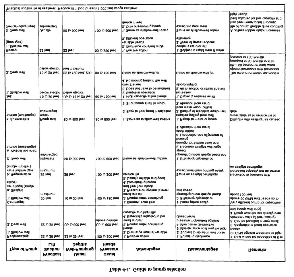
85 4-2


86 a. Pitcher Pump. This is a surface-mounted, reciprocating or single-acting piston pump (Figure 4-1). The pump has a hand-operated plunger that works in a cylinder designed to be set on top of the well casing. The suction pipe screws into the bottom of the cylinder. The plunger has a simple ball valve that opens on the downstroke and closes on the upstroke. Usually, a check valve at the lower end of the cylinder opens on the upstroke of the pump and closes on the downstroke. continuous upstroke and downstroke actions result in a pulsating flow of water out of the discharge pipe. By lifting the pump handle as high as possible, the check valve (lower end of the cylinder) will tilt when the plunger is forced down on top of the valve. Tilting the check valve allows the pump and suction line to drain. To reprime the pump after draining, pour water in the cylinder from the top of the pump. To maintain the pitcher pump, renew the plunger, check the valve leathers, and clean the suction pipe. Clean the suction pipe when it becomes clogged with sand, gravel, or other material. The pump will be noisy and the pump handle may fly up when released during the downstroke. b. Rotary Pump. These pumps use a system of rotating gears (Figure 4-2) to create a suction at the inlet and force a water stream out of the discharge. The gears teeth move away from each other at the inlet port. This action causes a partial vacuum and the water in the suction pipe rises. In the pump, the water is carried between the gear teeth and around both sides of the pump case. At the outlet, the teeth moving together and meshing causes a positive pressure that forces the water into the discharge line. 4-3

87 In a rotary gear pump, water flows continuously and steadily with very small pulsations. The pump size and shaft rotation speed determine how much water is pumped per hour. Gear pumps are generally intended for low-speed operation. The flowing water lubricates all internal parts. Therefore, the pumps should be used for pumping water that is free of sand or grit. If sand or grit does flow through the gears, the close-fitting gear teeth will wear, thus reducing pump efficiency or lifting capacity. c. Centrifugal Pump. These are variable displacement pumps in which water flows by the centrifugal force transmitted to the pump in designed channels of a rotating impeller (Figure 4-3). A closed case, with a discharge opening, surrounds the impeller. The case has a spiral-shaped channel for the water. The channel gradually widens towards the outlet opening. As water flows through the channel, speed decreases and pressure increases. The hydraulic characteristics of the pump depend on the dimensions and shape of the water passages of the impeller and the case. The centrifugal pump works as follows: Water enters the pump at the center of the impeller and is forced out by centrifugal force. (You may have to fill the pump and suction pipe with water before starting the pump.) The expelled water forces the water in the casing out through the discharge pipe, producing a partial vacuum in the center. Atmospheric pressure acts on the surface of the water in the well and forces more water up the suction pipe and into the impeller to replace the expelled water. (1) Head. Head is the pressure against which a pump must work the suction-lift and friction losses and the system pressure that the pump must develop. If the head is increased and the speed is unchanged, the flow rate will decrease. To increase the flow rate, you must increase the speed or decrease the head. If you increase the head beyond the pump s (shutoff head) capacity, water will not be pumped. The impeller only churns the water inside the case; the energy expended heats the water and the pump. If such action continues, enough heat may develop to boil the water and generate steam causing the impeller to rotate in vapor rather than water. With no coolant, the bearings seize, resulting in severe pump and possible motor damage. 4-4
88 (2) Connections. You may have to use several pumps to meet head or flow requirements. You can connect the pumps either in series or in parallel. If you connect two centrifugal pumps in series (the discharge of the first connected to the suction of the second), the discharge capacity stays the same. However, the head capacity is the sum of both pumps head capacities. The increased head capacity is only available as discharge head. You will not gain any appreciable increase in suction lift. You can obtain the same effect by using a multistage pump that contains two or more impellers within one casing. If you connect two centrifugal pumps in parallel (both suctions are connected to the intake line and both discharges connected to the discharge line), the discharge head is the same as that of the individual pumps. The discharge capacity is close to the sum of the capacities of both pumps. The increased flow rates result in extra friction losses that prevent the combined flows from being the exact sum of the two pumps. d. Self-Priming Pump. This pump has a priming chamber that makes repriming unnecessary when the pump is stopped for any reason other than an intentional draining. The pump is mounted on a frame with and driven by a two-cylinder, three-horsepower military standard engine (Figure 4-4, page 4-6). The unit is close-coupled. The impeller is secured to an adapter shaft that is fastened and keyed to the engine stub shaft. A self-adjusting mechanical seal prevents water from leaking between the pump and the engine. The pump is designed for optimum performance with a suction lift of 10 feet. You can operate the pump at greater suction lifts, but the capacity and efficiency of the unit are reduced proportionately. (1) Installation. Install the pump as close to the source of water supply as possible to minimize the required suction lift. Install full-sized suction piping and keep friction losses as low as possible by using the least possible number of pipe fittings (elbows, bents, unions). To ensure that joints do not leak use pipe cement or teflon tape on all joints. If you use a suction hose, try to ensure that the hose is as airtight as possible. If you have to remove the suction or discharge piping or hose frequently, you should make the connections with unions to reduce wear on the pump housing. (2) Priming. To prime the pump, remove the priming plug on top of the pumping case, and pour water into the pump case to the discharge-opening level. Failure to fill the priming chamber may prevent priming. If the pump takes longer than 5 minutes to prime, a mechanical problem exists. A self-priming pump is normally primed from a 10-foot suction lift in 2 minutes or less, depending on the length and size of the suction pipe. If you use a valve in the discharge line, you must open it wide during priming. If the pump fails to prime, look for the following: Plugged priming hole. Air leak in suction pipe or hose. Collapse of lining suction hose. Plugged end of suction pipe or suction strainer. Lack of water in pump housing. Clogged, worn-out, or broken impeller. Worn or damaged seal. 4-5


89 4-3. Deep-Well Pumps. a. Submersible Pump. This is a centrifugal pump closely coupled with an electric motor that can operate underwater. The pump is typically multistage containing two or more impellers (depending on head requirements) housed in a bowl assembly. Because the system is designed for underwater operations, it has a waterproof electric motor, watertight seals, electric cables and connections. The motor is located beneath the bowl assembly with the water intake screen between the two units. Military well-completion kits contain the submersible pump (Figure 4-5). The pump produces 50 GPM at 600 feet and is powered by a 15-horsepower, 460-volt, 3-phase electric motor. The pump comes with 700 feet of electrical conductor cable and 660 feet of 2-inch drop hose that supports the pump and brings the water to the surface distribution system. Currently, the submersible pump is the standard in deep-well, high-production systems. 4-6


90 The following improvements have made the submersible pump a reliable pump: Motors, cables, and seals have very low maintenance requirements. Noise levels are reduced because the motor is located in the well. Motor operates at a cooler temperature because it is submerged. System does not require long drive shafts and bearings, so maintenance problems and deviations in vertical well alignment are not critical factor when using this pump. The main disadvantage with the pump is that the entire pump and motor assemblies must be removed from the well if repairs or services are required. b. Turbine Pump. The turbine (line shaft) pump is a shaft-driven, centrifugal pump. The pump is hung in a well at the lower end of a string of pipe called the column pipe. The shaft, which drives the pump, runs through the column pipe and extends from the pump to the ground surface where it is connected to a pump-head assembly. Bearings in the column pipe are used to stabilize the shaft. The turbine pump (Figure 4-6, page 4-8) is a multistage pump containing several impellers or bowl assemblies. The main advantage to the turbine pump is the accessibility to the power source. The power source is either a hollow-shaft electric motor or a reciprocating engine connected by a right-angle drive and is located above ground. The main disadvantages are maintenance requirements for the shaft and bearings and the requirement that the well be vertical with no deviations for installation. c. Helical-Rotor Pump. This pump is a positive-displacement-, rotary-screw-, or progressingcavity-type pump (Figure 4-7, page 4-9). The pump is designed for relatively low-capacity, highlift wells that are 4 inches or larger in diameter. The main elements of the pump are a highly polished, stainless-steel helical rotor, a single-thread worm; and an outer rubber stator. The rotor is located in the stator. During the rotation process, the rotor forces a continuous stream of water forward along the cavities in the stator producing a uniform flow. The helical-rotor pump is designed to produce 50 GPM at 1,800 revolutions per minute (RPM) against a 250-foot head. 4-7
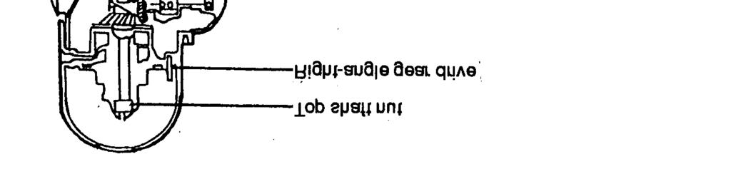


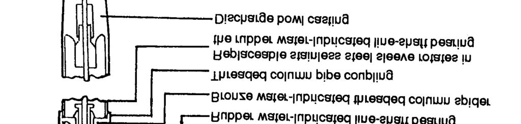


91 4-8


92 d. Jet Pump. This pump is a combination of a surface centrifugal pump, down-hole nozzle, and venturi arrangement (Figure 4-8). It can be used in small diameter wells that require a lift of 100 feet or less. The pump supplies water, under pressure, to the nozzle. The increase in velocity at the nozzle results in a decrease in pressure at that point, which in turn draws water through the foot valve into the intake pipe. The combined flow then enters the venturi where the velocity is gradually decreased and the pressure head recovered. The excess flow is discharged at the surface through a control valve, which also maintains the required recirculating flow to the nozzle. A jet pump s efficiency is low compared to an ordinary centrifugal pump. However, other features make the jet pump a desirable pump. They are-- Adaptability to wells as small as 2 inches in diameter. Easy accessibility to all moving parts at the ground surface. 4-9


93 Simple design resulting in datively low purchase and maintenance costs Air-Lift Pumps. a. Principle. Water can be readily pumped from a well using an air-lift pump. There are no air-lift pumps in the Army supply system; however, in the field, you can improvise and make a pump using compressed air and the proper piping arrangement. The assembly consists of a vertical discharge (eductor) pipe and a smaller air pipe. Both pipes are submerged in the well below the pumping level for about two-thirds of the pump s length. The compressed air goes through the air pipe to within a few feet of the bottom of the eductor pipe and is then released inside the eductor pipe. A mixture of air bubbles and water forms inside the eductor pipe. This mixture flows up and out the top of the eductor pipe. The pumping action that causes water to rise as long as compressed air is supplied is the difference in hydrostatic pressure inside and outside the pipe resulting from the lowered specific gravity of the mixed column of water and air bubbles. The energy operating the air lift is contained in the compressed air and released in the form of bubbles in the water. Figure 4-9 shows the operating air-lift principle. WARNING Air and fluids under pressure can cause injury. Make sure all air couplings are tight and that lines and hoses are in good condition. You should arrange an air lift with the air pipe inside the eductor pipe (Figure 4-10). You can use this arrangement for test pumping wells and for well development. You can use the well casing for the eductor pipe. However, to pump sand and mud from the bottom of a well during well development and completion, use a separate eductor pipe. This type of pump is also useful in wells that, because of faulty design, produce sand with the water. This condition will quickly create excessive wear on most pumps. By setting the educator pipe to the bottom of the screen, sand will be removed before it fills the screen. 4-10
 to determine submergence percentage: where x = vertical distance from A to C.")

 to get the required air pressure (psi). (3) Compressors.")

94 b. Installation Design. (1) Submergence. Submergence is the proportion (percentage) of the length of the air pipe that is submerged below the pumping level. Use the following formula and Figure 4-11 (page 4-12) to determine submergence percentage: where x = vertical distance from A to C. y = vertical distance from C to D. (2) Air Pressure. To calculate the required air pressure to start the air lift, you must know the length of air pipe submerged below the static level. See Figure 4-11 (page 4-12), area from point B to point D, for the starting air pressure. Divide the area from point C to D by 2.31 (constant/conversion factor) to get the required air pressure (psi). (3) Compressors. The 350 cubic feet per minute (cfm) compressor on military drilling rigs, such as the LP-12, is sufficient for operating an air lift. With a submergence of 60 percent, a lift not exceeding 50 feet and the compressor delivering 350 cfm of air, a well can be pumped at over 200 GPM. If you need more air, use another compressor in parallel. The maximum pressure that the compressor will produce is 200 psi, which is enough to start an airlift with about 420 feet of air pipe submerged. CAUTION Operate compressors upwind of the drilling rig. If you do not, dust could damage the equipment. 4-11
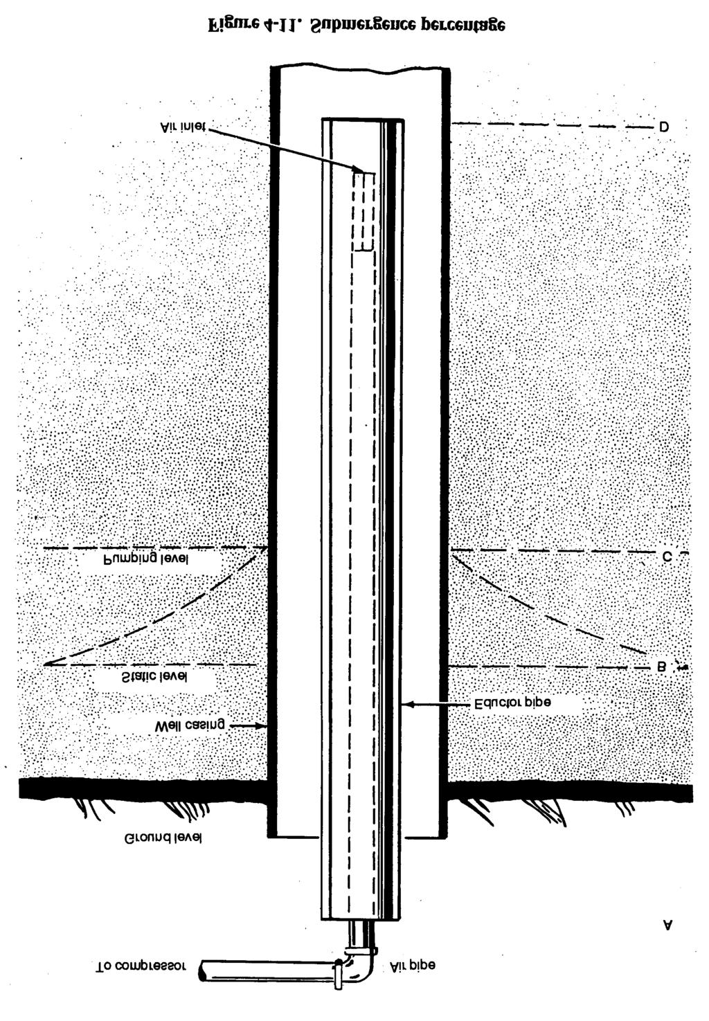
95 4-12

96 (4) Correct Air Amounts. For efficiency, the compressor must deliver the correct amount of air. Too much air causes excessive friction in the pipe lines and waste of air from incomplete expansion in the discharge pipe. Too little air results in a reduced yield and a surging, intermittent discharge. To calculate air-compressor requirements, see Table 4-2. (5) Performance and Efficiency. The performance and efficiency of an air lift vary greatly with the percent of submergence and the amount of lift. Generally, a submergence of 60 percent or more is desirable. If a well has a considerable pumping-level depth, you will have to use a lesser submergence percent. However, if the submergence is too low, the air lift will not operate. See Table 4-3 (page 4-14) for performance data for air-lift pumps corresponding to different submergence conditions and lifts. The values are for properly proportioned air and eductor pipes with minimum frictional losses. The efficiencies indicated in terms of gallons of water per cubic foot of air probably cannot be fully attained in military field operations. (6) Foot Piece. For best efficiency, the end of the air pipe should have a foot piece (Figure 4-10, page 4-11). This device breaks the air into small streams so that the bubbles formed will be as small as possible. You can make a foot piece by drilling numerous small holes in a short section of pipe. (7) Discharge Pipe. You can approximate the discharge-pipe length from Table 4-3. Lower submergence than those shown result in a lower pumping efficiency. The planned pumping rate must not cause an excessive drop in the water level, reducing the submergence. The two chief losses in the discharge pipe are air slipping through the water and the water friction in the discharge line. As the velocity of discharge increases, slippage decreases and friction increases. Eductor intake loss occurs at the lower end of the pipe due to friction and to the energy required to accelerate the flow of water into the pipe. 4-13
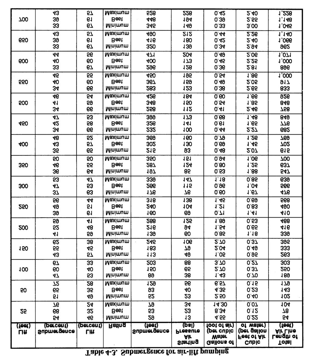
97 4-14
98 Part Two. Well Drilling Chapter 5 Well-Drilling Methods 5-1. Mud Rotary Drilling. Rotary drilling with mud is the most widely used method for water-well construction. A rotary drill rig has three functions: rotating the drill string, hoisting the drill string, and circulating the drilling fluid. A bit is rotated against the formation while mud is pumped down the drill pipe, through ports in the bit, and back to the ground surface through the annulus between the drill pipe and the borehole wall. (Table 5-1, page 5-2 shows the relative performance of drilling methods in various geologic formations.) Drill cuttings rise to the ground surface in the drilling fluid. Rotary drilling is sometimes called mud rotary drilling. Drill pipes or rods are joined to a bit to form the drill string. The drill pipe is the link transmitting torque from the rig to the bit, and the pipe carries the drilling fluid down the hole. a. Rotary Rigs. Rotary rigs vary in design. Drilling rigs are truck- or trailer-mounted and are powered by an on-board engine or by a PTO from the truck transmission. Power is delivered to the various components through hydraulic pumps and motors or through mechanical transmissions and clutches and geared on roller-chain drives. Many drill rigs may use both mechanical and hydraulic drives. Torque is applied to the drill string, which rotates by using three basic designs rotary table, top head, and quill-and-drive bar. Military drilling machines use rotary table drives. (1) Rotary Table. The rotary table is a rotating platform that transmits torque to the drill rod through the kelly. The kelly, which is attached to the mud swivel, is the uppermost section of the drill string that passes through the rotary table. The drill string may be square, hexagonal, or round with grooves or flukes on the outside wall. The drive kelly bar slides through the rotary table while rotating. By removing the kelly bar, you can add drill pipe and work the pipe through the open hole in the rotary table. The rotary table normally is a mechanical, positive drive mechanism. (2) Top Head. The top-head drive uses a power swivel. Torque is applied at the top of the drill string. The top-head mechanism moves down along the rig mast as the boring is advanced and is raised to the top of the mast to add a length of drill pipe. Top-head-drive drill rigs do not use a kelly bar. Most top-head drives are powered by hydraulic motors capable of variable speeds rather than positive constant rotation. (3) Feed Drive. Rotary rigs are equipped with a mechanism to apply a downward thrust to the drill string. This mechanism is called a pulldown or feed drive. Generally, two roller chains apply the thrust for rotary tables. The chains are attached to the kelly swivel and extended over sprockets at the top of the mast and under the rotary table. On older rigs, the sprockets under the rotary table are powered mechanically through a PTO and clutch. The pulldown chains on modem drill rigs are powered by a hydraulic motor, which provides better thrust control. 5-1
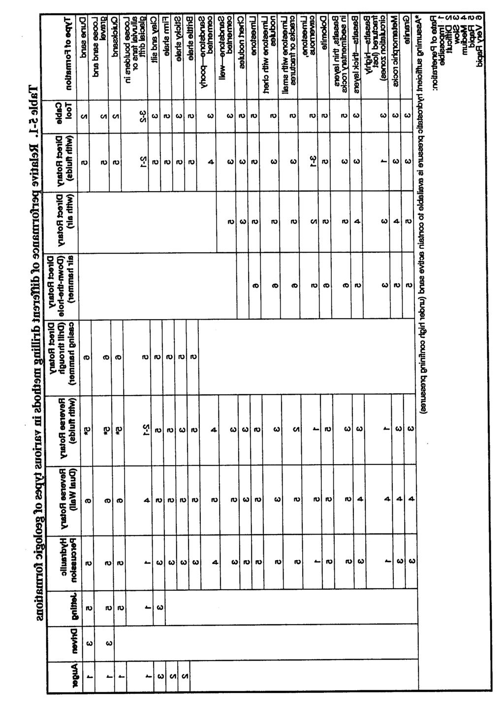
99 5-2

100 The thrust mechanism on most top-head rigs is a pair of roller chains consisting of two chain sections. One end of each section is attached to the swivel at the top of the kelly bar. The other ends are dead-headed to the top and bottom of the mast. Sprockets at the top and bottom of the mast act as idlers. Chains are powered in either direction by hydraulic rams. These rams apply thrust and are used in a hold-back mode to reduce the bit load of the weight due to the drill string. This chain mechanism is also the main hoist for lifting the drill string. (4) Mud Pump. A mud pump (Figure 5-1) on a rotary drill is usually a positive-displacement, double-acting piston pump with capacities ranging from one to several hundred GPM at pressures up to several hundred psi. Power may be provided through a mechanical PTO and clutch, with or without a separate transmission. Power may also be provided by a separate engine or a hydraulic or air motor. Other types of pumps are often used successfully, but their limited pressure capacity may jeopardize the success of the drilling operation. Most well-drilling machines have dual piston, double-acting, positive-displacement mud pumps. Pump capacity (volume and pressure) can limit the effective depth of a drilling operation. The horsepower required to drive a mud pump often exceeds the power required to hoist and rotate the drill string. (5) Hoists. Man drill-head hoists (draw works) are mechanically or hydraulically driven wire-line winches. On top-head rigs, the pulldown chains are used as the main hoist. Many drill rigs have auxiliary hoists for handling pipe and other equipment and for bailing. The bailing drum usually has less lifting capacity and a faster spooling rate than hoisting drums. Bailing drums can spool several hundred feet of wire line, which is sufficient to reach the bottom of most wells. Auxiliary hoists may be powered mechanically or hydraulically. b. Drill Bits. See Table 5-2 (page 5-4) for recommended rotating speeds for all sizes and types of bits in various formations. See Figure 5-2 (page 5-4) for bit selection. Appendix E discusses characteristics and maintenance for drill bits. (1) Tricone Roller Bits. These bits are best suited for brittle or friable materials. The tricone bit consists of three cone-shaped rollers with steel teeth milled into the surfaces. Tooth locations are designed so that as the cone rotates, each tooth strikes the bottom of the hole at a different location. Drilling fluid is jetted on each roller to clean and cool it. The cutting action is a progressive crushing under the point load of each tooth. Roller bits designed for rock, rocky soil (gravel), and soft formations (shale) have long teeth. The bits for harder formations have smaller, stronger teeth. The gauge teeth on bits designed for very hard rock are reinforced with webs. For extremely hard formations, milled teeth are replaced with connected carbide buttons. (2) Drag Bits. These bits are used in soil and other unconsolidated materials. The blades are designed so that they cut into the formation with a carving or scraping action. Drag bits may have multiblade, hardened-steel, finger-shaped teeth or may have connected carbide-reinforced cutting edges. 5-3
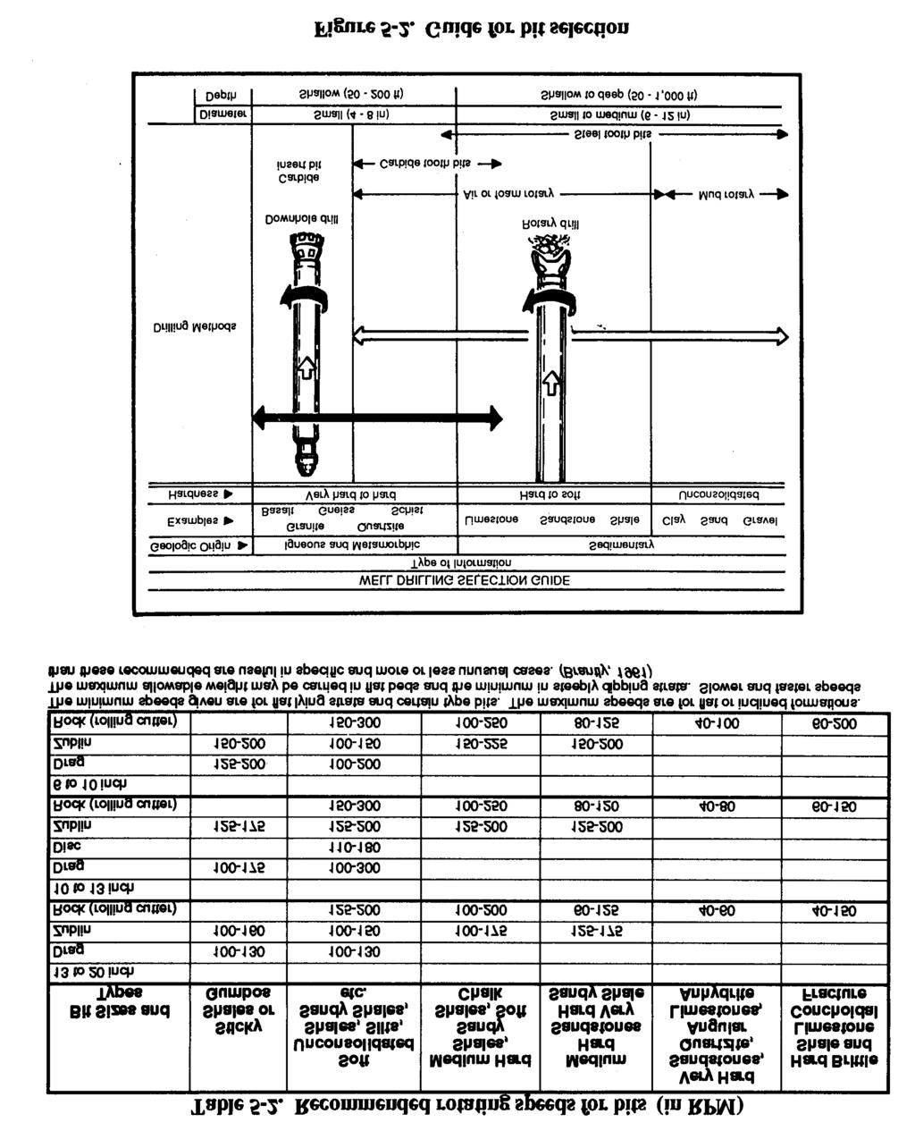
101 5-4


 for information on drilling fluids.")
 (page 5-18) for more information on mud pits. d. Variables.")
102 c. Rotary Operation. Standard rotary drilling involves the bit rotating against the formation. Drilling fluid is pumped through the drill string and face of the drill bit and backup the annulus to the surface. The rotary action of the bit loosens the material, while the drilling fluid cools and lubricates the drill pipe and bit and carries cuttings to the surface. The drilling fluid is under high hydrostatic pressure and supports the wall of the borehole against caving. The properties of the drilling fluid are important to the drilling operation. Well drillers must have knowledge of drilling fluids and their use for successful rotary drilling. Drillers must also know about drilling-fluid additives used to prevent problems in drilling. Preventing drilling problems, such as an unstable borehole wall or a stuck tool, is easier than fixing the problem after it occurs. See paragraph 5-1e (page 5-8) for information on drilling fluids. Before drilling with mud, build a mud pit. The pit may be either a portable pit or an excavated mud pit. The decision depends on the hole depth and the alternatives available. See paragraph 5-1e(9) (page 5-18) for more information on mud pits. d. Variables. Bit design, weight on bit, rotation speed, fluid consistency, and cumulation pressure and velocity affect rotary drilling. Experience helps the driller handle unique problems and conditions. Continue to experiment wherever you drill to develop the best drilling procedure. Before starting the hole, plumb the kelly to provide a straight hole (Figure 5-3). (1) Bit Design. Rotary drill bits are designed to cut specific material types. Choose the drill bit based on the anticipated formation. Either drag or rotary bits are available at a drill site. Normally, you will use drag bits for beginning a borehole in unconsolidated overburden materials. These bits are used for hard, medium, and soft rock and are part of the drilling-rig equipment. When drilling in soft rock, use a medium soft-rock drill bit. In very hard rock, stop mud rotary drilling; install casing to the rock layers, use a down-hole air hammer. The objective is to produce a hole quickly and efficiently. Be careful that you do not 5-5
103 penetrate too quickly. Producing cuttings faster than you can remove them can cause serious problems, such as the drill string sticking in the hole, excessive completion delays, and loss of equipment and the hole. (2) Weight on Bit. Adding weight on the bit increases the torque required for rotation. Too much weight can cause excessive penetration and produce cuttings that are too large and heavy. Large cuttings are difficult to wash out and may cause gumming and premature failure of the bit. Insufficient weight reduces or stops penetration and can produce fine cuttings. In cohesive soils, fine cuttings may thicken the drilling fluid and fail to settle in the mud pit. How weight is applied can also cause serious alignment problems and difficulty in well construction. Rotary-drilled boreholes spiral slightly and are seldom straight. Once spindling occurs, weight added by pulling down with the drill rig bends the string and magnifies the deviation. You should never use the chain pulldown to advance the hole beyond the first run (20 feet). Ideally, keep the drill string in tension. Add drill collars (heavy wall drill steel) at the bottom just above the bit. See Table 5-3 for drill collar weights. 5-6

104 CAUTION Use the pulldown feature on the drill rig as a last resort for short distances in hard strata. Bit weight required to cut rock depends on the design of the bit and the strength of the rock. Roller bits need a minimum of 2,000 psi of bit diameter for soft rock and shale and a maximum of 6,000 psi of bit diameter for hard rock. Before drilling, add drill collars instead of drill pipe until the load is sufficient for reasonable cutting. As you dig deeper and add drill pipe, you may have to hold back on the drill string. See Table 5-4 for weight on bit and rotary speed. (3) Drill Steel. Drill rods, collars, stabilize, subs, and bits are available in different sizes and materials. In most drilling systems, drill rods are either steel or aluminum and come in lengths of either 5 or 20 feet. (4) Rotation Speed. Rotation speed is determined by the weight on the bit and the material being drilled. Try to regulate the speed to produce the correct size cuttings. Experience will help you determine and regulate rotation speed. (5) Fluid Requirements. Fluid requirements depend on size, weight, nature of cuttings, and circulation velocity. Velocity depends on capacity and condition of the mud pump, annular area in the borehole, and the stability and permeability of the formation. See paragraph 5-1e (page 5-8) for more information on drilling fluids. Use the following calculation and Figure 5-4 (page 5-8) to estimate the mud-pump output and velocity and the hole size requirements: V = ( D 2 - d 2 )2 where V = velocity, in GPM. D = hole diameter or bit size, in inches. d = drill steel or drill collar diameter, in inches. (6) Circulation Pressure and Velocity. These elements of the drilling fluid are controlled by the pump capacity and speed. The fluid s density, velocity, and viscosity let it carry cuttings. If the drilling fluid is too thick, cuttings will not settle in the mud pit. Sufficient velocity with a fluid of low viscosity (even water) will carry drill cuttings to the surface. Excessive velocity will erode the wall of the hole to the extent of failure. 5-7


 Stabilizers.")
 will be straighter and easier to sample. The location of aquifers will also be easier to determine.")

 are the primary additives used in water-well drilling.")
105 Pump pressure results from flow resistance caused by viscosity, friction, weight of the fluid column, or restrictions in the circulating system. Pressure should be exerted at the ports in the bit, causing a downward jetting as the fluid exits. Regulate mud-pump pressure by varying the RPM of the pump. Mud-pump pressure against the bit is not harmful if it does not exceed the operating pressure of the pump. Other sources of fluid pressure can be detrimental. Pressure from friction occurs if the drill string is long for its inside diameter or pipes are internally upset. Frictional pressure increases wear in the pump. Pressure from the weight of the fluid column in the annulus or from a restriction in the annulus caused by an accumulation of cuttings indicates insufficient cleaning. This type of pressure can cause formation damage, resulting in lost circulation and wall damage. (7) Stabilizers. Unless the drill string includes stabilizers (Figure 5-5) for large drill bits, drill a pilot hole, using drill collars as stabilizers. The initial pilot hole (6- to 7 1/8-inch diameter) will be straighter and easier to sample. The location of aquifers will also be easier to determine. Use a larger bit to ream the hole to the desired size. Use overreaming bits, if available, because they follow the pilot hole best. e. Drilling Fluids. Drilling fluid is circulated in rotary drilling to cool, clean, and lubricate the drill string, to flush cuttings from the hole, and to stabilize the borehole wall. Water is the basic fluid and is satisfactory for lubricating and cooling the tools. However, water has limited abilities to carry cuttings and stabilize the borehole wall. Many drilling fluid additives are prepared and formulated for various purposes. Polymer fluids and water-based clay fluids (muds) are the primary additives used in water-well drilling. Table 5-5 lists drilling fluids. Mud cools and lubricates through heat absorption from the bit and reduction of drill-string abrasion against the borehole wall. Heat is generated as the bit scrapes and grinds. Without the cooling fluid, the bit would overheat and be useless. Research indicates that removing the cuttings around and under the bit is the most important factor in keeping the bit cool. Requirements for cooling fluid are less than those for removing the cuttings. 5-8
106 Therefore, if you keep the borehole clean with the fluid as you drill, you also cool and lubricate. This is true with clay muds and polymer fluids. Clay muds are colloidal suspensions. Solutions are chemical mixtures that cannot be separated by simple filtering. Suspensions are physical mixtures of solids and liquid that can be separated by filtering. This distinction underlies the difference in behavior between drilling polymers (solutions) and drilling muds (suspensions). You can mix natural clays with water for use as a drilling mud. Drillers often use water in shallow clayey 5-9

107 strata and depend on the formation clay to produce a suitable mud. Natural-clay mud properties are marginal for good water-well drilling. Hydrostatic pressure allows the fluid to support the borehole wall and is a function of the density or weight of the mud column. Important characteristics of a drilling mud are viscosity and weight to carry cuttings, gel strength, yield point, and active clay solids for filter cake. Use the following formula to calculate hydrostatic pressure: where For example, the hydrostatic pressure of a 200-foot hole with a mud weight of 9 pounds is as follows: 9 ft x 200 ft x = 93.6 psi. (1) Polymers. Polymer fluids are water-based and very low in solids. The polymer admixture can be organic, inorganic, natural, synthetic ors synthetically formulated natural polymers. Polymer additives are formulated for various drilling-fluid purposes and can be used alone or to enhance clay muds. Polymers, containing salt and other contaminants, are available and are compatible with water. Polymers are more sensitive to ph than are bentonite muds. Change the ph to effect desirable changes in the polymer fluid. Drilling-fluid weight impacts drilling rate and high-density drilling fluid reduces drilling rote. There is strong indication that the solids of a fluid have a similar effect as density. Polymer fluids are very different from clay muds because a large part of the polymer is soluble in water and becomes a solution when mixed with water. Long, complicated molecular chains tie up the water and can build viscosity without solids. In water-well drilling, many polymers are manufactured for producing drilling fluids, such as E-Z Mud, Revert, and Poly-Sal. E-Z Mud is a synthetic, inorganic polymer. Revert is a natural, organic polymer fluid derived from the guar plant. Polymers are generally best mixed through a mud gun. Polymers used for special purposes are available from the manufacture complete with specifics on how to use the product. Most polymers can hydrate more water than a high-grade bentonite. Up to ten times more bentonite is needed to build the same viscosity in a given amount of fluid, depending on the quality of the polymer. A polymer does not fully hydrate as quickly as bentonite. Mix the polymer very slowly through the mud gun a minimum of four hours before using for more complete hydration. The fluid will thicken as hydration continues, so do not mix to the desired viscosity. Some polymers possess physical qualities that can result in unusual hydration, gelling and viscosity. Follow the manufacturer s recommendations for hydration. Factors that affect the viscosity are quality of polymer, concentration and size of colloid, metallic ions in mixing water, temperature, rate of shear, and ph. Water is the primary building block for drilling fluids. Water quality affects the overall performance of drilling fluids. The action of bentonite in water is seriously impaired by dissolved acids or salty substances. Acidic water usually contains dissolved metals that cannot be used unless treated. Hard water affects the suspending and sealing qualities of bentonite. You can test the ph level by using paper ph strips. The ph level should be 8 to 9. If the water is too acidic, treat it with 5-10
108 soda ash at a ratio of 1 to 5 pounds of soda ash per 100 gallons of water. Following treatment, retest the ph level as before. Do not use water from wetlands, swamps, or small ponds for mixing drilling fluids because the water may be contaminated. If you use water from these sources, chlorinate the water before making the drilling fluid. Be careful because chlorine removes metallic ions that are necessary for viscosity in polymers. Adjust the ph of drilling water to 7.5. Temperature affects the viscosity and stability of some polymers. Consider the following examples: Seven pounds of Revert per 100 gallons of water at 45 F yields Marsh funnel viscosity of 125 seconds per quart. The same mix at 85 F yields 70 seconds per quart. A 0.87 weight mix of Revert at 68 F yields a viscosity above 90 seconds per quart for three and a half days. The same mix at 80 F maintains viscosity of 80 seconds per quart for only two days. Polymer drilling fluids can break down viscosity. Without treatment, the viscosity of some polymers (Revert) completely breaks down in one to six days depending mainly on temperature. You can correct this by adding chlorine. Revert requires Fast Break; E-Z Mud needs sodium hypochlorite at a ratio of 2 quarts for every 100 gallons of water. Other polymers, such as E-Z Mud and Poly-Sal, maintain their viscosity for long periods of time since natural breakdown is not significant. Table 5-6 (page 5-12) lists additives for drilling fluids. Polymer drilling fluids have virtually no gel strength because the colloids are nonionic and exhibit no attraction for each other. Most of the drill cuttings should be washed out of the borehole before circulation is stopped. A polymer fluid does not have thixotropic properties to hold cuttings in suspension. Shakers, desanders, or desilters are not needed when using polymer fluids. Since most of the cuttings are dropped out, friction and wear in the pump are minimized and the drilling rate is not impeded by cuttings or high density. A major advantage of polymers is the lack of mechanical wear to the drill-rig mud system. Some drilled fines (clay, silt) circulate back down the hole. Recirculated solids are much less a problem with polymer fluids than with clay fluids. Revert will not hydrate in water containing any appreciable amount of borate. However, Borax can be used to produce a gel plug in hydrated guar-gum polymer. With a ph of 7.5, the borate cress-links the polymeric chains and forms a strong three-dirnensional molecular gel. If a strong gel plug is necessary to get through a lost circulation zone, mix 1 cup of borax in 5 gallons of water and pour slowly into the pump section while pumping at idle speed. When the berated fluid (stringy gelled mass) recirculates, stop pumping for one-half hour. Resuming normal drilling should be possible after wasting the borated fluid. Repeat the procedure, if necessary. Although the polymer fluid is not thixotropic and has no gel strength, it thins somewhat while being pumped. 5-11
109 5-12
110 Polymer fluids build a type of membrane on the wall different from clay mud. Unnatural clay particles (bentonite) are not introduced into the hole. Since the polymer fluid is partly a thick solution, infiltration into the permeable wall is reduced. However, insoluble portions of some polymer colloids do exist. The insoluble and cuttings are surrounded with thick coatings that are more impermeable per unit thickness than a bentonite filter cake. The insoluble and cuttings seal the wall of the hole with a thinner, less active layer. The impermeable layer performs the same function as the filter cake in clay muds but does not restrict the annulus. The colloids in the polymer fluid are nonionic, have no chemical interaction, and are easier to remove in water-well development. When the viscosity of the fluid is broken, much of the cohesive function of the thin film becomes a water-like liquid and is washed out of the water well. Field testing of polymer fluids, using the falter press and the Marsh funnel, yields different results. The mud balance for measuring fluid density does not change. Weighing of the polymer fluid is limited. You can add sodium chloride to the fluid to bring the weight up to about 10 pounds per gallon. The addition of heavy solids (ground barite) is ineffective because of the polymer fluid s lack of thixotropic qualities. (2) Mud Products. Commercially processed clays for drilling are bentonite and attapulgite. Bentonite is superior except in brackish or salty water. (Use attapulgite in these waters.) Bentonite forms naturally from decomposition of volcanic ash when ground. Bentonite consists of aggregates of flat platelets in face-to-face contact. Bentonite is mined in many states, but the best grade (Wyoming bentonite) is mined only in Wyoming and South Dakota. Wyoming bentonite contains sodium montmorillonite (the active part of the clay mineral) and is small in size, which is important in building viscosity. Mud drilling fluids should be mixed with a mud gun. When agitated and sheared with water, the bentonite platelets absorb more than 25 times their own weight in water, separate, and swell. The amount of surface area wetted determines the ability of the particle to build viscosity. One ounce of Wyoming bentonite dispersed in water has more surface area than five football fields. Interparticle activity between platelets gives the mud its gel properties. The chemical composition of the mixing water affects the ability of bentonite to develop desirable qualities. These qualities can be manipulated by adding small amounts of various chemicals. (3) Mud Viscosity. True viscosity is a term relating only to true (Newtonian) fluids, such as water, and is a proportional constant between shear stress and shear rate in laminar flow. Drilling muds act differently in that the proportion between shear stress and shear rate is reduced when shear rate is increased. Drilling muds are thixotropic. The viscosity of a drilling mud refers to the thickness of the mud while flowing. Gel strength is the term used to describe the thickness of drilling mud at rest. Gel strength develops over a short period of time. Yield point is the mud quality broadly included in viscosity. You need more stress (pump pressure) to cause the gelled drilling mud to start flowing than to sustain flow once the gel is broken. The stress required to initiate shear or flow is the gel strength of the mud. The stress required to maintain shear is the viscosity. You want a higher yield strength with respect to the gel strength so the mud becomes very thin in flow shear. The primary function of viscosity is to help lift drill cuttings from the borehole. Other mud characteristics affecting lifting capacity are density, velocity, and flow patterns. Gel strength holds 5-13

111 the cuttings in suspension at the bottom of the hole when circulation is stopped. The stress (hydraulic pressure) required to break the gel strength to initiate cumulation can be detrimental. Required bottom-hole pressures can cause fracturing or opening of fractures in the formation, resulting in loss of drilling fluid, formation damage, and borehole wall damage. Down-hole pressure required to continue circulation depends on friction, density (or weight of fluid column), and viscosity of the mobilized fluid. These pressures can also cause serious problems. Therefore, it is desirable to use a drilling mud of relatively low density and viscosity, moderate gel strength, and high yield point relative to the gel strength (a very thin fluid in circulation). (4) Mud Testing. The Marsh funnel (Figure 5-6) is routinely used to give an indication of thickness or apparent viscosity of drilling fluid. The Marsh funnel is 12 inches long and 6 inches in diameter and has a No. 12 mesh strainer and a 1,000-milliliter (ml) cone. The funnel has a 2-inchlong, calibrated, hard-rubber orifice with an inside diameter of 3/16 inch. The funnel s cup is marked with a capacity of 1,000 ml. Use the following procedure for the Baroid Marsh funnel: Hold or mount the funnel in an upright position, and place a finger over the hole. Pour the test sample, freshly taken from the mud system, through the string in the top of the funnel until the level touches the top of the screen. Immediately remove the finger from the outlet tube, and measure the number of seconds for a quart of mud to flow into the measuring cup. Record time in seconds as funnel viscosity. NOTE: Calibration time for fresh water at 70 F is 26 seconds. The funnel viscosity measurement obtained is influenced considerably by the gelation rate of the mud sample and its density. Because of these variations, the viscosity values obtained with the Marsh funnel cannot be correlated directly with other types of viscometers and/or rheometers. Graduated in cubic centimeters (cc) and fluid ounces, the 1,000-cc measuring cup is designed specifically for use with the Baroid Marsh funnel viscometer. A quart volume is clearly marked on the measuring cup. The desired mud consistency depends on many factors. The nature of the formations will dictate mud qualities. However, you will not know all the conditions before you start to drill. The inexperienced driller must be careful because mud with the correct thickness often is too thin. You can adjust the viscosity by adding water or clay. A good range for drilling muds is 32 to 50 seconds per quart. Viscosity is influenced by mud density, hole size, pumping rate, drilling rate, pressure requirements, and geology. Considering the thixotropic qualities of drilling mud, a funnel viscosity of 100 seconds per quart may be no more viscous than a funnel viscosity of 50 seconds per quart if both fluids are in motion. You can use test readings as an indicator of changes in mud that might lead to problems. Therefore, conduct Marsh-funnel tests before beginning operations and record the findings. Take 5-14
 required for circulation, and the ability to drop cuttings in the")


112 mud samples for each test from the same location in the circulating system just before returning to the hole. The apparent viscosity of the drilling mud in motion affects carrying capacity, the pump pressure (hydrostatic down-hole pressure) required for circulation, and the ability to drop cuttings in the settling pit. These characteristics are also intrinsically involved with well hydraulics, density of mud, density and size of cuttings, and particle slip. (5) Density. The carrying capacity of a mud is affected by its density and the density of the drill cuttings. If the cuttings are denser than the fluid, they will descend. The magnitude of the difference in density, particle size, and fluid viscosity affect the rate at which a particle descends. Particle slip denotes this downward movement through the fluid. Ignoring thixotropy, the actual downward particle slip is constant regardless of velocity of flow. However, when the upward velocity of fluid exceeds the downward particle slip, the new movement of the particle is upward. Up-hole velocity plays a major role in determining the carrying capacity of the cumulating fluid. The practical limits of up-hole velocity depend on pump size and capacity, inside diameter (ID) of the drill string, jet size in the bit, viscosity of the fluid, cross-sectional area of the annulus, and stability of the borehole wall. Up-hole velocity is not as simple as the comparison of pump capacity, drill string ID, and annulus. Up-hole velocity is not a constant. The density of the drill fluid serves other purposes in rotary drilling. Heavy fluids can control (hold down) formation pressures encountered in drilling. You can build heavy mud by adding a weighing material such as ground barite (specific gravity 4.25). Prepare drilling mud in excess of 20 pounds per gallon by using barite. First, mix bentonite and water to build viscosity. Then, add finely ground barite so the mud will hold the barite in suspension. Use heavy drilling mud only when absolutely necessary to control pressures since the muds have disadvantages. High-density mud increases pressure on the formation by the weight of the fluid column. Figure 5-7 shows the nomograph for determining the hydrostatic head produced by drilling fluids. The increased pressure is further increased by the pump pressure required to mobilize the fluid in circulation. The increased pressure can cause formation damage and loss of circulation. In formations that are strong enough to withstand the pressures without being damaged, the drilling operation can still suffer. The pressures from the mud and the formation should be balanced so that the borehole bottom exposed to the drill bit is near surface eruption from pore pressure. That balance makes the formation easy to fracture and enhances the cutting rate. If the mud pressure is much lower than the formation pressure, the borehole can be unstable. If the mud pressure far 5-15
113 exceeds the formation pressure, the cuttings may be suppressed and reground by the bit. The result of recutting reduces bit life and lowers drilling rate. Mud density is increased by drill cuttings; the mud rising in the hole is heavier than the mud returning to the hole. All cuttings should be removed from the drilling mud in the settling pits and not recirculated. Although 100 percent removal is unrealistic, well-designed mud pits and mechanical screens, desanders, and desilters materially aid in removing cuttings from the mud. Water weighs 8.34 pounds per gallon. Clean, low-solid bentonite mud can weigh 8.5 to 9.0 pounds per gallon; try to maintain that weight. Increasing density of the mud during drilling indicates that the mud contains native solids. The drill s penetration rate could be exceeding the combined effort of the mud pit, desanders, and fluids to effectively separate solids from the drilling mud. To correct this problem, slow down the penetration rate and run the desanders to remove the solids. You can determine the density or weight of the drilling mud using a mud balance. Fill the mudbalance cup with mud, and place the inset lid in the cup. Excess mud will be displaced through a hole in the lid. Clean the outside cup area, place the assembly on the center pivot, and balance it using sliding weight. You read mud density as pounds per gallon and pounds per cubic feet. If you know the mud weight that enters and exits the drill hole, you can evaluate the efficiency of the mud pit and mechanical separators, determine when to clean the mud pit, and tell how well the mud is cleaning the hole. If you take samples from only one location, take them from the return end of the pit. (6) Filter Cake. Filter cake consists of solids from the drilling mud deposited on the borehole wall as the water phase is lost into the formation. Desirable properties are thinness and impermeability. Drilling mud is a colloidal suspension that can be separated by simple filtering. With the hole kept full of mud, the hydrostatic pressure inside usually exceeds the formation pressure. Occasionally, an artisan aquifer is penetrated, with formation pressure higher than the hydrostatic in-hole pressure. When the borehole pressure is higher than the formation pressure, the drilling mud tends to penetrate more permeable formations. Solids from the mud filter out and deposit on the wall, and the liquid phase of the mud (filtrate) enters the formation. Filter cake can be compacted against the wall by the excess hydrostatic pressure in the borehole. If the drilling mud is a well-conditioned bentonite and water mixture, most of the solids plastered against the wall will be flat platelets of highly active clay. The filter cake is self-regulating based on its degree of impermeability. As long as filtrate can pass through, the filter cake continues to thicken. A thick cake detrimentally increases down-hole cumulating pressure by restricting the annulus, making it difficult to pull the drill string because of the physical size of the drill collars and bit. In deep and somewhat deviated holes, the danger of key seating increases. Because a thick filtercake is of a lower quality and depends on its thickness to be effective, it is more easily damaged and eroded. A thick filter cake may indicate that the fluid has a high percentage of native solids. You may have to clean these solids from the mud before drilling progresses. A thin, highly impermeable filter cake bonds well to the wall and provides a surface for the hydrostatic pressures to act against to support the wall. Filtrate loss into the formation can account for significant fluid loss, if the consistency of the drilling mud is not good. Good consistency does not necessarily mean thick; it has to do with the bentonite content and the quality of falter cake. If a permeable formation is encountered with pore spaces too large to be plugged by the fine bentonite particles, the drilling mud will enter the formation. That mud loss can take the entire output of the 5-16
114 mud pump. The drill cuttings being carried up the annulus can sometimes be beneficial. The cuttings are coarser than the bentonite particles and may help bridge across formation pores. If you use this technique, maintain the normal drilling rate to supply the cuttings. Slow down the pumping rate to reduce pressure on the formation while bridging the open spaces. With sufficient bridging, a suitable filter cake follows, circulation is regained, and normal drilling operations are resumed. In the field, you can test the filtration properties and filter-cake thickness using the filter-press kit. This kit consists of a press with a mounted pressure gauge and a CO 2 charging system that is used to simulate the hydrostatic pressure inside a 200-foot hole. By placing a sample of drilling mud in the press and charging the system, you can forma filter cake. The filter cake should be less than 2/32-inch thick. (7) Salty Environment. A high chloride content in the mixing water causes bentonite to react anomalously or not react at all. The ground bentonite remains agitated; it does not disperse, hydrate, or swell. In salt water, bentonite is an inefficient clay additive for drilling mud. The dissolved salt is an electrolyte that changes the interparticle activity of bentonite. If you add sufficient amounts of salt water to a fresh water and bentonite mud mixture, the dispersed platelets will form lumps. Viscosity and filtrate loss increase and the mud s ability to build a thin, impermeable filter cake decreases. Attapulgite is often used for salty formations. The small particles produce a high surface-area-to-volume relationship and good viscosity building. Unlike bentonite, the particle shape is needle-like. Viscosity building in attapulgite depends on the entanglement of these needles. The disorderly arrangement of the particles accounts for the poor filtration qualities of attapulgite. The filter cake is more like a layer of strew or sticks. Attapulgite clay does not have the physical qualities to build a thin, impermeable filter cake. If you can mix bentonite in fresh water first and then add salt water as make-up water, the bentonite flocculates; that flocculation can be reversed by chemical treatment. (8) Well Hydraulics. You must have a basic understanding of well hydraulics. Fluid is pumped down the drill string, out the ports in the bit, and up the annular space between the drill string and the wall. The fluid empties into the mud pit, through any mechanical solids separating equipment, and is picked up from the pit by the mud pump for recirculation. The system is intended as a conservation system. Except for mud lost into the formation or where artisan water exceeding hydrostatic pressure flows into the hole, the return is largely complete and the mud-pit level does not change. Even if thes system is in equilibrium, you need to understand the up-hole rearrangement of flow patterns. Fluids flow in two distinct patterns. Laminar flow is orderly. The streamlines remain distinct and the flow direction at every point remains unchanged with time. Turbulent flow is disorderly. The flow lines and directions are confined and heterogeneously mixed. The type of flow depends on the cross-sectional area of the fluid course and the velocity, density, and viscosity of the fluid. In water-well drilling, the cross-sectional area of the annulus is usually several times that of the inside diameter of the drill string. Because of the increase in volume in the annular space, flow at the point the fluid leaves the bit is turbulent. The fluid becomes laminar flow when it begins flowing up the annular space. The returning fluid velocity is slower and the drill fluid is more dense and probably has more apparent viscosity, which affects the flow pattern. To clean the hole and carry the drill cuttings out, turbulent flow in the annulus would be better. 5-17

115 Picture the flow in the annulus as a series of nested tubes. Velocity varies as if these tubes were sliding past one another while moving in the same direction. Flow near the wall and near the drill string is at a slower rate than near the center. Cuttings near the center can be vigorously lifted while cuttings near the wall and drill string actually slip in a net fall. Rotation of the drill string changes the flow pattern near the drill string and materially enhances particle lift. For example, if you use a 3 1/2-inch ID and 4-inch outside diameter (OD) pipe to drill a 9-inch hole and pump 200 GPM, the velocity of the ID pipe is 400 feet per minute (fpm) and the velocity of the OD pipe is 75 fpm. To test cumulation at these rates (bit is 300 feet deep), pump down a marker (strew or oats). The majority of the material should take 4 minutes and 45 seconds to return (300 feet at 400 fpm takes 45 seconds and 300 feet at 75 fpm takes 4 minutes). To clean all the cuttings from a 300-foot depth with an average up-hole mud velocity of 75 fpm will require more than four minutes of pumping. Consider this concept regarding sampling cuttings from the return mud. If cuttings remain in the annular space between the drill rod and borehole wall when circulation is stopped, they will produce a denser fluid than the clean drilling mud inside the drill rods. The denser mud in the annular space will then flow down the hole and force the clean drilling mud up the drill rods. This causes a geyser effect, and the drilling mud may shoot several feet into the air until the mud columns equalize. (Some drillers mistake this for a caving hole.) If this situation happens when adding drill rods, the circulation time should be increased after drilling down the next rod. Use the following formula to calculate the annular space volume where V = annular space volume, in cubic feet. D = hole diameter or bit size, in inches (Figure 5-4, page 5-8) d = drill hole or drill steel collar diameter, in inches (Figure 5-4, page 5-8) L = hole length, in feet (Figure 5-4, page 5-8) (9) Mud Pits. Rotary chilling preparation is the design and excavation of an in-ground mud pit or installation of a portable mud pit and the mixing of the drilling fluid. For standard drilling operations that use well-completion kits, well depths could range from 600 to 1,500 feet. For wells up to 600 feet using the 600-foot WDS, use portable mud pits. For wells over 600 feet, use dug mud pits. In either case, you will have to clean cuttings from the pits as drilling progresses. Design considerations include the anticipated depth and diameter of the drill hole, since the material cuttings from the hole will be deposited in the mud pits. The volume of the pits must equal the volume of the completed hole. Therefore, during drilling, you will have to clean the cuttings from the pits frequently. If you have a backhoe to dig and clean the pits, size and depth of the pits are not critical. If you must dig and clean the pits with shovels, width and depth are important. Drilled cuttings should drop out of suspension in the mud pit. Therefore, long, narrow pits are better. Figure 5-8 shows a mud-pit layout and a chart depicting mud pit capacities and dimensions. NOTE: Portable mud pits will require constant cleaning. 5-18

116 Mud pits are part of the circulating system for mixing and storing drilling fluid and for settling cuttings. The ground slope will affect site layout. Pit design can enhance pit performance. Most drillers agree&t using multiple pits is best when dropping drill cuttings from the fluid. The volume of the pit should be one and one-half to three times the volume of the hole. This will provide fluid to fill the hole and an excess volume to allow stilling and settlement or processing before returning to the drill string. A volume of three times the hole volume will minimize drilling-fluid and mud-pit maintenance. Figure 5-9 (page 5-20) shows a mud pit that is prepared on-site. Figure 5-10 (page 5-20) shows a portable mud pit. 5-19
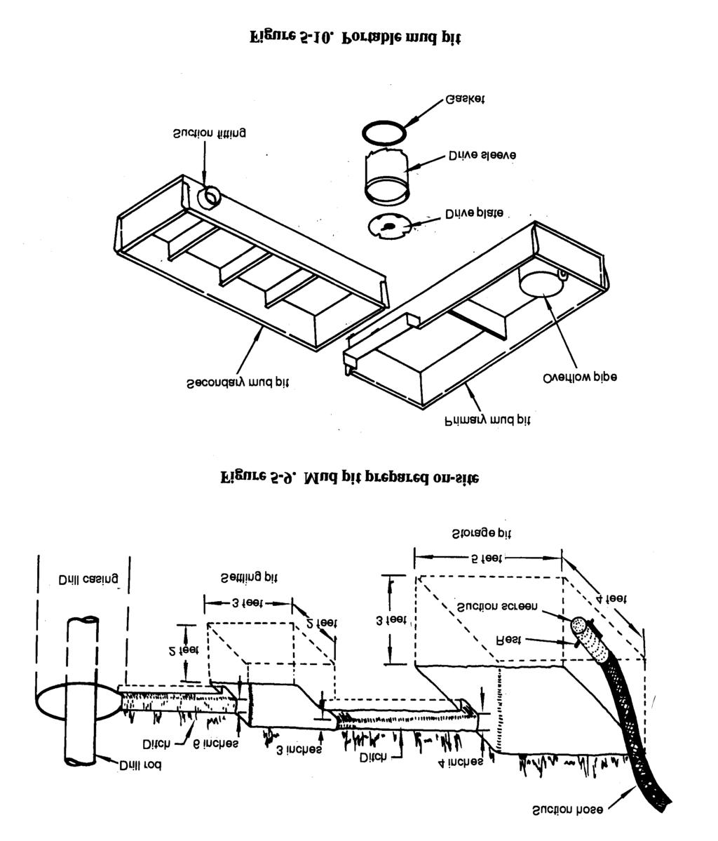
117 5-20
118 If drilling mud is processed through shale shakers, desanders, desilters, and space and time for cuttings settlement are not important, long, narrow pits connected at opposite ends by narrow, shallow trenches are preferred. If using a polymer fluid that has no thixotropic qualities, the settlement of cuttings is a function of time at low velocity or no flow. With polymer fluid, a long-path mud pit is ideal; if part of the flow almost stops, cutting settlement is enhanced. If you use a clay-based mud with thixotropic qualities and the mud moves slowly or flow stops, the gel strength can hold the cuttings. High velocity through narrow, shallow trenches holds the cuttings in suspension. If mud runs over one or more wide baffles or weirs, flow shear and velocity are low. These factors enhance cuttings to drop out. If mud processing equipment is available, use it. Recirculating clean fluid reduces power requirements, wear, and erosion and enhances drilling rate. See Figure 5-11 and Figure 5-12 (page 5-22) to calculate weir dimensions and volume. 5-21
119 f. Rotary Drilling Problems. Some problems in rotary drilling are minor and others are serious and can result in failure to complete a hole or even loss of equipment. Many serious problems start minor but can become serious if not recognized or handled properly. For example, in a loose sand zone, the borehole walls can slough and cause drilling fluid loss. By reducing or increasing fluid velocity, you can stabilize the wall and regain fluid circulation. However, if you do not recognize the condition and you continue drilling, the wall will slough and create a cavity. The cuttings lose velocity, become suspended in the cavity, and tend to fall back into the hole when you add a rod. This action can result in the rods or the bit becoming stuck in the hole. Other problems can result from subtle changes in geology, imbalances in the drilling operation, or equipment failure. 5-22

120 (1) Lost Circulation. Lost circulation refers to a loss in volume of drilling fluid returning to the surface. The implication is that some fluid pumped down the drill pipe is entering the formations. The mud pit will lower, since some of the mud is used in forming a mud cake on the borehole wall; however, increased lowering can indicate circulation loss. Losses can occur through open-graded sand or gravel or open joints in rock. A loss can occur when cuttings are not washed out and the borehole annulus becomes restricted, resulting in increased down-hole pressure. Spudding (raising and lowering the drill string) the hole too violently can cause loss. Spudding helps wash cuttings, but down-hole pressures increase momentarily. Experienced drillers can estimate when spudding is safe. When fluid cumulation is lost and a driller continues to drill, he is drilling blind. An experienced driller that knows the rig can often drill blind successfully, but reestablishing circulation is always safer. Reestablishing circulation can involve several techniques. You can add commercial items such as chopped paper, straw, cottonseed, and nut hulls to the mud pit. Sometimes, while the loss zone is grouted and redrilled, the grout is lost into the formation. In this situation, you may have to set casing through the loss zone. Occasionally, reducing fluid velocity while continuing to drill will plug the loss zone with drill cuttings. Reestablishing circulation is usually a trial-and-error process. The longer you drill without circulation the more difficult it will be to reestablish circulation. (2) Fall-In. Fall-in is material that accumulates in the bottom of the borehole after you stop cumulation. This material is borehole-wall material that results from sloughing or caving or cuttings previously carried in suspension. Fall-in occurs when you encounter a loose, unstable formation and the drilling-fluid weight is insufficient to stabilize the formation. If you anticipate or suspect fall-in, raise the drill bit off the bottom of the hole (20-foot minimum) each time drilling is interrupted. This will prevent the cuttings and fall-in from settling back around the bit until the problem is solved. (3) Stuck Drill String. The drill bit and any collars just above the bit are larger in diameter than the drill pipe. The string becomes stuck when cuttings collect on the bit and collar shoulder. This condition is called sanded in. Be careful because you can break the drill pipe while trying to remove the drill string. Regaining circulation and working the sand out are seldom successful. If the formation will not take the fluid when you engage the pump clutch, the relief (pop-off) valve will operate to relieve the pressure. Little can be done to free the drill string except to wash a small pipe down the annulus to the bit and jet the settled sand back into suspension. When the annulus is too small to pass a jet pipe, a part of the drill string may be lost. When the annulus is small, excessive up-hole velocity can promote erosion of the filter cake in granular zones and allow caving against the drill pipe. If this occurs, try to maintain circulation and rotation, even if circulation is slight. Where the grains are angular, the drill pipe can become locked while being rotated. This situation is similar to a sanded-in bit. With smooth pipe (not upset), hammering up and down will sometimes dislodge the string. You can reestablish circulation 5-23

121 and continue drilling. Be careful because hammering up and down can produce unfavorable compacting of the sand. In a hole of fine-grained soil or shale, where the alignment has significantly deviated and the drill pipe has wallowed into the wall, the pipe can become wall stuck. Pipe friction and relatively high borehole pressure can move the pipe tighter into the wallowed groove as you pull the string. An alert driller should recognize early stages of deviation and take measures to realign the hole. (4) String Failure. When the drill string parts, leaving a portion in the borehole, the drill string is rung off. The portion in the borehole is a fish and attempts to retrieve the portion is fishing. Fishing tools include a tapered tap and an overshot die (Figure 5-13). Ringing off is normally fatigue failure in the drill-rod joints caused by excessive torque or thrust (repeated flexing and vibration that crystallizes heat-treated tool joints) or by borehole deviation (with flexing of the string). Examine drill rods for signs of failure. (5) Deviation. A deviated borehole is called going crooked. If you make the initial setup without plumbing the kelly, you can expect the borehole to go crooked. A crooked borehole usually amplifies other problems and can make a borehole unsuitable for a well. You should always anticipate deviation, since the borehole naturally tends to spiral from bit rotation. Variations in the formation badness may start deviation. Excessive bit load magnifies minor initial deviation. Use all available guides and collars and a reduction in bit load to minimize deviation. (6) Swelling Soil. The in-hole effects of swelling soil (shale or clay) that absorbs water from the drilling fluid is squeezing. The result is a borehole that is undergauged to the extent that you cannot pull the bit by normal hoisting methods. In such cases, you can cut back through the blockage with a roller rock-bit or a drag bit. Swelling can cause caving and failure of the wall. Keep water out of the formation to prevent swelling. Special polymer drilling fluid additives that limit water absorption are available. High quality bentonite forms a thin but highly impermeable filter cake Air Rotary Drilling. Air rotary drilling is similar to mud rotary drilling except that the fluid circulated is compressed air. The air is not recirculated. Using compressed air is advantageous when water for drilling is inconvenient, fluid is being lost to the formation while drilling, or you have difficulty washing sticky clay formations from the hole. Also, air rotary drilling requires much less development time. You may have to adjust air rotary techniques with each well you drill. Some disadvantages to air rotary drilling are that air cannot support the wall of a hole in an unstable formation, changes in the return air flow are not as readily apparent as in mud flow, and air is not as effective in cooling and lubricating the drill bit and string. a. Air Supply. Air has no density or viscosity, so cuttings are blown out of the hole at high velocity. The up-hole air flow is turbulent and more effective in lifting the cuttings. The lack of density and viscosity increases the particle slip so a continuous and high velocity up-hole flow must be maintained to keep the hole clean. An upward velocity of about 4,000 fpm is sufficient to clean 5-24
122 cuttings out of the hole. Cutting removal also depends somewhat on size, density, and amount of cuttings. Up-hole air velocity is computed by dividing the output volume of the air compressor, in cfm, by the cross-sectional area of the annulus of the hole, in feet. Air compressors are rated on the following items: Intake air volume. Condition. Compressors wear with use, causing capacity to decrease. Sea level. Output volume capacity is reduced about 3.5 percent for every 1,000 feet above sea level. Temperature. Efficiency is reduced when temperatures are above 60 F and is increased when temperatures are below 60 F. Rotation speed. Output from the compressor is directly proportional to the motor s RPM. Do not operate a compressor at lower RPM to reduce wear. Dry material drilled by air will create a large amount of dust when blown from the borehole. Inject water to control the dust. Depending on the nature of the material drilled, the amount of water could be 1/2 to 5 GPM. Water injection increases air density and improves carrying efficiency for the cuttings. Adversely, water can cause the cuttings to stick together, making them heavier and harder to blow out of the borehole, or the cuttings may stick to the borehole wall, causing constriction. Minor wetting or dampening makes some walls more stable; excessive wetting can cause a wall to fail. Adjusting the amount of water injected into the borehole takes experience. Air has no wall-stabilizing qualities. In soils where sloughing and caving are a problem, injection of a thin drilling mud (bentonite mixed with the injection water) will control the dust and can contribute to stability. In drilling large diameters (12 inches) with standard drill pipe (3 1/2 inches OD), the annulus equals 0.7 square feet. Using a 1,000-cfm compressor the up-hole velocity would be about 1,400 fpm, which is not enough velocity to remove cuttings. While penetration will progress, the cuttings tend to stay at the bottom of the borehole under the drill bit and are recrushed. These cuttings act as a pad under the teeth of the bit and prevent proper cutting action. The compressor normally cannot drill holes by straight air rotary. Use the following equations to estimate compressor size, up-hole velocity, and hole-size requirements for air drilling or Figure 5-14 (page 5-26) to determine up-hole velocity. The recommended up-hole velocities are: 3,000 fpm, minimum; 4,000 fpm, fair; and 5,000 fpm, good. Vmin= ( D 2 - d 2 )16.5 where Vmin D d and = minimum velocity, in cfm. = hole diameter or bit size, in inches (Figure 5-4, page 5-8). = drill steel or drill collar in diameter in inches (Figure 5-4, page 5-8). 5-25

. b. Foamers.")

.")

123 where V C Vmin = actual up-hole velocity, in fpm. = compressor capacity, in cfm. = minimum velociy, in cfm. Air drilling has a depth limitation because of water in the borehole. Air pressure must displace the head of water in the borehole before it can exit the bit. An advantage is that when you encounter water, it. will discharge with the air. As drilling progresses, you can estimate the amount of inflow to the well. When calculating the static head of water, remember that psi equals 1 foot of head or 1 psi equals 2.3 feet of water. For example, the minimum psi required to overcome a 400-foot static water-level column is psi (400 ft x 4.34 psi= psi). b. Foamers. Commercial foamers for drilling enhance the air s ability to carry cuttings and reduce the velocity required to clean the borehole. The foamer is mixed with the injection water but does not foam with gentle stirring; therefore, pumping is not hindered. Foam must be pumped at a pressure greater than the air-line pressure into which it will be injected. The foaming and mixing with air largely occurs when exiting the drill bit. If air flow is reduced from the volume required for air rotary drilling and the injection rate is tuned to the airflow, the foam leaves the hole as a slow-moving mass (Figure 5-15). The foam is laden with drill cuttings and the borehole is effectively cleaned with only 10 percent of the air volume required had foam not been used. You can drill boreholes 2 feet or more in diameter with a well-tuned air-foam operation using air compressors. See Table 5-7 for a list of common problems with air-foam systems. Commercial foamers vary and come with mixing instructions on the container. You may need only a few foamers to produce large volumes of rich foam. Less than one quart of foamer mixed with 100 gallons of water injected at a 2- to 3-GPM rate is sufficient for a 12-inch diameter borehole. The column of foam provides slight stabilization to the wall. You can increase the richness and density of the foam by mixing bentonite with the injection water before adding the foamer. A very thin fluid of 15 to 20 pounds of bentonite mixed in 100 gallons of water is suitable for injection in air-foam drilling. Adding foamer to this fluid in the same proportions as clear water, results in richer, more stable foam. This technique is sometimes called air-foam-gel drilling. The gel refers to the bentonite fraction. Because of the increased richness, stability, and density of the air-foam gel, the air s cutting-carrying capacity and the wall stabilization are enhanced. Foam reaching the surface must be carried away from the drill rig to avoid mounding over the work area. Foam eventually dissipates 5-26


 is at the bottom of the drill string.")
124 when exposed to the atmosphere. Use either of the following methods to remove the foam from the rig area: Method 1. Use a packer to seal the top of the surface casing around the drill pipe or kelly bar so either rotates freely. Fit the top of the surface casing with a T below the packer for connecting a waste pipe. As foam comes out of the waste pipe, remove it from the rig. Method 2. Place a T at the top of the casing with an air-line eductor that causes a vacuum at the top of the hole. The foam is vacuumed into and blown through the waste pipe. By using an eductor, you can observe and regulate the returning foam. The eductor is fabricated and the drilling operation does not usually require the full output of the compressor Percussion Drilling. This type of drilling involves crushing by impact of the teeth of the drill bit. Most percussion drills are actuated by compressed air (pneumatic percussion). Essentially, percussion drilling for water wells uses down-hole, pneumatic-percussion hammer drills. Down hole means the percussion motor (actuating device) is at the bottom of the drill string. Percussion drills are best suited for drilling brittle, moderately soft to hard rock. In hard rock with percussion drills, you can drill faster and more economically than with other drilling methods. The air blows the cuttings from under the bit and up the annulus to the surface. The air s ability to carry the rock chips depends primarily on high air velocity. An up-hole velocity of about 4,

125 fpm is required to remove cuttings. If drill penetration rates are high (30 fpm or more), you may need a higher up-hole velocity to clean the hole. To drill water wells with percussion drills, you need to balance drill paragraphmeters to the materials to be drilled. Down-hole hammer drilling with a large diameter hammer or bit (Figure 5-16) usually results in a very crooked hole unless you use drill stabilizers or drill the hole in two steps. For two-stage drilling, drill a small pilot borehole with a 6- to 6 1/2-inch bit on a small hammer using drill collars as stabilizers. Enlarge the borehole using a stinger bit for drilling. The Navy s well-drilling package contains the stinger bit. a. Equipment. Shallow holes for loading explosives in rock quarries and other excavations have been drilled by percussion. Percussion drills are used because they penetrate quickly, even through hard rock. Most percussive motors or actuating devices are above ground. Top-head percussion drilling is not practical for deep boreholes because too much energy is lost in the long drill string. The down-hole drill was developed for efficiency. This drill is adaptable to most rigs and can drill water wells to depths exceeding 2,000 feet. To operate the drill, you hoist, handle, and rotate the drill string and drill motor and have an adequate air supply. You can supplement the air supply with an auxiliary (tag-along) compressor through simple plumbing. The 600-foot WDS comes equipped with auxiliary air connections. During operation, an air-actuated piston impacts the drillbit shank. Porting within the drill case forces the piston up and down with the full force of the air pressure. The drill-bit shank is splined and can slide in the splines about 2 inches until fully extended. The bit is held in the drill by a retainer ring and can have several design shapes. Currently, all downhole bits are set with carbide buttons specifically formulated for the percussion application. The carbide button bit is more durable than other bits made from hardened steel. However, the drill bit dulls and buttons flatten from wear. A dull bit is less efficient, works harder, is easily damaged, and has a reduced production rate. Flattened carbide buttons can be reshaped with a green stone. An experienced operator recognizes excessive wear and knows when to reshape the button. A percussion drill bit should drill 1,000 feet or more in hard rock without reshaping. A properly maintained bit has the longest service life and drills the most economical holes. Sharpening and reshaping the carbide buttons are detailed procedures. See the manufacturer s service manual for these procedures. The object of reshaping the button is to restore the hemispherical shape without removing excessive carbide material. The cutting points on a reshaped bit will be about equal in length. The flat area of each button is symmetrical around the cutting point and each button wears equally, which makes reshaping simple. Marking the center of the flat with ink represents the original cutting point and is the same length from the bit body as the other buttons. Carefully grind the worn button to a round shape leaving a flat (1/16-inch diameter) at the ink mark. Grind each button consistently, realizing that the reshaped buttons will not be perfect. 5-28


126 b. Power. Operating the down-hole drill is not difficult. Percussion drills are designed to operate at air pressures of 150 to 350 psi. The percussion drill is an orifice that leaks air out of the system. Air passing through the percussion drill actuates the piston and exhausts into the hole. The air volume used to actuate the drill is consumed by the drill. As the air consumption of the percussion drill increases, the air pressure delivered to the drill increases (Table 5-8). For example, if a percussion drill consumes 150 cfm of air at 200 psi, you will need a compressor that maintains 200 psi while losing 150 cfm of air to drill at 200 psi. Compressors are positive displacement air pumps. Pressure is a function of chamber ratio and leakage within the displacement mechanism. For example, a 200-psi compressor will produce 200 psi in a closed receiver while turning a few RPM. The volume of air produced is a function of the displacement chamber, size of the cylinders or rotors, and the speed of rotation. Volume output is directly proportional to speed of rotation. Efficiency of the compressor is adversely affected by wear within the compressor and the elevation and ambient temperature. Energy output from any drill is directly proportional to the air pressure delivered to the drill (Table 5-8). The percussion drill reacts to a pressure differential between intake and exhaust. The pressure delivered to the drill is somewhat less than the gauge pressure at the compressor because of friction loss in the plumbing; pressure in the borehole increases with depth because of friction and the load of cuttings and water. Increased pressure in the borehole reduces the effective pressure differential cross the drill. You can calculate friction losses in plumbing and pressure at the bottom of the hole, but the calculations are not very useful. When drilling, you can hear the hammer operating in the hole when it reaches the bottom. If the hammer fails to start operating, do not let the bit rotate on the bottom of the hole because you could destroy the buttons. c. Procedure. Attach the percussion drill to the drill string or drill kelly and lower the drill until the drill sets on the material. Extend the drill bit (open position) in the splines. If you apply air with the drill bit extended, the air blows directly through the drill and the drill does not function (the piston is not actuated). Weight applied on the drill must be sufficient to push the drill bit into the drill (closed position) and hold it closed. While maintaining the load, apply air pressure and slowly rotate the drill. When these actions are balanced, the drilling operation is optimal. Balance is attained by experimenting during drilling. (1) Weight on Bit. The weight applied to the drill must be sufficient to hold it in the closed position while drilling. While the drill bit is splined and can move in relation to the drill, the bit should not move in the splines while drilling. The required weight on the bit (bit load) varies somewhat with percussion drills from different manufacture. With a given drill, the bit load varies with the air pressure used for drilling. The air pressure does not tend to enter the drill bit (open 5-29
127 position) however, the energy with which the piston strikes the bit shank is directly proportional to the air pressure applied. Consequently, you will need more bit load to keep the bit in the closed position with higher air pressure. See the manufacturer s manual for specific recommendations for minimum bit load. The range for a 6-inch drill generates about 2,500 pounds total bit load at 125 psi to 4,000 pounds total bit load at 200 psi. Increasing bit load above the recommended minimum does little to increase the drilling rate. To achieve an increase in production rate, add weight if it does not adversely affect the rotation speed or constancy. Too much bit load will Affect the constancy of the rotation, which is detrimental to drilling production rate. Damage the drill. Cause excessive wear and premature failure of the bit. (2) Plumbness. Water wells should be plumb and straight. Apply bit load by using drill collars to hold the drill string in tension. Most rigs have a mechanism designed for that purpose. Because the drill string is relatively flexible, loads applied from the top will cause the drill string to flex and can misalign the drill bit. This procedure can cause the drill to deviate from vertical. Continued top loading will exaggerate deviation. Apply bit load by adding heavy drill pipe sections (drill collars) at the bottom of the drill string just above the bit. If you add a sufficient load at the bottom, you can hold the drill string in tension while drilling. The borehole tends to be straight because of the pendulum effect. Borehole deviations from vertical are sometimes associated with fast drilling rates. Such deviations actually result from crowding the bit (trying to increase the penetration rate by overloading the bit). (3) Air Pressure. Exceeding the 350-psi rating of the drill is not possible with the supplied compressors. The energy output of the drill is proportional to the air pressure delivered. Try to operate the drill at the maximum air pressure available. Lubricate the drill, using an in-line oiler designed for operation at the maximum anticipated working pressure. To control dust, inject a small amount of water into the airline. The injection pump and plumbing can be extremely dangerous if failure occurs because they are subjected to maximum pressure. CAUTION Do not exceed the maximum air-pressure ratings of percussion drills. WARNING Rapid expansion of compressed air from bursting hoses and loose connections can cause injury. Only use replacement parts in the air system that the appropriate TMs recommend. (4) Rotation. As drilling progresses, adjust the bit rotation to the penetration rate. As the hole deepens, the bit should make one revolution equal to the length of exposure of the carbide buttons in the bit (about 1/3 inch). The rule of thumb is that the rotation rate (in RPM) should about equal the penetration rate in feet per hour. The rotation rate for percussion drilling is slower than for rotary drilling. For percussion drilling to function at maximum proficiency, the rotation must be constant. As the piston strikes the bit shank (about 1,200 blows per minute at maximum air 5-30
128 pressure), the constant rotation allows the bit buttons to chip continuously at new rock. If the rotation rate is not constant (stops and jumps), the buttons hammer several times atone place before jumping to new rock. Erratic rotation produces variable sized chips, which are harder to clean from the hole. Erratic rotation also causes the buttons to penetrate too deep, increasing drag on rotation and excessive wear and button breakage. There are two main causes for erratic rotation. Top-head-drive rigs rotate the drill string with a hydraulic motor. Even though you can apply tremendous torque, a hydraulic system does not produce positive movement but reacts to drag or resistance to drill string rotation. The hydraulic top-head-drive rig is highly susceptible to erratic rotation. The primary force resisting rotation is weight on the bit. If this weight is excessive, the hydraulic drive produces a series of pressure variations and the bit rotates in a sequence of starts and stops. Even with mechanical drive rotation, which is nearly positive movement, dragon the drill bit will cause twist in the drill string, resulting in erratic rotation of the bit. This occurrence is more pronounced in deep holes. The secondary cause of erratic rotation is borehole wall friction. You cannot eliminate all friction between the borehole wall and the drill string. The more a borehole deviates from being straight, the greater the friction. It is easy to visualize a distorted drill string caused by excessive top loading and how the distortion can cause increased borehole wall friction. Other contributors to borehole wall frictional rock abusiveness, poor lubrication of the drill string (injected or naturalwater condition), and poor cutting removal. d. Adjusting to Variables. Economical and satisfactory drilling, using the down-hole percussion drill, requires fine tuning of the variables. Efficiency is directly proportional to the air pressure delivered to the drill. Operating at the maximum air pressure should be the constant. The bit load, ideally a bottom string load, should exceed the maximum load required for the drill so the load can be properly adjusted by increasing hold back with the drill rig. Do not overload the bottom string because the drill string weight increases as the depth increases. Do not overload the hoisting capacity of the rig. Adjust the rotation speed to the penetration rate and use the constancy of the rotation to regulate weight on the bit. Air blows the rock chips from under the drill bit on up the annulus to the surface. Since air has no effective viscosity or density to float the chips, removal is a function of the velocity of the returning air. You will need a minimum velocity of 3,000 to 4,000 fpm. Larger diameter drill pipe reduces the area of the annulus, which effectively increases the velocity of a fixed air volume. If you cannot achieve the required up-hole velocity, add foam to help remove cuttings. Effectively removing cuttings as drilling progresses is critical. When the drill bit is extended in the splines to the open position, the maximum volume of air passes through the drill. Cuttings may not be removed efficiently from the hole, resulting in an accumulation of cuttings around the drill. Accumulation may increase when compressor capacity is insufficient to maintain maximum pressure while drilling. This condition may be signaled by the drill sticking, which retards downward movement and affects bit load and drilling energy. The sound of the drill indicates this problem. Apparent change in the air return, cuttings returned from the annulus, and other indicators learned from experience also indicate an accumulation problem. Detrimental effects of inefficient cutting removal include reduced penetration rate, damage to the formation by fracturing, induced instability in the hole wall, damage to or even loss of drilling 5-31
129 equipment, and loss of the borehole. Accumulation may be caused by insufficient drilling air volume, a percussion drill not suited for the hole, a sudden influx of groundwater, or too rapid a penetration rate (large load of cuttings). The alert driller will sense a problem before it seriously affects the operation. Keep the hole and blow out all cuttings before shutting off the air to add another rod. By raising the drill slightly, the bit is extended in the splines (open piston), the percussive action stops, drill bit penetration (production of cuttings) stops, and maximum air passes through the drill to clear cuttings from the borehole. The alert and efficient operator will use this technique as conditions dictate. The down-hole percussion drill is designed to operate in extremely unfavorable conditions. The service life can be dependable with proper care. Lubricate the drill during operation. Use the manufacturer s recommend injection of a minimum of one quart of rock drill oil during each hour of drilling. During drilling, the LP-12 is oiled with an in-line oiler plumbed into the drilling air line. Water injection into the air line is common and is not detrimental to the lubrication process. Drill rigs used for pneumatic drilling are equipped with a small, positive displacement pump (injection pump). Injecting water is helpful because it reduces dust at the surface, improves cuttings removal, and stabilizes the borehole wall. A water injection of 2 to 5 GPM is satisfactory. Adjust injection rates to the specific material drilled. Water injection improves lubrication of the drill string, provides some cooling of the compressed air and drill system, and is beneficial for rock drilling. When you remove the drill from the borehole, break it down, inspect it, clean it, and repair it, as necessary. Oil all machined surfaces and lubricate threads with tool-joint compound before returning the drill to the borehole or to storage. Often a drill is left idle in the hole for an extended period. If this occurs, lubricate the drill. Lift the drill off the bottom, close the water injection valve, blow air through the hammer, and add oil (1 to 2 quarts) to circulate and lubricate the surfaces. Reasonable service and care improve the life of the drill Reverse Circulation. Military well-drilling systems are not currently designed for reverse cumulation drilling. In rotary drilling, the circulating fluid is pumped at high velocity down the drill string and up the annulus. Weighty, thick building materials are dispersed in the fluid to help lift the cuttings. You will need additives because the annulus area is greater than the cross-sectional area of the drill pipe, and the upward velocity in the annulus is much slower than the downward velocity inside the drill pipe. Additives help stabilize the borehole wall and keep it open. With reverse circulation, fluid is sucked up the drill string at a high velocity and then moved down the annulus. The larger the annulus, the slower the descending velocity. This method of drilling is used primarily for large-diameter, shallow (over 300 feet) water wells in alluvial materials. a. Advantages and Disadvantages. Reverse circulation is most effective in granular materials with little cohesion. In cohesive soils, fluid will not clean the drill bit. The advantages of reverse circulation are Slow-moving fluid in the annulus--walls are less apt to erode. Additives--usually are not needed since the turbulence and high velocity inside the pipe lift the cuttings. Borehole wall cake--is finely filtered and easily removed during well development. The following lists disadvantages of reverse cumulation: 5-32

130 Stability--depends on excess inside pressure acting against the borehole wall. Borehole wall--is not sealed by an effective filter cake. Keep the borehole full and backed with a large water reserve to maintain an excess hydrostatic head. Make sure that the fluid level is several feet above the water table to ensure an excess head in the borehole. If the fluid level is not correct, an unexpected coarse zone can take a large volume of fluid and the wall will collapse. Reverse cumulation is normally used for large diameter (over 30 inches) holes, such as large irrigation wells. Permanent relief wells are often installed by reverse circulation because the well can be developed to a higher efficiency than with standard rotary drilling. Theoretically, in reverse circulation, the maximum depth would not be limited. The maximum depth without air assist is about 200 feet and with air assist is up to 400 feet. b. Rig Configuration. Rig configuration for reverse cumulation rotary drilling (Figure 5-17) differs from rotary drilling. Hoisting and rotating the drill-string procedures are similar, but you must change the fluid circulating system. All cuttings must pass through the drill string. These materials could be granular, large grovel, and small cobbles. Occasionally, cobbles or small boulders that are too large to pass can be wallowed to the bottom of the hole. When several large pieces accumulate in the hole, you will have to pull the drill string and remove the rocks, using an orange peel bucket or similar device. Most reverse cumulation rigs are 6-inch ID and include items such as the drill string and hoses. The ports in the drill bit are smaller to prevent large particles from entering and becoming lodged. Pumps are available that can pass granular soil but not without damage. Pumps are not designed to handle large gravel. To prevent cuttings from passing through the pump, a jet eductor is used to create a vacuum. Water is pumped through the eductor at a high rate (600 to 1,200 GPM) producing a vacuum approaching 28 inches of mercury and pulling large volumes of water and cuttings. Bolted flanged pipe connections are popular. The flanged joint makes a reasonably smooth joint inside, 5-33
131 and the large torque required to rotate the bit does not over tighten the joint. Air bubbles injected into the circulation system at the bit increase turbulence and velocity and decrease fluid density inside the drill string. Reverse circulation drill pipe is fabricated from 6-inch ID tubing with standard pipe flanges and air pipes. Generally, two 3/4-inch pipes are welded 180 degrees apart along the outside of the drill pipe with holes drilled through the flanges. These pipes are turned into the system near the bit. Compressed air is pumped through these pipes to assist in removing cuttings. The flanged pipe connections are adaptable to the air-pipe alignment. The rotating swivel at the top of the drill string is complicated by the need to inject air. Making connections to add a joint of flanged pipe is more time consuming than with standard screwed-joint drill pipe. A 20-foot length is about maximum for drill pipe. The vacuum lift is from the water level in the hole to the rotary water swivel; the maximum suction lift is 22 to 25 feet Drilling Information a. Driller s Log. Prepare a driller's log for every well drilled. The log contains data, such as water-bearing-strata information, you use to locate and drill a well. Figure 5-18 (pages 5-35 and 5-36) is an example of a well driller s log (Department of Defense (DD) Form 2678). Figure 5-19 (pages 5-37 and 5-38) is an example of a piping and casing log (DD Form 2679). These forms are in the back of this manual for reproduction and use. Items to record in the remarks section of the well driller s log could include the following: Changes in circulation, color, and consistency of drilling fluid. Observations of the cuttings carried to the surface. Depth to material contacts. Size and apparent classification of the cuttings. Fluid loss or gain. Penetration rate. Soil description (fine or course, clay or sand). b. Soil Sampling. Try to obtain good material samples, and log the depth from which the samples came. Cuttings continuously wash to the surface during drilling. These cuttings are useful but are not the samples mentioned above. To collect a specific cutting sample, stop drilling and continue fluid circulation to wash most of the cuttings from the hole. When the hole is clean, advance the bit through the sampling interval and stop. Collect samples from the fluid of the drilled section. Resume drilling after taking samples. Redundant sampling impacts on drilling progress. However, collect several samples regardless of schedule impact to obtain worthwhile information. Field modifications of well design are often required, especially when subsurface information has been sparse. In most cases, the changes made during well drilling are minor. For example, placing a screen a few feet higher or lower to match the position of the most gravelly part of an aquifer, or adjusting a grout interval to match an impermeable layer above the aquifer. 5-34
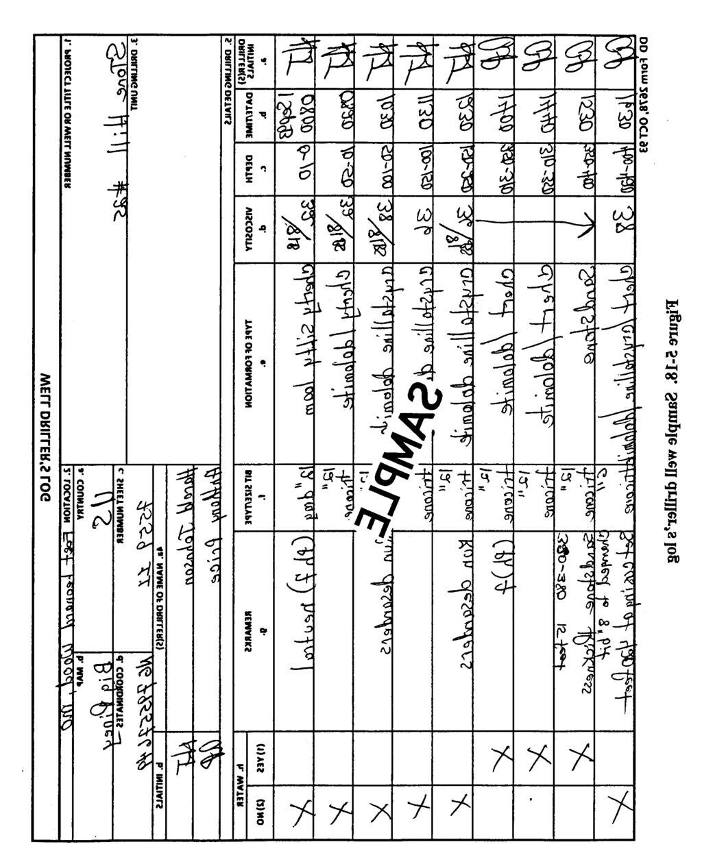
132 5-35
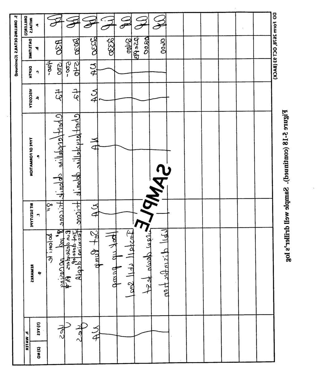
133 5-36
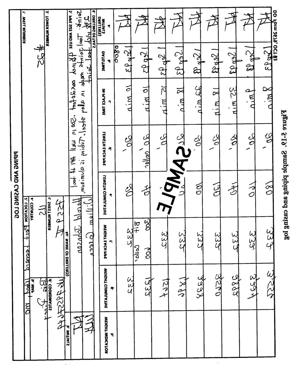
134 5-37
135 5-38


136 Chapter 6 Well-Installation Procedures 6-1. Setting Casing. In rotary-drilled water wells, you can set the casing in the borehole after you finish drilling. However, you must set the casing and grout it near the surface. This prevents the upper portion of the borehole from caving in. For water wells drilled in rock aquifers, you can place the casing through the unconsolidated strata and into the rock to get a tight seal. However, this method does not ensure a tight seal. You can improve the seal by using the following procedures: Step 1. Drill a borehole about 10 feet into the reck. Step 2. Flush the hole with clean water. Step 3. Fill the rock interval with grout, and immediately set the casing into the hole. Let the grout set around the bottom of the casing. Step 4. Drill through the grout, plug in the lower casing, and progess into the aquifer. Step 5. Complete an open-hole well or install a smaller casing and screen inside the outer casing. NOTE: You cannot pour grout through drilling fluid to properly seal the casing Selecting Casing. Well casing is plastic, wrought iron, alloyed or unalloyed steel, or ingot iron. Well-completion kits have either plastic (Figure 6-1) or steel casing. You must know the properties of other casings because you may have to use them. When selecting the casing, consider the stress factor during the installation process, the corrosive element of the water, and the subsurface formation. If you use casings other than those in the well-completion kits, you must specify the weight per foot of pipe you want to use. The tables in A100-66, American Water Works Association Standard for Deep Wells (AWWA), present data on the steel and wrought-iron pipes used as permanent well casings. Joints for permanent casings should have threaded couplings or should be welded or cemented so they are watertight from the bottom of the casing to a point above ground. This precaution will prevent contaminated surface water and groundwater from entering the system. Table 6-1 (page 6-2) lists hole diameters for various sizes and types of well casings. 6-1
137 6-2
138 6-3. Installing Casing. a. Open-Hole Method. With this method, install casing using the following procedures: Step 1. Clean the borehole by allowing the fluid to circulate with the drill bit close to the bottom so cuttings will come to the surface. You may carry the borehole deeper than necessary so that if any material caves in, the material fills the extra space below the casing depth. Step 2. Attach a coupling to the top of the casing. Suspend the casing by either attaching a hoisting plug to the coupling, using a sub (adapter) if necessary, or by placing a casing elevator or a pipe clamp around the casing under the coupling. Step 3. Lower the first length of casing until the coupling, casing elevator, or pipe clamp rests either on the rotary table or on another support placed around the casing. If lifting with a sub, unscrew the sub on the first length of casing and attach it to the second length of casing. If lifting by elevators or pipe clamps, release the elevator bails from the casing in the hole, and attach it to another elevator casing or pipe clamp on the second length of casing. Lift it into position, and screw it into the coupling of the first casing length. (Lightly coat the threads of the casing and coupling with a thin oil. Screw the lengths tightly together to prevent leaking.) Remove the elevator or other support from the casing in the hole and lower the string that is supported by the uppermost coupling. Step 4. Repeat the procedure for each casing length you install. If a cave-in occurs, attach a swivel to the casing with a sub, and circulate the drilling fluid through the casing to flush out the hole and wash the casing down. After the casing is set on the bottom of the hole, drill through the casing into the aquifer. b. Single-String Method With this method, you install the casing and screen (that have been joined) in a single assembly. See paragraph 6-6a (page 6-10) for installation. c. Wash-In Method (Jetted Wells). With this method, you advance the borehole for an expedient jetted-well construction. See paragraph 9-2b(l) (page 9-3) for installation. d. Driven Method (Driven Wells). Install the casing as with the borehole, the cable-tool, or driven-point well method. See paragraph 9-3 (page 9-6) for installation. e. Uncased-Interval Method. In rock, you normally leave the lower portion of the borehole uncased because water emerges from irregular functions in the borehole wall. Therefore, for the well to function properly, you must be careful when locating the bottom of the cased portion in relation to any impermeable zone. Once you establish the depth, drill down and set the casing. Then drill a smaller hole to full depth and proceed with development Grouting and Sealing Casing. Once grout is mixed, it starts to set. Therefore, place the mixture immediately after mixing it. You must have freshly mixed grout continuously to meet requirements. Portland cement meets most grouting requirements. (You can use a quick-hardening cement to save time.) For proper consistency, use no more than 6 gallons of water per 94-pound sack of cement. If you need a large amount of grout, add 1 cubic foot of fine or medium sand for each sack of cement. Add a few pounds of bentonite or hydrated lime per sack of cement for a better flow. For small jobs and if no equipment is available, use a 55-gallon steel drum as a mixing tank. Put 20 to 24 gallons of water in the bard and slowly add 4 bags of cement while stirring or 6-3
139 jetting the water. Use as many mixing barrels as the job requires. If a concrete mixer is available, mix batches and dump them into a storage vat for future use. You can force grout into place using pumps or air or water pressure. In some cases, you can place grout using a dump bailer. If you use the tremie methods, you will need one or more strings of pipe with small diameters. Other equipment you may need to place grout are a mixing tank, hoses, and a feed hopper. a. Dump-Bailer Method. With this method, you can place grout simply and with a minimum amount of equipment. On the dump-bailer, the bottom valve opens and the operator can unload grout at a specified location. This method works best when you need to grout only the lower portion of the casing. Use the following procedures to place grout: Step 1. Run the casing in the hole and mix enough grout to fill the lower 20 to 40 feet of the hole. (A quick method of mixing the grout is to put the required amount of water in a barrel and circulate the water, using a high-pressure jet while adding cement.) Step 2. Place the grout inside the casing with a dump-bailer. Step 3. Lift the string of casing 20 to 40 feet off the bottom, depending on the amount of grout placed. The lower end of the casing should be below the top of the grout. Fill the casing with water and cap the top. Step 4. Lower the casing to the bottom of the hole to force most of the grout up the annular space outside of the casing. Do not uncap the top of the casing until the grout is set. Step 5. Drill through the cement that has hardened in the lower end of the casing and continue drilling to the required depth. (Green cement will increase the viscosity of the drilling mud.) If you anticipate difficulty in filling the casing with water when it is lifted in the borehole, you can add water on top of the grout without lifting the casing. Calculate the volume of grout in the casing. Fill the casing to the top with water. Connect a pump so that you can force in additional water. Pump water into the casing, measuring the volume pumped, until you put in a quantity equal to the volume of grout. This will force all or most of the grout out of the lower end of the casing. You can place a wad of burlap on top of the grout before filling the casing with water to keep the fluids separated. b. Inside-Tremie Method. With this method, you place the grout in the bottom of the hole through a tremie pipe that is set inside the casing (Figure 6-2). The grout will either descend naturally or you may have to pump it through the pipe. Make sure that the tremie pipe is at least 1 inch in diameter. With this method and any other method where you place the grout inside the casing, make sure that water or drilling fluid circulates up and around the casing before you start grouting. To check this, cap the casing and pump in water. If the water comes to the surface outside the casing, you can start grouting. Use the following procedures to complete the tremie method: Step 1. Continue pouring grout until it appears at the surface around the casing. Once the grout reaches the desired depth, it will fill the space around the outside of the casing. Step 2. Suspend the casing about 2 feet above the bottom of the borehole during the operation. Once the grout is in place, lower and seat the casing in a permanent position. 6-4


140 Remove and clean the tremie pipe. The check valve prevents the grout from moving back into the casing. Step 3. The grout should set and harden in about 24 to 72 hours, depending on the cement you use. Drill out the packer and continue drilling the well below the grouted casing. c. Outside-Tremie Method. With this method, you use a tremie pipe to deliver grouting outside the casing. This method is not recommended for depths greater than 100 feet. You can use this method if the space between the casing and the borehole wall is large enough to contain a 1-inch tremie pipe. Use the following procedures to complete grouting using this method Step 1. Lower the pipe to the bottom. Make sure that the lower end of the casing is tightly seated at the bottom of the borehole. Step 2. Mix a sufficient quantity of grout and pump it through the tremie pipe or let it descend naturally (Figure 6-3, page 6-6). As the grout is placed, lift the tremie pipe slowly, but keep the lower end submerged in the grout. 6-5

 when drilling wells using the rotary method. You make the screens by winding triangular sections around a skeleton of longitudinal rods.")

141 Step 3. Fill the casing with water as the grout is placed to balance the fluid pressure inside and outside the casing. Doing so prevents grout from leaking under the bottom of the casing. You can quickly place grout near the surface using a tremie or by dumping the grout in the hole around the casing and puddling it with pipe lengths. However, this procedure only provides a surface seal around the casing and cannot be used as a normal grouting method Selecting Screens. The military uses continuous-slot screens (Figure 6-4) when drilling wells using the rotary method. You make the screens by winding triangular sections around a skeleton of longitudinal rods. Join the triangular sections and rods securely wherever they cress. The screens are constructed of either PVC or stainless steel and are packed in the well-completion kits. Some important factors to remember when selecting screens are that they-- Must produce a sand-free well of less than 2 ppm. Should prevent minimum head loss. Should be of a commercial grade. (Screen sizes are in increments of inch.) Should lend themselves well to development (allow for a two-way flow). 6-6
.")

142 a. Types. (1) PVC Screens. These screens must beat least 8 inches in diameter. Continuous-slot PVC screens are in the 600-foot well-completion kits packed in boxes containing four 20-inch-long sections that can be joined together (Figure 6-5). The kits should contain enough sections to assemble up to 50 feet of continuous-slot, 8- inch well screen. You can use the PVC casings to construct an alternative screen. You saw or mill horizontal slots in sections of the 20-foot-long casing. You cut six rows of slots down the casing. The slots are 1/2 inch apart at a width of inch. You can construct PVC screens in the field by cutting slots in PVC casing with saws. The following lists saws and approximate slot sizes: Hacksaw, about inch. Handsaw, to inch. Circular saw, to inch. These makeshift screens are not as efficient as the continuous-slot screens because of the relatively low open area per foot of screen. However, you should use these screens when the kit contains an insufficient number of continuous-slot screens. The alternative screens are the same as the casing sections. You can place the screens intermittently up the well if you screen more than one aquifer or waterbearing strata. If you screen multiple intervals, you must place gravel packs around the screens and backfilling between the screens. If sufficient gravel-pack material is available, use it continuously to above the top of the screen. (2) Stainless-Steel Screens. These screens are usually 6 inches in diameter and come in 10- and 20-foot sections. You can join the sections to make longer pieces. Most stocked screens have inch openings that are suitable for medium-sand formations. Screens with other slot openings are available and may be needed for special installations. Various end fittings are available so you can use different installation methods. See paragraphs 6-6a through d (pages 6-10 through 6-12) for uses of these end fittings. 6-7

143 (3) Pipe-Base screen. You make this screen by wrapping a trapezoidal-shaped wire around a pipe base that has drilling holes evenly spaced. A pipe-base screen is strong and suitable for deep wells. The screen has two sets of openings. Outer openings are between adjacent turns of the wrapping wire and inner openings are the holes drilled in the pipe base. The percentage of open area per foot of screen (usually low) governs the efficiency of the screen. These screens come in 3- and 4-inch pipe bases for field operations. b. Lengths. Use the electric logging units in the well-completion kits to determine the location, depth, and thickness of an aquifer. Screen length should not exceed the thickness of thin aquifers. You should screen the bottom third of unconfined aquifers and 75 to 80 percent of confined aquifers. However, for interlayered fine and coarse beds, consider the thickness of the coarse strata when determining screen length. Set the screen in the coarse strata. If you have a choice of slot sizes, consider the percentage of the open area or intake area of the well screen to determine length. Use the following calculations to determine the amount of screen to use during drilling operations: (1) Surface Area. SA = π (OD) (12) SA = surface area, in inches per foot. OD = outside diameter of the screen, in inches. (2) Open Area. OA = open area as a percentage. SO = slot opening, in inches. WD = wire diameter, in inches. (3) Total Area. TA = (SA)(OA) TA = total area, in square inches. SA = surface area, in inches per foot. OA = open area, as a percentage. (4) Transmitting Capacity. TC = (TA).31 where- where- where- where- 6-8


144 TC = transmitting capacity, in GPM per foot of screen (based on one-tenth foot per minute of velocity). TA = total area, in square inches. (5) Screen Length. where SL = screen length required, in linear feet. PR = pumping requirement, in GPM. TC = transmitting capacity, in GPM The following example uses the above equations to determine the amount of 12-inch screen required at one-tenth foot per minute of velocity with a slot opening of inch, a wire size of inch, and a pumping requirement of 800 GPM: c. Diameters. The diameter of the well screen usually corresponds to the diameter of the well casing. If you are considering alternative diameters, consider the following: Increasing the screen diameter to increase the yield or capacity of a well. The increase is not proportional. Doubling the diameter of a well screen increases the capacity of the well by about 10 percent. Using a larger diameter screen if the aquifer is thin or the pump is large. Using a long screen with a smaller diameter in a thick aquifer, for better performance. Increasing the length, not the diameter, of the screen to increase the yield of a well in a thick aquifer. d. Slot Sizes. You should understand the function of slot size in well construction. When possible, choose the screen slot size to fit the gradation or grain sizes of the aquifer. Sand and gravel interaction greatly affects the development of the formation around the screen. Small openings limit well yield. Also, small slot sizes produce high velocity in the water passing through the screen. In time, scale or incrustation tends to form on the screen. If the openings are too large, you may have to develop the well more than usual, or you may not be able to clear the well of sand. 6-9


145 Screen slots that are sized to retain the coarsest one-third to one-half of sand or gravel of the aquifer work best in a naturally developed well. About two-thirds of the sand in the layer behind the screen should pass through the slots. A screen set across both coarse and fine strata may need sections with different slot sizes. If you have to pack the screen with gravel artificially, make sure the slot openings correspond to the size of the gravel you use. Screen openings that retain about nine tenths of the gravel work best Installing Screen. You can use several methods to install screens in rotary-drilled wells. To set well screens, you will use the screen hook and casing elevators. You use the hook to engage a bail in the bottom of the screen to suspend the screen on either the sand line or hoist line while lowering the screen into the well (Figure 6-6). Do not pull the screen with the hook after the formation has closed in around the screen. If you are installing a screen using the telescoping method and you must seal the casing, you will need rubber or neoprene packers. All screen-setting methods require accurate and complete measurements of pipe, screen, cable length, and hole depth. a. Single-String Method. With this method, you install the casing and screen as one assembly. Figure 6-7 shows a single-string assembly equipped with fittings for the washdown method. You can omit the washdown fittings if the hole stays open at the bottom. Use the following procedures to install the assembly: Step 1. Attach couplings to the top of the casing and screen section. Install a sand trap to the bottom of the string. Step 2. After running the entire string into the borehole, use casing elevators to carry most of the weight of the string until the formation collapses in around the screen. Step 3. Run the drill pipe inside the casing to the bottom of the screen, and pump water into the well to displace the drilling fluid. Step 4. Raise and lower the drill pipe to wash the full length of the screen. Step 5. Wait for the formation to settle around the screen. Proceed with well completion and development. For deep wells and wells requiring surface casing, you can use the following modified telescoping procedure: Step 1. Grout the surface casing in the borehole before you drill the well to the final depth. Step 2. Use the single-string method inside the surface casing, while bringing the inner casing to the surface. 6-10


146 Step 3. After placing the gravel pack around the screen and impervious backfill on top of the grovel, grout the entire annulus between the inner and outer casing to the surface. A disadvantage of the single-string method is the weight of a long string of casing on top of the screen. When the screen touches bottom, it becomes a loaded column that can easily buckle because of its slenderness. When the screen reaches the correct depth, you can prevent buckling by supporting the screen on casing elevators until the formation material collapses around the screen and supports it laterally. b. Pull-Back Method. This is another method of installing a telescoping screen. Use the following procedures for this method: Step 1. Sink the well casing to the full depth of the well, and clean out the hole to the bottom of the pipe with the bailer. Step 2. Assemble the closed bail plug in the bottom of the screen. screw one or more packers to the top of the bail plug. Step 3. Lower the screen inside the well casing using the sand line. After setting the screen on the bottom, pull the casing back far enough to expose the screen in the aquifer and to a position where the packer is still inside the casing. Step 4. Use a casing ring and slips with two hydraulic jacks to pull the pipe. If the screen moves upward as you pull the pipe, lower the drill bit or other tool inside the screen to hold the screen down. Step 5. Hold the casing with pipe clamps until either the hole caves around the casing and grips the pipe or until you can place grout around the casing and the grout sets, after pulling the casing to its permanent position. Step 6. Bail out the drilling mud so that the sand and gravel of the formation will close in around the screeen. c. Open-Hole Method. Use this method to install telescoping screen when the depth and thickness of the aquifer have been predetermined. Use the following procedures for this method: 6-11
147 Step 1. Sink the well casing into the aquifer to a depth slightly below the desired position from the top of the well screen. Fix the casing in place by grouting or other means. Step 2. Mix drilling mud and fill the casing. Using a bit that will pass through the casing, drill into the aquifer below the casing to make room for the length of well screen to be exposed. Step 3. Lower the screen into position, ensuring that the rubber or neoprene packer remains inside the casing near its lower end when the screen is on bottom. If the hole is too deep, drop gravel into the hole to the correct height. Use the closed bail plug and the packer top-end fittings to support the screen and sand trap (Figure 6-8). With this method, the diameter of the screen must be smaller than the casing, since the hole drilled for the screen will be no larger than the inside diameter of the casing. Also, make sure that the packer fitting at the top of the screen is the proper size to seal inside the casing. The drilling mud must be heavy and thick to prevent the open borehole from caving in, and the mud must be completely removed from the aquifer during development. d. Washdown Method. This method works best if the aquifer is composed of fine to coarse sand with little or no gravel. The screen fittings you need for this method are a washdown or selfclosing bottom. Figure 6-9 shows a fitting you can use when using a telescoping method to set the screen through the casing. Set the casing from the surface to slightly below the depth where you will install the top of the screen. Screw a section of wash pipe into the left-hand female thread of the self-closing bottom and attach the bottom to the screen or sand trap with the wash pipe projecting through the screen. Lift the entire assembly by the wash pipe and lower the screen inside the casing. Add sections of wash pipe until the bottom of the screen is near the lower end of the casing. Use the following procedures for the washdown method: Step 1. Connect the top of the wash pipe to the kelly and start the mud pump. Circulate water (not drilling mud) down the wash pipe. Step 2. Let the screen move down as circulation continues and material washes. Take measurements and stop the descent of the screen when the packer is near the lower end of the casing. If drilling mud is still washing out of the well, continue pumping water until most of the mud is displaced. Step 3. Stop the pump and let the aquifer close in around the screen. When the formation develops friction on the outer surface of the screen, turn the entire string of wash pipe to the right to unscrew the left-hand joint at the bottom. Step 4. When the wash pipe is free, pump in more water. Raise and lower the string several times so that the lower end travels the full length of the screen. This action will wash out more drilling mud and some fine sand from the formation. Step 5. Start development work. Remove the wash pipe and continue the development work. 6-12
 shows an assembled bail-down shoe in the bottom of the screen.")
 shows a shoe with a guide pipe that extends below the screen. Use the following procedures for the bail-down operation: Step 1.")
148 e. Bail-Down Method. With this method, you need special end fittings for the screen. Figure 6-10 (page 6-14) shows an assembled bail-down shoe in the bottom of the screen. The bail-down shoe has a special nipple that has right- and left-hand threads and a coupling with right- and left-hand threads. Figure 6-11 (page 6-14) shows a shoe with a guide pipe that extends below the screen. Use the following procedures for the bail-down operation: Step 1. Start the operation after you sink the well casing to its permanent position. The casing s lower end should be slightly below where you install the top of the screen. 6-13


149 Step 2. Assemble the bail-down shoe, special nipple, and special coupling in the bottom of the screen. Step 3. Screw a length of premeasured pipe into the right-hand half of the special coupling. This pipe, which will extend up through the screen, is called the bailing pipe or conductor pipe. Step 4. Screw one or more packers to the top of the screen. Step 5. Lift the whole assembly by the bailing pipe and lower the screen inside the well casing. Add lengths of bailing pipe as the screen descends until it reaches the bottom of the borehole. Step 6. Mark off the length of the screen on the bailing pipe that projects above the casing, using the top of the casing as the reference measuring point. Run a bailer or sand pump inside the bailing pipe and start bailing sand from below the shoe. 6-14
150 Step 7. As you remove sand from below the shoe by the bailer, the combined weight of the screen and the string of bailing pipe will cause the screen to move downward. Attach additional weights to the bailing pipe, if necessary. Step 8. Monitor the progress of the work carefully, and stop the operation when the screen reaches the desired depth. The packer should be near the lower end of the casing, but still inside the casing. Accurate measurements will avoid sinking the screen too far. Step 9. Drop a weighted and tapered wooden plug (Figure 6-11 ) through the bailing pipe to plug the special nipple on the bail-down shoe. When the plug is in place, unscrew the left-hand threaded joint at the upper end of the nipple by turning the entire string of bailing pipe to the right. Remove the bailing pipe and proceed with well development. If you use a different type of bail-down shoe, the left-hand threaded connection for the bailing pipe may be in the opening in the shoe or it may be in the packer fitting at the top of the screen. In either case, use the same procedures as above for operating the bailing down, plugging the bottom, and removing the bailing pipe. Under certain conditions, you can bail down a well screen without using a bail-down shoe. The bailing pipe is not connected to the screen. You fit the pipe s lower end with a flange or coupling large enough to press on the packer at the top of the screen. The weight of the bailing pipe rests on the screen. You fit the lower end of the screen with an open ring or a short piece of pipe. Be very careful when using this method because the screen is not connected to the bailing pipe and you cannot control the screen s movement from the surface. Careful measurements will prevent sinking the screen too far. This method should be limited to fairly short screens. Plug the bottom of the screen by putting a small bag of dry concrete mix in the bottom and tapping the concrete lightly with the drill bit or other tool Placing Gravel. The most important criteria for grovel pack (artificial sand filters) are comet grain sizes and screen slot opening. Grading should be in proper relation to the grading of the sand in the aquifer. You could have trouble if you use gravel that is too coarse. Coarse, uniformly graded filter sand (about 1/8 inch) makes the best gravel pack for most fine-sand aquifers. You should use fine gravel (1/4-inch maximum size) to pack aquifers consisting of medium or coarse sand. Use a screen with openings that cover about 90 percent of the gravel pack. The following is a field method for producing a filter material or gravel pack from a sand and gravel deposit for a medium sand aquifer. Make two sieves with lumber. Cover one sieve with 1/4- to 3/8-inch hardware cloth. Cover the other sieve with window screen. NOTE: A layer of hardware cloth under the screen provides extra strength to the sieve. Discard all material that will not go through the hardware cloth but that will go through the window screen. Save the materials that the screen retains for analysis and logging purposes. a. Open-Hole Placement. Where drilling mud keeps the borehole open, you can install a gravel pack using the positive-placement method. This method is the most common and best suited to military field operations. Use the following procedures for this placement method: Step 1. Drill a large diameter borehole the full depth of the well. 6-15
151 Step 2. Set a smaller diameter screen and casing centered in the large diameter borehole. NOTE: Basket-type centering guides work best. Step 3. Fill the annular space around the screen with properly graded gravel. Step 4. Fill the borehole with gravel well above the top of the screen. Gravel works downward as sand and silt are removed from the formation around the gravel pack by subsequent development. Development work must be thorough when you drill the borehole using the rotary method because the mud cake on the borehole wall is sandwiched between the gravel pack and the face of the formation. You must break up the mud cake and bring it up through the gravel into the well. Any mud cake not removed reduces the efficiency and yield of the completed well. To ensure that you remove all of the mud cake, limit the thickness of the gravel envelope around the screen to a few inches. A common mistake is to drill a very large borehole and use a small screen, making the gravel too thick for satisfactory results. Another common mistake is to try and place gravel pack into a small annular space, such as 1 inch. The gravel pack usually bridges at a coupling and does not get down around the well screen. A 2-inch annular space is minimum; 3-to 5-inch spaces are best. Remember, the annular space is the difference between the outside of the casing and the wall of the borehole with the casing centered in the hole. In most cases, you must also consider the outside diameter of the couplings. b. Tremie Placement. You can use a tremie pipe when placing gravel-pack materials. The fine and course particles should not separate, as in the open-hole placement, when the aggregate settles through the drilling fluid in the well. Lower a string of 2-inch (or larger) pipe into the annular space between the inner and outer casings. Feed the gravel into the hopper at the top of the pipe. Feed water into the pipe with the gravel to avoid bridging the material in the pipe. The pipe raises as the gravel builds up around the well screen. The tremie system is practical for placing the gravel pack in shallow to moderately deep wells. c. Bail-Down Placement. With this method, you can place a gravel pack as you install the screen. Feed the grovel around the screen, it will go downward with the screen. The bail-down shoe used is somewhat larger than the screen so that gravel being added will follow down and around as the screen sinks in the formation. Figure 6-12 shows this operation. Development work is an essential part of this method. Screen openings must be larger than the grain size of the aquifer so enough aquifer sand will pass through and the gravel pack will replace the sand around the screen. d. Double-Casing Placement. With this method, you place gravel and use a temporary outer casing (Figure 6-13, page 6-18). With this method, you pull back the casing as you pour gravel into the space. This method is somewhat similar to pull-back screen installation Using Alternative Methods. a. Formation Stabilizer. When you do not use a grovel pack you can place formation-stabilizer material to help prevent deterioration of the annular space outside the screen. Fine, loose strata may cave into that space, enter the screened interval, and degrade the well. The decision to use this material usually occurs during the well-construction process. In unstable formations, consider stabilizing wherever the annular space is more than 2 inches thick. 6-16

152 Grain size is important since you will develop the aquifer naturally, and as much as half of the stabilizing material could flow through the screen. The grain size should average slightly coarser than that of the aquifer and should be well distributed. Widely used formation stabilize are 6-16
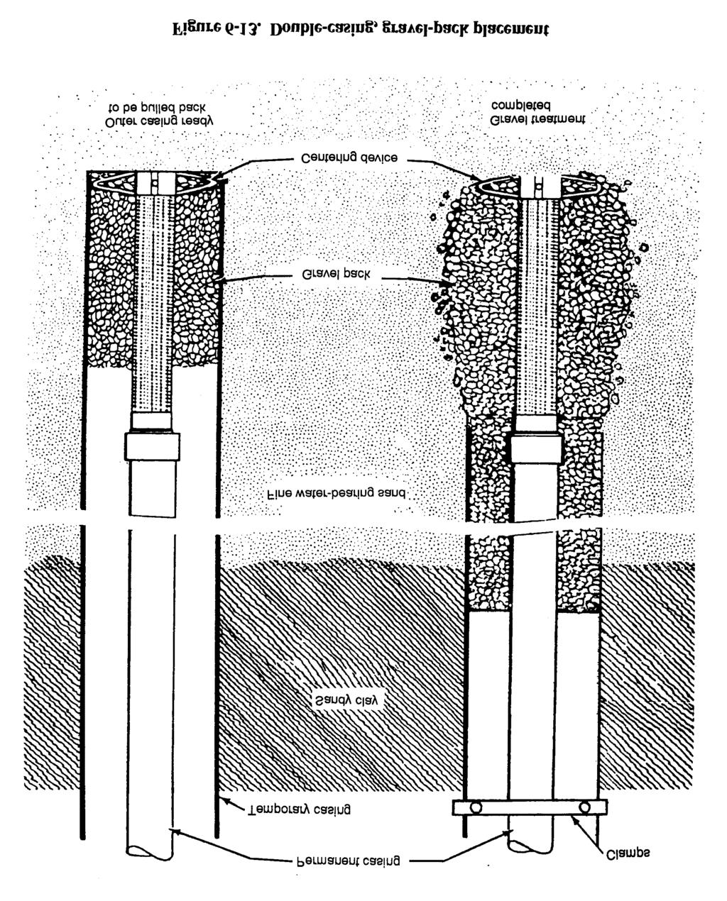
153 6-18
154 Step 1. Center the screen at its final position in the open section of the borehole, using a centralizer if needed. Step 2. Place the stabilizer material by dumping and tamping it down the hole or by using a tremie. Raise the level of stabilizing material above the top of the screen and add additional material as development progresses. Step 3. As you develop the well, the level of the stabilizing material drops as the material is pulled into the screen. You must replace this material to maintain the level above the top of the screen. b. Unscreened Well. In competent rock, you usually tap the aquifer through numerous, irregularly spaced fractures. Once cleared of mud and rock fragments, the fracture stay open and the intake interval functions efficiently for a longtime. You should not need a screen in such a rock well. If you anticipate an unscreened-well design, you must be particularly attentive to the location of the top of the unscreened intake interval and its relation to the position and thickness of any impermeable layer. 6-19

 to the bottom of the drill string (Figure 7-l). Step 2. Use the string to lower this tool into the screen. Step 3.")
155 Chapter 7 Well-Completion Procedures This Chapter implements STANAG 2885 ENGR Well Development. Table 7-1 shows the different well-development methods and some characteristics of each method. All methods are designed to produce a stable flow condition. Be careful not to let the drill strike the bottom plug during well development, especially when using PVC pipe. a. Jetting Method. With this method, you use a jetting tool that you lower inside the screen. Use the following procedures for this method: Step 1. Attach the jetting tool (in the well-completion kit) to the bottom of the drill string (Figure 7-l). Step 2. Use the string to lower this tool into the screen. Step 3. Connect the upper end of the pipe to the kelly or the discharge side of the mud pump. Step 4. Pump water into the screen and rotate the jetting tool slowly so that the horizontal jets of water wash out through the screen openings. Step 5. Raise the string of pipe gradually and continue rotating to backwash the entire surface of the screen. If possible, use a pump pressure of 100 psi. This backwashing method is effective in removing caked drilling mud from the borehole wall. A disadvantage in military field operations is that this method requires a large supply of water. After covering the entire screen with the jetting tool, remove the tool. Remove the sand that has collected in the sand trap with a bailer. Repeat this process until the well stops producing sand. If a significant volume of material is removed during 7-1
156 development, you should add more filter material around the screen to keep the top of the grovel pack above the top of the screen. b. Pump-Surge Method. This backwashing technique involves alternately pumping water to the surface and letting the water run back into the well through the pump-column pipe. Use an airlift pump or a deep-well turbine pump without a foot valve. See Chapter 4 for discussions on pumps. Do not use the permanent well pump for development. Pumping sand could damage the pump. Use the following procedure for this method: Step 1. Start the pump. As water comes to the surface, stop the pump to release the water. The power unit and starting equipment determine the starting and stopping action of the pump. The effect is to lower and raise the water level in the well intermittently through the screen openings. Periodically, pump the well to remove the sand brought in by surging. Step 2. Remove the pump and bail out the material in the sand trap, after surging. Step 3. Repeat the process until the well stops producing sand. c. Gravity-Outflow Method. Backwashing by gravity outflow involves pouring water into the well rapidly to produce outflow through the screen openings. Inflow through the screen is then produced by bailing water from the well rapidly. This is a slow surging technique requiring several minutes to complete a cycle. If the static water level is high enough to permit pumping b y suction lift, you can use a small centrifugal pump instead of the bailer to speed up the work. If there is room in the well casing, connect the discharge side of the pump to a string of small diameter pipe that is lowered into the well. The water added is pumped down inside the screen, creating a turbulence that will help to develop the formation. d. Pressure-Pumping Method. Occasionally, wells are backwashes by capping the casing and pumping water into the well under pressure. Water is forced outward through screen openings similar to the closed-well method of using compressed air for development (paragraph 7-1f(2), page 7-5). Pressure pumping is an inefficient method because the desirable surging effect is difficult to produce. You must make sure to seal the casing tightly in the borehole and prevent water from being forced up around the outside of the casing. e. Surge-Block Method. With this method, water is surged up and down in the casing with a surge block or plunger. A surge block can be a solid plunger or swab or a plunger equipped with or without a valve opening (Figure 7-2). The valve-type plunger gives a lighter surging action than the solid type. Light surging is advantageous in developing tight formations. Therefore, start the surging process slowly and increase the force as the development proceeds. Be careful when working with wells using PVC pipe. The casing or well screen could collapse from vigorous surging action. Plugging the valve of the plunger changes it to a solid-type plunger that you can use when you need greater surging force. Attach sufficient weight to the surge plunger to make it fall with the same speed on the downstroke as the drilling machine uses on the upstroke. The drill stem provides the weight required for the surge block. Use the following procedures for the surge-block method: Step 1. Lower the surge plunger into the well until it is in the water above the top of the screen. Keep the plunger a few feet above the screen so that it will not strike the screen while surging. 7-2

157 Step 2. Start surging slowly and gradually increase the speed until the surge plunger rises and falls without slack. With a rotary rig, lift the plunger 3 or 4 feet before dropping it. When using the sand line, control movement by using the hoist brake and clutch. Step 3. Continue surging for several minutes. Pull the plunger out of the well and lower the bailer or sand pump into the screen. When the bailer rests on the sand that has been pulled into the screen, check the depth of the sand by measuring on the sand line. Bail all the sand out of the screen. Step 4. Repeat the surging operation and compare the quantity of sand with the first quantity. Bailout the sand. Step 5. Repeat surging and bailing until little or no sand can be pulled into the well. Lengthen the period of surging as the quantity of sand removed decreases. f. Compressed-Air Methods. Compressed air provides rapid and effective development of wells, using an open- or closed-well method. You can use the standard 350-cfm compressor for developing most wells at a pressure of at least 100 psi. However, a higher pressure is preferable. The 250-cfm compressor will pump water by air lift from 100 to 150 GPM, depending on the submergence and size of the pipes you use. Table 7-2 (page 7-4) shows the recommended sizes of pipe and air lines and the pumping rates you should use for various sizes of wells. (1) Open-Well Method. The surging cycle is established by pumping from the well with an air lift and by dropping the air pipe suddenly to cut off the pumping. This cycle discharges large bubbles of compressed air into the screen. The submergence ratio must be 60 percent. Submergence is the extent to which the air pipe is submerged in the water compared to the extent the pipe is between water and ground level. Work efficiency decreases rapidly as the submergence ratio drops below 60 percent. In deep wells with a considerable head and a low submergence ratio, you can perform some effective work by shooting heads. 7-3
158 Figure 7-3 shows the proper method of placing the drop pipe and airline in the well. Use a hoist line to easily handle the drop pipe. Suspend the air pipe on the sand line. Fit a T at the top of the drop pipe with a short discharge pipe at the side outlet. Wrap a sack around the air line where it enters the drop pipe to keep water from spraying around the top of the well. Discharge from the compressed air tank to the well should be the same size as or one size larger than the airline in the well. Connect a quick-opening valve in the line near the tank. You need a pressure hose, 15 feet long (minimum), for moving the drop pipe and air line up and down. Use the following procedures to start developing the well using this method: Step 1. Lower the drop pipe to within 2 feet of the bottom of the screen. Place the air line inside the drop pipe with its lower end 1 foot or more above the bottom of the drop line. Step 2. Let air enter into the airline and pump the well until the water appears to be free of sand. Start slowly. If all the water is suddenly removed, the casing may collapse in deeper wells, especially when using PVC pipe. Step 3. Close the valve between the tank and airline and pump the tank full of air to a pressure of 100 to 150 psi. Step 4. Lower the air line until it is about 1 foot below the drop pipe. Open the quick-opening valve so the air in the tank can rush with great force into the well. A brief, forceful head of water will emerge or shoot from the casing and from the drop pipe. Step 5. Pull the airline back into the drop pipe immediately after the first heavy load of air shoots into the well. Doing so will cause a revered of flow in the drop pipe that will effectively agitate the aquifer. Step 6. Let the well pump as an air lift for a short time and then shoot another head. Step 7. Repeat this process until no sand shows, indicating the completion of this stage of development. Step 8. Lift the drop pipe to a position 2 or 3 feet higher in the screen and follow the same procedure. This develops the entire length of the screen a few feet at a time. Step 9. Return the drop pipe to its original position and shoot one or two more heads. Step 10. To complete the development process and thoroughly clean out any loose sand, pull the air line up into the drop pipe and use it as an air lift to pump the well. 7-4

159 (2) Closed-Well Method. With this method, you use compressed air to close the top of the well with a cap and arrange the equipment so air pressure can build up inside the casing to force water out through the screen openings (Figure 7-4, page 7-6). 7-5

160 Disadvantages with this method are-- That valves and fittings may not be available for military field operations. The danger of forcing water upward outside of the casing. This will loosen the casing and could ruin the well by bringing clay down into the formation. 7-6
161 Use the following procedures to develop a well using this method: Step 1. Arrange the equipment as in Figure 7-4, and turn the three-way valve to deliver air down the air line, preferably with the air cock open. This will pump water out of the well through the discharge pipe. Step 2. When clear water emerges, cut off the air and let the water in the well regain its static level. Step 3. Listen to the air escaping through the air cock as the water rises in the casing to determine stability. Close the air cock and turn the three-way valve to direct the air supply down the bypass to the top of the well, forcing the water out of the casing and back through the screen. This technique will agitate the sand and break down any bridging of the sand grains. When the water has been pushed to the bottom of the drop pipe, air escapes through the drop line. You can prevent air logging of the formation by keeping the drop pipe above the well screen. Step 4. Cut off the air supply and reopen the air cock so the water can reach the correct static level when you hear the air escaping from the discharge pipe or when the pressure stops increasing. Step 5. Turn the three-way valve and direct the air supply down the airline to pump the well. Step 6. Repeat this process until the well is thoroughly developed. You should not have to bail the well after developing it because the water velocity usually cleans out the sand from the well. However, if you did not initially bail the well thoroughly, you may have to repeat the bailing process to clean out the well Dispersion Treatment. Dispersing agents, mainly polyphosphates, when added to drilling fluid, backwashing, jetting water, or water standing in the well, counteract the tendency of mud to stick to sand grains. These agents are procured locally on an as-need basis. Baroid Industries produces Barafos, a white, granular, sodium tetraphosphate thinner and dispersant. You may use chemicals such as sodium hexametaphosphate, tetra sodium pyrophosphate, sodium tripolyphosphate, and sodium septaphosphate to develop wells. Dispersants work effectively when applied at the rate of one-half pound of chemical to 100 gallons of water in the well. Let the mixture stand for about one hour before starting well development. Wetting agents, such as CON DET, increase the dispersion action of polyphosphates when added to the solution at a ratio of 1:100. Be careful when using the dispersion process because you could have an adverse reaction. The driller should make the decision to use or not to use dispersants Rock Development. Use this method to develop wells in rock formations. You can obtain good results by combining jetting with air-lift pumping from a limited zone isolated by inflatable packers. The objective is always to wash out fine cuttings, silt, and clay that have worked into the fissures, crevices, or pores of the rock during the drilling operations. Openings that remain plugged reduce water flow into the well. Develop the well thoroughly to remove all obstructing material. When drilling through limestone formations, use acid to dissolve lime-like cementing material and to open up connections with joints or fissures beyond the borehole wall. However, such operations are rare in military well drilling. 7-7
162 7-4. Well Protection and Treatment a. External Preparations. You should disinfect and protect a well before starting the borehole. Some other preventive measures are-- Stopping surface contaminants from entering the well. Ensuring that the drilling water s quality is suitable. Cleaning and disinfecting all drilling equipment before starting a new well. Disinfecting the water used for drilling if you use a mud-based drilling fluid. If you use a synthetic drilling fluid, chlorinate the fluid. However, doing so will break down the fluid and reduce its life. Circumventing possible water-quality problems by stopping potentially harmful fittings and equipment from entering the borehole. Carefully check the list of the hardware and materials placed and left in the well. NOTE: Well casings should extend no more than 12 inches above the pump-house floor on a finalgrade elevation and not less than 12 inches above the normal anticipated flood level. b. Sealing Casing. A well must be carefully protected from sewage and other contaminants that could migrate down the well column to the aquifer and well screen. Sources of pollution could be on the surface or in shallow perched water, unusable aquifers, and intermittently saturated beds. Carefully planning the well s location could help avoid the surface sources. However, you may not know about subsurface contaminants until you start drilling the well. If that occurs, you will have to alter plans and seal the well quickly. Chapter 6 discusses sealing or grouting operations. See STANAG 2885 ENGR (Edition 2) for sealing a NATO well. A rock well may be grouted from the lower end of the casing to the surface. You can place grout between the inner and outer casings and around the inner casing in a portion of the drilled borehole below the outer casing. Make sure that overburden does not seal the borehole after you set the casing. c. Disinfection. All newly constructed wells should be considered contaminated from the construction process and disinfected immediately after completion. Well-completion kits provide packages of a dry chlorinator for breaking down synthetic drilling fluids to disinfect the wells. Prepare a chlorine solution by-- Mixing 1 heaping tablespoon of calcium hypochlorite with water to make a thin paste. Break up all lumps. Stirring mixture into 1 quart of water. Let the mixture stand a short time. Pouring off the clear liquid. The chlorine strength of the solution is about 1 percent. One quart of the liquid is enough to disinfect 1,000 gallons of water. Larger quantities of the solution may be prepared in the same proportion and, if placed in sealed containers (preferably glass), can be stored for several years without losing its effectiveness. Estimate the volume of water standing in the well. Pour in the corresponding ratio of solution to gallons of water in the well. (For safety, use less solution than too much solution.) Agitate the 7-8

163 water in the well thoroughly and let it stand for several hours, preferably overnight. Flush the well to remove all of the disinfecting agent. You can disinfect the well casing by returning water to the well during the early stage of flushing and washing the walls with chlorinated water. d. Cathodic Protection. A sacrificial anode (Figure 7-5) is the simplest method of protecting metal casing from corrosion. Connect a galvanically active metal bar, such as magnesium-coated wire, to the casing. Bury the anode bar near the casing below the water table. In this cell, ions flow to the casing through the groundwater. While the anode corrodes, the casing remains unaffected. Another method is to suspend cable (acting as the anode) into the well. The anode continues to operate and protect the casing until it is consumed. (Periodically replace the anodes as continuing maintenance.) e. Well Head and Collar. Use the well head in the well-completion kit; otherwise, extend the casing at least 1 foot above the general level of the surrounding surface. Seal the space around the outside of the casing by pouring a concrete platform around the casing at the surface (Figure 7-6, page 7-10). To form a concrete platform, you will need the following bill of materials (BOM): Two 2-inch by 10-inch by 8-foot boards. Cut these in half for the walls. Eight 2-foot long No. 4 reinforcement bars for the comer stakes. One 4- by 4-foot wire mesh. About 0.5 cubic yard of concrete. Use the following procedures to make the platform: Step 1. Step 2. Step 3. Step 4. Step 5. Step 6. Step 7. Clear the site with shovels. Dig a 4-inch excavation. Construct the form. Place the wire mesh, snipping out the center for the casing pipe. Mix and pour the concrete quickly. Pull the wire mesh up through the concrete. Screed with a 2-inch by 4-inch by 8-foot board. If you do not have a container to mix the concrete, construct a mortar box using the following materials: One 4-foot by 8-foot by l/2-inch piece of plywood for the base. Four 2-inch by 6-inch by 8-foot boards for the walls. One 2-inch by 4-inch by 8-foot screed beam. 7-9


164 NOTE: When mixing concrete, add the water slowly. Use 5 gallons of water per sack of concrete. Mix it with a hoe and place the concrete quickly. The upper surface of this slab and its immediate surroundings should be gently sloping so water will drain away from the well. You should also place a drain around the outer edge of the slab and extend it to a discharge point that is far away from the well. A well with pipe casing should have a sanitary seal at the top that fills the space between the pump pipe and the well casing. This device consists of a bushing or packing gland that makes a watertight connection Well-Completion Report. Figure 7-7 (pages 7-11 and 7-12) is an example of a military water well completion summary report (DD Form 2680). This form is used to update the world-wide resource data base. After you complete all well-drilling operations, fill out the form and send to the address on the form. DD Form 2680 is in the back of this manual for reproduction and use. 7-10


165 7-11 FM 5-484/NAVFAC P-1065/AFMAN
166 7-12
167 Chapter 8 Well-Performance Testing Procedures 8-1. Testing Pumps. You will normally use the permanent pump for pump testing. If you use a temporary unit, it must be adequate to draw down the water and hold it at a prescribed flow rate for a period of hours. This test will determine the specific capacity of the well. You can estimate the yield of a small well by bailing water from the well rapidly if no pump is available. You must know the bailer s volume and count the number of times per minute the bailer is brought up full to estimate the GPM of the well. Accurately measuring drawdown is not possible during the test because the water level constantly fluctuates. a. Permanent Wells. You should use two different testing procedures when a pump is available, depending on the intended use of the well and the available testing time. If the well will be a permanent installation and maintained in the future, you should conduct a detailed test. Measure the static water level in the well before testing, and measure the drawdown during the test. Conduct the test as follows: Pump at a rate that will lower the water in the well about one-third of the maximum drawdown possible (one-third the distance from the static water level to the top of the well screen) or about one-third of the rated capacity of the pump. Monitor and adjust the flow rate early in the test because as the drawdown increases the flow rate decreases. Continue pumping at a constant flow rate until the drawdown remains constant (about 1 to 4 hours). Record the flow rate, drawdown, and testing time. Initially, take readings rapidly, and then spread out the readings as the test continues. A reading schedule that doubles the time between readings is preferable. The recommended schedule is as follows: 0 (at the start of the test) 30 seconds, 1 minute, 2 minutes, 4 minutes, 8 minutes, 15 minutes, 30 minutes, 1 hour, 2 hours, 4 hours, and so forth. Establish the desired, constant flow rate quickly. You must record the exact time of each reading (not the intended or scheduled time). After the drawdown stabilizes (1 to 4 hours), the pumping rate should increase to a new, constant flow rate, which will produce two-thirds of the capacity of the pump. Do not stop the pump between these test segments. Repeat the measurements, noting the exact time that the new flow rate was started. Try to follow the above reading schedule, starting from the time the flow rate was increased. When the drawdown stabilizes, increase the pumping rate to produce the maximum drawdown or about 90 percent of the maximum capacity of the pump. Conduct another reading schedule until the pumping level stabilizes. You may modify the above procedure depending on well requirements and local site conditions. You should not modify the precision and accuracy of the measurements taken. Test results should become a part of the permanent records. The results are useful for evaluating the efficiency of the well in the future and for determining the need for well rehabilitation. Calculating the GPM per 8-1

168 foot of drawdown gives the capacity of the well. You can use this information to estimate production and to regulate the pump s flow rate to prevent dewatering of the well and possible pump damage. b. Temporary Wells. Conduct a single-stage test rather than the step drawdown test. To establish the flow rate, conduct a 1- to 2-minute test to determine the GPM per foot of drawdown. Let the well return to the original static water level before testing (about 1 hour). Select a flow rate that will produce about two-thirds of the available drawdown but will not reach more than 90 percent of the pump s capacity. Conduct the test as described above, but with only one segment. When the drawdown stabilizes for the selected flow rate, stop the test. c. Methods. See Chapter 4 for a description of pumps used in testing and well production. (1) Submersible-Pump Method. Use the submersible pump in well-completion kits to pump test the water well. Set the pump deep enough to attain the maximum pumping rate and drawdown. When testing a well with a screen, set the suction of the pump above the top of the screen to prevent lowering the water level below the screen. When testing a well without a screen, try not to dewater the production part of the aquifer. For proper testing, you must have a reliable power source so that testing will not be interrupted. The power must be sufficient to drive the pump at a rated speed so that full capacity can be developed. (2) Air-Lift Method. This method is sometimes best for military field operations, especially if the well may produce sand that could damage or reduce the life of a submersible pump. An air-lift pump has two major problems. Air turbulence could make drawdown measuring difficult, and entrained air may cause considerable error in measuring the flow rate. After constructing an air-lift pump, check the pump capacity against the expected well yield. To conduct the test, set the pump according to the readings in Table 4-2 (page 4-13). An air compressor that puts out 350 cfm at 200 psi is suitable for performing most air-lift pumping operations. To determine the amount of air needed for pumping water, use the following equation or refer to Figure 8-1. where V = h = log = H = C = free air (actual) required to raise one gallon of water, in cubic feet. total lift, in feet. logarithm-c value. operating submergence, in feet. constant (Table 8-1). 8-2


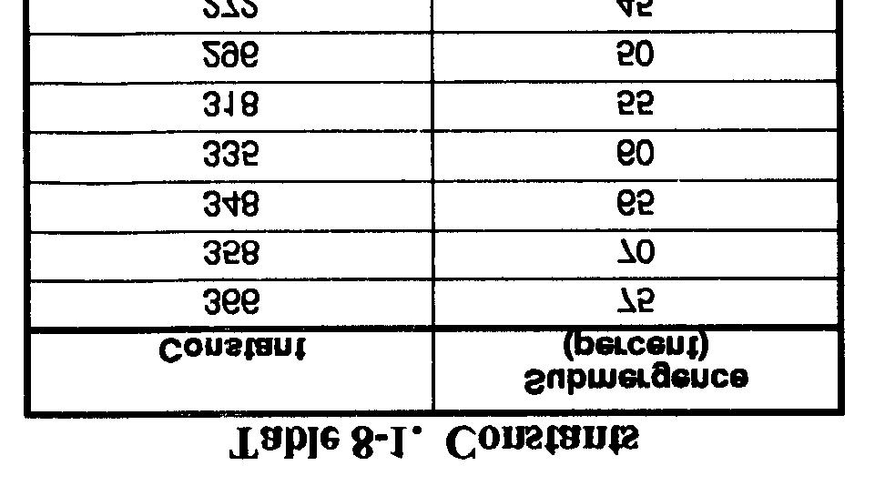

169 8-3 FM 5-484/NAVFAC P-1065/AFMAN

 to obtain flow-rote measurements. 8-2. Measuring Water Level. a. Electric-Line Method.")
170 The pressure required to start pumping will be equal to the depth of water over the submerged end of the air pipe. After pumping has started, the water in the well will draw down to a working level. The air pressure required will be the total lift, in feet, from the working water level plus the friction loss in the airline. Conduct the test and try to measure flow rate and drawdown quickly. Pumping creates turbulance in the well. Use the air-line method (paragraph 8-2c) to try and measure drawdown. Because of entrained air, use the measured-container method (paragraph 8-3a) to obtain flow-rote measurements Measuring Water Level. a. Electric-Line Method. Water levels can be measured accurately with a two-conductor, battery-powered indicator known as an M-Scope (Figure 8-2). Well-completion kits usually contain an M-Scope. The M-Scope is a battery and a meter connected in series. When the upper wire on the tip of the M-Scope in the well touches the water, the circuit is completed and the meter gives a steady reading. Measure the amount of wire in the well to determine the depth to the water level. The wire is marked at 5-foot intervals for easy measuring. b. Tape Method. Use this method to measure the depth to the static level in a shallow well. Conduct this test as follows: Chalk one end of a weighted steel tape with carpenter s chalk. Lower the tape (Figure 8-3) into the well to a depth of 1 or 2 feet past the chalk. (You can use soluble felt-tip markers as an alternative to chalk.) Measure the wetted length of the tape and subtract the amount from the total length lowered below the reference point to obtain the water depth. This test is accurate to within 0.01 foot. c. Air-Line Method. You can measure the water level with an air line to follow drawdown and confirm a stable head during a test (Figure 8-4, page 8-6). The air line is usually 1/8- or l/4-inch copper tubing or galvanized pipe that is long enough to extend below the lowest water level you are measuring. Fasten the air line to the pump bowls or cylinder. Install the airline with the pump. The pipe must be airtight; makeup all joints carefully. Measure the vertical length of the airline from the pressure gauge to the bottom of the line at the time of installation. 8-4


171 Attach a pressure gauge to the airline at the surface with an ordinary tire valve so you can pump air into the line. Pump air into the line until you get a maximum reading. The reading should be equal to the pressure exerted by the column of water standing outside of the airline. Subtract the reading from the total vertical length of air line to get the depth to the water below the center of the gauge. Readings are measured in feet, so you may have to convert your figures Measuring Discharge Rate. a. Measured-Container Method. You can determine the flow rate from a well or pump by measuring the time required to fill a container with a known volume. With this method, use small containers for early measurements and large containers for later measurements. Also, use an instrument, such as a stop watch, for accurate time measurements. Use the following equation: where FR = flow rate, in GPM. v = volume, in gallons. T = time required to fill container, in seconds. b. Flow-Meter Method. A turbine-type flow meter will give an acceptable flow-rote reading. These meters are used by civilians. You can also use a totalizer-type water meter when the yield is low. Use these meters to measure the total gallons pumped and determine the flow rate. To do this, record the number of gallons that have flowed within a set amount of time and compute the flow rate. c. Circular-Orifice Method. A circular-orifice meter (Figure 8-5, page 8-7) is a device you can make to measure discharge rates. This device gives good results and is compact and easily installed. The meter consists of a sharp-edged circular orifice at the end of a horizontal discharge pipe. The orifice is from one-half to three-fourths the diameter of the pipe. The inside of the pipe must be smooth and free from obstructions for a length of 6 feet from the orifice. The discharge pipe has a small hole on one side with a rubber-tube connection. The pipe is designed so that you can measure the pressure (head) in the discharge pipe at a distance of 2 feet from the orifice. 8-5

172 The length of hose and ruler depends on the pipe size you use (Table 8-2). The discharge pipe must be horizontal, and the stream must fall free from the orifice. The orifice must be vertical and centered in the discharge pipe. The combination of pipe and orifice diameters for a given test should be such that the head measured will be at least three times the diameter of the orifice. d. Open-Pipe Method. With this method, the pipe is fully open and you measure the distance the water stream travels parallel to the pipe at a 12-inch vertical drop (Figure 8-6, page 8-8). Use the following procedure: 8-6


173 Step 1. Measure the inside diameter of the pipe and the distance the stream travels parallel to the pipe at a 12-inch vertical drop. Your results will be in inches. Step 2. Estimate the flow from the pipe diameter and the distance the stream travels (Table 8-3, page 8-8). Your results will be in GPM. For partially filled pipes, measure either the water depth or the freeboard. Divide the diameter by the water depth to get a percentage ratio. Measure the stream as above and calculate the discharge. The actual discharge will be, approximately, the value for a full pipe of the same diameter multiplied by the correction factor from Table 8-4 (page 8-8). 8-7
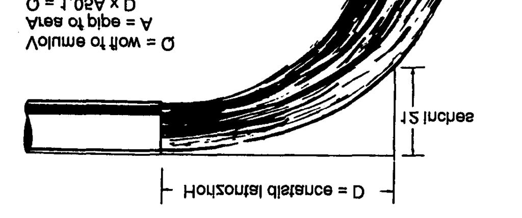
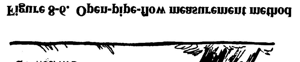
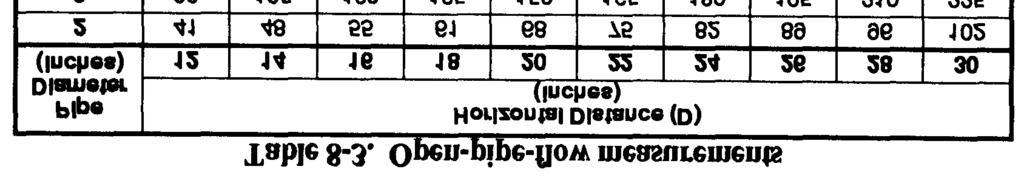
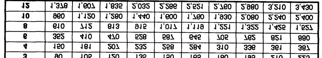
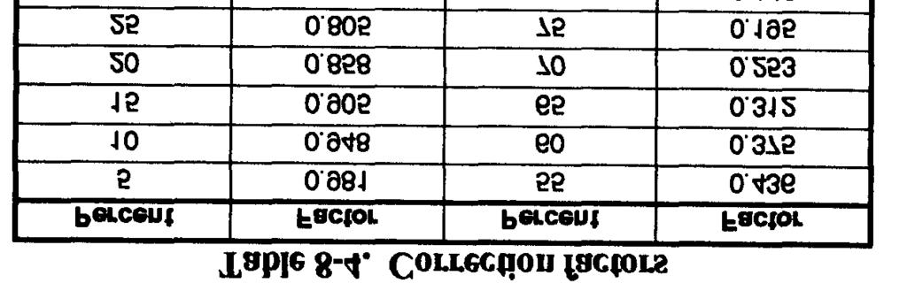
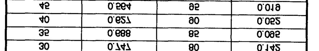
174 8-8


175 Part Three. Special Considerations Chapter 9 Alternative Well Construction 9-1. Fundamentals. Under special conditions, methods other than the rotary and down-hole hammer may be more expedient for well drilling. Conditions favoring less standard methods include the following: Availability of local, nonstandard drilling equipment and qualified personnel. A shallow aquifer that can be developed quickly without mobilization delays. Availability of unskilled personnel only. Requirements for a small water supply Jetted Wells. In the jetting method, you dig a borehole using a high velocity stream of water. The stream loosens the soil and washes the fine particles up and out of the borehole. The jetting method is particularly successful in sandy soils when the water table is close to the surface. Jetting is simple and dependable, and you use hand tools rather than bulky drilling equipment. Two jetting procedures are available washing in a casing or sinking a self-jetting well point. With the jetting method, you can sample the general character of a formation by examining the cuttings brought to the surface in the return flow. a. Equipment. (1) Swivel. The water swivel must be able to carry the weight of the drill pipe and must sustain the maximum pressure delivered by the pump. Figure 9-1 shows a connection that you may use at the top of small-diameter jetting pipes in place of a swivel. (2) Drive Weight. This is weight you drop on the pipe to help penetrate clayey or semifirm soil. (3) Jetting Fluid. Water is commonly used in jetting, but a fluid with greater viscosity and weight may be prepared with clay or commercial bentonite. However, a heavier fluid tends to seal the borehole wall, preventing water penetration. In the jetting process, fluid is led from the borehole to a pit where cuttings settle to the bottom. The jetting pump then recirculates this fluid. Under certain conditions in the Arctic, steam is used to construct jetted wells. 9-1


. (5) Pump.")


176 (4) Hoist. You need a hoist to handle the drill pipe and casing. You may use hand-operated equipment such as a tripod with tackle. If available, you should use a percussion-type drilling rig with a power hoist (Figure 9-2). (5) Pump. A pump with suitable hose connection able to deliver 50 to 100 GPM at 50 psi is adequate. The quantity of water needed to jet a well varies with the type of sediment being penetrated. Sand requires the most water; however, high pressure is not necessary. A nozzle pressure of 40 psi is usually sufficient. Clay and hardpan require less water. However, they are not 9-2
177 readily displaced except by a small cutting stream delivered at high pressure. You can get a pressure of 200 psi from small nozzles in the drill bit. (6) Bits. In soft soil, you may use a paddy or expansion bit to make a hole that is slightly larger than the casing. Use the percussion method with a hand rig and straight bits to penetrate hard layers. Use drill-like bits with heavier rigs to penetrate hard layers that do not yield to the water jet. See Figure 9-3 for bits used in jetting. b. Methods. (1) Wash-In. Before washing the casing into the hole, cut the lower end of the casing to form a toothed cutting head (Figure 9-4, page 9-4). Normally, four to six l-inch long (minimum) teeth are sufficient. Use the following steps to complete the wash-in method: Step 1. Mark the outlines of the teeth on the casing using a power drill or cutting torch. Drill or cut holes in the casing to form the gullets of the teeth. 9-3


178 Step 2. Cut the sides of the teeth with a hacksaw or an oxyacetylene torch to meet the outside circumference of the drilled holes. Rounded holes are desirable so the teeth can readily clear themselves of gravel or other material. Bend half the teeth outward so they cut a hole slightly larger than the casing. Step 3. Place a capon the top of the casing, and attach the discharge hose from the pump to the connection provided in the top of the cap. Suspend the casing vertically, using a hoist. Lay the cutting head on the ground, preferably in a shallow, hand-dug hole. The majority of the casing s weight should rest on the ground. Step 4. Operate the jetting pump at full capacity. The casing will fill with water and begin to sink by its own weight as the ground is washed out from under it. The hoist must keep sufficient tension on the casing to hold it vertical. If resistance stops the downward movement of the casing, lift it up 2 or 3 feet and then drop the casing. Step 5. Use chain tongs or wrenches to rotate the casing so the teeth at the lower end will cut into the bottom of the borehole. If you wash in more than one length of casing, keep the borehole and first length of casing full of water while attaching the second pipe length and connecting the pump to the pipe. Doing so maintains fluid pressure against the borehole wall and should prevent caving. Step 6. Stop the pump, and remove the cap at the top of the casing when the casing reaches the desired depth. If the casing is permanent, telescope a well semen through the casing until it rests on the bottom of the well. Pull the casing up until the screen is exposed to the aquifer and cut the casing off at a point about 1 foot above the ground surface. If the casing is temporary, attach a well pipe to the screen before lowering it into the casing. When the screen is resting on the bottom of the borehole, pull the entire casing out of the borehole. You can reuse this casing. (2) Self-Jetting. Figure 9-5 shows the well-point types needed in self-jetting. The continuous slot has a semen constructed of a narrow ribbon of metal wound spirally around a skeleton of longitudinal rods. The brass jacket consists of a woven wire gauze wrapped around a perforated pipe and covered with perforated brass sheet. The jetting head contains a spring-loaded disk or balltype valve that opens when water is forced through during the jetting operation. The valve closes automatically when jetting stops or the well is completed and pumping begins. 9-4


179 FM 5-48/NAVFAC P-1065/AFMAN Use the following steps for the self-jetting method: Step 1. Couple the well point to the bottom of the riser or well pipe. Attach the swivel to the other end of the well pipe. Connect the discharge hose of the pump to the swivel, and dig a shallow hole. Step 2. Upend the well-point assembly with the well point standing vertically in the hole. Start the pump and partially open the discharge valve. The jet of water will displace the self-closing valve in the well point and flow through the openings in the head. The soil is washed from under the well point, allowing the point to sink into the ground. Using an up-and down movement of the well-point assembly will speed penetration. Step 3. Increase the water flow by opening the pump discharge valve more as jetting continues. Inmost sands, a pressure of 40 psi at the well-point nozzle will displace soil readily. You may need pressures of 100 to 150 psi to move gravel or penetrate clay. If a regular jetting pump is not available, two standard centrifugal pumps operating in series may work satisfactorily. Step 4. Remove the hose from the riser pipe, and couple the pipe to the suction side of the pump after sinking the well point to the desired depth. Step 5. Develop the well by quickly opening and closing the discharge valve while operating the pump at a moderate speed. Continue this operation until you clean out all of the fine material from the well-point screen. 9-5
180 (3) Casing and Completion. Jetting fluid effectively prevents caving or collapse of the drilled hole. Insert the casing in a single string only after jetting reaches the full depth. If you do so before, the casing sinks as fast as jetting proceeds. If you encounter too much resistance, you may have to force the casing down. For depths of 200 to 300 feet, you can use a casing of 4-inch diameter pipe. If you sink a deeper well, place a smaller string (3-inch diameter pipe) inside the first string. To complete the jetted well, connect a hose to the exposed end of the well pipe and couple it to the pump intake. The well will yield water immediately if the pump is in good condition and you have properly placed the well screen. When you first start pumping, a considerable amount of fine sand will be drawn into the well screen and be discharged with the water. Because of this action, direct the water stream into the annular space around the well pipe at the ground level. Doing so washes the coarse sand and gravel into the borehole and packs the sand and gravel firmly around the well screen and pipe. The well is then ready for continuous pumping Driven-Point Wells. Small-diameter driven wells are constructed by driving a drive point fitted to the lower end of tightly connected pipe sections into the ground (Figure 9-6). The drive point consists of a perforated pipe with a steel point at its lower end to break through pebbles or thin hard layers. Use 5- to 6-foot pipe sections for the pipe string and as the casing for the completed well. Driven wells are usually 1 1/4 to 2 inches in diameter. The small diameter pipe required for these wells is light and portable and is easy to install. You can also construct wells up to 4 inches in diameter. The casing used in these wells is heavier and more difficult to drive. However, you can install deep-well pumps in the pipe casing to a depth of 25 feet or more below ground. If you use a common pitcher or a centrifugal pump, the water level should not be deeper than 25 feet. a. Equipment. (1) Drive Points. The continuous-slot drive point (Figure 9-7, page 9-8) has a screen with horizontal openings and one-piece welded construction and contains no internal perforated pipe to restrict the intake area. The pipe will withstand hard driving but should not be twisted while being driven. The brass-jacket type consists of a perforated pipe wrapped with wire mesh and covered with a perforated brass sheet. Because the pipe body must be strong, the number and size of holes are limited, restricting the effective intake area. The brass-tube type consists of a brass tube slipped over perforated steel pipe for a rugged construction. This tube has about the same intake area as the brass-jacket type. All drive points have steel-point bottoms and pipe-shank tops. The brass-jacket types have steel points with a widened shoulder to push gravel or rocks aside and reduce the danger of ripping or puncturing the jacket. (2) Drive Pipe. Standard drive pipe is furnished in 6- and 8-inch sizes, with the dimensions as shown in Table 9-1 (page 9-8). The two ends of the pipe should meet in the center of the coupling, making a butt joint (Figure 9-8, page 9-9). Drive pipe threads are not interchangeable with standard pipe threads. 9-6

181 9-7 FM 5-484/NAVFAC P-1065/AFMAN
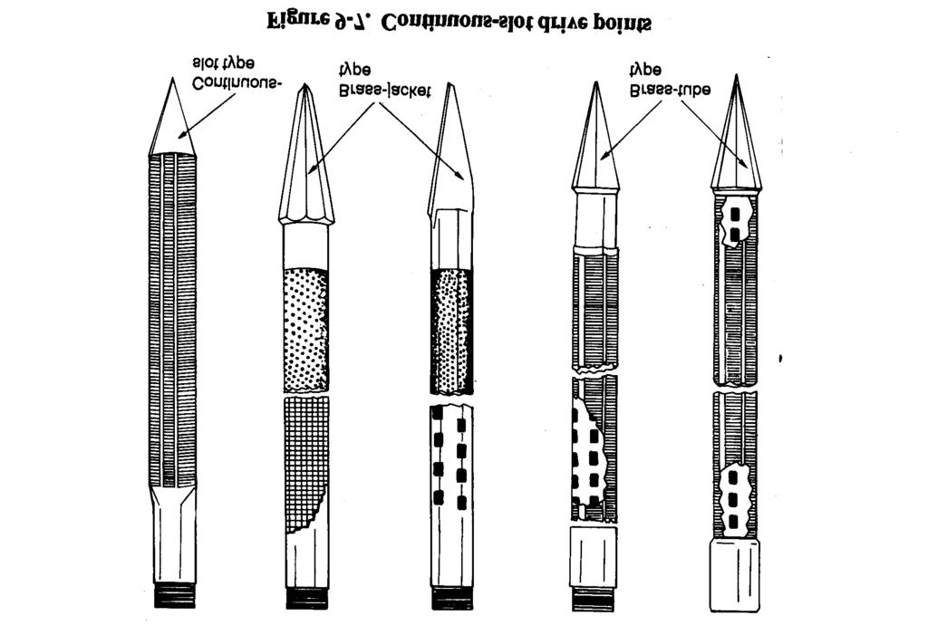

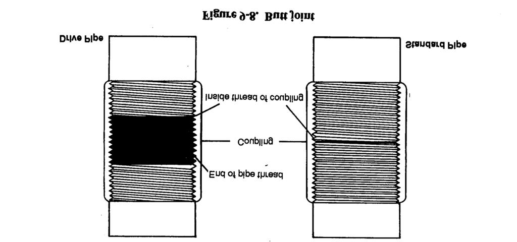
182 9-8
 used in driving casing or pipe are attached to the square of the drill stem.")
 Drive Heads.")


 to the lower end of the pipe to prevent the pipe from crumpling while")


183 (3) Drive Clamps. Drive clamps (Figure 9-9) used in driving casing or pipe are attached to the square of the drill stem. When driving the clamps, strike the drive head or coupling at the top of the casing. The stem acts as a guide through the head and furnishes the weight needed for driving. (4) Drive Heads. Drive heads (Figure 9-10) placed on the pipe protect the threads from the driving blows of the drive clamps. The drive heads are put on by unscrewing the bit, slipping the drive head over the drilling stem, and making up the joint again. If you use the screw drive head, make sure you unscrew the drive head from the pipe coupling before pulling the tools from the hole. (5) Drive Shoe. Always attach a drive shoe (Figure 9-11) to the lower end of the pipe to prevent the pipe from crumpling while being driven. A drive shoe is threaded to fit the pipe or casing. The inside diameter of the shoe below the shoulder is the same as the inside diameter of the pipe. A drive shoe is forged of high-carbon steel, without welds, and is hardened at the cutting edge to withstand hard driving. Screw the drive shoe tightly to butt the inside shoulder against the end of the pipe. (6) Elevator, Sand Line, and Pin Hook (Figure 9-12, page 9-10). Use casing elevators to handle pipe. The device clamps around the pipe directly under the coupling. You can use the sand line with the elevator for lifting one or two half lengths of pipe. For heavier strings of pipe, use the elevator with the swivel hook attached to the rope socket on the drilling line. 9-9
 Pipe Tongs (Figure 9-12).")

184 (7) Casing Ring and Slips (Figure 9-12). Use a casing ring to suspend the casing at the ground surface and for pulling pipe from the hole using jacks placed under each side of the casing ring. The rings are made of cast steel and are fitted with handles. All slips are cast steel, with sharp teeth properly hardened. (8) Pipe Tongs (Figure 9-12). Use chain tongs to tighten the 6- and 8-inch drive pipe. Should the pipe turn in the hole while adding a top length, hold the lower pipe with one tong and tighten the top length with another. If friction in the borehole is enough to hold the pipe while making up top lengths, use both tongs on the top length, opposite each other. Doing so puts an even strain on the pipe, eases the operation, and makes abetter joint. Pipe joints must be tight and kept tight while driving pipe; however, keep tong pressure low enough to avoid collapse of the pipe. (9) Pipe Clamps (Figure 9-13). You can construct wooden pipe clamps for 6- and 8-inch drive pipe. You can use the clamps to hold the pipe at any position in the hole during drilling operations. b. Procedures. (1) Borehole. Generally, driven wells are started in a hole bored with a hand auger. The diameter of the borehole should be larger than that of the well point, and the borehole should be as deep as the auger will work. In clay soils, boring with an auger is much faster than drilling. (2) Pipe Joints. Construct pipe joints carefully so that joints are airtight to prevent threads from breaking. If available, use special 9-10


185 drive-pipe couplings (Figure 9-14). Screw all joints tightly after cleaning and oiling the threads. Use joint compound to improve airtightness. When transporting and storing joints, you should protect them with caps or couplings. To ensure that joints remain tight, give the pipe a fraction of a turn with a wrench after each blow until the upper pipe joint sets permanently. Do not twist the pipe string while driving. (3) Pipe. You must keep the well pipe vertical. To check the angle, hold a plumb bob at arm s length from the well pipe and from two directions at right angles to each other. If the pipe is not vertical during the early part of the driving, straighten it by pushing on the pipe while the blows are delivered. If you cannot straighten the pipe, withdrew it and start in a new location. Use a maul or sledge to strike the drive capon the well pipe. Hit the drive cap squarely to avoid pipe damage. An alternative to manual driving is a driver that fits over the drive cap. If available, use a pneumatic tamper or sheet pile driver with an air compressor if the pipe is strong. A weak pipe will break at the couplings if you do not use a butt joint. (4) Casing. If you use unthreaded casing, butt-weld the casing lengths. Use an alignment collar for initial tack welding (Figure 9-15, page 9-12). The collar is used to align the pipe or casing to get a straight, tight joint. With the welded casing, you can drive a pipe string and possibly eliminate casing damage. Remove the collars when you complete tack welding. Another driving method involves a steel driving bar attached to a rope. The bar falls freely inside the pipe and strikes the base of the drive point (Figure 9-16, page 9-13). This method is safest because it does not weaken the pipe. The falling-weight method uses a drive monkey, which is a weight that slides over the pipe (Figure 9-17, page 9-14). A simple arrangement of this method is one in which the monkey slides on a bar supported by the well pipe. Use a drive cap with this arrangement. Another method is to slide the drive monkey over the well pipe to strike the drive clamp that is around the well pipe. You must use a tripod with either method. In soft formations, the descent rate may be 2 or 3 inches per blow. In sand or compact clay, using water in and around the pipe makes driving easier. Extremely compact clay is difficult to penetrate and requires many blows to penetrate a few inches. 9-11

186 Successful construction of driven wells depends on close observation and correct interpretation of certain work aspects while driving. Interpretation of details such as penetration made with each blow, drop and rebound of the maul or weight, sound of the blow, and resistance of the pipe to rotation helps the well driver to determine the character of the materials being penetrated. Table 9-2 (page 9-15) outlines a guide for the identification of the formation being penetrated. 9-12
187 c. Well Completion. (1) Straight-Pumping Method. You can develop a well with a pitcher-spout hand pump. The pump has a plunger and a check valve arranged so that the check valve trips when you raise the pump handle as high as possible. With this method, you can pump for an extended period before tripping the check valve. Tripping allows water to run back down the well pipe. By applying a heavy suction on the well and tripping the valve, you produce a surging action through the screen openings. The flow reversal, due to the surging, loosens the fine material plugging the screen openings and brings the fine sand and silt into the well point. If you pump continuously for severe 1minutes, these particles may be raised from the well. When the flow is clear, the well is ready for use. Check the pump to ensure that the valves and plunger are free of sand. (2) Alternative Completion Methods. If you cannot clear all the sediment from the well point by pumping, try any of the following methods: Method 1. Lower a series of connected lengths of 3/4-inch pipe into the well with the lower end resting on the sediment in the well point. Clamp the pipe in position and attach a hand pump to the upper end. Run water into the well pipe (not the 3/4-inch pipe) and operate the hand pumps. By steadily pumping, the sediment will be lifted through the 3/4-inch pipe. Continue to lower the 3/4-inch pipe to the sediment level until the well is cleared. 9-13

188 FM 5-484/NAVAC P-1065/AFMAN Method 2. Insert a string of 3/4-inch pipe into the well and fill the well with water. Repeatedly raise and lower the pipe sharply. Hold your thumb over the top of the 3/4-inch pipe during upward movements, and remove your thumb during downward movements. A jet of muddy water is expelled on each downward stroke. When the material loosens and is suspended, you can pump out the muddy water. Method 3. Pump water into a string of 3/4-inch pipe that is resting on the sediment to remove the fine material by a jetting action. This procedure requires a large supply of water and a motor-driven or hand-force pump. 9-14

189 9-4. Cable-Tool Method. a. General. Cable-tool drilling (churn drilling) produces a chopping action. The method and the tool are not expensive, and one person can operate the rig. Cable-tool drilling is a very slow method and is not as widely used as rotary drilling and percussion drilling are used. You can use a cable-tool drill to penetrate rocky soil or moderately hard sedimentary rock. The drill does not require large amounts of drilling fluid. Since the borehole is not full of fluid, you must drive casing as you dig the hole deeper to stabilize the wall. b. Equipment and Procedure. (1) Rig. The rig consists of a winch with a large wire-rope reel, a walking beam, and a mast. Make sure the wire rope is long enough to reach the anticipated depth. Advance the borehole using a suspended bit for chopping the soil or rock at the bottom of the hole. Thread the wire rope through the walking beam and over a sleeve at the top of the mast. As the walking beam goes down, the bit is lifted; as the walking beam comes up, the bit is dropped. As you dig the borehole, unreel the rope to keep the bit just at the bottom. If the borehole is dry, add water to a few feet off the bottom. As you lift and drop the drill bit, the material is chopped and mixed with the water. After an advance of a few feet, use a bailer to remove the mud. (2) Tools. A complete set of drilling tools includes the chopping bit and a set of heavy drill jars located above the bit. The stroke of the drill jars is such that when the walking beam is all the way down, the bit is above the bottom of the hole. When the walking beam goes up, the bit drops to the bottom of the hole; as the drill jars close, the bit is impacted. Using a drive barrel and long jars, take a sample from the bottom. The stroke of the long jars is longer than the stroke of the walking beam so that the drive barrel is not lifted off the bottom of the hole while driving with the impact of the jars. Cable-tool drilling involves many cycles. Each cycle involves reeling and unreeling wire rope and is a slower operation compared to a cycle on a rotary rig Augered Wells. You can construct bored wells using hand- or power-driven earth augers. Boring is practical where groundwater can be obtained at shallow depths and when small quantities are needed. Augered boreholes range from 2 to 32 inches in diameter and reach depths of 25 to 50 feet. Engineer troops can construct small-diameter bored wells using organizational equipment. 9-15
190 a. Equipment. (1) Hand Auger. These augers consist of a shaft or pipe with a wooden handle at the top and a bit with curved blades at the bottom. The standard engineer auger has fixed blades, but there are bits with blades adaptable to different diameters. Hand augers usually come with several shaft extensions and couplings. To add an extension, remove the handle, couple a section to the pipe, and replace the handle. Hand augers can penetrate clay, silt, and those sands in which an open borehole will stand without caving. (2) Power Auger. These augers are rotated, raised, and lowered by power-driven mechanisms. The turning force is transmitted to the auger through jointed square or polygonal stems. The power auger issued to engineer troops has a depth limit of about 10 feet. You can use this auger only in areas where the water table is close to the surface. b. Procedures. To start boring with an auger, force the auger blades into the soil while turning the tool. The auger will cut into the ground at a rate determined by the hardness of the soil. When the space between the blades is full of material, remove the auger and empty it. Repeat the operation until you reach the desired depth. When constructing bored wells, you may hit small rocks or boulders that will prevent further penetration. When this occurs, lift the auger from the hole; remove the cutting bit, and replace it with a spiral or ram s horn. Lower the tool into the hole and turn the auger clockwise. The spinal should twist around the rock so you can lift the rock to the surface. Remove the spiral, replace it with the regular bit, and continue boring. If you hit a large boulder that you cannot remove with a spiral, abandon the hole and start somewhere else. Wells less than 15 feet deep should not require equipment other than the auger. For deeper wells, use a light tripod with a pulley at the top or a raised platform so you can insert and remove a longer auger rod from the hole without damaging the rod and without unscrewing all pipe sections. c. Well Completion. If you reach loose sand and gravel, you may not be able to bore below the water table. To overcome this problem, lower a pipe or other casing to the bottom of the hole and continue to remove material while adding weight at the top of the casing to force the pipe down. If you cannot remove material from the hole, use a bailer or sand pump and make the hole deeper. Complete bored wells by installing well screens in the aquifer and developing the well as described in Chapter 7. You may also use drive points (paragraph 9-3a(l), page 9-6). If you find groundwater in jointed clay, complete bored wells by lining the hole with clay tile. Use bell- and spigot-type tile and set the tile in the hole with the bell ends down. Pour coarse sand around the tile. You cannot ensure a sanitary well using this completion method. Therefore, use this method when it is the only possible solution. 9-16
191 Chapter 10 Arctic Well Construction Considerations. a. Arctic Water Supply. Supplying water for operations or bases in the Arctic and adjacent cold regions requires careful planning due to the harsh climate and ground conditions. Potable water is widespread at the surface in some cold regions but is uncommon in more arid cold regions. Locally, surface water can be melted from ice or pumped from unfrozen lakes or glacial-melt pools. Many surface sources are only dependable during the summer months, leaving potential problems in supplying water throughout the year. More dependable, year-round supplies of groundwater may be developed through wells in relatively shallow, unfrozen strata (Figure 10-1) and from wells that fully penetrate the permafrost. WARNING Do not touch cold metal with your bare hands. 10-1
192 Permanently frozen rock and soil are widespread in the Arctic north of 50 o N latitude. This condition restricts groundwater development because some of the groundwater is permanently frozen and not available. The frozen zones, which vary in thickness from a few feet to 2,000 feet, are impermeable aquicludes and inhibit the upward movement of unfrozen groundwater. The difficulty of obtaining water increases northward as the permafrost thickens and becomes colder and more continuous. b. Discontinuous Permafrost. In this zone, permafrost will be thin and may be absent on the south slopes of hills, in valley bottoms containing permeable alluvial material (sand and grovel), and under surfaces that have been cleared of vegetation (airport runways, farmlands, forest-fire scars, and logging tracts). Obtain information from local sources regarding springs (icings), existing wells, unfrozen zones, and caves used for storage. Consider obtaining water from surface sources before drilling and developing wells in the permafrost zone. The existence of a good, year-round water source at the surface in the discontinuous zone will indicate that the ground is not frozen beneath the well. Year-round springs, large streams, and lakes can serve as water sources. Even if the water is unpotable, these sources indicate windows in the permafrost where dug, driven, jetted, or drilled wells may be located. Vegetation could indicate the presence and thickness of permafrost. Tree roots rarely exceed a depth of 3 feet. Therefore, the presence of large trees may indicate that only the top of the permafrost during the thawing season is deeper than usual. Large trees along a river could suggest that either the top of the permafrost is depressed to afford a limited supply of water or that permafrost may be absent. The presence of pine or aspen may indicate a similar depression of the permafrost table or possibly the complete absence of permafrost. The presence of willow shrubs (not trees), peat and moss, or stunted tamarack and birches may indicate a thin zone of summer thawing (active zone) and the presence of cold, thick permafrost near the surface. These indicators are more frequent in a thick, continuous permafrost zone. c. Thick, Continuous Permafrost. Generally, you will have to use surface sources when underlain by thick, continuous permafrost. Available groundwater will require drilling deep (several hundred feet) wells through the permafrost. Such a task may be beyond the scope of a military operation Well Drilling. a. Drilling Equipment. You will use the same drilling equipment as for normal well drilling and additional accessories required because of adverse weather conditions. You will need portable gasoline or diesel heaters for personnel and equipment at the construction site. You will also need electrical or oil immersion heaters for storage and settling reservoirs. You should have tents or sheds as protection for personnel from cold winds or storms. b. Rotary Drilling. In permafrost regions, use the rotary-drilling method for deep drilling and large diameter holes and for shallow drilling and small holes. The procedure for rotary drilling in frigid climates is the same as in temperate climates except for temperature requirements of the drilling fluid. In adverse weather conditions (extremely low temperatures and snowstorms), construct shelters to protect the rigs and to maintain comfortable working temperatures. At temperatures below -20 F, generally no drilling is done. The mud used in rotary drilling should beat near-freezing temperatures when entering the drill stem to prevent thawing and caving 10-2
193 of the hole. When necessary, apply enough heat to the mud to prevent the hole from freezing. Make sure the rig operates continuously to prevent the mud pump and accessories, bits, and casing from freezing during operations. If you must stop operations at night, remove the tools, let ice form, and drill out the ice in the morning. In a finished well, you can use the rotary rig to circulate the water to prevent freezing until you can install a pump. c. Jet-Drive Drilling. This is another method of constructing small wells in cold climates. You can also use this method in warm or discontinuous permafrost. The wells are usually 2 inches in diameter and are drilled to a depth of 200 feet. Use the procedures and equipment described in Chapter 9 to construct the wells. The equipment is simple and light and consists of small derrick and a small engine with a cathead. You push the pipe into the ground and advance it manually dropping a small weight fastened to a line running over a sheave on the derrick to the cathead. The jet point is made from a reducer, which is ground into a bullet shape and attached to the end of the 2-inch pipe. Drill several l/4-inch holes above the jet point a distance of 1 to 2 feet. A thaw-line pipe projects a maximum of 2 feet through the head of the drive point. Pump a water jet through the thaw-line pipe during drilling operations. Suspend the pipe on a simple chain hoist and slowly move the pipe up and down. The thaw-line pipe will penetrate the sediments ahead of the jet point. When the thaw-line pipe is about 2 feet ahead of the jet point, retract the pipe. The casing is driven as far as it will go; repeat the process. Use water no warmer than 40 o F in this process. Jet-drive drilling proceeds about three times as fast in permafrost as in thawed ground. See Figure 9-2 (page 9-2) for a rig you can use in Arctic well drilling. Figure 10-2 (page 10-4) shows a jet-drive point you should use with the rig. For depths of 100 feet or less, one man operating a rig can jet drive about 28 feet per day in frozen ground. If the ground is thawing, the footage per day is reduced. The well can yield 40 gallons of water per minute from a 2-inch well equipped with a suction pump with less than 20 feet drawdown. At a depth of more than 100 feet, jet-drive drilling becomes rather slow and difficult. Therefore, try to limit jet-drive drilling to the southern portions of the permafrost zone. d. Drilling Fluids. The fluid used in drilling through permafrost must remain in a liquid state during drilling operations and must not contaminate possible water sources. You can eliminate possible contamination through pumping. When using mud, try to keep the mud from freezing by adding chemical agents such as aquagel, gel-flake, barite, fibratex, smentex, micatex, and impermex. Be careful during periods of excessive permafrost thawing. The hole could slough during drilling. Do not heat the drilling fluid. An increase in the viscosity of the drilling mud will result in a decrease in mud flow, eventually causing freezing or sticking of the bit. Brine, as a drilling fluid, is not ideal in permafrost areas because it promotes contamination and excessive thawing. It could corrode the drill string, rig, and pump and cause a skin rash on personnel. Use brine sparingly, when required. In normal water-well drilling, you develop the well by pumping after drilling, which clears the well of brine. A suitable brine solution would be 35 pounds of rock salt mixed with 53 gallons of water. In the Arctic, 100 pounds of rock salt is ample for drilling a 15- to 20-foot hole. (Figure 10-3, page 10-4) shows the specific gravity of drilling fluids when using salt additives in mud-drilling operations.) You must clean drilling equipment after using brine. 10-3


194 CAUTION Adding salts to drilling fluids will reduce the viscosity, e. Air Rotary Drilling. This is the preferred drilling method for intermediate- or large-depth wells if you have the equipment. You do not have to take the same precautions as with rotary drilling. f. Well Installation and Completion. You can use some of the same installation and development methods in cold climates as you did in warm climates, with some precautions. Try to minimize prolonged contact of surface water with any permafrost. Doing so will avoid freezing in the hole or thawing and sloughing the previously frozen wall and the need to redrill. You can use the single-string method to install screen and casing together for wells in rock-like permafrost because disturbance is minimal. The potential for water freezing after the well starts routine production should be reviewed. You could insulate the well by centering a regular well casing in an oversized drill hole and by packing the annulus with dry sand through the permafrost interval. You could then fit the well for continuous rather than intermittent pumping. 10-4
195 Chapter 11 Auxiliary Activities Exploratory Drilling. a. Geological Exploration. Use the same drilling methods for subsurface geological exploration as for standard well drilling. However, you will need special accessory equipment. See Table 11-1 for drilling methods and material samples. Auxiliary equipment for exploration drilling may include solid and hollow-stem augers, sampling tubes, core barrels and bits, crackerjack bits, wash casing, and bailers. All the equipment is effective for sampling but varies for exploratory drilling, depending on conditions. In shallow depths, use augers. However, auger samples are disturbed and are not suitable for strength determinations. The samples can provide data such as soil type, water content, layer thickness, and changes in formation. Use a rotary or a down-hole drill for depths beyond an auger s range. Use these methods to obtain data for placing bridge abutments and structures and for determining the location, depths, and bearing stratum for other structures such as foundations, piles, dams, and underground facilities. You may have to drill boreholes to reach the materials that have good bearing capacities, to establish soil and bedrock profiles, and to reveal flaws in rock formations. You may perform the same well-drilling procedures for several tasks. When drilling, be swam of water occurrences and where drilling fluid loses circulation. These signs could indicate flaws in the rock. In shallow depths, use the jetting method to obtain the same information. b. Logging Techniques. In exploratory drilling on military installations or major facilities, a geologist will often be assigned to conduct the logging at the rig. The geologist provides directions on objectives and assistance on methods of sampling. Inexpedient field operations, the driller may have to serve as a technician and make all observations and logs. 11-1
196 The driller should log each borehole regarding the depth reached and material taken. For field logging of unconsolidated materials, use the Unified Soil Classification System in FM for consistency and compatibility of terms. The driller may have to rely on initial visual examination of cuttings to describe the formation being penetrated. c. Drilling Action. The driller should recognize changes in earth formations by the actions and sounds of all well-drilling equipment. For example, a change in pump circulation could indicate an aquifer. The driller should include such information in the log Sampling Soil and Rock. A valuable source of geologic and hydrologic information is cuttings from the penetrated rock. Handle these cuttings carefully. Collect samples from various depths to obtain the complete lithologic character of the formations penetrated. Use the coring method to take samples. With this method, you extract a solid piece of the formation. However, you can achieve the same results by carefully collecting loose cuttings. a. Rotary Cuttings. (1) Method. Examine the cuttings deposited in the return ditch or around the collar of the hole to determine the material the bit penetrates. If you are digging a deep well, take a sample every 5 feet. If you are digging a shallow well, take samples at shorter intervals. Hoist the bit about 1 foot off the bottom, and rotate slowly while the mud circulates at full volume. Continue until the hole washes free of drill cuttings. Resume drilling for another 5 feet, raise the drill pipe slightly, and let the mud circulate until it is clean of drill cuttings. If you use this procedure, the mud is screened carefully as it flows in the return ditch. You can obtain samples to identify the different beds. (2) Contamination. Soft formations have a tendency to cave in and add extra materials to the drilling fluid. When the drilling mud circulates, this material comes to the surface and contaminates the sample. Material from the upper formation can also contaminate the sample when drilling mud is not heavy enough to cushion the impact of the drill pipe against the walls of the well. You can eliminate much of the contamination if you make the mud pits large enough to ensure the settling of all the particles of the cuttings before the mud circulates into the hole. If you want an uncontaminated sample, stop drilling and continue circulation until all cuttings are washed to the surface. Clean the ditch, proceed with drilling for a few inches, and catchall the cuttings that wash out. This sample represents the material drilled, provided the fine sand and silt are not carried into the settling pit in the drilling mud. b. Depth Determination. Determine the depth of a sample by measuring the lag time, which is the time it takes for material to reach the surface. Lag time depends on-- Size of the hole. Condition of the hole. Type of formation penetrated. Type and viscosity of the mud. Actual depth of the hole. You can measure lag time by placing material such as cut straw into the intake drilling mud pipe and recording the time it takes for the material to math the surface. Or, you can-- Stop the drill. 11-2
197 Circulate the mud until it is free of cuttings. Drill down a few inches. Stop drilling and measure the time required for the cuttings to reach the surface. The last procedure has the advantage of furnishing an accurate sample of the formation at the depth of the bit. Use the procedure when you want very accurate formation samples. c. Undisturbed Soil Samples. To collect these samples, advance the hole using a rotary or auger rig to a position just above the sampling interval. Clean the hole in the dry (when using an auger) or by flushing (when using a rotary rig). Recover the soil sample using either of the following methods: (1) Push-Tube Method. With this method, you can use thin-wall, fixed-piston samplers in very soft to stiff clays, silts, and sands that do not contain appreciable amounts of gravel. Use 5-inchdiameter sample tubes for all clays and silts that you can remove from the tube and keep in an undisturbed state. Some very soft clays and silts will not support their own weight, so you will not be able to remove them in an undisturbed state. You can take samples of these soil soils with either 3- or 5-inch-diameter sampler tubes. Seal the sample in the tube with expanding packers. Generally, a 3-inch-diameter sample of clean sand is sufficient. Before sampling, chuck the drill rods in the drill rig with the drive mechanism raised to its maximum height. Doing so prevents the weight of the drill rods and sampler from bearing on and possibly disturbing the sampled material. Rotate the piston-rod extensions to the right until the piston-rod clamp or locking mechanism in the sampler assembly is released. Clamp the piston-red extensions to the drill-rig mast. Place a mark on the piston-rod extension where it emerges from the drill rod. Marking the rod will help you determine the exact length of drive. The sampler is ready to push. The capability of the drilling rig to perform a continuous, smooth push limits the length of the drive. In noncohesive soils below the water table, the vacuum caused by the piston can cause piping of the sample if the drive length is excessive. Samplers 24 to 30 inches in length are reasonable. The most satisfactory method of pushing an undisturbed sampler is with the drive mechanism (preferably hydraulic) on the drill rig. The rig must be firmly anchored to prevent the reaction of the drive from raising the rig and the sampler piston. Screw-type earth anchors are sometimes used. You must advance the sampler in one continuous push at a uniform rate. Do not rotate the sampler during the drive. If the drive is interrupted, do not restart it. Adhesion and friction develop between the sample and the tubing wall during an interruption. Restarting the drive will result in increased penetration resistance and disturbance of the sample. Withdrew the sampler, advance and clean out the hole, and make a new sample drive. (2) Core Method. If the sample material contains gravel or is too hard for a thin-wall sampler, use a double-tube core barrel or a Denisen sampler. These barrels are commonly used in obtaining samples of very stiff, brittle, dense, or partially cemented soils and of soft, broken, fissured, or friable rocks. Use the following procedures for this method: Step 1. Lower the core barrel to within a few feet of the bottom of the hole. Step 2. Circulate the drilling fluid to remove any excess cuttings that may have settled to the bottom. 11-3


198 Step 3. Lower the core barrel to the bottom. Rotate and force the barrel downward at a uniform rate. If the soil erodes easily and the inner-barrel shoe will penetrate the soil under the pressure exerted on the core barrel, the inner-band shoe should extend below the cutting teeth of the outer bard. If this does not occur, use a shorter shoe that has a cutting edge even with or slightly above the cutting teeth of the bit. Adjust the rotation speed and the advance rate to ensure that the bit penetrates continuously. If the bit advances too rapidly, it will become plugged and grind away the core. If the bit advances too slowly or intermittently, the core will be exposed to excessive erosion and torsional stresses. Use a rotational speed of 50 to 150 RPM for most soil coring. You must control the drilling-fluid pump pressure and flow when removing cuttings. Too much drilling-fluid pressure and flow will erode the core. Too little drilling-fluid pressure and flow will allow the cuttings to enter the core barrel, along with the core, and plug the bit. Try to use experienced personnel to regulate the bit pressure, speed of rotation, and drilling-fluid pressure. However, you might have to experiment due to the variety of core barrels and drilling fluids and variations in soils. d. Rock Core Samples. You may recover undisturbed core samples from hard rock formations with the rotary-drilling rig. As with other sampling methods, core drilling requires special auxiliary equipment and procedures. The diamond core bit and double-tube core bard are basic equipment (Figure 11-1 ). The assembly consists of an outer rotating tube or barrel attached to a core barrel head at the top end and the diamond drilling bit at the bottom. An inner tube and core lifter receive and hold the sample stationary within the rotating assembly during drilling. Drilling fluid circulated downward between the inner and outer tubes and the sample remain protected. To take samples: Lower the core barrel and bit into the borehole through the hollow drill rod. Start circulating the wash water before the core barrel reaches the bottom of the hole to prevent cuttings or sludge from entering the core barrel at the start of coring. The optimum rotation speed of drilling varies with the type of bit used, the diameter of the core barrel, and the kind of material to be cored. Excessive rotation speed will result in chattering and rapid wear of the bit and the core will break. Low speed results in less wear and tear on the bit and better cores but lower rates of progress. In medium to hard rock, use 300 to 1,500 RPM for diamond bits and 100 to 500 RPM for metal carbide bits. The advance rate of the coring bit depends on the material s firmness, the downward pressure applied on the bit, and the rotation speed. The driller must carefully adjust the pressure. Too much pressure causes the bit to plug and to shear the core from its base. Bit pressure is controlled by a 11-4
199 hydraulic or screw feed on the drilling machine. The weight of the drill-rod column seldom exceeds that of the optimum bit pressure for coring medium and hard rock. You may have to apply additional downward pressure Installing Monitoring Wells. These are small water wells used for measuring water level, estimating well yield, and taking samples for quality analysis. These wells are drilled next to permanent wells at specified intervals. a. Safety. Before installing a well, the safety of the drill crew and impact of drilling on the environment must be considered, especially in areas containing hazardous wastes. Potentially hazardous categories are chemical wastes and residues, flammable wastes, explosives and explosives wastes, biological materials, toxins, radioactive materials, and harmful secondary vapors. Drilling crews may need protective clothing and respirators while working in such areas. b. Requirements. Well-drilling equipment is suited for installing monitoring wells. Use the hollow-stem auger for boring clean holes while simultaneously supporting the borehole wall during installation. Some piezometers use stock-porous well points. However, the installation methods are quite similar. Be careful when taking samples for water pollution testing so that contamination is not caused by the installation process. c. Installation. (1) Materials and Construction. Casings and screens can be mild steel, stainless steel, PVC, or chemical-resistant plastics such as teflon. Casing ends are threaded for tight couplings. Monitoring wells have a casing, screen, filter pack, and grouted intervals similar to water wells except smaller. A 2-inch casing is the most common. Filter-pack sand should be just coarse enough to stay outside the slotted semen. You can use bentonite pellets above the filter-pack and screened interval to seal the annulus and prevent water from leaking downward into the sampled stratum and contaminating well intake. Make sure that all materials used in the well are sterilized, including the drill rig. (2) Procedure. To install a monitoring well-- Drill the hole about 1 foot below the position of the screen bottom. Place 1 foot of filter-pack sand in the bottom. Insert casing and semen (single-string) and center in the hole. Slowly add filter-pack sand while tapping and twisting the string to settle sand firmly. Continue falter-pack addition upward to at least 1 foot above the screen. Add bentonite pellets to the annulus above the filter pack for at least 2 feet. Seal the remainder of the annulus to the ground surface and grout in a protective collar Supporting Construction and Demolition. Support for drilling operations for a construction or demolition unit is an expedient mission. The supported unit determines drilling requirements. A support mission is used as an alternative to mobilizing and fielding a separate drilling operation. For construction support, you can use a water-well rig with supplemental equipment for rock excavation. You will need bits designed specifically for drilling rock rapidly without sampling. Rock bits include button bits used in down-hole drilling and tricone and other hard roller bits for 11-5
200 rotary rigs. Rock-drilling applications might include foundation preparation, road cuts, and weapons pits. For demolition support, a demolition specialist will provide specifications and guidance for preparing area for emplacing demolitions or munitions. For information regarding safety when using explosives and demolitions, see FM You should use the rotary rig and special bits for expedient drilling and for placing demolitions. In soil, auger bits are ideal for shallow depths. The auger has large-diameter capabilities that may be necessary for placing large charges. The demolition specialist will describe techniques for handling equipment and accessories during emplacement. You can provide information about cavities and joints in formations that could adversely affect demolition and about the position of the water table, which could be important in dry versus wet conditions. WARNING Handle and use explosives and demolitions properly. 11-6
201 Appendix A Water Detection Response Team A-1. Concept. In a combat environment, well-drilling production supplies the water requirement. Groundwater sources must be located quickly before committing well-drilling teams. Terrain teams assigned to theater-, corps-, and division-level units make recommendations on well-drilling sites. If the geographic information the military provides the terrain teams is insufficient, terrain or well-drilling teams determine well-drilling sites by best-guess methods. Also, terrain teams are not trained or equipped in groundwater detection techniques. Because of these limitations, the WDRT concept was developed to increase the overall effectiveness of well-drilling operations. Professionals and state-of-the-an equipment help accomplish the roundwater detection mission. The subsurface WDRT consists of US government personnel who support military well-drilling operations by performing groundwater detection. Civilian contractors may also be used. The WDRT provides technical skills in remote sensing, geophysics, geology, and hydrology. The WDRT currently consists of on-call federal civilian employees who respond within 48 hours to a request to assess the subsurface hydrological situation any place in the world. Plans for on-call military personnel are also being developed. The team recommends drilling sites that have the best potential for producing water to meet tactical requirements. Specialists are drawn primarily from the Corps of Engineers. Other government organizations, such as the United States Geological Survey (USGS), participate when needed. Corps of Engineers organizations include the-- US Army Corps of Engineers Topographic Engineering Center (TEC). US Army Corps of Engineers Waterways Experiment Station (WES). Transatlantic Division (TAD). Mobile District, Savannah District, and other Corps Districts. A-2. Organization. The WDRT consists of four functional elements: data base, remote sensing, supporting specialists, and geophysical. The TEC-Terrain Analysis Center (TAC) manages WDRT and provides leadership for the data base and remote sensing elements. The geotechnical laboratory at WES provides leadership for the supporting specialists and geophysical elements. The supporting specialists consist of civilian personnel who are geographers, botanists, hydrogeologists, foresters, well drillers, and area experts. A working team is selected and mobilized within 48 hours of a validated tasking. The team may convene at the TEC-TAC to begin work by reevaluating data and imagery for the area of interest. The knowledge of the team and available information may be sufficient to identify areas with high potential for developing water sources. Additional information, such as data from remote-sensing systems and hydrogeologic data, may be acquired from other sources. A-3. Deployment. If data is still insufficient, WDRT will select and specify areas for conducting field reconnaissance and geophysical surveys. Depending on mission requirements, a team may deploy before or with the well-drilling team to assist with site selection and well design. Team members contact host-nation groundwater experts, evaluate any existing local groundwater sources, and conduct detailed hydrogeologic reconnaissance of areas previously identified as high potential water sources. The geophysical element of the team has the capability to conduct electrical resistivity, seismic refraction, and other geophysical surveys to assist in this field work. Once the well drillers begin drilling, the supporting specialists can assist with well design, drilling expertise, A-1
202 and on-site geologic support. On-site geologists assist in logging and interpreting cuttings from the well and with down-hole geophysical logging, when necessary. Down-hole logging is crucial in identifying the highest water-producing zones during rotary mud drilling. Subsurface geophysical surveys take time. If the geophysical element of WDRT deploys, enough lead time must be allotted for the team to conduct surveys. Planners overseeing contingency plans should include WDRT work in their plans. Much of the work can be done before drilling by specifying areas of interest so that data and imagery can be collected, analyzed, and placed on file. Planners should inform WDRT of the following: Size of unit to be supported. Type of unit. Quantity and quality of acceptable water. Duration of requirement. The WDRT usually deploys on military cargo aircraft with detection equipment packages of up to 1,000 pounds of geophysical equipment. Once deployed, WDRT maintains this equipment, shipping it back to the owning agency for contract repair, if necessary. For seismic work, WDRT may use small explosives (some of which may be standard military block explosives). The explosives are binary in nature and are mixed in the hole before detonation. The area commander supports the WDRT with logistical and administrative support to include transportation, shelter, medical support, communications, food, water, and other classes of supply. A-4. Operational Concept and WRDB. Army commanders or staff officers who require the potential well-site locations should contact the supporting Army Engineer Terrain Team. This team evaluates available data, especially the data supplied from the WRDB. The TEC-TAC is responsible for producing and maintaining the WRDB. The WRDB provides information on quantity, quality, and availability of water resources worldwide on an areal or point basis. This information helps commanders make water-support logistics decisions and supports the Defense Mapping Agency s (DMA) terrain-analysis program. The data base includes hard-copy thematic overlays (1:250,000 scale base maps) that show the location, quantity, quality, and accessibility of existing water resources, surface water supplies, and potential groundwater sources in selected arid regions in Southwest Asia. The terrain team evaluates the database and responds directly to the requester, if sufficient data is available. If no data is available or if more information is needed, a WDRT could be formed. The terrain team sends a request for assistance in locating groundwater supplies through Army Command channels to the US Army TEC-TAC. The WDRT manager at TEC-TAC designs a team from the on-call roster. The chain of command for other components from unified or specified commands to request data is the Terrain Team of the Army component command or through command channels, Joint Chiefs of Staff (JCS), and DA. Locating and evaluating water supplies in an area would be conducted in an integrated systems manner, beginning with data-base querying and followed by examining imagery and maps. The support command would decided which areas needed additional surveys. A WDRT may be deployed to conduct field geologic reconnaissance and geophysical surveys. Geologic reconnaissance will often be conducted without actual geophysical surveying. All available information, including field reconnaissance, will be used when categorizing potential well-drilling sites for the supported unit. A-2
203 FM 5-484/NAVFAC P-1065/AFMAN A-5. Water Resources Overlays. The product of WRDB is a set of three transparent overlays keyed to standard 1:250,000 scale Department of Defense (DOD), Joint Operations Graphics (JOG) topographic maps. The overlays provide the most current information for existing water-supply facilities, surface-water resources, and groundwater resources. The three overlays should always be used together to determine the water-supply potential of the area. a. Existing-Water-Supply Overlay. An existing-water-supply overlay displays all known man-made or improved facilities except for surface water bodies larger than 0.25 square kilometeters, canals, wells, springs, and qanats. This overlay also shows the location, capacity, and quality of water in existing production, distribution, and storage facilities. These facilities include desalination, waste treatment and other purification plants, storage facilities, pumping facilities, pipelines, and miscellaneous supply facilities, such as ice-making and water-bottling plants. b. Surface-Water Overlay. A surface-water overlay supplements the map and depicts surface-water resources, such as perennial water bodies (lakes and reservoirs), streams and rivers, dams, canals, and surface-water access areas. The overlay will contain information, if available, on water volume, flow rates, quality, and seasonality of water. c. Groundwater Overlay. A groundwater overlay concentrates on groundwater potential. If existing facilities cannot meet field water-supply needs, planners should use the surface and groundwater overlays to determine where and when to drill water wells. If planners decided to develop a water well, they should look at the information on the groundwater resources to help site the well. The drilling unit should also have this information to execute a successful completion. Whenever possible, the WDRT should assist by recommending specific drilling sites. Military terrain analysts and well-drilling planners use the groundwater overlay to identify areas of groundwater resources. Using the overlays greatly increases the potential of siting and developing successful water wells. From the overlay, areas of greatest groundwater potential can be determined, along with the expected characteristics of the aquifer and overburden (material to be drilled through to reach the aquifer). d. Overlay Symbols. Potential water sources, where a point feature is located, are depicted by symbols and include water wells, well fields, springs, and qanats. Symbols that appear on the overlay with an adjacent number are keyed to a table with additional information. The areas of potential groundwater development are designated as Good(G), Marginal(M), Poor(P), or Unsuited (U). Areas of similar potential groundwater development may be further subdivided and designated with number suffixes such as M 1 and M2. Each potential area is keyed to a characteristics table printed in the margin of the overlay. These characteristics describe the potential yield of a well, depth to aquifer, aquifer thickness, water quality, overburden materials, and aquifer materials. Each area designated will have a set of groundwater characteristics associated with them. The characteristics are given a numeric code that places them in one of four classes. The rock types listed under overburden materials and aquifer materials should be considered only representative of the properties and not exact geologic descriptions. The driller can expect the hardness of the overburden to increase as the class number increases from 1 to 4. Aquifer-material classes indicate the more favorable aquifer in terms of yield and ease of drilling; the greater the number, the less favorable the aquifer. Sand and grovel aquifers consist of unconsolidated materials with a large percentage of unfilled pore space. These aquifers are usually the best regarding yield A-3
204 and ease of drilling. Igneous aquifers are usually the largest and have the least amount of porosity and hydraulic conductivity and may be tough to drill through. Sandstone and limestone aquifers have properties between sand and grovel and igneous aquifers. If a limestone aquifer is cavernous and is expected to yield large quantities of water, the analyst preparing the overlay could rate the aquifer as a 2. This rating indicates that the aquifer material is better than the 3 rating normally assigned to limestone. A-6. Potential Drilling Areas. The following are reasons for areas to be eliminated or marked as unsuitable well-drilling sites: If an aquifer is more than 1,500 feet deep, because military well-drilling machines cannot reach that depth. If no significant groundwater exists. If successful well completion is unlikely because of overburden materials, limited aquifer extent, or groundwater barriers restricting water flow. Besides map legends, Supplemental lnformation should include detailed statements on seasonal groundwater fluctuations, bacterial contamination, geology, and other pertinent information. Feature, with numbered symbols on the overlay, are entered into a Potential Water-Data Table. The numbered features include information on the following: Well location. Well yield. Water quality. Well depth. Overburden and aquifer materials. Well use. Water-chemistry data. Water fluctuations. Feature names. Numbered features on the overlay may also be keyed into a WRDB Analyst Report Form-Record Characteristics form that allows for the recording of particular technical information on the feature. Information such as construction and design of existing wells, pumping test results, and other data that will aid in the design of new wells or assist in the maintenance of existing wells should be included. Most overlays are classified SECRET or CONFIDENTIAL. To order overlays, write to US Army Topographic Engineer Center, ATTN: CETEC-TC-H, Fort Belvoir, Virginia , or call DSN or commercial (703) A-4
 Seabees, as part of their primary mission,")

 and well-drilling")

")
205 Appendix B Navy Well Drilling B-1. General. The Naval Construction Force (NCF) Seabees, as part of their primary mission, are tasked to provide water-well-drilling support for the Marine Corps. Doctrine for this support is in OH13-4/NWP Each naval mobile construction battalion (NMCB) table of allowances (TOA) includes four water-well-drilling technicians (NEC 5707) and well-drilling equipment and materials to develop water wells from deep subsurface aquifers. To accomplish the well-drilling missions, well-drilling teams deploy from an NMCB by land, air, or sea. B-2. Equipment. The NMCB TOA includes one International Standards Organization (ISO) air-transportable water drill (ITWD) (Figure B-1), one 750-psi/300-cfm air compressor, and two 1,500-foot well-completion kits. B-1


 engineer units. The machine is compatible with the Service Logistical Vehicle Systems (LVS).")

206 a. The ITWD. This machine replaces the LP- 12 1,500-foot well-drilling machine and the semitrailer-mounted Portadrills, models 501 and 521. The ITWD is an all-wheel-drive, self-propelled rig that can be shipped in a standard 8- by 8- by 20-foot IS0 shipping container. The ITWD can also be shipped on a C-130 or larger aircraft without disassembly. The machine is an all-hydraulic, top-head drive unit with a telescoping mast capable of employing standard 20-foot drill steel. The ITWD has a top speed of 10 miles per hour (mph) and is not designed for over-the-road mobility. It is lightweight, highly mobile, and suitable for rapid deployment with Fleet Marine Force (FMF) engineer units. The machine is compatible with the Service Logistical Vehicle Systems (LVS). See Table B-1 for specifications on the ITWD. The ITWD is capable of mud and air rotary drilling, rotary percussion, or down-hole hammer drilling, using an auxiliary air compressor. A mud pump, water-injection pump, in-line oiler, four comer-mounted leveling jacks, fore and aft pintle hooks, utility hoist, driller s station, and driver s station are mounted on the ITWD. The ITWD is deployed with a kit that includes lightweight drill steel, drill collars, tricone bits, down-hole air hammer, and miscellaneous subs and adaptors for drilling to a depth of 1,500 feet. Because of the various drilling capabilities, the ITWD can drill in any geological formation. If drilling requires the air compressor, it is brought to the site with the drill rig or delivered by a support vehicle. For mud-drilling operations, teams need a water truck and the equipment to dig the mud pits. b. Air Compressor. One wheel-mounted, diesel-engine-driven, 750-cfm, 300-psig air compressor is included in each NMCB TOA for performing down-hole hammer drilling techniques. The ITWD is capable of towing this air compressor. The ITWD does not have on on-board air compressor. c. Well-Completion Kit. Each NMCB TOA includes two 1,500-foot well-completion kits. Materials in these kits are considered consumable project materials. The kits are used to develop and complete a well. The supported unit is responsible for replacing the materials in the kits. B-2
.")
207 Appendix C Air Force Well Drilling C-1. General. Air Force well-drilling teams are organized and assigned according to Air Force Instruction (AFI) This publication outlines the organizational concepts and capabilities of the Rapid Engineer Deployable, Heavy Operational Repair Squadron (RED HORSE). This squadron provides the Air Force with a highly mobile, self-sufficient, rapidly deployable, civil-engineering, heavy construction and repair capability. The Air Force headquarters control RED HORSE. Welldrilling units are assigned as a special-skills team to an operational RED HORSE unit. The unit provides the logistical support necessary to complete the well-drilling mission and the administrative support well-drilling teams require (Table C-l). These units are classified for deployment using the following categories: a. RH-1. This is an air-transportable RED HORSE echelon composed of 16 people. An RH-1 team is ready for deployment 12 hours after notification. The squadron can perform advanced airfield surveys and site layout and can prepare for the orderly establishment and future development of a base of operations during contingencies. b. RH-2. This is an air-transportable RED HORSE echelon composed of 93 people. An RH-2 team is ready for deployment 48 hours after notification. The squadron can erect base shelters and perform limited earthwork and light base development during the initial phase of contingencies. Light base development includes installing aircraft arresting systems, expedient airfield matting, and essential utility systems. c. RH-3. This is a RED HORSE echelon composed of 295 people. An RH-3 team is ready for deployment six days after notification. Continental United States (CONUS)-based RH-3 personnel usually deploy by air to the TO where they can be joined with pre-positioned RH-3 equipment. CONUS-based RH-3 equipment usually moves overland to the TO. However, most RH-3 equipment is air-transportable on a C-5. With equipment, an RH-3 team is capable of performing heavy repair, runway repair, facility hardening, and airfield expansion, to include erecting relocatable facilities to support contingency operations. C-2. Organization and Scope. Well-drilling teams are required to develop and provide adequate water resources for deployed forces. a. Capabilities. The well drilling teams should be able to do the following: C-l

208 Disassemble, transport, and reassemble the drilling rig. Set up the well drilling rig and support equipment. Drill a 1,500-foot, 6-inch diameter well. Drill with mud, air, and foam circulation. Drill with down-the-hole hammer. Drill in sand, soil, clay, rock, or other geological formations. Perform operator s service checks and maintenance. Develop the well for connecting and interfacing with storage facilities and water-distribution systems. b. Requirements. The hazards and risks associated with water-well drilling require the highest standards of training, proficiency, and safety. The following publications have specific responsibilities that apply to water-well operations: AFI AFI AFI TA 429. Operations, maintenance, and repair manual for the assigned well-drilling rig. Repair parts manual. c. Team Composition. A water-well-drilling team will be composed of a minimum of 12 trained personnel. The team must provide a four-man, 8-hour shift, 24-hour drilling operation. Teams should be primarily 3E2X1 (construction equipment) personnel in grades E3 through E8. However, other Air Force Specialty Codes (AFSCs) should be considered, such as 3E4X1 (utilities system specialist). The team must consist of 8 RH-2 and 4 RH-3 personnel. The officer in charge or noncommissioned officer in charge of the RH-2 or RH-3 team has the responsibility for well drilling. The 12-man team should be broken down to 3 four-man teams. Special positions and duties are as follows: Tool pusher (supervisor). Outlines the drilling program and sees that it is carried out. Driller. Operates the drilling rig. Derrick hand. Works in the mast, racks the steel, and so forth. Floor hand. Makes and breaks the connections, cares for all tools and equipment. Both floor and derrick hands carry out the mud program. C-2
209 d. Publications and Documentation. In addition to the publications listed in C-2b, each squadron will maintain, at a minimum, the following standard documentation and publication files: TM Ground Water And Wells (third edition). Ground Water Hydrology. Water Well Handbook Drilling Mud Data Book. Engineers Handbook. Percussion of Drilling Equipment Operation and Maintenance Manual. Catalog # e. Equipment. The equipment in the RED HORSE units is not standardized and varies in make and model. C-3
210 Appendix D Electrical Logging System D-1. Logging Unit. The DR-74 Electrical Logging System has been designed for use in logging shallow, vertical wells. It is a hand-operated unit. You manually lower and raise the well probe in and out of the well. The operator takes readings point b y point up the well bore and records these readings. The data is plotted on a logging form to get the graphical log needed for interpretation. When using the gear, you can get a spontaneous potential (SP) curve and three normal and two lateral resistivity curves. a. Well Probe. The well probe consists of one brass current electrode and three lead-oxide potential electrodes. Each electrode is internally insulated with epoxy resin, and each is connected to the surface by a separate conductor. The potential electrodes are spaced at 0.25, 2.5, and 10 feet from the current electrode. The current electrode is drilled so that an insulated sinker rod can be attached to the probe with a leather thong if more weight is needed to carry the probe to the bottom of the well. With the resistivity instrument at the surface, the operator can read the SP in millivolts and the resistivity in ohm-feet. The reel holds about 500 feet of cable. (An additional 500 feet of cable can be attached to work at depths of 1,000 feet.) A test set is provided for checking the operation of the instrument. b. Resistivity Instrument. This instrument uses direct current and is of the null reading type. The instrument reads directly in ohm-feet. The use and operation of the various controls on the instrument panel follow: Galvanometer. This is a zero-centered micrometer. All operations of the instrument involve returning the meter needle to the zero position. SP shutoff switch. This is a spring-return switch located in the upper left comer of the panel. The switch automatically shuts off the l-1/2-volt C- battery (used in the SP circuit) when the instrument lid is closed. Probe selector switch. This switch is located directly below the SP shutoff switch on the units modified for mud logging. When using the switch, the operator can select either the normal probe with the 0.25-, 2.5-, and 10-foot electrode spacings or the mud probe for monitoring conditions in the mud pit or borehole. Self-potential potentiometer. This instrument balances out the SP that exists between any pair of potential electrodes. You must obtain a balance before making any resistivity reading. Balance is indicated when the galvanometers needle goes to zero. If you want an SP curve, record the potentiometer reading. Each division is one millivolt; a full scale is 1,000 millivolts. SP polarity-reversing switch. This switch is located directly below the SP potentiometer and shows the polarity of the particular cable electrode being used. When using the switch, the operator can change the polarity of the injected voltage as required by borehole conditions. Current switch. This is the ON-OFF switch located directly below the function switch; it is a momentary spring-return toggle switch. The spring-return is an automatic shutoff safety feature. D-1
211 Function switch. This is the three-position selector switch located directly beneath the galvanometers. The three positions are CUR (current), CAL (calibrate), and LOG (logging). Use the CUR position when checking the system to determine if you are using the correct amount of current. Use the CAL position when calibrating the instrument. Calibration is required at the start of the logging operation and after every 50 feet of logging). Use the LOG position during the logging operation. Calibration adjustment. The CAL ADJUST is located in the lower right-hand comer of the panel and is used to zero the galvanometers when calibrating the instrument. Ohmmeter. This instrument is located directly above the CAL ADJUST and indicates earth resistivity directly in ohm-feet. A reading at 0.25-foot NORMAL equals 1 ohm-foot for each division and 1,000 ohm-feet at full scale. A reading at 2.5-foot NORMAL equals 10 ohm-feet for each division and 10,000 ohm-feet at full scale. A reading at 10-foot NORMAL equals 40 ohm-feet for each division and 40,000 ohm-feet at full scale. Electrode selector switch. This five-position switch is located directly above the ohmmeter. On the right side, it makes circuit connections for either the or 2.5-foot NORMAL arrangement. When the switch points straight up, the connections are for the 10-foot NORMAL arrangement. On the left side, the connections are for the and 2.5-foot LATERAL arrangement, as marked. In the LATERAL arrangements, the 10-foot electrode is the reference for both positions. Cable jack. This is the four-pronged receptacle located in the upper right comer of the panel. The jumper cable from the logger cable case plugs into the jack thereby connecting the instrument to the well probe. Potentiometer (POT). This is a black plug receptacle used to connect the surface-potential ground wire (lead-oxide flag) to the instrument. CUR. This is a red plug receptacle used to connect the surface-current ground wire (steel stake) to the instrument. Test set. With the test set, you can check the instrument operation and condition of the batteries without using the logging cable. The test set is normally kept in the base of the instrument. To use the set do the following: plug the set into the cable jack, the red plug into CUR, and the black plug into POT. Follow the usual logging procedure. You will have little or no SP. The electrode selector switch may be in any of the NORMAL logging positions. c. Power Supply. Three power sources of 1 1/2, 9, and 45 volts are requited. You can use a C -size battery for the 1 l/2-volt source and a 9-volt battery for the 9- and 45-volt sources. d. Logging Cable. This cable used to lower the probe into the well. The cable has four conductors that are made of copper-coated steel wire and are covered with a tough, durable 60 percent natural-rubberjacket. The cable is very resistant to abrasion, is flexible at low temperatures, and has a high breaking strength of 320 pounds. The cable is marked every five feet with numbered markers. e. Cable Reel and Reel Case. The reel case is made of drawn aluminum. The reel is made of aluminum and PVC. The reel ends ride in bronze bearings attached to the reel case. Whenever possible, nonferrous metals have been used to construct the logging gear. Before removing or D-2
212 installing the reel, unreel the cable to lighten the reel. To remove the reel from the case, unscrew the six screws from each bearing block and carefully lift the reel and bearings from the case. f. Extender Cable-Reel Assembly. Use this cable when logging past 500 feet. The assembly has an S stamped on the flange to which you mount the jumper connector. This cable must be used first. When you reach the 500-foot marker, attach the second waterproof connector to the cable reel. This connector will be located at the hub of the cable reel assembly. The second cable is then connected to the instrument by means of the jumper. g. Surface Lines. Two small lengths of stranded-conductor, insulated wire are included with the unit. The red wire has a plug on one end for connecting to CUR on the instrument panel and a clamp at the other end for fastening to a steel stake. (The steel stake is not furnished.) The black wire has a plug on one end for connecting to POT on the instrument panel and a piece of oxidized lead on the other end. If these lines become worn or broken, replace them with any 18- to 20-gauge stranded-conductor, insulated wire. These lines and reels are too large for the instrument cases, so they are carried separately. D-2. Types of Logging. a. With the Normal Arrangement. (1) Setting up Equipment. The equipment required to log a well includes the following: Logging instrument. Logging cable. Surface-potential wire (black) with lead-oxide flag. Surface-current wire (red). Steel rod that is about 1/4 to 1/2 inch in diameter and 2 to 3 feet in length. Use the following procedures when preparing to log a well: Step 1. Plant the lead-oxide flag and the steel rod on opposite sides of the well about 75 feet from the well. Bury the lead-oxide flag, which has been moistened with water and tamped, in a hole about 1-foot deep. Plug the black wire into POT and the red wire into CUR on the instrument panel. Step 2. Connect the probe assembly to the logging cable only if the waterproof connectors and their pins and sockets are clean. If the connectors do not mate easily after the pins are aligned, apply silicone (spray or grease) to the surfaces. The connectors are mated properly when you hear a pop. Step 3. Secure the locking rings. Step 4. Lower the probe to the bottom of the well and plug the jumper cable into the cable receptacle on the instrument panel. On units equipped with a mud probe, place probe selector switch NORMAL. (2) Calibrating. To calibrate, place the function switch at CAL and the electrode selector switch at any NORMAL position, hold the CUR switch at ON, and zero the galvanometers needle by adjusting the CAL ADJUST knob. Calibrate at the start of each job and after every 50 feet of D-3
213 logging. If cannot zero the galvanometer, you may not have enough current flowing. See paragraph D-4, page D-6. (3) Logging. (a) Balancing out SP. With the electrode selector switch at 0.25 NORMAL, turn the function switch to LOG and zero the galvanometers needle b y adjusting the self-potential potentiometer. The dial reading on the potentiometer is the SP in millivolts with the polarity of the probe electrode as indicated on the reversing switch. If you cannot zero the galvanometers, reverse the polarity switch and try again. If reversing does not work, see paragraph D-3 and paragraph D-4 (page D-6). (b) Measuring resistivity. After balancing the SP, hold the current switch at ON and return the galvanometers needle to zero by adjusting the ohmmeter. Release the current switch. The dial reading of the ohmmeter is the resistivity for the 0.25-foot NORMAL electrode spacing. Turn the electrode selector switch to 2.5-foot NORMAL and repeat(a) and(b). Multiply the dial reading on the ohmmeter by 10 to obtain the apparent earth resistivity for this electrode spacing. To obtain a log, the well probe must be below the fluid level in the well. When you pull the probe out of the water, the resistivity instrument will go dead. To quickly check the fluid-level depth, turn the function switch to CUR and hold the current switch at ON, When you pull the well probe out of the fluid, the galvanometers needle will return to zero. The and 2.5-foot NORMAL readings are preferred logs for most wells. If you want an SP curve, the electrode selector switch should be in the 0.25-foot position. However, in a large borehole or in an exceedingly high-formation resistivity, you may have to use the 10-foot NORMAL position. In the NORMAL position, the instrument is not directly reading. Use 40 as the multiplying factor. To become proficient in the above procedures, use the test set and practice taking readings. The spacing between readings depends on the amount of detail being sought. For most situations, take readings every 2.5 feet. In 1- to 2-foot thick formations, take readings every 1 foot to 2 feet up the well born. In logging mud-filled or deep holes, attach a sinker rod to the probe so you can feel the bottom of the well. When using metal, cover the metal with friction or electrical tape and attach the sinker to the well probe with a leather thong. b. With the Lateral Arrangement. In areas that have highly resistive surface materials (deserts or dunes) or large and varying ground potentials (highly industrialized areas using large direct-current generators), you may not be able to make a normal log. Use a lateral log to overcome these difficulties. The setup is similar to the NORMAL arrangement except you will not need the lead-oxide surface electrode (POT). You can complete the current circuit (CUR) by attaching the red wire to the well casing or any other good ground. The electrode-selector switch must be in one of the two LATERAL positions. To complete the reading, use the procedure as for the NORMAL arrangement. However, the meter does not provide a direct reading. For the 0.25-foot lateral, the factor is (essentially direct); for the 2.5-foot lateral, the factor is D-4
214 D-3. Mud Probe (on Units Modified for Mud Logging). a. Calibrating. Unit calibration is a rear panel adjustment and is adjusted for the mud logger probe furnished with the unit. However, the CAL ADJUST potentiometer will effect some adjustment to accommodate changes due to temperature and battery condition. If the rear panel adjustments are not tampered with and the galvanometers needle remains within + 2 minor divisions of zero when calibrating the instrument in the CAL position of the function switch, the calibration of the instrument will be + 10 percent of the obtained reading. Unit checkout of the instrument in the mud mode of operation with the test set may be done as in the normal mode with the results obtained. Electrode switch must be in one of the following NORMAL positions: CUR position -at 10 divisions. CAL position - within + 2 divisions of zero. LOG position - reading on ohmmeter of about one-tenth the value marked on test set or as indicated on resistivity chart furnished with instrument. Note: Self-potential potentiometer must beat zero. b. Setting up the Equipment. Since the electrode array is contained within the mud probe, the surface lines are not used. A special jumper makes the proper electrical connections between the unit and the cable reel. Use the following procedures for calibrating: Step 1. Place probe selector switch to MUD. Step 2. Connect the mud probe to the 500-foot cable. Press the connectors until you hear a pop, which indicates that the waterproof sealing surfaces are mated. Secure the threaded locking rings. Step 3. Pull desired length of cable from the reel and attach the mud logger jumper to the instrument and cable reel. Place unit in any of the NORMAL logging positions. Step 4. Pack the probe with mud or lower it into the borehole. Step 5. Place the function switch at CAL, energize the current switch, and make sure that the galvanometers needle is centered. If needle swings full left, place function switch at CUR and check for probe current. The needle should deflect about ten divisions to the right of zero, indicating that about 1 milliampere (ma) of current is flowing. If you note a zero deflection, the probe electrodes have not made contact with material to be measured. Step 6. If you get proper indication at CAL or CUR, place the function switch at LOG and adjust the SP or the 0 on the galvanometers. Step 7. Energize the current switch while adjusting the ohmmeter potentiometer until you notice minimal or zero deflection of the galvanometers. If the current switch keeps energizing, the galvanometers needle may start to swing to the left as an induced voltage is set up in the probe. You can verify this by turning the galvanometers needle back to the right an equal distance as the left swing that shows up as an SP on releasing the current switch. D-5
215 FM 5-484/WNAVFAC P-1065/AFMAN D-4. Troubleshooting Procedures. The logging unit has a test set that you can use to check the instrument s operation independent of the cable assembly. If the instrument reads the correct value for the test set, then the instrument is functioning properly and the trouble is somewhere other than in the electronics of the instrument. See page D-2 for operating instructions for the test set. The electrode selector switch must be in any NORMAL logging position. a. Checking Batteries. With the test set plugged into the instrument, turn the function switch to CAL and try to calibrate the instrument. If you cannot calibrate the instrument, turn the function switch to CUR and check the current by throwing the current switch. If the current flowing is less than 8 ma, replace all six 9-volt batteries. Refer to battery voltage checking procedure to check the batteries with a voltmeter. The following lists some common problems with the corrective procedures: (1) Unable to Calibrate Instrument. This problem occurs because of insufficient or no current flowing in the ground circuit. To correct the problem, check the batteries and replace them when necessary. Check all lines and plugs for bad connections. Sometimes insufficient current results from high resistance at the steel surface-current electrode. If the galvanometers shows less than 9 ma and you cannot increase the amount by rotating the CAL ADJUST knob, then the contact resistance at the steel stake is too high. Reduce the resistance by driving the stake deeper or pour water around it or double stake until you get an excess of 8 ma. If you cannot get a minimum of 8 ma, the ground circuit is too resistive (a situation encountered in areas having a thick cover of dry sand or where there is frost on the ground). To get a log in this case, use the lateral arrangement of electrodes with the CUR wires connected to the well casing. (2) Fluctuating SP. This problem occurs when the galvanometers needle fluctuates uncontrollably when the function switch is at LOG. To correct the problem, check the surfacepotential reference (lead-oxide flag) to make sure it is buried in moist soil and that the wire is not frayed or broken. If the SP fluctuates badly, stray ground potentials are the cause. This situation can occur in highly industrialized areas. To correct the problem, use the LATERAL arrangement of electrodes. (3) Unable to Zero the Meter with Self-Potential Potentiometer. To correct the problem, reverse the SP polarity switch. To zero the galvanometers, the injected voltage must be the correct polarity. If reversing the polarity switch does not work, check the voltage of the 1 l/2-volt C-battery and replace the battery when necessary. Note: The SP polarity may change during the logging. (4) No Meter Response to Self-Potential Potentiometer. If the instrument has not been used for a while, the SP shutoff switch could stick at OFF. Push the button up and down several times to release the switch. Also, check all plug-in connections and surface lines, particularly the potential surface line and where it connects to the lead flag. (5) Meter Deflection with No Connections to Instrument. This condition exists when water has entered the current switch causing an electrical connection to remain in the switch without the switch being activated. To correct the problem, dry the switch by applying heat to the switch. If this condition occurs frequently, install a rubber boot on the switch. D-6
216 Note: This condition is not normal. If you can effect proper calibration and operation of the unit with the test set, then the instrument will operate properly when you activate the current switch. b. Using a Voltmeter. Conduct the following checks with the test set: (1) One 9-Volt Battery. Place the voltmeter function switch at +direct current (DC) volts and the range switch at full scale reading closest to, but no lower than 10 volts. Connect the red (+) lead to the positive (male) and the black (-) lead to the negative (female) battery terminals. Record this open circuit voltage. Place function switch at CUR or CAL mode, energize the current switch, and record the battery voltage under load. The voltage should remain at or slightly below the open-circuit voltage. Replace the battery if the voltage should continue to change value when the current switch is energized. (2) Five 9-Volt Batteries. Place the function switch at +DC volts and the range switch at full scale reading closest to, but not lower than 50 volts. Connect the red (+) lead to the exposed positive terminal (male) and the black (-) lead to the exposed negative terminal (female) of the battery string. Record this open-circuit voltage. Place the function switch at CUR or CAL mode, energize the current switch, and record the battery voltage under load. The voltage should remain at or slightly below the open-circuit voltage. Replace all the batteries if the level should continue to change value when the current switch is energized. In adverse or cold weather conditions, install an alkaline-type battery in the unit because those batteries have better voltage-cunent characteristics. c. Calibrating the DR-74 Mud Logger (with a Known Salt Solution). Place instrument in mud mode. Connect probe to unit. Lock SP potentiometer at zero. Place function switch at LOG. Put probe in known concentration of sodium chloride and distilled water. Take temperature of water sample. Clean probe in distilled water, when necessary. Refer to resistivity, concentration, and temperature chart to determine the resistivity of the sample known concentration and temperature. If in ohmmeters, multiply reading by 3.28 to convert to ohm-feet. Set ohmmeter potentiometer to this reading and lock. Place function switch at LOG. D-7
217 Center CUR ADJUST potentiometer on front panel to center of travel. Energize CUR switch, momentarily, and the CAL ADJUST potentiometer marked log, which is on the circuit board on the back of the galvanometers, to zero the needle to that position when CUR switch is not energized. Place function switch to CAL. Rotate the CAL ADJUST potentiometer on same bored to zero the needle in the same manner as above (when energizing the current switch). Recheck the log position. If necessary, readjust both potentiometers until you get proper readings. D-5. Maintenance. Keep all plugs, panel connections, and cable and reel case clean and dry. Moisture on the panel plugs or cable plug can cause current leakage and cause the gears to operate improperly. When pulling the cable out of the well, wipe it clean. Do not let water accumulate in the reel case. a. 0f Resistivity Measurement. Required maintenance is cleaning and changing batteries. The test set will indicate when to replace the 9-volt batteries. Replace the 1 l/2-volt cell every two months. The battery box is at the bottom of the case. Lift the instrument panel to access the batteries. When operating the instrument, be careful not to slam the care ohmmeter and self-potential potentiometer dials against their zero stops. When the dials are turned completely counterclockwise, they should read zero. If they do not, loosen the two setscrews, set them 90 degrees apart, and reset the knob to zero. (To set the screws, use the allen wrench that is taped on the potentiometer.) b. Of Cable and Reel Case. When handling the cable, be careful not to damage the insulation. Always clean the cable before storing it. Store the reel case in a dry place. Keep the reel case lid left open until the cable is thoroughly dry. D-6. Interpretation of Electrical Logs. a. Preparation of the Log. When preparing the log, plot the 0.25-foot reading, NORMAL arrangement at the depth you read from the marked cable. Plot the 2.5-foot readings about one foot above that point. You plot the readings in this manner because the cable markings have been measured from the current electrode. For the LATERAL arrangement, plot the values as for the NORMAL arrangement. If you use the 10-foot NORMAL, plot the readings about 5 feet above the marked cable reading. b. Significance of 0.25-Foot Spacing. The reading you get from the 0.25-foot spacing is greatly influenced by the fluid in the well bore. The reading is only a fraction of the formation resistivit y. However, the short spacing lets you to see changes in resistivity with greater detail. With this electrode spacing, you can detect formations with a thickness of about 6 inches or more. Because you can see more detail, use the 0.25-foot curve to pick formation boundaries. c. Significance of 2.5-Foot Spacing. The 2.5-foot electrode spacing gives you the closest true formation resistivity for wells with diameters up to 16 inches and for formations thicker than 5 feet. For larger diameter wells or thinner formations, the measured resistivity will depart somewhat from the true. For qualitative interpretation, this departure is not significant. Because the 2.5-foot curve gives you the formation resistivity, use it to identify the type of material penetrated. D-8
218 d. Significance of the Lateral Log. You get a lateral log by combining either the or 2.5- foot electrode with the 10-foot electrode. Because the distance of the 10-foot electrode is larger than the other electrodes, you can interpret the log as for the normal log after using the appropriate correction factors. For the 0.25-foot lateral log, the meter factor is For the 2.5-foot lateral log, the meter factor is e. Interpretation of Resistivity Values. When interpreting the resistivity values, the following generalities may apply: clays and shales will have low resistivity; sands, grovels, sandstones, and limestones will have high resistivity; igneous and metamorphic rocks (granites and gneisses) will have extremely high resistivity. The exact range of numerical values will depend on the following: Type of earth material making up the formation. Degree of cementation of the formation. Water quality of the formation water. Porosity of the formation. Diameter of the well born. Resistivity of the fluid in the well bore. Granular materials will have high resistivity compared to fines such as silt and clay; crystalline materials (such as limestone or granite) will have high resistivity compared to the granular materials. The quality of the formation water will affect the measured resistivity. In general, the resistivity of a formation will vary in an inverse proportion to the total dissolved solids. For example, if all conditions remain the same but the total solid content increases, the formation resistivity will decrease. Hence a clean sand filled with salty water may actually have extremely low resistivity. Porosity of the formation also has an effect on the resistivity. In the logging of chemical precipitates, such as limestone, changes in porosity may enable you to detect the water-producing zones. Increased porosity will lower the formation resistivity and hence in such material a low resistive zone (where no shale is present) is indicative of increased porosity. This is then indicative of possible water production. In the midwestem United States, clean sand and grovel generally exhibit resistivity values of 350 to 1,000 ohm-feet. The lower values apply to formations having water quality in the range of 300 to 400 ppm total solids and the upper values apply for formation waters having 100 to 150 ppm total solids. f. Selection of Formution Contacts. When selecting the formation boundaries, use the 0.25-foot curve, when possible. The inflection point of the resistivity curve (the point midway between changes in curvature of the resistivity curve) is used to mark the contact between different formations. g. Correlation of Electrical Logs. You can use the electrical logs to correlate formation thicknesses and depths from one well to another. For example, two wells within a few feet of each other invariably will give identical electrical logs. When the wells are farther apart, you should still be able to recognize the correlation. Studying the changes (thickening or thinning of beds) could be useful for further exploration. In bedrock formation, correlation is possible with distances of thousands of feet. However, such distances are the exception. D-9
219 h. Effect of Metal on the Resistivity Log. Because metal is a good conductor, its presence in the measurement zone will cause a major decrease in the resistivity and make the log unusable for determining formation type. However, using metal could help locate steel in the well. In making the log, the bottom of the well casing will be detected when the probe enters it. The effect on the curves will be that both fall off to extremely low values, 5 to 20 ohm-feet, and then remain fairly constant. Where the casing is seated into very low-resistive shale, it may be rather difficult to determine the exact position of the casing by this method. i. SP Curve. This curve shows a great deal of character and can be related to relative changes in formation permeability. When logging in freshwater horizons, the SP curve will usually be featureless and provide little or no useful information. D-10
220 Appendix E Bits E-1. Maintenance. The rock drill bit (Figure E-1, A) is the least understood component in a drilling system. The parts of a drifter or down-hole drill undergo constant dynamic loading that can be accounted for with design. However, this is not true with the bit. Drilling in rock may mean a radical change of hard consolidated rock to a broken unconsolidated seam. The characteristics of rock-compressive strength, abrasiveness, and fracture pattern-are never consistent in either production or water-well drilling. Figure E-1, B shows drilling through various rock formations. Flushing passages (Figure E-1, C) must be well maintained and fairly deep to clean the hole. As the gauge of the bit is reduced by abrasive wear, many drillers forget to grind the slots deeper. Poor hole cleaning is a major cause of stuck drill string. The following describes the areas to maintain on the bit for effective operation. Figure E-2 (page E-2) shows the areas described. Abrasion and poor hole cleaning will cause material around the exhaust hole to peen over. This action restricts the flow of air and causes even poorer hole cleaning. It is essential to grind exhaust holes open for best results. On down-hole drilling (DHD) bits, always apply grease to the spline before assembly in the chuck. On threaded bits, grease all shoulder and threaded areas. E-1


221 As a bit begins to wear, the face of the bit begins to look washed (worn away). The metal is washed at a faster rate than the carbide wears. The carbide should be ground until no more than 3/8 inch protrudes from the metal surface. If carbide is allowed to project further than 3/8 inch, carbide breakage is inevitable. Abnormal spline wear is usually caused by a worn chuck excessive feed force, or high RPM operation. By checking the bit for spline wear, you maybe able to prevent shanking of the bit, damage to the hammer, and loss of the hole. Although abnormal body wear or failure is not common in percussion drilling, check the bit body for fractures. By checking the body, you may prevent the loss of the bit in the hole. If barreling occurs, grind the bit body because the body of the bit should be kept in its original shape. Barreling results when a wear pattern occurs causing the diameter of the bit body to exceed the gauge diameter of the buttons. Check the striking end for excessive pitting. Pitting is usually caused by the presence of foreign material such as rock cuttings or use of rock drill oil with a high sulphur content. Drilling with a large amount of water may also accelerate corrosion on the striking end. A badly worn striking end is a sure sign that you should check the piston of the drill. Replacing the piston before breakage will usually save the cylinder. You should recondition the carbide insert or button (Figure E-3) to maintain its original shape throughout its useful life. Most bit failures involve carbide breakage or loss of carbide resulting from improper preventative maintenance or drilling practices. E-2. Failure. Carbide shear (Figure E-4, A) is the most prevalent type of carbide breakage. Tungsten carbide is very strong in compression, yet is relatively weak when placed in a tensile or shear mode. As the buttons begin to wear, they develop flat spots (Figure E-4, B). As these flats develop, the loading on the carbide begins to move from its basically vertical position or compression load to a horizontal position or shear load. This side loading or pinching (Figure E-4, C) of the carbide in the hole can ultimately result in carbide shear. Figure E-5, A shows an overrun bit with severe flat spots. This condition will soon lead to button failure. Buttons must be ground to restore their original shape at the first sign of a developing flat. High rotation speeds tend to accelerate the development of flats on the carbide. Although RPM will vary with local conditions, rotating the bit faster will not increase the penetration rate but will increase the chances of shearing a carbide (Figure E-5, B). E-2
 develop on the face of the flat and if not reconditioned, breakdown")
.")
222 Progressive heat checking in the developed flats indicates excessive RPM. Small cracks (Figure E-6, A) develop on the face of the flat and if not reconditioned, breakdown of the button continues until it finally splits. The button then shears off and the effectiveness of the bit is lost (Figure E-6, B). A good rule of thumb is to rotate at the lowest RPM that permit smooth operation. E-3

.")
.")


223 Another condition that can result in carbide shear is drilling through bent casing (Figure E-7, A). A bent casing will cause the carbides to be pinched as the drill string passes through it and the carbide breaks as a result. Also, when changing bits after starting a hole, do not put a larger bit into an existing smaller diameter hole. Always measure bit gauge and use the larger bit first to prevent pinching the gauge carbides (Figure E-7, B). After many hours of drilling in nonabrasive soft rock the carbide begins to fatigue. A network of fine cracks appear and small flecks of carbide break away (Figure E-8). The buttons have a polished effect with no flats, and there is minimum abrasive wear on the bit body. If not checked, this will lead to further breakdown of the carbide, side loading, and carbide shear. To prevent this type of failure in soft formation drilling, reconditioning must be scheduled at intervals that do not exceed 10 percent of the overall life expectancy of the bit. Popping of carbide inserts is a result of loose running. A carbide will pop clean from its socket if the drill string is not properly fed up in the hole (Figure E-9, A). This is most common in overburden drilling or in broken and unconsolidated formations. A large amount of energy is produced from the piston striking the shank in drifter drilling or the bit in down-hole drilling if the bit is not fed up to the rock. Instead of breaking the rock, this energy is retained in the bit and will cause the carbides to pop (Figure E-9, B). When body metal around the carbide becomes too weak due to overrunning the bit without proper grinding, the buttons pop out (Figure E-9, C). This greatly reduces the life of the bit. Body metal is another type of bit failure. Figure E-10, A shows a condition called body wash (eroded body metal). Figure E-10, B shows the lip next to the button and the extent to which the E-4


224 button is protruding. The combination of a flat carbide and a large beam of exposed carbide generates side loading which fatigues the base in which the button rests. Figure E-10, C shows that the carbide and body have separated just below the rim of the socket while a fatigue crack has developed in the body metal. Cracks in the body (Figure E-10, D) can lead to entire pieces of the bit shearing off. E-5


225 For optimum performance, introduce a bit to new rock regularity. If cuttings remain in the hole, the energy to break new rock is not transferred, putting undue stress on the bit, the drill, and the drill string. Each component will undergo more unnecessary stress and will fatigue faster and fail earlier. Figure E-11 shows an extreme example of what will happen if air is not continually fed down the hole. This bit has been plugged solid by the cuttings. If rotation is too fast, flat spots, heat checks, and shearing will occur. If rotation is too slow, lopsided wear on the carbides will occur. Figure E-12 shows a bit that has been rotated too slowly. The button is barely out of the impression it made with the previous impact, when it is struck again. Undue wear is caused on one side of the button, creating a point on the carbide. When the point is sharp enough, it chips, or portions of the button break away. E-3. Reconditioning. The following lists some suggested equipment necessary for proper bit reconditioning: A bit-grinding stand and a vitrified silicon carbide wheel that is 1 inch by 1 inch in diameter and rated at 25,000 RPM. An I-R DIR DG121 grinder or its equivalent. Safety glasses, hard hat, ear protection, and gloves You must restore the original shape of the button when regrinding. To come close to this shape, draw a pencil line down the center of the flat on the gauge button (Figure E- 13, A). Using the line as a guide, grind the button on both sides, but leave the pencil line untouched (Figure E-13, B). Leaving the pencil line ensures that the reground bit carbide will be concentric to the bit shank. (When concentric, the carbides carry an equal share of the load.) Also, leaving the pencil line prevents you from grinding away too much carbide, thus extending bit life. Finally, blend the untouched line area (Figure E-13, C). When finished, the button should look almost new. Figure E-14 is a diagram of a reconditioned button. Although gauge buttons receive most of the wear, grind all of the buttons, if necessary, (Figure E-15, A, page E-8); grind the flutes (Figure E-15, B); check the blowholes (Figure E-15, C) and grind them back into shape (Figure E-15, D). E-4. Rule of Thumb. In down-hole and drifter drilling, the most important factor contributing to poor performance and premature bit failure is operating the bit beyond the reconditioning point. A fixed guide outlining exact bit reconditioning intervals would be ideal. However, changing drilling E-6

226 conditions make the establishment of such a guide unrealistic. Therefore, establishing such intervals will ultimately be determined on the job. Consider the following recommendations: In hard abrasive rock recondition at the first sign of a flat on the button bit. A flat width should never exceed 1/4 inch. In soft or less hard abrasive formations, recondition before reaching 10 percent of the expected life of the bit. This prevents alligator-type failures and ensures proper bit life. E-7
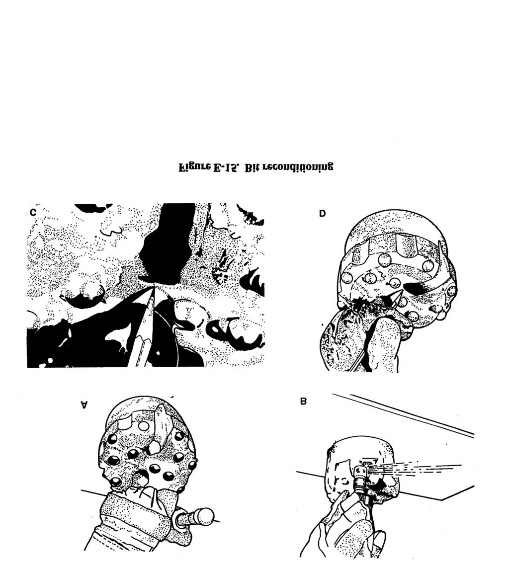
227 E-8
228 ACE Assistant Chief of Engineers AF Air Force AFI Air Force instruction AFP Air Force pamphlet AFSC Air Force Specialty Code air-foam-gel technique Adding foamer to a fluid in the same proportions as clear water to get a richer, more stable foam. air-lift method A pump-testing method that uses an air-lift pump, air-line method A procedure to measure the water level using an air line; the air line is copper tubing or galvanized pipe that is long enough to extend below the lowest water level being measured. air rotary driling A well-drilling method that uses compressed air as the circulating fluid. alligatoring A network of fine cracks and small carbide flecks on a bit that appear after hours of drilling in nonabrasive soft rock. alluvium Soils that are deposited by running water. alt attitude ant-mound-like openings. See qanat AO area of operations APOD aerial port of debarkation APOE aerial port of embarkation aquagel Commercial chemical agent added to mud drilling fluid to prevent it from freezing. See also barite; fibratex; gel-flake; impermex; micatex; smentex aquiclude Subsurface rock or soil unit, such as clay, shale, and unfractured igneous and metamorphic rock, that does not transmit water readily and cannot be used as a water-supply source. Glossary aquifer Saturated rock or soil unit, such as gravel, sand, sandstone, limestone, and fractured igneous and metamorphic rock, that has sufficient hydraulic conductivity to supply water for a well or spring. aquitard A unit that retards or slows the passage of water. AR Army regulation Ark Arkansas ARTEP Army Training and Evaluation Program attapuigite Commercially processed clay used for drilling in brackish or salty water. ATTN attention augered well A well that is bored using hand-or power-driven earth augers. AWWA American Water Works Association backwashing Well-development method. See also jetting method; gravity-outflow method; pressure-pumping method; pump-surge method; surge-block method ball-down method Installing screen using a special end fitting, bail-down placement A method of simultaneously placing the gravel pack and installing the screen. Barafos A white, granular sodium tetraphosphate thinner and dispersant added to drilling fluid to prevent mud from sticking to sand grains. barite Commercial chemical agent added to mud drilling fluid to prevent it from freezing. See also aquagel; fibratex; gel-flake; impermex; micatex; smentex barreling A wear pattern that causes the diameter of the bit body to exceed the gauge diameter of the buttons. basalt An igneous rock that is a very productive water bearer. Glossary-1
229 bentonite Commercially processed clay used for drilling; bentonite forms naturally from decomposition of volcanic ash, consists of aggregates of flat platelets, and contains sodium montmorillonite, which is important in building viscosity. body metal A type of bit failure. body wash Eroded body metal in bits. BOM bill of materials boundary indicators Characteristics that are indicative of local or regional groundwater flow systems. brass-jacket-type drive point Consists of a perforated pipe wrapped with wire mesh and covered with a perforated brass sheet. brass-tube-type drive point Consists of a brass tube slipped over perforated steel pipe for a rugged construction. cable jack A four-pronged receptacle located in the upper right comer of the panel on the electrical logging system. cable-tool method A very slow drilling method that can be used to penetrate rocky soil or moderately hard sedimentary rock; the drill used in this method does not require large amounts of drilling fluid. CAL calibrate CAL ADJUST (calibration adjustment) Located in the lower right-hand comer of the panel on the electrical logging system and used to zero the galvanometers when calibrating the instrument. carbide shear The most prevalent type of carbide breakage in bits casing ring and slip A device used to suspend the casing at the ground surface and for pulling pipe from the hole using jacks under each side of the casing ring. catchment Formation whine impervious rock underlies a zone of fractured rock or alluvium that serves as a reservoir for infiltrated water; a catchment can be a special type of aquifer. cathodic protection. See sacrificial anode CB construction battalion cc cubic centimeter(s) centrifugal pump A variable displacement pump in which water flows by the centrifugal force transmitted to the pump in designed channels of a rotating impeller. cfm cubic foot (feet) per minute cfs cubic foot (feet) per second circular-orifice meter A device used to measure discharge rates. circular-orifice method A procedure to measure discharge rates using a circular-orifice meter. closed-well method A compressed-air method that involves using compressed air to close the top of the well with a cap and by arranging the equipment so air pressure can buiid up inside the casing to force water out through the screen openings. cm cubic meter(s) compressed-air methods Rapid, effective welldevelopment methods. See also closed-well method; open-well method CON DET A wetting agent added to drilling fluid to increase the dispersion action of polyphosphates. confined aquifer An aquifer that is completely filled with water and is overlaid by a confining bed. confining bed Aquiclude that exists between aquifers, water moves only within the aquifer. consolidated deposit Rock that consists of mineral particles of different sizes and shapes. continuous permafrost A zone where permafrost will be thick with no unfrozen ground. See also discontinuous permafrost; permafrost continuous-slot drive point A screen with horizontal openings and one-piece welded construction and contains no internal perforated pipe to restrict the intake area. CONUS continental United States core barrel A double-tube sampler used to collect undisturbed soil samples in material that either contains gravel or is too hard for a thin-wall sample. CPM critical-path method Glossary-2
230 crop irrigation Surface indicator that shows the use of surface water or groundwater for agriculture. CSS combat service support CUR (current) A red plug receptacle used to connect the surface-current ground wire to the instrument. current switch The ON-OFF switch located directly below the function switch; the current switch is a momentary spring-return toggle switch. d depth DA Departmnt of the Army Darcy s Law Principle that describes the flow of groundwater. DC direct current Denisen sampler, See core barrel DD Department of Defense DHD down-hole drilling discharge Water that moves from one area into another. discontinuous permafrost A zone where permafrost will be thin and maybe absent on the south slopes of hills, in valley bottoms containing permeable alluvial material, and under surfaces that have been cleared of vegetation. See also continuous permafrost; permafrost dispersion treatment Adding dispersing agents to drilling fluid, backwashing, jetting water, or water standing in the well to counteract the tendency of mud to stick to sand grains. dissolution potential The possibility of developing high secondary permeability in a soluble rock because the rock dissolves through contact with groundwater. DMA Defense Mapping Agency DOD Department of Defense dolomite A carbonate rock that dissolves when carbon dioxide from the atmosphere and groundwater mix to form carbonic acid. double-casing placement A method of placing gravel using a temporary outer casing. drainage basin An area drained by a stream or river. See also hydrographic basin (local drainage basin); major river basin; regional river basin drawdown Measure of how much the water level near the well is lowered when the well is pumped. draw works Main drill-head hoists that are mechanically or hydraulically driven wire-line winches, drilling blind A condition that exists when a driller continues to drill when fluid circulation is lost, drive clamp Uused in driving easing or pipe and is attached to the square of the drill stem. drive head Device that is placed on the pipe to protect the threads the the driving blows of the drive clamps; a drive head is put on by unscrewing the bit, slipping the drive head over the drilling stem, and making up the joint again. drive monkey A weight that slides over the pipe and is used in the falling-weight method of driving a well. driven method Installing casing as with the borehole, the cable-tool, or driven-point well method. drive point Perforated pipe with a steel point at the lower end to breakthrough pebbles or thin, hard layers. drive shoe Device attached to the lower end of the pipe to prevent the pipe from crumpling while being driven; a drive shoe is threaded to fit the pipe or casing. dump-bailer method Placing grout in a casing using a dump-bailer machine. EAC echelons above corps electric-line method A procedure to measure the water level using an M-Scope. See also M-Scope electrode selector switch A five-position switch located directly above the ohmmeter on the electrical logging system. Glossary-3
231 elev elevation elevator (casing) A device used to handle pipe; the elevator is clamped around the pipe directly under the coupling. See also pin hook; sand line ENGR engineer evaporation Direct radiation from the sun that causes liquid at the surface of a body of water to change from a liquid to a vapor. evaporite Sedimentary rock that is generally capable of storing and transmitting groundwater but teds to dissolve in the water E-Z Mud A synthetic, inorganic polymer. F Fahrenheit fall-in Material that accumulates in the bottom of the borehole after circulation stops, falling weight Driving method that uses a steel driving bar attached to a rope; the bar falls freely inside the pipe and strikes the base of the drive point. feed drive Mechanism on a rotary rig that applies a downward thrust to the drill string. fibratex Commercial chemical agent added to mud drilling fluid to prevent it from freezing. See also aquagel; barite; gel-flake; irnpermex; micatex; smentex filter cake Solids from the drilling mud deposited on the borehole wall as the water phase is lost into the formation fish Portion of the drill string left in the borehole. See also fishing; string failure fishing An attempt to retrieve the portion of the drill string left in the borehole. See also fish string failure flow-meter method A procedure used to measure flow rate using a turbine-type flow meter. FM field manual FMF Fleet Marine Force foamer Substance used in air rotary drilling to enhance the air s ability to carry cuttings and reduce the velocity required to clean the borehole. foot piece A device at the end of an air pipe that breaks the air into small streams so that the bubbles formed will be as small as possible. formation stabilizer Material placed on the outside of the screen to help prevent deterioration of the annular space; using formation stabilizer is an alternative method to using gravel-pack material. fpm foot (feet) per minute ft foot (feet) ft/min foot (feet) per minute function switch A three-position selector switch located directly beneath the galvanometers on the electrical logging system. gal gallon(s) galvanometers A zero-centered micrometer on the electrical logging system. gel-flake Commercial chemical agent added to mud drilling fluid to prevent it from freezing. See also aqualgel; barite; fibratex; impermex; micatex; smentex gel strength Thickness of drilling mud at rest. geologic structure Feature, such as a fold, fracture, joint, or fault, that disrupts the continuity of rock units. geyser effect A result of denser mud in the anuular space flowing down the hole and forcing the clean drilling mud up the drill rods. going crooked deviated borehole GPH gallon(s) per hour GPM gallon(s) per minute gravel pack Artificial sand filter. gravity-outflow method A backwashing method that involves pouring water into the well rapidly to produce outflow through the screen openings. groundwater indicators Features that suggest the presence of groundwater. hand auger A device that consists of a shaft or pipe with a wooden handle at the top and a bit with curved blades at the bottom; a hand auger Glossary-4
232 can penetrate clay, silt, and those sands in which an open borehole will stand without caving. helical-rotor pump A positive-displacement, rotary-screw- or progressing-cavity-type pump designed for relatively low-capacity, high-lift wells that arc 4 inches or larger in diameter. HQ headquarters hydraulic conductivity A measurement of the relative flow of water through a subsurface material; the results of the measurement are related to the size and spacing of particles or grains in soils or to the number and size of fractures in rocks. hydrographic basin (local drainage basin) Subdivision of a regional river basin. See also drainage basin; major river basin; regional river basin hydraulic gradient Determines the direction of groundwater flow. hydrologic cycle The constant movement of water above, on, and below the earth s surface. ID inside diameter igneous rock Rock that forms when hot molten material (magma) cools or solidifies either inside the earth s crust or on the earth s surface (lava). See also lava; magma impermeable barriers Features (solid rock masses) through which groundwater cannot flow. impermex Commerical chemical agent added to mud drilling fluid to prevent it from freezing. See also aquagel; barite; fibratex; gel-flake; micatex; smentex in inch(es) infiltration Precipitation on land surfaces that seeps into the ground inside-tremie method Placing grout in the bottom of the hole through a tremie pipe that is set inside the casing. ISO International Standards Organization ITWD InternationaI Standards Organization/ air-transportable water drill. JCS Joint Chiefs of Staff jet-drive drilling A method of constructing small wells in cold climates; the wells are usually 2 inches in diameter and are drilled to a depth of 200 feet. jet pump A combination of a surface centrifugal pump, a down-hole nozzle and a venturi arrangement used in small diameter wells requiring a lift of 100 feet or less. jetted well A well that is dug using a high velocity stream of water. jetting method A backwashing method that involves using a jetting tool to remove caked drilling mud from the borehole wall; this method requires a large water supply. JOG Joint Operations Graphics karst topography Results from the dissolution of carbonate rocks by groundwater and is characterized by caves, sinkholes, closed depressions, and disappearing streams. kg kilogram(s) kg/m kilogram(s) per meter kv kilovolt(s) kw kilowatt(s) lag time The time it takes sample material to reach the surface during a depth-determination teat. lava Magma that cools or solidifies on the earth s surface. See also igneous rock; magma lb pound(s) lb/ft pound(s) per foot limestone A carbonate rock that dissolves when carbon dioxide from the atmosphere and groundwater mix to form carbonic acid. lithification The process by which sediments are converted to rock; lithifiiation includes compaction, consolidation, cementation and desiccation. LOG (logging) Position on the function switch on the electrical logging system. Glossary-5
233 logging cable A cable on the electrical logging system used to lower the probe into the weli. loss zone Area where grout is lost into the formation. lost circulation Volume loss of the drilling fluid returning to the surface. LPM liter(s) per minute LVS Service Logistical Vehicle Systems m meter(s) ma milliampere(s) magma Hot molten material. See also igneous rock; lava major river basin Largest member in the river basin grouping; the Mississippi River Basin is a major river basin. See also drainage basin; hydrographic basin; regional river basin Marsh funnel Device used to test mud viscosity; the funnel is 12 inches long and 6 inches in diameter, and it has a No 12 mesh strainer, a 1,500-ml cone, a 2-inch-long calibrated hardrubber orifice (inside diameter of 3/16 inch), and a 1,000-ml capacity cup. Marsh-funnel test Procedure routinely conducted to determine the thickness or apparent viscosity of drilling fluid. MEAPO Middle East/Africa Project Office measured-container method A procedure used to determine flow rate from a well or pump by measuring the time required to fill a container with a known volume. MEDEVAC medical evacuation metamorphic rock Igneous, sedimentary, or preexisting metamorphic rock that undergoes further transformation by changes in pressure, temperature or chemistry. micatex Commerical chemical agent added to mud drilling fluid to prevent it from freezing. See also aquagel, barite; fibratex; gel-flake; impermex; smentex min minute(s) ml milliliter(s) mm millimeter(s) MO Missouri monitoring well Small water well used for measuring water level, estimating well yield, and taking samples for quality analysis; monitoring wells are drilled next to permanent wells at specified intervals. mph mile(s) per hour MS Mississippi M-Scope Two-conductor, battery-powered indicator used to measure water levels. mud pump A positive-displacemenc doubleacting piston pump with capacities ranging from one to several hundred GPM at pressures up to several hundred psi. mud rotary drilling A well-drilling method that uses mud to circulate the drilling fluid during the drilling process. N no N/A not applicable NATO North Atlantic Treaty organization NAVFAC Naval Facilities Engineering Command NBC nuclear, biological chemical NCF naval construction force NCOIC noncommissioned officer m charge NMCB naval mobile construction battalion No number NSN national stock number OD outside diameter ohmmeter An instrument on the electrical logging system that is located directly above the CAL ADJUST; the ohmmeter indicates the earth resistivity in ohm-feet. open-hole method of installing casing Installing casing into a borehole one casing section at a time. open-hole method of installing screen Installing telescoping screen when the depth and thickness of the aquifer have been predetermined. open-hole placement A method of installing gravel-pack material m a well. Glossary-6
234 open-pipe method A procedure to measure discharge rates using a fully open pipe and measuring the distance the water stream travels parallel to the pipe at a 12-inch vertical drop. open-well method A compressed-air method that involves establishing the surging cycle by pumping from the well with an air lift and by dropping the air pipe suddenly to cutoff the pumping action. outside-tremie method Placing grout outside the casing using a tremie pipe; this method is not recommended for depths greater than 100 feet. P pamphlet particle slip Downward movement of an object through fluid. pendulum effect Action of creating a straight borehole from a weighted drill string and bit. perched aquifer An aquifer that lies above an unconfined aquifer and is separated from the surrounding groundwater table by a confining layer. percussion drilling A method of drilling that involves crushing by impact from the teeth of the drill bit percussion drilling for water wells uses down-hole, pneumatic-percussion hammer drills. permafrost Permanently frozen rock and soil that is widespread in the Arctic north of 50 N latitude; permafrost is either continuous or discontinuous. See also continuous permafrost; discontinuous permafrost permeability The capacity of a porous rock or soil to transmit a fluid. ph Negative logarithm of the effective hydrogen-ion concentration or hydrogen-ion activity in gram equivalents per liter used in expressing acidity and alkalinity on a scale of O to 14 with 7 representing neutrality. pin hook Device used with an elevator to lift very heavy strings of pipe; the hook is attached to the rope socket on the drilling line. See also elevator (casing); sand line pipe clamp A device used to hold the pipe at any position in the hole during drilling operations. pipe tong Device used to tighten 6- and 8-inch drive pipe. pitcher pump A surface-mounted, reciprocating or single-acting piston pump. pitting A condition on bits that is caused by the presence of foreign material such as rock cutting or the use of rock drill oil with a high sulphur content. playas Dry lake beds comprised mainly of clay and located in intermountain valleys. POL petroleum, oils, and lubricants polymer A water-based, organic, inorganic, natural, synthetic, or synthetically formulated additive; polymers are formulated for various drilling fluid purposes and can be used alone or to enhance clay muds. Poly-Sal Synthetic, inorganic polymer. See also polymer popping A condition whereby a carbide insert will pop clean from its socket if the drill string is not properly fed up in the hole. population distribution Surface indicator that could indicate water availability because of population density. porosity Voids in soil and rocks. POT (potentiometer) A black plug receptacle used to connect the surface-potential ground wire to the instrument. power auger A device that is rotated, raised, and lowered by a power-driven mechanism; a power auger has a depth limit of about 10 feet and can be used only in areas where the water table is close to the surface. ppm parts per million precipitation Moisture released from clouds to the earth in the form of rain, sleet, hail, or snow. pressure-pumping method A backwashing method that involves capping the casing and pumping water into the well under pressure. probe selector switch A switch on the electrical logging system that is located directly below the SP shutoff switch on units modified for mud logging. psi pound(s) per square inch psig pound(s) per square inch gauge Glossary-7
235 PTO power takeoff pull-back method A way of installing telescoping screen. pulldown. See feed drive pump-surge method A backwashing method that involves alternately pumping water to the surface and letting water run back into the well through the pump-column pipe. push-tube A method of collecting undisturbed soil samples; this method uses thin-wall, freed-piston samplers in very soft to stiff clays, silts, and sands that do not contain appreciable amounts of gravel. PVC polyvinyl chloride qanat A man-made, gently inclined underground channel that allows groundwater to flow from alluvial gravels at the base of hills to a dry lowland; qanats appear as a series of ant-mound-like openings that run in a straight line and act as air shafts for a channel. qt quart(s) Quick-Gel Wyoming-type bentonite drilling fluid used for mixing mud recharge Water that infiltrates the soil. recharge area Area where the groundwater reservoir is replenished. RED HORSE rapid engineer deployable, heavy operational repair squadron. regional river basin Subdivision of a major river basin; the Missouri River Basin is a regional river basin of the Mississippi River Basin. See also drainage basin, hydrographic basin; major river basin reservoir indicators Characteristics in soils, rocks, and landforms that define the ability of an area to store and transmit groundwater but which do not directly indicate the presence of groundwater. Revert A natural, organic polymer fluid derived from the guar plant. See also polymer RH-1 An air-transportable RED HORSE echelon composed of 16 people and ready for deployment 12 hours after notification. RH-2 An air-transportable RED HORSE echelon composed of 93 people and ready for deployment 48 hours after notification. RH-3 A RED HORSE echelon composed of 295 people and ready for deployment six days after notification ringing off Fatigue failure in the drill-rod joints caused by excessive torque or thrust or by borehole deviation. riparian vegetation Dense strands of vegetation along stream channels. rivers. See streams and rivers rock development A well-development method used in rock formations that involves combining jetting with air-lift pumping to wash out fine cuttings, silt, and clay. rotary pump A pump that uses a system of rotating gears to create a suction at the inlet and force a water stream out of the discharge. rotary table Rotating platform on a rotary rig that transmits torque to the drill rod through the kelly. ROWPU reverse osmosis water purification units RPM revolution(s) per minute rung off See string failure runoff Precipitation on land surfaces that flows along the surface. S3 Operations and Training Officer (US Army) sacrificial anode A simple method of protecting metal casing from corrosion by connecting a galvanically active metal bar to the casing. salt encrustation Surface indicator that often occurs in playas and is indicative of saline groundwater. saltwater encroachment Movement of saltwater into zones previously occupied by freshwater. saltwater intrusion Invasion of salt water into freshwater during pumping. sanded in A condition that exists when the string becomes stuck when cuttings collect on the bit and collar shoulder. Glossary-8
236 sand line Device used with the elevator for lifting one or two half lengths of pipe. See also elevator (casing); pin hook sandstone Consolidated or cemented sand. saturated thickness Distance between the top of the groundwater and the bottom of the aquifer. SC supply catalog SCFM sea level cubic foot (feet) per minute semipermeable barriers Features (faults or fractured rock masses) that restrict flow but do not act as a complete barrier. sedimentary rock Rocks that are composed of sediments that are converted to rock through compaction cementation or crystallization. self-jetting method Digging a jetted well by sinking a continuous-slot-, brass-jacket-, or jet-head-tapering-type well point. self-potential potentiometer The instrument in the electrical logging system that balances out the SP that exists between any pair of potential electrodes. self-priming pump A pump with a priming chamber that makes repriming unnecessary when the pump is stopped for any reason other than au intentional draining. semipermeable barriers Features (faults or fractured rock masses) that restrict water flow but do not act as complete barriers. shale Fine-grained sedimentary rock that does not store much groundwater and does not transmit large quantities of groundwater. single-string method of installing casing Installing casing and screen (already joined) in a single assembly. single-string method of installing screen. See single-string method of installing casing sinker rod An insulated device that can be attached with a leather thong to the probe on the electrical logging system if more weight is needed to carry the probe to the bottom of a well. smentex Commercial chemical agent added to mud drilling fluid to prevent it from freezing. See also aquagel; barite; fibratex; gel-flake; impermex; micatex snow-melt pattern Surface indicator that can provide evidence of recharge areas and directions of groundwater flow. soil moisture Surface indicator that can provide some indication of recharge and discharge areas; soil moisture content is related to local rainfall and to grain size. SOP standing operating procedures SP spontaneous potential specific retention Water that cannot be pumped out of a well. specific yield Water that can be pumped from a well. spring Effluence of groundwater occurring where the water table intercepts the ground surface; a spring is a good surface indicator of the presence of shallow groundwater occurrences. SP polarity-reversing switch A switch on the electrical logging system that is located directly below the SP potentiometer the switch shows the polarity of the particular cable electrode being used. SP shutoff switch A spring-return switch on the electrical logging system that is located in the upper left comer of the panel; this switch automatically shuts off the l-1/2-volt C-battery when the instrument lid is closed. spudding Raising or lowering the drill string. spudding in Starting the borehole. squeezing See swelling soil Sr specific retention stabilizers Items, such as drill collars, used on the drill string during drilling operations. STANAG Standardization Agreement STD standard STP Soldier Training Publication straight pumping A well-completion method that uses a pitcher-spout hand pump. Glossary-9
237 streams and rivers Surface indicators that are usually recharge areas in arid regions and may be recharge or discharge areas in temperate climates; areas adjacent to streams are considered good locations for wells but are not always the best available areas for water wells because of soil content. string failure A condition that exists when the drill string parts, leaving a portion in the borehole the drill string is rung off. See also fish; fishing submergence The proportion (percentage) of the length of the air pipe that is submerged below the pumping level. submersible pump A centrifugal pump closely coupled with an electric motor that can be operated underwater, submersible-pump method A pump-testing method that uses a submersible pump to pump test the water well. surface indicator Feature that suggests the presence of groundwater. surface-water divide Boundary between groundwater flow systems. surge-block method A backwashing method that involves developing a well by surging water up and down the casing with a surge block or plunger. swelling soil (squeezing) In-hole effects of shale or clay that absorb water from the drilling fluid Sy specific yield TAC Terrain Analysis Center TAD Transatlantic Division tag-along compressor auxiliary compressor tape method Procedure to measure the depth to the static level in a shallow well. TEC united states Army corps of Engineers Topographic Engineering Center TM technical manual TN Tennessee TO technical manual TO theater of operations TOA table of allowances top head A mechanism on a rotary rig that moves down along the rig mast as the boring is advanced and is raised to the top of the mast to add a length of drill pipe; the top-head drive uses a power swivel. TRADOC United States Army Training and Doctrine Command transmissivity The product of hydraulic conductivity and the saturated thickness expressed in gallons per day per foot of aquifer width. transpiration Water that Wrens to the atmosphere from plants. tremie placement Placing gravel-pack material using a tremie pipe. tricone bit A bit that consists of three conshaped rollers with steel teeth milled into the surfaces. turbine pump A shaft-driven, multistage, centrifugal pump containing several impellers or bowl assemblies. uncased-interval method Installing casing in wells located in rock formations. unconfined aquifer An aquifer that is partly filled with water, has fluctuating water levels, and can receive direct recharge from percolating surface water. unconsolidated deposit Consists of weathered rock particles of varying materials end sizes. unscreened well A well in competent rock that does not require a screen; the aquifer is tapped through numerous, irregularly spaced fractures. US United States (of America) USAF United States Air Force USGS United States Geological Survey vegetation type Surface indicator that can help define the location of recharge and discharge areas end groundwater. viscosity Relates to true (Newtonian) fluids such as water; viscosity is a proportional constant between sheer stress and rate in laminar flow. Glossary-10
238 FM 5-484/NAWAC P-1065/AFMAN wall stuck A condition that exists when the alignment of a fine-grained soil or shale hole deviates significantly and the drill pipe wallows into the wall. washdown method Installing screen in an aquifer that is composed of fine to coarse sand with little or no gravel. wash-in method Installing casing by advancing the borehole for an expedient jetted-well construction. water-table wells Wells drilled into an unconfined aquifer. WDRT Water Detection Response Team WDS well-drilling system well probe A device on the electrical logging system that consists of one brass current electrode and three lead-oxide potential electrodes. WES United States Army Corps of Engineers Waterways Experirment Station wetlands Marshes, bogs, and swamps that arc indicative of very shallow groundwater. WRDB Water Resources Data Base XS extra strength Y yes yield Volume of water discharged from a well per unit of time when water is being pumped or is flowing freely. yield point Mud quality broadly included m viscosity. Glossary-11
239 References SOURCES USED These are the sources quoted or paraphrased in this publication. International Standardization Agreement STANAG 2885 ENGR (Edition 2). Emergency Supply of Water in War. 9 November Military Publications FM Terrain Analysis. 11 July FM Engineer Field Data. 14 September FM Engineer Operations Echelons Above Corps. 7 March TM Rigging. 3 October Nonmilitary Publications Baroid Properties and Performance of Drilling Muds. Baroid Drilling Fluids, Inc. Houston, Texas. Catalog no. WW Geology and Geophysics for Military Well Drillers. Geotechnical Laboratory, US Army Engineers Waterways Experiment Station. Vicksburg, Mississippi. Groundwater Atlas of the United States: Hydrologic Investigations Atlas. Department of the Interior USGS. Denver, Colorado. Chapter 730-A. Introductory material and nationwide summaries (Segment no. 0). Chapter 730-B. California, Nevada (Segment no. 1). Chapter 730-C. Arizona, Colorado, New Mexico, Utah (Segment no. 2). Chapter 730-D. Kansas, Missouri, Nebraska (Segment no. 3). Chapter 730-E. Oklahoma, Texas (Segment no. 4). Chapter 730-F. Arkansas, Louisiana, Mississippi (Segment no. 5). Chapter 730-G. Alabama, Florida, Georgia, South Carolina (Segment no. 6). Chapter 730-H. Idaho, Oregon, Washington (Segment no. 7). Chapter Montana, North Dakota, South Dakota, Wyoming (Segment no. 8). Chapter 730-J. Iowa, Michigan, Minnesota, Wisconsin (Segment no. 9). Chapter 730-K. Illinois, Indiana, Kentucky, Ohio, Tennessee (Segment no. 10). Chapter 730-L. Delaware, Maryland, New Jersey, North Carolina, Pennsylvania, Virginia, West References-1
240 FM 5-484/NAVFAC P-l065/AFMAN Virginia (Segment no, 11), Chapter 730-M. Connecticut, Maine, Massachusetts, New Hampshire, New York, Rhode Island, Vermont (Segment no, 12). Chapter 730-N. Alaska, Hawaii, Puerto Rico (Segment no. 13). Ground Water and Wells. Third Edition. Johnson Filtration Systems, Inc. St. Paul, Minnesota. ISBN , Percusion Drilling Equipment Operation and Maintenance Manual. (Catalog no. M500-2.) Mission Drilling Products Division, TRW Energy Products Group. Houston, Texas Techniques of Water-Resources Investigations of the United States Geological Survey. Applications of Borehole Geophysics to Water-Resources Investigations. Book no. 2. US Geological Survey. Arlington, Virginia. The Button Bit vs The Rock. (Publication Form no. 769-l.) Ingersoll-Rand Company. Roanoke, Virginia. Water Well Manual. U.C. Gibson and R.D. Singer. Premier Press, California DOCUMENTS NEEDED These documents must be available to the users of this publication. DD Form Well Driller s Log. October DD Form Piping and Casing Log. October DD Form 2680, Military Water Well Completion Summary Report. October DA Form Recommended Changes to Publications and Blank Forms, February DOD Defense Mapping Agency Catalog of Maps, Charts, and Related Products, Part 3 V. FM Explosives and Demolitions. 15 June FM Military Soils Engineering. 23 December TM Geology. 8 July TM , Dewatering and Groundwater Control. 15 November 1983 w/change 1, June TM Operating and Maintenance Instructions for Drilling System, Well Rotary, Truck Mounted, Air Transportable, 600 Feet Capacity, Model Number LP March 1989 w/change 1, 1 September STP 5-62J12-SM-TG. Soldier s Manual and Trainer s Guide, MOS 62J. General Construction Equipment Operator, Skill Levels 1/2. 15 October STP 5-62N34-SM-TG. Construction Equipment Supervisor Soldier s Manual and Trainer s Guide. MOS 62N, Skill Levels 3/4. 21 February References-2
241 SC CL-E01. Pneumatic Tool and Compressor Outfit, 250 CFM; Truck Mounted. 14 June 1974 AFI Civil Engineering RED HORSE Squadron. April 1983 API US Air Force Mishap Prevention Program. March AFT Air Force Occupational Safety Fire Prevention and Health Program. May TO lc-130a-9. Cargo Loading Manual. 16 June 1980 w/changes 1 through 8, 5 December A1OO-66. American Water Baltimore Military Publications Works Association Standard for Deep Wells. Waverly Press, READINGS RECOMMENDED AR Enlisted Personnel Management System. 15 September AR Policies and Procedures for Property Accountability. 31 January AR Army Materiel Maintenance Policy and Retail Maintenance Operations. 27 September FM Terrain Analysis. 11 July 1990 w/change 1, September FM Engineer Combat Operations. 22 November FM General Engineering. 12 November FM Construction Surveying. 4 January FM Construction Management. 17 February 1987 w/ change 1, April FM Drainage. 2 December FM Earthmoving Operations. 30 September FM Military Leadership. 31 July FM Battle Focused Training. 30 September 1990 FM l/AFP 93-4, Vol I. Planning and Design of Roads, Airfields, and Heliports in the Theater of Operations (Road Design). To be published withing 6 months. FM /AFP 93-4, Vol II. Planning and Design of Roads, Airfields, and Heliports in the Theater of Operations (Airfield Design). To be published withing 6 months. ARTEP Engineer Cellular Teams. 30 July Nonmilitary Publications Applications of Electrical Logging to Water Well Problems. F. L. Bryan. Water Well Journal, 4:1, References-3
242 Application of Electrical and Radioactive Well Logging to Ground-Water Hydrology. E. P. Patten and G. D. Bennett. US Geological Survey Water Supply Paper 1544 D Electric Logging Applied to Groundwater Exploration. P. H. Jones and T. B. Buford. Geophysics, 16:1. January Electrical Well Logging. H. Guyed. The Oil Weekly, a series of articles published from August 7 to December 4, Interpretation of Electric and Gamma Ray Logs in Water Wells. H. Guyed. American Geophysics Union. Technical Paper. Mandrel Industries Inc. Houston, Texas Investigation of Ground Water Supplies with Electrical Well Logs. H. Guyed. Water Well Journal. May Investigation of Groundwater Supplies with Electric Well Logs. T. S. Morris. Water Well Journal. May-June The Quantitative Aspects of Electric Lag Interpretation. J. E. Walstrom. Trans. Am. Inst. Min. and Met. Engrs., Vol Well Drilling Manual. National Water Well. Dublin, Ohio. ISBN Well Drilling Operations. National Water Well. Dublin, Ohio. ISBN Well Site Geologists Handbook. Donald McPhater. Tulsa, Oklahoma. ISBN References-4

243

244

245

246
247
248


249 Index-1 FM 5-484/NAVFAC P-1065/AFMAN
250 Index-2
251 Index-3 FM 5-484/NAVFAC P-1065/AFMAN
252 Index-4

253 Index-5 FM 5-484/NAVFAC P-1065/AFMAN
254 Index-6
255 Index-7 FM 5-484/NAVFAC P-1065/AFMAN
256 Index-8
257 Index-9 FM 5-484/NAVFAC P-1065/AFMAN
258 Index-10
Movement and Storage of Groundwater The Hydrosphere
 Movement and Storage of Groundwater The Hydrosphere The water on and in Earth s crust makes up the hydrosphere. About 97 percent of the hydrosphere is contained in the oceans. The water contained by landmasses
CHAPTER 13 OUTLINE The Hydrologic Cycle and Groundwater. Hydrologic cycle. Hydrologic cycle cont.
 CHAPTER 13 OUTLINE The Hydrologic Cycle and Groundwater Does not contain complete lecture notes. To be used to help organize lecture notes and home/test studies. Hydrologic cycle The hydrologic cycle is
General Groundwater Concepts
 General Groundwater Concepts Hydrologic Cycle All water on the surface of the earth and underground are part of the hydrologic cycle (Figure 1), driven by natural processes that constantly transform water
Groundwater. Importance of Groundwater. The Water Table. Geol 104: Groundwater
 Groundwater Subsurface water contained in soil and bedrock. There is ~ 60 times as much water underground than in freshwater streams and lakes. Source of groundwater is rain and snow. Represents the infiltration
Groundwater Earth 9th Edition Chapter 17 Mass wasting: summary in haiku form Importance of groundwater Importance of groundwater
 1 2 3 4 5 6 7 8 9 10 11 Groundwater Earth 9 th Edition Chapter 17 Geology 100 Mass wasting: summary in haiku form The grass is greener over the septic system said Erma Bombeck. Importance of groundwater
Ground Water Chapter 11
 Ground Water Chapter 11 How does water get underground? How is water stored underground? How does water move? How do we find it? Why we need to protect it. Lake Powell. Water levels are decreasing every
global distribution of water!
 groundwater! hydrologic cycle! 2 global distribution of water! Source Volume Percent Ocean 97.2000 Glaciers and other ice 2.1500 Ground Water 0.6100 Lakes fresh 0.0090 saline 0.0080 Soil Moisture 0.0050
Hydrologic Cycle. Rain Shadow:
 Hydrologic Cycle The cyclical movement of water from the ocean to the atmosphere by evaporation, to the surface through precipitation, to streams through runoff and groundwater, and back to the ocean.
Groundwater 3/16/2010. GG22A: GEOSPHERE & HYDROSPHERE Hydrology
 GG22A: GEOSPHERE & HYDROSPHERE Hydrology Definitions Groundwater Subsurface water in soil or rock that is fully saturated. Aquifer Contains enough saturated material to yield significant quantities of
Groundwater basics. Groundwater and surface water: a single resource. Pore Spaces. Simplified View
 Groundwater and surface water: a single resource Santa Cruz River, Tucson Groundwater basics Groundwater is water found within the pore spaces of geologic material beneath the surface of the Earth. It
Groundwater and surface water: a single resource. Santa Cruz River, Tucson
 Groundwater and surface water: a single resource Santa Cruz River, Tucson 1942 1989 1 Groundwater basics Groundwater is water found within the pore spaces of geologic material beneath the surface of the
Introduction to Groundwater
 Introduction to Groundwater Unit Essential Questions: How does the Earth cycle its water through its major reservoirs? How does society s use of resources affect water quality? Presentation Objectives:
Groundwater. Groundwater Movement. Groundwater Movement Recharge: the infiltration of water into any subsurface formation.
 On March 22, 2014, a major landslide occurred near Oso, Washington. Death toll currently at 30, with 15 still missing. Groundwater Before and After Swipe http://bit.ly/pen1jt N. Fork Stillaguamish River
ENGINEERING HYDROLOGY
 ENGINEERING HYDROLOGY Prof. Rajesh Bhagat Asst. Professor Civil Engineering Department Yeshwantrao Chavan College Of Engineering Nagpur B. E. (Civil Engg.) M. Tech. (Enviro. Engg.) GCOE, Amravati VNIT,
Groundwater. Chapter 10 11/22/2011. I. Importance of groundwater
 Groundwater Chapter 10 I. Importance of groundwater A. Groundwater is water found in the pores of soil and sediment, plus narrow fractures in bedrock B. Where is fresh water - 2 % of all water is fresh
GROUNDWATER BASICS SUBJECTS: TIME: MATERIALS: OBJECTIVES Math (Advanced), Science (Physics) 1 class period
, Science (Physics) 1 class period") 9-12 GROUNDWATER BASICS SUBJECTS: Math (Advanced), Science (Physics) TIME: 1 class period MATERIALS: calculator paper pencil student sheet and figures OBJECTIVES The student will do the following: 1. Compute
9-12 GROUNDWATER BASICS SUBJECTS: Math (Advanced), Science (Physics) TIME: 1 class period MATERIALS: calculator paper pencil student sheet and figures OBJECTIVES The student will do the following: 1. Compute
Water Cycle. Are you really drinking the same water as the caveman?
 Water Cycle Are you really drinking the same water as the caveman? Water Cycle Water is always on the move. Rain falling where you live may have been water in the ocean just days before. And the water
East Maui Watershed Partnership Adapted from Utah State University and University of Wisconsin Ground Water Project Ages 7 th -Adult
 INTRODUCTION What is groundwater? Water contained in saturated soil and rock materials below the surface of the earth. It is not NEW water, but is recycled water through the hydraulic cycle. The source
The Hydrologic Cycle and Groundwater
 CHAPTER 17 The Hydrologic Cycle and Groundwater Chapter Summary The hydrologic cycle is a flowchart or model for the distribution and movements of water on and below the surface of the Earth. The major
EES 1001 Lab 9 Groundwater
 EES 1001 Lab 9 Groundwater Water that seeps into the ground, and is pulled down by gravity through void spaces (*see below) in the soil and bedrock eventually percolates down to a saturated zone, a water-logged
Introduction to Groundwater Science
 Introduction to Groundwater Science Laila Kasuri LUMS - WIT Overview Groundwater Hydrology and Basic Terms Groundwater Movement and Flow Groundwater Challenges Groundwater Management What is Groundwater
FACT FLASH. 5: Groundwater. What is groundwater? How does the ground store water? Fact Flash 5: Groundwater
 FACT FLASH 5: Groundwater What is groundwater? Groundwater is fresh water (from rain or melting ice and snow) that soaks into the soil and is stored in the tiny spaces (pores) between rocks and particles
Water Resources. The Water Cycle. Section 1. Key Terms surface water river system watershed groundwater aquifer porosity permeability recharge zone
 Water Resources The next time you drink a glass of water, think about where the water came from. Did you know that some of the water in your glass may have been part of a rainstorm that pounded Earth long
GLY 155 Introduction to Physical Geology, W. Altermann. Grotzinger Jordan. Understanding Earth. Sixth Edition
 Grotzinger Jordan Understanding Earth Sixth Edition Chapter 17: THE HYDROLOGIC CYCLE AND GROUNDWATER 2011 by W. H. Freeman and Company Chapter 17 The Hydrologic Cycle and Groundwater 1 About the Hydrologic
True False Click and Drag Artesian wells are naturally under pressure and require no additional pumps to get the water out of the ground.
 True False Click and Drag Artesian wells are naturally under pressure and require no additional pumps to get the water out of the ground. Groundwater recharge is the water from infiltration Groundwater
Hydrogeology 101 3/7/2011
 Hydrogeology 101 W. Richard Laton, Ph.D., PG, CPG Associate Professor of Hydrogeology California State University, Fullerton Department of Geological Sciences 1 Hydrogeology 101 The objective is to obtain
Hydrogeology of Prince Edward Island
 Hydrogeology of Prince Edward Island General Characteristics and Groundwater on Prince Edward Island General Characteristics and Key Issues Issues PEI Dept. of Environment, Energy and Forestry 9/29/2009
7/3/2018. Groundwater
 1 2 3 4 5 6 7 8 9 10 11 12 Groundwater Earth Chapter 17 Chapter 17 Groundwater Importance of Groundwater Groundwater is water found in the pores of soil and sediment, plus narrow fractures in bedrock Groundwater
Hydrologic Cycle. Water Cycle. Groundwater
 Water Cycle, Groundwater, Water Pollution Hydrologic Cycle Distribution/Cycle Animation http://www.mnforsustain.org/water_climate_global_water_cycle_study.htm Water Cycle 86% of evaporation from sea surface
The Hydrologic Cycle (with emphasis on groundwater)
") The Hydrologic Cycle (with emphasis on groundwater) The Hydrologic Cycle (viewed in series of steps) 1. Water evaporates from bodies of surface water and from land 2. As moist air is lifted, it cools and
The Hydrologic Cycle (with emphasis on groundwater) The Hydrologic Cycle (viewed in series of steps) 1. Water evaporates from bodies of surface water and from land 2. As moist air is lifted, it cools and
Topic 3, Subtopic A of Review Handbook or Chapter 10 of Earth Science Book. 97% of Earth s water is found as saltwater in Earth s oceans.
 Topic 3, Subtopic A of Review Handbook or Chapter 10 of Earth Science Book Groundwater 97% of Earth s water is found as saltwater in Earth s oceans. That leaves only 3% for freshwater! But 90% of the freshwater
Freshwater. 260 Points Total
 9 SURFACE WATER SECTION 9.1 Surface Water Movement In your textbook, read about surface water and the way in which it moves sediment. Complete each statement. (13 points) 1. An excessive amount of water
groundwater. Because watersheds are complex systems, each tends to respond differently to natural or human activities.
 The private development of Altos del María is located at an altitude between 550 and 1,000 meters above sea level in the environmentally sensitive Cordillera Central of Panama that separates the Pacific
Supplemental Guide II-Delineations
 Supplemental Guide II-Delineations Contents Source Water Protection Area Delineation... 1 Delineation Criteria for Systems Using Groundwater Sources... 2 Time of Travel... 4 Flow Boundaries... 4 Delineation
University of Arizona Department of Hydrology and Water Resources Dr. Marek Zreda
 University of Arizona Department of Hydrology and Water Resources Dr. Marek Zreda HWR431/531 - Hydrogeology Final exam - 12 May 1997 Open books and notes The test contains 8 problems on 7 pages. Read the
WATER-WELL DRILLING OPERATIONS
 U.S. NAVY NTRP 4-04.2.13 U.S. ARMY FM 3-34.469 U.S. AIR FORCE AFMAN 32-1072 WATER-WELL DRILLING OPERATIONS EDITION DECEMBER 2008 DISTRIBUTION RESTRICTION: APPROVED FOR PUBLIC RELEASE; DISTRIBUTION IS UNLIMITED.
Lecture 20: Groundwater Introduction
 Lecture 20: Groundwater Introduction Key Questions for Groundwater 1. What is an aquifer? 2. What is an unconfined aquifer? 3. What is groundwater recharge? 4. What is porosity? What determines the magnitude
Design Guideline for Gravity Systems in Soil Type 1. January 2009
 Design Guideline for Gravity Systems in Soil Type 1 January 2009 This page is intentionally blank. Design Guideline for Gravity Systems in Soil Type 1 January 2009 For information or additional copies
CHAPTER ONE : INTRODUCTION
 CHAPTER ONE : INTRODUCTION WHAT IS THE HYDROLOGY? The Hydrology means the science of water. It is the science that deals with the occurrence, circulation and distribution of water of the earth and earth
BAEN 673 / February 18, 2016 Hydrologic Processes
 BAEN 673 / February 18, 2016 Hydrologic Processes Assignment: HW#7 Next class lecture in AEPM 104 Today s topics SWAT exercise #2 The SWAT model review paper Hydrologic processes The Hydrologic Processes
COPYRIGHTED MATERIAL. Contents PART ONE: THEORY...1. Preface to the Third Edition xiii. About the Authors xv. Acknowledgements xvii
 Preface to the Third Edition xiii About the Authors xv Acknowledgements xvii Contents PART ONE: THEORY...1 1. Groundwater in Construction...3 1.1 Groundwater in the Hydrologic Cycle 3 1.2 Origins of Dewatering
RUNNING WATER AND GROUNDWATER
 NAME RUNNING WATER AND GROUNDWATER I. Introduction In this exercise we will investigate various features associated with streams and groundwater. Our drinking water ultimately comes from either streams
Understanding the Water System
 W Water Is a Natural Resource Understanding the Water System Cost WATER QUALITY in KENTUCKY The Water Cycle Figure 1. Trends in Water Withdrawals and Population, 1950 to 1995. Millions of People/Billion
POND SEALING OR LINING COMPACTED SOIL TREATMENT
 NATURAL RESOURCES CONSERVATION SERVICE CONSERVATION PRACTICE STANDARD POND SEALING OR LINING COMPACTED SOIL TREATMENT CODE 520 (FT. 2 ) DEFINITION A liner for an impoundment constructed using compacted
The soil is a very. The soil can. The manure. Soil Characteristics. effective manure treatment system if manures are applied at the proper rate.
 The soil is a very effective manure treatment system if manures are applied at the proper rate. The soil can filter pollutants and prevent them from reaching groundwater. The manure application rate should
The Water Cycle. 1. The diagram below is a cross-sectional view of rain falling on a farm field and then moving to the water table.
 1. The diagram below is a cross-sectional view of rain falling on a farm field and then moving to the water table. Which word best describes the movement of the rainwater through zone A? A. runoff B. saturation
Understanding Earth Fifth Edition
 Understanding Earth Fifth Edition Grotzinger Jordan Press Siever Chapter 17: THE HYDROLOGIC CYCLE AND GROUNDWATER Lecturer: H Mohammadzadeh Assistant professors, Department of Geology, FUM Copyright 2007
Florida s Aquifers Florida s Great Unseen Water Resources
 Southwest Florida Water Management District West-Central Florida s Aquifers Florida s Great Unseen Water Resources The abundance of Florida s freshwater resources provides a great attraction for residents
Water Sources. Martin Wafler, seecon international gmbh. Water Sources
 Martin Wafler, seecon international gmbh 1 Copyright & Disclaimer Copy it, adapt it, use it but acknowledge the source! Copyright Included in the SSWM Toolbox are materials from various organisations and
D.G.S.W. Pitakumbura Manager (Groundwater Studies) Groundwater Section NWS&DB. Groundwater recharge or deep drainage or
 Groundwater Section NWS&DB. Groundwater recharge or deep drainage or") Groundwater Recharge and Extraction Techniques D.G.S.W. Pitakumbura Manager (Groundwater Studies) Groundwater Section NWS&DB What is Groundwater Recharge Groundwater recharge or deep drainage or deep percolation
Groundwater Recharge and Extraction Techniques D.G.S.W. Pitakumbura Manager (Groundwater Studies) Groundwater Section NWS&DB What is Groundwater Recharge Groundwater recharge or deep drainage or deep percolation
Overview. Students will...
 Overview Students will... Understand the interaction between ground water and surface water. Observe the difference between a permeable layer and an impermeable layer in an aquifer. See how water is stored
Introduction. Welcome to the Belgium Study Abroad Program. Courses:
 Introduction Welcome to the Belgium Study Abroad Program Courses: AGSM 335: Soil and Water Management BAEN 460: Principals of Environmental Hydrology BAEN 460 / AGSM 335 Combined lecture and HW sessions
Ground Water, Wells and the Summer of 1999
 Maine Geologic Facts and Localities October, 1999 Ground Water, Wells and the Summer of 1999 Text by Marc C. Loiselle, Department of Agriculture, Conservation & Forestry 1 Introduction The summer of 1999
Science Olympiad. Mentor Invitational Hydrogeology ANSWER KEY. Name(s): School Name: Point Totals
: School Name: Point Totals") Science Olympiad Mentor Invitational Hydrogeology ANSWER KEY Team Number: Raw Score: Rank: Name(s): School Name: Point Totals Possible Part 1: Groundwater Concepts and Vocabulary 30 Part 2: The Hydrogeology
Science Olympiad Mentor Invitational Hydrogeology ANSWER KEY Team Number: Raw Score: Rank: Name(s): School Name: Point Totals Possible Part 1: Groundwater Concepts and Vocabulary 30 Part 2: The Hydrogeology
Chapter 2. Reservoir Rock and Fluid Properties
 Chapter 2 Reservoir Rock and Fluid Properties Table of Contents Pages 1. Introduction... 3 2. Rock and Minerals... 3 3. Porosity... 4 3.1. Porosity Classification... 6 3.2. Range of porosity values for
Groundwater Investigations for CCR Landfills in Karst Terrain
 Groundwater Investigations for CCR Landfills in Karst Terrain Justin Brown, RG, GeoEngineers, Inc. Chris Hickman, PG, Jacobs Engineering Coal Ash Regulatory History 1978: Fossil fuel combustion waste was
WASA Quiz Review. Chapter 2
 WASA Quiz Review Chapter 2 Question#1 What is surface runoff? part of the water cycle that flows over land as surface water instead of being absorbed into groundwater or evaporating Question #2 What are
GY 111 Lecture Note Series Groundwater and Hydrogeology
 GY 111 Lecture Notes D. Haywick (2008-09) 1 GY 111 Lecture Note Series Groundwater and Hydrogeology Lecture Goals A) The hydrologic cycle B) Groundwater dynamics C) Mapping groundwater (done in class not
1.0 Introduction. 1.1 The Stream Depletion Issue. 1.2 Purpose of the Guidelines
 Guidelines for the Assessment of Groundwater Abstraction Effects on 1.0 Introduction 1.1 The Stream Depletion Issue The management of water resources has often focussed on groundwater and surface water
Water Resources on PEI: an overview and brief discussion of challenges
 Water Resources on PEI: an overview and brief discussion of challenges Components: Components and links Atmospheric water Surface water (including glacial water) Groundwater Links: Precipitation (atm(
Water is a solid, liquid, & gas. 71% of earth s surface is water. Our body is two-thirds water. Fresh water water that is not salty and has little or
 Water is a solid, liquid, & gas. 71% of earth s surface is water. Our body is two-thirds water. Fresh water water that is not salty and has little or no taste, color, or smell. Salt water water that contains
Hydrosphere: Water Distribution
 Hydrosphere: Water Distribution 1.Think About It Why is it that the water in your bottle could have been drunk by George Washington? 2. The Hydrosphere: An Overview The hydrosphere is ALL the water on/in/over
CHAPTER ONE OCCURRENCE OF GROUNDWATER
 CHAPTER ONE OCCURRENCE OF GROUNDWATER 1.1 Introduction Groundwater is water that exists in the pore spaces and fractures in rocks and sediments beneath the Earth s surface. It originates as rainfall or
Groundwater Hydrology
 Groundwater Hydrology Þröstur Þorsteinsson Environment and Natural Resources, University of Iceland Why study groundwater? Important source of fresh water Large portion of the Earth s fresh water as groundwater
Loss Control TIPS Technical Information Paper Series
 Loss Control TIPS Technical Information Paper Series Innovative Safety and Health Solutions SM Understanding Subsidence Subsidence of the land, which is defined as the loss of surface elevation due to
Watershed: an area or ridge of land that separates waters flowing to different rivers, basins, or seas. It is the interdependent web of living
 Watershed: an area or ridge of land that separates waters flowing to different rivers, basins, or seas. It is the interdependent web of living organisms that inhabit a geographic area and depend on it
Groundwater principles
 Groundwater principles Origin of groundwater All earth s water was formed deep underground by magmatic processes, and has over aeons been released at the surface and on ocean floors by volcanism. The mechanism
4. Groundwater Resources
 4. Groundwater Resources 4-1 Majority (97 %) of unfrozen fresh water on earth exists as groundwater. In comparison to surface water, - groundwater is available all year around - groundwater is mostly invisible
Groundwater Flow Demonstration Model Activities for grades 4-12
 Groundwater Flow Demonstration Model Activities for grades 4-12 NR/WQ/2012-5 SET-UP Please allow time to practice using the groundwater model before conducting demonstrations. 1. Remove the groundwater
WATER AND THE HYDROLOGIC CYCLE
 WATER AND THE HYDROLOGIC CYCLE Summary Water is essential for the support of life and can be considered as a fundamental environmental good. Water is needed to support human habitation, grow crops and
What is Hydrogeology?
 What is Hydrogeology? It is the comprehensive study of groundwater, its distribution and evolution through time and space, under regional geology. Geohydrology studies water behavior in geological environment,
Florida Aquifer Geology
 Florida Aquifer Geology September 2016 Sampler Training Workshop Thomas Seal, ES III Watershed Monitoring Section (WMS) Water Quality Assessment Program DEAR Tallahassee Aquifer Basics Essential Definitions
OUTLINE OF PRESENTATION
 GROUNDWATER?? OUTLINE OF PRESENTATION What is groundwater? Geologic investigation Definitions: aquifer and aquitard, unconfined and semi-confined Water level and interpretation of water level data Well
Florida Aquifer Geology
 Florida Aquifer Geology February 2017 Sampler Training Workshop Thomas Seal, ES III Watershed Monitoring Section (WMS) Water Quality Assessment Program DEAR Tallahassee Aquifer Basics Essential Definitions
SOURCES OF WATER SUPPLY GROUND WATER HYDRAULICS
 SOURCES OF WATER SUPPLY GROUND WATER HYDRAULICS, Zerihun Alemayehu GROUNDWATER Groundwater takes 0.6% of the total water in the hydrosphere 0.31% of the total water in the hydrosphere has depth less than
Science 8 Chapter 1 Section 1
 Science 8 Chapter 1 Section 1 Distribution of Water (pp. 8-13) How much fresh water do we have? The vast majority of water on Earth, about 97 percent, is salt water Two thirds of that fresh water supply
W A T E R F O R L I F E
 Module 4 The Hydrological Cycle Disclaimer: The contents of this presentation include original content as well as items compiled from a variety of sources. Though the sources are not attributed individually,
Groundwater Level and Movement
 Groundwater Level and Movement Infiltration and Recharge Infiltration Entry of rain water into the ground. Recharge Addition of infiltrated water to the aquifer. Two types of Recharge- 1. Natural 2. Artificial
Wells To ensure a continuous supply of water, a well must penetrate below the water table. Pumping of wells can cause:
 Wells To ensure a continuous supply of water, a well must penetrate below the water table. Pumping of wells can cause: Drawdown (lowering) of the water table Cone of depression in the water table Cone
Environmental Geochemistry II. Aleš Bajer
 Environmental Geochemistry II. Aleš Bajer Tento projekt je spolufinancován Evropským sociálním fondem a Státním rozpočtem ČR InoBio CZ.1.07/2.2.00/28.0018 Environmental Geochemistry Water and hydrosphere
WEEK 9 ACTIVITY. Lecture (3 hours) Self Assessment. 34 slides
 Self Assessment. 34 slides") WEEK 9 ACTIVITY Lecture (3 hours) 34 slides Self Assessment Site Investigation (ECG513) ARM - 2009 LEARNING OUTCOMES Week 9 : (3H) Coverage : Geophysical Methods, Permeability and Ground Stress measurement.
WEEK 9 ACTIVITY Lecture (3 hours) 34 slides Self Assessment Site Investigation (ECG513) ARM - 2009 LEARNING OUTCOMES Week 9 : (3H) Coverage : Geophysical Methods, Permeability and Ground Stress measurement.
Definitions 3/16/2010. GG22A: GEOSPHERE & HYDROSPHERE Hydrology
 GG22A: GEOSPHERE & HYDROSPHERE Hydrology Definitions Streamflow volume of water in a river passing a defined point over a specific time period = VxA discharge m 3 s -1 Runoff excess precipitation - precipitation
Analyzing Groundwater
 Analyzing Groundwater SUBJECTS: Science GRADE LEVELS: 7 th DURATION: approximately two 60 minute periods ACTIVITY SUMMARY: Students will compare the properties of different soil types including texture
Black River Watershed Management Plan Plan
 Black River Watershed Management Plan Plan Final Report Part II: Appendices May 2010 This watershed management plan was prepared for the New York State Department of State Division of Coastal Resources
Water Education Foundation Briefing Water Year 2016: San Joaquin Valley Groundwater Conditions
 Groundwater in Fractured Rock Aquifers Well Location, Yield, and Sustainability Water Education Foundation Briefing Water Year 2016: San Joaquin Valley Groundwater Conditions John Kirk, PG, CEG, CHG Engineering
The Hydrological Cycle
 Hydrological Cycle The Hydrological Cycle What is the Hydrological Cycle? Hydrological cycle = The Water cycle What is precipitation, evaporation and condensation? Evaporation = Liquid to Gas (gains energy)
Module 8: Weathering, Erosion, and Groundwater Topic 5 Content: The Water Cycle Presentation Notes. The Water Cycle
 The Water Cycle 1 Imagine taking a trip around the water cycle as a single drop of water. This cycle has no beginning or ending point, so it does not matter where the trip starts. Since over 70% of the
3/7/ Basic Types of Rocks. A Brief Review of Physics
 A Brief Review of Physics Energy is the capacity to do work. Work is equal to the product of the net force applied to a fluid and the distance through which the force moves: W = F l W is work [M 2 T -2
Timing Key Narrative Snapshots a) 00:44 How does groundwater recharge occur? How do streams form?
 00:44 How does groundwater recharge occur? How do streams form?") Module 4 Narration: Runoff and Recharge Timing Key Narrative Snapshots a) 00:44 How does groundwater recharge occur? How do streams form? These processes are closely linked. Lets first investigate how
Module 4 Narration: Runoff and Recharge Timing Key Narrative Snapshots a) 00:44 How does groundwater recharge occur? How do streams form? These processes are closely linked. Lets first investigate how
Office of Land and Water Evaluations of Groundwater Resources of Southern Mississippi
 Office of Land and Water Evaluations of Groundwater Resources of Southern Mississippi Virtually all of the water used for public and domestic drinking water supplies in southern Mississippi is derived
POTABLE WATER SUPPLY DEFINITIONS
 Definitions POTABLE WATER SUPPLY DEFINITIONS AQUIFER. A porous, water-bearing geologic formation. Generally restricted to materials capable of yielding an appreciable supply of water. BASIN. A natural
Introduction to Groundwater. Photo: Joanne Offer/The IRC
 Introduction to Groundwater Photo: Joanne Offer/The IRC Groundwater Groundwater is water that has permeated or percolated into the ground. It is an important part of the water cycle. Groundwater is an
The Hydrosphere. Introduction To Surface Water. What Do You Think?
 Introduction To Surface Water Unit Essential Questions: How does the Earth cycle its water through its major reservoirs? How does society s use of resources affect water quality? Presentation Objectives:
GEOTECHNICAL INVESTIGATION PROPOSED OUTFALL LOCATION CITY OF MORGAN S POINT DRAINAGE HARRIS COUNTY, TEXAS REPORT NO
 GEOTECHNICAL INVESTIGATION PROPOSED OUTFALL LOCATION CITY OF MORGAN S POINT DRAINAGE HARRIS COUNTY, TEXAS REPORT NO. 1140198001 Reported to: SIRRUS ENGINEERS, INC. Houston, Texas Submitted by: GEOTEST
Groundwater. Say Thanks to the Authors Click (No sign in required)
") Groundwater Say Thanks to the Authors Click http://www.ck12.org/saythanks (No sign in required) To access a customizable version of this book, as well as other interactive content, visit www.ck12.org CK-12
Groundwater Say Thanks to the Authors Click http://www.ck12.org/saythanks (No sign in required) To access a customizable version of this book, as well as other interactive content, visit www.ck12.org CK-12
The Hydrological Cycle. Hydrological Cycle. Definition of Terms. Soils and Water, Spring Lecture 7, The Hydrological Cycle 1
 The Hydrological Cycle Water vapor helps warm up the earth Evaporation+Transpiration Chemical Spill Runoff To Oceans Water potential, atmosphere Hydrological Cycle Transpiration, T Atmospheric pool Interception
Why Care About Contaminants in Groundwater?
 Why Care About Contaminants in Groundwater? Subject/ target grade: Middle School (8 th grade) Earth Science Duration: Two 50 minute periods Setting: Classroom Materials and Equipment Needed: Per class
Aquifer Characterization and Drought Assessment Ocheyedan River Alluvial Aquifer
 Aquifer Characterization and Drought Assessment Ocheyedan River Alluvial Aquifer Iowa Geological Survey Water Resources Investigation Report 10 Aquifer Characterization and Drought Assessment Ocheyedan
NATURAL FEATURES, LAND SUITABILITY FOR DEVELOPMENT AND DEVELOPMENT CONCERNS
 East Central Wayne County Comprehensive Plan - Natural Features, Land Suitability Page 170 NATURAL FEATURES, LAND SUITABILITY FOR DEVELOPMENT AND DEVELOPMENT CONCERNS Introduction The residents of East