Presentation Overview
|
|
|
- Gerald Melton
- 6 years ago
- Views:
Transcription


1 Little Dry Creek Restoration Deep River Flood Risk Management Final Presentation to LCRBDC June 10, 2015 Presentation Overview Project Overview & Background Information Data Collection Model Development Flood Mitigation Alternatives Levee Construction Bridge Modifications Lake Station Dam Modifications Bypass Tunnel Floodplain Storage Lake George Dam Modifications Brickie Bowl Flooding Lake George Sedimentation Channel Conveyance Green Infrastructure Property Acquisition Project Prioritization 1

2 Project Location Historical Flooding Flood of Record: September 2008 Inundated numerous buildings along Deep River, from Lake Station to Hobart Lake George Dam sustained significant damage but has been rehabilitated. This event will serve as basis for several alternatives evaluated. Peak Discharge at USGS Gage = 5,280 cfs 100-year Discharge = 4,700 cfs 500-year Discharge = 6,250 cfs 2
3 Historical Flooding Data from USGS Gage No Current Conditions Gage Data Comparison : Deep River (Red) : Hart Ditch (Green) : Little Calumet River (Blue) 3
4 Current Conditions Downtown Hobart Current Conditions Downtown Hobart 4

5 Historical Flooding Data from USGS Gage No September 2008 Event Beverly Lane crossing north of Lake George. 5


6 September 2008 Event Wastewater treatment plant downstream of Old Ridge Road. September 2008 Event Downtown Hobart 6
7 Data Collection Collected & reviewed several previous reports and projects Collected & reviewed several previous models from: IDNR USACE MWRD Stantec (FEMA s Contractor for effective Flood Insurance Study) Data Collection IDNR Hydraulic Model Steady State Only Cross Sections are Approximate Outdated Bridge Modeling Methodologies Lake George Dam Modeled as Bridge Lake Station Dam Excluded Does Not Include Interaction with Little Cal Regulatory Model Results are within 0.2 of the water surface elevations published in the effective Flood Insurance Study 7
8 Data Collection USACE Hydraulic Model Unsteady State Only Cross Sections are Approximate Includes Interaction with Little Cal Peak Flows vary significantly from those published in the effective Flood Insurance Study for the 100-year plan. Data Collection FEMA/Stantec Hydraulic Model Steady State Only Deep River Downstream of State Route 51 Cross Sections are Approximate Lake Station Dam Excluded Does Not Include Interaction with Little Cal MWRD Hydrologic Models Several Historical Storms including September 2008 Event 100-year Hydrographs Does Not Include Interaction with Little Cal 8


9 Data Collection LiDAR Data + Bathymetric Data Data Collection Bridge Survey Data Survey Notes Previous Models New Model 9

10 Model Development Model Development 16 River Miles 12 Mi. Deep River 4 Mi. Burns Waterway 126 Cross Sections 102 on Deep River 24 on Burns Waterway 24 Bridges 18 on Deep River 6 on Burns Waterway 2 Dams (Lake Station & Lake George) 10

11 Model Development Steady & Unsteady Models No new hydrology Steady-state discharges from FIS Unsteady discharges from MWRD models Georeferenced Models Automated floodplain mapping Public education & outreach Model Calibration USGS Gage at Lake George Outlet (Gage No ) 11


12 Model Calibration USGS Gage at Lake George Outlet (Gage No ) Model Calibration USGS Recorded High Water Marks 12
 Liverpool Road (D) 597.4 597.4 0.0 Old Soo Line Railroad (E) 597.8 598.3 +0.5 Dekalb St/Michigan St (G) 598.1 598.9 +0.8 Grand Blvd (J) 598.7 599.7 +1.0 26th Avenue (M) 599.9 600.6 +0.")
 604.1 606.3 +2.2 Chicago, Ft. Wayne & Eastern Railroad U/S 609.5 609.7 +0.2 Old Ridge Road (AB) 609.6 609.8 +0.2 Hobart Dam (AC) 610.0 610.0 0.0 3rd Street (AG) 611.")
13 Model Calibration Model Calibration Comparison to Effective Base Flood Elevations: Location Along Deep River (FIS Cross Section ID) Effective Base Flood Elevation (from FIS) Calibrated Model Result Difference (ft) Liverpool Road (D) Old Soo Line Railroad (E) Dekalb St/Michigan St (G) Grand Blvd (J) th Avenue (M) State Route 51 North Crossing (N) State Route 51 South Crossing (R) th Avenue (W) th Ave/Rand (Y) Chicago, Ft. Wayne & Eastern Railroad D/S (AA) Chicago, Ft. Wayne & Eastern Railroad U/S Old Ridge Road (AB) Hobart Dam (AC) rd Street (AG) Norfolk Southern RR (AJ) Wisconsin Street (AO)

14 Model Calibration Comparison to Effective Base Flood Elevations: Flood Mitigation Alternatives Levee Construction Bridge Modifications Lake Station Dam Modifications Bypass Tunnel Floodplain Storage Lake George Dam Modifications Brickie Bowl Flooding Lake George Sediment Management Channel Conveyance Green Infrastructure Property Acquisition 14

 Interior Drainage")
15 Levee Construction ~230 Structures Inundated During Sept 08 Event, 190 Still Remain Levee Construction Both Unsteady & Steady Models Show No Increase in BFEs due to Levee ~1% of Floodplain Storage Removed Tailwater Conditions Control Compensatory Storage Not Needed FEMA Accreditation Lower Flood Insurance Rates Remove Mandatory Purchase Requirement Property Acquisition Required (~20) Interior Drainage Facilities Needed 15


16 Bridge Modifications 4 Most Restrictive Bridges: September 2008 Flood Profile Bridge Modifications 4 Most Restrictive Bridges: 16


17 Bridge Modifications Bridge Modifications CFE Railroad Bridge Removal of Existing Bridge To remove restriction, need opening of ~70 Recommended to provide opening of ~110 17

 = 611.9 ft 1.1 ft Water Depth September 2008 Water Surface = 612.1 ft 1.2 ft Water Depth 1.")
18 Bridge Modifications CFE Railroad Bridge Bridge Replacement To remove restriction, need span of ~70 Expand to east to avoid brickyard waste Existing CFE Bridge New CFE Bridge Bridge Modifications 3 rd Street Bridge at Lake George Influences elevations at Wisconsin Street Elevations of Interest (NAVD 88): Normal Water Surface = ft Bottom of Bridge Deck = ft NWL Boater Clearance of 4.4 ft Top of Bridge Deck = ft 100-Year Water Surface (FIS) = ft 1.1 ft Water Depth September 2008 Water Surface = ft 1.2 ft Water Depth 1.8 ft Head Differential 18
 could decrease by up to 1.8 feet for September 2008 event. To eliminate restriction, bridge span must be increased from 65 feet to 125 feet.")
19 Bridge Modifications 3 rd Street Bridge at Lake George Overtopped during September 2008 Event Bridge Modifications 3 rd Street Bridge at Lake George By eliminating restriction, peak water surface elevations upstream (in Lake George) could decrease by up to 1.8 feet for September 2008 event. To eliminate restriction, bridge span must be increased from 65 feet to 125 feet. New headwater elevation of 610.2, new minimum road elevation of (at shoulder). Current road elevation is approx at CL. 19
: 10-Year = 606.6 ft (0.2 ft Water Depth) 50-Year = 610.5 ft (4.1 ft Water Depth) 100-Year = 612.5 ft (6.1 ft Water Depth) 500-Year = 617.")
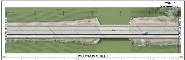
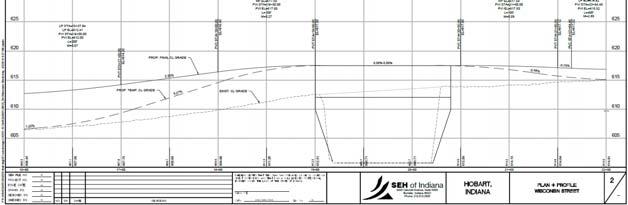
20 Bridge Modifications Wisconsin Street Crossing Lake George Frequently Closed due to Overtopping Critical Route to Hospital Bridge Modifications Wisconsin Street Crossing Lake George Road Overtopping Elevation = ft Peak Water Surface Elevations (FIS): 10-Year = ft (0.2 ft Water Depth) 50-Year = ft (4.1 ft Water Depth) 100-Year = ft (6.1 ft Water Depth) 500-Year = ft (11 ft Water Depth) September 2008 = ft (6.4 ft Water Depth) Bottom of Bridge Deck = ft 20


21 Bridge Modifications Wisconsin Street Crossing Lake George Bridge Modifications Wisconsin Street Crossing Lake George View from south side of Lake George during September 2008 event. Approximately 700 ft of road was inundated. 21

22 Bridge Modifications Wisconsin Street Crossing Lake George Due to overtopping, current crossing doesn t create significant flow restriction Inspection: Cracks & spalls on bridge deck, abutments, and pier Deteriorated fascia beam and pier cap Bridge Modifications Wisconsin Street Crossing Lake George Bridge Improvement Scenario 1: If profile is raised to reduce overtopping frequency and duration, bridge deck length will need to be increased. New road shoulder at elev ft (1 ft above 100-year headwater elev. of ft) Bridge span needs to be ~340 feet long to prevent upstream stage increases Current bridge span is 110 feet. 22
23 Bridge Modifications Wisconsin Street Crossing Lake George Bridge Improvement Scenario 2: If 3 rd Street is reconstructed first under separate project, bridge deck length could be reduced: New road shoulder at elev ft (1 ft above new 100-year headwater elevation of ft) Bridge span needs to be ~300 feet long to prevent upstream stage increases. Scenario 1 bridge span was ~340 feet. Current bridge span is 110 feet. Bridge Modifications Wisconsin Street Crossing Lake George Bridge Improvement Scenario 3: If 3 rd Street and Wisconsin Street are reconstructed under same project, Downstream BFE = (1.3 lower than effective) Upstream BFE = (1.1 lower than effective) New minimum road elev (at shoulder) Increase head differential across bridge without increasing regulatory BFEs. Bridge span could be reduced to ~140 feet. Scenario 2 bridge span was ~315 feet. Scenario 1 bridge span was ~340 feet. Current bridge span is 110 feet. 23

24 Bridge Modifications Summary of Scenarios: Lake Station Dam Lake Station Dam June USGS Gage Flow = 60 cfs. 24

25 Lake Station Dam Lake Station Dam July USGS Gage Flow = 1,400 cfs. Lake Station Dam 2 Flow Events Modeled: September 2008 Event August 2007 Event with Assumed Tailwater Condition Between 10-year & 50-year frequency 2 Alternatives Considered: Lake Station Dam Removed Lake Station Dam Replaced with Dam Capable of Drawing Down prior to Event 25


26 Lake Station Dam Lake Station Dam Removal NWL above dam reduced from to approx Pool area water surface narrows from ~235 feet to ~120 feet. Max decrease of 0.1 for Sept 2008 Event Max decrease of 3.9 for August 2007 Event with low tailwater condition No structures removed from inundation area due to narrow floodplain. Lake Station Dam 26

27 Lake Station Dam Lake Station Dam Replacement Pool NWL of (same as existing) Drawdown to Max decrease of 0.9 ft for August 2007 Event with low tailwater condition. No structures removed from inundation area due to narrow floodplain. No decrease shown for September 2008 Event. Existing Dam Seepage through sheet pile wall Sudden failure unlikely Bypass Tunnel 27

28 Bypass Tunnel Tunnel Length = 4,600 feet 2 Options Evaluated: Single 10-ft diameter tunnel Three parallel 10-ft diameter tunnels For September 2008 Event, maximum benefit of single tunnel is a decrease of 0.2 ft; 0.6 ft for triple tunnel. No structures are removed from inundation area. Floodplain Storage 3 Potential Storage Areas Evaluated 28
29 Floodplain Storage Rosser Storage: Area = 65 acres Rosser Lake NWL = 597 Adjacent County Park Lake NWL = Year Peak Elevation = 597 Drawdown Rosser Lake to match adjacent lake NWL prior to event. 600 ac-ft of storage gained for September 2008 Event (Less than 2% of Flood Volume of 36,000 ac-ft) No reduction in peak water surface elevations. Floodplain Storage Indiana Street/Arizona Street Storage: Area = 75 acres Significant Excavation Needed (more than 3 Million CY assumed for this analysis) 700 ac-ft of storage gained for September 2008 Event (Less than 2% of Flood Volume) No reduction in peak water surface elevations. 29
30 Floodplain Storage 37 th Avenue Storage: Area = 140 acres Significant Excavation Needed (more than 5 Million CY assumed for this analysis) 1,400 ac-ft of storage gained for September 2008 Event (4% of Flood Volume) Maximum reduction in peak water surface elevation for September 2008 Event is 0.1 ft. Floodplain Storage Storage Required to Make a Difference September 2008 Flood Volume = 36,000 ac-ft Storage Provided Upstream of Lake George 100-acre basin providing 1,000 ac-ft of storage results in decrease of 0.3 through Lake George 500-acre basin providing 4,000 ac-ft of storage results in decrease of 1.7 1,000-acre basin providing 6,000 ac-ft of storage results in decrease of


31 Lake George Dam Lake George Dam during Normal Stage Lake George Dam Lake George Dam during September 2008 Event 31
32 Lake George Dam Single 7 x 8 Drawdown Gate For Q = 200 cfs, Lake George could be drawn down 3 in 14 hours. If Lake is drawn down 3 prior to September 2008 event, 400 ac-ft of storage is added, peak elevations decrease by 0.1. Lake George Dam Other Considerations: 3 ft draw down results in average lake depth of 1.5 ft Lake bottom would be exposed in many areas Dredging could help maintain pool Retaining walls along Lake George could be damaged by draw down No advance warning system Court-established lake level of


33 Brickie Bowl Flooding Located along Duck Creek Brickie Bowl Flooding 33
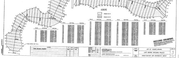
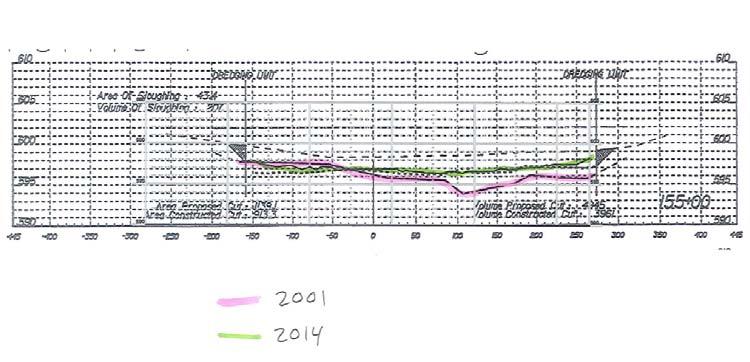
34 Brickie Bowl Flooding FIS profile of Duck Creek shows that Deep River controls peak elevations at Brickie Bowl for all events. Improving the railroad bridge could result in a peak water surface elevation decrease of 3.5 ft for the September 2008 event. September 2008 Peak WSE = ft 100-Year Peak WSE = ft Average field elevation = 603 ft Lake George Sedimentation Bathymetric survey compared to record drawings from 2000 dredging 70,000 CY has accumulated Stoke s Law confirms that fine particles can settle out in basin size of Lake George Prepared cross sections showing accumulation at several points throughout Lake George 34

35 Lake George Sedimentation Lake George Sedimentation 35

36 Lake George Sedimentation Lake George Sedimentation 36
37 Lake George Sedimentation Lake George Sedimentation 37
38 Lake George Sedimentation Lake George Sedimentation Permanent Sediment Management If the lake continues to act as a sediment trap, the decreasing pool area will reduce the sedimentation efficiency, sending more sediment downstream. May be able to restrict dredging activities to upstream of 3 rd Street Recreational & Ecological Impacts of Sedimentation Current average lake depth is 4-5 ft Upstream pools were not dredged in 2000, significant plant growth evident 38

39 Lake George Sedimentation Channel Conveyance Overbank clearing could reduce losses, lower peak water elevations. Heavy deciduous tree cover in overbank areas from CFE Railroad Bridge down to confluence with Little Calumet River If cleared trees in the overbanks, decrease peak water surface elevations by up to 0.8 for Sept 08 event 39

40 Channel Conveyance Channel narrows significantly at 37 th Avenue Bridge crossing. Eliminating restriction could lower peak water surface elevations by up to 0.3 Green Infrastructure EPA s Definition: Green infrastructure uses vegetation, soils, and natural processes to manage water and create healthier urban environments. At the scale of a city or county, green infrastructure refers to the patchwork of natural areas that provides habitat, flood protection, cleaner air and cleaner water. At the scale of a neighborhood or site, green infrastructure refers to stormwater management systems that mimic nature by soaking up and storing water. 40
41 Green Infrastructure Can be used in lieu of or together with traditional flood risk management solutions hydrograph indicates quick response of rainfall/runoff in watershed. If more runoff is detained upstream, can flatten out hydrograph and dampen peak flow. If implemented throughout watershed, benefits increase. Must be evaluated in detail to ensure green infrastructure does not cause adverse impact, especially in lower reaches of watershed. Property Acquisition/Structure Elevation Developing List of Properties within 100-yr Inundation Area Addresses & Values Legal/Administrative Process Options for Reducing Risk Acquire property & demolish Limited future use of property Rebuild elevated structure on property Detailed feasibility and cost analysis required Elevate existing structure on property Relocate existing structure 41
42 Other Considerations FEMA Hazard Mitigation Assistance Hazard Mitigation Grant Program For long-term hazard mitigation measures following a major disaster. Pre-Disaster Mitigation Program For hazard mitigation planning and projects on an annual basis Flood Mitigation Assistance Program For projects to reduce or eliminate risk of flood damage to buildings insured under NFIP on an annual basis. Model review by IDNR & FEMA Additional modeling of Burns Waterway & Little Calumet River needed. Project Prioritization Lake Station Approx. 230 structures inundated in Sept 08 Property Acquisition Levee Construction Property acquisition Interior drainage & pump station(s) Typical section: 42

43 Project Prioritization Hobart Sediment Management in Lake George 70,000 CY accumulated since 2000 Property Acquisition Snagging Fallen Trees CFE Railroad Bridge Improvements 3 rd Street & Wisconsin Street Improvements Assume they are permitted together 3 rd Street: Butler Fairman and Seufert, Inc. Wisconsin Street: Several considerations Project Prioritization Wisconsin Street 43
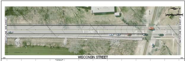
44 Project Prioritization Wisconsin Street Project Prioritization Wisconsin Street 44
45 Project Prioritization Wisconsin Street Project Prioritization CFE Railroad Bridge Feasibility Study 3.5 decrease for Sept 08 event Coordination with railroad is key Lake George Dredging Permanent dredging plan to maintain lake bathymetry and aesthetics Snagging/Clearing Debris Prevent damage to structures and blockages Additional Analysis Upstream & downstream 45
46 Project Prioritization Additional analysis Downstream: Tailwater Impacts Deep River FEMA FIS: Q 100 Burns Waterway = 4,640 cfs Q 100 Deep River = 5,500 cfs Effective model doesn t include confluence USACE model shows reverse flow of 1,000 cfs Important to have more detailed model of downstream area prior to pursuing Lake Station levee option Upstream: Evaluate impact of future development and benefits of implementing Green Infrastructure Next Steps City of Hobart June 3 Letter Requesting assistance with the following: Reconstruction of Wisconsin Street & Bridge and 3 rd Street Bridge Permit together with Wisconsin Street to reduce overall construction costs. Construction Sequence:» Wisconsin Street Bridge first» 3 rd Street Bridge second» Wisconsin Street Causeway third Scoping Report for CFE Railroad Bridge Lake George Dredging 46
IAFSM 2010 Annual Conference. City of Rockford Keith Creek Greenway Flood Mitigation Project
 IAFSM 2010 Annual Conference City of Rockford Keith Creek Greenway Flood Mitigation Project March 10, 2010 Introduction Problem Overview 1890 s Building of homes along Keith Creek 1920 s Home construction
June 22, Francis E. Borcalli, P.E.
 CACHE CREEK SETTLING BASIN SYMPOSIUM Managing the Settling Basin Who s Doing What! June 22, 2009 Francis E. Borcalli, P.E. CACHE CREEK SETTLING BASIN SYMPOSIUM Managing the Settling Basin Who s Doing What!
City of Katy Flood Protection Study (Meeting 3 of 3) October 23, 2017
 October 23, 2017") City of Katy Flood Protection Study (Meeting 3 of 3) October 23, 2017 Phasing of Meetings April Meeting May Meeting October Review of Tax Day Storm Event and Immediate Actions Taken By City Review of Coordination
City of Katy Flood Protection Study (Meeting 3 of 3) October 23, 2017 Phasing of Meetings April Meeting May Meeting October Review of Tax Day Storm Event and Immediate Actions Taken By City Review of Coordination
INFLOW DESIGN FLOOD CONTROL SYSTEM PLAN 40 C.F.R. PART PLANT YATES ASH POND 3 (AP-3) GEORGIA POWER COMPANY
 GEORGIA POWER COMPANY") INFLOW DESIGN FLOOD CONTROL SYSTEM PLAN 40 C.F.R. PART 257.82 PLANT YATES ASH POND 3 (AP-3) GEORGIA POWER COMPANY EPA s Disposal of Coal Combustion Residuals from Electric Utilities Final Rule (40 C.F.R.
INFLOW DESIGN FLOOD CONTROL SYSTEM PLAN 40 C.F.R. PART 257.82 PLANT YATES ASH POND 3 (AP-3) GEORGIA POWER COMPANY EPA s Disposal of Coal Combustion Residuals from Electric Utilities Final Rule (40 C.F.R.
CHAPTER 7. San Dieguito River Flooding Adaptation
 CHAPTER 7 San Dieguito River Flooding Adaptation This chapter includes a range of adaptation measures to address vulnerabilities from flooding along the San Dieguito River, including the river valley,
Hydrologic Calibration:
 Hydrologic Calibration: UPDATE OF EFFECTIVE HYDROLOGY FOR MARYS CREEK October 2010 Agenda Background Hydrologic model Calibrated rainfall Hydrologic calibration 100 year discharges, Existing Conditions
INFLOW DESIGN FLOOD CONTROL SYSTEM PLAN 40 C.F.R. PART PLANT BOWEN ASH POND 1 (AP-1) GEORGIA POWER COMPANY
 GEORGIA POWER COMPANY") INFLOW DESIGN FLOOD CONTROL SYSTEM PLAN 40 C.F.R. PART 257.82 PLANT BOWEN ASH POND 1 (AP-1) GEORGIA POWER COMPANY EPA s Disposal of Coal Combustion Residuals from Electric Utilities Final Rule (40 C.F.R.
INFLOW DESIGN FLOOD CONTROL SYSTEM PLAN 40 C.F.R. PART 257.82 PLANT BOWEN ASH POND 1 (AP-1) GEORGIA POWER COMPANY EPA s Disposal of Coal Combustion Residuals from Electric Utilities Final Rule (40 C.F.R.
SECTION 11: REGULATORY FLOODWAYS
 SECTION 11: REGULATORY FLOODWAYS Contents 11.1. The Floodway... 11-2 11.1.1. The floodway concept... 11-2 11.1.2. Floodway map... 11-2 11.1.3. Floodway permitting... 11-3 11.1.4. Changing the floodway...
PRESENTERS. Contact Information: RW Armstrong Union Station, 300 S. Meridian St. Indianapolis, IN
 1 PRESENTERS David Bourff, Director of Environmental Planning Simon Davies, LEED AP, Environmental Scientist Summer O Brien, PWS, Senior Environmental Scientist Contact Information: RW Armstrong Union
Lower San Joaquin River Feasibility Study PLAN FORMULATION ADDENDUM
 PLAN FORMULATION ADDENDUM Non-Structural Measure Descriptions Elevate Critical Infrastructure This measure would raise at-risk critical structures above the design inundation level. Elevation would be
INFLOW DESIGN FLOOD CONTROL SYSTEM PLAN 40 C.F.R. PART PLANT YATES ASH POND B (AP-B ) GEORGIA POWER COMPANY
 GEORGIA POWER COMPANY") INFLOW DESIGN FLOOD CONTROL SYSTEM PLAN 40 C.F.R. PART 257.82 PLANT YATES ASH POND B (AP-B ) GEORGIA POWER COMPANY EPA s Disposal of Coal Combustion Residuals from Electric Utilities Final Rule (40 C.F.R.
INFLOW DESIGN FLOOD CONTROL SYSTEM PLAN 40 C.F.R. PART 257.82 PLANT YATES ASH POND B (AP-B ) GEORGIA POWER COMPANY EPA s Disposal of Coal Combustion Residuals from Electric Utilities Final Rule (40 C.F.R.
Freight Street Development Strategy
 Freight Street Development Strategy Appendix B: Naugatuck River Floodplain Analysis Freight Street Development Strategy DECEMBER 2017 Page B-1 1.0 NAUGATUCK RIVER FLOODPLAIN AT FREIGHT STREET 1.1 Watershed
Modeling a Complex Hydraulic Environment Using a 1-D Approach Supplemented with Simple 2-D Principles Manas Borah Ed Dickson June 5, 2014
 ASFPM 2014 Annual Conference Modeling a Complex Hydraulic Environment Using a 1-D Approach Supplemented with Simple 2-D Principles Manas Borah Ed Dickson June 5, 2014 Agenda Overview and Background Hydrology
ND Detention Project Development Update
 ND Detention Project Development Update Upper Red River Basin Halstad, MN = 8 Upstream Subwatersheds Fargo, ND = 3 Upstream Subwatersheds Halstad, MN Fargo, ND Wild Rice Otter Tail Bois de Sioux Upstream
Appendix J Hydrology and Hydraulics
 Appendix J Hydrology and Hydraulics Marsh Lake Dam Ecosystems Restoration Feasibility Study Hydraulics & Hydrology Appendix January 2011 Contents List of Figures iii List of Tables iii I. General 1 II.
5th Street Bridge Replacement Project Yuba City, California Location Hydraulic Study Report Bridge No. 18C0012
 EA 03-0L2324 Yuba City, California Location Hydraulic Study Report Submitted to: Prepared by: November 2012 Table of Contents Executive Summary... iii Acronyms... v 1 General Description... 1 1.1 Project
New Castle County, DE. Floodplain Regulations
 New Castle County, DE Floodplain Regulations John J. Gysling, PE CFM Department of Land Use New Castle County, DE February 26, 2009 Today s Presentation Floodplain Protection and Uses Terms and Definitions
Local Flood Hazard Mitigation Program. A framework for hazard mitigation in the NYC West of Hudson Water Supply Watersheds
 Local Flood Hazard Mitigation Program A framework for hazard mitigation in the NYC West of Hudson Water Supply Watersheds Flood Hazard Mitigation Defined 2 2 Presentation Overview Why and how is the NYC
PRESENTATION FOR THE POTENTIAL ADDITION OF SPECIAL FLOOD HAZARD AREAS
 PRESENTATION FOR THE POTENTIAL ADDITION OF SPECIAL FLOOD HAZARD AREAS 1 255 255 255 237 237 237 217 217 217 200 200 200 Part 1: Summary of Floodplain Analysis for Los 0 Angeles 163 131 River239 110 112
INFLOW DESIGN FLOOD CONTROL SYSTEM PLAN PLANT BARRY ASH POND ALABAMA POWER COMPANY
 INFLOW DESIGN FLOOD CONTROL SYSTEM PLAN PLANT BARRY ASH POND ALABAMA POWER COMPANY Section 257.82 of EPA s regulations requires the owner or operator of an existing or new CCR surface impoundment or any
Chapter 11 Culverts and Bridges
 Chapter 11 Culverts and Bridges Contents 1.0 Introduction... 1 2.0 General Design... 1 2.1 Design Criteria... 1 2.2 Design Flows... 1 2.3 Permitting and Regulations... 1 2.4 Aesthetics and Safety... 2
Project Drainage Report
 Design Manual Chapter 2 - Stormwater 2A - General Information 2A-4 Project Drainage Report A. Purpose The purpose of the project drainage report is to identify and propose specific solutions to stormwater
Lyon Creek Cedar Way Stormwater Detention Dam Operation and Maintenance Manual
 Lyon Creek Cedar Way Stormwater Detention Dam Operation and Maintenance Manual Prepared by: Mike Shaw Stormwater Program Manager City of Mountlake Terrace January 2010 Section I General Information This
COON CREEK WATERSHED DISTRICT PERMIT REVIEW. Spring Lake Park Schools Westwood Middle School st Avenue NE, Spring Lake Park, MN 55432
 PAN 16-112, Westwood Middle School, Page 1 of 6 COON CREEK WATERSHED DISTRICT PERMIT REVIEW MEETING DATE: August 22, 2016 AGENDA NUMBER: 10 FILE NUMBER: 16-112 ITEM: Westwood Middle School RECOMMENDATION:
DRAFT. Jacob Torres, P.E.; Nick Fang, Ph.D., P.E.
 \ Memorandum SSPEED Center at Rice University Department of Civil & Environmental Engineering 6100 Main MS-317 Houston, Texas 77005-1827 sspeed.rice.edu tel: 713-348-4977 To Andy Yung, P.E. CFM; Lane Lease,
PAPERWORK REDUCTION ACT A. GENERAL
 U.S. DEPARTMENT OF HOMELAND SECURITY - FEDERAL EMERGENCY MANAGEMENT AGENCY RIVERINE STRUCTURES FORM O.M.B No. 1660-0016 Expires: 12/31/2010 PAPERWORK REDUCTION ACT Public reporting burden for this form
Appendix G Preliminary Hydrology Study
 Appendix G Preliminary Hydrology Study Preliminary Hydrology Study VESTING TTM 72608 Long Beach, CA Prepared for: The Long Beach Project, LLC 888 San Clemente, Suite 100 New Port Beach, CA May 28, 2014
Appendix VI: Illustrative example
 Central Valley Hydrology Study (CVHS) Appendix VI: Illustrative example November 5, 2009 US Army Corps of Engineers, Sacramento District Prepared by: David Ford Consulting Engineers, Inc. Table of contents
EFFECT OF UPSTREAM DEVELOPMENT ON THE CLEAR CREEK AREA
 EFFECT OF UPSTREAM DEVELOPMENT ON THE CLEAR CREEK AREA Technical Memorandum Farming in the Floodplain Project Prepared for May 2017 PCC Farmland Trust Photo credit: Google Earth TABLE OF CONTENTS Page
PRINCESS ANNE DISTRICT STORMWATER PROJECTS
 PRINCESS ANNE DISTRICT STORMWATER PROJECTS Topics o o o o o Sea Level Rise and the Southern Watersheds Ashville Park Sherwood Lakes Kingston Estates Drainage Operations & Maintenance in the Southern Watersheds
V. DRAINAGE IMPROVEMENTS
 V. DRAINAGE IMPROVEMENTS 5.1 Formulation of Drainage Improvements As indicated in Chapter 4, following the completion of the hydrologic analysis associated with future land use conditions, drainage improvements
Chehalis Basin Strategy Programmatic SEPA Draft EIS
 Chehalis Basin Strategy Programmatic SEPA Draft EIS History of Flooding I-5 closed in 1990, 1996, 2007, 2009 Five largest flood events occurred since 1986 2 History of Habitat Degradation Harvest has been
A Study to Estimate Current and Future CSOs to Bubbly Creek and Identify Impacts on the Chicago Area Waterways (CAWS)
") A Study to Estimate Current and Future CSOs to Bubbly Creek and Identify Impacts on the Chicago Area Waterways (CAWS) IWEA WATERCON 2012 Springfield, Illinois March 19, 2012 presented by David Kiel, USACE
A Study to Estimate Current and Future CSOs to Bubbly Creek and Identify Impacts on the Chicago Area Waterways (CAWS) IWEA WATERCON 2012 Springfield, Illinois March 19, 2012 presented by David Kiel, USACE
III. INVENTORY OF EXISTING FACILITIES
 III. INVENTORY OF EXISTING FACILITIES Within the Growth Management Boundary, the existing storm drainage facilities are largely associated with development that has historically occurred in the ten drainage
FIRM NAME DESIGNER: CHECKER: DATE: FPID #: DESCRIPTION: COUNTY: DRAINAGE DESIGN CHECKLIST. Designers Initials. Checkers Initials.
 I. Drainage Report A. Executive Summary - Brief Overview of Project Drainage Design B. Project Description 1. Existing Conditions 2. Proposed Project Conditions 3. Project Justification Narrative - Basin
SECTION 7.0 PROJECT FEASIBILITY, ENGINEER S RECOMMENDATION AND DESIGN ISSUES NEEDING RESOLUTION
 SECTION 7.0 PROJECT FEASIBILITY, ENGINEER S RECOMMENDATION AND DESIGN ISSUES NEEDING RESOLUTION 7.1 PROJECT FEASIBILITY The determination of project feasibility is based upon several criteria established
INFLOW DESIGN FLOOD CONTROL SYSTEM PLAN 40 C.F.R. PART PLANT DANIEL ASH POND B MISSISSIPPI POWER COMPANY
 INFLOW DESIGN FLOOD CONTROL SYSTEM PLAN 40 C.F.R. PART 257.82 PLANT DANIEL ASH POND B MISSISSIPPI POWER COMPANY EPA s Disposal of Coal Combustion Residuals from Electric Utilities Final Rule (40 C.F.R.
Informational Meeting- July 21, Boxelder B-2/B-3 Watershed Planning Study
 Informational Meeting- July 21, 2015 Boxelder B-2/B-3 Watershed Planning Study Agenda Introductions Background & History Purpose & Need NRCS Watershed Planning Program Work Completed to Date Longer term
Ponds. Pond A water impoundment made by excavating a pit, or constructing a dam or an embankment.
 POND SITE SELECTION AND CONSTRUCTION Uses, Planning, & Design David Krietemeyer Area Engineer USDA-NRCS June 20, 2008 Uses Considerations for Location of Commonly Used Terms Pond A water impoundment made
E. STORMWATER MANAGEMENT
 E. STORMWATER MANAGEMENT 1. Existing Conditions The Project Site is located within the Lower Hudson Watershed. According to the New York State Department of Environmental Conservation (NYSDEC), Lower Hudson
Phase II Report on Hydrology, Hydraulics, and Low Water Dams
 Phase II Report on Hydrology, Hydraulics, and Low Water Dams Arkansas River Corridor Tulsa, OK May 2005 Submitted To: U. S. Army Corps of Engineers Tulsa District Prepared by: The GUERNSEY Team 5555 N.
Informational Meeting- March 31, Boxelder B-2/B-3 Watershed Planning Study
 Informational Meeting- March 31, 2016 Boxelder B-2/B-3 Watershed Planning Study Agenda Introductions Work Completed to Date Phase 1 Evaluations Alternatives Evaluations Economic Evaluations Draft Watershed
Temporary Watercourse Crossing: Culverts
 Temporary Watercourse Crossing: Culverts DRAINAGE CONTROL TECHNIQUE Low Gradient Velocity Control Short Term Steep Gradient Channel Lining Medium-Long Term Outlet Control Soil Treatment Permanent Symbol
Table D-1. Montour County Hazard Mitigation Projects - Municipalities Affected. Structural Projects
 Table D-1 Montour County Hazard Mitigation Projects - Municipalities Affected Structural Projects Project Description Mitigation Objective Hazard Municipality(s) Affected Pursue re-mapping of the 100-year
Location Drainage Study
 Location Drainage Study PROJECT ROUTE: LIMITS: MUNICIPALITY/COUNTY: JOB NUMBER: IL 47 at Burlington Road 750ft NW to 750ft SE of IL 47(Burlington), & 1000ft S to 1000ft N of Burlington (IL47) Kane County
LOWER CACHE CREEK, YOLO COUNTY WOODLAND AREA FEASIBILITY STUDY
 Background LOWER CACHE CREEK, YOLO COUNTY WOODLAND AREA FEASIBILITY STUDY Energy and Water Development Appropriations Act of 1993 Reconnaissance Study completed June 1994 Feasibility Cost Share Agreement
U.S. Army Corps of Engineers Permit Application Tips
 U.S. Army Corps of Engineers Permit Application Tips MnDOT Environmental Conference Ben Orne and Sarah Wingert, USACE 4-29-2015 US Army Corps of Engineers BUILDING STRONG Outline Introduction to Corps
ASHVILLE PARK STORMWATER UPDATE
 ASHVILLE PARK STORMWATER UPDATE JULY 18, 2017 1 ASHVILLE PARK CHRONOLOGY 2005: Ashville Park conditionally rezoned. Consisted of Five Villages 2006-2007: Village A Wilshire Village was approved and construction
HYDROLOGIC-HYDRAULIC STUDY ISABELLA OCEAN RESIDENCES ISLA VERDE, CAROLINA, PR
 HYDROLOGIC-HYDRAULIC STUDY ISABELLA OCEAN RESIDENCES ISLA VERDE, CAROLINA, PR 1 INTRODUCTION 1.1 Project Description and Location Isabella Ocean Residences is a residential development to be constructed
Fargo-Moorhead Metropolitan Area Flood Risk Management Project
 Fargo-Moorhead Metropolitan Area Flood Risk Management Project 52ND ANNUAL IOWA ASCE ENVIRONMENTAL & WATER RESOURCES CONFERENCE 03 April 2014 Aaron W. Buesing Senior Hydraulic Engineer Corps of Engineers,
HEC-RAS 2D Modeling in Support of Ascension Parish Levee Certification
 HEC-RAS 2D Modeling in Support of Ascension Parish Levee Certification OFMA 2017 Annual Conference September 19, 2017 Presented by: Jeff Doudrick, PE, ENV SP Project Manager HNTB Corporation Agenda Project
APPENDIX A HYDROLOGIC AND HYDRAULIC ANALYSIS
 APPENDIX A HYDROLOGIC AND HYDRAULIC ANALYSIS GENERAL The Hydrologic and Hydraulic information presented in this appendix is provided as a supplement to the Dallas Floodway Extension General Re-evaluation
Hydrology and Flooding
 Hydrology and Flooding Background The 1996 flood Between February 4, 1996 and February 9, 1996 the Nehalem reporting station received 28.9 inches of rain. Approximately 14 inches fell in one 48 hour period.
Upper Des Plaines River Feasibility Study. Appendix A Hydrology and Hydraulics
 Upper Des Plaines River Feasibility Study Appendix A Hydrology and Hydraulics August 2013 (DRAFT) Study Partnership Illinois Department of Natural Resources (IDNR) Southeastern Wisconsin Regional Planning
Fullerton Creek Channel (OCFCD Facility No. A03) from downstream Beach Blvd. including undercrossing to downstream I-5 Freeway.
 from downstream Beach Blvd. including undercrossing to downstream I-5 Freeway.") Fullerton Creek Channel (OCFCD Facility. A03) Lead Agency: Agency: Project Director: Address: Orange County, Public Works, Infrastructure Programs, Capital Programs Sam Ali 300 N. Flower Street Santa Ana
Fullerton Creek Channel (OCFCD Facility. A03) Lead Agency: Agency: Project Director: Address: Orange County, Public Works, Infrastructure Programs, Capital Programs Sam Ali 300 N. Flower Street Santa Ana
DESIGN BULLETIN #16/2003 (Revised July 2007) Drainage Guidelines for Highways Under Provincial Jurisdiction in Urban Areas.
 Drainage Guidelines for Highways Under Provincial Jurisdiction in Urban Areas.") Drainage Guidelines for Highways Under Provincial Jurisdiction in Urban Areas. July 2007 Update to Design Bulletin #16/2003: Added under Design Criteria Culverts of 600mm diameter are commonly used to
Drainage Guidelines for Highways Under Provincial Jurisdiction in Urban Areas. July 2007 Update to Design Bulletin #16/2003: Added under Design Criteria Culverts of 600mm diameter are commonly used to
Environmental Protection (NJDEP) The Louis Berger Group, Inc.
 The Louis Berger Group, Inc.") Hydraulic Modeling for Preliminary Evaluation of Potential Flooding Impacts for Various Dredging, Capping and Armoring Scenarios of The Lower Passaic River Restoration Abdulai Fofanah, PE, D.WRE, CFM Murat
Hydraulic Modeling for Preliminary Evaluation of Potential Flooding Impacts for Various Dredging, Capping and Armoring Scenarios of The Lower Passaic River Restoration Abdulai Fofanah, PE, D.WRE, CFM Murat
STREAM RESTORATION PURPOSE, PRACTICE, AND METHODS. By Marcus Rubenstein, CPESC
 STREAM RESTORATION PURPOSE, PRACTICE, AND METHODS By Marcus Rubenstein, CPESC WHAT IS STREAM RESTORATION? The return of a stream s lost natural functions, usually resulting from watershed alterations,
Lessons [being] learnt 2016 Flood in Cedar Rapids. Sandy Pumphrey Project Engineer II Flood Mitigation
![Lessons [being] learnt 2016 Flood in Cedar Rapids. Sandy Pumphrey Project Engineer II Flood Mitigation](/thumbs/77/74998790.jpg "Lessons [being] learnt 2016 Flood in Cedar Rapids. Sandy Pumphrey Project Engineer II Flood Mitigation") Lessons [being] learnt 2016 Flood in Cedar Rapids Sandy Pumphrey Project Engineer II Flood Mitigation 319 286 5363 s.pumphrey@cedar-rapids.org Agenda 2008 Flood Event 2016 Flood Event [Long Term] Flood
Lessons [being] learnt 2016 Flood in Cedar Rapids Sandy Pumphrey Project Engineer II Flood Mitigation 319 286 5363 s.pumphrey@cedar-rapids.org Agenda 2008 Flood Event 2016 Flood Event [Long Term] Flood
S.R. 4031, SECTION FVR OVER BEAVER RUN SEGMENT 0170, OFFSET 6093 EAST NANTMEAL TOWNSHIP, CHESTER CO. ENGINEERING DISTRICT 6-0
 S.R. 4031, SECTION FVR OVER BEAVER RUN SEGMENT 0170, OFFSET 6093 EAST NANTMEAL TOWNSHIP, CHESTER CO. ENGINEERING DISTRICT 6-0 HYDROLOGIC & HYDRAULIC STUDY REPORT OCTOBER 2007 Prepared For: Prepared By:
Outlet Structure Modeling
 Watershed Modeling using HEC-RAS Outlet Structure Modeling Jeff Wickenkamp, P.E., CFM, D.WRE Patrick Lach, P.E. Hey and Associates, Inc. Water Resources, Wetlands and Ecology Outline of Presentation Why
FY16 RSM IPR Portland District, Optimizing Fall Creek Reservoir Flush TMDL s, Stanford Gibson, Chris Nygaard, Jim Crain, Jarod Norton
 Fall Creek Reservoir Fall Creek Dam is at river mile 7.2 on Fall Creek, a tributary of the Willamette River, about 20 miles southeast of Eugene, OR. Dam works in coordination with Lookout Point and Hills
ENVIRONMENTAL RESOURCE PERMIT APPLICATION
 ENVIRONMENTAL RESOURCE PERMIT APPLICATION SOUTHWEST FLORIDA WATER MANAGEMENT DISTRICT 2379 BROAD STREET, BROOKSVILLE, FL 34604-6899 (352) 796-7211 OR FLORIDA WATS 1 (800) 423-1476 SECTION E INFORMATION
Suspended Sediment Discharges in Streams
 US Army Corps of Engineers Hydrologic Engineering Center Suspended Sediment Discharges in Streams April 1969 Approved for Public Release. Distribution Unlimited. TP-19 REPORT DOCUMENTATION PAGE Form Approved
King County Flood Control District approves grants for flood prevention projects Regional projects to benefit from district funds
 News Release Contact: Al Sanders 206-477-1016 August 31, 2015 Flood Control District approves grants for flood prevention projects Regional projects to benefit from district funds The Flood Control District
THE CROSSROADS IN WINCHESTER 4. DRAINAGE PLAN. 4. Drainage Plan. a. Drainage Plan Description
 THE CROSSROADS IN WINCHESTER 4. DRAINAGE PLAN 4. Drainage Plan a. Drainage Plan Description The Specific Plan area drains naturally into two separate watersheds: approximately 6 percent of the Specific
Supplemental Watershed Plan Agreement No. 10 for Neshaminy Creek Watershed Core Creek Dam (PA-620) Bucks County, Pennsylvania
 Bucks County, Pennsylvania") Supplemental Watershed Plan Agreement No. 10 for Neshaminy Creek Watershed Core Creek Dam (PA-620) Bucks County, Pennsylvania Project Authorization USDA's Small Watershed Program is carried out under the
Supplemental Watershed Plan Agreement No. 10 for Neshaminy Creek Watershed Core Creek Dam (PA-620) Bucks County, Pennsylvania Project Authorization USDA's Small Watershed Program is carried out under the
NOTICE OF PREPARATION
 NOTICE OF PREPARATION Date: June 12, 2014 To: From: Subject: Governor s Office of Planning and Research/State Clearinghouse Unit, Responsible Agencies, Trustee Agencies, and Interested Parties Announcement
Inflow Design Flood Control System Plan for Louisa Generating Station CCR Impoundment. MidAmerican Energy Company
 Control System Plan for Louisa Generating Station CCR Impoundment MidAmerican Energy Company October 10, 2016 Control System Plan for Louisa Generating Station CCR Impoundment Prepared for MidAmerican
MODEL Stormwater Local Design Manual. City of Centerville
 MODEL Stormwater Local Design Manual City of Centerville Adopted December 6, 2005 TABLE OF CONTENTS 1. FORWARD... 1 2. GENERAL LEVEL OF SERVICE STANDARDS... 1 2.1. DETENTION REQUIREMENTS... 1 2.1.1. Discharge
COUNTY OF KANE. Kishwaukee River Headwaters Study Stakeholder Meeting Monday, February 26, :30 am Hampshire Village Hall
 COUNTY OF KANE ENVIRONMENTAL AND BUILDING MANAGEMENT Timothy Harbaugh, P.E., DEE Director County Government Center 719 Batavia Avenue Geneva, IL 60134 www.co.kane.il.us Environmental Management: (630)
PARR HYDROELECTRIC PROJECT PARR HYDRO DEVELOPMENT & FAIRFIELD PUMPED STORAGE FACILITY DEVELOPMENT FERC PROJECT No SC SEPTEMBER 19, 2012
 PARR HYDROELECTRIC PROJECT PARR HYDRO DEVELOPMENT & FAIRFIELD PUMPED STORAGE FACILITY DEVELOPMENT FERC PROJECT No. 1894 - SC SEPTEMBER 19, 2012 PARR AND FAIRFIELD LOCATIONS Lockhart Neal Shoals Monticello
Alternative Approaches to Water Resource System Simulation
 US Army Corps of Engineers Hydrologic Engineering Center Alternative Approaches to Water Resource System Simulation May 1972 Approved for Public Release. Distribution Unlimited. TP-32 REPORT DOCUMENTATION
Kane County Natural Hazards Mitigation Committee
 Kane County Natural Hazards Mitigation Committee Annual Report For 2004 TO: Members of the Kane County Board FROM: Kane County Natural Hazards Mitigation Committee SUBJECT: Annual Report for 2004 Date:
PRELIMINARY DRAINAGE REPORT NEWCASTLE FIRE STATION OLD STATE HIGHWAY
 PRELIMINARY DRAINAGE REPORT FOR THE NEWCASTLE FIRE STATION OLD STATE HIGHWAY PREPARED FOR THE NEWCASTLE FIRE PROTECTION DISTRICT JULY 2014 BY ROSEVILLE DESIGN GROUP, INC. ROSEVILLE DESIGN GROUP, Inc Established
UPRR criteria for sizing waterway openings under bridges and through culverts are as follows:
 UNION PACIFIC RAILROAD SCOPE OF HYDROLOGIC/HYDRAULIC DESIGN ENGINEERING AND PERMITTING SERVICES FOR SIZING WATERWAY OPENINGS AT NEW AND REPLACEMENT STRICTURES These flood passage criteria were developed
HYDROLOGY REPORT HEACOCK & CACTUS CHANNELS MORENO VALLEY, CALIFORNIA NOVEMBER 2005 REVISED APRIL 2006 REVISED AUGUST 2006
 HYDROLOGY REPORT HEACOCK & CACTUS CHANNELS MORENO VALLEY, CALIFORNIA NOVEMBER 2005 REVISED APRIL 2006 REVISED AUGUST 2006 RIVERSIDE COUNTY FLOOD CONTROL AND WATER CONSERVATION DISTRICT TABLE OF CONTENTS
Stormwater Local Design Manual For Houston County, Georgia
 Stormwater Local Design Manual For Houston County, Georgia Adopted November 15, 2005 TABLE OF CONTENTS 1. FORWARD... 1 2. GENERAL LEVEL OF SERVICE STANDARDS... 2 2.1. DETENTION REQUIREMENTS... 2 2.1.1.
Base Level Engineering Elizabeth Savage, RPML, H2O Partners Diane Howe, FEMA Region 6. May 4, 2017
 Base Level Engineering Elizabeth Savage, RPML, H2O Partners Diane Howe, FEMA Region 6 May 4, 2017 What is Base Level Engineering Measuring stick to allow FEMA to assess its current flood maps. Cursory
Outcomes. Kelly Karll-SEMCOG Margaret Barondess - MDOT
 Eco-Logical: I-75 Corridor I-75 Conservation Transportation Action Planning in to Monroe Achieve County: Multiple Stormwater Environmental Considerations Outcomes Kelly Karll-SEMCOG Karll@semcog.org Margaret
 ASHVILLE PARK STORMWATER UPDATE JULY 18, 2017 1 ASHVILLE PARK CHRONOLOGY 2005: Ashville Park conditionally rezoned. Consisted of Five Villages 2006-2007: Village A Wilshire Village was approved and construction
Summary of Detention Pond Calculation Canyon Estates American Canyon, California
 July 15, 2015 Bellecci & Associates, Inc Summary of Detention Pond Calculation Canyon Estates American Canyon, California 1. Methodology: Method: Unit Hydrograph Software: Bentley Pond Pack Version 8i
FINDINGS: Olsson used a three-step analysis strategy to develop a benefit cost ratio that would indicate the relative feasibility of this project.
 EXECUTIVE SUMMARY FINDINGS: Based on the results of this feasibility study, the Platte Republican Diversion Project would be cost-effective. With minimal improvements to the channel, and the existing bridge
RIPARIAN CORRIDOR STUDY FINAL CITY CREEK MANAGEMENT PLAN TABLE OF CONTENTS
 TABLE OF CONTENTS 1.0 INTRODUCTION... 1-1 Riparian Corridor Study and Management Plan Goals... 1-1 Study Area... 1-2 Importance and Functions of Riparian Corridors... 1-2 Habitat for Mammals, Birds, and
Climate Change Impacts on Joint Riverine and Coastal Flooding on Calleguas Creek in Ventura County, CA
 Climate Change Impacts on Joint Riverine and Coastal Flooding on Calleguas Creek in Ventura County, CA James Gregory, James Jackson (ESA) Lily Verdone (TNC) FMA, September 8, 2016 Project Overview Coastal
Hypothetical Flood Computation for a Stream System
 US Army Corps of Engineers Hydrologic Engineering Center Hypothetical Flood Computation for a Stream System December 1968 Approved for Public Release. Distribution Unlimited. TP-12 REPORT DOCUMENTATION
2A Stormwater Regulations and Permitting A. Iowa Drainage Law and Resources 1 B. Regulated Activities 1
 Design Manual Chapter 2 - Stormwater Table of Contents TOC Table of Contents Chapter 2 - Stormwater 2A General Information 2A-1--------------------------------General Information A. Concept... 1 B. Informing
Good morning, Chairman Yaw, Chairman Yudichak, Chairman Vulakovich, Chairman Costa,
 Testimony of Patrick McDonnell, Secretary Pennsylvania Department of Environmental Protection Joint Hearing on Flooding and Emergency Response Senate Environmental Resources & Energy and Veterans Affairs
SAN BRUNO CREEK / COLMA CREEK RESILIENCY STUDY FINAL REPORT
 SAN BRUNO CREEK / COLMA CREEK RESILIENCY STUDY FINAL REPORT Prepared for: San Francisco International Airport RFP: 8354.1 Prepared by: August 2015 M&N Job No: 7981 Final Report Page E-1 EXECUTIVE SUMMARY
DALLAS FLOODWAY PROJECT
 DALLAS FLOODWAY PROJECT DRAFT FEASIBILITY REPORT and DRAFT ENVIRONMENTAL IMPACT STATEMENT PUBLIC MEETING Rob Newman Director, Trinity River Corridor Project, Fort Worth District 8 May 2014 US Army Corps
CHAPTER 9 DISCUSSIONS, CONCLUSIONS, AND RECOMMENDATIONS
 CHAPTER 9 DISCUSSIONS, CONCLUSIONS, AND RECOMMENDATIONS This chapter summarizes the results of feasibility level investigations undertaken to identify solutions to the water and related land resource problems
Gwinnett County Stormwater System Assessment Program
 Gwinnett County Stormwater System Assessment Program Jonathan Semerjian, PE Dept. of Water Resources Stormwater Management Sam Fleming, PE Dewberry Presentation Overview Project Background Drivers Enhanced
Coal Combustion Facility Assessment Report. October 20, 2010
 Coal Combustion Facility Assessment Report October 20, 2010 Introduction Stantec Consulting Services Inc. North American Consulting Firm 10,000 Engineers, Geologists, Architects, Scientists and Technicians
Bexar County Flood Warning System. Curtis Beitel, PE, CFM, Anthony Henry and Wayne Tschirhart, PE, PMP
 Bexar County Flood Warning System Curtis Beitel, PE, CFM, Anthony Henry and Wayne Tschirhart, PE, PMP Software Overview 2 Processes Hydrometric DB Event Manager Automatic Low = Every 6 hours High = Every
Project Alignment Appendix A
 Project Alignment Appendix A Fargo Moorhead Metropolitan Area Flood Risk Management Project EA Document This page is intentionally left blank Project Alignment Appendix A Table of Contents 1 BACKGROUND...
Fort Leonard Wood, Missouri. September 2013
 Fort Leonard Wood, Missouri September 2013 1 Presenters Shannon Kelly, Physical Scientist Clean Water Act Program Manager Directorate of Public Works Environmental Division Environmental Compliance Branch
Appendix G: Hydrology-Related Reports
 Appendix G: Hydrology-Related Reports (Hydraulic Summary of the Proposed Hawk Street Bridge, Bay Area Hydrology Model Project Report, Preliminary Stormwater Treatment Plan and Details, Evaluation of Potential
Chapter 6 DOCUMENTATION OF HYDRAULIC STUDIES SOUTH DAKOTA DRAINAGE MANUAL
 Chapter 6 DOCUMENTATION OF HYDRAULIC STUDIES SOUTH DAKOTA DRAINAGE MANUAL October 2011 Table of Contents Section Page 6.1 INTRODUCTION...6-1 6.1.1 General...6-1 6.1.2 Purpose...6-1 6.1.3 Objectives...6-2