FROZEN MEET AND GREET AT EPCOT NORWAY PAVILION STORMWATER CALCULATIONS FOR
|
|
|
- Brett Shelton
- 6 years ago
- Views:
Transcription
1 FROZEN MEET AND GREET AT EPCOT NORWAY PAVILION STORMWATER CALCULATIONS FOR SOUTH FLORIDA WATER MANAGEMENT DISTRICT AND REEDY CREEK IMPROVEMENT DISTRICT Prepared by: Heery International, Inc Millenia Blvd. Suite 550 Orlando, FL EB Project No December 3, 2014 REVISED December 23, 2014 REVISED January 5, 2015
2 Table of Contents Section 1.0 Section 2.0 Section 3.0 Section 4.0 Section 5.0 Section 6.0 Section 7.0 Section 8.0 Section 9.0 Overview Application Type Location Figure 1 Location Map Figure 2 Aerial Photograph Figure 3 Aerial Photograph Figure 4 Soils Map Project Site Description Proposed Project Land Use Existing Conditions Description Table 1 Existing Conditions Summary Geotechnical Investigation Proposed Conditions Description Table 2 Proposed Conditions Summary Water Quality Treatment Volume Calculations Water Quality Treatment Volume Required for Entire Limit of Work Surface Water Management Design Parameters Computer Modeling Precipitation Tailwater Conditions Summary of Results Overall Drainage Basin Boundaries Critical Data Summary Tables Land Use Basin Level Breakdown Within Project Limit of Work Water Quality Discharge Table Design Storm Stages Control Structures Drawdown Calculations Figure 4 Input Data for Drawdown Calculations Figure 5 Results of Drawdown Calculations Water Use Sources Potable, Wastewater, Dewatering, Irrigation Water Resources Wetland Impacts Section 10.0 Mitigation
3 Section 11.0 Cumulative Impacts Section 12.0 Wetland Inventory Section 13.0 Threatened and Endangered Species Appendix 1: AdICPR Stormwater Routing Calculations Appendix 2: Pre- and Post-Development RCID Drainage Basin Maps Appendix 3: Geotechnical Report Appendix 4: StormTech DC-780 Cumulative Storage Volume Calculations Appendix 5: Pre- and Post-Development FLUCCS Maps
4 1.0 Overview: This project proposes to modify SFWMD permit P for a 1.08 acre area within the area between the Norway and Mexico attractions at EPCOT, Walt Disney World, in Orlando, Florida. The project includes the following: construction of a 13,000 +/- sf building that will house a Disney guest attraction and a women's restroom; construction of a 2,000 sf modular type building to replace a similar building demolished for the project; construction of two small parking lots that have a total of 18 parking spaces; relocation of piping and mechanical equipment associated with a beverage dispensing kiosk; modification and addition of sidewalks and planters; new underground utilities; modification to the existing restroom in the Norway attraction building. Water quality treatment will be provided in an exfiltration trench retention system. This retention systems is sized to provide treatment for the entire 1.08 acre project area. The exfiltration trenches will discharge to the existing storm sewer system that outflows into the master drainage system of EPCOT. Application Type Modification of SFWMD permit P. Permit type: General permit modification Location Orange County Section 30, Township 24S, Range 28E Owner and Permittee: Walt Disney Parks and Resorts US, Inc., P.O. Box 10000, Lake Buena Vista, FL, 32830, Attn. Mr. Lee Schmudde Operating Entity: Walt Disney Parks and Resorts US, Inc., P.O. Box 10000, Lake Buena Vista, FL, 32830, Attn. Mr. Lee Schmudde Project Area: 1.08 acres Project Land Use: Entertainment Drainage Basin: Reedy Creek Receiving Water Body: Reedy Creek via existing master system Total Acres of Wetlands Onsite: 0 Total Acres of Wetland Impacts: None Total Acres Preserved Wetlands: 0

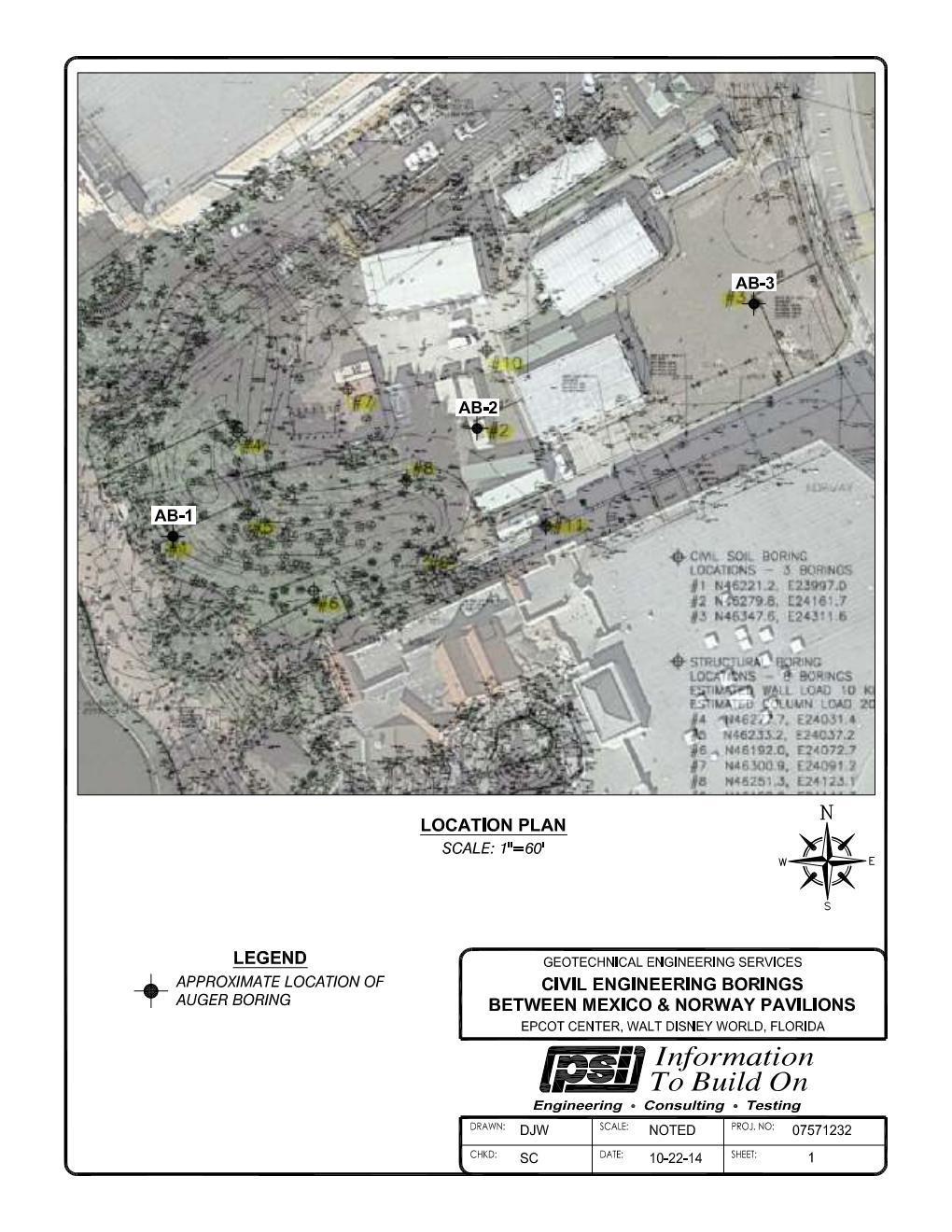
5 Figure 1: Location Map Walt Disney World, EPCOT, Between Norway and Mexico attractions, Section 30, Township 24S, Range 28E

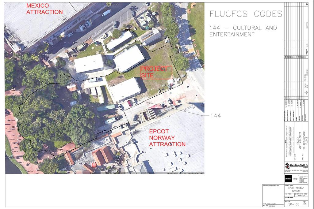
6 Figure 2: Aerial Photograph Walt Disney World, EPCOT between Mexico and Norway attractions

7 Figure 3: Aerial Photograph Walt Disney World, EPCOT between Mexico and Norway attractions


8 Figure 4: Soils Map Walt Disney World, EPCOT, between Mexico and Norway attractions
9 2.0 Project Site Description The 1.08 acre project is located between Mexico and Norway attractions of EPCOT, Walt Disney World in Orlando, Florida. Stormwater runoff from the site discharges through existing storm sewer piping to the EPCOT Master Drainage System. 3.0 Proposed Project This project proposes construction of a new building, parking, sidewalks and utilities within a 1.08 acre project area. Stormwater treatment will be provided by the construction of a new underground retention (exfiltration trench) system. 4.0 Land Use Existing Conditions Description Refer to the Pre-Development Drainage Basin Map, drawing SK-101 in Appendix 2, for the delineation of the project area. The project area discharges to existing stormwater piping, but does not receive stormwater quality treatment. Table 1: Existing Conditions Summary Existing Conditions Total Area Pervious area Impervious area 1.08 ac 0.83 ac 0.25 ac CN impervious = 98 CN pervious = 80 (from RCID Master Drainage Plan Update FOR Basin L403-17) Composite CN = Geotechnical Investigation Refer to Appendix 3 for the Geotechnical Investigation completed by PSI and dated October 23, The proposed exfiltration trench system will be located near geotechnical boring AB-2. The report found the following soil conditions at boring AB-2. These soil conditions are used in the drawdown calculations for the exfiltration trench system. Base of Effective Aquifer Elevation = 86 feet Estimated Seasonal High Water Table Elevation = 92 feet Horizontal Permeability of Effective Aquifer = 10 feet/day Vertical Permeability of Effective Aquifer = 6 feet/day Soil Porosity = 25 percent.
10 Proposed Conditions Description Refer to the Post-Development Drainage Basin Map, drawing SK-102 in Appendix 2, for the delineation of the project area. Stormwater treatment is provided in the underground exfiltration trench retention system. As shown on Table 2, part of the project area drains offsite and does not receive treatment. Nearly all of this area is composed of walkways and planters that are located on the west side of the building. This area is not used for parking. A retention system was not placed in this area due to conflicts with underground utilities and retaining walls.. Table 2: Proposed Conditions Summary DRAINS TO RETENTION DRAINS OFFSITE Total Proposed Design Conditions for the Exfiltration System (Entire Limit of Work) Total Area 0.80 ac 0.28 ac 1.08 ac Pervious area 0.13 ac 0.12 ac 0.25 ac Paved (impervious) area Roofed (impervious) area 0.33 ac 0.16 ac 0.49 ac 0.34 ac 0.00 ac 0.34 ac CN impervious = 98 CN pervious = 80 (from RCID Master Drainage Plan Update FOR Basin L403-17) Composite CN: To Retention = 95.08, Drains Offsite = 90.29, Within Limit of Work = 93.83
11 Water Quality Treatment Volume Calculations The following calculations size the underground retention system for the entire 1.08 acre limit of construction. Per Section of the South Florida Water Management District Basis of Review for Environmental Resource Permit Application, Wet Detention volume shall be provided for the first inch of runoff from the developed project, or the total runoff of 2.5 inches times the percentage of imperviousness, whichever is greater. Retention volume shall be provided equal to 50% of the above amounts computed for wet detention. Per Section 5.2.2(c), Water surface and roofed areas can be deducted from site areas only for water quality pervious/impervious calculations. Water Quality Treatment Volume Required for Entire 1.08 acre Limit of Work 1 over area 1ft V (1.08ac) ac 12in. ft 2.5 multiplied by the percent impervious Site area: total site (roof + water body) = 1.08ac 0.34ac 0. 74ac 0.49ac 2.5 multiplied by the percent impervious: 2.5inches 1. 66inches to be treated 0.74ac Volume required for retention: inches to be treated x (total site water body) 1ft V 1.66in 1.08ac ac ft 12in Treatment volume required for entire Limit of Work = ac-ft or 3,267 ft 3 Treatment volume provided = ac-ft or 3,509 ft 3 See Appendix 4 for the storage calculations The underground retention system is designed to utilize StormTech chambers and two control structures. The first control structure includes a weir that is intended to force the first flush of runoff into the isolator row chambers. The isolator row is composed of chambers like the other rows but contains extra filter fabric to allow for ease of maintenance/cleanout in the future. The control structure at the outlet end of the system includes an additional weir that backs up water into all of the chambers. The crest elevation of this weir is set at the elevation corresponding to the treatment volume of the system.
12 Runoff in excess of the treatment volume will generally discharge directly over the second control structure and bypass the treatment chambers in the system. This design is considered to be the preferred environmental solution because it does not dilute (or in the case of heavy flow, resuspend) pollutants in the treatment volume. Instead, it maximizes the pollutant loading in the treatment volume and the pollutant removal efficiency (through percolation into the ground) of the system.
13 5.0 Surface Water Management Design Parameters Computer Modeling Existing and proposed conditions are modeled with AdICPR version Precipitation 10yr/72hr = inches 100yr/72hr = inches Tailwater Conditions The exfiltration trench discharges to a new manhole that is constructed to intercept an existing 30 diameter storm pipe. The invert of the existing 30 diameter pipe is approximately 10 feet below the invert of the pipe from the exfiltration trench. It is concluded that tailwater in the existing 30 diameter pipe will not affect flow exiting the exfiltration trench. Summary of Results The results of the AdICPR routing are attached as Appendix 1 and summarized below. Pre-Development: 10yr/72hr Peak Discharge Rate = 4.53 cfs 100yr/72hr Peak Discharge Rate = 6.63 cfs Post-Development: 10yr/72hr Peak Discharge Rate = 4.73 cfs 100yr/72hr Peak Discharge Rate = 6.77 cfs Underground Retention Chambers 10yr/72hr Peak Stage = yr/72hr Peak Stage = Stormwater attenuation is not required for this project because attenuation takes place in the EPCOT master drainage system that is controlled by RCID. The calculations show that the post-development discharge rate is increased by less than 4% compared to the existing conditions.
14 Critical Data Summary Tables Land Use Development Level Breakdown within Project Limit of Work Basin ID Building (acres) Pavement (acres) Water Mgnt (acres) Pervious (acres) Total (acres) Existing Proposed Water Quality Discharge Table within Project Limit of Work WQ Volume Required (af) WQ Volume Provided (af) Overflow Elevation (feet) Allowable Discharge (cfs) See Control Elevation in Table Below Proposed Discharge Receiving Body NA NA Reedy Creek via the EPCOT Master Drainage System Design Storm Stages within Project Limit of Work Basin ID Control Elevation (feet) 10yr/72hr Stage (feet) Proposed Min. Road Elevation (feet) 100yr/72hr Stage (feet) Proposed Min FFE (feet) RETENTION NA Control Structures within Project Limit of Work Basin Type Low Water Overflow Control Receiving Body ID Control (feet) RETENTION 4 Weir NA Weir elev = Reedy Creek via the EPCOT Master Drainage System
 of the South Florida Water Management District Basis of Review for Environmental Resource Permit Application, District criteria require that gravity control devices shall be sized based upon a")
15 6.0 Drawdown Calculations Per Section 7.2(a) of the South Florida Water Management District Basis of Review for Environmental Resource Permit Application, District criteria require that gravity control devices shall be sized based upon a maximum design discharge of one half inch of the detention volume in 24 hours. Section 7.3(a) states that Dry retention/detention areas shall have mechanisms for returning the groundwater level in the area to the control elevation. The bleed-down rate for these systems is the same as in section 7.2(a). The program PONDS was used to calculate drawdown for the retention system. The geotechnical report contained in Appendix 3 is the basis for the input parameters in PONDS. See page 2 of the geotechnical report for a summary of the input parameters. Volume required for drawdown = 3,398 cubic feet (See Water Quality Treatment Volume Calculations in Section 4 of this report) Volume provided in retention system = 3,509 cubic feet (See Appendix 4 of this report) Figure 4: Input Data for Drawdown Calculation

16 Figure 5: Results of Drawdown Calculation The recovery time is 19 hours which is less than the 24 hours required. In the above calculations, the bottom of the treatment volume is taken as elevation feet which is 0.33 feet above the bottom of the rock elevation. For drawdown calculation reasons, the initial 0.33 feet of rock below the chambers is not counted in the storage volume calculations. See Appendix 4 for calculations of the amount of treatment volume provided in the system.
17 7.0 Water Use Sources Potable, Wastewater, Dewatering, Irrigation Potable Water supplier: Reedy Creek Utilities Waste water system: Reedy Creek Utilities If dewatering is needed, the contractor will submit the application to RCID at the time of construction Water Resources There will be no impacts to the floodplain. 9.0 Wetland Impacts There are no wetlands within the limit of work. Therefore, there are no wetland impacts for this project Mitigation Mitigation is not required. All wetlands impacted in this project have been mitigated for in the past Cumulative Impacts Not applicable Wetland Inventory There are no wetlands within the limit of work Threatened and Endangered Species The available information indicates that the project site does not contain preferred habitat for wetlanddependent endangered/threatened species or species of special concern.
18 APPENDIX 1 Stormwater Calculations Results From Advanced Interconnected Channel & Pond Routing Streamline Technologies, Inc.
19 AdICPR Nodal Diagram
20 Input Information ========================================================================================== ==== Basins ============================================================================== ========================================================================================== Name: EXFIL Node: EXFIL Status: Onsite Group: BASE Type: SCS Unit Hydrograph CN Unit Hydrograph: Uh256 Peaking Factor: Rainfall File: Sfwmd72 Storm Duration(hrs): Rainfall Amount(in): Time of Conc(min): Area(ac): Time Shift(hrs): 0.00 Curve Number: Max Allowable Q(cfs): DCIA(%): Name: EXISTING Node: EXISTING Status: Onsite Group: BASE Type: SCS Unit Hydrograph CN Unit Hydrograph: Uh256 Peaking Factor: Rainfall File: Sfwmd72 Storm Duration(hrs): Rainfall Amount(in): Time of Conc(min): Area(ac): Time Shift(hrs): 0.00 Curve Number: Max Allowable Q(cfs): DCIA(%): Name: OFFSITE Node: out Status: Onsite Group: BASE Type: SCS Unit Hydrograph CN Unit Hydrograph: Uh256 Peaking Factor: Rainfall File: Sfwmd72 Storm Duration(hrs): Rainfall Amount(in): Time of Conc(min): Area(ac): Time Shift(hrs): 0.00 Curve Number: Max Allowable Q(cfs): DCIA(%): 0.00 ========================================================================================== ==== Nodes =============================================================================== ========================================================================================== Name: EXFIL Base Flow(cfs): Init Stage(ft): Group: BASE Warn Stage(ft): Type: Stage/Volume Stage(ft) Volume(af) Name: out Base Flow(cfs): Init Stage(ft): Group: BASE Warn Stage(ft): Type: Time/Stage
21 Time(hrs) Stage(ft) ========================================================================================== ==== Drop Structures ===================================================================== ========================================================================================== Name: EXFIL-OUT From Node: EXFIL Length(ft): Group: BASE To Node: OUT Count: 1 UPSTREAM DOWNSTREAM Friction Equation: Automatic Geometry: Circular Circular Solution Algorithm: Most Restrictive Span(in): Flow: Both Rise(in): Entrance Loss Coef: Invert(ft): Exit Loss Coef: Manning's N: Outlet Ctrl Spec: Use dc or tw Top Clip(in): Inlet Ctrl Spec: Use dc Bot Clip(in): Solution Incs: 10 Upstream FHWA Inlet Edge Description: Circular Concrete: Square edge w/ headwall Downstream FHWA Inlet Edge Description: Circular Concrete: Square edge w/ headwall *** Weir 1 of 1 for Drop Structure EXFIL-OUT *** Count: 1 Bottom Clip(in): Type: Vertical: Mavis Top Clip(in): Flow: Both Weir Disc Coef: Geometry: Rectangular Orifice Disc Coef: TABLE Span(in): Invert(ft): Rise(in): Control Elev(ft): ========================================================================================== ==== Hydrology Simulations =============================================================== ========================================================================================== Name: 100yr-72hr Filename: F:\14\HII \D_DSGN-DATA\D01-00-DESIGN_DATA\D01-07-Civil\Stormwater design\adicpr\100yr-72hr.r32 Override Defaults: Yes Storm Duration(hrs): Rainfall File: Sfwmd72 Rainfall Amount(in): Time(hrs) Print Inc(min) Name: 10yr-72hr Filename: F:\14\HII \D_DSGN-DATA\D01-00-DESIGN_DATA\D01-07-Civil\Stormwater design\adicpr\10yr-72hr.r32 Override Defaults: Yes Storm Duration(hrs): Rainfall File: Sfwmd72 Rainfall Amount(in): Time(hrs) Print Inc(min)
22 ========================================================================================== ==== Routing Simulations ================================================================= ========================================================================================== Name: 100yr-72hr Hydrology Sim: 100yr-72hr Filename: F:\14\HII \D_DSGN-DATA\D01-00-DESIGN_DATA\D01-07-Civil\Stormwater design\adicpr\100yr-72hr.i32 Execute: Yes Restart: No Patch: No Alternative: No Max Delta Z(ft): 1.00 Delta Z Factor: Time Step Optimizer: Start Time(hrs): End Time(hrs): Min Calc Time(sec): Max Calc Time(sec): Boundary Stages: Boundary Flows: Time(hrs) Print Inc(min) Group Run BASE Yes Name: 10yr-72hr Hydrology Sim: 10yr-72hr Filename: F:\14\HII \D_DSGN-DATA\D01-00-DESIGN_DATA\D01-07-Civil\Stormwater design\adicpr\10yr-72hr.i32 Execute: Yes Restart: No Patch: No Alternative: No Max Delta Z(ft): 1.00 Delta Z Factor: Time Step Optimizer: Start Time(hrs): End Time(hrs): Min Calc Time(sec): Max Calc Time(sec): Boundary Stages: Boundary Flows: Time(hrs) Print Inc(min) Group Run BASE Yes
23 Input Hydrographs Basin Name: EXFIL Group Name: BASE Simulation: 100yr-72hr Node Name: EXFIL Basin Type: SCS Unit Hydrograph Unit Hydrograph: Uh256 Peaking Fator: Spec Time Inc (min): 1.33 Comp Time Inc (min): 1.33 Rainfall File: Sfwmd72 Rainfall Amount (in): Storm Duration (hrs): Status: Onsite Time of Conc (min): Time Shift (hrs): 0.00 Area (ac): Vol of Unit Hyd (in): Curve Number: DCIA (%): Time Max (hrs): Flow Max (cfs): 5.06 Runoff Volume (in): Runoff Volume (ft3): Basin Name: EXISTING Group Name: BASE Simulation: 100yr-72hr Node Name: EXISTING Basin Type: SCS Unit Hydrograph Unit Hydrograph: Uh256 Peaking Fator: Spec Time Inc (min): 1.33 Comp Time Inc (min): 1.33 Rainfall File: Sfwmd72 Rainfall Amount (in): Storm Duration (hrs): Status: Onsite Time of Conc (min): Time Shift (hrs): 0.00 Area (ac): Vol of Unit Hyd (in): Curve Number: DCIA (%): Time Max (hrs): Flow Max (cfs): 6.63 Runoff Volume (in): Runoff Volume (ft3): Basin Name: OFFSITE Group Name: BASE Simulation: 100yr-72hr Node Name: out Basin Type: SCS Unit Hydrograph Unit Hydrograph: Uh256 Peaking Fator: Spec Time Inc (min): 1.33 Comp Time Inc (min): 1.33
24 Rainfall File: Sfwmd72 Rainfall Amount (in): Storm Duration (hrs): Status: Onsite Time of Conc (min): Time Shift (hrs): 0.00 Area (ac): Vol of Unit Hyd (in): Curve Number: DCIA (%): Time Max (hrs): Flow Max (cfs): 1.75 Runoff Volume (in): Runoff Volume (ft3): Basin Name: EXFIL Group Name: BASE Simulation: 10yr-72hr Node Name: EXFIL Basin Type: SCS Unit Hydrograph Unit Hydrograph: Uh256 Peaking Fator: Spec Time Inc (min): 1.33 Comp Time Inc (min): 1.33 Rainfall File: Sfwmd72 Rainfall Amount (in): Storm Duration (hrs): Status: Onsite Time of Conc (min): Time Shift (hrs): 0.00 Area (ac): Vol of Unit Hyd (in): Curve Number: DCIA (%): Time Max (hrs): Flow Max (cfs): 3.53 Runoff Volume (in): Runoff Volume (ft3): Basin Name: EXISTING Group Name: BASE Simulation: 10yr-72hr Node Name: EXISTING Basin Type: SCS Unit Hydrograph Unit Hydrograph: Uh256 Peaking Fator: Spec Time Inc (min): 1.33 Comp Time Inc (min): 1.33 Rainfall File: Sfwmd72 Rainfall Amount (in): Storm Duration (hrs): Status: Onsite Time of Conc (min): Time Shift (hrs): 0.00 Area (ac): Vol of Unit Hyd (in): Curve Number: DCIA (%): Time Max (hrs): Flow Max (cfs): 4.53
25 Runoff Volume (in): Runoff Volume (ft3): Basin Name: OFFSITE Group Name: BASE Simulation: 10yr-72hr Node Name: out Basin Type: SCS Unit Hydrograph Unit Hydrograph: Uh256 Peaking Fator: Spec Time Inc (min): 1.33 Comp Time Inc (min): 1.33 Rainfall File: Sfwmd72 Rainfall Amount (in): Storm Duration (hrs): Status: Onsite Time of Conc (min): Time Shift (hrs): 0.00 Area (ac): Vol of Unit Hyd (in): Curve Number: DCIA (%): Time Max (hrs): Flow Max (cfs): 1.22 Runoff Volume (in): Runoff Volume (ft3): 8957
26 Output Summary Post-development Conditions Max Time Max Warning Max Delta Max Surf Max Time Max Max Time Max Name Group Simulation Stage Stage Stage Stage Area Inflow Inflow Outflow Outflow hrs ft ft ft ft2 hrs cfs hrs cfs EXFIL BASE 100yr-72hr out BASE 100yr-72hr EXFIL BASE 10yr-72hr out BASE 10yr-72hr
27 APPENDIX 2 Pre- and Post-Development RCID Drainage Basin Maps
28
29
30
31 APPENDIX 3 Geotechnical Report
32
33
34
35
36
37
38 APPENDIX 4 StormTech DC-780 Cumulative Storage Volume Calculations

39 The above table shows storage provided between the bottom and top of rock elevation is 3498 cf. For drawdown calculation reasons, the initial 0.33 feet of rock below the chambers is not counted in the storage volume calculations. In other words, the gravel bed from elevation and is not counted in the storage calculations. Subtracting this 0.33 feet or 207 cubic feet storage, the storage volume is 3291 cubic feet of storage provided. Storage that is provided in the 12 diameter storm piping that discharges into the system can be added to this volume. The volume provided in the 277 feet of 12 diameter storm piping, all of which is below the controlling weir elevation of the system, is 218 cubic feet. The total storage provided in the system is therefore 3509 cubic feet storage.
40 APPENDIX 5 Pre- and Post-Development FLUCCS Maps
41
42
Istokpoga Marsh Watershed Improvement District (IMWID) Minor Impoundment Project. May 23, 2012
 Minor Impoundment Project. May 23, 2012") STORMWATER INFORMATION AND CALCULATIONS FOR ENVIRONMENTAL RESOURCE PERMIT Istokpoga Marsh Watershed Improvement District (IMWID) Minor Impoundment Project Prepared by Chastain-Skillman, Inc. Prepared for
STORMWATER INFORMATION AND CALCULATIONS FOR ENVIRONMENTAL RESOURCE PERMIT Istokpoga Marsh Watershed Improvement District (IMWID) Minor Impoundment Project Prepared by Chastain-Skillman, Inc. Prepared for
DRAINAGE REPORT FOR. Creeks Crossing
 DRAINAGE REPORT FOR Creeks Crossing LOCATED AT: Galloway Road North Lakeland, Florida 33810 PREPARED FOR: Southern Homes/LM Properties OWNER: Heritage Investments of Polk, LLC PREPARED BY: SUBMITTED TO:
Summary of Detention Pond Calculation Canyon Estates American Canyon, California
 July 15, 2015 Bellecci & Associates, Inc Summary of Detention Pond Calculation Canyon Estates American Canyon, California 1. Methodology: Method: Unit Hydrograph Software: Bentley Pond Pack Version 8i
INFLOW DESIGN FLOOD CONTROL SYSTEM PLAN PLANT BARRY ASH POND ALABAMA POWER COMPANY
 INFLOW DESIGN FLOOD CONTROL SYSTEM PLAN PLANT BARRY ASH POND ALABAMA POWER COMPANY Section 257.82 of EPA s regulations requires the owner or operator of an existing or new CCR surface impoundment or any
HYDROLOGIC-HYDRAULIC STUDY ISABELLA OCEAN RESIDENCES ISLA VERDE, CAROLINA, PR
 HYDROLOGIC-HYDRAULIC STUDY ISABELLA OCEAN RESIDENCES ISLA VERDE, CAROLINA, PR 1 INTRODUCTION 1.1 Project Description and Location Isabella Ocean Residences is a residential development to be constructed
INFLOW DESIGN FLOOD CONTROL SYSTEM PLAN 40 C.F.R. PART PLANT YATES ASH POND 3 (AP-3) GEORGIA POWER COMPANY
 GEORGIA POWER COMPANY") INFLOW DESIGN FLOOD CONTROL SYSTEM PLAN 40 C.F.R. PART 257.82 PLANT YATES ASH POND 3 (AP-3) GEORGIA POWER COMPANY EPA s Disposal of Coal Combustion Residuals from Electric Utilities Final Rule (40 C.F.R.
INFLOW DESIGN FLOOD CONTROL SYSTEM PLAN 40 C.F.R. PART 257.82 PLANT YATES ASH POND 3 (AP-3) GEORGIA POWER COMPANY EPA s Disposal of Coal Combustion Residuals from Electric Utilities Final Rule (40 C.F.R.
Continuous Simulation Modeling of Stormwater Ponds, Lakes, & Wetlands: A BUILT-IN APPLICATION OF PONDS 3.2
 Continuous Simulation Modeling of Stormwater Ponds, Lakes, & Wetlands: A BUILT-IN APPLICATION OF PONDS 3.2 PRESENTED AT THE SFWMD WORKSHOP PRE-DEVELOPMENT VERSUS POST DEVELOPMENT RUNOFF VOLUME ANALYSIS
EXAMPLE Stormwater Management Plans w/ CSS BMP Sizing Calculator (v2.1)
") 525 Golden Gate Avenue, 11th Floor San Francisco, CA 94102 EXAMPLE Stormwater Management Plans w/ CSS BMP Sizing Calculator (v2.1) The following example Stormwater Management Plans (SMPs) are provided
525 Golden Gate Avenue, 11th Floor San Francisco, CA 94102 EXAMPLE Stormwater Management Plans w/ CSS BMP Sizing Calculator (v2.1) The following example Stormwater Management Plans (SMPs) are provided
SITE DESIGN ENGINEERING, LLC. 11 Cushman Street, Middleboro, MA P: F:
 INTRODUCTION This drainage report was prepared for the proposed site re-development at in Burlington, Massachusetts. The project site is approximately 1.05± acres consisting of approximately 70% impervious
GENERAL AND FLOODING STANDARDS SUBMISSION BRUNSWICK LAYOVER FACILITY BRUNSWICK, MAINE PREPARED FOR:
 APPENDIX H GENERAL AND FLOODING STANDARDS SUBMISSION BRUNSWICK LAYOVER FACILITY BRUNSWICK, MAINE PREPARED FOR: NORTHERN NEW ENGLAND PASSENGER RAIL AUTHORITY (NNEPRA) 75 WEST COMMERCIAL STREET, SUITE 104
Sizing Calculations and Design Considerations for LID Treatment Measures
 SCVURPPP C.3 Workshop December 18, 2012 Sizing Calculations and Design Considerations for LID Treatment Measures Jill Bicknell, P.E., EOA, Inc. Santa Clara Valley Urban Runoff Pollution Prevention Program
Chapter 6. Hydrology. 6.0 Introduction. 6.1 Design Rainfall
 6.0 Introduction This chapter summarizes methodology for determining rainfall and runoff information for the design of stormwater management facilities in the City. The methodology is based on the procedures
INFLOW DESIGN FLOOD CONTROL SYSTEM PLAN 40 C.F.R. PART PLANT BOWEN ASH POND 1 (AP-1) GEORGIA POWER COMPANY
 GEORGIA POWER COMPANY") INFLOW DESIGN FLOOD CONTROL SYSTEM PLAN 40 C.F.R. PART 257.82 PLANT BOWEN ASH POND 1 (AP-1) GEORGIA POWER COMPANY EPA s Disposal of Coal Combustion Residuals from Electric Utilities Final Rule (40 C.F.R.
INFLOW DESIGN FLOOD CONTROL SYSTEM PLAN 40 C.F.R. PART 257.82 PLANT BOWEN ASH POND 1 (AP-1) GEORGIA POWER COMPANY EPA s Disposal of Coal Combustion Residuals from Electric Utilities Final Rule (40 C.F.R.
Appendix B. Storm Drain System Data
 MENIFEE VALLEY CAMPUS MASTER PLAN FINAL EIR MT. SAN JACINTO COMMUNITY COLLEGE DISTRICT Appendix Appendix B. Storm Drain System Data June 2017 MENIFEE VALLEY CAMPUS MASTER PLAN FINAL EIR MT. SAN JACINTO
Hydrologic Study Report for Single Lot Detention Basin Analysis
 Hydrologic Study Report for Single Lot Detention Basin Analysis Prepared for: City of Vista, California August 18, 2006 Tory R. Walker, R.C.E. 45005 President W.O. 116-01 01/23/2007 Table of Contents Page
Treatment Volume: Curve Numbers. Composite CN or Not? Treatment Volume: Curve Numbers. Treatment Volume: Calculation. Treatment Volume: Calculation
 Stormwater Engineering Bioretention Design Bill Hunt, PE, Ph.D. Extension Specialist & Assistant Professor NCSU-BAE www.bae.ncsu.edu/stormwater Bioretention Design Six Step Process 1 Determine Volume to
Inflow Design Flood Control System Plan
 Inflow Design Flood Control System Plan For Compliance with the Coal Combustion Residuals Rule (40 CFR Part 257) Cherokee Station - CCR Surface Impoundments Public Service Company of Colorado Denver, Colorado
ENVIRONMENTAL RESOURCE PERMIT APPLICATION
 ENVIRONMENTAL RESOURCE PERMIT APPLICATION SOUTHWEST FLORIDA WATER MANAGEMENT DISTRICT 2379 BROAD STREET, BROOKSVILLE, FL 34604-6899 (352) 796-7211 OR FLORIDA WATS 1 (800) 423-1476 SECTION E INFORMATION
INFLOW DESIGN FLOOD CONTROL SYSTEM PLAN 40 C.F.R. PART PLANT DANIEL ASH POND B MISSISSIPPI POWER COMPANY
 INFLOW DESIGN FLOOD CONTROL SYSTEM PLAN 40 C.F.R. PART 257.82 PLANT DANIEL ASH POND B MISSISSIPPI POWER COMPANY EPA s Disposal of Coal Combustion Residuals from Electric Utilities Final Rule (40 C.F.R.
SAN GORGONIO PASS CAMPUS - PHASE I
 SAN GORGONIO PASS CAMPUS - PHASE I Banning, CA DRAINAGE STUDY June 16, 2010 Reference 106-195 PREPARED BY: Encompass Associates, Inc. 5699 Cousins Place Rancho Cucamonga, CA 91737 909-684-0093 Fax-909-586-6979
Inflow Design Flood Control System Plan
 Inflow Design Flood Control System Plan For Compliance with the Coal Combustion Residuals Rule (40 CFR Part 257) Valmont Station - CCR Surface Impoundments Public Service Company of Colorado Denver, Colorado
APPENDIX G HYDRAULIC GRADE LINE
 Storm Drainage 13-G-1 APPENDIX G HYDRAULIC GRADE LINE 1.0 Introduction The hydraulic grade line is used to aid the designer in determining the acceptability of a proposed or evaluation of an existing storm
SOUTH FLORIDA WATER MANAGEMENT DISTRICT. Question 13: Wetlands
 SOUTH FLORIDA WATER MANAGEMENT DISTRICT Question 13: Wetlands 1. The wetland responses and topographical data provided in the ADA for the 520- acre project site are conceptual in nature. The referenced
4.8. Subsurface Infiltration
 4.8. Subsurface Infiltration Subsurface infiltration systems are designed to provide temporary below grade storage infiltration of storm water as it infiltrates into the ground. Dry wells, infiltration
Municipal Stormwater Ordinances Summary Table
 APPENDIX F Municipal Ordinances Summary Table Municipality Abington Bryn Athyn Borough Hatboro Borough Ordinance, SALDO Runoff equals pre post Erosion Sediment Control Water Quality Requirements Any which
PART 3 - STANDARDS FOR SEWERAGE FACILITIES DESIGN OF STORM SEWERS
 PART 3 - STANDARDS FOR SEWERAGE FACILITIES 3.3 - DESIGN OF STORM SEWERS 3.301 Design of Storm Sewers A. General Information B. Investigations and Surveys C. Special Projects 3.302 Design Criteria for Storm
Rhode Island Stormwater Design and Installations Standards Manual
 Rhode Island Stormwater Design and Installations Standards Manual Public Workshop Required Management Volume Calculations and Redevelopment Considerations March 22, 2011 Presentation Outline Recap of How
LID PLANTER BOX MODELING
 LID PLANTER BOX MODELING Clear Creek Solutions, Inc., 2010 Low Impact Development (LID) planter boxes are small, urban stormwater mitigation facilities. They are rain gardens in a box. WWHM4 provides the
COON CREEK WATERSHED DISTRICT PERMIT REVIEW. Spring Lake Park Schools Westwood Middle School st Avenue NE, Spring Lake Park, MN 55432
 PAN 16-112, Westwood Middle School, Page 1 of 6 COON CREEK WATERSHED DISTRICT PERMIT REVIEW MEETING DATE: August 22, 2016 AGENDA NUMBER: 10 FILE NUMBER: 16-112 ITEM: Westwood Middle School RECOMMENDATION:
Decatur, Georgia Stormwater Management Policy Guidelines. DRAFT November 5, 2014
 Decatur, Georgia Stormwater Management Policy Guidelines Stormwater Management Policy Guidelines Decatur, Georgia STORMWATER MANAGEMENT POLICY GUIDELINES 1.0 Introduction... 3 2.0 Determining Predevelopment
E. STORMWATER MANAGEMENT
 E. STORMWATER MANAGEMENT 1. Existing Conditions The Project Site is located within the Lower Hudson Watershed. According to the New York State Department of Environmental Conservation (NYSDEC), Lower Hudson
Pre-Treatment Bioretention Cells Bioswales IOWA STORMWATER MANAGEMENT MANUAL DECEMBER 16, 2015
 Pre-Treatment Bioretention Cells Bioswales IOWA STORMWATER MANAGEMENT MANUAL DECEMBER 16, 2015 Urban Runoff Background How we got here What Problem?? Provenance of the Problem Unified Sizing Criteria What
6.0 Runoff. 6.1 Introduction. 6.2 Flood Control Design Runoff
 October 2003, Revised February 2005 Chapter 6.0, Runoff Page 1 6.1 Introduction 6.0 Runoff The timing, peak rates of discharge, and volume of stormwater runoff are the primary considerations in the design
Considerations In Estimating Tailwater Elevations
 Considerations In Estimating Tailwater Elevations by Alphonse (Al) J. Stewart, P.E., President www.suncam.com Page 1 of 39 ************************************************************************ This
Hydrology Study. Ascension Heights Subdivision Ascension Drive at Bel Aire Road San Mateo, California (Unincorporated)
") Hydrology Study Ascension Heights Subdivision Ascension Drive at Bel Aire Road San Mateo, California (Unincorporated) Prepared for San Mateo Real Estate & Construction March 9, 21 Rev. 1 11-8-211 Rev.
Hydrology Study Ascension Heights Subdivision Ascension Drive at Bel Aire Road San Mateo, California (Unincorporated) Prepared for San Mateo Real Estate & Construction March 9, 21 Rev. 1 11-8-211 Rev.
Infiltration Guidelines
 Appendix E Infiltration Guidelines As a stormwater management method, infiltration means retaining or detaining water within soils to reduce runoff. Infiltration can be a cost-effective method to manage
Project Drainage Report
 Design Manual Chapter 2 - Stormwater 2A - General Information 2A-4 Project Drainage Report A. Purpose The purpose of the project drainage report is to identify and propose specific solutions to stormwater
4.8. Subsurface Infiltration
 4.8. Subsurface Infiltration Subsurface infiltration systems are designed to provide temporary below grade storage infiltration of stormwater as it infiltrates into the ground. Dry wells, infiltration
APPENDIX IV. APPROVED METHODS FOR QUANTIFYING HYDROLOGIC CONDITIONS OF CONCERN (NORTH ORANGE COUNTY)
") APPENDIX IV. APPROVED METHODS FOR QUANTIFYING HYDROLOGIC CONDITIONS OF CONCERN (NORTH ORANGE COUNTY) Hydromodification design criteria for the North Orange County permit area are based on the 2- yr, 24-hr
APPENDIX IV. APPROVED METHODS FOR QUANTIFYING HYDROLOGIC CONDITIONS OF CONCERN (NORTH ORANGE COUNTY) Hydromodification design criteria for the North Orange County permit area are based on the 2- yr, 24-hr
Stormwater Drainage Criteria Manual. City Of Clearwater Engineering Department Effective July 1, 2015
 Stormwater Drainage Criteria Manual City Of Clearwater Engineering Department Effective July 1, 2015 Engineering Department STORMWATER DRAINAGE CRITERIA MANUAL Table of Contents STORMWATER DRAINAGE CRITERIA
INFLOW DESIGN FLOOD CONTROL SYSTEM PLAN 40 C.F.R. PART PLANT YATES ASH POND B (AP-B ) GEORGIA POWER COMPANY
 GEORGIA POWER COMPANY") INFLOW DESIGN FLOOD CONTROL SYSTEM PLAN 40 C.F.R. PART 257.82 PLANT YATES ASH POND B (AP-B ) GEORGIA POWER COMPANY EPA s Disposal of Coal Combustion Residuals from Electric Utilities Final Rule (40 C.F.R.
INFLOW DESIGN FLOOD CONTROL SYSTEM PLAN 40 C.F.R. PART 257.82 PLANT YATES ASH POND B (AP-B ) GEORGIA POWER COMPANY EPA s Disposal of Coal Combustion Residuals from Electric Utilities Final Rule (40 C.F.R.
Stormwater Local Design Manual For Houston County, Georgia
 Stormwater Local Design Manual For Houston County, Georgia Adopted November 15, 2005 TABLE OF CONTENTS 1. FORWARD... 1 2. GENERAL LEVEL OF SERVICE STANDARDS... 2 2.1. DETENTION REQUIREMENTS... 2 2.1.1.
Appendix G Preliminary Hydrology Study
 Appendix G Preliminary Hydrology Study Preliminary Hydrology Study VESTING TTM 72608 Long Beach, CA Prepared for: The Long Beach Project, LLC 888 San Clemente, Suite 100 New Port Beach, CA May 28, 2014
Stormwater Volume and Treatment Methods Simplifying the Numbers. IAFSM March 10, Presented by: Tom Powers P.E., CFM, LEED AP, CPESC
 Stormwater Volume and Treatment Methods Simplifying the Numbers IAFSM March 10, 2011 Presented by: Tom Powers P.E., CFM, LEED AP, CPESC Introduction GOALS: Improve understanding of Rate and Volume (Quantity)
Index. Page numbers followed by f indicate figures.
 Index Aerodynamic method, 103, 110 111 Algae, 131, 173, 175 Alternate depth, 88 Alternating block method, 132, 140 141 Attenuation, 106, 107f, 118, 120 Page numbers followed by f indicate figures. Baseflow
FIRM NAME DESIGNER: CHECKER: DATE: FPID #: DESCRIPTION: COUNTY: DRAINAGE DESIGN CHECKLIST. Designers Initials. Checkers Initials.
 I. Drainage Report A. Executive Summary - Brief Overview of Project Drainage Design B. Project Description 1. Existing Conditions 2. Proposed Project Conditions 3. Project Justification Narrative - Basin
Stormwater Management Criteria
 FOR OFFICE USE ONLY Stormwater Management Criteria Form #PWU005 (rev. 11/16) Approving Agency Performance Standards Applicability for Control of Stormwater Pollution Applicability for Control of Peak Runoff
MODEL Stormwater Local Design Manual. City of Centerville
 MODEL Stormwater Local Design Manual City of Centerville Adopted December 6, 2005 TABLE OF CONTENTS 1. FORWARD... 1 2. GENERAL LEVEL OF SERVICE STANDARDS... 1 2.1. DETENTION REQUIREMENTS... 1 2.1.1. Discharge
RE: Final Drainage Letter: Northwest Aurora Alley Improvements 2016
 April 12, 2016 Mr. Craig Perl, P.E. Senior Engineer City of Aurora Public Works Department 15151 E. Alameda Parkway Aurora, CO 80012 RE: Final Drainage Letter: Northwest Aurora Alley Improvements 2016
STORMWATER MANAGEMENT DESIGN REPORT
 January, 2018 STORMWATER MANAGEMENT DESIGN REPORT (To be later inserted into the Drainage Design Documentation) Note: This report outline is not all-inclusive. There may be situations when information
2C-12 Detention Basin Outlet Structures
 Iowa Stormwater Management Manual 2C-12 2C-12 Detention Basin Outlet Structures A. Introduction The methods described in Section 2C-9 are used to estimate the volume of the detention storage. The second
Boise City Public Works General Drainage Plan Review Requirements Checklist
 Boise City Public Works General Drainage Plan Review Requirements Checklist Development Name Bldg. Permit # Drainage Reviewer Site Address Initial Review Date ODI Number Designer Company Name Treated Acres
At least 2 feet above the seasonal high water table Overflow path or structure provided
 General Conditions Map of proposed subwatershed to each subbasin, including total area and CN Design Flow or Design Volume to each STF, as appropriate Operation and Maintenance instructions for each STF
HYDROLOGY STUDY PREPARED FOR: MARKHAM PERRIS LLC 302 WEST FIFTH STREET, SUITE 103 SAN PEDRO, CA (310) FOR THE PROJECT:
 FOR THE PROJECT:") HYDROLOGY STUDY PREPARED FOR: MARKHAM PERRIS LLC 302 WEST FIFTH STREET, SUITE 103 SAN PEDRO, CA 90731 (310) 241-2992 FOR THE PROJECT: PERRIS VALLEY COMMERCE CENTER BUILDING PERRIS, CALIFORNIA PROJECT NUMBER:
HYDROLOGY STUDY PREPARED FOR: MARKHAM PERRIS LLC 302 WEST FIFTH STREET, SUITE 103 SAN PEDRO, CA 90731 (310) 241-2992 FOR THE PROJECT: PERRIS VALLEY COMMERCE CENTER BUILDING PERRIS, CALIFORNIA PROJECT NUMBER:
Hydrology Study. For Bella Terrazza Portion of Lot 1, Block 39, Subdivision of S Tract, Rancho El Cajon El Cajon, CA 92021
 Hydrology Study For Bella Terrazza Portion of Lot 1, Block 39, Subdivision of S Tract, Rancho El Cajon El Cajon, CA 92021 Prepared for Daryl Priest - Priest Development Corporation 124 West Main Street,
DRAINAGE DESIGN DOCUMENTATION
 June, 2017 DRAINAGE DESIGN DOCUMENTATION (An expansion of the Stormwater Management Design Report) Note: This report outline is not all-inclusive. There may be situations when information not included
DIVISION 5 STORM DRAINAGE CRITERIA
 DIVISION 5 STORM DRAINAGE CRITERIA Section 5.01 GENERAL The following storm drainage design criteria shall apply to all storm drainage designs in the City. Additional design criteria are specified in the
CASE STUDIES: BMPTRAINS MODEL
 CASE STUDIES: BMPTRAINS MODEL B Y : M A R T Y W A N I E L I S T A A N D E R I C L I V I N G S T O N August, 2016 Escambia County ACKNOWLEDGEMENTS The Low Impact Design BMP workshops were presented on August
Chatham Park Stormwater Manual
 Chatham Park Stormwater Manual Table of Contents A. Introduction... 2 B. Calculation Methods... 2 C. BMP Design Standards... 3 D. Compliance Points... 3 E. Critical Environmental Resources... 3 F. Submittal
CRITERIA FOR STORMWATER DESIGN
 ..CHAPTER.. CRITERIA FOR STORMWATER DESIGN 2.1 Integrated Site Design Approach 2.1.1 Introduction This chapter represents the requirements, policies and other guidance for stormwater management design
Porous Pavement Flow Paths
 POROUS PAVEMENT MODELING Clear Creek Solutions, Inc., 2010 Porous pavement includes porous asphalt or concrete and grid/lattice systems (nonconcrete) and paving blocks. The use of any of these types of
SECTION 4 SURFACE WATER MANAGEMENT DESIGN AND CONSTRUCTION REQUIREMENTS
 SECTION 4 SURFACE WATER MANAGEMENT DESIGN AND CONSTRUCTION REQUIREMENTS Page 4-1 INTRODUCTION 4-3 4-1.01 Applicability of VMCs 14.24, 14.25, 14.26 4-4 4-1.02 Minimum Requirements - Projects Below Threshold
A. Manufactured Treatment Device Characteristics
 Requirements for Interim Certification of Hydrodynamic Sedimentation Devices for Total Suspended Solids Based on Laboratory Testing DRAFT April 28, 2009 The New Jersey Stormwater Management Rules at N.J.A.C.
BMP 6.4.4: Infiltration Trench
 BMP 6.4.4: Infiltration Trench An Infiltration Trench is a leaky pipe in a stone filled trench with a level bottom. An Infiltration Trench may be used as part of a larger storm sewer system, such as a
CACHE VALLEY STORM WATER DESIGN STANDARDS. As Amended by Logan City November 2010
 CACHE VALLEY STORM WATER DESIGN STANDARDS As Amended by Logan City November 2010 Updated November 2010 Table of Contents A. Definitions... 3 B. Design Requirements... 5 1. Storm Event... 5 2. Allowable
Gwinnett County Stormwater System Assessment Program
 Gwinnett County Stormwater System Assessment Program Jonathan Semerjian, PE Dept. of Water Resources Stormwater Management Sam Fleming, PE Dewberry Presentation Overview Project Background Drivers Enhanced
Hydrologic and Hydraulic Analysis Report Mountaineer Plant Bottom Ash Pond Complex New Haven, West Virginia
 Hydrologic and Hydraulic Analysis Report Mountaineer Plant Bottom Ash Pond Complex New Haven, West Virginia September 2015 Terracon Project Number: N4155129 Prepared for: American Electric Power 1 Riverside
Sunset Circle Vegetated Swale and Infiltration Basin System Monitoring Report: Rainy Seasons and
 Sunset Circle Vegetated Swale and Infiltration asin System Monitoring Report: Rainy Seasons 2012-13 and 2013-14 bstract Site Summary Project Features Sunset Circle Vegetated swales and infiltration basins
Chapter H. Introduction to Surface Water Hydrology and Drainage for Engineering Purposes
 Chapter H. Introduction to Surface Water Hydrology and Drainage for Engineering Purposes As seen in Figure H.1, hydrology is a complex science that deals with the movement of water between various stages
Urbanizing Watersheds: Green Infrastructure and Hydrologic Function. Jay Dorsey, PE, PhD ODNR-DSWR October 30, 2014
 Urbanizing Watersheds: Green Infrastructure and Hydrologic Function Jay Dorsey, PE, PhD ODNR-DSWR October 30, 2014 Green Infrastructure Objectives Intentional about maintaining/replacing ecosystem functions
Jamestown Public Schools Bush Elementary Addition and Alterations
 ADDENDUM TO THE STORMWATER POLLUTION PREVENTION PLAN For the Jamestown Public Schools Bush Elementary Addition and Alterations Jamestown, New York Chautauqua County February, 2014 Clark Patterson Lee DESIGN
Analysis of Runoff Reduction and Hydrologic Cycle Utilizing LID Concepts
 Maine Stormwater Conference (Portland, ME, 2015) Analysis of Runoff Reduction and Hydrologic Cycle Utilizing LID Concepts Park Jongpyo, Lee Kyoungdo: HECOREA. INC Shin Hyunsuk: Busan National University
HYDROLOGIC CONSIDERATIONS. 22 nd Annual Nonpoint Source Pollution Conference Saratoga Springs, NY
 LOW IMPACT DEVELOPMENT HYDROLOGIC CONSIDERATIONS 22 nd Annual Nonpoint Source Pollution Conference Saratoga Springs, NY May 18, 2011 PRESENTATION AGENDA Introduction Definitions Discuss Impacts to Hydrologic
Activity Calculating Property Drainage
 Page 1 of 5 Activity 2.3.11 Calculating Property Drainage Introduction When a property is developed, it is important to understand that changes to watershed characteristics (i.e., land use, slope, soil
Hydrologic Calibration:
 Hydrologic Calibration: UPDATE OF EFFECTIVE HYDROLOGY FOR MARYS CREEK October 2010 Agenda Background Hydrologic model Calibrated rainfall Hydrologic calibration 100 year discharges, Existing Conditions
Stormwater Management Studies PDS Engineering Services Division ES Policy # 3-01
 Stormwater Management Studies PDS Engineering Services Division Revised Date: 2/28/08 INTRODUCTION The City of Overland Park requires submission of a stormwater management study as part of the development
Water Quality Management Plan
 Water Quality Management Plan For El Centro Aquatic Center Park Avenue between 4 th Street and 6 th Street August 5, 216 Prepared by Arsalan Dadkhah, Ph.D., PE (RCE 4156) D-MAX Engineering, Inc. 722 Trade
Software Applications for Runoff Hydrological Assessment
 Bulletin UASVM Horticulture, 67(2)/2010 Print ISSN 1843-5254; Electronic ISSN 1843-5394 Software Applications for Runoff Hydrological Assessment Severin CAZANESCU 1), Sorin CIMPEANU 1), Oana GUI 2), Dana
Effect of the Underlying Groundwater System on the Rate of Infiltration of Stormwater Infiltration Structures.
 Effect of the Underlying Groundwater System on the Rate of Infiltration of Stormwater Infiltration Structures. Presented at: Storm Water Infiltration & Groundwater Recharge A Conference on Reducing Runoff
Extended Detention Basin (EDB) Sedimentation Facility
 Sedimentation Facility") Extended Detention Basin (EDB) Sedimentation Facility Description An extended detention basin (EDB) is a sedimentation basin designed to totally drain dry sometime after stormwater runoff ends. It is an
Extended Detention Basin (EDB) Sedimentation Facility Description An extended detention basin (EDB) is a sedimentation basin designed to totally drain dry sometime after stormwater runoff ends. It is an
CITY UTILITIES DESIGN STANDARDS MANUAL
 CITY UTILITIES DESIGN STANDARDS MANUAL () September 2017 Page Chapter 1 Acronyms and Definitions 1.01 Purpose 1 1.02 Acronyms 1 1.03 Definitions 3 Chapter 2 Introduction 2.01 Purpose 1 2.02 Applicability
SECTION 2 DESIGN CRITERIA
 SECTION 2 DESIGN CRITERIA 2.1 GENERAL The following criteria will be utilized by the District Engineer, and/or a consultant, in the review of development plans for recommending approval of the proposed
APPENDIX C PRELIMINARY HYDROLOGY AND WATER QUALITY STUDY (BWE 2017)
") UC San Diego Voigt Parking Structure Draft Initial Study and Mitigated Negative Declaration October 2017 APPENDIX C PRELIMINARY HYDROLOGY AND WATER QUALITY STUDY (BWE 2017) UC San Diego Voigt Parking Structure
UC San Diego Voigt Parking Structure Draft Initial Study and Mitigated Negative Declaration October 2017 APPENDIX C PRELIMINARY HYDROLOGY AND WATER QUALITY STUDY (BWE 2017) UC San Diego Voigt Parking Structure
SECTION STORM DRAINAGE DESIGN, GRADING, AND WATER QUALITY TECHNICAL CRITERIA TABLE OF CONTENTS PAGE 402 STORM DRAINAGE DESIGN CRITERIA 400-1
 CITY OF THORNTON Standards and Specifications Revised: October 2012 SECTION 400 - STORM DRAINAGE DESIGN, GRADING, AND WATER QUALITY TECHNICAL CRITERIA TABLE OF CONTENTS PAGE 401 GENERAL PROVISIONS 400-1
ROLES AND RESPONSIBILITIES Small Pond Approval. SWM MD-378 Pond Checklist Training 10/17/07. Exemptions EMBANKMENT HEIGHT. Height of Dam Weir Wall
 SWM MD-378 Pond Checklist Training 10/17/07 Ken Wolfe Warren Johnson USDA, NRCS Frederick, Maryland ROLES AND RESPONSIBILITIES Small Pond Approval MDE, WMA, Dam Safety Division Authority (COMAR 26.17.04.03)
10.0 Storm Sewer Systems
 October 2003 Chapter 10.0, Storm Sewer Systems Page 1 10.0 Storm Sewer Systems 10.1 Introduction A storm sewer system consists of a system of inlets, pipes, manholes, junctions, cleanouts, outlets, and
Chapter 3 Calculating the WQCV and Volume Reduction
 Contents 1.0 Introduction... 1 2.0 Hydrologic Basis of the WQCV... 1 2.1 Development of the WQCV... 1 2.2 Optimizing the Capture Volume... 3 2.3 Attenuation of the WQCV (BMP Drain Time)... 4 2.4 Excess
Stormwater Management and Sediment and Erosion Control Plan Review Checklist for Design Professionals
 Page 1 of 7 Florence County MS4 Stormwater Management and Sediment and Erosion Control Plan Review Checklist for Design Professionals Please indicate the location and page number(s) where each item below
Module 10b: Gutter and Inlet Designs and Multiple Design Objectives
 Module 10b: Gutter and Inlet Designs and Multiple Design Objectives Bob Pitt University of Alabama and Shirley Clark Penn State Harrisburg Evening traffic plows through high water at the intersection of
The City of Cocoa (City) is located in east
 is located in east") FWRJ Reclaimed Water and Stormwater: A Perfect Pair to Meet Total Maximum Daily Load Wasteload Allocations? Danielle Honour, James Wittig, John A. Walsh, and Don Stevens Danielle Honour, P.E., D.WRE, and
FWRJ Reclaimed Water and Stormwater: A Perfect Pair to Meet Total Maximum Daily Load Wasteload Allocations? Danielle Honour, James Wittig, John A. Walsh, and Don Stevens Danielle Honour, P.E., D.WRE, and
Stormwater Management Fact Sheet: Porous Pavement
 Stormwater Management Fact Sheet: Porous Pavement Description Porous pavement is a permeable pavement surface with an underlying stone reservoir that temporarily stores surface runoff before infiltrating
City of Oakland. Public Works Agency Standards STORM DRAINAGE DESIGN GUIDELINES. Engineering Design & ROW Management Division
 City of Oakland PUBLIC WORKS AGENCY 250 FRANK H. OGAWA PLAZA 4 TH FLOOR OAKLAND, CALIFORNIA 94612 (510) 238-3437 FAX (510) 238-7227 TTD (510) 238-3254 Public Works Agency Standards STORM DRAINAGE DESIGN
APPENDIX L Hydrology and Stormwater Pond Analysis
 APPENDIX L Hydrology and Stormwater Pond Analysis This page is left intentionally blank. Hydrology and Stormwater Pond Analysis Liesch Associates, Inc. June 1, 2012 Minneapolis-St. Paul International Airport
Table of Contents. 5-5 Release Rates Year Allowable Release Rate WQCV Release Rate EURV Release Rate...
 Chapter 5 Table of Contents 5-1 Introduction... 1 5-1-1 Stormwater Quality Considerations... 1 5-1-2 Stormwater Volume Considerations... 2 5-1-3 Downstream Impacts... 2 5-2 Requirements... 2 5-2-1 General
Chapter 3 Dispersion BMPs
 Chapter 3 Dispersion BMPs 3.1 BMP L611 Concentrated Flow Dispersion 3.1.1 Purpose and Definition Dispersion of concentrated flows from driveways or other pavement through a vegetated pervious area attenuates
Stormwater Retention Pond Recovery Analysis
 Stormwater Retention Pond Recovery Analysis By Nicolas E Andreyev The first in a series of courses on Green Drainage Design www.suncam.com Page 1 of 33 Forward To design a stormwater retention pond, one
THE CROSSROADS IN WINCHESTER 4. DRAINAGE PLAN. 4. Drainage Plan. a. Drainage Plan Description
 THE CROSSROADS IN WINCHESTER 4. DRAINAGE PLAN 4. Drainage Plan a. Drainage Plan Description The Specific Plan area drains naturally into two separate watersheds: approximately 6 percent of the Specific
Constructed Wetland Pond T-8
 Constructed Wetland Pond T-8 Description A constructed wetlands pond is a shallow retention pond designed to permit the growth of wetland plants such as rushes, willows, and cattails. Constructed wetlands
Chapter 12 Storage. Contents. Overview... 1
 Chapter 12 Storage Contents Overview... 1 Implementation of Regional, Sub-regional, and On-site Detention Facilities... 2 Regional Detention... 2 Subregional Detention... 5 Onsite Detention... 6 Detention
Initial Inflow Design Flood Control System Plan
 Initial Inflow Design Flood Control System Plan Brunner Island Ash Basin No. 6 Prepared for: Brunner Island, LLC October 11, 2016 This page intentionally left blank. Initial Inflow Design Flood Control