STORMWATER MANAGEMENT DESIGN MANUAL
|
|
|
- Doris Barnett
- 6 years ago
- Views:
Transcription
1 STORMWATER MANAGEMENT DESIGN MANUAL STAFFORD COUNTY MARCH 2003
2 This page intentionally left blank ii
3 TABLE OF CONTENTS page # CHAPTER 1. INTRODUCTION Purpose Stormwater System Design Outline Of The Manual CHAPTER 2. APPLICABLE PROGRAMS AND REGULATIONS Listing Of Programs And Regulations CHAPTER 3. STORMWATER MANAGEMENT CONCEPT PLAN Introduction Requirements Low-Impact Development Sites CHAPTER 4. STORMWATER MANAGEMENT DESIGN PLAN SUBMISSION REQUIREMENTS Introduction General Information Required Drainage Area Map Soils Map Plan View Of Stormwater Systems Drainage Systems Stormwater Management Retention And Detention Basins CHAPTER 5. STORMWATER DRAINAGE SYSTEM DESIGN General Requirements Hydrologic Computations Stormwater Conveyance Channels Storm Sewers And Culverts Residential Lot Drainage CHAPTER 6. STORMWATER MANAGEMENT DESIGN Introduction On-Site Stormwater Management Facilities Regional Stormwater Management Facilities Low-Impact Development With Integrated Management Practices Geotechnical Study Requirements CHAPTER 7. STORM DRAINAGE EASEMENTS Stormwater Drainage Systems Stormwater Management Facilities iii
4 CHAPTER 8. CONSTRUCTION INSPECTIONS AND AS-BUILT PLANS Inspections Geotechnical Inspections Geotechnical Inspection Reports County Inspections As-Built Requirements Certification Sediment Surveys CHAPTER 9. MAINTENANCE Maintenance Agreement Maintenance Plan Maintenance Inspections APPENDIX 1... A1-1 A1.1 Stormwater Management Ordinance... A1-3 APPENDIX 2 (Not Applicable)... A2-1 APPENDIX 3... A3-1 A3.1 Soil Properties By Mapping Unit... A3-3 APPENDIX 4 (Not Applicable)... A4-1 APPENDIX 5... A5-1 A5.1 Rainfall Table A And IDF Curves for Stafford County... A5-3 APPENDIX 6...A6.1 A6.1A Determination Of Channel Adequacy... A6-3 A6.1B Drawdown Time For Water Quality Pools... A6-4 A6.1C Design Of Dry Wells For Roof Water... A6-5 A6.1D Filter Strips And Easements... A6-6 A6.1E Anti-Vortex Devices And Trash Racks On Riser Type Spillways... A6-7 A6.1E.1 Vertical Plate Devices... A6-7 A6.1E.2 Sleeve Type Devices... A6-7 A6.1F Concrete Riser With Three 90 Slots And A Covered Sleeve... A6-8 A6.1G Antivortex Devices Covered Sleeve Over Three 90 Notches... A6-9 A6.1H Crushed Rock Classifications... A6-10 A6.1I Sample Dam Construction Notes To Be Modified By Designer/Geotechnical Engineer... A6-11 A6.1J Sample Notes For Concrete Used In Construction Of Dams To Be Modified By Designer/Geotechnical Engineer... A6-12 A6.1K Cage Type Trash Rack... A6-14 A6.2 Analysis Of Water Quality Criteria... A6-15 A6.3 Modifying Stormwater Detention Ponds To Serve Temporarily As Sediment Basins... A6-21 A6.4A Austin Run Regional Detention Basin And Onsite Zone Locations... A6-22 A6.4B Falls Run Regional Detention Basin And Onsite Zone Locations... A6-23 iv
5 A6.4C Rocky Pen Run Regional Basins And Onsite Zones... A6-24 A6.5 LID Site Design Checklist, Flowchart, And LID Calculations Worksheet... A6-25 APPENDIX 7... A7-1 A7.1 Easement Width... A7-3 APPENDIX 8... A8-1 A8.1 As-Built Plan Checklist... A8-3 APPENDIX 9... A9-1 A9.1 Maintenance Agreement For Stormwater Management System... A9-3 A9.2A Sample Maintenance Plan For Stormwater Detention Ponds... A9-8 A9.2B Sample Maintenance Plan For Stormwater Retention Ponds... A9-9 A9.2C Sample Maintenance Plan For Subsurface Stormwater Detention Systems... A9-10 A9.2D Sample Maintenance Plan For Stormwater Infiltration Systems... A9-11 A9.2E Maintenance Plan For Delaware Sand Filters... A9-12 A9.2F Maintenance Plan For Dry Wells... A9-13 v
6 This page intentionally left blank vi
7 CHAPTER 1 INTRODUCTION 1-1
8 This page intentionally left blank 1-2
9 1.1 PURPOSE Stafford County s Stormwater Management Ordinance, contained in Chapter 21.5 of the County Code (see Appendix A1.1), was created to establish stormwater management requirements for the control of stormwater runoff quantity and quality from land development projects in the County. This manual was developed to provide guidance to designers to assist them in meeting the requirements contained in the Stormwater Management Ordinance. It was written to serve as a supplement to existing State and Federal design manuals that address proper stormwater management design techniques including the following: Virginia Stormwater Management Handbook, Volumes I and II, prepared by the Virginia Department of Conservation and Recreation dated 1999, as amended. VDOT Drainage Manual, prepared by the Hydraulics Section of the Virginia Department of Transportation dated 2002, as amended. Virginia Erosion and Sediment Control Handbook, prepared by the Virginia Department of Conservation and Recreation dated 1992, as amended. Low Impact Development Design Strategies: An Integrated Design Approach, United States Environmental Protection Agency, Office of Water, EPA 841-B dated June 1999, as amended. Low Impact Development Hydrologic Analysis, United States Environmental Protection Agency, Office of Water, EPA 841-B dated June 1999, as amended. The manuals referenced here should be used by designers to ensure that standard, acceptable design practices are utilized in developing their stormwater management designs. The County s Stormwater Management Design Manual provides further guidance where local conditions and requirements in the County differ from the State and Federal manuals. 1.2 STORMWATER SYSTEM DESIGN This manual is structured to provide guidance throughout the development process, from Stormwater Management Concept Plans to Stormwater Management Design Plans to As- Built Plans. Stormwater systems in the County are comprised of two parts: 1) drainage systems to convey storm and other surface flows through the land development project; and 2) stormwater management facilities to minimize the adverse impact of increased stormwater runoff on downstream properties. Traditionally, stormwater drainage systems have consisted of natural streams and swales, designed open conveyance channels, storm sewers and road culverts while stormwater management facilities consisted of detention ponds, infiltration facilities, and other Best Management Practices (BMPs). Another approach to stormwater system design that is now being accepted is the use of low-impact development (LID) site planning and integrated management practices. Under this approach, integrated management practices (IMPs) are used to control stormwater runoff at the source and more closely approximate pre-development 1-3
10 hydrology. Typical IMPs include bioretention facilities, dry wells, filter/buffer strips, grassed swales, rain barrels, cisterns, and infiltration facilities. 1.3 OUTLINE OF THE MANUAL Chapter 2 provides a brief listing of some of the local, State, and Federal programs and regulations related to stormwater management that may be applicable to land development projects in the County. Chapter 3 discusses the requirements of the stormwater concept plan to be submitted with the Preliminary Plan of Subdivision or the Preliminary Site Development Plan. Chapter 4 identifies submission requirements for stormwater management design plans. Chapters 5 and 6 discuss design criteria for drainage systems and stormwater management facilities. Chapters 7 thru 9 discuss easements, inspections and as-builts, and maintenance. The appendices provide design standards and specifications, checklists and worksheets. They are numbered to correspond to topics in respective chapters. 1-4
11 CHAPTER 2 APPLICABLE PROGRAMS AND REGULATIONS 2-1
12 This page intentionally left blank 2-2
13 2.1 LISTING OF PROGRAMS AND REGULATIONS The designer is responsible for knowing the details of all applicable ordinances and regulations before submitting a stormwater management design plan. The developer is responsible for securing applicable Federal and State permits and should keep the County informed as to their status. The following is a list of some local, State, and Federal programs and regulations related to stormwater management that may be applicable to land development projects in the County. Virginia Stormwater Management Act and Regulations administered by the Virginia Department of Conservation and Recreation Virginia Erosion & Sediment Control Act and Regulations administered by the Virginia Department of Conservation and Recreation Chesapeake Bay Preservation Act and Regulations administered by the Chesapeake Bay Local Assistance Department Virginia Pollutant Discharge Elimination System (VPDES) administered by the Virginia Department of Environmental Quality Virginia Dam Safety Act and Regulations administered by the Virginia Department of Conservation and Recreation Section 404 of the Clean Water Act administered by the Corps of Engineers (COE) and the Environmental Protection Agency Virginia Water Protection Permits administered by the Virginia Department of Environmental Quality National Flood Insurance Program administered by the Federal Emergency Management Agency Erosion and Sediment Control Ordinance, Zoning Ordinance and Subdivision Ordinance administered by Stafford County This list is not intended to be all-inclusive and there may be other programs and regulations that are applicable to a particular development site in the County depending upon its specific location. 2-3
14 This page intentionally left blank 2-4
15 CHAPTER 3 STORMWATER MANAGEMENT CONCEPT PLAN 3-1
16 This page intentionally left blank 3-2
17 3.1 INTRODUCTION In accordance with the County s Stormwater Management Ordinance, all Preliminary Plans of Subdivision and Major Site Development Plans shall provide a stormwater management concept plan describing, in general, how stormwater runoff through and from the development will be conveyed and controlled. The purpose of a concept plan is to assess stormwater management requirements and to determine the stormwater management facilities that will be required for a land development project at an early stage in the development process. The stormwater management concept plan must be approved prior to submission of a stormwater management design plan and a copy of the approved concept plan must be submitted with the design plan. The stormwater management concept plan shall be used as the basis for preparing the stormwater management design plan. A revised concept plan may be required if changes to a development proposal are made (i.e., revised Preliminary Plan). 3.2 REQUIREMENTS Detailed design is not required in the stormwater management concept plan; however, sufficient analyses must be performed to show the plan is workable. The amount of analyses required will vary depending on the size and complexity of the development. All stormwater management concept plans shall indicate the general manner in which site drainage, and stormwater quantity and quality control requirements will be addressed. The following information shall be provided as a minimum for all sites: 1. Soils map and soils data shown in Appendix A3.1, Selected Soils Data from Soil Survey Stafford and King George Counties. Soil borings may be required when infiltration facilities are proposed and the development plan offers little or no alternative to infiltration. 2. Identification of hydric soils and potential wetland impacts by proposed facilities. 3. Location of the 100-year floodplain and applicable Map Panel Number from Flood Insurance Rate Maps for Stafford County. 4. Location of Chesapeake Bay Preservation Areas (CBPAs). 5. Existing and proposed onsite drainage divides and an offsite drainage area map. 6. Method for providing stormwater management (onsite BMP, regional facility, LID approach) or a request for exception (in writing) including descriptions, drawings, calculations, and other information necessary to evaluate the requested waiver of stormwater management requirements. 7. General description of site drainage system (i.e., natural streams, constructed channels, storm sewer systems, etc.). 8. Location and type of stormwater management facilities and/or LID integrated management practices to provide required stormwater quantity 3-3
18 and quality control. Location of proposed access to facilities. Schedule of facility construction for multi-phase projects. 9. Estimation of post-development impervious cover to verify adequacy of technology based water quality BMPs. 10. Channel adequacy computations. 11. Location of existing and proposed water supply wells and septic filter fields when infiltration facilities are proposed. 12. Other Federal and State permits being sought if applicable (e.g., VPDES Permit, COE 404 Permit). Submission of additional information is encouraged as needed to support the stormwater management proposal. The County may also request additional information to show that the concept is valid. 3.3 LOW-IMPACT DEVELOPMENT SITES In addition to the requirements of Section 3.2, the designer shall provide sufficient information to verify the feasibility of the LID proposal. Such information shall identify the site planning techniques that will result in a stormwater management design plan that maintains the pre-development hydrologic regime (volume, frequency, and peak runoff rate) to the greatest extent possible. Examples of site planning techniques include: 1. Maintaining natural drainage ways and patterns and directing runoff to depression areas. 2. Preserving as many trees as possible, especially those located on hydrologic soil groups (HSG) A and B. 3. Reducing the percentage of impervious area (e.g., pervious pavers, etc.). 4. Locating IMPs in HSG A and B. 5. Disconnecting impervious areas. 6. Limiting clearing and grading in areas containing permeable soils (HSG A and B). 7. Locating impervious areas to less permeable soils (HSG C and D). 8. Maintaining existing natural topography and terrain. 9. Limiting clearing and grading through site fingerprinting techniques. 10. Flattening slopes within cleared and graded areas, where feasible, to facilitate on-lot storage and infiltration. 11. Revegetating cleared and graded areas. 12. Dispersing stormwater flow rather than concentrating it in swales, pipes, or channels. 3-4
19 Descriptions of these and other site planning techniques can be found in the LID references listed in Chapter 1 and Appendix A6.5. Information provided in Appendix A6.5 is courtesy of the Friends of the Rappahannock. 3-5
20 This page intentionally left blank 3-6
21 CHAPTER 4 STORMWATER MANAGEMENT DESIGN PLAN SUBMISSION REQUIREMENTS 4-1
22 This page intentionally left blank 4-2
23 4.1 INTRODUCTION This chapter presents an overview of submission requirements for technical review and approval of stormwater management design plans. The Stormwater Management Design Manuals and other guidance documents listed in Chapter 1 of this manual should be consulted for details of these requirements. Requirements for stormwater management facilities other than retention/detention basins are not summarized in this chapter. The designer shall provide information to support design for these facilities in accordance with the Stormwater Management Design Manuals and other guidance documents listed in Chapter 1. The Design and Plan Review Checklists provided in the Virginia Stormwater Management Handbook (Chapter 3 Appendix) should be utilized by the designer to ensure that necessary information is included with the stormwater management design plan submission. 4.2 GENERAL INFORMATION REQUIRED 1. Description of project and proposed design including how site drainage, water quality and water quantity requirements will be addressed 2. Overall development plan 3. Description of erosion and sediment controls 4. Project schedule, including sequence of construction 4.3 DRAINAGE AREA MAP A map showing onsite and offsite drainage areas at a scale of 1 = 200 or larger (e.g. 1 = 100 ). A smaller scale may be used when a large offsite area is involved. The following items are required for a complete drainage area map: 1. General information including project name, plan preparer, date of drawing, legend, graphic scale and north arrows 2. Property line of development project 3. Pre-development and post-development drainage boundaries A. Area to all drainage structures and stormwater management facilities (existing and proposed) B. Drainage system and stormwater management facility structure numbers which cross reference computations 4. Pre-development and post-development land uses with corresponding acreages 5. Pre-development and post-development time of concentration flow paths Overland flow, shallow concentrated flow and channel flow segments identified 4.4 SOILS MAP A map with drainage areas outlined and hydrologic soil groups identified. 4-3
24 4.5 PLAN VIEW OF STORMWATER SYSTEMS A map of site showing proposed drainage system(s) and stormwater management facility(ies) improvements at a scale of 1 = 50 or larger. The plan view shall include the following: 1. General information including project name, plan preparer, date of drawing, legend, graphic scale and north arrow 2. Property line of development project - Name of adjacent property owner(s) and tax map parcel number(s) 3. Existing and proposed contours (1 or 2 interval) 4. Floodplains 5. Wetlands 6. Proposed buffers and conservation easements. 7. Storm drainage and access easements 8. Pipe size, type, class and structure number 9. Proposed roads - High and low points on road and throat elevations of inlets 10. Grading at outflows, headwalls, and over storm sewer systems 11. Outflow pipe, outlet protection and outfall channel details year overland flow paths - Show house locations where critical year headwater pool at proposed culverts and storm drainage structures 14. Delineation of permanent/extended detention, 1, 2, 10, and 100-year pools of stormwater management facilities 15. Dry and wet weather flow paths in extended detention basins and stormwater wetlands to avoid short circuiting 16. Emergency spillway and outlet channel 17. Maintenance access for stormwater management facilities 18. Soil boring locations 19. Existing and proposed utility location/protection 4.6 DRAINAGE SYSTEMS 1. Hydrologic and hydraulic computations 2. Profile view (stormwater conveyance channels, storm sewers, culverts) 4-4
25 A. Structure numbers B. Size, type, class, length and slope of pipe C. Existing ground and proposed grade at channel centerline and both banks D. 10-year velocity and discharge, friction slope E. 10 and 100-year water surface elevations at entrances (headwater) and outfalls (tailwater) F. Head loss in feet G. Outfall protection detail H. Pipe inlets and inverts I. Utility crossings and inverts 3. Typical cross section(s) for stormwater conveyance channels and storm drain outfalls A. Bottom width, height, existing ground side slope and type of stabilization B. 10-year water surface elevation 4. Structure and pipe schedule A. Type of structures and standard detail B. Location, size, type, and length of pipe 5. Design detail when not using standard structure 6. Hydraulic gradeline computations, if required 4.7 STORMWATER MANAGEMENT RETENTION AND DETENTION BASINS 1. Hydrologic, hydraulic and water quality computations 2. Soils investigation A. Boring locations and logs B. Geotechnical report prepared by a licensed geotechnical engineer 3. Principal spillway profile and associated details A. Existing ground and proposed grade 1. Dam side slopes 2. Top width 3. Removal of unsuitable material under proposed dam per geotechnical report 4-5
26 B. Core trench 1. Materials 2. Bottom width, side slopes, depth C. Riser Structure (detail required) 1. Materials 2. Structure and orifice dimensions 3. Trash rack (detail as required for construction) 4. Anti-vortex (detail as required for construction) 5. Structure footing 6. Maintenance access D. Barrel 1. Materials 2. Bedding (detail required) E. Seepage control 1. Phreatic line 2. Toe or blanket drains, if provided F. Outfall protection 1. Section detail as required for construction showing rip-rap size, bottom width, side slope, filter cloth, etc. 2. Thickness G. Elevations 1. Top of dam (constructed and settled) 2. Crest of emergency spillway 3. Crest of riser structure 4. Inverts of orifices/weirs 5. Water quality, 1, 2, 10 and 100-year pool elevations 6. Barrel with inlet and outlet invert, size and slope 4. Cross-section through dam along centerline A. Existing ground and proposed grade B. Top of dam C. Location of emergency spillway D. Bottom of core trench E. Soil boring locations and depths 4-6
27 F. Barrel location, size and invert G. Existing and proposed utility location/protection 5. Emergency spillway profile A. Existing ground and proposed grade B. Inlet, level (control) and outlet sections C. Spillway and crest elevations D. Design discharge, velocity and depth 6. Construction specifications A. Sequence of construction B. Site preparation C. Dam construction notes D. Concrete construction notes E. Rip-rap and slope protection F. Site stabilization G. Schedule of inspections 7. Maintenance plan 8. Checklist for stormwater detention ponds (see Virginia Stormwater Management Handbook checklists) 4-7
28 This page intentionally left blank 4-8
29 CHAPTER 5 STORMWATER DRAINAGE SYSTEM DESIGN 5-1
30 This page intentionally left blank 5-2
31 5.1 GENERAL REQUIREMENTS 1. Stormwater drainage systems shall be designed and constructed to conform with Virginia Department of Transportation (VDOT) design standards as provided for in the latest edition of the VDOT Drainage Manual and the VDOT Road and Bridge Standards except as noted in this chapter. 2. The method(s) of drainage (i.e. constructed channels, storm sewer system, etc.) proposed for the site shall be in accordance with the approved stormwater management concept plan. 3. All drainage systems shall be designed and sized based on ultimate development. Ultimate development is defined as existing development, existing zoning, or comprehensive plan land use, whichever is greater, within the contributory watershed. 4. Drainage systems shall be designed to convey both onsite and offsite surface waters. 5. An adequate and safe overflow path shall be provided should the drainage system not be fully operational due to blockage. 6. Easements shall be provided for stormwater drainage systems in accordance with requirements in Chapter LID sites shall be designed to provide for adequate drainage which minimizes long-term ponding that creates habitat for mosquitoes and other pests. 5.2 HYDROLOGIC COMPUTATIONS 1. There are a variety of hydrologic computation methods available to the designer as listed in the VDOT Drainage Manual. It is the designer s responsibility to know the limitations of each method and to select the method that is most appropriate for a particular development site. 2. In Stafford County, the Rational Formula may be used for stormwater drainage system design when the drainage area is less than 50 acres. Appendix A5.1 contains the Intensity-Duration-Frequency chart for Stafford County, Virginia. 3. When designing a storm sewer network for multiple drainage basins, the designer may compute and tabulate flows using the Rational Formula provided that flows to all entrance structures with a drainage area greater than 50 acres are computed using other acceptable hydrology methods. 5.3 STORMWATER CONVEYANCE CHANNELS 1. Stormwater conveyance channels shall be designed to convey the peak discharge from a 10-year storm with a minimum freeboard of 1.5 times the flow depth or one foot, whichever is less. 5-3
32 2. Channel linings shall be selected using procedures in either the VDOT Drainage Manual or the Virginia Erosion and Sediment Control Handbook (latest edition). 3. Low flow sections are recommended in the design of channels with large cross sections. 5.4 STORM SEWERS AND CULVERTS 1. An adequate and safe overland flow path for the 100-year ultimate condition storm shall be shown on plan view in case of storm sewer blockage. Detailed cross sections and a water surface profile computation shall be provided where flooding of structures could be possible. 2. All storm sewers and culverts (except driveway culverts) in residential projects shall be reinforced concrete pipe (RCP). RCP shall meet the three-edge bearing strength test requirements for ASTM C76 Class III RCP or better. Strengths shall be in accordance with VDOT standards. Non-residential projects shall be in accordance with VDOT standards. 5.5 RESIDENTIAL LOT DRAINAGE 1. A site grading plan must be approved by the County or an agreement in lieu of an erosion and sediment control plan must be signed by the landowner prior to issuance of a building permit. 2. Drainage for single family lots shall be designed to function with the drainage system plan for the entire development site. 3. When possible, grading plans for single lots should be incorporated in the construction or site plan for the project. 4. Lots shall be graded to provide positive drainage away from the house. A minimum 6 inch vertical drop in 10 feet horizontal distance shall be provided. 5. Natural streams and improved channels shall not be erosive. Where possible, open unimproved streams on lots smaller than one acre shall be avoided. 6. Lots generally shall be graded to divert runoff to a ditch or swale along lot lines. 7. Large volumes of runoff in swales running between two houses shall be avoided. Drainage systems shall be designed such that runoff is frequently routed toward the street between houses rather than bringing large volumes of runoff between one adjacent pair of houses. 8. Runoff exceeding 3 cfs for the 10-year storm event that flows through lots shall be piped when average lot size is less than 30,000 square feet except that the Program Administrator may approve an open channel system where preservation of a natural drainageway is desirable or use of an open 5-4
33 channel will not interfere with the use of the property. This requirement shall not apply to LID sites. 9. Residential lots in which lot size is less than 30,000 square feet shall be graded in such a manner that surface runoff does not cross more than three lots before it is collected in a storm sewer system or designed stormwater conveyance channel. 10. Yard inlets for storm sewer systems shall be designed for the 10-year storm event. Any area, subject to water ponding, shall be within a storm drainage easement. 11. Lot grading, and siting and elevations of residential structures shall be such that no flooding of structures shall result from ponding or overflow of pipe systems during the 100-year storm. 5-5
34 This page intentionally left blank 5-6
35 CHAPTER 6 STORMWATER MANAGEMENT DESIGN 6-1
36 This page intentionally left blank 6-2
37 6.1 INTRODUCTION This chapter discusses stormwater management facility design in the County. In accordance with the County s stormwater management ordinance, there are basically three methods of addressing stormwater management (SWM) facility requirements: Onsite SWM Facilities; Regional SWM Facilities; and Low-impact Development Site Planning with Integrated Management Practices (IMPs). These facilities and practices shall be designed and constructed to conform with the Stormwater Management Design Manuals and other guidance documents listed in Chapter 1 of this manual except as noted in this chapter. Appendix A6.1(A-J) contains miscellaneous design details, methods, and notes for designing stormwater management facilities in Stafford County. 6.2 ON-SITE STORMWATER MANAGEMENT FACILITIES 1. On-site SWM facilities shall be designed and constructed to conform with the Virginia Stormwater Management Handbook, Volumes I and II, prepared by the Virginia Department of Conservation and Recreation dated 1999, as amended. 2. The method(s) of stormwater management proposed for the site shall be in accordance with the approved stormwater management concept plan. 3. Table 6-1 (Target Phosphorus Removal Efficiency), presented here, is to replace Table 2-3 in the Virginia Stormwater Management Handbook for selecting appropriate technology-based BMPs in Stafford County. The revised table requires development of less than 16 percent impervious cover to provide BMPs and expands upon the list of acceptable BMPs for drainage areas that are 0-21% impervious. Additional information on the application of this table can be found in Appendix A For SWM ponds that will initially serve as temporary sediment basins during construction, Stafford County requires that they be constructed in accordance with the design for stormwater management and then modified to serve temporarily as sediment basins. The principal exception is the water quality orifice. A larger orifice may be installed initially to serve as an outlet for the perforated tubing encased in gravel and wrapped in filter fabric. After the sediment has been removed the water quality orifice is installed, usually by grouting a short segment of PVC pipe having the inside diameter of the required water quality orifice (see Appendix A6.3). 5. All riser structures shall be concrete unless a substitute material has been specifically approved by the Program Administrator. 6. Easements shall be provided for stormwater management facilities in accordance with requirements in Chapter
38 Table 6-1. Target Phosphorus Removal Efficiency* Water Quality BMP Conservation easements Level spreaders Vegetated filter strip Grassed swale Constructed wetlands Extended detention (2 x WQ Vol) Retention basin I (3 x WQ Vol) Bioretention basin Bioretention filter Extended detention-enhanced Retention basin II (4 x WQ Vol) Infiltration (1 x WQ Vol) Sand filter Infiltration (2 x WQ Vol) Retention basin III (4 x WQ Vol with aquatic bench) Target Phosphorus Removal Efficiency % 15% 30% 35% 40% 50% 50% 50% 50% 50% 65% 65% 65% Percent Impervious Cover 0-21% 22-37% 38-66% % *Innovative or alternate BMPs not included in this table may be allowed at the discretion of the Program Administrator. Innovative or alternate BMPs(e.g., manufactured BMPs) not included in this table which target appropriate nonpoint source pollution other than phosphorus may be allowed at the discretion of the Program Administrator. 6.3 REGIONAL STORMWATER MANAGEMENT FACILITIES 1. Regional SWM facilities shall be implemented in accordance with adopted stormwater management plans (see Appendix A6.4(A-C)) and shall be designed and constructed to conform with the Virginia Stormwater Management Handbook, Volumes I and II, prepared by the Virginia Department of Conservation and Recreation dated 1999, as amended. 2. Easements shall be provided for stormwater management facilities in accordance with requirements in Chapter LOW-IMPACT DEVELOPMENT WITH INTEGRATED MANAGEMENT PRACTICES 1. Low-impact development site design techniques and associated integrated management practices shall be designed and implemented in accordance with the Low Impact Development Design Strategies: An Integrated Design Approach, United States Environmental Protection Agency, Office of Water, EPA 841-B dated June 1999, as amended and the Low Impact Development Hydrologic Analysis, United States Environmental Protection Agency, Office of Water, EPA 841-B dated June 1999, as amended. Appendix A6.5 contains a checklist, flowchart, and 6-4
39 worksheets that may be helpful to the designer in implementing a LID approach as detailed in the aforementioned manuals. 2. Easements shall be provided for integrated management practices on lots or parcels in accordance with requirements in Chapter GEOTECHNICAL STUDY REQUIREMENTS 1. A geotechnical study consisting of a field investigation, laboratory testing, and a geotechnical engineering analysis with recommendations is required as part of the design for all detention basins, retention basins, infiltration facilities, bioretention facilities, constructed wetlands, and underground detention facilities. Geotechnical studies for other types of BMP facilities may be required on a case-by-case basis depending upon the complexity of the proposed facility design and the extent to which its proper design and performance may be affected by the geotechnical properties of the site. 2. Results of the geotechnical study are to be documented in a geotechnical report prepared by a licensed geotechnical engineer. This report is to be submitted with the stormwater management design plan and geotechnical recommendations shall be identified on the design plan. 3. Information to be included in the geotechnical report will vary depending upon the facility type and the designer should consult the Virginia Stormwater Management Handbook (and its associated references) and the project geotechnical engineer for more specific guidance on pertinent geotechnical information needs by BMP type. However, at a minimum the following information should be provided in the report: A. Identification and description of the proposed facility. B. Site map showing locations of soil borings and test pits. C. Soil logs containing unified soil classification system (USCS) by depth. D. Depth to seasonal water table and bedrock. E. Degree of mottling and chroma of mottles. F. Presence of porous or fractured bedrock, mica schist, and iron pyrite. G. Other soil properties as deemed appropriate by the geotechnical engineer. H. Geotechnical engineer s recommendations. 6-5
40 This page intentionally left blank 6-6
41 CHAPTER 7 STORM DRAINAGE EASEMENTS 7-1
42 This page intentionally left blank 7-2
43 7.1 STORMWATER DRAINAGE SYSTEMS 1. Within any land development project, stormwater drainage easements shall be provided for all improved stormwater drainage systems. Existing or improved swales concentrating flow from more than two lots shall also provide drainage casements. 2. Stormwater drainage easements shall be extended where necessary to upstream property lines to permit future development reasonable access to on-site drainageways or drainage systems for connections. 3. Stormwater drainage easements shall be shown on the record plat and on the stormwater management design plan. 4. Adequate access easements shall be provided when needed for any storm drainage easements. 5. Easement Width Requirements A. Open Systems (see Appendix A7.1 for illustration) Top Width of Channel (ft) Easement Width (ft) Less than >10 15 ft greater than top width of channel A minimum of 10 feet of the above easement shall be on one side of the channel. B. Storm Sewers (see Appendix A7.1 for illustration) Size of Pipe (in) Easement Width (ft) All storm sewer pipes shall be located in the middle of the easement. 2. Beginning at 10 feet in depth, an additional five feet of easement shall be required for each five foot increment of additional depth. 3. For dual pipes each less than or equal to 60 inches in diameter, the easement width shall be increased by 5 feet. For dual pipes each greater than 60 inches in diameter, the easement width shall be increased by 10 feet. 7-3
44 7.2 STORMWATER MANAGEMENT FACILITIES 1. Storm drainage easements shall be provided for all stormwater management facilities located within any land development project. 2. Storm drainage easements shall be shown on the record plat and on the stormwater management design plan. 3. Easements for retention, detention and infiltration basins shall encompass pond area, embankment and outlet structures. The easement shall be located a minimum of 25 feet horizontal distance outside of the 100-year pool area. 4. Easements for underground storage facilities shall be provided in accordance with Section 7.1. The Program Administrator shall be contacted to determine easement size for pipes larger than 72 inches and chambers. 5. A minimum 12-foot-wide access road with a maximum grade of 12% and accompanying access easement should be provided to allow vehicular access to both the outlet structure area and at least one side of the basin. The road s surface material should be selected to support the anticipated frequency of use and the anticipated vehicular load without excessive erosion or damage. 6. For development projects utilizing Low Impact Development techniques, storm drainage easements shall be recorded to identify the locations of integrated management practices on lots or parcels. 7-4
45 CHAPTER 8 CONSTRUCTION INSPECTIONS AND AS-BUILT PLANS 8-1
46 This page intentionally left blank 8-2
47 8.1 INSPECTIONS Construction inspections are required to ensure that stormwater management facilities and stormwater drainage systems are being constructed in accordance with the approved design plan. It is critical that these inspections be scheduled to allow for inspection of subsurface components that will be impossible to visually inspect after backfilling. The developer is responsible for maintaining a written report or log containing dates and times of inspections and comments concerning verbal communications relating to the project throughout the course of construction. 8.2 GEOTECHNICAL INSPECTIONS Geotechnical inspections under the direction of a geotechnical engineer shall be performed during the construction of a stormwater management facility. 1. Detention and Retention Basins A. No fill may be placed in a core (cutoff, key) trench until the geotechnical engineer has inspected the trench and approved the location, shape and depth of the trench. Trenches shall normally be installed under the centerline of the dam. The exception is where the trench is to be placed under the upstream toe of the dam and tied in with a clay lining. Variations from the approved design plan shall be discussed with Stafford County s Program Administrator before any variation is implemented and may require submission of a revised design plan. B. The geotechnical engineer shall inspect all fill placed in the core trench and in the dam. The geotechnical engineer shall ensure that no objectionable materials are placed in the trench or in the dam. In zoned dams, the geotechnical engineer shall ensure that the gradation of adjacent zones is in accordance with criteria set forth in Design of Small Dams. The geotechnical engineer shall ensure that fill materials under the barrel and the riser are compacted in accordance with the design plan. C. The geotechnical engineer shall ensure use of proper compaction methods for all materials placed in the trench and in the dam. D. The geotechnical engineer will also inspect special features such as toe and blanket drain. Sand and gravel used in drains shall be encapsulated in filter fabric; such encapsulation and the type of fabric will be verified by the geotechnical engineer. The VDOT number or size and gradation of drainage materials and compaction by a vibratory compactor will also be verified Geotechnical Inspection Reports 1. Detention and Retention Basins After completion of the inspections noted in Section 8.2 and associated tests and analyses, a report shall be prepared by a licensed geotechnical 8-3
48 engineer for all retention basins. A report shall be prepared for all detention basins with greater than five feet dam height. A written report is not required for small structures; however, the inspections shall still be performed in accordance with Section 8.2. If the report indicates that changes to design are needed, it shall be submitted for review at such time along with a revised design plan. Otherwise, the report shall be submitted with the as-built plans. Each report shall include: A. Core trench depths and types of materials encountered. The description shall include the classification under the Universal Soil Classification System (USCS) in addition to a geologic description. B. Description of fill materials used, including USCS classes and presence of mica schist. The report shall verify that no objectionable materials (including OH and OL soil materials, topsoil, organic matter, stones larger than six inches, frozen soil) were placed in the dam or in the core trench. The report shall verify that fill material under the pond barrel and the riser was compacted to at least 95%. The report shall verify the compaction of the remainder of the fill, including percentage of compaction and methods used to obtain the compaction. C. The report shall include details of special features such as toe/blanket drains, filter materials, etc. 2. Infiltration Facilities, Underground Detention Storage Facilities and Other BMPs If geotechnical inspections were required based on the soils investigation, an appropriate geotechnical inspection report shall be prepared and submitted by a licensed geotechnical engineer. 8.3 COUNTY INSPECTIONS The contractor shall notify the Chief Inspector at least 24 hours in advance of starting work on each of the following stages of construction: 1. Stormwater conveyance channels A. Completion of excavation B. Construction of check dams (vegetated swales) C. Final stabilization 2. Storm sewers and culverts A. At beginning of excavation B. During pipe laying and backfill C. Placement of concrete structures D. Prior to finalization; structure shall be cleaned 8-4
49 3. Detention and retention facilities A. Core trench fully excavated and no fill in place B. Core trench backfill C. Bedding and installation of barrel D. Installation of toe drains, etc. E. Pouring of concrete for riser base F. Construction of embankment G. Final stabilization 4. Underground detention systems A. Installation and backfill of pipe B. Placement of concrete C. Prior to finalization 5. Infiltration facilities A. Completion of trench excavation B. Construction of embankment (infiltration basin) C. Placement of concrete D. Installation of filter fabric E. Backfilling of stone F. Installation of final cover G. Final stabilization 6. Porous pavement facilities A. Completion of subgrade section B. Placement of aggregate base course C. Placement of the aggregate filter course D. Placement of porous asphaltic concrete surface course to ensure laying temperatures and compaction Periodic inspections of the stormwater management system construction shall be conducted by County staff at the discretion of the Chief Inspector. However, the developer shall be responsible for performing the required inspections in accordance with Sections 8.1 and 8.2 and providing the professional certification of construction in accordance with Section AS-BUILT REQUIREMENTS 1. An as-built plan is required for all stormwater management structures (i.e., drainage systems and stormwater management facilities). As-built plans 8-5
50 are not required for infiltration trenches serving individual residential lots or Integrated Management Practices. 2. As-built plans shall be submitted within 60 days after completion of the structure. 3. As-built plans shall be approved by the Program Administrator prior to the release of the security. 4. As-built plans shall provide at a minimum all of the information on the asbuilt plan checklists in the Virginia Stormwater Management Handbook and Appendix A8.1. As-built plans shall consist of a copy of the approved construction plans with as-built elevations and dimensions boxed in. Design elevations and dimensions shall not be changed. 5. If a structure is built differently from the stormwater management design plan (see acceptable construction requirements on checklist), the Program Administrator shall be contacted to determine whether the variation is acceptable or modifications to the structure will be required. The designer shall provide hydrologic and hydraulic computations to verify that the structure functions as intended. 8.5 CERTIFICATION Each as-built plan shall have a certification statement by a professional licensed in Virginia to perform such work. The certification statement is as follows: I (submitting professional s name) certify that, to the best of my knowledge, this as-built plan represents the actual condition of the structure(s) and conforms with the approved design plan except as shown and that all aspects of the structure(s) were constructed in accordance with the approved design plans and the Stormwater Management Design Manuals. The County may accept separate certifications for various aspects of the project provided that these certifications, when combined, cover all as-built information and construction on the site. 8.6 SEDIMENT SURVEYS In addition to the information on the checklist in Appendix A8.1, the as-built plan for stormwater management ponds draining an area of greater than 50 acres shall include a base survey for sediment studies. 1. Detention Ponds The base survey for a dry pond shall include a straight centerline and spot elevations at right angles to the centerline. The intent of the survey is to obtain elevations at points in such a way that they can easily be relocated in order to check depth of sediment accumulations. Two permanent features shall be available for locating the centerline. Normally one of these features should be the invert of an opening in the riser or the pond barrel. The second feature could be the invert of a storm sewer outlet or an iron rod one inch in diameter and four feet in length driven into the ground so that not more than one inch is exposed. Distances 8-6
51 between cross-sections will be commensurate with the size and shape of the pond. These spot elevations will be used to check depth of sediment rather than volume of storage. Therefore, the spots should be between edges of slope change rather than at the edges of slope change. 2. Retention Ponds The baseline for wet ponds shall be approximately on the contour at design highwater. Iron rods one inch in diameter and four feet in length shall be paired (one on each side of the pond for each cross-section). The rods shall be described in a manner similar to that used for property lines with the addition that one rod will be referenced to a permanent, easily located feature on dry land such as a storm sewer outlet. Points where spot elevations are provided shall be described as distances from the rod on the left (facing downstream) side of the pond towards the paired rod on the right side of the pond. 8-7
52 This page intentionally left blank 8-8
53 CHAPTER 9 MAINTENANCE 9-1
54 This page intentionally left blank 9-2
55 9.1 MAINTENANCE AGREEMENT 1. A maintenance agreement shall be entered into between the landowner and the Board of Supervisors for all proposed private stormwater management facilities (Appendix A9.1). 2. The maintenance agreement shall be executed and recorded in County land records prior to approval of the stormwater management design plan. 3. The agreement shall obligate the landowner to provide maintenance to ensure proper performance of the facility in accordance with the approved maintenance plan. 4. A maintenance agreement is not required for stormwater drainage systems and integrated management practices located on residential lots. 9.2 MAINTENANCE PLAN 1. A maintenance plan shall be prepared for all stormwater management facilities. The plan shall describe the structure and list items to be maintained. Typical maintenance plans and associated information are provided in Appendix A9.2 for detention ponds, retention ponds, underground detention storage facilities, infiltration facilities, sand filters, and dry wells. The plan shall be tailored to the specific structure for which it applies. 2. The maintenance plan shall be prepared in conjunction with the stormwater management design plan. A copy of the plan shall be attached to the maintenance agreement. 3. The maintenance plan shall consider applicable State regulations (e.g., Virginia Dam Safety Act, etc.). 4. The maintenance plan shall specify a schedule of inspections in accordance with the operation and maintenance inspection checklists provided in the Virginia Stormwater Management Handbook (Chapter 3 Appendix). 5. The maintenance plan shall provide a schedule for sediment cleanout. In general, sediment accumulation should be removed often enough to ensure that storage available below the primary outlet is not less than 80% of the designed BMP storage. 6. The maintenance plan shall specify that any modifications to the structure shall be approved by the Program Administrator before such work is undertaken. 9.3 MAINTENANCE INSPECTIONS 1. The County shall perform periodic maintenance inspections of stormwater management facilities and provide copies of maintenance inspection 9-3
56 reports to the landowner or agent(s). These inspections will be performed with the landowner or agent(s) of the landowner, if available. 2. The landowner shall inspect stormwater management facilities within 24 hours after each rainfall event of one inch or more. The owner shall keep written records of these inspections and any necessary repairs, and furnish records to the County upon request. 9-4
57 APPENDIX 1 A1-1
58 Appendix A1.1 contains a complete text of the Stafford County Stormwater Management Ordinance, effective March 18, The designer should contact the County to obtain any subsequent revisions or amendments of this code. A1-2
59 A.1.1 STORMWATER MANAGEMENT ORDINANCE Sec Introduction (a) Purpose. (1) The board of supervisors desires to protect the safety, welfare, and property of Stafford County residents and businesses, and the quality of waters within Stafford County. The board recognizes that development tends to degrade these waters through increased flooding, stream channel erosion, and the transport and deposition of waterborne pollutants. This degradation is due, in part, to increased stormwater runoff as property is developed. The regulation of stormwater runoff from developments can control the negative impacts of generating increased flooding, erosion, and nonpoint source pollutant runoff. Hence, the board has determined that it is in the public interest to establish requirements which regulate the discharge of stormwater runoff from developments. (2) The purpose of this chapter is to establish minimum stormwater management requirements which: Protect the safety and welfare of Stafford County residents and businesses; reduce flood damage to property; minimize the impacts of increased stormwater runoff from new land development; maintain the adequacy of existing and proposed culverts, bridges, dams, and other structures; prevent, to the greatest extent feasible, an increase in nonpoint source pollution; maintain the integrity of stream channels for their biological functions and drainage; minimize the impact of development upon stream erosion; and preserve and protect water supply facilities from increased flood discharges, stream erosion, and nonpoint source pollution. (b) Statutory authority. This chapter is enacted in accordance with the Stormwater Management Act (section et seq. of the Code of Virginia, (1950) as amended). (c) Conflict of provisions. In any case where the requirements of this chapter conflict with any other provisions of the Stafford County Code, whichever imposes the more stringent restrictions shall apply. Approvals issued pursuant to this chapter do not relieve the applicant of the responsibility to secure applicable federal, state, or local permits or approvals for regulated activities. When any referenced code citation is amended, the amended code shall be the applied standard. (d) Severability. If any part of this chapter, or application thereof of this chapter to any person, property, or circumstance is held invalid by a court of the competent jurisdiction, the remainder of this chapter and its application to other persons, property or circumstances shall not be affected. (e) Administration. This chapter shall be administered and enforced by the program administrator. The program administrator, or designee, upon proper identification, shall have the right to enter upon any land for the purpose of making an inspection or acquiring information to determine whether or not the property conforms to the requirements of this chapter. (f) Applicability. (1) Except as provided for in subsection (f)(2) of this section, all land development projects within Stafford County shall comply with the requirements of this chapter. (2) The following activities shall be exempt from this chapter: a. Permitted surface or deep mining operations and projects, or oil and gas operations and projects conducted under the provisions of Title 45.1 of the Code of Virginia. b. Tilling, planting, or harvesting of agricultural, horticultural, or forest crops. A1-3
60 c. Linear development projects, provided that (i) less than one acre of land will be disturbed per outfall or watershed, (ii) there will be insignificant increases in peak flow rates, and (iii) there are no existing or anticipated flooding or erosion problems downstream of the discharge points. d. Single-family detached residences separately built and not part of a subdivision, including additions or modifications to existing single-family detached residential structures provided that all applicable requirements of Section (Chesapeake Bay Preservation Area Overlay Districts) of the Code are met. e. Structures considered ancillary to single-family detached and semi-detached residences, duplexes, and townhouses, including, but not limited to, garages, decks, patios, and barns provided that all applicable requirements of Section (Chesapeake Bay Preservation Area Overlay Districts) of the Code are met. f. Land development projects that disturb less than two thousand five hundred (2,500) square feet of land. (g) Incorporation by reference. For the purpose of this chapter, the following documents are incorporated by reference: (1) Stafford County Stormwater Management Design Manual prepared by Stafford County, Virginia dated March 2003 and subsequent modifications and updates thereof. (2) Virginia Stormwater Management Handbook, Volumes I and II, prepared by the Virginia Department of Conservation and Recreation dated 1999 and subsequent modifications and updates thereof. (3) Low-Impact Development Design Strategies: An Integrated Design Approach, United States Environmental Protection Agency, Office of Water, EPA 841-B dated June 1999 and subsequent modifications and updates thereof. (4) Low-Impact Development Hydrologic Analysis, United States Environmental Protection Agency, Office of Water, EPA 841-B dated June 1999 and subsequent modifications and updates thereof. (h) Definitions. Adequate channel means a natural or manmade channel which is capable of conveying runoff from a ten-year storm without overtopping its banks and from a two-year storm without eroding. A pipe or storm sewer system is adequate if runoff from a ten-year storm is contained within the system. Applicant means any person submitting a stormwater management plan for approval. As-built plan means a set of engineering or site drawings that adequately depict stormwater management facilities and stormwater drainage systems as they were actually constructed. Best management practice (BMP) means a structural or nonstructural practice which is designed to minimize the impacts of development on surface or groundwater systems. Channel means a natural stream or artificial watercourse with a definite bed and banks that conducts continuously or periodically flowing water. Development means a tract of land developed or to be developed as a unit under single ownership or unified control that is to be used for any business or industrial purpose or is to contain three (3) or more residential dwelling units. A1-4
61 Flooding means a volume of water that is too great to be confined within the banks or walls of the stream, water body, or conveyance system, and that overflows onto adjacent lands, causing or threatening damage. Floodplain means the floodplain districts defined in Chapter 28 (zoning ordinance) of this Code as being areas subject to inundation by waters of the 100-year flood. Hotspot means an area where the land use or activities are considered to generate runoff with concentrations of pollutants in excess of those typically found in stormwater. Integrated management practice means low impact development microscale and distributed management techniques used to maintain predevelopment site hydrology. Integrated Management practices shall include biorentention facilities, dry wells, filter/buffer strips, grassed swales, rain barrels, cisterns, infiltration trenches and amended soils as specified in the Low-Impact Development Design Manuals. Land development or land development project means a manmade change to the land surface that potentially changes its runoff characteristics. Linear development project means a land development project that is linear in nature such as, but not limited to, (i) the construction of electric and telephone utility lines, and natural gas pipelines; (ii) construction of tracks, rights-of-way, bridges, communication facilities and other related structures of a railroad company; and (iii) highway construction projects. Low-impact development means a hydrologically functional site design with pollution prevention measures to reduce impacts and compensate for development impacts on hydrology and water quality. Low-Impact Development Design Manuals refer to the Low-Impact Development Design Strategies: An Integrated Design Approach Manual and the Low-Impact Development Hydrologic Analysis Manual as incorporated by reference in this chapter. Maintenance agreement means a legally binding agreement between the landowner of a stormwater management structure and Stafford County outlining each party's responsibility towards the operation, maintenance and general upkeep of said structure. Maintenance plan means a component of the stormwater management design plan describing the stormwater management structures at the land development project and identifying maintenance items that will be performed by the landowner to ensure proper functioning of said structures. Nonpoint source pollution means pollution consisting of constituents such as sediment, nutrients, and organic and toxic substances from diffuse sources, such as runoff from urban land development and use. Nonstructural stormwater practice means a stormwater runoff treatment technique which uses natural measures to reduce pollutant levels, does not require extensive construction efforts and/or promotes pollution reduction by eliminating the pollutant source. Off-site stormwater management facility means a stormwater management facility located outside the subject property boundary described in the stormwater management design plan for the land development activity. On-site stormwater management facility means a stormwater management facility located within the subject property boundary described in the stormwater management design plan for the land development activity. Overcompensation means the extra water quantity or quality control provided at one site discharge point in order to allow another discharge point(s) to go uncontrolled. Person means any firm, association, organization, partnership, trust, company, or corporation, as well as an individual. Post-development refers to the conditions that reasonably may be expected or anticipated to exist after completion of the land development activity on a specific site or tract of land. Pre-development refers to the land condition that exists at the time that plans for the land development are submitted to the locality. Where phased development or plan approval occurs (preliminary grading, A1-5
62 roads, and utilities, etc.), the existing land use at the time the first item is submitted shall establish predevelopment conditions. Pretreatment means the techniques employed in a stormwater management plan to provide storage or filtering to help trap course materials before they enter the stormwater BMP. Pretreatment is required on some BMPs to help avoid costly maintenance. Program administrator means the county administrator or his designee. Redevelopment means the process of developing land that is or has been previously developed. Regional stormwater management facility (regional facility) means a facility or series of facilities designed to control stormwater runoff from a specific watershed and for one or more developments. Runoff means that portion of precipitation that is discharged across the land surface or through conveyances to one or more waterways. Stormwater drainage means the collection and conveyance of storm and other surface flows through the land development project in a manner to prevent flooding of structures and associated properties and erosion of channels. Stormwater drainage systems shall include stormwater conveyance channels, storm sewers and culverts. Stormwater management means the collection, conveyance, storage, treatment, and disposal of stormwater runoff in a manner to prevent accelerated channel erosion, increased flood damage, and degradation of water quality. Stormwater management concept plan means a generalized plan provided with the preliminary plan of subdivision or preliminary site development plan describing how stormwater runoff through and from a land development project will be conveyed and controlled. Stormwater Management Design Manuals refer to the Stafford County Stormwater Management Design Manual and the Virginia Stormwater Management Handbook as incorporated by reference in this chapter. Stormwater management design plan means a set of drawings and supporting documents that comprises all of the information and specifications for the systems and structures that will be used to convey and control stormwater runoff in accordance with the requirements of this chapter. Stormwater management extended detention basin (extended detention basin) means a stormwater management facility that temporarily impounds runoff and discharges it through a hydraulic outlet structure over a specified period of time to a downstream conveyance system for the purpose of water quality enhancement or stream channel erosion control. Since an extended detention facility impounds runoff only temporarily, it is normally dry during nonrainfall periods. Stormwater management facility means a device that controls stormwater runoff and changes the characteristics of that runoff including, but not limited to, the quantity and quality, the period of release, or the velocity of flow. Stormwater management filtering system means a stormwater treatment practice that utilizes an artificial media to filter out pollutants. Filtering systems shall include bioretention facilities and sand filters, as specified in the Virginia Stormwater Management Design Manuals. Stormwater management infiltration facility means a stormwater management facility that temporarily impounds runoff and discharges it via infiltration through the surrounding soil. Infiltration facilities shall include infiltration basins, infiltration trenches, dry wells and porous pavement as specified in the Stormwater Management Design Manuals. Stormwater management open channel system means a vegetated open channel designed to remove pollutants from stormwater runoff by filtration through grass and infiltration into the soil. Stormwater management retention basin (retention basin) means a stormwater management facility that temporarily impounds runoff and discharges it through a hydraulic outlet structure to a downstream conveyance system, and also includes a permanent impoundment. Therefore, it is normally wet, even during nonrainfall periods. A1-6
63 Stormwater management wetland means an area intentionally designed and created to emulate the water quality improvement function of wetlands for the primary purpose of removing pollutants from stormwater. Watershed means a defined land area drained by a river, stream or drainage way, or system of connecting rivers, streams or drainage ways such that all surface water within the area flows through a single outlet. Sec Stormwater management technical criteria. (a) General (1) Site designs shall minimize the generation of stormwater and maximize pervious areas for stormwater treatment. Structural and nonstructural infiltration BMPs shall be encouraged to provide stormwater quality and quantity control and groundwater recharge. (2) Natural channel characteristics shall be preserved to the maximum extent practicable. (3) Residential, commercial or industrial developments shall apply these stormwater management criteria to land development as a whole. Individual residential lots in new subdivisions shall not be considered separate land development projects, but rather the entire subdivision shall be considered a single land development project. Hydrologic parameters shall reflect the ultimate land development and shall be used in all engineering calculations. (4) The design criteria, methodologies and construction specifications for all stormwater management facilities, and structural and nonstructural BMPs shall be those of the Stormwater Management Design Manuals. The design shall be certified by a professional licensed in Virginia to perform such work. (5) Pre-development and post-development runoff rates shall be verified by calculations that are consistent with good engineering practices and methodologies found in the Stormwater Management Design Manuals. (6) Outflows from a stormwater management facility shall be discharged to an adequate channel, and velocity dissipaters shall be placed at the outfall of all stormwater management facilities and along the length of any outfall channel as necessary to provide a nonerosive velocity of flow from the facility to a channel. (7) Safety measures shall be incorporated into the design of all stormwater management facilities in accordance with the Stormwater Management Design Manuals. (8) Stormwater management facilities shall be designed to minimize the propagation of insects, particularly mosquitoes, provided that design features proposed will not negatively impact the functions of the facility. (9) Impounding structures that are not covered by the Virginia Impounding Structures Regulations (4VAC , et.seq.) shall be engineered for structural integrity during the 100-year storm event in accordance with the Stormwater Management Design Manuals. (10) All stormwater management facilities shall have a maintenance plan and agreement which identifies the owner and responsible party for carrying out the maintenance plan in accordance with section of this chapter. (11) Storm drainage easements shall be required on lots or parcels where the conveyance, storage or treatment of stormwater is proposed or can reasonably be expected to occur. These drainage easements shall be located in accordance with the provisions of Section (Lots For Stormwater Management Facilities) of the Code and shall be computed and identified on the plat of record prior to recordation in accordance with the Stormwater Management Design Manuals. (12) Notwithstanding any other provisions of this chapter or waivers or exemptions thereto, land development projects shall comply with Chapter 11 (Erosion and Sediment Control) and Section (Chesapeake Bay Preservation Area Overlay Districts) of the Code. A1-7
64 (13) Construction of stormwater management facilities or modifications to channels shall comply with all applicable laws and regulations. Evidence of all applicable federal and state permits required for construction of the facility shall be presented to the program administrator prior to issuance of a grading permit. (14) If stormwater management facilities are provided through which water passes at times other than rainfall, the program administrator shall be consulted to ensure the appropriateness of design prior to submission of the stormwater management design plan. This applies to all onstream or online stormwater management facilities. (15) Construction of stormwater management impoundment structures within a Federal Emergency Management Agency (FEMA) designated floodplain shall be avoided to the extent possible. When this is unavoidable, all stormwater management facility construction shall be in compliance with all applicable requirements of the Flood Hazard Overlay District as defined in Chapter 28 (zoning ordinance) of this Code. (b) Water quality (1) For land development, the post-developed stormwater runoff shall be treated by an appropriate technology-based water quality BMP(s) based on the imperviousness of the drainage area as specified in the Stormwater Management Design Manuals. (2) The selected water quality BMP(s) shall be located, designed and maintained to perform at or higher than the target pollutant removal efficiency identified in the Stormwater Management Design Manuals. (3) The following water quality BMPs shall be used to satisfy the applicable water quality control requirements in this subsection: a. Stormwater management retention and extended detention basins; b. Stormwater management wetlands; c. Stormwater management infiltration facilities; d. Stormwater management filtering systems; e Stormwater management open channel systems; f. Low-impact development site planning and integrated management practices in accordance with subsection (e), and g. Regional stormwater management facilities in accordance with subsection (f). (4) Innovative and alternative water quality BMPs may be allowed for land development at the discretion of the Program Administrator subject to pollutant removal efficiencies recognized by the Virginia Department of Conservation and Recreation. (5) When a land development project contains or is divided by multiple drainage areas, water quality BMPs shall be evaluated for each drainage area. If a portion of the site is left uncontrolled or a portion of the site is treated with a lower than target pollutant removal efficiency BMP, the program administrator may require performance-based water quality calculations to verify total site water quality compliance in accordance with methodologies in the Stormwater Management Design Manuals. Overcompensation of water quality shall be in accordance with requirements outlined in the Stormwater Management Design Manuals. (6) Water quality BMPs shall have an acceptable form of water quality pretreatment in accordance with pretreatment requirements found in the Stormwater Management Design Manuals. (7) Stormwater discharges from stormwater hotspots may require the use of specific structural BMPs and pollution prevention practices. Stormwater from a hotspot shall not be infiltrated without proper pretreatment. A1-8
65 (8) All redevelopment projects not served by an existing water quality BMP shall reduce postdevelopment pollutant loads to 90% of pre-development levels through the reduction of site impervious areas or the application of water quality BMPs in accordance with performance-based criteria in the Stormwater Management Design Manuals. For redevelopment of any property that is currently and adequately served by one or more water quality BMPs, the post-development pollution load shall not exceed the pre-development pollution load. (c) Stream channel erosion. (1) Properties and receiving waterways downstream of any land development project shall be protected from erosion and damage due to increases in volume, velocity and frequency of peak flow rate of stormwater runoff in accordance with the minimum design standards set out in this subsection. (2) The land development project shall provide 24-hour extended detention of runoff generated by the one-year, 24-hour duration storm. (3) The extended detention storage volume, release rate and orifice size shall be determined using the design methods in the Stormwater Management Design Manuals. (4) Stream channel erosion impacts to receiving streams due to land development projects shall be addressed for each point of discharge from the development project. (5) In lieu of extended detention of the one-year storm, land development may provide channel improvements, nonstructural practices, low impact development site design or other measures satisfactory to the program administrator to prevent channel erosion. (d) Flooding. (1) Downstream properties and waterways shall be protected from localized flooding due to increases in volume, velocity and peak flow rate of stormwater runoff in accordance with the minimum design standards set out in this subsection. (2) The 10-year storm post-developed peak rate of runoff from the development site shall not exceed the 10-year pre-developed rate. (3) The design storm shall be defined as either a twenty-four hour storm using the rainfall distribution recommended by the U.S. Natural Resources Conservation Service (i.e., Soil Conservation Service) when using Soil Conservation Service methods or as the storm of critical duration that produces the greatest required storage volume at the site when using a design method such as the Rational Method. Selection of appropriate hydrology method and corresponding calculations shall be in accordance with requirements of the Stormwater Management Design Manuals. (4) For the purposes of computing runoff, all pervious lands in the site shall be assumed prior to development to be in good condition (if lands are pastures, lawns or parks), with good cover (if lands are woods), or with conservation treatment (if lands are cultivated); regardless of conditions existing at time of computation. (5) Determination of flooding impacts to receiving streams due to land development projects shall be measured at each point of discharge from the development project and such determination shall include any runoff from the balance of the watershed which also contributes to that point of discharge. Overcompensation of 10-year peak controls shall be in accordance with requirements of the Stormwater Management Design Manuals. (6) Linear development projects shall not be required to control post-developed stormwater runoff for flooding, except in accordance with watershed or regional stormwater management plan. (e) Low-impact development sites. (1) The use of low-impact development site planning and integrated management practices shall be encouraged to control stormwater runoff at the source and more closely approximate predevelopment runoff conditions. A1-9
66 (2) Low-impact development stormwater management design plans developed consistent with the requirements of this subsection shall satisfy the water quality and quantity performance criteria of subsections (b), (c) and (d). (3) The design criteria, hydrologic analysis and computational procedures for low-impact development stormwater management design plans shall be those of the Low-Impact Development Design Manuals. (4) Low-impact development stormwater management design plans shall not conflict with existing State or Stafford County laws, ordinances, regulations or policies. (5) Storm drainage easements shall be recorded to identify the locations of integrated management practices on lots or parcels. The property owner shall not remove or structurally alter integrated management practices without prior written approval from the program administrator. (f) Regional stormwater management facilities. (1) Land development projects shall implement regional stormwater management facilities identified in adopted stormwater management plans in accordance with requirements in the Stormwater Management Design Manuals and regulations adopted by the Board of Supervisors. (2) When a land development project desires to install a regional stormwater management facility at a location not identified in an adopted stormwater management plan, the program administrator shall require submission of a comprehensive watershed study. The watershed study shall include sufficient information to evaluate impacts of the proposed facility on runoff rates, volumes and velocities, and environmental characteristics of the affected areas. (3) Land development projects served by an existing or planned regional stormwater management facility shall pay a pro-rata share of the cost of implementing the facility in accordance with regulations adopted by the Board of Supervisors. Sec Stormwater drainage technical criteria. (a) All land development projects shall provide for a system of adequate stormwater drainage. The system shall be based on sound engineering practices and shall be certified as adequate to provide for the necessary stormwater drainage by a professional licensed in Virginia to perform such work. (b) Stormwater drainage systems shall be designed and constructed in accordance with the Stormwater Management Design Manuals. Design details for stormwater drainage systems shall be identified on the stormwater management design plan. (c) Stormwater drainage systems shall be designed such that properties over which surface waters are conveyed, from the development site to discharge point(s), are not adversely affected. The increase in runoff volume caused by the development shall not aggravate an existing drainage problem or cause a drainage problem. A downstream drainage system may be created, expanded or improved in combination with or in lieu of on-site stormwater detention if approved by the program administrator. (d) Stormwater drainage systems and stormwater management facilities shall be designed to honor natural drainage divides to the maximum extent practicable. (e) Concentrated surface waters, including outflows from stormwater management facilities, shall not be discharged onto an adjoining developed property (such as any developed non-residential property, a residential lot less than three (3) acres or the improved portion of a residential lot three (3) acres or greater), unless a storm drainage easement has been recorded on the affected property or unless the discharge is into a well defined natural stream (i.e., incised channel with bed and banks) or an existing drainage system of adequate capacity. Such drainage easement(s) shall be obtained prior to approval of the stormwater management design plan and shall extend to the nearest recorded storm drainage easement, well defined natural stream, or man-made stormwater facility, channel or pipe of adequate capacity. A1-10
67 (f) Stormwater drainage easements shall be extended where necessary to upstream property lines to permit future development reasonable access to on-site drainageways or drainage systems for connections. (g) Surface runoff greater than three (3) cubic feet per second for the ten-year storm event that flows through lots shall be piped when average lot size is less than thirty thousand (30,000) square feet except that the program administrator may approve an open channel system where the preservation of a natural drainageway is desirable or the use of an open channel will not interfere with the use of the property. This requirement shall not apply to low-impact development sites designed in accordance with the requirements of subsection (e) of section of this chapter. (h) Residential lots in which lot size is less than thirty thousand (30,000) square feet shall be graded in such a manner that surface runoff does not cross more than three (3) lots before it is collected in a storm sewer system or designed stormwater conveyance channel. Sec Stormwater management plans. (a) Stormwater management concept plans. (1) All preliminary plans of subdivision and major site development plans shall provide a stormwater management concept plan describing, in general, how stormwater runoff through and from the development will be conveyed and controlled. (2) The stormwater management concept plan must be approved prior to submission of a stormwater management design plan (as part of the construction or final site plan) for the entire development, or portions thereof. (3) A copy of the approved stormwater management concept plan shall be submitted with the stormwater management design plan. The program administrator shall check the design plan for consistency with the concept plan and may require a revised stormwater management concept plan if changes in the site development proposal have been made. (4) The stormwater management concept plan shall provide all appropriate information as identified in the Stormwater Management Design Manuals. (5) The stormwater management concept plan shall include a hydrologic/hydraulic analysis of the downstream watercourse for all concentrated surface waters that will be discharged onto a developed property. The program administrator may request relocation of a stormwater outfall if other alternative discharge locations are practical. (b) Stormwater management design plans. (1) Except as provided for in section (f)(2) of this chapter, no grading or building permit shall be issued for land development without approval of a stormwater management design plan unless the applicant can demonstrate compliance with section of this chapter. (2) The applicant shall demonstrate that the project meets the criteria set forth in this chapter through submission of a stormwater management design plan. Failure of the applicant to demonstrate that the project meets this criteria, as determined by the program administrator, shall be reason to deny approval of the plan. (3) A stormwater management design plan containing all appropriate information as specified in this chapter shall be submitted to the department of planning and community development in conjunction with the construction plan or final site plan. (c) Stormwater management design plan contents. The stormwater management design plan shall contain maps, charts, graphs, tables, photographs, narrative descriptions, explanations, and citations to supporting references as appropriate to communicate the information required by this chapter and the Stormwater Management Design Manuals and the Low-Impact Development Design Manuals. At a minimum, the stormwater management design plan shall contain the following: A1-11
68 (1) General. a. Description of the project, and proposed design, including how water quality, quantity and stormwater drainage requirements will be addressed. b. Proposed erosion and sediment controls, and proposed temporary and permanent stormwater management facilities. c. Project schedule, including a sequence of construction. d. Maps depicting all pertinent stormwater management information necessary for review of the plan as identified in the Stormwater Management Design Manuals, including, but not limited to maps of the drainage area, soils and plan view of the development project. (2) Stormwater management facilities. a. Stormwater management facilities identified on a map, including details, plan, profile, cross sections, and other pertinent data necessary for review as identified in the Stormwater Management Design Manuals. b. Comprehensive hydrologic and hydraulic design calculations, including all assumptions and criteria, for the pre-development and post-development conditions for the design storms specified in this chapter or the Stormwater Management Design Manuals. c. If infiltration facilities are proposed, the location of existing and proposed wells and septic system drain fields shall be shown along with an analysis that supports the location of the infiltration facility in the soil type identified. d. A geotechnical report with recommendations and earthwork specifications in accordance with requirements in the Stormwater Management Design Manuals. The geotechnical engineer shall acknowledge on the design plan that the geotechnical recommendations have been incorporated into the design of stormwater management facilities. e. A landscaping plan describing the woody and herbaceous vegetative stabilization and management techniques to be used within and adjacent to the stormwater management facility in accordance with standards in the Stormwater Management Design Manuals. f. Identification of all easements needed for inspection and maintenance of stormwater management facilities in accordance with specifications in the Stormwater Management Design Manuals. g. A maintenance plan identifying the parts or components of the stormwater management facility that need to be maintained to ensure continued proper functioning of the facility. If the designated maintenance responsibility is with a party other than Stafford County, then a maintenance agreement shall be executed between the responsible party and Stafford County. (3) Low-impact development sites. a. Integrated management practices identified on a map and corresponding design details in accordance with the Low-Impact Development Design Manuals. b. Hydrologic computations to determine low-impact development stormwater requirements in accordance with the Low-Impact Development Design Manuals. c. Hydrologic evaluation and design details for supplemental conventional stormwater management facilities in the event that integrated management practices alone cannot meet site stormwater management requirements. d. Identification of all storm drainage easements needed to establish locations of integrated management practices. (4) Stormwater drainage systems. a. Hydrologic and hydraulic design calculations, including calculations for overlot drainage systems. A1-12
69 b. Design specifications in accordance with the Stormwater Management Design Manuals. c. Identification of all easements needed for inspection and maintenance of drainage systems in accordance with specifications in the Stormwater Management Design Manuals. (d) Stormwater management design plan approval. (1) A maximum of thirty (30) calendar days from the receipt of an application will be allowed for preliminary review of the application to determine if the application is complete. During this period, the application will be accepted for review, which will begin the sixty-day review period, or rejected for incompleteness. The applicant will be informed in writing of the information necessary to complete the application. (2) The sixty-day review period begins on the day the complete stormwater management design plan is accepted for review. At this time an acknowledgment letter will be sent to the applicant. During the sixty-day review period, the program administrator shall either approve or disapprove the plan and communicate the decision to the applicant in writing. Approval or denial shall be based on the plan's compliance with this chapter and the Stormwater Management Design Manuals. In cases where modifications are required to approve the plan, the county shall have an additional sixty (60) days to review the revised plan from the initial and any subsequent resubmission dates. If the plan is approved, one copy bearing certification of such approval shall be returned to the applicant. If the plan is disapproved, the applicant shall be notified in writing of the reasons. (3) All plans, profiles, and specifications shall be distributed to the appropriate county departments and/or state agencies for review and recommendation. Comments and recommendations shall be coordinated at the meeting of the technical review committee. The technical review committee shall review the plan for compliance with this chapter. (4) The applicant or any aggrieved party authorized by law may appeal the program administrator's decision of approval or disapproval of a stormwater management design plan application within thirty (30) days after rendering of such decision by the program administrator, to the board of supervisors. (e) Conditions of approval. (1) The applicant shall comply with all applicable requirements of the approved plan. (2) No substantive changes shall be made to an approved plan without review and written approval by the program administrator. (3) No transfer, assignment, or sale of the rights granted by virtue of an approved plan shall be made unless a written notice of transfer is filed with the program administrator and the transferee certifies agreement to comply with all obligations and conditions of the approved plan. (4) The stormwater management design plan's approval expires in one year from the date of approval unless a final plat is recorded or unless work has actually begun on the site. The recordation of a final plat for a section of a subdivision (or initiation of construction in a section) does not vest the approval of the stormwater management design plan for the remainder of the subdivision. If the stormwater management design plan expires, the applicant shall file with the program administrator for reapproval of the stormwater management design plan. (5) Three (3) sets of certified as-built plans, meeting the specifications documented in the Stormwater Management Design Manuals, shall be submitted to the program administrator upon completion of the project. Each as-built plan shall have a certification statement by a professional licensed in Virginia to perform such work. (6) The applicant shall be responsible for implementing the approved plan, and may be required to conduct a monitoring program, if deemed necessary by the program administrator. Sec Inspection and maintenance. (a) Inspections. A1-13
70 (1) A preconstruction conference between the county, the applicant, and the person(s) performing the work shall be required. (2) On-site inspections will be conducted by the county and the applicant in accordance with the Stormwater Management Design Manuals. Essential elements of such inspection shall include: a. Inspection immediately following preliminary site preparation, including stripping of vegetation, stockpiling of soil, and construction of temporary stormwater management facilities. b. Inspections during construction of the permanent stormwater management facilities. c. Final inspection of the project to ensure that stormwater management facilities have been constructed in accordance with the approved stormwater management design plan and the Stormwater Management Design Manuals. (3) All inspections pursuant to this section shall be documented by a written report or log containing dates and times of inspections and comments concerning verbal communications relating to the project. (4) If, at any stage of the development, the county determines that the soil or other physical conditions on the site are not as stated or shown on the approved stormwater management plan, or the county determines that the storm drainage system or stormwater management facility is inadequate or not constructed as shown on the approved stormwater management design plan, the county may refuse to approve further work and the county may revoke existing permits or approvals until a revised stormwater management design plan has been submitted and approved. (5) Final certification of compliance with the construction specifications and integrity of all storm drainage and stormwater management facilities and their appurtenant structures shall be provided on the as-built plan by a professional licensed in Virginia to perform such work. (b) Maintenance. (1) Responsibility for the operation and maintenance of the stormwater management facilities and storm drainage system, unless assumed by Stafford County, shall remain with the property owner or an owner's association. All maintenance activities shall be in accordance with standard maintenance practices for stormwater management facilities and the Stormwater Management Design Manuals. (2) If the designated maintenance responsibility is with a party other than Stafford County, then a maintenance agreement and plan shall be executed between the responsible party and Stafford County. The maintenance agreement shall be recorded with the Clerk of the Circuit Court of Stafford County prior to or in conjunction with recordation of a plat or approval of the site plan. (3) To ensure proper performance of the stormwater facility, the property owner or owner's association is responsible for inspecting and performing all necessary maintenance and repairs to the stormwater management facility in accordance with the approved maintenance plan and the Stormwater Management Design Manuals. The responsible party shall keep written records of inspections and maintenance/repairs and make them available to the county upon request. (4) The county shall notify the property owner or owner's association in writing when a determination has been made that the stormwater management facility is in disrepair or is not functioning as intended. The notice shall specify the measures needed to comply with the plan and shall specify the time within which such measures shall be completed. If the responsible party fails to perform such maintenance and repair, the county shall have the authority to perform the work and recover the costs from the responsible party. Sec Performance guarantee. (a) No permits shall be issued unless the applicant furnishes a performance guarantee, in accordance with the current county security policy. This is to ensure that action can be taken by the county, at the applicant's expense, should the applicant fail, after proper notice and within the time specified, to initiate or maintain those measures identified in the approved stormwater management design plan. If the county takes such action upon such failure by the applicant, the county shall collect A1-14
71 from the applicant the difference should the amount of reasonable cost of such action exceed the amount of the security held. (b) A certified estimate of costs by the design engineer or land surveyor shall be used to verify costs for the purpose of determining the amount of the performance guarantee required by this section. (c) The performance guarantee furnished pursuant to this section, or the unexpended or unobligated portion thereof, shall be returned to the applicant within sixty (60) days of the final acceptance of completion of the stormwater management facility by the program administrator. Final acceptance shall be defined as the time at which all clearing and grading on the land development site for roads, lots, and other ancillary activities such as recreational or institutional uses, as defined by the preliminary subdivision, construction, or site plan, on land which drains to the stormwater management facility has been completed and stabilized, and construction certification and as-built plans have been received. Sec Exceptions. (a) Exceptions to the provisions of this chapter may be granted by the program administrator, upon receipt of request for such exception in writing from the applicant or property owner. The request shall include descriptions, drawings, calculations and other information that is necessary to evaluate the waiver of stormwater management requirements. (b) An exception may be granted provided that: (i) exceptions to the criteria are the minimum necessary to afford relief, (ii) economic hardship is not sufficient reason to grant an exception, (iii) reasonable and appropriate conditions shall be imposed as necessary upon an exception granted so the intent of the ordinance is preserved. (c) The minimum requirements for stormwater management may be waived in whole or part provided at least one of the following conditions applies: (1) It can be demonstrated that the proposed development is not likely to impair attainment of the objectives of this ordinance. (2) The program administrator finds that meeting the minimum on-site requirements is not feasible due to the natural or existing physical characteristics of the site. (3) The location of the land development project in the watershed is such that on-site stormwater management will result in increased flows on the main stream. The applicant or property owner must provide supporting hydrologic analysis in accordance with the Stormwater Management Design Manuals. (4) The proposed land development project will not generate more than a ten-percent increase in the two-year and ten-year predevelopment peak discharge rates and the off-site receiving channel is adequate. (5) An existing off-site stormwater management facility provides the required controls. (6) An existing regional stormwater management facility provides the required controls, and the property owner agrees to a pro-rata share contribution in accordance with section of this chapter. (7) A regional stormwater management facility has been identified for construction in the Stafford County Land Use Plan. The regional stormwater management facility will provide the required controls for the land development project, the property owner agrees to construct all necessary interim stormwater management controls deemed necessary by the program administrator, and the property owner agrees to a pro-rata share contribution in accordance with section of this chapter. Sec Fees. Fees shall be paid to the county in accordance with the Stafford County fee schedule to defray the cost of plan review, permit administration, and necessary inspections. A1-15
72 Sec Penalties; enforcement. (a) If the program administrator determines that there is a failure to comply with the approved plan, notice of such failure shall be served upon the applicant or person responsible for implementing the plan by registered or certified mail or by delivery to the land development site. The notice shall specify the measures needed to comply with the plan and shall specify the time within which such measures shall be completed. (b) Upon failure to comply within the time specified, the permit or approval may be revoked and the applicant or person responsible for implementing the plan shall be deemed to be in violation of this chapter. (c) Any person who violates any provision of this chapter shall be guilty of a misdemeanor and shall be subject to a fine or imprisonment for each violation, or both, as provided for in section of the Code of Virginia, (1950) as amended. (d) The program administrator may apply to the circuit court to enjoin a violation or a threatened violation of this chapter as provided for in section of the Code of Virginia, (1950) as amended, without the necessity of showing that an adequate remedy of law does not exist. (e) Without limiting the remedies which may be obtained in this section, the program administrator may bring a civil action against any person or violation of this chapter, or any condition of the permit or approval. The action may seek to impose a civil penalty of not more than two thousand dollars ($2,000.00) for each violation as provided for in section of the Code of Virginia, (1950) as amended. (f) With the consent of the person who has violated or failed, neglected, or refused to obey this chapter or any condition of the permit or approval, the program administrator may issue an order against or to such person, for the payment of civil charges for violations in specific sums, not to exceed the limit specified in subsection (e) of this section as provided for in section of the Code of Virginia, (1950) as amended. Such civil charges shall be instead of any appropriate civil penalty which could be imposed under subsection (e) of this section. Section Effective date This chapter shall be effective for all new development applications submitted after the effective date of this chapter. A1-16
73 APPENDIX 2 (NOT APPLICABLE) A2-1
74 This page intentionally left blank A2-2
75 APPENDIX 3 A3-1
76 This page intentionally left blank A3-2
77 A3.1 SOIL PROPERTIES BY MAPPING UNIT (Page 1 of 2) SUBSOIL MAP HYDRIC K FACTOR HYDROLOGIC DEPTH TO PERME- SOIL SHRINK- FLOOD- SYMBOL TOPSOIL SUBSOIL SOIL GROUP ROCK WATER ABILITY NAME SWELL PLAIN (FEET) (IN./HR.) Ad N 0.32* 0.32* alluvial land, sandy and gravelly, terraces and floodplains? Ae Y 0.32* 0.32* alluvial land, wet, subject to frequent flooding Y Af N C Altavista M Al N B Appling M An, Ap N B Appling M As N B Ashlar L Au N* C Augusta H Av N B Aura L Aw Aura-Galestown-Sassafras complex N B Aura L N A Galestown L N B Sassafras L Ba I* B Bertie M at 4+ft Bb Y C Bibb L Y Bd Y D <0.2 Bladen H Bm, Bo I* C <0.2 Bourne M at 4+ ft Bn N C <0.20 Bourne M at 4+ ft Br N C Bremo L Ca, Cc N C Caroline M Cd Caroline-Sassafras complex N C Caroline M N B Sassafras L Ce Y C Cartecay L Cf, Ch N B Cecil M Cg N B Cecil M Cl N* C <0.63 Colfax M 1-2' Cm N* C Colfax L at 4+ ft Cn N B Congaree L Y Cr N C <0.20 Craven M Cu, Cv N C Cullen M Cw 0.32* cut and fill land Do N C Dogue M at 4+ft Eb Y D <0.20 Elbert M 1-3' El, Em N C Elioak M 1-4' Fa N B Fairfax M 1-4' Fd Y D Fallsington M 1-3' Fs Y 0.32* fresh water swamp Gs Galestown-Sassafras complex N 0.28 A Galestown L N B Sassafras L Iu I* C Iuka L Y A3-3
78 A3.1 SOIL PROPERTIES BY MAPPING UNIT (Page 2 of 2) SUBSOIL MAP HYDRIC K FACTOR HYDROLOGIC DEPTH TO PERME- SOIL SHRINK- FLOOD- SYMBOL TOPSOIL SUBSOIL SOIL GROUP ROCK WATER ABILITY NAME SWELL PLAIN (FEET) (IN./HR.) Ke N B Kempsville L at 4+ ft Kf N 0.28 B Kempsville L at 4+ ft Lg I C Lignum M MA N B Manor L Md N B Marr L at 3+ ft Me I B Meadowville M at 4+ ft Mk N C <0.63 Mecklenburg H Ml N C <0.63 Mecklenburg H Na, Nc N C Nason M Or I D <0.63 Orange H Po Y 0.37 D <0.63 Pooler H Ro Y D <0.63 Roanoke H Sa 0.32* sand and gravel pits Sc 0.32* sandy and clayey land Sf N B Sassafras L at 3+ ft Sn I B State M St 0.32* D stony land Su I D <0.20 Susquehanna H Te I C Tetotum M Tm Y 0.32* D tidal marsh Tu N C Turbeville M Wa N* D <0.63 Wahee H Wg N D Watt L Watt is formed in Quantico slate, the slate becomes very acidic when exposed to air and water Wh Y C Wehadkee L Y at 4+ ft Wl N B Westphalia L Wm N B Wickham M at 3.5+ ft. >6.3 Wn N B Wickham M at 2.5+ ft. >6.3 Wo N 0.28 C Woodstown L Wr Y D <0.63 Worsham H Zl N C Zion H From Soil Survey Stafford and King George Counties Virginia (issued February 1974) N = no, Y= yes I = hydric inclusions in mapping unit *0.32 data not available in the published report so 0.32 has been designated by the State. *1 - *4 report descriptions show 6/1 or 6/2 mottles within 18 A3-4
79 APPENDIX 4 (NOT APPLICABLE) A4-1
80 This page intentionally left blank A4-2
81 APPENDIX 5 A5-1
82 This page intentionally left blank A5-2
83 A5.1 RAINFALL TABLE AND IDF CURVES FOR STAFFORD COUNTY 11 RAINFALL INTENSITY-DURATION DURATION 2-YEAR 5-YEAR 10-YEAR 25-YEAR 50 YEAR 100-YEAR Based on data provided by the Virginia Department of Transportation from HYDRO INTENSITY (INCHES/HOUR) DURATION (MINUTES) 2-YEAR 5-YEAR 10-YEAR 25-YEAR 50 YEAR 100-YEAR A5-3
84 This page intentionally left blank A5-4
85 APPENDIX 6 A6-1
86 This page intentionally left blank A6-2
87 Appendix A6.1A DETERMINATION OF CHANNEL ADEQUACY Select control points of the channel. Good control points include points of entry of major tributaries, points of significant change of grade and/or cross-section, bridges or culverts, etc. The channel between each two control points is a reach. Survey enough cross-sections at right angles to the centerline in each reach to determine the average cross-section. This should be done in the field, not from a map. The survey does not need to be referenced to a bench mark and it can be done with a hand level, survey rod and measuring tape. Channel grade can be determined from topographic maps unless the channel grade is less than 2%. Note the relevant physical characteristics of the channel within each reach, including material comprising the channel bed and banks, vegetation, obstructions and other factors needed to determine a roughness coefficient (Manning s n). This information must also be obtained in the field. Factors used to determine n factors should be shown (pages V- 135 V-139 in the in the Virginia E&SC Handbook or HEC-2 Manual). The following procedures may be used to determine channel adequacy. The procedure should be applied to each reach, beginning at the point where runoff from the site enters the channel and progressing down the stream to the final point of analyses Determine the postdevelopment peak rate of runoff for each reach for the 10-year storm. Calculate the runoff from the entire drainage area to the downstream end of each reach. Calculate bankfull velocity and capacity. If the bankfull capacity of a reach of the channel equals or exceeds the peak 10-year runoff rate, that reach of the channel is hydraulically adequate. If the channel in that reach can not carry the 10-year peak rate of flow without overtopping of the banks, the channel is inadequate. Determine the maximum permissible velocity for the most erodible material in the channel cross-section. If the bankfull velocity is less than the maximum permissible velocity, the channel is adequate with regard to erosion resistance. If the bankfull velocity exceeds the maximum permissible velocity, compute the depth and velocity for the 10-year peak rate of flow. If the 10-year velocity is less than the permissible velocity the channel is adequate with regard to erosion resistance. If the 10-year velocity exceeds the permissible velocity (see Va E&SC Handbook, Tables 5-14 and 5-22) the channel is inadequate. The Stafford County Stormwater Management Ordinance and Minimum Standard 19 of the Erosion and Sediment Control Ordinance require channel adequacy analyses of any off-site, downstream, receiving channel that receives an increase in peak rate of flow due to development of a site. The downstream point of analyses is usually just upstream from a junction with another significant channel. A6-3
88 A6.1B DRAWDOWN TIME FOR WATER QUALITY POOLS V = VOLUME OF WATER QUALITY POOL = CUBIC FEET (= acre feet x 43,560) D = DEPTH OF WATER QUALITY POOL = FEET D AV = AVERAGE DEPTH = D = = 2 2 AVERAGE CFS = V = = CFS ,000 A = AREA OF ORIFICE = CFS = = 0.6 (64.4 H) (64.4 ) 0.5 R 2 = RADIUS SQUARED = A = = R = (R 2 ) 0.5 = D= DIAMETER (FEET) = 2R = 2 = DI = DIAMETER IN INCHES = 12D = 12 = CHECK 0.6 A (64.4 H) 0.5 = 0.6 (64.4 ) 0.5 = CFS V = = HOURS CFS PLEASE NOTE! Stafford County requires the use of the average head for these determinations. Typically, the average head is assumed to be ½ the maximum depth of the water quality pool. When any other method is used (for example, using the depth at which ½ the volume occurs), outflow through the water quality orifice should be routed to prove that the drawdown time is at least 30 hours but no more than 72 hours. A6-4
89 A6.1C DESIGN OF DRY WELLS FOR ROOF WATER Assessor s Parcel: Subdivision Address: Builder: 1. SOIL DATA mapping symbol soil name permeability = inches per hour, permeability used: per hour depth to rock = inches depth to water table = inches 2. VOLUME OF GRAVEL REQUIRED A. Phosphorous removal efficiency of 50% or less square feet of roof / 9.6 = cubic feet B. Phosphorous removal of 50% - 65% square feet of roof / 4.8 = cubic feet Explanation: Assuming 40% void space in the gravel, one cubic foot of gravel will store 1/2 inch of runoff from 9.6 square feet or 1 inch of runoff from 4.8 square feet of roof. 3: MAXIMUM DEPTH OF STORAGE Maximum depth = 30 x 2.5 x inches per hour = Explanation: Dry wells are designed to drain out completely in thirty hours and if you removed the gravel from 2.5 feet of water filled gravel there would be 1 foot of water (based on 40% void space). 4. DESIGN DEPTH OF STORAGE Design depth of water may not exceed maximum depth of water. Bottom of dry well must be above water table (so it is filtered before it enters the water table) and bedrock. Bottoms of dry wells need to be level so trenches along the contour may be better than square holes on steep slopes. Equipment available and owner preferences should also be considered. Depth of storage refers to the stone =filled portion of the well; there would normally be about one foot of topsoil over the gravel. The top of the gravel should also be level so the depth of cover will vary where the adjacent land is sloping. In a few cases, the depth to the bottom of the trench may be deeper in order to reach a more permeable soil. Design depth of storage = inches or feet 5. AREA OF STORAGE volume of gravel / depth of storage = square feet of area Allocate proportionately or use the above procedure for the area of roof which drains to each dry well. A6-5
90 A6.1D FILTER STRIPS AND EASEMENTS Stafford County accepts filter strips for areas with relatively low increases imperviousness. See Minimum Standard 3.14 in the Virginia Stormwater Management Handbook. Length of filter strip on page refers to the distance from the uphill edge to the downhill edge. Where steepness of slope (of the filter strip) is 2% or less, the minimum length is 25 feet. The length should increase by 4 feet for each one percent increase above 2%. The optimum filter strip length is feet. When used to meet water quality requirements these strips are permanent features. In order to ensure that they will be permanent, Stafford County requires that these strips be placed in conservation easements or storm drainage easements. Where roads are constructed in large lot subdivisions, rigid lip level spreaders may also be used to treat runoff from the roads by converting channel flow to sheet flow and then allowing it to flow through filter strips. FILTER STRIP LENGTHS MINIMUM LENGTH MINIMUM LENGTH SLOPE OF STRIP TOP TO BOTTOM SLOPE OF STRIP TOP TO BOTTOM IN % FEET IN % FEET A6-6
91 A6.1E ANTI-VORTEX DEVICES AND TRASH RACKS ON RISER TYPE SPILLWAYS There are two basic types of anti-vortex devices. The most common is referred to as a vertical plate device because it uses one or more vertical plates to reduce vortex flow. The other is referred to as a sleeve-type device since, basically, it is a pipe larger than the riser being used as a sleeve over the riser. A6.1E.1 Vertical Plate Devices The tops of the vertical plates must be no lower than design high water or the elevation at which orifice flow begins, whichever is lower. The vertical plates may consist of metal (steel, stainless steel), concrete or High Density Polyethylene (HDPE). The vertical plates must project out from the outside wall of the riser by at least 6 inches. The ends may be tapered (for aesthetic reasons) but the taper shall not be steeper than 39 (4 inches of rise in 5 inches of run). Minimum thickness of steel plates is ¼ inch. Minimum thickness of concrete plates is 6 inches; calculations should include appropriate reductions in weir length. Steel plates should be painted with a rust-resistent paint. These devices are smaller and lighter than sleeve-type devices and can be fabricated onsite. A6.1E.2 Sleeve Type Devices For permanent ponds, sleeve type devices usually consist of concrete. They tend to be large and heavy. They have low maintenance requirements, tend to last a long time and, according to some people, they are more aesthetically pleasing on concrete risers. Some people prefer concrete devices because they feel they are more aesthetically pleasing on concrete risers and because they require little or no maintenance and have a long life span. There are two basic designs. Both are essentially concrete caps that sit on the top of the riser. With all sleeve-type structures the area between the inside wall of the sleeve and the outside wall of the riser must equal or exceed the area of the inside of the riser. Sleeves (or perhaps more accurately, caps) that sit on lintels have been available for quite some time. The two lintels must be placed towards the center of the riser in order to minimize reduction of weir length; calculations should include a weir length reduction of 4 times the width of the lintels. This device should not be used where the water elevation in the pond will exceed the top of the lintels. Sleeves that sit on three 30 supports are relatively new. One of the disadvantages is that the weir length is reduced by 25%. One of the advantages is that the supports (and the slots) can be much higher than the lintels in the lintel type device. Use of neoprene pads to reduce damage to the concrete is required. The device and the top section of the riser are to be prefabricated. A6-7
92 A6.1F CONCRETE RISER WITH THREE 90 SLOTS AND A COVERED SLEEVE This antivortex device is essentially a length of concrete pipe with a cover over the top; this sleeve sits on the top of the riser. The top of the riser has three 90 slots (notches) and three 30 supports (segments of riser wall between the slots). The three slots have a combined weir length of ¾ of the circumference of the riser. When in place, the bottom of the sleeve should be at least 8 below the inverts of the three slots; this projection could be increased where subsurface draw-off is desired. The top of the sleeve should contain a removable grate or a vented manhole cover. Neoprene pads should be placed on the top of each support to minimize chipping and spalling. Where the slots are more than one foot high, rebar should be placed across the slots to prevent children from entering the riser through the slots. ORIFICE RISER RISER WEIR POINT DIAMETER AREA LENGTH HEAD (Ft.) (Sq.Ft.) (Ft.) (Ft.) The area of opening between the inside wall of the sleeve and the outside wall of the riser must equal or exceed the area of the inside of riser. Orifice point head is the depth of flow at which flow changes from weir flow to orifice flow if the supports are at least as high as the head. Riser type spillways are to be designed so that orifice flow does not occur at the top of the riser. At some point below this elevation, outflows through this spillway must be controlled by the barrel (outlet control). For determining this point, the weir flow coefficient was assumed to be 3.0 and the orifice flow coefficient was assumed to be 0.6. A6-8
93 A6.1G ANTIVORTEX DEVICES COVERED SLEEVE OVER THREE 90 NOTCHES OUTFLOW RATES RISER HEAD (feet) DIAMETER (feet) OUTFLOW (cubic feet per second) Weir flow coefficient used above = 3.0. MINIMUM INSIDE DIAMETERS OF SLEEVES CLASS III RCP MH - 1 RISER WALL INSIDE DIA. WALL INSIDE DIA. DIA. THICKNESS OF SLEEVE THICKNESS* OF SLEEVE (feet) (inches) (inches) (inches) (inches) Wall thickness may vary from plant to plant. CONCEPT SKETCH A6-9
94 A6.1H CRUSHED ROCK CLASSIFICATIONS RIPRAP MINIMUM DEPTH D 15 D 50 D 100 SEAS VDOT MANNING'S VDOT NAME (FEET) (FEET) (FEET) (FEET) (INCHES) n Class AI Class I Class II Class III Type I Type II GRAVEL D 15 D 50 D 85 DEPTH MANNING'S VDOT NAME (INCHES) (INCHES) (INCHES) (INCHES) n Individual quarries also have sizes other than those specified above. One size commonly available is gabion (diameters of 4 to 8 inches); this is usually rather uniform in size (not well-graded) and is commonly used in gabion baskets. Another size commonly available is clean serge ; this is usually 2 to 4 inches in diameter and size tends to be rather uniform. The common unit of measure for crushed stone is Mean Spherical Diameter (MSD). This indicates the diameter of a given weight of stone if the stone was round. MSD is helpful to those who visually inspect riprap. Actually though, round stone is not desirable for use as riprap; the stone should be roughly rectangular. Round stone is more easily moved by water. Stone that is long and wide but thin (i.e. flagstone) is also more easily moved by water. D (or d) followed by a subscript is a symbol used to show the gradation of stone. In this case, D is the symbol for mean spherical diameter. The subscript indicates the percent of stone (by weight) which is smaller than the specified size of stone. For most applications, graded (having various sizes) riprap is preferred rather than uniform riprap. Manning s n = times D 1/6 50 (from Training Notebook, Course C, Basic Stormwater Management in Virginia, 1985). A6-10
95 A6.1I SAMPLE DAM CONSTRUCTION NOTES TO BE MODIFIED BY DESIGNER/GEOTECHNICAL ENGINEER 1. Stake out the entire area to be covered by the dam and related structures. 2. Remove all topsoil, organic matter and stones from the area. Install a coffer dam or some other appropriate structure to divert runoff away from the work area during construction. 3. Excavate the core trench under the entire length of the dam. Depth to be determined by a qualified soil specialist or geotechnical engineer during excavation. Minimum acceptable bottom width is 4 feet. Minimum depth is 3 feet. The core trench should extend at least one foot into the underlying impermeable material unless that material is relatively unfractured bedrock. Side slopes should be no steeper than 1H:1V. 4. Fill in the core trench. All fill shall be placed under the supervision of a geotechnical engineer. The engineer will maintain a record of types of material used and degree of compaction achieved. 5. Install the pond barrel and the riser. The upstream 2/3 of the pond barrel will be bedded in concrete; the concrete must be plasticized or vibrated to ensure that there will be no voids. Flowable fill may be an option if so specified in the approved plans.. The downstream 1/3 of the barrel will be bedded in gravel wrapped in filter fabric. If the plan includes toe drains, they may be connected to the gravel bedding. The bedding should extend to at least the midpoint (haunch) of the barrel. The fill adjacent to the pipe and the fill over the pipe are to be compacted by manuallyoperated equipment (not pulled by or mounted on track-type or wheel-type equipment). Tampers mounted on backhoes are not acceptable. After the depth of fill over the pipe has reached a depth of at least 2 feet, large equipment, but not vibratory rollers, may be used. Vibratory rollers may be used after the depth of fill over the pipe exceeds 3 feet. 6. Place fill as directed by the geotechnical engineer. 7. Sideslopes shall be at least as flat as those shown on the approved plans. Flatter sideslopes will normally be acceptable. 8. A settling allowance of at least 5% is required. If degree of compaction is less than 95% but more than 90%, a settling allowance of 10% is required. 9. Emergency spillways consist of three sections. The control section is the high point. However, it is not a point. It is a broad, flat-bottomed weir. It should be level (all 4 corners should be at the same elevation). The distance from the upstream edge to the downstream edge should equal or exceed the top width of the dam. The distance from one side to the other should be at least the distance specified in the approved plan. The entrance channel should have a continuous slope from the pool area of the pond to the control section. It should be at least as wide as the control section. Exit channels are usually riprapped. Please note that the specified dimensions are for the channel after the riprap is in place; the riprap shall be underlain by appropriate filter fabric. If the exit channel is designed to be narrower than the control section, the transition should be gradual. Control sections are not normally riprapped. All exit channels with velocities in excess of 5 feet per second will be riprapped. The top 6 inches of the control section may be topsoil. A6-11
96 A6.1J SAMPLE NOTES FOR CONCRETE USED IN CONSTRUCTION OF DAMS TO BE MODIFIED BY DESIGNER/GEOTECHNICAL ENGINEER 1. Unless otherwise specified in the approved site or construction plan, the following apply to all concrete. Minimum strength is 3,000 pounds. Minimum slump is 1 and maximum slump is 3. Cement shall be type I; if soil is found to be high in soluble sulfates, type V should be used after consulting with the design engineer (or the engineer who is to certify the structure). Exposed concrete will be water cured or covered with clear or white polyethylene film. All materials shall conform to appropriate ASTMs. Forms shall be clear of soil and other materials. Chamfer strips shall be placed in the corners of the forms and at the tops of wall placements to produce beveled edges on permanently exposed concrete surfaces. Edges of construction joints shall not be beveled except where indicated on the drawings. Consolidation of all concrete shall be by immersion-type vibrators operated in a nearly vertical position. Appropriate measures will be taken when temperatures are less than 50 degrees. 2. Unless it has been shown that the entrained air content of the concrete is at least 4%, by volume, as discharged at placement, an air entraining admixture shall be used in the concrete. The admixture shall conform to ASTM C 260; any airentraining admixture used with type F or G chemical admixture shall be neutralized vinsol resin formulation. All admixtures will be used as specified in the designs or as approved by the design or certifying engineer. Any admixture, such as calcium chloride, or combination of admixtures which will introduce more than 0.1% chloride (to cement, by weight) shall not be used in concrete in which aluminum, galvanized metalwork or prestressing steel is to be embedded. 3. Note rebar schedule in drawings. Lubrication of forms is required unless otherwise specified.. Forms shall be removed within 24 hours after the concrete has hardened sufficiently to prevent damage by careful form removal and specified repair and curing will be commenced immediately thereafter. 4. All materials to be within the concrete shall be appropriate metal rebar, electrically welded wire fabric, mesh, ties, metal supports, etc. Interior wooden braces are not acceptable. Before reinforcement is embedded in the concrete, the surfaces of the bars, fabric and supports shall be cleaned of heavy flaky rust, loose mill scale, dirt, grease or other foreign substances which are objectionable. Heavy flake rust which can be removed by firm rubbing with burlap, or equivalent treatment, is considered objectionable. Plastic form spacers are acceptable. Where applicable, fiber reinforcement is acceptable. Embedded ties for holding forms shall remain embedded and except where F1 finish is permitted, shall terminate not less than two diameters or twice the minimum dimension of the tie, whichever is greater, from the formed surfaces of the concrete. Recesses shall be filled with appropriate material. 5. All concrete shall be vibrated or superplasticized. It shall not be watered down to make it flow. A6-12
97 A6.1J SAMPLE NOTES FOR CONCRETE USED IN CONSTRUCTION OF DAMS TO BE MODIFIED BY DESIGNER/GEOTECHNICAL ENGINEER (continued) 6. Where concrete is used to bed pipe larger than 12 inches in diameter, it shall be vibrated or superplasticized. 7. Pond risers shall be properly supported by metal or concrete blocks prior to pouring the base. An alternative would be to pour the base to the elevation of the bottom of the riser, set the bottom unit of the riser in place and then finish pouring the base. 8. Concrete surfaces likely to be walked upon, such as channel type spillways, shall have a rough surface to improve traction. 9. Concrete shall be deposited as nearly as practical in its final position and shall not be allowed to flow in such a manner that the lateral movement will cause segregation of the coarse aggregate from the concrete mass. Methods and equipment employed in depositing concrete in forms shall minimize clusters of coarse aggregate. Clusters that occur shall be scattered before the concrete is vibrated. Placing of additional concrete in forms shall not be delayed so long that the concrete placed before the delay is not readily penetrated by vibrators. It is especially important that adequate consolidation be achieved in the concrete at the interface of the fresh concrete and the underlying concrete. The vibrator shall repeatedly penetrate and thoroughly reconsolidate the upper portion of the underlying concrete which was placed before the delay. 10. Where lift holes are permitted in concrete pipe, they shall be fully grouted and the surface of the grout on the inside of the pipe shall be uniform with the inside wall of the pipe. Pipe in which the smallest dimension (diameter in round pipe) is less than 36 inches shall not contain lift holes. Lift holes are not permitted in pond barrels. Where pipes enter risers, junction boxes, manholes, etc., the space between the outside wall of the pipe and the wall of the opening shall be filled with appropriate non-shrinking cement paste or cement mortar. Where the openings are large, concrete bricks may also be used. Other types (clay, cinderblock) of brick are not acceptable. All surfaces of the bricks must be covered with cement. The finished surfaces of the cement must be uniform with the inside and outside walls of the structure. The surfaces shall be smooth to minimize adverse effects of freezing and thawing and bricks shall not be visible. O-rings shall be properly lubricated and properly installed. All other types of joints shall be properly sealed. Concrete riser segments shall be connected by bolting four galvanized or stainless steel plates (6 x 18 x 1/4 min.), uniformly spaced, to each pair of adjoining segments. 11. The bottoms of all risers, manholes, junction boxes, etc. shall be shaped in accordance with VDOT s IS-1. A6-13
98 A6.1K CAGE TYPE TRASH RACK 1. Steel frame shall be curved to fit the riser with no gap exceeding 1/3 inch. Sealant (asphalt or equivalent) shall be applied between the concrete and the frame. 2. Openings in the grating shall not exceed ½ the diameter of the orifice. 3. Where cage height equals or exceeds 4 feet, a 3 x 2 hinged gate with a locking mechanism shall be installed on the front face of the cage. Adapted from Fairfax County Public Facilities Manual Amendment, page B6-33, BMP Extended Drawdown Device A6-14
99 A6.2 ANALYSIS OF WATER QUALITY CRITERIA Virginia Stormwater Management Model Ordinance Appendix A September 2001 Performance-based and Technology-based Approaches to Water Quality Assessment The Virginia Stormwater Management Regulations (SWMR) reference both a Performance-based and a Technology-based criterion for water quality assessment. The Performance-based criteria, based on the Simple Method (Refer to Chapter 5-10 of the Virginia Stormwater Management Handbook), has been in use in Tidewater Virginia for the purposes of calculating nonpoint source (NPS) pollutant load calculations and BMP implementation as required by the Chesapeake Bay Preservation Act (CBPA). The technology-based criteria has been in use as the traditional method of compliance with the SWMR, and is based on the approach of implementing what is considered to be the most appropriate or best available technology for the specific development conditions. The 1998 amendment to the SWMR included both of these criterion with a reference to the Virginia SWM Handbook so as to provide detailed specifications and design features necessary for the proper selection of Best Management Practices (BMPs). The result is equivalent dual water quality criterion that allows for innovation in complying with the CBPA and the SWMR, and promotes BMPs that are more easily maintained and more functional in the long-term. The Performance-based criteria is a simplistic method for associating pollutant loads with impervious cover, measured in percent, based on a given pollutant loading concentration. The method assumes the amount of runoff, and the corresponding NPS pollutant loads are directly proportional to the degree of impervious cover. BMPs with target pollutant removal efficiencies (as defined in Table 1 of the SWMR and designed in accordance with the SWM Handbook) are then applied to the site to reduce postdevelopment NPS pollutant loads to pre-development levels. An average land cover condition is assumed for the pre-developed condition in order for the Simple Method to represent a pre-developed NPS pollutant load where no impervious cover may exist. (The Simple Method is based solely on impervious cover.) The average land cover condition represents the area of impervious cover which will generate a NPS pollutant load equivalent to the weighted Chesapeake Bay watershed load (considering all land use forested, agriculture, open, urban, etc.) at the time of adoption of the CBPA. The default value is 16% impervious cover. Some localities have increased this value to reflect the actual impervious cover within the jurisdiction at the time of local program adoption. (The reader is encouraged to refer to Chapter 5-10 of the SWM Handbook for additional discussion of the criteria.) The Technology-based criteria is a method whereby the designer, based on the characteristics of the site (drainage area size, total impervious cover, engineering constraints, etc.), selects a BMP which is the most technologically appropriate solution to reduce the post-developed NPS pollutant load. The detailed BMP standards and specifications referenced in the Virginia SWM Handbook are required elements necessary to achieve the referenced target pollutant removal efficiency. A6-15
100 *Innovative or alternate BMPs not included in this table may be allowed at the discretion of the local program administration. Innovative or alternate BMPs not included in this table which target appropriate nonpoint source pollution other than phosphorous may be allowed at the discretion of the program administrator. It should be noted that the percent impervious cover listed in Table 1 is intended to refer to the entire drainage area (or portion of the site) to be served by a proposed BMP. In situations where the entire site does not drain to a primary BMP, the balance of the site, if covered by impervious surfaces, should be treated in some fashion by a water quality BMP. When the impervious cover of this remaining portion is isolated, the percent impervious cover will typically be near 100%. The intent of the Technology-based criteria is not to treat this area with a highly efficient (67-100% Impervious Cover) BMP such as a sand filter. Rather, an appropriate BMP sized for the contributing area, such as a grass swale, filter strip, bioretention, etc. should be applied in conjunction with the primary BMP. The use of Simple Method can quantify the overall benefit of the combination of BMPs applied to the site. However, some jurisdictions may choose to apply only the Technology-based criteria and require the maximum practical coverage of the site, thereby necessitating the use of drainage area specific BMPs, the selection of which may involve more than simply percent impervious cover. The intent is to shift the focus of BMP selection and design from debates over a few percentage points worth of pollutant removal efficiency to a focus on the application of the most appropriate treatment technology for the site. This approach assumes that the designer will apply sound engineering principles and specifications to the site design and will do everything practicable to reduce the pollutant loads through site design configuration and enhancements. This becomes critical when the Performance-based criteria results in a required pollutant removal efficiency greater than the accepted limit of BMP technology (65% removal efficiency). The common response to such a requirement has been the implementation of multiple BMPs in series. Inherent in the technology-based approach is the recognition that the application of BMPs in series will A6-16
101 often yield little additional pollutant removal benefits versus a properly designed and maintained primary BMP with design enhancements, such as pretreatment of the runoff, and a minimization of loads generated on the site. (The reader should refer to the more detailed discussion entitled Guidance for Calculating Pollutant Load Reduction for Ponds in Series in the Appendix D.) There are some limitations to the application of the technology-based approach. This method may not provide the most appropriate water quality assessment in situations such as the following: Multiple drainage areas on a site (not individually treated by the technology approach); When multiple BMPs are employed to obtain compliance with a Regional (watershedwide) Stormwater Analyses: Sites which include: buffer equivalency calculations, redevelopment, subdivided parcels, etc. In such instances, the performance-based approach should be employed. However, where local requirements specify the use of one criteria, either method, when applied correctly, should result in an acceptable water quality design. The goal of providing two technical criterion for water quality assessment is to encourage localities to allow reasonable adjustments to BMP efficiencies in order to provide some latitude for a wellthought out BMP plan. An unintended result is that some designers may examine the results of each method and then select the one which is least restrictive for the development being analyzed. While the two methods will generally provide similar overall results and likewise a similar degree of water-quality protection, there may be cases where the results of such a comparison will favor one method over the other. The following example problem illustrates the application of the two methods on a typical development site and the resulting design related decisions that should ultimately result in an equivalent design: A6-17
 of the total site area can be easily captured within the proposed BMP system.!goal: Compare the effectiveness of the Performance-based vs. Technologybased approach.")
102 !Situation: A 3-acre new development site will be developing from the 16% average land cover condition (assumed) to a 60% impervious cover condition. Only 80% (approximately) of the total site area can be easily captured within the proposed BMP system.!goal: Compare the effectiveness of the Performance-based vs. Technologybased approach. Performance-based Criteria: Using the Performance-based procedure, calculate the pre- and post-development NPS pollutant loads. The pre-development NPS pollutant load is based on the average land cover condition (in this case 16% impervious), and the actual post-development impervious cover. The calculated required BMP removal efficiency is approximately 67%. As indicated in Table 1 of the Regulations, the generally accepted upper limit of BMP target pollutant removal efficiency is 65%. A BMP from the fourth grouping (65% efficient) will come close, however, will still fall short of meeting the requirement. Upon further inspection, the BMP choices in this fourth group may be limited by site constraints such as drainage area (retention basin), topography and soils (Infiltration 2*WQV), etc. Technology-based Criteria: Using Table 1 from the Virginia SWMR, a 60% impervious site requires a BMP from the third grouping (50% efficient) including Bioretention, ED Enhanced, Retention Basin II, and Infiltration. In this technology-based example, infiltration (1 * WQV) or similar BMP, based on given site constraints, is selected. If this BMP only captures approximately 80% of the site, the net result is approximately 40% pollutant removal. Guidance states that we should provide a second BMP to treat the impervious area not captured by the primary BMP, so it does not run off untreated. The performance-based criteria would appear to be more stringent in requiring a higher pollutant removal than the technology-based criteria (67% removal required vs. 40% affected). However, through the implementation of sound technical standards and specifications, effective treatment should be achieved. The BMP standards and specifications for an infiltration BMP require that pretreatment measures, a landscape plan for the site and BMP buffer areas, and possibly a second BMP treating the remaining 20% be provided. (An infiltration BMP is mentioned here in keeping with the above example, however, the same can be applied to any number of different BMPs.) A6-18
103 Pretreatment: Pretreatment is a necessary facet of most BMP plans. it helps to ensure long-term functionality of a BMP, assists in lowering maintenance costs, and generally increases their effectiveness in removing pollutants. In this case we provide a sediment forebay/marsh area near the discharge point, coupled with a meandered trapezoidal grassed swale with check dams. Under the technology-based approach, such pretreatment measures are required outright. Under the performance-based approach, a credit for additional pollutant removal for the grassed swale and forebay/marsh is provided. Landscaping: A landscape plan is an integral component of a BMP Plan. Not only does landscape assist with aesthetic concerns, a properly designed and maintained landscape plan can increase pollutant removal efficiency. In this example we have provided some vegetation in mulched landscape beds behind the proposed structure to filter the runoff, and remove larger particulate matter prior to entry into the basin. Whereas such a landscape plan is again, required outright under the Technology-based approach, the designer could claim additional pollutant removal benefits in the form of a limited filter strip, or biofiltration under the performance approach. A6-19

104 Additional Treatment: As stated previously, areas not captured by the primary BMP should not go untreated. A secondary BMP in the form of additional landscaping and a grassed swale with check dam has been provided in the smaller drainage area. While such additional treatment is required outright by the Technology approach, the designer could claim credit for additional treatment affected through this BMP. The application of all these design features and enhancements will typically generate a BMP plan sufficient to meet the performance-based requirements (in this case 67%). The difference is the allowance of design enhancements to satisfy the best available technology for the site. The application and strict enforcement of the Performancebased criteria requirement of 67% would result in the arbitrary decision to award a higher removal requirement for the selected BMP or the need for a variance to the higher removal requirement. Summary The technology-based criteria represents a simple approach to traditional BMP selection, but is accompanied by stringent standards to promote high quality Best Management Practices. The technology-based criteria requires that the most appropriate technology be placed on the site to provide a level of treatment consistent with the density of the development. The technology-based criteria requires the implementation of site and BMP design enhancements focused on reducing the NPS pollutant load leaving the site. The local program administrator can require pretreatment and landscaping either through the multiple BMP requirements necessary to accomplish the required performance-based criteria load reductions, or through the technology-based criteria as a technical component of an efficient BMP design. The performance-based removal efficiencies for water quality BMPs can be marginally adjusted for very good designs which incorporate pollutant removal enhancement features such as sediment forebays, baffle systems to prevent shortcircuiting, additional extended detention features, aquatic benches, micropools, etc. Likewise, the technology-based approach implements a BMP as a starting point with similar enhancement features required in order to provide the target removal efficiency. A6-20
105 A6.3 MODIFYING STORMWATER DETENTION PONDS TO SERVE TEMPORARILY AS SEDIMENT BASINS Most stormwater detention ponds are designed to serve temporarily as sediment basins. These ponds are installed before land clearing in other areas is begun. The volume of storage is based upon stormwater detention requirements rather than 67 cubic yards of sediment storage capacity per acre of disturbed land or drainage area. Although such structures generally have significantly less capacity than sediment basins, we feel that the advantages outweigh this decrease in capacity. Advantages include the dry storage provided to trap sediment before any significant amount of water leaves the pond. Another is that the pond can be constructed in accordance with the final, permanent design rather than constructing it in accordance with a temporary design and then modifying it to meet the design requirements for the permanent structure. This modification is accomplished by placing filter fabric on the ground and placing 6-12 inches of gravel on top of the filter fabric. Perforated drain tubing or perforated pipe is laid on the gravel and temporarily grouted into the orifice. This can be done with brick and mortar or some form of impermeable grout which can be removed without damaging the orifice. The end of the tubing or pipe is capped and the tubing or pipe is covered with inches of gravel. Size of gravel is not critical if it is properly enclosed in filter fabric but numbers 7, 8, and 78 are recommended. The filter fabric is then folded around the gravel so that water must flow through the fabric before flowing through the gravel. Where drainage area is 5 acres or less, a 20-foot length of tubing or pipe is recommended. Where drainage area exceeds 5 acres, it is recommended that the tubing or pipe be so designed that design drawdown time does not exceed 48 hours. A6-21
106 A6.4A AUSTIN RUN REGIONAL DETENTION BASIN AND ONSITE ZONE LOCATIONS A6-22
107 A6.4B FALLS RUN REGIONAL DETENTION BASIN AND ONSITE ZONE LOCATIONS A6-23
108 A6.4C ROCKY PEN RUN REGIONAL BASINS AND ONSITE ZONES A6-24
109 A6.5 LID SITE DESIGN CHECKLIST, FLOWCHART, AND LID CALCULATIONS WORKSHEET Site Design Checklist Prior to developing structural stormwater practices on a site, significant reductions in stormwater quantity and quality impacts can be made through enhancements to site design. Below is a checklist of site design practices that can be used to minimize stormwater impacts. Please check the practices that you are applying to your development, and provide a separate page or map attachment where you note the extent to which each selected practices was implemented. These practices are detailed in Model Development Principles for the Central Rappahannock (see references), which includes 22 development principles that were the result of a multi-stakeholder consensus process in the Central Rappahannock region. Minimize site disturbance. Preserve open space. o Utilize cluster development designs o Utilize fingerprint clearing limit the clearing and grading of forests and native vegetation to the area needed for the construction of the lots, the provision of necessary access, and fire protection. o Avoid impacts to wetlands or vegetated riparian buffers Reduce impervious cover o Utilize the minimum required width for streets and roads. o Utilize street layouts that reduce the number of homes per unit length o Minimize cul-de-sac diameters, use doughnut cul-de-sacs, or use alternative turnarounds o Minimize excess parking space construction, utilize pervious pavers in lowuse parking areas o Utilize structured or shared parking o Reduce home setbacks and frontages o Where permitted, minimize sidewalk construction by utilizing sidewalks on one side only, utilizing skinny sidewalks, or substituting sidewalks with pervious trails through common greenspace. o Substitute pervious surfaces for impervious wherever possible. Promote Infiltration o Where permitted, avoid the use of curb and gutter. Utilize vegetated open swales, preferably engineered swales with a permeable soil base. o Preserve HSG Type A & B soils in-situ on the site, and utilize those soils for infiltration of runoff o Where possible, promote diffuse flow or runoff over the landscape in lieu of concentrated flow. o Disconnect runoff by routing downspout runoff across vegetated soils. o Minimize compaction of the landscape. In areas where soils will become compacted due to construction equipment, specify that the soils will be A6-25
110 disked prior to seeding, and amended with loam or sand to increase sorbtion capacity. Increase Runoff Flow Time o Keep stormwater conveyance grades as flat as possible by creating lengthened, circuitous flow routes. o Vegetate runoff conveyance channels o Utilize detention practices such as check dams in conveyance channels. A6-26
111 LID Calculations Worksheet Definitions Low Impact Development (LID) An approach to site design and stormwater management that seeks to maintain the site s pre-development rates and volumes of runoff. LID accomplishes this through the minimization of impervious cover, strategic placement of buildings, pavement and landscaping, and the use of small-scale distributed runoff management features that are collectively called Integrated Management Practices (IMPs). Detention The collection of runoff in a ponding area, depression, or storage chamber followed by its gradual release through an outlet into a receiving water body. Detention is one way to reduce a site s peak runoff rate to its pre-development peak rate for the storm event of a given magnitude, but is not an effective way to reduce the runoff volume. Retention The collection of runoff in a ponding area or receptacle where it is kept until it soaks into the ground through infiltration. Retention reduces the volume of runoff from a site and can also be effective in reducing the peak runoff rate if the retention volume is sufficiently large. Time of Concentration (Tc) The time for runoff to travel from the hydraulically most distant point of the development site to the watershed outlet or study point. Instructions Before beginning the LID Calculations Worksheet, first evaluate your site design using the Site Design Checklist. The use of the site design practices is a critical component in ensuring that the pre-development hydrology on a site can be maintained. The following worksheet follows the process detailed in LID Hydrologic Analysis (see references). Designers should download a copy from the internet to assist in the completion of this worksheet. Note: Development projects that are unable to create sufficient retention practices to maintain the predevelopment runoff volume should revisit the application of the site design practices to the site. The thorough use of site design practices will reduce postdevelopment curve numbers, and can result in decreased stormwater detention and retention volume requirements. Additionally, modifications to the design of bioretention practices, such as the inclusion of a gravel sump, can provide additional storage volume). A6-27
112 Determining the LID Runoff Curve Number (LID Hydrologic Analysis, pg 22-25) a. Calculate pre-development Curve Number (CN) and Time of Concentration (Tc) using TR-55 or other suitable method. CN pre = Tc pre = minutes b. For comparison purposes, calculate a composite curve number for the developed site, using the conventional TR-55 approach. CN conventional = c. Calculate a composite custom LID curve number for the site, following the approach in Section 4.3 (pages 22-24) of LID Hydrologic Analysis*. This is much more detailed than the conventional Tr-55 approach. This approach factors in the use of higher permeability soils for infiltration and the use of disconnectedness (impervious cover flowing to pervious cover). Use an R factor of 1 for bioretention practices. CN conventional = (from above) CN LID = Reduction in CN achieved with site design = (difference) d. Calculate the post-development Time of Concentration (Tc). Utilize the practices described in LID Design Strategies *, such as flattening grades, lengthening flow paths, etc to reduce the Tc to the predevelopment time. Tc pre = Tc LID = (the Tc after maximizing practices to lengthen flow travel time) NOTE: For the LID approach to function effectively, the Tc pre must equal Tc LID. If Tc LID is higher, STOP here and incorporate practices to reduce it. See LID Design Strategies for details. A6-28
113 Step 1: Step 2: Determine the Retention Volume Required to Maintain Pre-development Runoff Volume a. Calculate the Design Rainfall for your site, per the procedure outlined on pages of LID Hydrologic Analysis*. This is the rainfall at which runoff would have initiated on the site, if it were vegetated with woods in good condition. Design Rainfall = in (See LID National Hydrology Manual for determination of design storm event.) b. Use the tables in Appendix A of the LID Hydrologic Analysis* to calculate inches of storage volume to Maintain Predevelopment Runoff Volume for your Design Rainfall. Preliminary Retention Storage volume = in Determine Storage Volume for Water Quality Protection a. Per example 4.3, ensure that the Retention Storage Volume (Step 2.b) meets or exceeds the ½ inch Water Quality Volume for Virginia. Storage Volume volume control (Retention storage volume) = in(across entire site) = ft 3 [Enter the HIGHER of the Preliminary Retention Storage Volume (step 1b) or the Water Quality Volume (step 2a)] b. Following example 4.2 on page 29 of LID Hydrologic Analysis*, calculate the area of IMP s required to be distributed evenly on the site to retain the Retention Storage Volume (Step 2b) Area of IMP s required using: 6 ponding depth = sq. ft. 8 ponding depth = sq. ft. 8 ponding depth + 12 gravel sump (eq. to 4.8 additional storage) = sq. ft. 8 ponding depth + 18 gravel sump (eq. to 7.2 additional storage) = sq. ft. Gravel sump storage estimates assume #57 stone with 40% void space. A6-29
114 Step 3: Determine the Storage Volume for Maintaining Peak Runoff Rate Using the Charts in Appendix B of the LID Hydrologic Analysis, determine the detention storage required to maintain peak Runoff Rate for your Design Storm. (use your Design Rainfall for a Type II Storm) Storage Volume Peak Rate Control (Detention storage volume) site) Step 4: = in (across entire = ft 3 Evaluate Need for Additional Detention Storage (Hybrid Design) Compare the volumes required for volume control and peak rate control: If Storage Volume volume control > Storage Volume peak rate control. Design site IMPs to retain (hold and infiltrate) the Storage Volume volume control. No additional detention is required. If StorageVolume volume control < Storage Volume peak rate control. (or if Volume storage volume control is unachievable with infiltration IMPs due to site constraints) then a HYBRID DESIGN IS REQUIRED. Follow Steps 5,6, & 7 on pages 34-37, of LID Hydrologic Analysis to calculate additional detention required to meet peak runoff rate. LID Application Summary Additional detention required = in (across entire site) = ft 3 Yes / No Site design and impervious cover reduction practices were used to the maximum extent practicable to minimize runoff volume. Yes / No The design results in a post-development Tc equal to the pre-development Tc. Yes / No The entire Storage Volume volume control will be retained and infiltrated. Yes / No / NA If the entire Storage Volume volume control is not retained and infiltrated, the plans show that every practicable effort was made to implement runoff volume reduction efforts, and all potential green space areas were made hydrologically functional for retention. Yes / No Detention practices were used to store any additional volume required to maintain the predevelopment peak rate. References 1. Model Development Principles for the Central Rappahannock is available for download at 2. Low Impact Development National Manual. Low-Impact Development Design Strategies An Integrated Design Approach. EPA 841-B Available on the web at and via FTP at ftp://lowimpactdevelopment.org/pub/ A6-30
115 3. Low Impact Development National Hydrology Manual. Low-Impact Development Hydrologic Analysis. EPA 841-B Available on the web at and via FTP at ftp://lowimpactdevelopment.org/pub/ NOTE: The appendices to the hydrology document include a series of charts which are required to calculate LID storage volumes. They are not currently available in the downloadable version, but selected charts from that series are attached to the end of this document. A6-31
116 Prince George s County, Maryland, example of low-impact development analysis procedure (Prince George s County, 1997) A6-32
117 Selected Charts for Calculating LID Storage Volumes taken from LID Hydrologic Analysis Prince Georges County, Md. June 2002 EPA 841-B A6-33
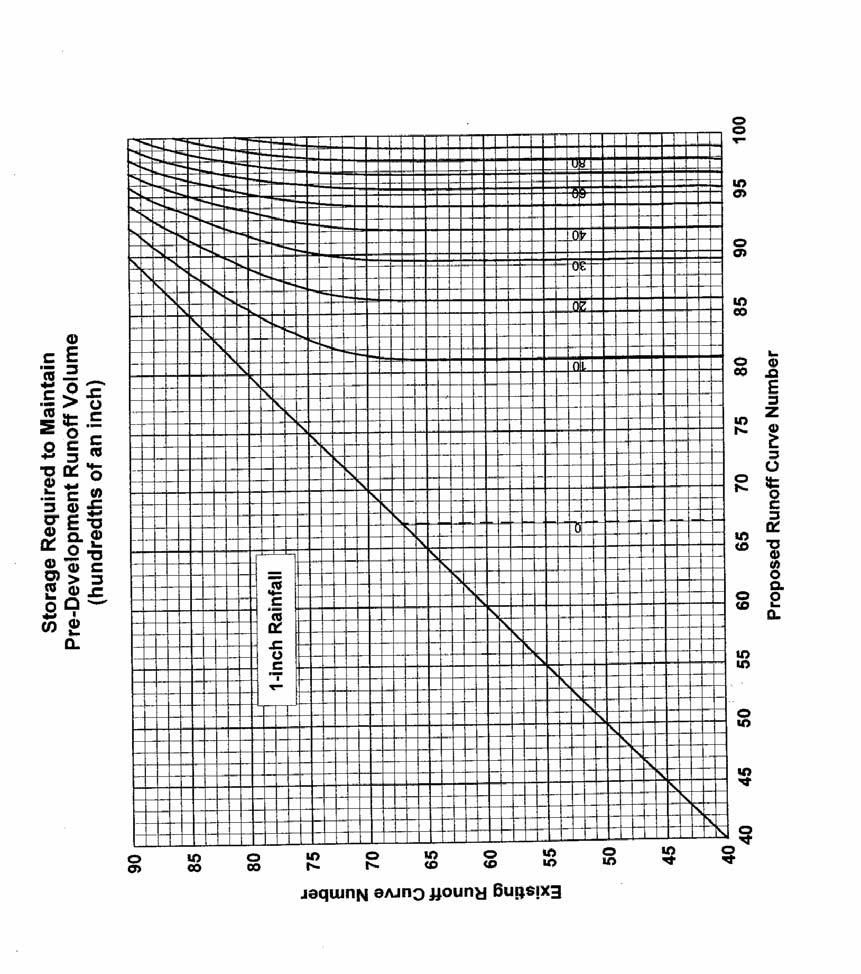
118 A6-34
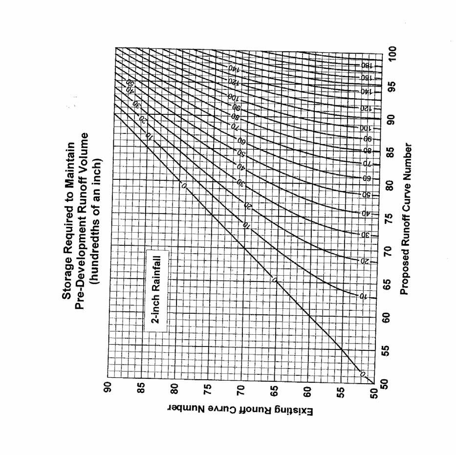
119 A6-35
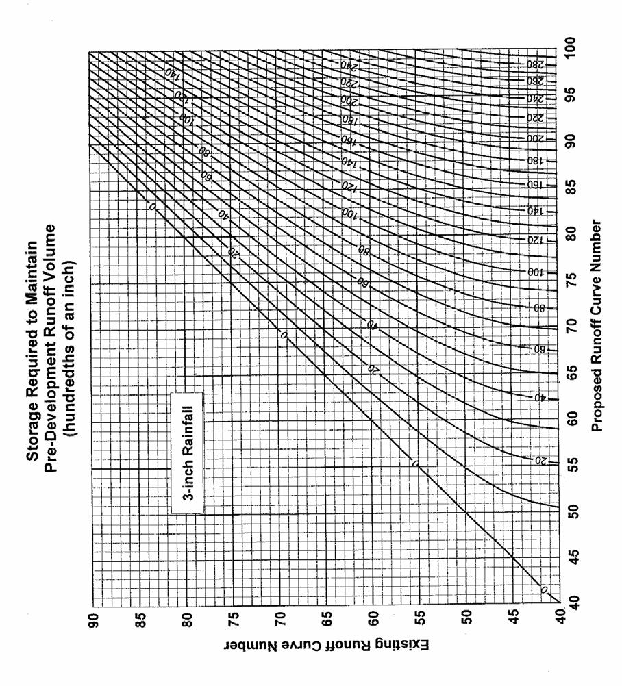
120 A6-36
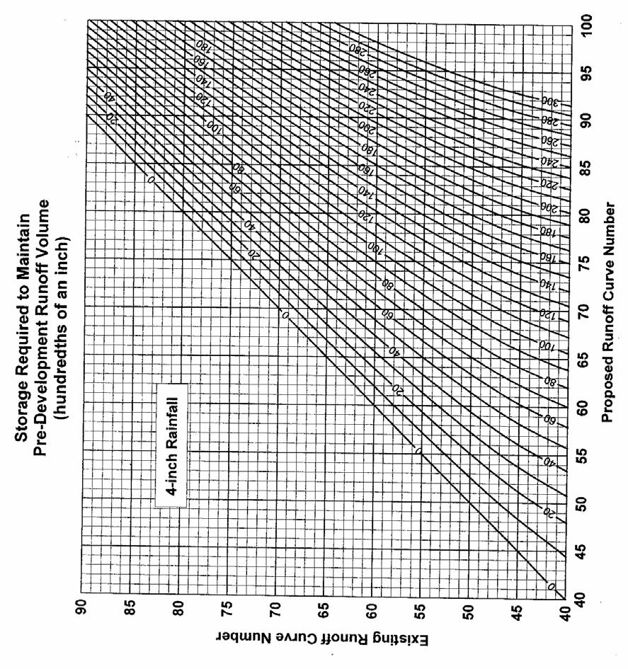
121 A6-37
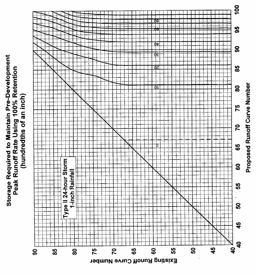
122 A6-38
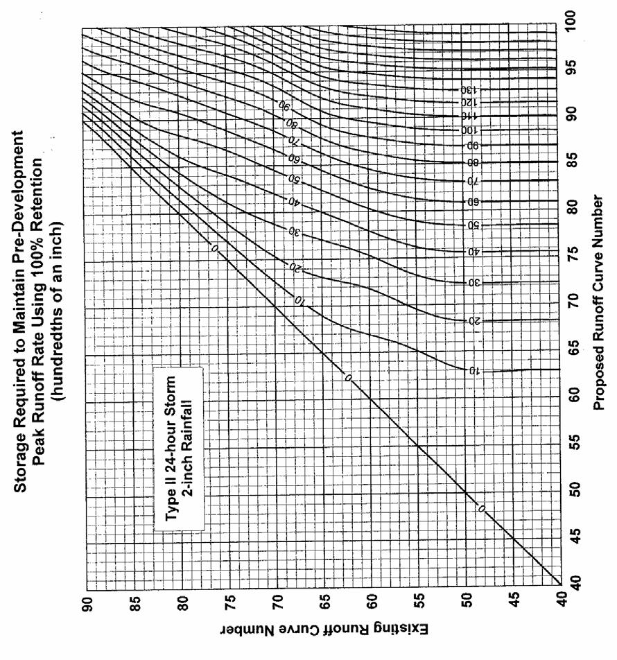
123 A6-39
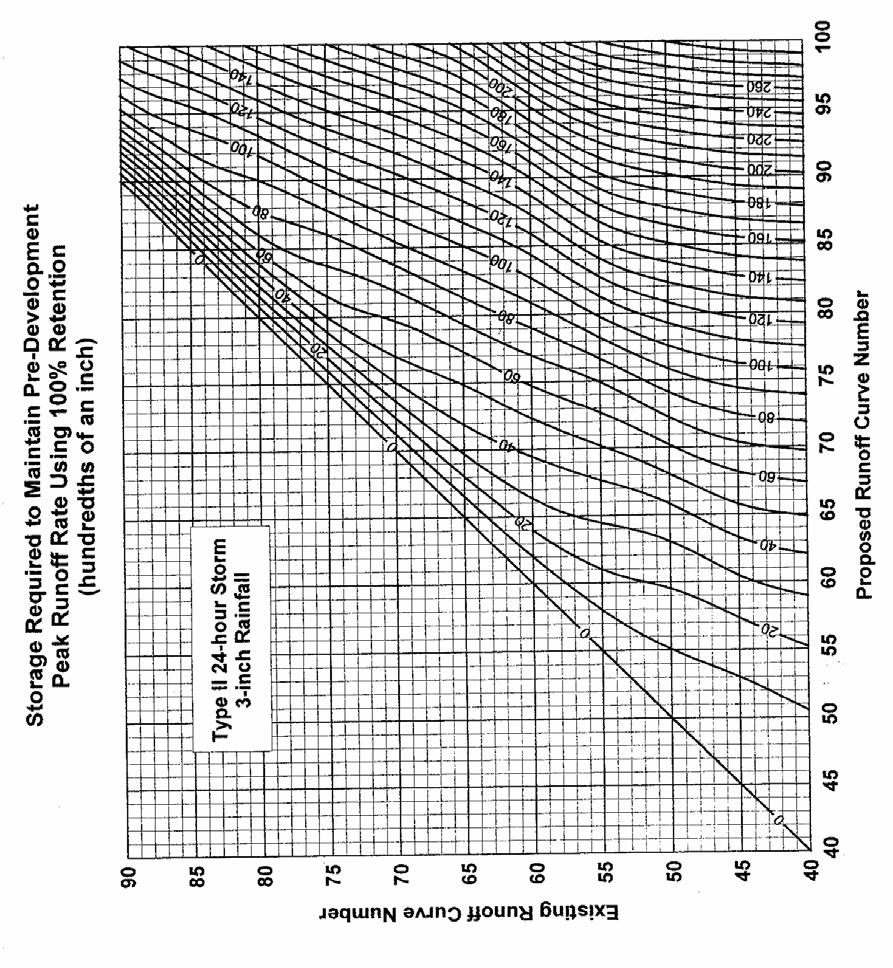
124 A6-40
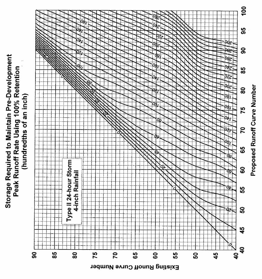
125 A6-41
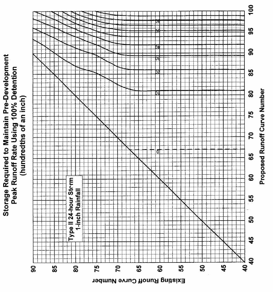
126 A6-42
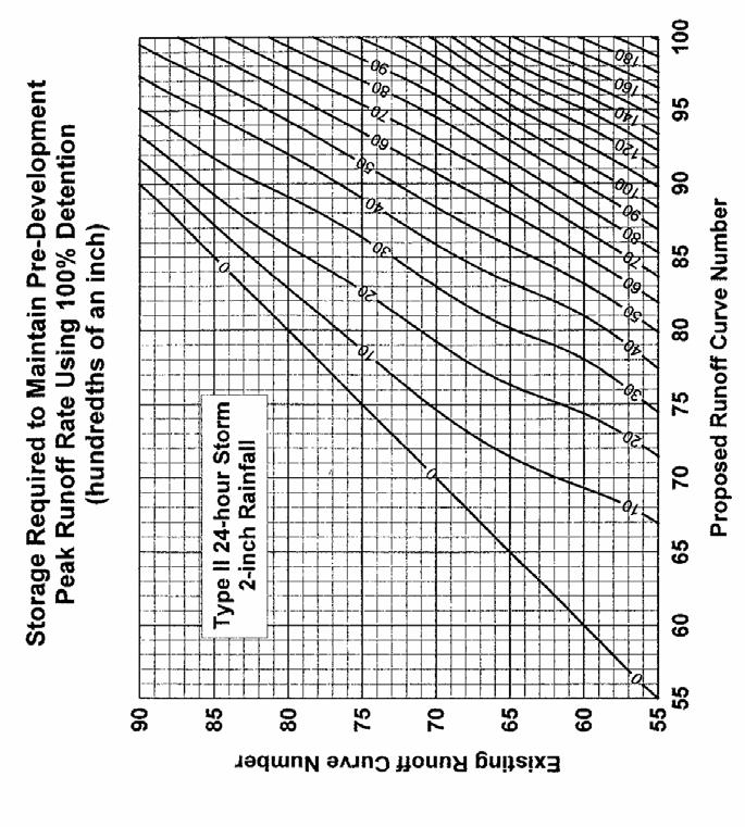
127 A6-43

128 A6-44
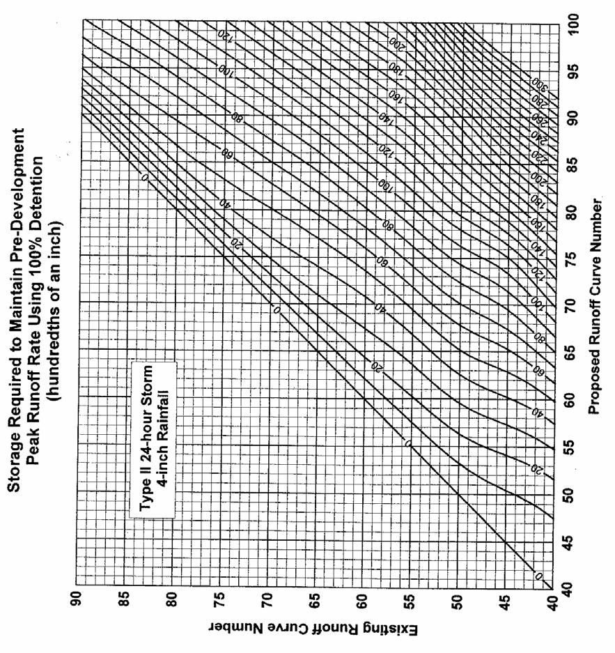
129 A6-45
SECTION 3 DRAINAGE. 3-1 General. 3-2 Drainage Ordinances and Legal Requirements
 SECTION 3 DRAINAGE 3-1 General All Drainage plans for proposed development shall be prepared by a Professional Engineer registered in Virginia, except as noted below. Further, their seal and signature
NEW CASTLE CONSERVATION DISTRICT. through. (Name of Municipality) PLAN REVIEW APPLICATION DRAINAGE, STORMWATER MANAGEMENT, EROSION & SEDIMENT CONTROL
 PLAN REVIEW APPLICATION DRAINAGE, STORMWATER MANAGEMENT, EROSION & SEDIMENT CONTROL") NEW CASTLE CONSERVATION DISTRICT through (Name of Municipality) PLAN REVIEW APPLICATION DRAINAGE, STORMWATER MANAGEMENT, EROSION & SEDIMENT CONTROL Office use only: Received by Municipality: Received by
NEW CASTLE CONSERVATION DISTRICT through (Name of Municipality) PLAN REVIEW APPLICATION DRAINAGE, STORMWATER MANAGEMENT, EROSION & SEDIMENT CONTROL Office use only: Received by Municipality: Received by
Stormwater Local Design Manual For Houston County, Georgia
 Stormwater Local Design Manual For Houston County, Georgia Adopted November 15, 2005 TABLE OF CONTENTS 1. FORWARD... 1 2. GENERAL LEVEL OF SERVICE STANDARDS... 2 2.1. DETENTION REQUIREMENTS... 2 2.1.1.
Construction Inspection Checklists
 III. Construction Inspection Checklists 33 Bioretention - Construction Inspection Checklist Project: Location: Site Status: Date: Time: Inspector: Construction Sequence Satisfactory / Unsatisfactory Comments
MODEL Stormwater Local Design Manual. City of Centerville
 MODEL Stormwater Local Design Manual City of Centerville Adopted December 6, 2005 TABLE OF CONTENTS 1. FORWARD... 1 2. GENERAL LEVEL OF SERVICE STANDARDS... 1 2.1. DETENTION REQUIREMENTS... 1 2.1.1. Discharge
Ordinance No Lot Surface Drainage
 Ordinance No. 35-2008 - Lot Surface Drainage The Township has adopted a new Lot Surface Drainage Ordinance which amends Chapter 170, Article IX, Subdivision and Site Plan Review by adding a new Section
CITY UTILITIES DESIGN STANDARDS MANUAL
 CITY UTILITIES DESIGN STANDARDS MANUAL () September 2017 Page Chapter 1 Acronyms and Definitions 1.01 Purpose 1 1.02 Acronyms 1 1.03 Definitions 3 Chapter 2 Introduction 2.01 Purpose 1 2.02 Applicability
SECTION STORM DRAINAGE DESIGN, GRADING, AND WATER QUALITY TECHNICAL CRITERIA TABLE OF CONTENTS PAGE 402 STORM DRAINAGE DESIGN CRITERIA 400-1
 CITY OF THORNTON Standards and Specifications Revised: October 2012 SECTION 400 - STORM DRAINAGE DESIGN, GRADING, AND WATER QUALITY TECHNICAL CRITERIA TABLE OF CONTENTS PAGE 401 GENERAL PROVISIONS 400-1
3.0 Planning and Submittal Requirements
 October 2003, Revised February 2005 Chapter 3.0, Planning and Submittal Requirements Page 1 3.0 Planning and Submittal Requirements 3.1 Drainage Studies and Drawings The City of Greenwood Village (Village)
CHAPTER 9 STORMWATER MANAGEMENT PLAN REQUIREMENTS
 CHAPTER 9 9.1 INTRODUCTION The Virginia Stormwater Management Program (VSMP) Act and Regulations require that Henrico County adopt a local program to administer the requirements. The requirements are addressed
Chapter 4. Drainage Report and Construction Drawing Submittal Requirements
 4.0 Introduction The requirements presented in this section shall be used to aid the design engineer or applicant in the preparation of drainage reports, drainage studies, and construction drawings for
FIRM NAME DESIGNER: CHECKER: DATE: FPID #: DESCRIPTION: COUNTY: DRAINAGE DESIGN CHECKLIST. Designers Initials. Checkers Initials.
 I. Drainage Report A. Executive Summary - Brief Overview of Project Drainage Design B. Project Description 1. Existing Conditions 2. Proposed Project Conditions 3. Project Justification Narrative - Basin
Chapter 3 Dispersion BMPs
 Chapter 3 Dispersion BMPs 3.1 BMP L611 Concentrated Flow Dispersion 3.1.1 Purpose and Definition Dispersion of concentrated flows from driveways or other pavement through a vegetated pervious area attenuates
Environmental Management Chapter ALABAMA DEPARTMENT OF ENVIRONMENTAL MANAGEMENT WATER DIVISION - WATER QUALITY PROGRAM ADMINISTRATIVE CODE
 Environmental Management Chapter 335-6-9 ALABAMA DEPARTMENT OF ENVIRONMENTAL MANAGEMENT WATER DIVISION - WATER QUALITY PROGRAM ADMINISTRATIVE CODE CHAPTER 335-6-9 SURFACE MINING RULES TABLE OF CONTENTS
Erosion & Sedimentation Control Policy
 Issue Date 10/22/2010 Page 1 of 8 Erosion & Sedimentation Control Policy Introduction: Soil erosion is the removal of soil by water, wind, ice or gravity and sediment deposition occurs when the rate of
Richland County Department of Public Works Engineering (Land Development) Division
 Division") Richland County Department of Public Works Engineering (Land Development) Division Commercial Projects What is a Commercial Project? Projects that are not related to residential single family homes and/or
Richland County Department of Public Works Engineering (Land Development) Division Commercial Projects What is a Commercial Project? Projects that are not related to residential single family homes and/or
City of Redwood City Stormwater Pollution Prevention Program. Drainage Guidelines for Residential Development
 City of Redwood City Stormwater Pollution Prevention Program Drainage Guidelines for Residential Development General Requirements A. Plot & Finished Grading Plan must be submitted with Building Permit
Lyon Creek Cedar Way Stormwater Detention Dam Operation and Maintenance Manual
 Lyon Creek Cedar Way Stormwater Detention Dam Operation and Maintenance Manual Prepared by: Mike Shaw Stormwater Program Manager City of Mountlake Terrace January 2010 Section I General Information This
E. STORMWATER MANAGEMENT
 E. STORMWATER MANAGEMENT 1. Existing Conditions The Project Site is located within the Lower Hudson Watershed. According to the New York State Department of Environmental Conservation (NYSDEC), Lower Hudson
iswm TM Criteria Manual City of Azle Section 14 City of Azle Subdivision Ordinance DRAFT-June Chapter 1
 City of Azle Section 14 City of Azle Subdivision Ordinance DRAFT-June 2010... Chapter 1 i CITY OF AZLE iswm CRITERIA MANUAL FOR SITE DEVELOPMENT AND CONSTRUCTION Incorporating the Regional NCTCOG Integrated
Stormwater Management Criteria
 FOR OFFICE USE ONLY Stormwater Management Criteria Form #PWU005 (rev. 11/16) Approving Agency Performance Standards Applicability for Control of Stormwater Pollution Applicability for Control of Peak Runoff
TEMPORARY SEDIMENT TRAP CODE
 ILLINOIS URBAN MANUAL PRACTICE STANDARD TEMPORARY SEDIMENT TRAP CODE 960 Source: DEFINITION A small temporary stormwater storage structure designed to trap sediment. PURPOSE The purpose of this practice
SECTION 4 SURFACE WATER MANAGEMENT DESIGN AND CONSTRUCTION REQUIREMENTS
 SECTION 4 SURFACE WATER MANAGEMENT DESIGN AND CONSTRUCTION REQUIREMENTS Page 4-1 INTRODUCTION 4-3 4-1.01 Applicability of VMCs 14.24, 14.25, 14.26 4-4 4-1.02 Minimum Requirements - Projects Below Threshold
Municipal Stormwater Ordinances Summary Table
 APPENDIX F Municipal Ordinances Summary Table Municipality Abington Bryn Athyn Borough Hatboro Borough Ordinance, SALDO Runoff equals pre post Erosion Sediment Control Water Quality Requirements Any which
16.0 Water Quality Management Criteria for Developed Land
 October 2003, Revised February 2005 Criteria for Developed Land Page 1 16.1 Introduction 16.0 Water Quality Management Criteria for Developed Land Stormwater quality control is an integral part of any
ARTICLE V: STORMWATER MANAGEMENT AND DRAINAGE SYSTEMS
 ARTICLE V: STORMWATER MANAGEMENT AND DRAINAGE SYSTEMS Section 501: Purpose An adequate drainage system including necessary ditches, pipes, culverts, drains, inlets, bridges, detention ponds, etc. shall
Project Drainage Report
 Design Manual Chapter 2 - Stormwater 2A - General Information 2A-4 Project Drainage Report A. Purpose The purpose of the project drainage report is to identify and propose specific solutions to stormwater
DESIGN BULLETIN #16/2003 (Revised July 2007) Drainage Guidelines for Highways Under Provincial Jurisdiction in Urban Areas.
 Drainage Guidelines for Highways Under Provincial Jurisdiction in Urban Areas.") Drainage Guidelines for Highways Under Provincial Jurisdiction in Urban Areas. July 2007 Update to Design Bulletin #16/2003: Added under Design Criteria Culverts of 600mm diameter are commonly used to
Drainage Guidelines for Highways Under Provincial Jurisdiction in Urban Areas. July 2007 Update to Design Bulletin #16/2003: Added under Design Criteria Culverts of 600mm diameter are commonly used to
Appendix J: Storm Conveyance Design Parameters
 Appendix J: Storm Conveyance Design Parameters Drain Commissioner 39 February 2005 STORM DRAINAGE DESIGN CRITERIA A. STORM SEWERS 1. The required discharge capacity shall be determined by the Rational
Chapter 11 Culverts and Bridges
 Chapter 11 Culverts and Bridges Contents 1.0 Introduction... 1 2.0 General Design... 1 2.1 Design Criteria... 1 2.2 Design Flows... 1 2.3 Permitting and Regulations... 1 2.4 Aesthetics and Safety... 2
Chapter 21 Stormwater Management Bylaw
 Chapter 21 Stormwater Management Bylaw SECTION 1. PURPOSE The purpose of this Bylaw is to: implement the requirements of the National Pollutant Discharge Elimination System (NPDES) General Permit for Storm
ENGINEERING CHECKLIST SEDIMENT & STORMWATER MANAGEMENT BASIN CONSTRUCTION
 NEW CASTLE COUNTY DEPARTMENT OF LAND USE ENGINEERING CHECKLIST SEDIMENT & STORMWATER MANAGEMENT BASIN CONSTRUCTION For Permanent Structures, pursuant to Delaware Pond Code 378 and Delaware Sediment and
STORMWATER DEVELOPMENT GUIDELINES
 1600 Battle Creek Road, Morrow, Georgia 30260 STORMWATER DEVELOPMENT GUIDELINES Second Edition November 2006 Program Management & Engineering Department Office: (770) 961-2130 Fax: (770) 960-5229 STORMWATER
Stormwater Management Studies PDS Engineering Services Division ES Policy # 3-01
 Stormwater Management Studies PDS Engineering Services Division Revised Date: 2/28/08 INTRODUCTION The City of Overland Park requires submission of a stormwater management study as part of the development
ARTICLE A. POST-DEVELOPMENT STORMWATER MANAGEMENT FOR NEW DEVELOPMENT AND REDEVELOPMENT
 CHAPTER 11. STORMWATER MANAGEMENT ARTICLE A. POST-DEVELOPMENT STORMWATER MANAGEMENT FOR NEW DEVELOPMENT AND REDEVELOPMENT DIVISION 1. GENERALLY Sec. 10-11001. FINDINGS It is hereby determined that: (1)
Plan Name Plan No. Submitting Firm Contact Engineer. Review Date ESI Team ENGINEERS AND SURVEYORS INSTITUTE PEER REVIEW CHECKLIST CITY OF ALEXANDRIA
 EROSION AND SEDIMENT CONTROL CHECKLIST (E&S) VIRGINIA EROSION AND SEDIMENT CONTROL HANDBOOK (1 of 2) Item # Description OK NO N/A 1 Limits of clearing and grading match on all appropriate sheets 2 Construction
At least 2 feet above the seasonal high water table Overflow path or structure provided
 General Conditions Map of proposed subwatershed to each subbasin, including total area and CN Design Flow or Design Volume to each STF, as appropriate Operation and Maintenance instructions for each STF
Infiltration Guidelines
 Appendix E Infiltration Guidelines As a stormwater management method, infiltration means retaining or detaining water within soils to reduce runoff. Infiltration can be a cost-effective method to manage
STORMWATER RUNOFF AND WATER QUALITY IMPACT REVIEW
 SUBCHAPTER 8 STORMWATER RUNOFF AND WATER QUALITY IMPACT REVIEW 7:45-8.1 Purpose and scope of review Except for those projects expressly exempted by this chapter or waived by the Commission, the Commission
STORMWATER AND EROSION CONTROL PERMIT
 STORMWATER MANAGEMENT AND EROSION CONTROL PERMIT INSTRUCTIONS AND INFORMATION Any project that involves the disturbance of ANY quantity of land requires the applicant to receive approval for the project
SECTION TRENCHING & BACKFILLING
 SECTION 02225 - TRENCHING & BACKFILLING 1.0 GENERAL 1.1 Work included in this Section includes trenching and backfilling for underground pipelines and related structures only. 1.2 Reference Specifications
INFLOW DESIGN FLOOD CONTROL SYSTEM PLAN 40 C.F.R. PART PLANT YATES ASH POND 3 (AP-3) GEORGIA POWER COMPANY
 GEORGIA POWER COMPANY") INFLOW DESIGN FLOOD CONTROL SYSTEM PLAN 40 C.F.R. PART 257.82 PLANT YATES ASH POND 3 (AP-3) GEORGIA POWER COMPANY EPA s Disposal of Coal Combustion Residuals from Electric Utilities Final Rule (40 C.F.R.
INFLOW DESIGN FLOOD CONTROL SYSTEM PLAN 40 C.F.R. PART 257.82 PLANT YATES ASH POND 3 (AP-3) GEORGIA POWER COMPANY EPA s Disposal of Coal Combustion Residuals from Electric Utilities Final Rule (40 C.F.R.
4.8. Subsurface Infiltration
 4.8. Subsurface Infiltration Subsurface infiltration systems are designed to provide temporary below grade storage infiltration of storm water as it infiltrates into the ground. Dry wells, infiltration
Understanding Stormwater Pollution Prevention Plans (SWPPPs) (SWPPPS)
 (SWPPPS)") Understanding Stormwater Pollution Prevention Plans (SWPPPs) (SWPPPS) Definitions SWPPP: Storm Water Pollution Prevention Plan BMP: Best Management Practice(s) to control pollution IDNR: Iowa Department
Understanding Stormwater Pollution Prevention Plans (SWPPPs) (SWPPPS) Definitions SWPPP: Storm Water Pollution Prevention Plan BMP: Best Management Practice(s) to control pollution IDNR: Iowa Department
Sediment Basin. Fe= (Depends on soil type)
") 3.9 Sediment Control Description: A sediment basin is an embankment with a controlled outlet that detains stormwater runoff, resulting in the settling of suspended sediment. The basin provides treatment
3.9 Sediment Control Description: A sediment basin is an embankment with a controlled outlet that detains stormwater runoff, resulting in the settling of suspended sediment. The basin provides treatment
Hydrology Study. Ascension Heights Subdivision Ascension Drive at Bel Aire Road San Mateo, California (Unincorporated)
") Hydrology Study Ascension Heights Subdivision Ascension Drive at Bel Aire Road San Mateo, California (Unincorporated) Prepared for San Mateo Real Estate & Construction March 9, 21 Rev. 1 11-8-211 Rev.
Hydrology Study Ascension Heights Subdivision Ascension Drive at Bel Aire Road San Mateo, California (Unincorporated) Prepared for San Mateo Real Estate & Construction March 9, 21 Rev. 1 11-8-211 Rev.
S.O.P. No. HMD
 Page: 1 of 9 PURPOSE: To establish (SOP) for submission requirements, review process and approval of applications for Non-vehicular Access Permits for the purpose of connection or discharge to any MassDOT
Chatham Park Stormwater Manual
 Chatham Park Stormwater Manual Table of Contents A. Introduction... 2 B. Calculation Methods... 2 C. BMP Design Standards... 3 D. Compliance Points... 3 E. Critical Environmental Resources... 3 F. Submittal
Storm. Section. B. General Design and Drawing Standards Design
 Section Storm 5 General Plans for the existing stormwater system are maintained in digital and printed form by the City. Copies may be obtained from the Utility Division of the Public Works Department.
STORM AND SURFACE WATER 4-1 GENERAL...4-1
 SECTION 4 STORM AND SURFACE WATER SECTION DESCRIPTION PAGE 4-1 GENERAL...4-1 4-2 STORM DRAINAGE CONVEYANCE SYSTEM DESIGN CRITERIA...4-1 4-2.1 Overview...4-1 4-2.2 Design Flow and Route Requirements...4-2
CHECKLIST FOR STREETS, INLETS, AND STORM SEWER DESIGN
 CHECKLIST FOR STREETS, INLETS, I. STREET CLASSIFICATION AND DESIGN CRITERIA A. Determine drainage classification for the roadway section using Table 7-1 or Table 7-2. B. Determine the allowable flow depth
PART 3 - STANDARDS FOR SEWERAGE FACILITIES DESIGN OF STORM SEWERS
 PART 3 - STANDARDS FOR SEWERAGE FACILITIES 3.3 - DESIGN OF STORM SEWERS 3.301 Design of Storm Sewers A. General Information B. Investigations and Surveys C. Special Projects 3.302 Design Criteria for Storm
BMP 6.4.4: Infiltration Trench
 BMP 6.4.4: Infiltration Trench An Infiltration Trench is a leaky pipe in a stone filled trench with a level bottom. An Infiltration Trench may be used as part of a larger storm sewer system, such as a
Chapter 6. Hydrology. 6.0 Introduction. 6.1 Design Rainfall
 6.0 Introduction This chapter summarizes methodology for determining rainfall and runoff information for the design of stormwater management facilities in the City. The methodology is based on the procedures
COON CREEK WATERSHED DISTRICT PERMIT REVIEW. Spring Lake Park Schools Westwood Middle School st Avenue NE, Spring Lake Park, MN 55432
 PAN 16-112, Westwood Middle School, Page 1 of 6 COON CREEK WATERSHED DISTRICT PERMIT REVIEW MEETING DATE: August 22, 2016 AGENDA NUMBER: 10 FILE NUMBER: 16-112 ITEM: Westwood Middle School RECOMMENDATION:
4.8. Subsurface Infiltration
 4.8. Subsurface Infiltration Subsurface infiltration systems are designed to provide temporary below grade storage infiltration of stormwater as it infiltrates into the ground. Dry wells, infiltration
APPLICATION FOR PUBLIC INFRASTRUCTURE PERMIT
 APPLICATION FOR PUBLIC INFRASTRUCTURE PERMIT Engineering Division 550 Landa Street New Braunfels, Texas 78130 (830) 221-4020 1. Subdivision Plat Name: Location Description/ Nearest Intersection: Acreage:
MICHIGAN DESIGN MANUAL ROAD DESIGN CHAPTER 4 INDEX DRAINAGE
 CHAPTER 4 INDEX DRAINAGE Supplement to Chapter 4 4.01 GENERAL INFORMATION 4.01.01 References 4.01.03 General Procedures 4.02 STORM SEWER DESIGN 4.02.15 Sewer Bulkheads 4.02.18 Storm Sewers Under Structures
Article 20: Erosion Control and Stormwater Management
 Article 20: Erosion Control and Stormwater Management Section 360: Purpose, Scope of Authority, Performance Guarantee and Approvals A. Purpose. The purpose of this document is to set forth minimum requirements
Highway Drainage 1- Storm Frequency and Runoff 1.1- Runoff Determination
 Highway Drainage Proper drainage is a very important consideration in design of a highway. Inadequate drainage facilities can lead to premature deterioration of the highway and the development of adverse
SACHSE EROSION CONTROL GUIDELINES
 SACHSE EROSION CONTROL GUIDELINES Section I. Definitions The following words, terms, and phrases, when used in this guideline, shall have the meanings ascribed to them in this Section, except where the
Project Name: Add a unique name that appropriately identifies the submission
 PTAPP Online Municipal Tracking Tool Instructions Project Name: Add a unique name that appropriately identifies the submission Municipal Project: Check this box if the project is part of municipal efforts
V. DRAINAGE IMPROVEMENTS
 V. DRAINAGE IMPROVEMENTS 5.1 Formulation of Drainage Improvements As indicated in Chapter 4, following the completion of the hydrologic analysis associated with future land use conditions, drainage improvements
CITY OF ASTORIA PUBLIC WORKS ENGINEERING DIVISION ENGINEERING DESIGN STANDARDS FOR IN-FILL DEVELOPMENT
 CITY OF ASTORIA PUBLIC WORKS ENGINEERING DIVISION ENGINEERING DESIGN STANDARDS FOR IN-FILL DEVELOPMENT Adopted by City Council: May 21, 2007 X:\General Eng\DESIGN STANDARDS\Engineering Design Standards
GWINNETT COUNTY STORM SEWER PIPE STANDARDS
 1.0 Standard Specifications GWINNETT COUNTY STORM SEWER PIPE STANDARDS 1.1 Unless otherwise specifically set forth herein or in the Gwinnett County Standard Drawings, all of the materials, methods of the
CRITERIA FOR STORMWATER DESIGN
 ..CHAPTER.. CRITERIA FOR STORMWATER DESIGN 2.1 Integrated Site Design Approach 2.1.1 Introduction This chapter represents the requirements, policies and other guidance for stormwater management design
CHAPTER 7 - INFRASTRUCTURE INSPECTION AND ACCEPTANCE... 2
 CHAPTER 7 - INFRASTRUCTURE INSPECTION AND ACCEPTANCE... 2 7.1. GENERAL.... 2 7.1.1. Inspection Restriction Dates.... 2 7.1.2. Complete Improvements.... 2 7.1.3. Public Improvements.... 2 7.1.4. Warranty
INFLOW DESIGN FLOOD CONTROL SYSTEM PLAN PLANT GREENE COUNTY ASH POND ALABMA POWER COMPANY
 INFLOW DESIGN FLOOD CONTROL SYSTEM PLAN PLANT GREENE COUNTY ASH POND ALABMA POWER COMPANY Section 257.82 of EPA s regulations requires the owner or operator of an existing or new CCR surface impoundment
Appendix G Preliminary Hydrology Study
 Appendix G Preliminary Hydrology Study Preliminary Hydrology Study VESTING TTM 72608 Long Beach, CA Prepared for: The Long Beach Project, LLC 888 San Clemente, Suite 100 New Port Beach, CA May 28, 2014
CHAPTER 8 EROSION AND SEDIMENT CONTROL PLAN REQUIREMENTS
 CHAPTER 8 EROSION AND SEDIMENT CONTROL PLAN REQUIREMENTS 8.1 INTRODUCTION To minimize the detrimental effects of erosion and sedimentation, Henrico County requires that those individuals responsible for
APPENDIX A EARTHEN EMBANKMENT. VERSION 1.0 March 1, 2011
 APPENDIX A EARTHEN EMBANKMENT VERSION 1.0 March 1, 2011 SECTION A-1: DESCRIPTION OF PRACTICE An earthen embankment is a raised impounding structure made from compacted soil. The embankment is the feature
HYDROLOGIC CONSIDERATIONS. 22 nd Annual Nonpoint Source Pollution Conference Saratoga Springs, NY
 LOW IMPACT DEVELOPMENT HYDROLOGIC CONSIDERATIONS 22 nd Annual Nonpoint Source Pollution Conference Saratoga Springs, NY May 18, 2011 PRESENTATION AGENDA Introduction Definitions Discuss Impacts to Hydrologic
Contact the Jurisdictional Engineer for materials allowed by each jurisdiction.
 Design Manual Chapter 3 - Sanitary Sewers 3C - Facility Design 3C-1 Facility Design A. Capacity of Pipe Pipe sizes 15 inches and smaller should carry the peak flow at a depth of no more than 0.67 of the
Water Quality: 1.0 Water Quality Protection Volume and Peak Flow 2.0 Construction SWP3 Guidelines and Form
 : 1.0 Protection Volume and Peak Flow 2.0 and Form Table of Contents 1.0 Protection Volume and Peak Flow...WQ-1 1.1 Introduction...WQ-1 1.2 Protection Volume Calculation...WQ-1 1.3 Protection Volume Reduction
DRAINAGE & DESIGN OF DRAINAGE SYSTEM
 Drainage on Highways DRAINAGE & DESIGN OF DRAINAGE SYSTEM P. R.D. Fernando Chartered Engineer B.Sc.(Hons), M.Eng. C.Eng., MIE(SL) Drainage Requirement of Highway Drainage System Introduction Drainage means
Chapter 7. Street Drainage. 7.0 Introduction. 7.1 Function of Streets in the Drainage System. 7.2 Street Classification
 7. Introduction This chapter summarizes methods to evaluate runoff conveyance in various street cross sections and curb types in the Town of Castle Rock and identifies acceptable upper limits of street
Boise City Public Works General Drainage Plan Review Requirements Checklist
 Boise City Public Works General Drainage Plan Review Requirements Checklist Development Name Bldg. Permit # Drainage Reviewer Site Address Initial Review Date ODI Number Designer Company Name Treated Acres
Standards for Soil Erosion and Sediment Control in New Jersey May 2012 STANDARD FOR SLOPE PROTECTION STRUCTURES. Definition
 STANDARD FOR SLOPE PROTECTION STRUCTURES Definition Structures to safely conduct surface runoff from the top of a slope to the bottom of the slope. Purpose The purpose of this practice is to convey storm
Constructed Wetland Pond T-8
 Constructed Wetland Pond T-8 Description A constructed wetlands pond is a shallow retention pond designed to permit the growth of wetland plants such as rushes, willows, and cattails. Constructed wetlands
PRELIMINARY DRAINAGE REPORT NEWCASTLE FIRE STATION OLD STATE HIGHWAY
 PRELIMINARY DRAINAGE REPORT FOR THE NEWCASTLE FIRE STATION OLD STATE HIGHWAY PREPARED FOR THE NEWCASTLE FIRE PROTECTION DISTRICT JULY 2014 BY ROSEVILLE DESIGN GROUP, INC. ROSEVILLE DESIGN GROUP, Inc Established
CHAPTER 6 ADDITIONAL STANDARDS APPLYING TO SHORELAND AREAS AND PUBLIC WATERS
 CHAPTER 6 ADDITIONAL STANDARDS APPLYING TO SHORELAND AREAS AND PUBLIC WATERS Section 1 Intent. 49 Section 2 Floodplain Requirements 49 Section 3 Water-Oriented Accessory Structures 50 Section 4 Stairways,
SECTION 2 DESIGN CRITERIA
 SECTION 2 DESIGN CRITERIA 2.1 GENERAL The following criteria will be utilized by the District Engineer, and/or a consultant, in the review of development plans for recommending approval of the proposed
Stormwater Drainage Criteria Manual. City Of Clearwater Engineering Department Effective July 1, 2015
 Stormwater Drainage Criteria Manual City Of Clearwater Engineering Department Effective July 1, 2015 Engineering Department STORMWATER DRAINAGE CRITERIA MANUAL Table of Contents STORMWATER DRAINAGE CRITERIA
6.0 Runoff. 6.1 Introduction. 6.2 Flood Control Design Runoff
 October 2003, Revised February 2005 Chapter 6.0, Runoff Page 1 6.1 Introduction 6.0 Runoff The timing, peak rates of discharge, and volume of stormwater runoff are the primary considerations in the design
Chapter 2 ADMINISTRATIVE PROCEDURES
 Chapter 2 2.01 General 2.01.1 Application of Chapter 2.01.2 Fees 2.02 Pre-Development Site Certification and Assessment 2.03 Construction Permits 2.03.1 Site Development Permit 2.03.2 Development Permits
Determination of Design Infiltration Rates for the Sizing of Infiltration based Green Infrastructure Facilities
 Determination of Design Infiltration Rates for the Sizing of Infiltration based Green Infrastructure Facilities 1 Introduction This document, developed by the San Francisco Public Utilities Commission
Volume 2, Chapter 10 - Storage
 Volume 2, Chapter 10 - Storage Users Guidance: If a UDFCD Section number in this chapter is skipped: It was adopted as is; please refer to that Section in the corresponding UDFCD Manual, Volume, Chapter
SUBSURFACE INFILTRATION SYSTEM DESCRIPTION. Alternative Names: Sump, Drywell, Infiltration Trench, Infiltration Galleries, Leach Fields
 4.1-d SUBSURFACE INFILTRATION SYSTEM Alternative Names: Sump, Drywell, Infiltration Trench, Infiltration Galleries, Leach Fields BMP DESIGN APPROACH Pollutant Source Control Hydrologic Source Control Stormwater
GRASS-LINED CHANNEL (acre) CODE 840
 CODE 840") NATURAL RESOURCES CONSERVATION SERVICE ILLINOIS URBAN MANUAL PRACTICE STANDARD GRASS-LINED CHANNEL (acre) CODE 840 (Source: NC Erosion and Sediment Control Field Manual) DEFINITION A natural or constructed
NATURAL RESOURCES CONSERVATION SERVICE ILLINOIS URBAN MANUAL PRACTICE STANDARD GRASS-LINED CHANNEL (acre) CODE 840 (Source: NC Erosion and Sediment Control Field Manual) DEFINITION A natural or constructed
SPECIFICATIONS FOR STREET CONSTRUCTION WITHIN THE TOWN OF PLAINVILLE
 SPECIFICATIONS FOR STREET CONSTRUCTION WITHIN THE TOWN OF PLAINVILLE BE IT ORDAINED by the Town Council of the Town of Plainville: SECTION 1. SUBDIVISIONS. All subdivisions hereinafter developed within
Preliminary Drainage Analysis
 Preliminary Drainage Analysis Tanimura and Antle Employee Housing Town of Spreckels County of Monterey, California LIB150205 May 29, 2015 Prepared For: Tanimura and Antle Produce Prepared By: 9699 Blue
NORTH CAROLINA DEPARTMENT OF HEALTH AND HUMAN SERVICES DIVISION OF PUBLIC HEALTH ENVIRONMENTAL HEALTH SECTION ON-SITE WATER PROTECTION BRANCH
 NORTH CAROLINA DEPARTMENT OF HEALTH AND HUMAN SERVICES DIVISION OF PUBLIC HEALTH ENVIRONMENTAL HEALTH SECTION ON-SITE WATER PROTECTION BRANCH INNOVATIVE WASTEWATER SYSTEM APPROVAL INNOVATIVE WASTEWATER
GRADING & DRAINAGE PERMIT SOIL EROSION AND SEDIMENTATION CONTROL PERMIT PROGRAM OVERVIEW
 GRADING & DRAINAGE PERMIT SOIL EROSION AND SEDIMENTATION CONTROL PERMIT PROGRAM OVERVIEW Chapter 8 Building and Building Regulations, Article XIII Grading and Drainage and Article XV Soil Erosion and Sedimentation
INFLOW DESIGN FLOOD CONTROL SYSTEM PLAN PLANT BARRY ASH POND ALABAMA POWER COMPANY
 INFLOW DESIGN FLOOD CONTROL SYSTEM PLAN PLANT BARRY ASH POND ALABAMA POWER COMPANY Section 257.82 of EPA s regulations requires the owner or operator of an existing or new CCR surface impoundment or any
City of Tulsa. Stormwater Design Criteria Manual
 City of Tulsa Stormwater Design Criteria Manual 2014 Table of Contents Chapter 100 EXECUTIVE SUMMARY... 101 101 INTRODUCTION... 101 101.1 Manual Organization... 101 101.2 Manual Contents... 101 101.2.1
Best Management Practice Fact Sheet 10: Dry Swale
 Publication 426-129 Best Management Practice Fact Sheet 10: Dry Swale David J. Sample, Assistant Professor and Extension Specialist, Biological Systems Engineering, Virginia Tech Lia Doumar, Undergraduate
TECHNICAL CONTENT PROPOSED STEEP SLOPE REGULATION
 1 TECHNICAL CONTENT PROPOSED STEEP SLOPE REGULATION Draft 2/08/10 (Revised 02-14-11,Revised 02-21-11, Revised 03-03-11, Revised 04-19-11, Revised 04-20-11, Revised 05-05-11, Revised 05-09-11). DEFINITIONS
PERMEABLE INTERLOCKING PAVERS
 PERMEABLE INTERLOCKING PAVERS PART 1 - GENERAL 1.01 SECTION INCLUDES A. Subgrade Preparation B. Placement of Storage Aggregate C. Placement of Filter Aggregate D. Placement of Bedding Course E. Placement
Diversion Dikes. Fe=0.95
 2.2 Diversion Dike Erosion Control Description: A diversion dike is a compacted soil mound, which redirects runoff to a desired location. The dike is typically stabilized with natural grass for low velocities
Installation and Maintenance of Erosion Control BMPs
 Installation and Maintenance of Erosion Control BMPs Or Common BMPs Applications Specifications Installation Problems Maintenance Utility Design Professionals Clarifications, proactive problem solving