INFILTRATION FACILITY MODELING
|
|
|
- Franklin Jones
- 6 years ago
- Views:
Transcription
1 INFILTRATION FACILITY MODELING Clear Creek Solutions, Inc., 2010 Infiltration is good. Infiltration returns the runoff to the ground, allowing it to slowly recharge the aquifer and the nearest stream. The ability to infiltrate runoff into the ground is included in most of the WWHM4 conveyance and storage elements. There are two types of infiltration facilities: those that allow full infiltration and those that provide partial infiltration. With full infiltration there is no surface discharge; all of the water goes into the underlying soil. Partial infiltration has both surface and subsurface discharge. The key to making infiltration work is having the right soils. Infiltration on the poorly draining soils is difficult because of their low infiltration rates. However, there are high infiltration soils (NRCS Type A and B soils) that are excellent for the use of infiltration facilities. Infiltration of runoff is a recommended stormwater solution if certain conditions are met. These conditions include: a soils report, testing, groundwater protection, pre-settling, and appropriate construction techniques. There are times and places where too high infiltration rates, high groundwater tables, and groundwater mounding all can be problems and may make infiltration a poor choice for stormwater control. For these and other reasons it is important to first consult with the local permitting municipality to make sure that infiltration is allowed and that all of the standards and regulations are known. For our project example we are going to size an infiltration facility first for full (100%) infiltration and then for partial (less than 100%) infiltration. We will model a 10-acre site in Thurston County, Washington, near the city of Olympia. The first thing that we will do is to locate our project on the project map. 1

2 Our project site is located near the Olympia Airport in central Thurston County, Washington. We click on the map to select the project location. Based on our project location WWHM4 selects the appropriate precipitation record and precipitation multiplication factor. We then have the option to fill in the Site Information boxes. 2

3 Our predeveloped condition is 8 acres of forest on A/B soil on a flat slope and 2 acres of forest on C soil on a flat slope. 3
 set aside for the infiltration facility. All of the development is on a flat slope (0-5%). The WWHM4 trapezoidal pond element will be used to represent the infiltration facility.")
4 Our proposed development consists of 2 acres of roofs, 3 acres of roads, 1 acre of sidewalks, 1 acre of driveways, 2 acres of lawn on A/B soils, 0.75 acres of lawn on C soils, and a quarter-acre (0.25) set aside for the infiltration facility. All of the development is on a flat slope (0-5%). The WWHM4 trapezoidal pond element will be used to represent the infiltration facility. We need to spend a minute to discuss how the infiltration pond surface area should be handled. We have two options: 1. We represent the pond surface area in the land use basin element as impervious area (as was done above). WWHM4 (and HSPF) then models the surface area as an impervious surface and computes the appropriate impervious surface runoff as input to the pond storage volume. For stormwater projects in the 19 Western Washington counties the Washington State Department of Ecology has decided to require that this is the appropriate option to use in this situation. 2. We do not represent the pond surface area in the land use basin element, but instead rain directly on and evaporate directly from the pond surface area in the pond element. For stormwater projects in Alameda, Santa Clara, and San Mateo counties in the San Francisco Bay Area (California) the county stormwater programs have decided that this is the appropriate option to use in this situation. 4
5 Technically, Option 2 is the most accurate way to model the infiltration pond surface area. However, because this project is in the Western Washington county of Thurston we will use Option 1 and include the pond surface area in the land use basin element area. The next step is to size the infiltration pond. If we are sizing a partial infiltration pond (we will do that after we first size a full infiltration pond) we can use AutoPond, but AutoPond doesn t work when there is no surface discharge from the pond with which to compute the flow durations values. Therefore, sizing a full infiltration pond requires a different process. 5
6 When we change Infiltration from NO to YES we have a new set of infiltration-related input to provide. 6

7 We enter the measured infiltration rate (inches per hour) for the infiltration pond. This is either the infiltration rate measured in the field or the infiltration rate specified by the reviewing agency. For this project we are using a measured infiltration rate of 10 inches per hour. The infiltration reduction factor is a multiplier that is used with the measured infiltration rate to compute the actual infiltration rate used in WWHM4. The infiltration reduction factor is the inverse of a safety factor. For this project we are using an infiltration reduction factor of 0.25; that is equal to a safety factor of 4. The purpose of the safety factor is to adjust the infiltration to reflect its long-term rate. This is a function of the pretreatment of the inflow and maintenance of the infiltration facility. Check with the reviewing/permitting agency to find out what infiltration reduction/safety factor they want used in their jurisdiction. The actual infiltration rate used in WWHM4 is the measured infiltration rate multiplied by the infiltration reduction factor. Our measured infiltration rate is 10 inches per hour; our infiltration reduction factor is This produces an actual infiltration rate of 2.5 inches per hour (10 * 0.25 = 2.5). Infiltration occurs through the pond s bottom surface area. The sloped sides of the pond can also infiltrate water and the user can turn on this option by clicking on the Use Wetted Surface Area (sidewalls) down arrow to change NO to YES. Once again, check with the jurisdiction to see if they allow the use of the wetted surface area (side slopes) to 7
8 size the infiltration pond. Not all jurisdictions allow this assumption. We will leave Use Wetted Surface Area (sidewalls) set to NO. WWHM4 has an algorithm designed to automatically size an infiltration pond based on a target percent infiltrated (provided by the user). We will leave the target percent at 100% because we are sizing the pond for full (100%) infiltration. Before we click on the Size Infiltration Pond button we need to provide some additional information about the infiltration pond. We have to give WWHM4 the initial bottom length and width, pond effective depth, and outlet structure information. We have initially set aside one quarter of an acre for the pond area. That is equal to 10,890 square feet. We set the bottom width to 100 feet and the bottom length to feet to equal a bottom area of 10,890 square feet. The pond effective depth is the maximum depth allowed. We set that depth to 4 feet. We leave the side slopes at the default value of zero (H/V), which means that the pond has vertical sides. 8
9 The outlet structure consists of a riser. Any water going through the riser is a surface discharge. We don t want any surface discharge, which means that we don t want any water going through the riser. But we need to include it to handle any overflows if the pond is too small to provide 100% infiltration. We set the riser height to 3 feet (one foot short of the effective pond depth) to give us one foot of freeboard. The riser diameter is arbitrarily set to 24 inches. We have a flat riser instead of a riser with a notch because we do not want any discharge through the riser until the water reaches a depth of 3 feet. For that same reason we do not include a bottom orifice. Note that below the Use Wetted Surface Area box are the volume calculations for infiltration facilities. These volume calculations are made after we run the model and compute the runoff and infiltration. The total volume infiltrated (acre-feet) is the total volume of the runoff over the entire simulation period (40+ years) that goes into the ground. Total volume through riser (acre-feet) is the runoff that is surface discharge. Our 100% infiltration goal is to size the pond so that this number is zero. Total volume through facility is the sum of both the volume infiltrated and the volume discharged from the riser. Percentage infiltrated is the total volume infiltrated divided by the total volume. This value will equal 100% when there is zero runoff volume from riser and the total volume infiltrated equals the total volume. We are now ready to size the infiltration facility. Remember: our goal is to size the pond so that 100% of the runoff infiltrates and 0% goes out through the riser weir. 9
10 We click on the Size Infiltration Pond button and WWHM4 iterates until it find the smallest pond dimensions that still produce 100% infiltration. 10
11 To achieve 100% infiltration we need a pond with bottom dimensions of feet by feet. This is larger than our initial dimensions of feet by 100 feet. The new pond surface area is 25,267 square feet or 0.58 acres. We originally set aside only 0.25 acres so we will have to change our design to accommodate this larger infiltration pond. Other than increasing the infiltration pond s surface area, we do have two other options: 1. We can increase the pond depth and riser height to provide more storage for the same pond footprint. Currently the pond depth is 4 feet and the riser height is 3 feet. 2. We can design the infiltration pond for less than 100% infiltration. If we have partial infiltration then some of the runoff will go through the riser and exit the pond as surface discharge. This is okay as long as we still meet the flow duration requirements. Let s try Option 2 (partial infiltration). We will use AutoPond to determine how small we can make the infiltration pond. Typically partial infiltration does not work very well if the entire project site is on high infiltrating (A or B) soils. This is because there is very little predevelopment runoff from these soils and the flow duration matching becomes very difficult, if not impossible. 11
12 When part of the site includes lower infiltrating (C or D) soils then partial infiltration becomes more viable. In our case, 80 percent of the project site is on A/B soils and 20 percent is on C soils. There may be enough predevelopment runoff (primarily from the C soil area) to make flow duration matching possible. We will give it a try. We click on the AutoPond button to size the infiltration pond for partial infiltration. 12
13 We set the adjustment level (amount of optimization) to its highest level (5) and change the pond side slopes from the default 3 to 1 to 0 to 1 (vertical walls). Then we click Create Vault. Take a break while Auto Vault runs through its iterations. When it finishes we will look at the results. 13
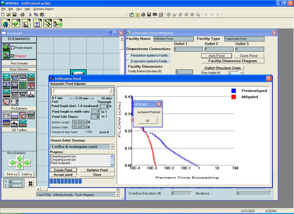
14 14
.")
15 The AutoPond partial infiltration results show a pond with a bottom length and width of feet. This produces a pond surface area of 0.54 acres; that is not much smaller than the full infiltration results (0.58 acres). If we look at the flow duration results in the Analysis window we see that the red Mitigated flow duration curve has much room for improvement to match (or get closer to) the blue Predeveloped flow duration curve at the bottom end of the curve. We can increase the bottom orifice diameter to increase the duration numbers of the lower end of the Mitigated flow duration curve. 15
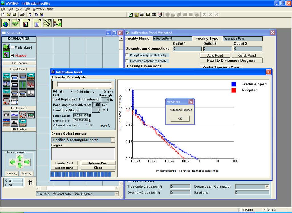
16 We increase the bottom orifice diameter from 1.2 inches to 2.0 inches to increase the lower discharge flows. We make the riser notch very small because if too much water goes through the notch then we increase the flows at the upper end of the flow duration curve and we don t have much extra room at the upper end for more flows. We click on Run Scenario to manually run the model. Then we can look at the flow duration results in the Analysis window. 16
17 We have improved the Mitigated flow duration curve with these changes to the outlet structure dimensions. We can now go back to AutoPond and use the Optimize feature to reduce the size of the infiltration pond. 17
18 When we use Optimize Pond to optimize a pond (any pond with or without infiltration) WWHM4 will take the existing pond facility dimensions and outlet structure data and use that information as its starting condition. We do not have to set the level of optimization (the slider at the top) because AutoPond will automatically use the highest level of optimization when we click on the Optimize Pond button. However, because our infiltration pond has vertical side walls we need to change the pond side slopes from the default value of 3 to the new value of 0. We click Optimize Pond and stand back and watch the action. 18
19 19
20 Using Optimize Pond and our initial bottom length and width of feet, we reduced these dimensions to feet. This corresponds to a surface area of acres. This is not a great improvement over our previous pond size, but every little bit helps. To summarize: 1. We initially size aside acres for the infiltration pond area. 2. We designed an infiltration pond with full (100%) infiltration. The pond surface area had to be expanded from acres to acres. 3. We sized the infiltration pond for partial infiltration using AutoPond s Create Pond feature. This action reduced the pond surface area from acres to acres. 4. We adjusted the infiltration pond riser orifice and notch dimensions and then used the Optimize Pond feature of AutoPond to make the pond smaller. This reduced the pond surface area from acres to acres. Partial infiltration makes the infiltration pond smaller, but the decrease in pond size is highly dependent on the relative amount of high and low infiltrating soils draining to the pond and the proportion of impervious to pervious area in the Mitigated development scenario. Partial infiltration works best in low infiltrating soils and relatively small amounts of impervious area. 20
21 SUMMARY: 1. Locate project site on map. 2. Input Predeveloped and Mitigated land use information for the project basin. Connect Predeveloped basin to POC 1. Manually Predeveloped scenario. 3. Add a pond to Mitigated scenario. Connect pond to POC Input initial pond dimensions, riser information, and infiltration data. 5. For full (100%) infiltration click on Size Infiltration Pond. 6. For partial (less than 100%) infiltration use AutoPond to size the infiltration pond. 7. First use the Create Pond option in AutoPond to generate pond dimensions and outlet configuration data. 8. Look at flow duration curves in Analysis window. 9. Adjust outlet configuration data if necessary and use Optimize Pond to further reduce pond size. 10. Look at Report project report results. 11. Finished. 21
Porous Pavement Flow Paths
 POROUS PAVEMENT MODELING Clear Creek Solutions, Inc., 2010 Porous pavement includes porous asphalt or concrete and grid/lattice systems (nonconcrete) and paving blocks. The use of any of these types of
LID PLANTER BOX MODELING
 LID PLANTER BOX MODELING Clear Creek Solutions, Inc., 2010 Low Impact Development (LID) planter boxes are small, urban stormwater mitigation facilities. They are rain gardens in a box. WWHM4 provides the
Bay Area Hydrology Model
 Bay Area Hydrology Model Doug Beyerlein, P.E. Joe Brascher Shanon White Clear Creek Solutions, Inc. www.clearcreeksolutions.com Bay Area Hydrology Model This introductory presentation was given at BAHM
Western Washington Hydrology Model Version 3.0. User Manual
 Western Washington Hydrology Model Version 3.0 User Manual August 2006 Western Washington Hydrology Model Version 3.0 User Manual Prepared by Clear Creek Solutions, Inc. August 2006 To download the Western
Western Washington Hydrology Model (WWHM) Software Introduction. Doug Beyerlein, P.E., P.H., D.WRE Clear Creek Solutions, Inc. Mill Creek, Washington
 Software Introduction. Doug Beyerlein, P.E., P.H., D.WRE Clear Creek Solutions, Inc. Mill Creek, Washington") Western Washington Hydrology Model (WWHM) Software Introduction Doug Beyerlein, P.E., P.H., D.WRE Clear Creek Solutions, Inc. Mill Creek, Washington Clear Creek Solutions Hydrology Expertise Clear Creek
Western Washington Hydrology Model (WWHM) Software Introduction Doug Beyerlein, P.E., P.H., D.WRE Clear Creek Solutions, Inc. Mill Creek, Washington Clear Creek Solutions Hydrology Expertise Clear Creek
Bay Area Hydrology Model. User Manual
 Bay Area Hydrology Model User Manual Prepared by Clear Creek Solutions, Inc. www.clearcreeksolutions.com Prepared for Alameda Countywide Clean Water Program San Mateo Countywide Water Pollution Prevention
Bay Area Hydrology Model User Manual
 Bay Area Hydrology Model 2013 User Manual Prepared by Clear Creek Solutions, Inc. www.clearcreeksolutions.com Prepared for Alameda Countywide Clean Water Program San Mateo Countywide Water Pollution Prevention
The Bay Area Hydrology Model A Tool for Analyzing Hydromodification Effects of Development Projects and Sizing Solutions
 The Bay Area Hydrology Model A Tool for Analyzing Hydromodification Effects of Development Projects and Sizing Solutions Jill Bicknell, P.E., EOA, Inc., Santa Clara Valley Urban Runoff Pollution Prevention
SECTION 4 SURFACE WATER MANAGEMENT DESIGN AND CONSTRUCTION REQUIREMENTS
 SECTION 4 SURFACE WATER MANAGEMENT DESIGN AND CONSTRUCTION REQUIREMENTS Page 4-1 INTRODUCTION 4-3 4-1.01 Applicability of VMCs 14.24, 14.25, 14.26 4-4 4-1.02 Minimum Requirements - Projects Below Threshold
San Diego Hydrology Model (SDHM 3.0) Reviewer Workshop. Doug Beyerlein, P.E., P.H., D.WRE Clear Creek Solutions, Inc. Mill Creek, Washington
 Reviewer Workshop. Doug Beyerlein, P.E., P.H., D.WRE Clear Creek Solutions, Inc. Mill Creek, Washington") San Diego Hydrology Model (SDHM 3.0) Reviewer Workshop Doug Beyerlein, P.E., P.H., D.WRE Clear Creek Solutions, Inc. Mill Creek, Washington Clear Creek Solutions Hydrology Expertise Clear Creek Solutions,
San Diego Hydrology Model (SDHM 3.0) Reviewer Workshop Doug Beyerlein, P.E., P.H., D.WRE Clear Creek Solutions, Inc. Mill Creek, Washington Clear Creek Solutions Hydrology Expertise Clear Creek Solutions,
Chapter 2 - Hydrologic Analysis
 Chapter - Hydrologic Analysis The broad definition of hydrology is the science which studies the source, properties, distribution, and laws of water as it moves through its closed cycle on the earth (the
City of Gig Harbor Stormwater Management and Site Development Manual
 City of Gig Harbor Stormwater Management and Site Development Manual Volume III Hydrologic Analysis and Flow Control BMPs Prepared by: Pierce County Surface Water Management Modified by: City of Gig Harbor
Sizing Calculations and Design Considerations for LID Treatment Measures
 SCVURPPP C.3 Workshop December 18, 2012 Sizing Calculations and Design Considerations for LID Treatment Measures Jill Bicknell, P.E., EOA, Inc. Santa Clara Valley Urban Runoff Pollution Prevention Program
INFLOW DESIGN FLOOD CONTROL SYSTEM PLAN PLANT GREENE COUNTY ASH POND ALABMA POWER COMPANY
 INFLOW DESIGN FLOOD CONTROL SYSTEM PLAN PLANT GREENE COUNTY ASH POND ALABMA POWER COMPANY Section 257.82 of EPA s regulations requires the owner or operator of an existing or new CCR surface impoundment
City of Tacoma Regional Stormwater Facility Plan: ATTACHMENT 1: FLETT CREEK WATERSHED
 City of Tacoma Regional Stormwater Facility Plan: ATTACHMENT 1: FLETT CREEK WATERSHED Aerial Photo of Flett Holding Ponds and Flett Wetlands Gravel Pit Stormwater Regional Facility and Outlet Structure
Hydrologic Study Report for Single Lot Detention Basin Analysis
 Hydrologic Study Report for Single Lot Detention Basin Analysis Prepared for: City of Vista, California August 18, 2006 Tory R. Walker, R.C.E. 45005 President W.O. 116-01 01/23/2007 Table of Contents Page
Chapter 3 Dispersion BMPs
 Chapter 3 Dispersion BMPs 3.1 BMP L611 Concentrated Flow Dispersion 3.1.1 Purpose and Definition Dispersion of concentrated flows from driveways or other pavement through a vegetated pervious area attenuates
Pennsylvania Stormwater Best Management Practices Manual. Chapter 3. Stormwater Management Principles and Recommended Control Guidelines
 Pennsylvania Stormwater Best Management Practices Manual Chapter 3 Stormwater Management Principles and Recommended Control Guidelines 363-0300-002 / December 30, 2006 Chapter 3 Stormwater Management Principles
INFLOW DESIGN FLOOD CONTROL SYSTEM PLAN PLANT BARRY ASH POND ALABAMA POWER COMPANY
 INFLOW DESIGN FLOOD CONTROL SYSTEM PLAN PLANT BARRY ASH POND ALABAMA POWER COMPANY Section 257.82 of EPA s regulations requires the owner or operator of an existing or new CCR surface impoundment or any
Continuous Simulation Modeling of Stormwater Ponds, Lakes, & Wetlands: A BUILT-IN APPLICATION OF PONDS 3.2
 Continuous Simulation Modeling of Stormwater Ponds, Lakes, & Wetlands: A BUILT-IN APPLICATION OF PONDS 3.2 PRESENTED AT THE SFWMD WORKSHOP PRE-DEVELOPMENT VERSUS POST DEVELOPMENT RUNOFF VOLUME ANALYSIS
Rainfall, runoff and sediment transport in the Napa River watershed: now and a possible future
 Rainfall, runoff and sediment transport in the Napa River watershed: now and a possible future Lester McKee San Francisco Estuary Institute 5/24/2017 1 The importance of the natural water cycle of infiltration
Background / Regulatory Requirements
 Chapter 2 Background / Regulatory Requirements This Chapter summarizes the impacts of development on stormwater quality and quantity and explains the postconstruction stormwater control requirements for
HYDROLOGIC CONSIDERATIONS. 22 nd Annual Nonpoint Source Pollution Conference Saratoga Springs, NY
 LOW IMPACT DEVELOPMENT HYDROLOGIC CONSIDERATIONS 22 nd Annual Nonpoint Source Pollution Conference Saratoga Springs, NY May 18, 2011 PRESENTATION AGENDA Introduction Definitions Discuss Impacts to Hydrologic
NEW CASTLE CONSERVATION DISTRICT. through. (Name of Municipality) PLAN REVIEW APPLICATION DRAINAGE, STORMWATER MANAGEMENT, EROSION & SEDIMENT CONTROL
 PLAN REVIEW APPLICATION DRAINAGE, STORMWATER MANAGEMENT, EROSION & SEDIMENT CONTROL") NEW CASTLE CONSERVATION DISTRICT through (Name of Municipality) PLAN REVIEW APPLICATION DRAINAGE, STORMWATER MANAGEMENT, EROSION & SEDIMENT CONTROL Office use only: Received by Municipality: Received by
NEW CASTLE CONSERVATION DISTRICT through (Name of Municipality) PLAN REVIEW APPLICATION DRAINAGE, STORMWATER MANAGEMENT, EROSION & SEDIMENT CONTROL Office use only: Received by Municipality: Received by
Hydrology Study. Ascension Heights Subdivision Ascension Drive at Bel Aire Road San Mateo, California (Unincorporated)
") Hydrology Study Ascension Heights Subdivision Ascension Drive at Bel Aire Road San Mateo, California (Unincorporated) Prepared for San Mateo Real Estate & Construction March 9, 21 Rev. 1 11-8-211 Rev.
Hydrology Study Ascension Heights Subdivision Ascension Drive at Bel Aire Road San Mateo, California (Unincorporated) Prepared for San Mateo Real Estate & Construction March 9, 21 Rev. 1 11-8-211 Rev.
Project Name: Add a unique name that appropriately identifies the submission
 PTAPP Online Municipal Tracking Tool Instructions Project Name: Add a unique name that appropriately identifies the submission Municipal Project: Check this box if the project is part of municipal efforts
Pre-Treatment Bioretention Cells Bioswales IOWA STORMWATER MANAGEMENT MANUAL DECEMBER 16, 2015
 Pre-Treatment Bioretention Cells Bioswales IOWA STORMWATER MANAGEMENT MANUAL DECEMBER 16, 2015 Urban Runoff Background How we got here What Problem?? Provenance of the Problem Unified Sizing Criteria What
EXAMPLE Stormwater Management Plans w/ CSS BMP Sizing Calculator (v2.1)
") 525 Golden Gate Avenue, 11th Floor San Francisco, CA 94102 EXAMPLE Stormwater Management Plans w/ CSS BMP Sizing Calculator (v2.1) The following example Stormwater Management Plans (SMPs) are provided
525 Golden Gate Avenue, 11th Floor San Francisco, CA 94102 EXAMPLE Stormwater Management Plans w/ CSS BMP Sizing Calculator (v2.1) The following example Stormwater Management Plans (SMPs) are provided
Hydrologic Impacts of Exceeding Zoning Ordinances. on Impervious Lot Coverage: TR-55 modeling of three. Zoning Districts in Shippensburg Borough
 Hydrologic Impacts of Exceeding Zoning Ordinances on Impervious Lot Coverage: TR-55 modeling of three Zoning Districts in Shippensburg Borough Practical Exam-Revisions Kristina Everetts November 19, 2013
Preliminary Drainage Analysis
 Preliminary Drainage Analysis Tanimura and Antle Employee Housing Town of Spreckels County of Monterey, California LIB150205 May 29, 2015 Prepared For: Tanimura and Antle Produce Prepared By: 9699 Blue
Water Balance Methodology
 Water Balance Methodology Integrating the Site with the Watershed and the Stream March 2012 An initiative under the umbrella of the Water Sustainability Action Plan for British Columbia Water Balance Methodology
A Case for the Design and Modeling of BMP Infiltration and LID Techniques. By: Bob Murdock
 A Case for the Design and Modeling of BMP Infiltration and LID Techniques 2009 IAFSM Annual Conference 2009 IAFSM Annual Conference By: Bob Murdock Presentation Outline 1. Runoff Reduction (RR) and Low
City of Redwood City Stormwater Pollution Prevention Program. Drainage Guidelines for Residential Development
 City of Redwood City Stormwater Pollution Prevention Program Drainage Guidelines for Residential Development General Requirements A. Plot & Finished Grading Plan must be submitted with Building Permit
4.8. Subsurface Infiltration
 4.8. Subsurface Infiltration Subsurface infiltration systems are designed to provide temporary below grade storage infiltration of stormwater as it infiltrates into the ground. Dry wells, infiltration
SUBSURFACE INFILTRATION SYSTEM DESCRIPTION. Alternative Names: Sump, Drywell, Infiltration Trench, Infiltration Galleries, Leach Fields
 4.1-d SUBSURFACE INFILTRATION SYSTEM Alternative Names: Sump, Drywell, Infiltration Trench, Infiltration Galleries, Leach Fields BMP DESIGN APPROACH Pollutant Source Control Hydrologic Source Control Stormwater
APPENDIX IV. APPROVED METHODS FOR QUANTIFYING HYDROLOGIC CONDITIONS OF CONCERN (NORTH ORANGE COUNTY)
") APPENDIX IV. APPROVED METHODS FOR QUANTIFYING HYDROLOGIC CONDITIONS OF CONCERN (NORTH ORANGE COUNTY) Hydromodification design criteria for the North Orange County permit area are based on the 2- yr, 24-hr
APPENDIX IV. APPROVED METHODS FOR QUANTIFYING HYDROLOGIC CONDITIONS OF CONCERN (NORTH ORANGE COUNTY) Hydromodification design criteria for the North Orange County permit area are based on the 2- yr, 24-hr
A HYDROLOGY MODEL FOR MIMICKING PRE AND POST DEVELOPMENT RUNOFF VOLUMES
 A HYDROLOGY MODEL FOR MIMICKING PRE AND POST DEVELOPMENT RUNOFF VOLUMES Mr. Randel Lemoine AUTHOR: Fort Benning, DPW Engineering Division, Meloy Dr. Bldg 6, RM 320-T, Fort Benning, Georgia, 315. REFERENCE:
BMP #: Infiltration Basin
 Structural BMP Criteria BMP #: Infiltration Basin An Infiltration Basin is a shallow impoundment that stores and infiltrates runoff over a level, subtle, uncompacted, (preferably undisturbed area) with
INFLOW DESIGN FLOOD CONTROL SYSTEM PLAN 40 C.F.R. PART PLANT YATES ASH POND 3 (AP-3) GEORGIA POWER COMPANY
 GEORGIA POWER COMPANY") INFLOW DESIGN FLOOD CONTROL SYSTEM PLAN 40 C.F.R. PART 257.82 PLANT YATES ASH POND 3 (AP-3) GEORGIA POWER COMPANY EPA s Disposal of Coal Combustion Residuals from Electric Utilities Final Rule (40 C.F.R.
INFLOW DESIGN FLOOD CONTROL SYSTEM PLAN 40 C.F.R. PART 257.82 PLANT YATES ASH POND 3 (AP-3) GEORGIA POWER COMPANY EPA s Disposal of Coal Combustion Residuals from Electric Utilities Final Rule (40 C.F.R.
EFFECT OF UPSTREAM DEVELOPMENT ON THE CLEAR CREEK AREA
 EFFECT OF UPSTREAM DEVELOPMENT ON THE CLEAR CREEK AREA Technical Memorandum Farming in the Floodplain Project Prepared for May 2017 PCC Farmland Trust Photo credit: Google Earth TABLE OF CONTENTS Page
Grass Channel STORMWATER MANAGEMENT SUITABILITY KEY CONSIDERATIONS
 4.0 Structural Stormwater Control Description: Vegetated open channels designed to filter stormwater runoff and meet velocity targets for the water quality design storm and the Streambank Protection storm
4.8. Subsurface Infiltration
 4.8. Subsurface Infiltration Subsurface infiltration systems are designed to provide temporary below grade storage infiltration of storm water as it infiltrates into the ground. Dry wells, infiltration
Appendix G: Hydrology-Related Reports
 Appendix G: Hydrology-Related Reports (Hydraulic Summary of the Proposed Hawk Street Bridge, Bay Area Hydrology Model Project Report, Preliminary Stormwater Treatment Plan and Details, Evaluation of Potential
LID & Detention Pond Sizing Tool to Address Hydromodification and Water Quality in Clackamas County
 LID & Detention Pond Sizing Tool to Address Hydromodification and Water Quality in Clackamas County Leah Johanson, Water Environment Services February 12 th, 2015 Agenda» WES History/Stormwater Standards»
SITE DESIGN ENGINEERING, LLC. 11 Cushman Street, Middleboro, MA P: F:
 INTRODUCTION This drainage report was prepared for the proposed site re-development at in Burlington, Massachusetts. The project site is approximately 1.05± acres consisting of approximately 70% impervious
Analysis of Runoff Reduction and Hydrologic Cycle Utilizing LID Concepts
 Maine Stormwater Conference (Portland, ME, 2015) Analysis of Runoff Reduction and Hydrologic Cycle Utilizing LID Concepts Park Jongpyo, Lee Kyoungdo: HECOREA. INC Shin Hyunsuk: Busan National University
INSTRUCTIONS TO FILL OUT WASTEWATER DISCHARGE PERMIT APPLICATION BASELINE MONITORING REPORT
 INSTRUCTIONS TO FILL OUT WASTEWATER DISCHARGE PERMIT APPLICATION BASELINE MONITORING REPORT All questions must be answered. DO NOT LEAVE BLANKS. If a question is not applicable, indicate so on the form.
Stormwater Volume and Treatment Methods Simplifying the Numbers. IAFSM March 10, Presented by: Tom Powers P.E., CFM, LEED AP, CPESC
 Stormwater Volume and Treatment Methods Simplifying the Numbers IAFSM March 10, 2011 Presented by: Tom Powers P.E., CFM, LEED AP, CPESC Introduction GOALS: Improve understanding of Rate and Volume (Quantity)
Module 10b: Gutter and Inlet Designs and Multiple Design Objectives
 Module 10b: Gutter and Inlet Designs and Multiple Design Objectives Bob Pitt University of Alabama and Shirley Clark Penn State Harrisburg Evening traffic plows through high water at the intersection of
Catch Basin Inserts: Method to Determine CB Inserts Act as Full Capture Devices
 WATERSHED PROTECTION DIVISION DEPARTMENT OF PUBLIC WORKS BUREAU OF SANITATION CITY OF LOS ANGELES Catch Basin Inserts: Method to Determine CB Inserts Act as Full Capture Devices Catch Basin Inserts: Method
c h a p t e r 4 d e s i g n e x a m p l e s f o r s a n m a t e o c o u n t y A typical residential street intersection
 LOW-DENSITY RESIDENTIAL STREETS: Stormwater Curb Extensions A typical residential street intersection This residential street example illustrates how stormwater curb extensions can be easily retrofitted
the 2001 season. Allison brought high winds and street flooding to Houston, after
 Module 10b: Gutter and Inlet Designs and Multiple Design Objectives Bob Pitt University of Alabama and Shirley Clark Penn State Harrisburg Evening traffic plows through high water at the intersection of
WHATCOM COUNTY STANDARD FARM CONSERVATION PLAN PLANNING WORKBOOK: Checklist and Action Plan
 WHATCOM COUNTY STANDARD FARM CONSERVATION PLAN PLANNING WORKBOOK: Checklist and Action Plan For use with the publication: Tips on Land and Water Management For: Land Owner Address Date Introduction Conservation
The SuDS Manual Frequently asked questions
 The SuDS Manual Frequently asked questions 1. Is source control still a requirement of the new SuDS Manual? Yes. Source control components are fundamental elements of a SuDS scheme. The benefits of source
Determination of Design Infiltration Rates for the Sizing of Infiltration based Green Infrastructure Facilities
 Determination of Design Infiltration Rates for the Sizing of Infiltration based Green Infrastructure Facilities 1 Introduction This document, developed by the San Francisco Public Utilities Commission
Construction Inspection Checklists
 III. Construction Inspection Checklists 33 Bioretention - Construction Inspection Checklist Project: Location: Site Status: Date: Time: Inspector: Construction Sequence Satisfactory / Unsatisfactory Comments
Runoff Volume: The Importance of Land Cover
 Runoff Volume: The Importance of Land Cover Grade Level: 9-12 Time: 1-2 class periods Learning Objectives: - Quantify the volume of water that runs off different land uses in a watershed. - Analyze the
INFLOW DESIGN FLOOD CONTROL SYSTEM PLAN 40 C.F.R. PART PLANT YATES ASH POND B (AP-B ) GEORGIA POWER COMPANY
 GEORGIA POWER COMPANY") INFLOW DESIGN FLOOD CONTROL SYSTEM PLAN 40 C.F.R. PART 257.82 PLANT YATES ASH POND B (AP-B ) GEORGIA POWER COMPANY EPA s Disposal of Coal Combustion Residuals from Electric Utilities Final Rule (40 C.F.R.
INFLOW DESIGN FLOOD CONTROL SYSTEM PLAN 40 C.F.R. PART 257.82 PLANT YATES ASH POND B (AP-B ) GEORGIA POWER COMPANY EPA s Disposal of Coal Combustion Residuals from Electric Utilities Final Rule (40 C.F.R.
6.0 Runoff. 6.1 Introduction. 6.2 Flood Control Design Runoff
 October 2003, Revised February 2005 Chapter 6.0, Runoff Page 1 6.1 Introduction 6.0 Runoff The timing, peak rates of discharge, and volume of stormwater runoff are the primary considerations in the design
Treatment Volume: Curve Numbers. Composite CN or Not? Treatment Volume: Curve Numbers. Treatment Volume: Calculation. Treatment Volume: Calculation
 Stormwater Engineering Bioretention Design Bill Hunt, PE, Ph.D. Extension Specialist & Assistant Professor NCSU-BAE www.bae.ncsu.edu/stormwater Bioretention Design Six Step Process 1 Determine Volume to
TECHNICAL GUIDANCE DOCUMENT APPENDICES
 XIV.4. Harvest and Use BMP Fact Sheets (HU) HU-1: Above-Ground Cisterns Cisterns are large rain barrels. While rain barrels are less than 100 gallons, cisterns range from 100 to more than 10,000 gallons
Sizing Criteria Worksheets and Examples
 Appendix B Sizing Criteria Worksheets and Examples This Appendix provides sizing criteria worksheets and examples to illustrate the correct procedures for determining the water quality design flow and
Infiltration Guidelines
 Appendix E Infiltration Guidelines As a stormwater management method, infiltration means retaining or detaining water within soils to reduce runoff. Infiltration can be a cost-effective method to manage
COON CREEK WATERSHED DISTRICT PERMIT REVIEW. Spring Lake Park Schools Westwood Middle School st Avenue NE, Spring Lake Park, MN 55432
 PAN 16-112, Westwood Middle School, Page 1 of 6 COON CREEK WATERSHED DISTRICT PERMIT REVIEW MEETING DATE: August 22, 2016 AGENDA NUMBER: 10 FILE NUMBER: 16-112 ITEM: Westwood Middle School RECOMMENDATION:
HYDROLOGIC-HYDRAULIC STUDY ISABELLA OCEAN RESIDENCES ISLA VERDE, CAROLINA, PR
 HYDROLOGIC-HYDRAULIC STUDY ISABELLA OCEAN RESIDENCES ISLA VERDE, CAROLINA, PR 1 INTRODUCTION 1.1 Project Description and Location Isabella Ocean Residences is a residential development to be constructed
7/16/2012. Post Construction Best Management Practices (PCBMPs) Article VIII: Post Construction Best Management Practices
 Article VIII: Post Construction Best Management Practices") Post Construction Best Management Practices (PCBMPs) Article VIII: Post Construction Best Management Practices Presented by Jennifer Boyer DuPage County DEC Includes BMPs intended to provide volume control
Post Construction Best Management Practices (PCBMPs) Article VIII: Post Construction Best Management Practices Presented by Jennifer Boyer DuPage County DEC Includes BMPs intended to provide volume control
N.J.A.C. 7:8 Stormwater Management Rules - Design and Performance Standards. Nonstructural Strategies Assist with Strategy #2; See Page 3
 9.3 DRY WELLS Dry wells are subsurface stormwater facilities that are used to collect and temporarily store runoff from clean rooftops; runoff is discharged through infiltration into the subsoil. Dry wells
CHAPTER 3 STORMWATER HYDROLOGY. Table of Contents SECTION 3.1 METHODS FOR ESTIMATING STORMWATER RUNOFF
 CHAPTER 3 STORMWATER HYDROLOGY Table of Contents SECTION 3.1 METHODS FOR ESTIMATING STORMWATER RUNOFF 3.1.1 Introduction to Hydrologic Methods...3.1-1 3.1.2 Symbols and Definitions...3.1-3 3.1.3 Rainfall
Activity Calculating Property Drainage
 Page 1 of 5 Activity 2.3.11 Calculating Property Drainage Introduction When a property is developed, it is important to understand that changes to watershed characteristics (i.e., land use, slope, soil
To The Applicant For A Small Wastewater System Permit Sheridan County, Wyoming
 To The Applicant For A Small Wastewater System Permit Sheridan County, Wyoming PRIOR TO SUBMITTING APPLICATION 1) Ground water test pit This pit is required to be inspected by a representative of Sheridan
Hydrology 101. Impacts of the Urban Environment. Nokomis Knolls Pond Summer June 2008
 Hydrology 101 Nokomis Knolls Pond Summer 2002 Impacts of the Urban Environment Hydrologic Cycle; What is it? Geography, Topography, Geology, Land Cover and Climate determine the Amount and Behavior of
IV. ENVIRONMENTAL IMPACT ANALYSIS G. HYDROLOGY/WATER QUALITY
 IV. ENVIRONMENTAL IMPACT ANALYSIS G. HYDROLOGY/WATER QUALITY ENVIRONMENTAL SETTING The project site is located in the Wilshire community of the City of Los Angeles and is bound by S. Wetherly Drive to
Summary of Detention Pond Calculation Canyon Estates American Canyon, California
 July 15, 2015 Bellecci & Associates, Inc Summary of Detention Pond Calculation Canyon Estates American Canyon, California 1. Methodology: Method: Unit Hydrograph Software: Bentley Pond Pack Version 8i
New Castle County, DE. Floodplain Regulations
 New Castle County, DE Floodplain Regulations John J. Gysling, PE CFM Department of Land Use New Castle County, DE February 26, 2009 Today s Presentation Floodplain Protection and Uses Terms and Definitions
Permeable Pavement for Stormwater Management Porous Pavement
 Permeable Pavement for Stormwater Management Porous Pavement Advanced Permeable Pavement for Stormwater Management Water Quality Design Using WinSLAMM Presented by John Voorhees Water Resources Engineer
Constructed Wetland Pond T-8
 Constructed Wetland Pond T-8 Description A constructed wetlands pond is a shallow retention pond designed to permit the growth of wetland plants such as rushes, willows, and cattails. Constructed wetlands
Municipal Stormwater Ordinances Summary Table
 APPENDIX F Municipal Ordinances Summary Table Municipality Abington Bryn Athyn Borough Hatboro Borough Ordinance, SALDO Runoff equals pre post Erosion Sediment Control Water Quality Requirements Any which
BMP 6.4.4: Infiltration Trench
 BMP 6.4.4: Infiltration Trench An Infiltration Trench is a leaky pipe in a stone filled trench with a level bottom. An Infiltration Trench may be used as part of a larger storm sewer system, such as a
E. STORMWATER MANAGEMENT
 E. STORMWATER MANAGEMENT 1. Existing Conditions The Project Site is located within the Lower Hudson Watershed. According to the New York State Department of Environmental Conservation (NYSDEC), Lower Hudson
FocalPoint as an Acceptable Alternative Biofiltration Practice
 FocalPoint as an Acceptable Alternative Biofiltration Practice In the last few years, most California cities have begun regulating the permanent stormwater BMPs that are required to be implemented with
Decatur, Georgia Stormwater Management Policy Guidelines. DRAFT November 5, 2014
 Decatur, Georgia Stormwater Management Policy Guidelines Stormwater Management Policy Guidelines Decatur, Georgia STORMWATER MANAGEMENT POLICY GUIDELINES 1.0 Introduction... 3 2.0 Determining Predevelopment
Chatham Park Stormwater Manual
 Chatham Park Stormwater Manual Table of Contents A. Introduction... 2 B. Calculation Methods... 2 C. BMP Design Standards... 3 D. Compliance Points... 3 E. Critical Environmental Resources... 3 F. Submittal
Considerations In Estimating Tailwater Elevations
 Considerations In Estimating Tailwater Elevations by Alphonse (Al) J. Stewart, P.E., President www.suncam.com Page 1 of 39 ************************************************************************ This
WATERSHED AUDITS Auditing Stormwater Best Management Practices (BMPs) This Presentation Posted At ceds.org/audit
 This Presentation Posted At ceds.org/audit") WATERSHED AUDITS Auditing Stormwater Best Management Practices (BMPs) This Presentation Posted At ceds.org/audit 1 No Need To Take Notes Download these publication at: ceds.org/audit Why You Are Critical
WATERSHED AUDITS Auditing Stormwater Best Management Practices (BMPs) This Presentation Posted At ceds.org/audit 1 No Need To Take Notes Download these publication at: ceds.org/audit Why You Are Critical
Constructed Wetland Channel T-9
 Description A constructed wetland channel is a conveyance BMP that is built, in part, to enhance stormwater quality. Constructed wetland channels use dense vegetation to slow down runoff and allow time
Urban Water Security Research Alliance
 Urban Water Security Research Alliance Can Stormwater Harvesting Restore Pre-Development Flows in urban catchments in South East Queensland? Stephanie Ashbolt Stormwater Harvesting and Ecohydrology Science
STORMWATER RUNOFF AND WATER QUALITY IMPACT REVIEW
 SUBCHAPTER 8 STORMWATER RUNOFF AND WATER QUALITY IMPACT REVIEW 7:45-8.1 Purpose and scope of review Except for those projects expressly exempted by this chapter or waived by the Commission, the Commission
Pennsylvania Stormwater Best Management Practices Manual. Section 3 Stormwater Management Principles, Goals, and a Management Model
 Pennsylvania Stormwater Best Management Practices Manual DRAFT - JANUARY 2005 Section 3 Stormwater Management Principles, Goals, and a Management Model This page intentionally left blank. Section 3 Stormwater
Software Applications for Runoff Hydrological Assessment
 Bulletin UASVM Horticulture, 67(2)/2010 Print ISSN 1843-5254; Electronic ISSN 1843-5394 Software Applications for Runoff Hydrological Assessment Severin CAZANESCU 1), Sorin CIMPEANU 1), Oana GUI 2), Dana
Stormwater Management Criteria
 FOR OFFICE USE ONLY Stormwater Management Criteria Form #PWU005 (rev. 11/16) Approving Agency Performance Standards Applicability for Control of Stormwater Pollution Applicability for Control of Peak Runoff
National Stormwater Calculator User s Guide
 United States Environmental Protection Agency EPA/600/R-13/085 July 2013 www.epa.gov/nrmrl/wswrd/wq/models/swc/ National Stormwater Calculator User s Guide Traditional Infrastructure Green Infrastructure
Lyon Creek Cedar Way Stormwater Detention Dam Operation and Maintenance Manual
 Lyon Creek Cedar Way Stormwater Detention Dam Operation and Maintenance Manual Prepared by: Mike Shaw Stormwater Program Manager City of Mountlake Terrace January 2010 Section I General Information This
Orange County Fertilizer Application Education Course for Citizens
 Orange County Fertilizer Application Education Course for Citizens Thanks for taking the time to learn how to keep Central Florida beautiful while protecting our water quality! Why is Orange County Requiring
Hydrology is the study of the movement
 G3691-2 The Wisconsin Storm Water M A N U A L Numerous methods are used to predict runoff peaks and volumes and routing flows (See for example Pitt, 1989; USDA- SCS, 1986; Walker, 1990). Two commonly used
Implementing Stormwater Management through Split-Flow Drainage Design
 Implementing Stormwater Management through Split-Flow Drainage Design Stuart Patton Echols PhD, ASLA, RLA Assistant Professor - Department of Landscape Architecture 210 Engineering Unit D Center for Watershed
Sunset Circle Vegetated Swale and Infiltration Basin System Monitoring Report: Rainy Seasons and
 Sunset Circle Vegetated Swale and Infiltration asin System Monitoring Report: Rainy Seasons 2012-13 and 2013-14 bstract Site Summary Project Features Sunset Circle Vegetated swales and infiltration basins
Bioreactor Landfill Design
 Bioreactor Landfill Design Timothy Townsend, PhD, PE Department of Environmental Engineering Sciences University of Florida ttown@ufl.edu Bioreactor Landfill Design Modern landfill design entails many
PART 3 - STANDARDS FOR SEWERAGE FACILITIES DESIGN OF STORM SEWERS
 PART 3 - STANDARDS FOR SEWERAGE FACILITIES 3.3 - DESIGN OF STORM SEWERS 3.301 Design of Storm Sewers A. General Information B. Investigations and Surveys C. Special Projects 3.302 Design Criteria for Storm
Applicant s Handbook, Volume II (including Appendices A through F`) is Incorporated by Reference in Rule , F.A.C.
 is Incorporated by Reference in Rule , F.A.C.") REFERENCES AND DESIGN AIDS FOR THE ENVIRONMENTAL RESOURCE PERMIT APPLICANT S HANDBOOK VOLUME II FOR USE WITHIN THE GEOGRAPHIC LIMITS OF THE NORTHWEST FLORIDA WATER MANAGEMENT DISTRICT Applicant s Handbook,
REFERENCES AND DESIGN AIDS FOR THE ENVIRONMENTAL RESOURCE PERMIT APPLICANT S HANDBOOK VOLUME II FOR USE WITHIN THE GEOGRAPHIC LIMITS OF THE NORTHWEST FLORIDA WATER MANAGEMENT DISTRICT Applicant s Handbook,
Chapter 5 Hydraulic Structures
 Chapter 5 Hydraulic Structures 5.1 Flow Splitter Designs 5.1.1 General Design Criteria A flow splitter must be designed to deliver the WQ design flow rate specified in this volume to the WQ treatment facility.