An Introduction to Turbine Inlet Cooling A Perspective on the U.S. Electric Power Industry... 6
|
|
|
- Griselda Reed
- 6 years ago
- Views:
Transcription
.")
1 An Introduction to Turbine Inlet Cooling A Perspective on the U.S. Electric Power Industry Evaporative Cooling Technologies for Turbine Inlet Cooling Chiller Technologies for Turbine Inlet Cooling Thermal Energy Storage Technologies for Turbine Inlet Cooling Hybrid Systems & LNG for Turbine Inlet Cooling (TIC) Turbine Inlet Cooling (TIC) Installation Success Stories Turbine Inlet Buyers Guide
2


3 Boost Turbine Output with Inlet-Air Chilling Meet growing power demand by optimizing power output with YORK chillers Don t add generators, boost output! Instead of adding gas-turbine generators to meet electricity demand which is forecast to jump 43% by 2020 you can enhance the output of existing generators with mechanical chillers from YORK. Based on proven water-chiller and heat exchanger technology, mechanical chillers provide the cooling capacity, dependability, and constant conditions for optimum output from the gas turbine. And thanks to relatively constant conditions provided by mechanical cooling, turbine life and maintainability may be significantly improved, too. Optimize with the best chiller option: YORK When you re selecting a liquid chiller for a turbine inlet-air-chilling (TIAC) system, consider YORK: the industrial cooling experts. YORK chillers and compressors are used in some of the most demanding, 24/7 petrochemical and gas-compression applications on Earth. That same industrial-grade dependability is built into the YORK chillers that serve as the heart of TIAC systems. Get the experience and options to optimize your installation. Call Bill McAuliffe at
4 COOL YOUR JETS Appeared in December 2003 Energy-Tech Magazine An Introduction to Turbine Inlet Cooling Dharam V. Punwani What is TIC? TIC is cooling of the air before it enters the compressor that supplies highpressure air to the combustion chamber from which hot air at high pressure enters the combustion turbine. TIC is also called by many other names, including combustion turbine inlet air cooling (CTIAC), turbine inlet air cooling (TIAC), combustion turbine air cooling (CTAC), and gas turbine inlet air cooling (GTIAC). Why Cool Turbine Inlet Air? The primary reason TIC is used is to enhance the power output of combustion turbines (CTs) when ambient air temperature is above 59 F. The rated capacities of all CTs are based on the standard ambient conditions of 59 F, 14.7 psia at sea level selected by the International Standards Organization (ISO). One of the common and unattractive characteristics of all CTs is that their power output decreases as the inlet air temperature increases as shown in Figure 1. It shows the effects of inlet air temperature on power output for two types of CTs: Aeroderivative and Industrial/Frame. The data in Figure 1 are typical for the two turbine types for discussion purposes. The actual characteristics of each CT could be different and depend on its actual design. The data in Figure 1 shows that for a typical aeroderivative CT, as inlet air temperature increases from 59 F to 100 F on a hot summer day (in Las Vegas, for example), its power output decreases to about 73 percent of its rated capacity. This could lead to power producers losing opportunity to sell more power just when the increase in ambient temperature increases power demand for operating air conditioners. By cooling the inlet air from 100 F to 59 F, we could prevent the loss of 27 percent of the rated generation capacity. In fact, if we cool the inlet air to about 42 F, we could enhance the power generation capacity of the CT to 110 percent of the rated capacity. Therefore, if we cool the inlet air from 100 F to 42 F, we could increase power output of an aeroderivative CT from 73 percent to 110 percent of the rated capacity or boost the output capacity by about 50 percent of the capacity at 100 F. The primary reason many power plants using CT cool the inlet air is to prevent loss of power output or even increase power output above the rated capacity when the ambient temperature is above 59 F. What are the Benefits of TIC? The primary benefit of TIC is that it allows the plant owners to prevent loss of CT output, compared to the rated capacity, when ambient temperature rises above 59 F or the plant is located in a warm/hot climate region. As discussed in the earlier section, TIC can even allow plant owners to increase the CT output above the rated capacity by cooling the inlet air to below 59 F. The secondary benefit of TIC is that it also prevents decrease in fuel efficiency of the CT due to increase in ambient temperature above 59 F. Figure 2 shows the effect of inlet air temperature on heat rate (fuel require per unit of electric energy) for the two types of CTs discussed in the earlier section. It shows that for an aeroderivative, CT increase in inlet air temperature from 59 F to 100 F increases heat rate (and thus, decreases fuel efficiency) by 4 percent (from 100 percent at 59 F to 104 percent at 100 F) and that cooling the inlet air from 59 F to 42 F reduces the heat rate (increases fuel efficiency) by about 2 percent (from 100 percent to about 98 percent). The other benefits of TIC include increased steam production in cogeneration Power Output, % of Rated Capacity Industrial Aeroderivative Heat Rate, % of Design Heat Rate 100 Industrial Aeroderivative Inlet Air Temperature, F Figure 1: Effect of Inlet Air Temperature on Combustion Turbine Power Output Inlet Air Temperature, F Figure 2: Effect of Ambient Temperature on Combustion Turbine Heat Rate 4
5 COOL YOUR JETS Appeared in December 2003 Energy-Tech Magazine plants, and increased power output of steam turbines in combined cycle systems. In summary, there are many benefits of TIC when the ambient temperature is above 59 F: Increased output of CT Reduced capital cost for the enhanced power capacity Increased fuel efficiency Increased steam production in cogeneration plants Increased power output of steam turbine in combined cycle plants How Does TIC Help Increase CT Output? Power output of a CT is directly proportional to and limited by the mass flow rate of compressed air available to it from the air compressor that provides highpressure air to the combustion chamber of the CT system. An air compressor has a fixed capacity for handling a volumetric flow rate of air. Even though the volumetric capacity of a compressor is fixed, the mass flow rate of air it delivers to the CT changes with changes in ambient air temperature. This mass flow rate of air decreases with increase in ambient temperature because the air density decreases when air temperature increases. Therefore, the power output of a combustion turbine decreases below its rated capacity at the ISO conditions (59 F, 14.7 psia at sea level) with increases in ambient temperature above 59 F. TIC allows increase in air density by lowering the temperature and thus, helps increase mass flow rate of air to the CT and results in increased output of the CT. Special Application Technologies i.e., re-vaporization of liquefied natural gas (LNG) Hybrid Systems: a mix of mechanical and absorption chillers All technologies listed above have advantages and disadvantages. Many published articles are available on these technologies. A number of these publications are listed in the Library section of the Turbine Inlet Cooling Association website ( What are the Economics of TIC? Even though it is difficult to generalize the overall economics of TIC because they depend on many factors, it generally requires less investment ($/kw) than installing additional uncooled CT to achieve similar increase in plant capacity. It is not unusual for TIC to increase CT output capacity at less than half the capital cost of installing an additional uncooled CT. The various factors that affect the overall economics of TIC include the following: Cooling Technology Weather data for the geographic location of the CT plant CT plant capacity and operational mode (Peaking, Cogeneration, or Combined Cycle) Market value of electric energy and power demand profile Price of fuel (Natural gas or fuel oil) Market value of cogenerated steam and steam demand profile Cost of capital Who is using TIC? Many CT plants across the U.S. and around the world are using various TIC technologies that improve their performance and economics. A database of some of these installations is available in the Experience Database section of the Turbine Inlet Cooling Association website. What are the Plans for this Column? This column will cover the following sequence of TIC topics in the subsequent issues of the Energy-Tech: Evaporative cooling technologies: wetted media, fogging, and overspraying/wet compression Refrigeration/Chiller technologies: mechanical and absorption Thermal energy storage technologies: ice, chilled water, and stratified fluid Special application technologies and hybrid systems Performance test protocol Commissioning, Maintenance & Operation What is the Mission of TICA? The mission of the Turbine Inlet Cooling Association (TICA), a not-forprofit organization, is to promote the development and exchange of knowledge related to TIC and to become the premier one-stop source of information on TIC. For more information about TICA, visit its website at What are the Available Technology Options for TIC? Many technologies are commercially available for TIC. These technologies can be divided into the following major categories/groups: Evaporative: wetted media, fogging, and wet compression/ overspray Refrigeration: mechanical and absorption chillers without or with thermal energy storage (TES) Dharam V. Punwani is president of Avalon Consulting, Inc. located in the Chicagoland area (Naperville), and has over 36 years of experience in energy technologies. Avalon provides technical and economic analyses related to TIC and cogeneration systems. He was chairman of TICA in 2002 and now serves as its Executive Director. 5

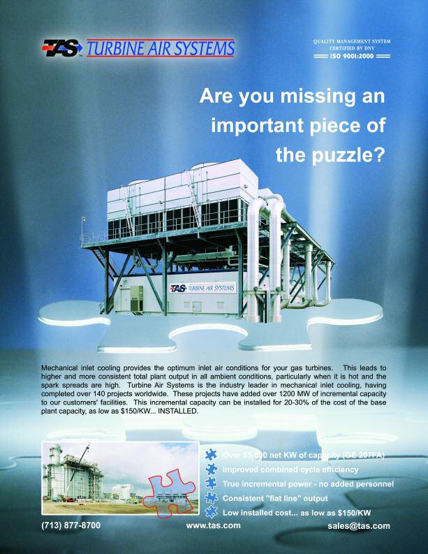
6 A Perspective on the U.S. Electric Power Industry PROBLEMS, SOLUTIONS & NEEDS By Craig M. Hurlbert Greater summer power demand and more advanced gas turbines lead to an increased need for turbine inlet chilling. Photo courtesy of TAS, Ltd. We all know that the U.S. electric power industry is one of the best in the world. However, it s far from perfect in that there are several structural problems which must be addressed and fixed as soon as possible. From the perspective of the electric power consumers and the environment, I believe the U.S. power industry problems include the following: Increasing grid instability High electricity cost during peak periods High environmental emissions during hot weather The lack of grid reliability generally occurs during hot weather when we need electric power the most. Some of the reliability problems stem from the aging grid infrastructure and some from the lack of sufficient supply to meet demand from the grid-connected loads. As we all know, the electric energy and demand charges are high during peak periods. Sometimes these charges are as much as five times as those during off-peak periods, and it is not because the power producers are gouging the consumers. The on-peak prices are influenced by two major factors: demand and supply, and the types of power plants brought on stream to meet peak loads. Many of these peaking plants have low energy efficiencies that increase the cost of producing electric power. In addition, when the weather becomes hot, the energy efficiency decreases and the cost of producing electric power increases for all power plants that use combustion turbines. Environmental emissions increase during hot weather for two reasons: decreased energy efficiency of all combustion turbines, and startup of older, dirtier, and inefficient peaking plants. Operating these power plants at low efficiencies not only increases environmental emissions, they also consume more fuel (natural gas, fuel oil, or diesel) per unit of electric energy produced. Over the last 20 years, most of the new power plants brought on stream in the U.S. use natural gas (Figure 1), and electric generation represents the highest demand sector for growth for natural gas (Figure 2). Natural gas demand for power 6
7 Oil Gas Year Source: National Petroleum Council, Sept. '03 Billion Kilowatt Hours New Electric Demand: Most New Generation Capacity Utilizes Natural Gas (Primarily for Environmental Reason) New Electric Demand: Electric Generation Represents the Highest Sector Demand Growth for Natural Gas History Projections Industrial Electric Generators Residential Commercial 2 CNG vehicles Source: Energy Information Administration, Annual Energy Outlook 2003 Figure 1 Figure 2 generation increases during summer (Figure 3). We all have seen the prices of natural gas peak much higher than ever before, while the average price of natural gas also seems to settle at a higher level than before (Figure 4). U.S. production of natural gas is not sufficient to meet demand; we now must import LNG to supplement it. Whether the combustion turbines use natural gas or oil, it is imperative that we not continue to operate our power systems at low efficiencies, particularly when much of the fuel source originates in an unstable and hostile region of the world. Solutions We need a multi-faceted approach for solving the problems within the power industry. This approach should include the following components: Modernizing grid infrastructure Demand side management Distributed generation Power augmentation We cannot afford to continue with the antiquated grid infrastructure - it must be modernized. Without it, all other approaches for improving grid reliability will never be adequate. Modernizing grid infrastructure is going to require a hefty budget from industry and government. It is not a nearterm solution; it will require significant time. Nonetheless, improving the grid infrastructure alone will not improve grid reliability. We should bring demand side management back to the forefront. We should explore with more vigor the ways to shift power usage from day to night. It is time for the concept of thermal energy storage (TES) to garner some serious consideration from the electricity demand side. TES allows electricity users to shift power demand from day to night; yet inexplicably it is not a serious part of the demand side management dialog today. Of course, we should continue to develop more energyefficient light bulbs and refrigeration systems, etc. However, demand side management alone does not completely bridge the gap between power supply and demand. Distributed generation can reduce load on the grid and therefore help improve grid reliability. The U.S. Combined Heat and Power Association (USCHPA) is making commendable efforts for disseminating information about the benefits of distributed generation including combined heat and power. The USCHPA is a private, nonprofit association, formed in 1999 to promote the merits of CHP and to achieve public policy support. It is attempting to create a regulatory, institutional, and market environment that fosters the use of clean, efficient CHP as a major source of electric power and thermal energy in the U.S. The goal of the USCHPA is to increase CHP generation capacity in the U.S. from 46 GW in 1998, to 92 GW by The traditional capital cost required for CHP systems is usually higher than that for centralized generation. New packaged CHP systems are under development with industry and government funding; these systems are energy efficient, will help improve grid reliability, and will conserve fuel resources. Of these four solutions, Power Augmentation could have the biggest 7 potential impact in the immediate term. Power augmentation is an approach that allows combustion turbine (CT) power plants to continue to produce their rated power capacities or more than the rated capacities especially during hot weather conditions. Turbine Inlet Cooling (TIC) has been successfully used at many power plants across the world for power augmentation. While the TIC technologies in use today are at least 20 years old, power industry executives and planners remain alarmingly uneducated on this proven option. TIC increases energy efficiencies of CT power plants, is a well-proven technology, and serves as a lower-cost option compared to adding peaking plants. In addition, it can be easily retrofitted to existing power plants or incorporated into the design of new plants. Overall, TIC helps maximize the value of existing and new power generation assets, and is responsive to all three power industry problems: grid reliability, cost of producing electricity, and environmental emissions. Some believe that as a direct result of the proliferation of CT based power generation, TIC is the most important breakthrough in the last 25 years in the power generation industry. According to a research study by independent consultant Frost and Sullivan, TIC should be at least a $1 billion per year opportunity based on its value proposition. The Turbine Inlet Cooling Association (TICA) promotes the development and exchange of knowledge related to TIC for enhancing power generation worldwide. Don t you think we should give at least equal weight to maximizing the

8 Billion Cubic Feet Per Day New Electric Demand: 1997 Daily Gas Loads Show Dominant Winter Demand Driven by Weather Power Industrial Commercial Residential Jan Feb Mar Apr May Jun Jul Aug Sep Oct Nov Dec Month Source: Energy and Environmental Analysis, Inc. Nominal Dollars Per Thousand Cubic Feet Natural Gas Prices at the Wellhead Have Been High and Volatile Year Source: Energy Information Administration, Annual Energy Outlook 2003 Figure 3 Figure 4 potential of our existing power plants as we do to building new ones? Isn t it sensible to make what we have more energy efficient? It does make sense, especially when TIC technology costs, in most cases, a fraction of a new plant, is more environmentally friendly, and has virtually no negative impact (and some positive) on the existing transmission system. Needs Even though TIC provides a simple, proven solution, it is not yet on the radar screen. The country needs leaders with authority in industry and government to rise and start looking into the electric power problems and the potential benefits offered by TIC. Remember when Congress passed the Public Utility Regulatory Policy Act (PURPA) in the late 1970s? It did so with a strong belief and rightfully so in hindsight that consumers would benefit greatly from competition. A savvy power industry historian could argue that PURPA actually led to the merchant plant debacle and therefore was a failure. The counter to that is yes, PURPA blazed that now infamous trail, but utilities today are much more competitive-minded than they were in the mid-1960s and 1970s, and as such consumers are better off. But the real question is, if PURPA, and the threat of a competitive deregulated market, had not been created, would utilities have changed their mindset by themselves? The answer to this question is a resounding, No! History illustrates that the government has a role in helping the energy industry make necessary structural changes to look out for the good of the consumer and the environment. Now that we may be slipping back toward the utility command-and-control mindset of old, away from the IPP model, the time has come for another structural shift. It is time for the next PURPA legislation. It is time for Congress to step up and take a lead on behalf of the ratepayers in the electric power industry. If we are to maintain our competitive advantage as a country, then we must keep our energy costs as low as possible. We must protect the environment to the greatest extent possible, and quickly escalate the issue to higher levels within the industry and government where real change can be created. Why is power augmentation not a topic of big discussion inside the seemingly ever-stalled Energy Bill? Our legislators, aside from thinking about long-term solutions, should also look into sound ideas with immediate impact in securing our future. Power augmentation via TIC is a low hanging fruit with a positive economic and environmental impact something both sides of the House should be able to agree upon. History shows that this type of change only happens when Congress steps in and makes change mandatory. It is time for power augmentation to make its way to the forefront. As an industry, we need to strongly encourage Congress to break free from the lobbying quagmire that has become the Energy Bill, and get serious about positive structural changes in the electricity industry. Meanwhile, individual power plant developers, owners, and operators should already be aggressively exploring and implementing economic retrofits of power augmentation, including TIC. While the technical problems facing our industry are serious, there are realistic 8 solutions for these problems that benefit both the ratepayers and the environment. However, our industry today is suffering from something much more serious, something with no technical solution. We are in the midst of a serious industry wide leadership vacuum. This vacuum has placed us in a state of collective inaction on any matter of importance. I feel uncomfortable saying this, but I do not think our industry can do this alone I think we must have interference from Congress, and the Energy Bill would be a great vehicle for this intervention. It is time for leaders to emerge in the U.S. power industry! Figures 1-4 were derived from the following paper presentation: Natural Gas Markets Update for the Ethanol Industry: Identifying Market Fundamentals and Managing Price Risk. Craig M. Hurlbert is President of TAS, Houston, a leading provider of inlet cooling solutions for the global energy industry. Previous employment includes key leadership positions with North American Energy Services (NAES), Stewart & Stevenson (S&S), and GE Energy Services. He was President and CEO of the PIC Energy Group, and immediately prior to joining TAS was General Manager of Pratt & Whitney s sales and marketing business P2 Energy. Craig is the current President of the Turbine Inlet Cooling Association (TICA),

9
10 COOL YOUR JETS Evaporative Cooling Technologies for Turbine Inlet Cooling Dharam V. Punwani The inaugural issue of this column was published in the December 2003 issue of the Energy-Tech. It provided an introduction to the turbine inlet cooling (TIC) and addressed a number of frequently asked questions: What is it? Why use it? What are its benefits? How does it work? What are the technology options? What are its economics? Who is using it? It also discussed plans for the future issues of this column and Energy- Tech s plans for a cover story and a special supplement for TIC in cooperation with the Turbine Inlet Cooling Association (TICA). As per the plans for this column, the current column discusses three evaporative technologies commercially used for TIC and their economics: wetted media, fogging, and wet compression/over spraying. These technologies differ from one another in the method and/or the quantity of water added to the inlet air entering the compressor of a CT system. All technologies have their pros and cons. As discussed in the inaugural issue of this column, the selection of an optimum technology for a specific power plant depends on a number of factors, including plant s geographical location, CT characteristics, plant operating mode, market value of electric energy, and fuel cost. Many published articles are available on these technologies. A number of these publications are listed in the Library section of the Website ( of the Turbine Inlet Cooling Association. Technologies The primary advantages of evaporative cooling technologies are their low capital and operating costs. The primary disadvantage of these technologies is that the extent of cooling achieved is limited to the wetbulb temperature (WB) and, therefore, their outputs vary depending upon the weather. These technologies are more efficient in hot and dry weather and less efficient in hot and humid weather conditions. These technologies also consume lots of water and may require water treatment/conditioning depending upon manufacturers specifications and the quality of available water. Wetted media is the first technology used for TIC. In this technology, water is added to the inlet air by exposing it to a film of water in one of the many types of wetted media. Honey-comb-like medium is one of the most commonly employed media. The water used for wetting the medium may require treatment, depending upon the quality of water and the medium manufacturer s specifications. Wetted media can cool the inlet to within 85% to 95% of the difference between the ambient dry-bulb and wet-bulb temperature. On an overall basis, this is the most widely used technology. In Fogging, water is added to the inlet air by spraying very fine droplets of water. Fogging systems can be designed to produce droplets of variable sizes, depending on the desired evaporation time and ambient conditions. The water droplet size is generally less than 40 microns and on an average it is about 20 microns. The water used for fogging typically requires demineralization. Fogging systems can cool the inlet air to within 95% to 98% of the difference between ambient dry-bulb and wet-bulb temperature and is therefore, slightly more effective than the wetted media. Its capital cost is very comparable to that for the wetted media and it is the second most applied technology for TIC. In Wet Compression/Over Spraying water is added to the inlet air as a fog just as it is done for fogging. However, the amount of fog added is a lot more than can be evaporated under the conditions of the ambient air. The inlet air stream carries the excess fog into the compressor section of the CT where it further evaporates, cools the compressed air and creates extra mass for boosting the CT output beyond that possible with the evaporative cooling technologies. The amount of excess fog carried into the compressor depends on where the fog is added in the inlet section of the CT system. Economics For the purpose of discussing the economics of wetted media and fogging, we will use examples of the following two types of cogeneration plants located in Los Angeles, CA: MW Industrial/Frame CT MW Aeroderivative CT Power Output, MW No Cooling Wetted Media Fogging Cooling Technology Power Output, MW No Cooling Wetted Media Fogging Cooling Technology Plant Capital Cost with TIC 840, , , , , , , , , , , , , , ,794 No Cooling Wetted Media Fogging Cooling Technology Figure 1. Effect of Cooling Technology on Net Power Output of the Industrial CT Figure 2. Effect of Cooling Technology on Net Power Output of the Aeroderivative CT 10 Figure 3. Effect of Cooling Technology on Total Plant Capital Cost ($) for the Industrial CT
11 COOL YOUR JETS When the ambient temperature in Los Angeles is 87 F dry-bulb and coincident wet-bulb temperature is 64 F the output of the uncooled 83.5 MW and 42 MW (capacities at ISO conditions of 59 F and 14.7 psia) cogeneration plants drops to about 75.3 MW and 34.1 MW, respectively as discussed in Figures 2 and 3. Compared to the rated capacities of the two plants, the reduced outputs represent loss of capacity by about 10% and 19%, respectively. Assuming 90% and 98% approaches to the difference between the dry-bulb and wetbulb temperatures for the wetted media (evaporative cooling) and fogging technologies, these two technologies can cool the inlet air to 66.3 F and 64.5 F respectively. Comparisons of the two evaporative cooling technologies with the uncooled CT in terms of total power plant output and incremental power are shown in Figures 1 and 2. The results in Figure 1 show that wetted media and fogging can enhance the capacities of the larger uncooled system from 75.3 MW to 81.3 MW and 81.9 MW, respectively. Therefore, these TIC technologies can restore most of the 10% lost capacity to within 3% of the rated capacity. The results for the aeroderivative CT, shown in Figure 2, are similar but more pronounced than those for the industrial/frame CT. The capacity of this uncooled system goes up from 34.1 MW to 39.9 MW and 40.4 MW by the evaporative cooling and fogging technologies, respectively and thus, restores most of the 19% lost capacity to within 4% of the rated capacity. The impacts of the two TIC technologies on the installed cost for the total plant capacity for the two types of CTs are shown in Figures 3 and 4. The costs in these figures are based on the following installed costs: Un-cooled CT plant: $750,000/MW at ISO conditions Wetted Media: $1900/MW CT capacity at ISO Fogging: $1900/MW CT capacity at ISO The results in the above Figures show that the total plant capital cost, expressed as $/MW, is lower for the plants with TIC than those for the uncooled systems. The capital costs for the incremental power output capacities made available by TIC are shown in figures 5 and 6. These figures show the capital costs for the additional power output capacity available from the existing CT by TIC are significantly lower than the option of installing an additional uncooled CT. This is one of the most important benefit of TIC. As stated earlier, all of the above discussions relate to a situation when the ambient dry-bulb and wet-bulb temperatures are 87 F and 64 F, respectively. However, this information is not sufficient to decide whether TIC is economically attractive and if so which cooling technology will be economically most attractive. Such estimates require calculations using hourly weather data for 8,760 hours of the year and also require information for cost of fuel, power demand profile and market value of power produced (which may vary with the time of day). In addition, as stated earlier, the results of the various TIC technologies for these plants located in Houston, TX and Las Vegas, NV would be different from those discussed for Los Angeles, CA. USERS Many CT plants across the U.S are using various evaporative cooling technologies that best suit their needs. A database of some of these installations is available in the Experience Database section of the Website Dharam V. Punwani is president of Avalon Consulting, Inc. located in the Chicagoland area (Naperville), and has over 36 years of experience in energy technologies. Avalon provides technical and economic analyses related to TIC and cogeneration systems. He was chairman of TICA in 2002 and now serves as its Executive Director. 11 Plant Capital Cost with TIC, $/MW Plant Capital Cost with TIC, $/MW ( of the Turbine Inlet Cooling Association. 940, , , , , , , , , , , , , , , , ,954 No Cooling Wetted Media Fogging Cooling Technology Figure 4 Effect of Cooling Technology on Total Plant Capital Cost for the Aeroderivative CT Incremental Plant Capital Cost, $/MW 1,000, , , , , ,141 26,310 23,965 No Cooling Wetted Media Fogging Cooling Technology Figure 5. Effect of Cooling Technology on Incremental Plant Capital Cost for the Industrial CT 924,784 13,779 13,109 No Cooling Wetted Media Fogging Cooling Technology Figure 6. Effect of Cooling Technology on Incremental Plant Capital Cost for the Aeroderivative CT
12 COOL YOUR JETS Appeared in April & June 2004 Energy-Tech Magazine Chiller Technologies for Turbine Inlet Cooling Dharam V. Punwani Technologies A TIC system that uses a chiller draws the turbine inlet air across a cooling coil in which either chilled water or a refrigerant is circulated as shown in Figure 1. Airside pressure drop across the cooling coil could be 1 to 2 inches of water column. The chilled water could be supplied directly from a chiller or from a thermal energy storage (TES) tank that stores ice or chilled water. Chiller capacities are rated in terms of refrigeration ton (RT). One RT capacity chiller is capable of removing heat at the rate of 12,000 Btu/hr. The two most common type of chiller technologies used for TIC are mechanical chillers and absorption chillers. Mechanical Chillers, also known as vapor compression chillers, are the most common chillers used for TIC. These chillers are similar to those commonly used in heating, ventilation, and air conditioning (HVAC) systems for cooling air in large commercial buildings. A mechanical chiller can cool the turbine inlet air to any temperature down to 42 F. Even though the chiller could cool the inlet to temperatures even lower than 42 F, the lower temperatures are generally not desirable to avoid the potential of forming ice crystals in the bell mouth of the compressor. The temperature drop across the bell mouth is estimated to be about 10 F and therefore, the turbine inlet air is not recommended to be cooled below 42 F. A mechanical chiller could be driven by an electric motor, natural gas engine, or steam turbine. When a mechanical chiller is operated by an electric motor, it requires electric power in the range of 0.7 to 0.8 kw/rt, depending on the chiller design. Most of this power requirement is for operating the compressor (0.6 to 0.65 kw/rt). Mechanical chillers do produce net power enhancement for the power plant by TIC. Electric motor-driven chillers represent the least capital cost option for TIC systems using chillers. If a natural gas engine operates a mechanical chiller, total electric power requirement for the chiller system reduces to only about 0.18 kw/rt. Therefore, in a TIC system, a natural gas engine-driven mechanical chiller allows achievement of higher net electric power enhancement than that possible with an electric motor driven chiller. Natural gas engines are generally used in applications where natural gas is available at low cost and/or combustion turbines are operating mechanical equipment, i.e., gas compressors and pumps, rather than electric power generators. If a steam turbine is used for operating a mechanical chiller, total electric power required by the chiller system is about 0.28 kw/rt. This parasitic power need is higher than that for the natural gas engine-driven chiller system because the steam turbine system requires more power for the cooling tower pumps. However, its power requirements are much lower than that for an electric-motor-driven chiller. Therefore, in a TIC system, a steam turbine driven mechanical chiller allows achievement of higher net electric power enhancement than that possible with an electric motor driven chiller. A steam turbine driven chiller requires about 10 lbs per hour of steam (at 120 psig) per RT of cooling. Steam turbine-driven systems are economical when steam is easily and economically available and it is desirable to maximize the electric power output of the power plant instead of using a part of it for operating chillers. Absorption Chillers are different from the mechanical chillers in that these chillers do not need a mechanical compressor for compressing the refrigerant and that the refrigerant they use is either water or ammonia, instead of a hydrocarbon fluid used in mechanical chillers. The primary source of energy for absorption chillers can be thermal, instead of electrical. The source of thermal energy for absorption chillers could be hot water, steam, or a fuel, such as natural gas. These chillers require very little electrical energy to operate only a few pumps. Natural Gas Ambient Air Return Water Cooling Coil Chiller Cooled Air Chilled Water Compressor Combustion Turbine Steam Turbine Turbine Exhaust Heat Recovery Steam Generator Exhaust to Atmosphere Condenser Return Water Cooling Tower Condenser Water Figure 1: Schematic Flow Diagram for a Combustion Turbine Plant Using Chillers for TIC 12
13 COOL YOUR JETS Appeared in April & June 2004 Energy-Tech Magazine Absorption chillers could be singleeffect or double-effect chillers. The doubleeffect chillers are more energy efficient but require higher temperature heat and more capital cost. Absorption chillers could incorporate a mixture of lithium bromide and water, or ammonia and water. Absorption chillers that use lithium bromide-water mixture are significantly more commonly used than the ammonia water mixture chillers. A single-effect absorption chiller (lithium bromide and water mixture) can use hot water at least 180 F or 18 lbs/h of steam at 15-psig per RT. A double-effect absorption chiller (lithium bromide and water mixture) requires about 10 lbs/h of steam at about 115 psig per RT. These absorption chillers are generally used to cool the turbine inlet air to about 50 F. Absorption chillers using ammonia-water mixture can cool the inlet air to 42 F, just as the mechanical chillers. Advantages & Limitations The power gains realized by evaporative cooling technologies depend on the ambient temperature and humidity conditions. Evaporative technologies produce their largest power gains when ambient conditions are dry and hot, and less gains when the conditions are very humid. In addition, the wet-bulb temperature and the amount of water that can be injected for the compressor inter-stage cooling limit the maximum power gain achievable by these technologies. These technologies also consume lots of water that may require extensive water treatment/conditioning depending upon manufacturers specifications and the quality of available water. The primary advantages of these technologies are the low capital and operating costs. The primary advantage of using chiller technologies is that they allow cooling of the turbine inlet air to much lower temperatures and thus, achieve much higher power capacity enhancements than those possible with evaporative cooling technologies. Unlike evaporative cooling technologies, chillers allow cooling of inlet air to any desired temperature, within the limitations of the selected chiller, almost independent of ambient temperature and humidity conditions. The chiller technologies also do not require any water treatment and consume very little or no water. The primary disadvantage of the chiller technologies is their capital cost. The capital costs of chiller technologies are higher than those for evaporative cooling technologies. Since the chiller systems also require the inlet air to be drawn through cooling coils, these systems incur more pressure drop (generally a few inches of water column) on the airside compared to evaporative cooling technologies. However, in spite of the high capital cost and additional pressure drop, these technologies cost much less than the combustion turbines without any cooling for providing additional power capacity in hot weather. Economics The economics of chiller technologies for TIC uses an example of a cogeneration power plant located in Houston, Texas, and having a rated capacity of MW (3 industrial frame CTs of MW each). When the ambient temperature in Houston is 95 F dry-bulb and coincident wet-bulb temperature is 80 F, the output of the cogeneration plant, without any cooling, drops to about 273 MW. Compared to the rated capacity, the plant output drops by about 44 MW or a capacity loss of about 14 percent. Figure 2 shows the effect of chiller technology on total plant capacity when the inlet air is cooled from 95 F ambient drybulb temperature to 50 F. Total chiller capacity required for cooling the turbine inlet air for the plant is about 18,400 RT. The results in Figure 2 show that the single-effect lithium bromide-water absorption chiller (hereafter referred to as the absorption chiller ) increases the plant capacity to about 321 MW from its capacity of 273 MW without any cooling. Because of the higher parasitic power needs, the electric chiller can raise the capacity to only about 312 MW. Figure 3 shows the effect of chiller technology on net power enhancement for the same set of conditions as for Figure 2. It shows that the absorption chiller provides the maximum net power capacity increase of about 48 MW above that at 95 F ambient condition. The electric Total Plant Capacity, MW ISO Rated Capacity = No Cooling 312 Electric Chiller 321 Absorption Chiller Net Power Capacity Enhancement, $/MW Electric Chiller 48.2 Absorption Chiller Figure 2: Effect of Chiller Technology on Total Plan Capacity Figure 3. Effect of Chiller Technology on Net Power Output 13
14 COOL YOUR JETS Appeared in April, & June 2004 Energy-Tech Magazine Total Plant Cost Including TIC System, $/MW 880, , , , , , , , , , ,616 Absorption Chiller Electric Chiller Figure 4. Effect of Chiller Technology on Total Plant Investment 869,911 No Cooling Incremental Capital Cost for Power Capacity Enhancement, $/MW 1,000, , , , , , , , , ,000 Electric Chiller 472,328 Absorption Chiller 869,911 No Cooling Figure 5. Effect of Chiller Technology on Capital Cost for Incremental Plant Capacity Enhancement chiller provides a capacity enhancement of about 39 MW. The results in figures 2 and 3 are based on total parasitic loads of 0.81 kw/rt and 0.28 kw/rt for the electric and absorption chillers, respectively, and cooling coil pressure drop of 1.5 inches of water column. Figure 4 shows the effect of cooling technology on total plant (power plant plus TIC system) cost per MW of the net capacity of the plant for similar conditions as those for Figure 2. The costs in Figure 4 are based on the following installed costs for the power plant and TIC systems: $750,000/MW for the cogeneration plant at the rated capacity, $834/RT for the complete (with cooling coil, chillers, pumps, demisters, and cooling towers) TIC system with electric chillers, and $1,240/RT for the complete TIC system with the absorption chiller. Please note that usually the costs of installing TIC systems with chillers are not as high as those in this example. The reason for the higher costs in this example is because for retrofitting the plant that had limited area for installing cooling coil, the chilled water had to be produced at 40 F, instead of the usual 44 F. Therefore, the chiller costs include the effect of chiller de-rating to produce water at 40 F. In addition, the capital cost differential between the absorption and electric chiller systems is also not as high as in this example. The absorption chiller system cost is high here because it also includes the cost of the heat recovery equipment required for producing hot water (needed for operating the absorption chiller) from the exhaust of the heat recovery steam generator (HRSG). On these bases, the total cost of the cogeneration plant without TIC is $237.6 million. When the ambient temperature rises to 95 F and its total capacity decreases to 273 MW, the effective capital cost of the cogeneration plant rises from $750,000/MW to about $870,000/MW for the same total investment of $237.6 million. The results in Figure 4 show that the total plant cost is the lowest for the plant with the TIC system using the absorption chiller. Figure 5 shows the effect of chiller technology on the total cost for the incremental power capacity enhancement above the capacity of the plant at 95 F for the same set of conditions discussed above for Figure 4. It shows that both TIC systems provide incremental power at nearly half the cost of an uncooled system and that the TIC system using electric chillers provides the incremental capacity at the lowest cost of $398,000/MW. The estimates in Figures 2 through 5 are only snapshot results when the ambient dry-bulb temperature is 95 F and the turbine inlet air is cooled to 50 F for the plant s location in Houston. On the basis of the information in these figures, it is premature to draw any conclusion about the optimum technology for this plant. Further analyses are necessary, using hourly weather data for all 8,760 hours of the year for estimating the net annual production of electrical energy (MWh) and steam, and their respective market values and annual operating and maintenance costs. Summary TIC systems using chillers allow combustion turbine systems to produce rated or even higher than rated power capacity, independent of high ambient temperatures. These systems provide incremental capacity enhancement at almost one-half the per MW capital cost of the uncooled combustion turbine systems. Dharam V. Punwani is president of Avalon Consulting, Inc. located in the Chicagoland area (Naperville), and has over 36 years of experience in energy technologies. Avalon provides technical and economic analyses related to TIC and cogeneration systems. He was chairman of TICA in 2002 and now serves as its Executive Director. 14

15
16 COOL YOUR JETS Appeared in August 2004 Energy-Tech Magazine Thermal Energy Storage Technologies for Turbine Inlet Cooling John S. Andrepont The TES Concept A TES-TIC system utilizes all the component elements of a non-tes chiller-based TIC system. However, TES allows for the time-based decoupling of all or some of the chiller plant operation from the usage of cooling at the turbine s inlet air cooling coils. This is accomplished by operating chillers during offpeak times (when the value of power is relatively low) to freeze ice or to chill a storage tank of water or fluid. Subsequently, during on-peak periods (when the value of power is high) the storage is utilized (melting the ice or reheating the stored water or fluid) to meet peak cooling loads at the turbine inlet air cooling coils. A dual-benefit is achieved by utilizing TES in this manner: 1. Parasitic loads associated with chiller operation are eliminated or largely reduced during on-peak periods when power is at its highest value. (The chillers operate entirely or primarily during off-peak periods, when the cost or value of power is lower.) 2. The chiller plant can be reduced in capacity and capital cost, often more than compensating for the capital cost of the TES installation. Table 1: Generalized Inherent Characteristics of TES Technologies for TIC Advantages & Limitations of TES All TIC technologies have advantages and limitations. It is always important to understand and evaluate technology options for each application. The use of TES for TIC maintains the basic attributes and benefits of a non-tes chiller system used for TIC. TES allows cooling of the turbine inlet air to temperatures lower than those possible with evaporative cooling technologies and thus, achieves much higher power capacity enhancement. The TES-chiller system allows cooling of inlet air to any desired temperature within the limitations of the selected chiller(s). The TES-chiller system does not require elaborate water treatment and consumes very little water compared to evaporative cooling. TES systems are most often mated to electric motor-driven chillers; however, TES systems are also frequently applied with steam turbine-driven, engine-driven, and absorption chiller systems, as well as with hybrid systems using a mix of chiller technologies. Supplementing a chiller system with TES helps to address the non-tes chiller system s primary drawback, namely a relatively high capital cost compared to evaporative cooling systems. Latent Heat (Ice) TES Sensible Heat TES Static Ice Dynamic Ice Chilled Water LT Fluid Volume good fair poor fair Footprint good good fair good Modularity excellent good poor good Economy-of-Scale poor fair excellent good Energy Efficiency fair fair excellent good Low Temp Capability good good fair excellent Ease of Retrofit to Chillers fair poor excellent good Rapid Discharge Capability fair excellent good good Simplicity and Reliability fair-good fair excellent good Site Remotely from Chillers poor poor excellent excellent Dual-Use as Fire Protection poor poor excellent poor The Key Advantages of TES for TIC 1. Reduced parasitic power losses, on-peak 2. Reduced capacity and cost of chiller plant 3. Lower capital cost per MW of power enhancement, on-peak 4. Maximized net power enhancement, on-peak The Key Limitations of TES for TIC 1. Space for the TES tank 2. Limited hours per day of maximum power enhancement Comparing TES Options for TIC Various TES technology options are available and already in use in TIC applications. There are two families of TES technologies: 1. Latent heat TES, notably ice (i.e., static ice TES such as ice-oncoil, or encapsulated ice and dynamic ice TES such as ice harvesters ) 2. Sensible heat TES including chilled water (CHW) and low temperature fluid (LTF) storage. Each technology has unique characteristics and therefore inherent advantages and limitations. As each TES technology has characteristics that range from excellent to poor, a thorough knowledge of those differences (and of the priorities of a particular application) is critical to achieving an optimum match for any specific situation. Beyond the choice of technology, there are many other variables to be considered in applying TES. These variables include such items as: full-shift versus partial-shift systems; daily versus weekly design cycles; operating supply and return temperatures; chiller and chiller driver types; redundant chiller capacity (if any); and siting of the TES equipment. 16
17 Table 2: Analysis of Database of Recent TIC-TES Installations Data Range Data Averages First year in service 1988 to 2004 Location N. Amer./Europe/MidEast/SE Asia Plant type SC a& CC Number of CTs 1 to CT OEM GE, SWPC, Turbomeca & others CT plant capacity (ISO) 1 MW to 750 MW 170 MW TIC enhancement 16% to 42% 27% Design ambient air temp 90 to 122 F 100 F Design TIC air temp 40 to 55 F 46 F TIC load 30 to 30,000 tons 6,800 tons Chiller plant capacity 380 to 16,800 tons 4,900 tons TES discharge period 4 to 13 hours/day 6.5 hours/day TES type ice, chilled water, low temp fluid predominantly dynamic ice predominantly chilled water TES design cycle daily & weekly predominantly weekly predominantly daily TES capacity 3,500 to 193,000 ton-hrs 70,000 ton-hrs Specific Users of TES-TIC To date, there has been more than 15 years of experience with TES-TIC installations. Such applications span a wide range of application types: TIC applied to new CTs, as well as retrofits to existing CTs; Applications for Simple-Cycle and Combined-Cycle CT plants; CT plant capacities ranging from 1 MW to 750 MW; Installations in North America, Europe, and Asia, including a wide range of climates, both hot-arid and hot-humid environments, as well as locales with year-round hot weather and those with only brief seasonal hot weather; and Various TES technology types, including Ice TES, Stratified Chilled Water (CHW) TES, and Stratified Low Temperature Fluid (LTF) TES. The types of power plants using TES- TIC systems are mostly stand-alone power generation (utilities and IPPs). However, TES-TIC is also fairly common at District Energy systems (both at urban thermal utility systems and at university campus energy systems) where central cooling plants and onsite power generation are employed. Power plants across the U.S. and around the globe are employing various TES-TIC technologies, with the earliest documented system in-service in the late 1980s. Detailed data from some of these installations is available within the Experience Database section of the Turbine Inlet Cooling Association website, Case Study of TES-TIC Systems Details for a representative recent example is provided in the following Electric Utility Case Study. Plant & TES-TIC Data Middle East (hot-arid climate) Existing 750 MW (ISO) Simple- Cycle plant 10 x GE 7EA CTs Added TIC, from 122 F to 54.5 F air temp Approx. 30,000-ton TIC load, 6 hours per day Added approx. 11,000-ton electricdriven mechanical chiller plant Added 193,000 ton-hours of stratified chilled water TES (full load shift) 17 COOL YOUR JETS Appeared in August 2004 Energy-Tech Magazine TES-TIC Results TES-TIC in-service in % enhancement in hot weather power output Low unit capital cost per MW of power enhancement Use of TES saved approx. 20,000 tons of installed chiller plant capacity Use of TES reduced on-peak parasitic loads (increased net on-peak power) by approx. 20 MW Use of TES saved approx. $10 million in capital cost versus a non-tes TIC chiller system Summary No one technology is universally best for all TIC applications. TES-TIC systems are being increasingly applied, particularly where the value of electric power varies significantly as a function of time-of-day on hot weather days. Of all available TIC technologies, TES-TIC systems provide the maximum hot weather CT power enhancement during on-peak periods. TES-TIC also offers significant reductions in total capital cost and in unit capital cost per MW of on-peak power enhancement, compared to non-tes chiller systems for TIC. TES is an option that should be considered and explored whenever maximized on-peak hot weather performance is desirable. NOTE: This column was edited from its original format. Read the column in its entirety at where you will also find: a table outlining generalized characteristics of TES technologies; a table analysis of recent TIC- TES installations; and an additional technology case study on Combined Cooling, Heat & Power. John S. Andrepont is the founder and president of The Cool Solutions Company, Lisle, Ill., and has 30 years of experience in energy technologies, including various turbine inlet cooling projects and over 100 thermal energy storage installations. Cool Solutions provides consulting services related to TIC, TES, and District Cooling systems. He is the current chairman and director of the Turbine Inlet Cooling Association (TICA).
18 COOL YOUR JETS Appeared in October 2004 Energy-Tech Magazine Hybrid Systems & LNG for Turbine Inlet Cooling (TIC) Dharam V. Punwani Hybrid Systems Depending on the power plant design and its load characteristics, a mix of TIC technologies might provide better economics than any one of the individual technologies. Some of the hybrid systems that have been successfully used include mechanical and absorption chillers, mechanical chillers and TES, absorption chillers with TES, and mechanical and absorption chillers with TES. There are some hybrid systems that are technically possible, but economically undesirable. Examples of such systems include, initial cooling by wetted media or fogging followed by further cooling with chillers or TES. It might appear attractive to consider cooling the inlet air first by using wetted media or fogging because these are the lowest capital cost options and then use chillers or TES to further cool the air down to the desired lower temperature. However, such hybrid systems are economically unattractive. The explanation for this is discussed in the full version of this column at and Using wetted media or fogging after cooling the inlet air by chillers or TES also is not advisable because the air exiting the cooling coils of the chiller systems would be at or near saturation with very little or no scope for further cooling by evaporation. However, if a power plant initially had a fogging system and later on decides to install a chiller system to meet increased demand, the fogging does not have to be removed. This type of hybrid system will provide the plant owner the flexibility to use only the fogging system when it is adequate to meet the power demand and use chillers only when the demand exceeds the power output possible with the fogging system. Technical Considerations Favoring Hybrid Systems A MW cogeneration plant located in Texas consists of three gas turbines, each with a rated capacity of MW. It produces steam as a coproduct that is sold to an adjacent chemical power plant. The plant was originally built in 1982 and a fogging system was added to it at a later date for cooling the turbine inlet air. In 1998, plant management decided to consider other TIC options for increasing the power output of the plant to increase their revenues from the sale of electric power during on-peak period of 10 hours per day. On the basis of the typical annual hourly weather data for the plant location, the maximum cooling load for the plant was estimated to be 20,830 TR for cooling the inlet air to 50 F. However, the dry-bulb temperature and the coincident wet-bulb temperature corresponding to that cooling load occur for only one hour in a year. In discussions with the plant management, it was decided that the total TIC capacity of 18,400 TR would be acceptable. This cooling capacity would be adequate for nearly 99 percent of the typical annual weather data. Since the cogeneration plant could sell all the steam it could produce at an attractive price, the option of using steam-heated absorption chillers and steam turbine-driven mechanical chillers were not desirable for this plant. As the power plant owners wanted to market maximum power during the on-peak period, an electrically driven mechanical chiller was not believed to be the preferred option for TIC. Because the power plant had high power demand only during on-peak period, it was planned to use TIC only during the on-peak period. Therefore, the use of TES was considered imperative in order to minimize the installed capacities of the chillers. The temperature of the exhaust gas from the existing heat recovery steam generator (HRSG) was 340 F. An analysis of the HRSG exhaust gases showed that these gases could be cooled to 286 F without causing condensation. Further analysis showed that cooling these exhaust gases could produce enough hot water to operate a hot water heated, single effect (HWSE) absorption chiller with a maximum capacity of 8,300 tons of refrigeration (TR). A detailed analysis of the cooling coil design for the TIC system showed 18 that the optimum temperature of the chilled water should be 38 F in order to fit the cooling coil in the available space for this retrofit application. As discussed in an earlier column, we cannot achieve 38 F temperature of chilled water from an absorption chiller. The best it can do is to deliver chilled water at 41 F and the chiller would require some derating of its rated capacity (at standard chilled water temperature of 44 F). Therefore, it was decided that we would have to use an electric driven mechanical chiller to cool the chilled water at 41 F, from the HWSE absorption chiller, to the desired temperature of 38 F. The capacity of such a chiller was estimated to be 1,200 TR. As total chilling capacity required during the on-peak period was estimated to be 18,400 TR and the two chillers could supply only a total of 9,500 TR, the balance 8,900 TR must be planned to come from the TES system. Since the total on-peak period is for 10 hours, the TES capacity should be at least a 89,000 ton-hr. Therefore, the hybrid system for the plant that might be the optimum for the subject cogeneration plant would consist of a 8,300 TR HWSE absorption chiller, a 1,200 TR electric-driven mechanical chiller, and a 89,000 ton-hr TES system. Additional options for hybrid systems for this plant and the economics of some of the options are available in the full version of this column at and LNG-Based TIC There are several LNG terminals across the U.S. where natural gas is stored as a liquid or LNG is imported from overseas in tankers. The LNG terminals are used as a resource to meet peak demands of natural gas. With the current high prices of natural gas many energy companies are considering and installing additional LNG facilities in the U.S. and elsewhere. The off-loading of LNG from a tanker into a natural gas pipeline and/or for use in a power plant requires the re-vaporization of the natural gas. LNG in its liquid state is at -258 F. Therefore, it can be converted
19 COOL YOUR JETS Appeared in October 2004 Energy-Tech Magazine readily into the vapor phase with low-level heat. LNG vaporization systems can utilize steam or hot water generated from natural gas fired heaters, seawater, or ambient air. A typical 2 billion SCF per day LNG facility requires 1,114 MMBtu/hr of heat to vaporize the LNG. Therefore, if turbine inlet air is used to provide that heat, it will achieve over 92,800 tons of cooling. At 95 F dry-bulb temperature and 48 percent relative humidity, a GE Frame 7FA gas turbine requires a TIC capacity of about 7,000 tons to cool the inlet air to 45 F to boost its power output from MW to MW. Therefore, a typical 2 billion SCF per day LNG plant can provide TIC for as many as 13 GE Frame 7FA gas turbines and boost their total output by 356 MW, an 18.5 percent increase in capacity from the uncooled system at 95 F. The cost of TIC to the power plant owners could be negotiated with the owners of the LNG plant. For an existing LNG system using natural gas derived heat, TIC would eliminate the consumption of 1,392.5 MMBtu/hr of natural gas (assuming 80 percent boiler efficiency) to vaporize LNG. This is a saving of $9,000 per hour in natural gas (assuming a cost of $6.50/MMBtu) and for systems using seawater or ambient air derived heat, TIC would capture valuable refrigeration (that is otherwise lost), increase power plant output and increase the vaporization system capacity. Most likely the combustion turbine based power plant will not be of the size illustrated above but the relative savings will still hold true. Consideration should be given to the siting of a cogeneration facility at the LNG plant to provide an efficient source of LNG vaporization energy. As an example, a single GE Frame 7FA combustion turbine with a heat recovery steam generator (HRSG) and duct burner could readily produce the steam required to vaporize the remaining LNG not vaporized by the TIC system. The cogeneration plant could provide lower cost power to the LNG facility while exporting the remainder to a third party under a power purchase agreement (PPA) or the wholesale electric market. The savings on retail electric purchases and revenues from electric sales should justify the capital expenditure of the cogeneration plant while reducing the cost of LNG vaporization. NOTE: This column was edited from its original format. Read the column in its entirety at where you will also find more information about Hybrid Systems, its Economics, and supporting graphical data. Dharam V. Punwani is president of Avalon Consulting, Inc. located in the Chicagoland area (Naperville), and has over 36 years of experience in energy technologies. Avalon provides technical and economic analyses related to TIC and cogeneration systems. He was chairman of TICA in 2002 and now serves as its Executive Director. Recapture lost hot-weather power output... FOR A FRACTION THE $/MW OF CONVENTIONAL PLANTS! Capacity Enhancement, MW Incremental Capital Cost, $/kw No Cooling No Cooling Wetted Media Fogging Chillers Chillers Fogging Wetted Media The Turbine Inlet Cooling Association (TICA) brings together parties interested in the benefits of turbine inlet cooling (TIC). The TICA mission is to promote the development and exchange of knowledge related to TIC, for enhancing power generation worldwide, and to be the premier one-stop source of information on TIC. TICA membership provides benefits to: power plant owners/operators, plant EPCs, turbine OEMs, TIC system & component suppliers, contractors, consultants, and interested individual professionals & associations. 19 See how TICA can benefit you. Join with some of our current members: Avalon Consulting Axford Turbine Consultants Baltimore Aircoil Company Chicago Bridge & Iron Cool Solutions FES Systems Kohlenberger Associates Marley Cooling Technologies Munters South-Port Systems The Stellar Group Strategic Energy Services Trane Turbine Air Systems Weir Techna York International Visit OR CALL (FAX )
 INSTALLATION SUCCESS STORIES Introduction Numerous success stories portray the benefits of TIC installations.")
20 Trigen, Nassau County, N.Y. Photo courtesy of Trigen Energy Corporation Turbine Inlet Cooling (TIC) INSTALLATION SUCCESS STORIES Introduction Numerous success stories portray the benefits of TIC installations. The examples described here serve to illustrate the very broad scope of applications. Specifically, they cover: Power plant capacities from 1 MW to 750 MW Simple-cycle and combined-cycle applications New construction and retrofit situations Electric utility and independent power/district Energy/Distributed Generation owners Electric motor-driven, absorption, steam turbine-driven, and hybrid chiller plants Real-time (or on-line ) chilling and Thermal Energy Storage (TES) systems Locales including FL, IL, NY, OK, and the Middle East/Persian Gulf region Systems operating for more than 10 years and others just coming on-line ABSORPTION COOLING Trigen Energy Corporation Nassau County, New York A District Energy system in Nassau County, Long Island, N.Y., serves varied public and private sector thermal energy users (a large community college, medical center, sports coliseum, hotel, museum complex, etc.) with heating and cooling. The central Combined Heat & Power (CHP) plant comprises: A nominal 57 MW of electric power in a CT Combined Cycle (CTCC) 42 MW from the CT 15 MW from the steam turbine 267 MWt of steam heat 16,400 tons of chilled water cooling A TIC system was retrofitted to the existing CTCC in the winter of 1996/97. The 1991 GE MS6001B CT was fitted with three banks of six chilled water (CHW) coils each in the inlet filter house. Coil design allowed inlet air with dry bulb/wet bulb temperatures of 92 /76 F (33 /24 C) to be cooled to 46.5 F (8 C), using CHW supply and return temperatures of 43 /60 F (6 /16 C). Design airflow was 240,000 cfm for a cooling load of 1,880 tons. Airside pressure drop was limited to 1.5 inches of water column (for the coils and the ducting) in order to minimize the negative impact of inlet air pressure losses on the CT power output. Simultaneously with the coil installation, a new 1,200 ton single-stage Lithium-Bromide and water absorption chiller was added to the existing 15,200 tons of steam turbine-driven chillers. (The mismatch in cooling coil load and chiller capacity was not an issue due to some excess installed cooling capacity in the existing chiller plant.) The 1997 results exceeded expectations. Inlet air temperature was maintained 20 at 46 F (8 C) during a period of 98 F (37 C) ambient dry bulb air temperature. CT power output was increased by approximately 8 MW (a 23.5 percent increase). And CT heat rate was improved by approximately 5 percent. As an added benefit, condensate run-off is collected from the inlet cooling coils and used for cooling tower make-up in the District Cooling plant. Total project installation costs were $809,000 for the TIC portion and $671,000 for the absorption cooling addition. Simple payback for the project was slightly over three years. Total unit capital cost was $185 per kw of incremental power output, well below half the installed unit cost of new simple cycle CT capacity (typically $400 to $500 per kw). Of course the overall project economics were aided by the presence of the existing District Cooling plant equipment (without which, larger absorption chiller capacity and new cooling tower capacity would also have been required). MECHANICAL COMPRESSION REFRIGERATION Trigen Energy Corporation Chicago, Oklahoma City, Tulsa, Okla. District Energy (heating and cooling) systems in Chicago, Oklahoma City, and Tulsa each utilize one or more 1 MW
 CTs as key elements in their CHP systems.")

21 An inlet chilling system allows the facility to operate at peak output and efficiency year round. Photo courtesy of TAS, Ltd. Exira station, loccated in the Midwest. Photo courtesy of TAS, Ltd. Turbomeca Makila TI (helicopter engine derivative) CTs as key elements in their CHP systems. There are three CTs in the Chicago application (1997) and one each in the Oklahoma City and Tulsa applications (1993). CT power output in each case is enhanced through the use of TIC. The CTs are each on a common shaft with not only an induction motor/generator, but also a 2,000-ton ammonia screw chiller that is one component of the larger District Cooling plant. A side stream of ammonia refrigerant is evaporated in a coil located in the inlet air stream to the CT, thus providing the desired inlet air cooling and CT power enhancement. Using TIC to cool the inlet air to 50 F (10 C) enhances power output by 33 percent or more on the peak design day. In each of these three installations, the cooling duty for the TIC system is only a fraction of one percent of the total District Cooling system capacity. Accordingly, it was a simple and economical matter to add the inlet air coil and interconnecting refrigerant lines, with virtually no impact on the overall cooling system design, thus capturing the CT power output increase at very low capital cost. THERMAL ENERGY STORAGE (TES) & HYBRID CHILLER PLANT Walt Disney World/Reedy Creek Improvement District Lake Buena Vista, Fla. A District Energy system outside Orlando, Fla., serves the world-renowned Walt Disney World entertainment complex with heating, cooling, and electric power (Clark, 1998). The central CHP plant comprises: A nominal 40 MW of electric power in a CTCC 32 MW from the CT 8.5 MW from the steam turbine 90,000 pounds/hour of steam from a HRSG (for HW District Heating and absorption chillers) 14,425 tons of chilled water cooling (absorption and, primarily, electric centrifugal chillers) A TIC system was retrofitted to the existing CTCC in 1997/98. The existing GE LM5000 CT was fitted with four banks of CHW coils in the inlet filter house. Coil design allowed inlet air with dry bulb/wet bulb temperatures of 95 /79 F (35 /26 C) to be cooled to 50 F (10 C), using CHW supply and return temperatures of 40 /70 F (4 /21 C). Design airflow was 219,200 cfm. Air-side pressure drop was limited to 1.2 inches of water column (across the coils only) in order to minimize the negative impact of inlet air pressure losses on the CT power output. Simultaneously with the coil installation, a new 57,000 ton-hour stratified CHW TES tank was added to the existing 17,750 tons of electric and absorption chillers. (The addition of the TES capacity was sufficient, not only to meet the new load associated with the TIC system, but also to eliminate the need for two new chillers of 3,325 tons capacity that would otherwise have been required to replace aging, inefficient, CFC refrigerant chillers that were retired when the TES system was added. Even without those two new chillers, excess nighttime chiller plant capacity is adequate to meet nighttime cooling loads and to charge the TES tank for use the next day in meeting peak loads in both the District Cooling system and in the TIC system.) 21 CT power output is increased by up to 8 MW (more than a 30 percent increase) in extreme weather conditions, from 26 MW at 95 F (35 C) to 34 MW at 50 F (10 C). And CT heat rate is also improved by approximately 6 percent. The 5 million gallon (19 million liter) stratified CHW TES reservoir is an insulated, above ground, welded-steel storage tank, 116 feet (35.4 m) in diameter and 67 feet (20.4 m) high. The 57,000 ton-hour capacity provides 2,000 tons for TIC and 3,500 tons for the District Cooling system, for up to 10 hours per day. Design CHW supply temperature is 40 F (4 C) for both systems, with CHW return temperatures of 70 F (21 C) for the TIC system and 55 F (13 C) for the District Cooling system. Although actual project economics are not available for publication, the TIC-TES project achieved the following results: Up to an 8 MW (over 30 percent) increase in on-peak CT power output A 12 MW reduction in on-peak power purchases Elimination of the need for 3,325 tons of new chiller plant capacity Operating energy savings providing an attractive rate or return on the invested capital A Net Present Value (NPV) for the project totaling several millions of dollars. Utility Power Plant Middle East/Persian Gulf Region An existing electric utility power plant in the Middle East/Persian Gulf region is being retrofitted with TIC. The applicable portion of the plant comprises 10 CTs, each a nominal 75 MW, in simple cycle configuration. The TIC system installation
 to be cooled to 54.5 F (12.5 C). Design cooling load is approximately 3,000 tons at each of the 10 CTs.")
22 Photo courtesy of Turbine Air Systems is nearly complete, with TIC operations scheduled to commence in The existing GE Frame 7EA CTs are being fitted with cooling coils. Coil design will allow inlet air with a dry bulb temperature of 122 F (50 C) to be cooled to 54.5 F (12.5 C). Design cooling load is approximately 3,000 tons at each of the 10 CTs. Air-side pressure drop is limited across the coils and ducting in order to minimize the negative impact of inlet air pressure losses on the CT power output. A combination chiller plant and TES system have been installed to provide the cooling. The chiller plant employs the packaged plant approach and uses electric motor-driven chillers and, due to the high value of water resources in the region, aircooled condensers for the R-134a refrigerant. The stratified CHW TES reservoir is an above ground, welded-steel tank, which is charged during 18 non-peak hours per day and discharged during the six hours of peak power demand per day. The 193,000 ton-hour TES capacity provides 30,000 tons of cooling for TIC, for six hours per day, minimizing parasitic power consumption, and maximizing net power plant output, during the period of peak power value. Net power plant output is guaranteed to be increased by 30 percent in the design day weather conditions. CT heat rate is also significantly improved. A very low installed capital cost was achieved, in large part through the use of the packaged chiller plant approach, but most significantly by using the TES system to reduce the required capacity of the new chiller plant from 30,000 tons to only 11,000 tons. And by using a relatively high supply-to-return temperature differential in the chilled water system, the size and capital cost of the TES tank (and of the CHW pumps and piping) were minimized. The total project capital cost is well below half the installed cost of equivalent new simple cycle CT capacity (which would have required the addition of three more CTs). References 1. Andrepont, J.S., Combustion Turbine Inlet Air Cooling (CTIAC): Benefits, Technology Options, and Applications for District Energy, Proceedings of the IDEA (International District Energy Association) 91st Annual Conference, Montreal, Quebec, June Clark, K.M. et al., The Application of Thermal Energy Storage for District Cooling and Combustion Turbine Inlet Air Cooling, Proceedings of the IDEA 89th Annual Conference, San Antonio, Texas, June TURBINE INLET CHILLING FOR COMBINED-CYCLE PLANT Brazos Valley Texas Introduction Turbine Air Systems (TAS) recently designed and installed two of their F-50C chiller packages for a 610MW power plant 22 located near Richmond, Texas, about 30 miles south of Houston. The combinedcycle plant, originally built for NRG by Black & Veatch, E&C contractors, and now operated by Brazos Valley Energy LP, includes two GE Frame 7FA gas turbinegenerating sets, Heat Recovery Steam Generation (HRSG), and steam turbinegenerators, for a combined output of 631MW. The project was commissioned in April 2003 and has completed two summers of successful operations. Project Description The Brazos Valley Project has two F- 50C chiller packages tied together by an optional forward pipe rack. Each F-50C package is anchored by two Trane CDHF 2500 Duplex Chillers and includes 3 x 50% redundant chilled water and condenser pumps; four cooling tower cells; forward pipe rack manifolds; an electrical distribution skid allowing a single medium voltage (4160V) feed from the customer; two sets of air inlet cooling coils; two sets of coil manifold piping; and two sets of supply and return riser piping. The use of Trane Duplex chillers in series provides for the most efficient chiller system in its class. Each basic chiller plant was delivered in three self-contained pieces and installed in one week by a crew of six. Design conditions for the plant specified 93.4ºF dry bulb and 76.9ºF wet bulb, and inlet air at 56ºF (13.3ºC) with an alternate design point of 52ºF (11.2ºC), which was selected by the customer. The calculated load for the chilled water system was

23 Photo courtesy of Turbine Air Systems 9,590 tons, and 11,900 tons for the chosen alternate. TAS provided a turnkey installation of the chiller packages and the inlet air coils for this project. The installation was completed in less than eight weeks. Customer Added Value The TIC application added over 55 net MW to the facility combined cycle output, while maintaining combined cycle heat rate. A major benefit of inlet air chilling for this project is that the operator knows the absolute power output AND the heat rate of the plant every single day, regardless of ambient temperature or power demand fluctuations. This provides for accurate bidding of power into the merchant market AND reliable forecasting of natural gas usage. In addition, at Brazos Valley, the operator is using the TIC system to control total system output, allowing the gas turbines to operate at base load while handling the variations in output by modifying the gas turbine inlet air temperature. Summary This is an example of TAS flagship model, the F Series system. Although this package was originally conceived as a clean-sheet design to support the F-class fleet of gas turbines, the F-Series chiller model has become the reference standard for all large-tonnage applications, proceeding to support aero-derivative projects as well as District Cooling Applications. TAS scope also included the design, provision, and installation of the cooling coils at the filter house, including a sophisticated self-balancing reverse-return manifold and all local supply piping, with temperature control valves. Exira Station Midwest SIMPLE-CYCLE PEAKER PLANT Introduction Turbine Air Systems (TAS) recently designed and installed a single F-50C packaged chiller system for a 90 MW power plant located between Des Moines, Iowa and Lincoln, Nebraska. The simplecycle peaker plant, built by Harris Group, and RW Beck (owner s engineer) for a municipal utility, includes two GE LM6000PC Sprint gas turbine-generating sets. The project was commissioned in April 2004 and has been successfully operating throughout the summer. Project Description Design conditions for the plant specified 95.5ºF dry bulb at a 58.6 percent relative humidity. The inlet chilling system cools the inlet air to 48ºF for maximum gas turbine output and efficiency. The capacity of the chilled water system is 5,100 tons, at design conditions. The TAS F-50C package is anchored by two Trane CDHF 2500 Duplex chillers and includes 3 x 50% redundant chilled water and condenser pumps; four cooling towers cells; dual electrical feeds from the customer; and Delta V controls. To improve off-design 23 efficiency, the system is supplied with variable frequency drives on the chilled water pump and cooling tower fan motors. Each basic chiller plant was delivered in three self-contained pieces (chillers, pumps, and electrical controls), allowing for shorter construction time. TAS provided all materials to the site and included technical installation supervision. The installation was completed in approximately five weeks. Customer Added Value The TIC application added over 15 net MW to the facility s output, while improving the facility heat rate by over two percent. A major benefit, in addition to the 20 percent increase in output, of inlet air chilling for this project is that the utility knows months in advance the exact power output and heat rate for the plant, regardless of any day s temperature or special weather conditions (humid, dry, etc.). This provides for accurate planning of power production as well as better forecasting the municipal utility s need to purchase power from the market. The ability to know these exact conditions also allows the owner to make better long-term purchases of natural gas. Summary This is an example of TAS flagship model, the F Series system. Although this package was originally conceived as a clean-sheet design to support the F-class fleet of gas turbines, the F-Series chiller model has become the reference standard for all large-tonnage applications, proceeding to support aero-derivative projects as well as District Cooling Applications. EVAPORATIVE COOLING FOR COGENERATION PLANT Hunts Bay Power Station Kingston, Jaimaica Introduction The Hunts Bay Power Station is a 668- megawatt (MW) combined-cycle cogeneration power plant located in Kingston, Jamaica. The plant is owned by Jamaica Public Service Company Ltd. The Hunts Bay facility includes three combustion turbines: two GT Browns and one GE Frame 7. They needed to improve plant operations and increase output and efficiency in order to recover power and
24 generate greater revenue. In addition, nitrous oxides and carbon monoxide emissions must be continuously monitored and controlled at the facility with minimal environmental impact. Installation of an evaporative cooling system increased power output by 2.4 MW. Project Description The average annual growth in demand for electricity in Jamaica over the past 10 years was approximately 5 percent and the forecast for the next five years is 6 percent/annum. It was expected that by the years 2003 and 2004 the demand will have surpassed our generating capacity, said Dave Stamp, Facility Engineer for Hunts Bay Power Station. A gradual reduction in capacity is expected with increased ambient temperature, hence in Kingston, with high ambient temperatures of 90º-92ºF in the summer months, only approximately 85 percent of ISO MCR can be realized. It was with this in mind that Jamaica Public Service Company Ltd. investigated ways to increase the capacity of its generating units. One such method utilizes evaporative cooling technology to cool the inlet air to the gas turbine. The Solution In order to prove the suitability of the inlet air cooling technology to the Jamaican climatic conditions, a pilot project was conceived. Gas Turbine no. 4, a John Brown Engineering MS5001 (Frame 5) unit with an ISO rating of 25.5 MW [59ºF and 14.7 pounds per square inch absolute (psia) inlet air] and a site rating of MW (88 F and 14.7 psia), was selected. There were several reasons Hunts Bay chose to use an evaporative cooling system at the plant versus other cooling methods: ease of retrofit installation, low operating cost, and low inlet pressure drop. The pilot test was conducted for six months, from January through June The results of the test proved that Hunts Bay Power Station benefited from the installation of the evaporative cooling system. Summary The Hunts Bay Power Station regained as much as 10 percent of the power capacity with the addition of the evaporative cooling unit. Benefits: Increased Power Output: The maximum load achieved during the test was 24.6 MW at 88ºF. This represents an increase of 2.4 MW. Reduced Pressure Drop: The old inlet filters were removed and replaced with the evaporative cooler, which resulted in a much lower pressure drop. Reduction in Heat: An average reduction in heat rate of 1.6 percent with annual savings of $40, Low Maintenance: The evaporative cooling system is low in maintenance. This success story was submitted by Munters Corporation. Kalaeloa Cogeneration Plant Kalaeloa, Hawaii COMBINED-CYCLE PLANT Introduction Kalaeloa Cogeneration Plant is a combined-cycle combustion turbine facility located in Kapolei, Hawaii. As a partnership between ABB Energy Ventures and Kalaeloa Investment Partners, the cogeneration plant provides a portion of the steam needs for Tesoro Hawaii Corporation, one of the two oil refineries in the state of Hawaii, as well as 180 MW of firm capacity net electrical power to Hawaiian Electric Company. The combined-cycle plant design includes two ABB 74.6 MW type 11N gas turbines, one ABB 51.5 MW extraction/condensing steam turbine, and two Deltak heat recovery steam generators (HRSG), plus a balance of equipment that completes the combined cycle. Project Description Kalaeloa Partners L.P. decided to examine the plant s system design to determine what capital upgrades could be implemented to increase plant output and efficiency. They found that an evaporative cooling system was one such upgrade that could do just that. The cleaner and cooler the air taken into the turbine, the more efficiently the turbines operate, resulting in a higher power output. Conversely, as the air inlet temperature rises, power output falls and efficiency decreases. Kalaeloa Partners knew they could recover lost power by cooling intake air before it enters the gas turbine. That is when Kalaeloa contacted a few evaporative cooling manufacturers, including Munters Corporation, Systems Division. After careful analysis, Kalaeloa Partners L.P. decided to retrofit both of the ABB 11N gas turbines with a standalone evaporative cooling system designed and developed to increase output levels and improve thermal efficiency. This system was chosen over the other types of cooling systems such as fogging and air chillers because of simplicity, reliability, and cost. The fogging systems did not appear to have the track record of producing the reliable cooling effect we were looking for, and the air chillers are very costly to install and operate. Kalaeloa projected an approximate 2.1 MW increase on each combustion turbine, for a total plant output increase of 4.2 MW. Summary Actual power increase has been higher than anticipated - closer to a 5 MW total increase. In addition, they have experienced almost a full MW increase on the steam turbine as well because the heat energy in the exhaust gas increased, thus allowing the HRSG to produce more steam for the combined cycle to take advantage of. In evaporative cooling, intake air is passed through one or more wet pads to simultaneously absorb moisture and cool the air. The cool, humid air is directed to the area where it is needed. The installed evaporative cooling system cools the inlet air, creating denser air and giving gas turbines a higher mass flow rate and pressure ratio, thus resulting in an increase in power output and efficiency. This success story was submitted by Munters Corporation. CALPINE CLEAR LAKE COGENERATION, INC. Texas Introduction The natural gas fired Calpine Clear Lake Cogeneration power plant in 24


25 Pictured are just a few of the downtown Tulsa buildings served by the Trigen-Tulsa plant. Photo courtesy of the Trigen Energy Corporation Pictured is the Middle East/Persian Gulf TIC-TES system. Photo courtesy of the Stellar Group. Pasadena, Texas went into operation in Steam is produced and sold to an adjacent chemical plant; electricity is produced and sold to the plant with excess going to the market. A fogging system was retrofitted later to increase power output by turbine inlet cooling. To further increase the plant s reliability and capacity for selling additional electric energy during on-peak periods, the plant was retrofitted in 1999 with a turbine inlet cooling system comprised of hot water driven absorption chillers, one electric chiller, and a chilled water thermal energy storage system. Project Description The cogeneration plant operated with three W501D s combustion turbines, each of MW rated capacity, with total rated capacity of MW before the plant was retrofitted in The retrofit included installation of a hybrid refrigeration system including five absorption chillers (total capacity of 8,300 TR) and one electric chiller (1,200 TR); one 184,000 ton-hr (6.5 mill gallon) capacity thermal energy storage tank, custom built filter houses with cooling coils; and a heat recovery coil retrofit. The gas combustion turbine inlet air cooling system was designed to cool the ambient air from 95 F dry-bulb/80 F wetbulb temperature to a 50 F combustion turbine inlet air temperature. The turbine inlet chilling system also utilizes thermal energy storage. The system is designed to produce and store chilled water energy during 14 nighttime, off-peak hours and discharge the energy to cool the air during 10 onpeak hours of the day to supplement the chillers during the on-peak period. This partial-storage design not only reduces the amount of chillers needed but also reduces the on-peak steam and power consumption. During operating periods when the ambient temperatures are less than design, the air can be cooled to temperatures slightly lower than 50 F or alternately the 50 F temp can be maintained for longer than the 10 hr design period per day. Customer Added Value The TIC application added over 51 net MW to the facility s output on the hot day (95 F dry-bulb/80 F wet-bulb temperature) while improving the on-peak heat rate by approximately 3.5 percent. A major benefit, in addition to the increase in output for this project, is that Calpine uses waste heat which otherwise would be exhausted to the atmosphere to produce additional sellable power during on-peak hours of the day. In addition, the colder inlet air temperature increases the mass flow of the air through the gas turbine which results in more cogen steam produced and available for export. Summary The owner of this facility has combined multiple strategies including absorption chillers in series with mechanical chilling combined with thermal energy storage to optimize operator flexibility and increase dispatchable power. The output and heat rate for the plant is known in advance, regardless of any day s temperature or special weather conditions (humid, dry, etc.) to take weather variability out of the production equation. This provides for accurate planning of power production as well as better forecasting of power for sale to the market. Thermal energy storage increases the flexibility and predictability by the operator compared to on-line systems, the work of the refrigeration system is done prior to need and the full value of the waste heat is utilized 24hrs/day. In addition, using nighttime hours to store thermal energy reduces plant emissions. Think green. The stories on pages were submitted by John S. Andrepont, founder and president of The Cool Solutions Company, Lisle, Ill. John has 30 years of experience in energy technologies, including various turbine inlet cooling projects and over 100 thermal energy storage installations. Cool Solutions provides consulting services related to TIC, TES, and District Cooling systems. He is the current chairman and director of the Turbine Inlet Cooling Association (TICA), 25
 427 Prairie Knoll Drive, Naperville, Illinois 60565 Dharam (Don) Punwani, Principal Consultant Phone: 1-630-983-0883 Fax: 1-630-357-1004 E-mail: dpunwani@avalonconsulting.")
26 Turbine Inlet Cooling Buyers Guide Avalon Consulting Inc., (TICA Founding Member) 427 Prairie Knoll Drive, Naperville, Illinois Dharam (Don) Punwani, Principal Consultant Phone: Fax: Website: Corporate TIC Capabilities, Products, or Services: Avalon provides technical and economic analyses related to TIC and cogeneration systems. Axford Turbine Consultants LLC 1108 Nicholson Street, Houston, TX Mark Axford, President & Chief Turbine Guru Phone: Website: Corporate TIC Capabilities, Products, or Services: Axford Turbine Consultants provide a number of services related to turbine based power plants. Baltimore Aircoil Company (TICA Founding Member) P.O. Box 7322, Baltimore, MD Frank J. Bowman, Jr., VP Marketing & Support Phone: Fax: fbowman@baltimoreaircoil.com Website: Corporate TIC Capabilities, Products, or Services: Baltimore Aircoil Company (BAC) is a worldwide manufacturer and marketer of heat transfer and ice thermal storage products. Chicago Bridge & Iron Company (TICA Founding Member) One CB&I Plaza, 2103 Research Forest Drive The Woodlands, TX Orville A. Earhart, Business Development Manager Phone: Fax: oearhart@cbiepc.com Website: Corporate TIC Capabilities, Products, or Services: CB&I, a global design-build construction company with over $1 billion in worldwide annual revenues, has long served the power industry with many quality turnkey products and services. FES Systems, Inc. (TICA Founding Member) 3475 Board Road, York, Pennsylvania Dennis Halsey, Vice President - Sales & Marketing Phone: Fax: dhalsey@fessystems.com Website: Corporate TIC Capabilities, Products, or Services: GEA FES Systems Inc. provides a complete direct refrigeration package for the pre-cooling of turbine air typically using an anhydrous ammonia (R-717) liquid overfeed arrangement. Kohlenberger/KACE Energy Corporation (TICA Founding Member) 611 South Euclid St., Fullerton, California Karl Kohlenberger, General Manager Phone: Fax: kohlenberger@kaceenergy.com Website: Corporate TIC Capabilities, Products, or Services: Kohlenberger / KACE Energy delivers engineering services to the industrial refrigeration industry offering experience in refrigeration systems/facilities design and contracting. Marley Cooling Technologies, Inc W. 129th St., Overland Park, KS Paul Lindahl, Dir. Marketing & Business Development Phone: Fax: paul.lindahl@marleyct.spx.com Website: Corporate TIC Capabilities, Products, or Services: Many of the existing turbine air inlet cooling installations use MCT products. Munters Corporation (TICA Founding Member) 108 6th Street, S.E., Ft. Myers, Florida Brian Simmons, Turbine Inlet Sales Manager Phone: Fax: brian_simmons@munters.com Website: Corporate TIC Capabilities, Products, or Services: For almost 40 years, Munters has been an authority on evaporative cooling technology. Parker Hannifin Corp., Gas Turbine Fuel Systems Division (TICA Founding Member) 9200 Tyler Blvd., Mentor, Ohio Kim Aiken, Senior Support Engineer Phone: Fax: macrospray@parker.com Website: Corporate TIC Capabilities, Products, or Services: Parker Hannifin is the world s leading supplier of motion and control equipment. South-Port Systems, Inc. (TICA Founding Member) 900 Central, Houston, Texas USA Jim Landers, President Phone: Fax: jlanders@spsincusa.com Corporate TIC Capabilities, Products, or Services: South- Port Systems, Inc. has been in the packaging business since Strategic Energy Services, Inc. (TICA Founding Member) 430 Trend Road, Yardley, Pennsylvania USA Raymond M. Pasteris, President Phone: Fax: rpasteris@strategicenergy.com Website: Corporate TIC Capabilities, Products, or Services: STRATE- GIC ENERGY SERVICES, INC. located midway between Philadelphia and New York City operates as a unique energy firm providing energy development, engineering, economic and commercial services in district heating and cooling, combined heat and power ( CHP ), turbine inlet air cooling, energy conservation audits, energy asset valuation and energy performance contracting. The Cool Solutions Company (TICA Founding Member) 5007 Lincoln Avenue, Suite 201, Lisle, Illinois John S. Andrepont, President Phone: Fax: CoolSolutionsCo@aol.com Corporate TIC Capabilities, Products, or Services: The Cool Solutions staff provides consulting services for both the business and technical aspects of CTIC developments of various types, from analysis and planning through installation and operation. 26 The Stellar Group (TICA Founding Member) 2900 Hartley Road, Jacksonville, Florida USA Mike Solms, Vice President of Business Development Phone: ext Fax: msolms@thestellargroup.com Website: Corporate TIC Capabilities, Products, or Services: The Stellar Group provides turnkey turbine inlet chilling systems for aero-derivative and industrial turbine power plants. The Trane Company 3600 Pammel Creek Road, LaCrosse, Wisconsin Mike Thompson, Marketing Manager Phone: Fax: mthompson@trane.com Website: Corporate TIC Capabilities, Products, or Services: The Trane Company is a worldwide leading supplier of commercial and industrial air conditioning systems, with current annual sales approaching $4 billion. Turbine Air Systems, Ltd. (TICA Founding Member) 4300 Dixie Drive, Houston, Texas USA Gary Hilberg, Vice President Sales Phone: Fax: sales@tas.com Website: Corporate TIC Capabilities, Products, or Services: Turbine Air Systems is the leading supplier of packaged inlet cooling solutions for new and existing gas turbine facilities. Weir Techna 9802 FM1960 Bypass, Suite 200, Houston, Texas Paul Choules, Regional Vice President - Americas Phone: Fax: p.choules@weir.co.uk Website: Corporate TIC Capabilities, Products, or Services: Weir Techna has been providing engineering solutions for more than a century. York International (TICA Founding Member) Clay Road, Houston, Texas Bill McAuliffe Phone: Fax: bill.mcauliffe@york.com Corporate TIC Capabilities, Products, or Services: York is a fortune 500 corporation founded in 1874 with headquarters in York, Pennsylvania that provides Industrial Electric centrifugal chillers, Absorption chillers, Steam turbine Drive chillers and gas engine drive chillers to the Power industry and the industries leading packagers.
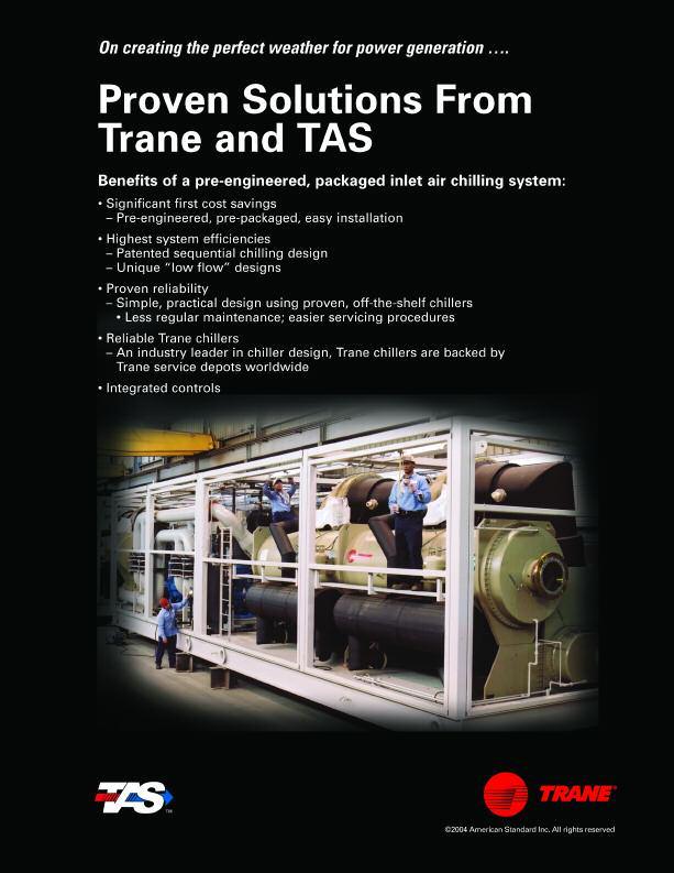
27

28
Gas Turbine Inlet Air Cooling System
 Gas Turbine Inlet Air Cooling System Presented by Bob Omidvar Heavy Duty GT - Effects of Ambient Temp 110% 105% 100% 95% 90% 85% 80% 75% 0 5 10 15 20 25 30 35 40 45 GT Inlet Temp (deg C) Heat rate kj/kwh
Packaged AHR (Advanced Heat Recovery) Systems for Engines, Gas Turbines, & Industrial Waste Heat. Tom Pierson
 Systems for Engines, Gas Turbines, & Industrial Waste Heat. Tom Pierson") Packaged AHR (Advanced Heat Recovery) Systems for Engines, Gas Turbines, & Industrial Waste Heat Tom Pierson Last Field Erected CHP Project- Calpine Clear Lake, TX 1999 Evolution of Packaged Concept 500,000+
Packaged AHR (Advanced Heat Recovery) Systems for Engines, Gas Turbines, & Industrial Waste Heat Tom Pierson Last Field Erected CHP Project- Calpine Clear Lake, TX 1999 Evolution of Packaged Concept 500,000+
Absorption Refrigeration Cycle Turbine Inlet Conditioning. Luke Buntz ARCTIC Engineer Kiewit Power Engineers Co. ARCTIC
 Absorption Refrigeration Cycle Turbine Inlet Conditioning Luke Buntz Engineer Kiewit Power Engineers Co. 1 Overview 2 Generator Output (MW) The Problem Why chill? Increased fuel efficiency (fewer emissions)
Cogeneration. Thermal Chillers. and. .. ASHRAE National Capital Chapter. Arlington, VA 10/10/2012
 Cogeneration and Thermal Chillers.. ASHRAE National Capital Chapter. Arlington, VA 10/10/2012 Agenda Cogeneration Interest and Application Basics Equipment Matching Thermal Chiller Overview Steam Components
Combustion Turbine Inlet Cooling using Direct Evaporative Cooling
 Combustion Turbine Inlet Cooling using Direct Evaporative Cooling By Pat Zeller, Munters Corporation Sponsored by: Turbine Inlet Cooling Association (TICA) August 22, 2012; 1 PM (U.S. Central Time) http://www.meetingzone.com/presenter/default.aspx?partcec=4147918
Turbine Inlet Air Chilling
 Turbine Inlet Air Chilling Stellar Energy Stellar Energy s TIAC solutions integrate proven chilling technology, comprehensive process design and state-ofthe art controls to deliver a TIAC system optimized
Central Utilities at UNL: NU Corp & Development of Thermal Energy Storage (TES) at UNL East Campus
 at UNL East Campus") Central Utilities at UNL: NU Corp & Development of Thermal Energy Storage (TES) at UNL East Campus Big Ten and Friends Mechanical & Energy Conference U of Nebraska-Lincoln October 15, 2012 Before NU Corp
Central Utilities at UNL: NU Corp & Development of Thermal Energy Storage (TES) at UNL East Campus Big Ten and Friends Mechanical & Energy Conference U of Nebraska-Lincoln October 15, 2012 Before NU Corp
Waste Heat Recovery at Compressor Stations
 Waste Heat Recovery at Compressor Stations The path towards novel and high-impact technologies and their implementation Gas Electric Partnership Houston, TX Feb 10-11 2010 Presented by Southwest Research
John S. Andrepont, President The Cool Solutions Company. ECOSTOCK 2006 Absecon, New Jersey, U.S.A. - June 1, 2006
 Practical Developments in Sensible Heat, Diurnal Cool Thermal Energy Storage (TES): Large Applications, Low Temps, Energy Efficiency, and Operating Plus Capital Savings John S. Andrepont, President The
CHP 201: Commercial & Critical Facilities
 CHP 201: Commercial & Critical Facilities Energy Facilities Connections Conference Leavenworth, WA May 8, 2014 Dave Sjoding, Director DOE Northwest CHP Technical Assistance Partnership 1 President s Executive
Union College Combined Cooling, Heat and Power Project
 Union College Combined Cooling, Heat and Power Project Presented by: Mark Donovan, PE Union College, Assistant Director of Utilities Aaron Bolhous, PEng CHA, Project Engineer Agenda Introduction to Union
Application of a cooling tower model for optimizing energy use
 Advances in Fluid Mechanics X 305 Application of a cooling tower model for optimizing energy use G. C. O Mary & D. F. Dyer Department of Mechanical Engineering, Auburn University, USA Abstract The overall
Low temperature cogeneration using waste heat from research reactor as a source for heat pump
 National Centre for Nuclear Research in Poland Low temperature cogeneration using waste heat from research reactor as a source for heat pump Anna Przybyszewska International Atomic Energy Agency 14-16
Chilled Water Plant Redesign
 17 Chilled Water Plant Redesign OVERVIEW The chilled water plant redesign includes the addition of a thermal energy storage system. This allows for economic and operational benefits for the facility by
Absorption Chillers in Commerce
 Absorption Chillers in Commerce Today, absorption chillers are sold for a wide variety of applications. Here s why Changing Electrical Prices The absorption chiller is remarkably flexible, using steam,
Absorption Chillers in Industry
 Absorption Chillers in Industry With deregulation and recent advances, absorption can be the best suited chiller option available. For Robust Performance Look to the Horizon Series of Absorption Chillers
Texas Hospital. Central Plant Redesign. Central Utility Plant SECOND PLACE HEALTH CARE FACILITIES, EXISTING 2013 ASHRAE TECHNOLOGY AWARD CASE STUDIES
 This article was published in ASHRAE Journal, January 2014. Copyright 2014 ASHRAE. Posted at www. ashrae.org. This article may not be copied and/or distributed electronically or in paper form without permission
Performance Evaluation Of Gas Turbine By Reducing The Inlet Air Temperature
 International Journal of Technology Enhancements and Emerging Engineering Research, VOL 1, ISSUE 1 20 Performance Evaluation Of Gas Turbine By Reducing The Inlet Air Temperature V. Gopinath 1, G. Navaneethakrishnan
High efficient peak power on demand. Answers for energy.
 www.siemens.com/energy High efficient peak power on demand POWER-GEN Asia 2011 KLCC, Malaysia, Kuala Lumpur September 27 29, 2011 Authors: Jan Dirk Beiler Siemens AG Energy Sector Fossil Power Generation
Providing free cooling from low temperature waste heat
 Providing free cooling from low temperature waste heat through By Dinesh Gupta Past President ASHRAE India chapter President, Bry-Air Asia A. THE TECHNOLOGY Comparing the adsorption cycle with the refrigeration
BUILDING FOR THE FUTURE
 BUILDING FOR THE FUTURE The following article was published in ASHRAE Journal, September 4. Copyright 4 American Society of Heating, Refrigerating and Air- Conditioning Engineers, Inc. It is presented
Thomas F. Edgar University of Texas-Austin NSF Workshop on Shale Gas Monetization Montgomery, TX, March 27, 2014
 Impact of Shale Gas on Energy Efficiency and Smart Manufacturing Thomas F. Edgar University of Texas-Austin NSF Workshop on Shale Gas Monetization Montgomery, TX, March 27, 2014 1 Outline U.S. energy/environment
CHP Case Studies. Midwest CHP Application Center (MAC) .org (312) University of Illinois at Chicago Energy Resources Center UIC
 .org (312) University of Illinois at Chicago Energy Resources Center UIC") CHP Case Studies Midwest CHP Application Center (MAC) www.chpcentermw.org.org (312)413-5448 University of Illinois at Chicago Energy Resources Center CHP Case Studies Elgin Community College Presbyterian
CHP Case Studies Midwest CHP Application Center (MAC) www.chpcentermw.org.org (312)413-5448 University of Illinois at Chicago Energy Resources Center CHP Case Studies Elgin Community College Presbyterian
CASE STUDY FOR RETROFIT OF TURBINE INLET COOLING IN BATAM, INDONESIA.
 CASE STUDY FOR RETROFIT OF TURBINE INLET COOLING IN BATAM, INDONESIA www.tas.com Introduction About Medco Power About TAS Turbine inlet cooling the impact Indonesia project execution Operating results
Ground-Coupled Heat Pump And Energy Storage
 Ground-Coupled Heat Pump And Energy Storage By Ed Lohrenz, Member ASHRAE; and Sergio Almeida, P.Eng., Member ASHRAE Ground-coupled heat pump (GCHP) systems consume less purchased energy than an HVAC system
Condenser Water Heat Recovery"
 PLEASE MUTE CELL PHONES Condenser Water Heat Recovery" Julian de Bullet ASHRAE Distinguished Lecturer Director of Industry Relations McQuay International 703-395-5054 1 What Is Sustainability? sustainable
CONDENSING TEMPERATURE CONTROL THROUGH ENERGY MANAGEMENT SYSTEM SIMULATON FOR A LARGE OFFICE BUILDING
 CONDENSING TEMPERATURE CONTROL THROUGH ENERGY MANAGEMENT SYSTEM SIMULATON FOR A LARGE OFFICE BUILDING Young-Hoon Kwak 1, Dong-Seok Kong 1, Se-Hwan Cheon 1, Ro-Yeul Kwak 2, and Jung-Ho Huh 3 1 Department
Application of Near-Optimal Tower Control and Free Cooling on the Condenser Water Side for Optimization of Central Cooling Systems
 Purdue University Purdue e-pubs International High Performance Buildings Conference School of Mechanical Engineering 2014 Application of Near-Optimal Tower Control and Free Cooling on the Condenser Water
Chapter Six{ TC "Chapter Six" \l 1 } System Simulation
 Chapter Six{ TC "Chapter Six" \l 1 } System Simulation In the previous chapters models of the components of the cooling cycle and of the power plant were introduced. The TRNSYS model of the power plant
Utilization of Atmospheric Heat Exchangers in LNG Vaporization Processes:
 Utilization of Atmospheric Heat Exchangers in LNG Vaporization Processes: A comparison of systems and methods Tom Dendy SPX Thermal Equipment & Services Rajeev Nanda Technip, USA April 7, 2008 Presented
Assessment of Inlet Cooling to Enhance Output of a Fleet of Gas Turbines
 Proceedings of Industrial Energy Technology Conference IETC 30th, New Orleans, May 6-9, 2008 Assessment of Inlet Cooling to Enhance Output of a Fleet of Gas Turbines Ting Wang Louis Braquet Energy Conversion
ENERGY MANAGEMENT IN A CHILLED WATER PLANT USING THERMAL STORAGE
 ENERGY MANAGEMENT IN A CHILLED WATER PLANT USING THERMAL STORAGE The Tenth International Conference on Thermal Energy Storage ECOSTOCK 2006 Stephane Bilodeau,, PE, Ph.D. sbilodeau@groupeenerstat.com Scope
Modeling and analyzing solar cooling systems in Polysun
 Modeling and analyzing solar cooling systems in Polysun Seyed H. Rezaei (seyed.rezaei@velasolaris.com) 1 Andreas Witzig (andreas.witzig@velasolaris.com) 1 Michael Pfeiffer (michael.pfeiffer@velasolaris.com)
24th World Gas Conference ARGENTINA WOC 5.1: Industrial Utilisation CHP - Sharing on Gas District Cooling (GDC) in Malaysia
 in Malaysia") WOC 5.1: Industrial Utilisation CHP - Sharing on Gas District Cooling (GDC) in Malaysia By Mohd FAIROS Roslan and Mohd ROZI Othman Malaysian Gas Association (MGA) One of the energy solutions using natural
WOC 5.1: Industrial Utilisation CHP - Sharing on Gas District Cooling (GDC) in Malaysia By Mohd FAIROS Roslan and Mohd ROZI Othman Malaysian Gas Association (MGA) One of the energy solutions using natural
Heat Recovery. Integrated CHP Systems Corp.
 Heat Recovery In order to achieve CHP efficiencies of 80% the recovery of waste heat for useful purposes is more significant than the electric efficiency This isn t necessarily in sync with the economics
ENERGY RECOVERY IMPROVEMENT USING ORGANIC RANKINE CYCLE AT COVANTA S HAVERHILL FACILITY
 Proceedings of the 18th Annual North American Waste-to-Energy Conference NAWTEC18 May 11-13, 2010, Orlando, Florida, USA Paper Number: NAWTEC18-3563 ENERGY RECOVERY IMPROVEMENT USING ORGANIC RANKINE CYCLE
ENERGY EFFICIENT THERMAL ENERGY STORAGE FOR DX AIR CONDITIONING
 ENERGY EFFICIENT THERMAL ENERGY STORAGE FOR DX AIR CONDITIONING Paul Kuhlman (pkuhlman@ice-energy.com) Ramachadran Narayanamurthy (ram@ice-energy.com) Ice Energy Inc. 9351 Eastman Park Dr.; Suite B Windsor
District Cooling Sustainable Design. Presented by George Berbari CEO of DC PRO Engineering
 2016 District Cooling Presented by George Berbari CEO of DC PRO Engineering District Cooling Brief History & Future Central Chilled Water plants existed in the Middle East as early as the 1960 s. Few examples
Microturbine CHP for Microgrids Microgrid2017
 Microturbine CHP for Microgrids Microgrid2017 Why Microturbines for Microgrids? Proven: Over 3,000 sites operating in Stand Alone and Dual Mode One Moving Part; Air Bearings Invertor Based Power Electronics
REPORT DOCUMENTATION PAGE
 REPORT DOCUMENTATION PAGE Form Approved OMBNo.0704-018 Public reporting burden for this collection of information is estimated to average 1 hour per response, including the time for reviewing instructions,
Chapter 2.7: Cogeneration
 Chapter 2.7: Cogeneration Part-I: Objective type questions and answers 1. In cogeneration, the system efficiencies can go up to ------ a) 70% b) 80% c) 90% d) 60% 2. Cogeneration is the simultaneous generation
ASSET OPTIMIZATION OF NEW POWER PROJECTS WITH GAS TURBINE INLET AIR COOLING
 ASSET OPTIMIZATION OF NEW POWER PROJECTS WITH GAS TURBINE INLET AIR COOLING Winning Power Plant Projects in the GCC through a Simple and Proven Restructuring of Generation Technology A guide for GT OEM
DUBAL Energy Optimization Absorption Chiller Pilot Project
 DUBAL Energy Optimization Absorption Chiller Pilot Project Global Sustainable Cities Network - 2014 23 January 2014 Tariq Alzarooni Manager: Asset Management: Power and Desalination Innovation in energy-conservation
Performance evaluation of a small-scale polygeneration plant including a desiccant cooling system and an innovative natural gas ICE
 Performance evaluation of a small-scale polygeneration plant including a desiccant cooling system and an innovative natural gas ICE Armando Portoraro Energetics Department Politecnico di Torino (Italy)
IRP 101. Intro to Integrated Resource Planning. Scott Benson Manager, Resource & Transmission Planning. March 23, 2017
 IRP 101 Intro to Integrated Resource Planning Scott Benson Manager, Resource & Transmission Planning March 23, 2017 1 What is an IRP? Definition Integrated resource planning is a process by which a power
University of Illinois Utility Master Plan and Dispatch Model
 University of Illinois Utility Master Plan and Dispatch Model Presented by: Mike Larson, University of Illinois Andy Price, Affiliated Engineers, Inc. B1G & Friends Utility 2017 April, 2017 University
Efficient and Flexible AHAT Gas Turbine System
 Efficient and Flexible AHAT Gas Turbine System Efficient and Flexible AHAT Gas Turbine System 372 Jin ichiro Gotoh, Dr. Eng. Kazuhiko Sato Hidefumi Araki Shinya Marushima, Dr. Eng. OVERVIEW: Hitachi is
Available online at ScienceDirect. Energy Procedia 48 (2014 )
") Available online at www.sciencedirect.com ScienceDirect Energy Procedia 48 (2014 ) 1181 1187 SHC 2013, International Conference on Solar Heating and Cooling for Buildings and Industry September 23-25,
Available online at www.sciencedirect.com ScienceDirect Energy Procedia 48 (2014 ) 1181 1187 SHC 2013, International Conference on Solar Heating and Cooling for Buildings and Industry September 23-25,
Combined Heat and Power (CHP)
") February 3-4, 2009 Net Zero Energy Installation and Deployed Bases Workshop Colorado Springs, CO Session III: Power & Energy Architecture for NZE Cliff Haefke Energy Resources Center / University of Illinois
February 3-4, 2009 Net Zero Energy Installation and Deployed Bases Workshop Colorado Springs, CO Session III: Power & Energy Architecture for NZE Cliff Haefke Energy Resources Center / University of Illinois
SYMPOSIUM ON INDUSTRIAL APPLICATIONS OF GAS TURBINES
 20TH SYMPOSIUM ON INDUSTRIAL APPLICATIONS OF GAS TURBINES Inlet Fogging and Overspray Impact on Gas Turbine Life and Performance by Klaus Brun / Southwest Research Institute Rainer Kurz / Solar Turbines
TECHNICAL PAPER ABSTRACT
 Title: Authors: Energy Efficiency Drives Environmental Efficiency Case Study of the Thermal Energy Corp. Energy Center at Texas Medical Center in Houston Steve Swinson, PE, Thermal Energy Corp. Robynn
Value of Air Source Heat Pumps in Light of Variable Energy Prices. Jeff Haase. Energy Design Conference February 27, 2013
 Value of Air Source Heat Pumps in Light of Variable Energy Prices Jeff Haase Energy Design Conference February 27, 2013 Agenda Overview of Air Source Heat Pump Technologies History, General Comparison
Title of presentation
 Title of presentation Reducing energy usage through the implementation of an ice cooling system Jan du Plessis, Senior Consultant, Gold Fields Ltd, Gauteng, South Africa MRA Safety in Deep Mining 2008,
Comparison of Different Gas Turbine Inlet Air Cooling Methods
 Comparison of Different Gas Turbine Inlet Air Cooling Methods Ana Paula P. dos Santos, Claudia R. Andrade and Edson L. Zaparoli International Science Index, Aerospace and Mechanical Engineering waset.org/publication/2686
Draft Results Capital Cost and Performance of New Entrant Peaking Unit
 Draft Results Capital Cost and Performance of New Entrant Peaking Unit Presentation to Christopher D. Ungate, Senior Consultant 1 Scope of New Entrant Peaking Unit Assumptions Peaking Unit Technology:
Organic Rankine Cycle Technology
 Power Systems Pratt & Whitney Power Systems Organic Rankine Cycle Technology TM It s in our power. Pratt & Whitney Organic Rankine Cycle Technology Quality High-volume components produced to strict tolerances
COGENERATION SYSTEM INTRODUCTION
 COGENERATION SYSTEM INTRODUCTION New Mexico State University currently provides a number of necessary utilities to the main campus such as electrical power, steam, and chilled water among others. It was
Thermal Energy Storage
 This article was published in ASHRAE Journal, June 2013. Copyright 2013 ASHRAE. Posted at www.ashrae.org. This article may not be copied and/or distributed electronically or in paper form without permission
UNIQUE DESIGN CHALLENGES IN THE AUX SABLE NGL RECOVERY PLANT
 UNIQUE DESIGN CHALLENGES IN THE AUX SABLE NGL RECOVERY PLANT Presented at the 81 st Annual Convention of the Gas Processors Association March 11, 2002 Dallas, Texas Joe T. Lynch, P.E. Ortloff Engineers,
The Present and Future of Refrigeration, Power Generation and Energy Storage. R.Z. Wang Shanghai Jiao Tong University
 The Present and Future of Refrigeration, Power Generation and Energy Storage R.Z. Wang Shanghai Jiao Tong University Contents Introduction Refrigeration Power generation Energy storage Discussions Introduction
District Energy Combined Heat and Power as a Resource
 District Energy Combined Heat and Power as a Resource Cliff Braddock Director Energy Business Development Austin Energy 512-322-6302 Cliff.braddock@austinenergy.com 2007 ACEEE Conference on Energy Efficiency
Section 3 Characteristics of Credits Types of units. Economic Noneconomic Generation.
 Section 3 Operating Reserve Operating Reserve Day-ahead and real-time operating reserve credits are paid to market participants under specified conditions in order to ensure that resources are not required
Presented by: Mike Buter Operations Manager
 Coffee, Conversation and CHP Presented by: Mike Buter Operations Manager PRESENTATION OUTLINE APS Energy Services Company, Inc. Traditional Energy Systems Alternative Energy Systems Pros and Cons Project
Chapter 8. Vapor Power Systems
 Chapter 8 Vapor Power Systems Introducing Power Generation To meet our national power needs there are challenges related to Declining economically recoverable supplies of nonrenewable energy resources.
Grand Composite Curve Module 04 Lecture 12
 Module 04: Targeting Lecture 12: Grand Composite Curve While composite curves provide overall energy targets, these do not indicate the amount of energy that should be supplied at different temperature
Gas Power Systems Energy Efficient CHP Solutions for Commercial and Large-scale Residential Buildings
 Gas Power Systems Energy Efficient CHP Solutions for Commercial and Large-scale Residential Buildings Los Angeles, 2009 March 10 John Ferraro Building Stefan Kohler - MTU Onsite Energy GmbH Page 2 / 3/16/2009
OPERATING PARAMETERS Reliable Means to Continuously Monitor Facility Performance
 OPERATING PARAMETERS Reliable Means to Continuously Monitor Facility Performance RICHARD SCHERRER Ogden Martin Systems, Inc. Fairfield, New Jersey ABSTRACT Energy sales are a major source of revenues for
Sub Wet-Bulb Evaporative Chiller
 Emerging Technologies Sub Wet-Bulb Evaporative Chiller Prepared by: Emerging Products Customer Service Southern California Edison June 2015 Acknowledgments Southern California Edison s Emerging Products
Economics of Cogeneration
 The following article was published in ASHRAE Journal, October 2002. Copyright 2002 American Society of Heating, Refrigerating and Air-Conditioning Engineers, Inc. It is presented for educational purposes
Large University Central Chiller Plant Design Considerations
 Carrier Engineering Newsletter Volume 5, Issue 3 Large University Central Chiller Plant Design Considerations Large campus chilled water plants have unique constraints and need careful evaluation for successful
Packaged Refrigerant Based Energy Storage (RBES) Air Conditioning System
 Air Conditioning System") Packaged Refrigerant Based Energy Storage (RBES) Air Conditioning System Ram Narayanamurthy Ice Energy, Inc. this technology provides some of the largest opportunities we have right now to address the
Packaged Refrigerant Based Energy Storage (RBES) Air Conditioning System Ram Narayanamurthy Ice Energy, Inc. this technology provides some of the largest opportunities we have right now to address the
Sea Water Heat Pump Project
 Sea Water Heat Pump Project Alaska SeaLife Center, Seward, AK Presenter: Andy Baker, PE, YourCleanEnergy LLC JCOS Forum Juneau Library April 11, 2013 This powerpoint Copyright 2013 by YourCleanEnergy LLC,
Plant Utilities and Energy Efficiency CH505
 Plant Utilities and Energy Efficiency CH505 Teaching Scheme Course code CH505 Course Name Plant Utilities and Energy Efficiency Teaching scheme L T P Credit 3 0 0 3 Process Process is simply a method by
Great Ocean Rd Ice Creamery
 Great Ocean Rd Ice Creamery BCA Section J - JV3 Compliance Report Revision: 01 Job No: 2171 Date: 7 July 2015 ADP Consulting Pty Ltd Level 10, 10 Queens Rd, Melbourne Vic 3004 www.adpconsulting.com.au
7. Electrical Facility Ratings
 7. Electrical Facility Ratings 7.1 Accredited Net Generating Capacity This Section shall be used to determine the annual and seasonal accredited net generating capacity of generators in calculating the
Over 3 decades, the company has helped customers to be competitive and earn community goodwill by :
 Company Overview Over 3 decades, the company has helped customers to be competitive and earn community goodwill by : Maximizing energy efficiency and slashing operating costs Minimizing waste Recovering
Design and development of a residential gas-fired heat pump
 Design and development of a residential gas-fired heat pump Edward A Vineyard a*, Ahmad Abu-Heiba a, Isaac Mahderekal b a Oak Ridge National Laboratory, P.O. Box 2008, MS 6070, Oak Ridge, TN, 37831, USA
TransPacific Energy Advantage: Case Studies
 TransPacific Energy Advantage: Case Studies Typical Power Plant TPE-ORC 0.60 KWh ORC 2.3 KWh LP steam 0.35 KWh 30% (maximum) 2.05 KWh CHP Typical Power Generated 1.1 KWh Typical Power Wasted 2.31 KWh Typical
Kawasaki Gas Turbines-Americas Gas Turbines Power Generation Technology & Applications
 Kawasaki Gas Turbines-Americas Gas Turbines Power Generation Technology & Applications Gas Turbine (GT) Technology Overview Gas Turbine Theory GT - Centrifugal Compressor FUEL INLET COMBUSTION CHAMBER
WFM. Big Box Retail CCHP
 WFM Big Box Retail CCHP Integrating CHP with DG Big Box Store CCHP 11/14/14 Washington DC Douglas Davis Director Broad USA Hackensack NJ 201 951 5713 davis@broadusa.com AGENDA Modern Absorption/CCHP Technology
89m. 15% Temperature Control revenue 40% Why choose Aggreko?
 EVENTS KEY FACTS Why choose Aggreko? Safety culture and record Unrivaled experience and track record Largest dedicated global events fleet Design capability and design software Innovative & sustainable
Gas vs. Diesel Generator Sets Performance Cost & Application Differences
 Gas vs. Diesel Generator Sets Performance Cost & Application Differences Page 1 Agenda Introduction Distributed Energy Products Diesel, Gas and Turbine generator sets How Engines Accept Loads Gas Product
Optimisation and Cost Analysis of a Lithium Bromide Absorption Solar Cooling System
 Optimisation and Cost Analysis of a Lithium Bromide Absorption Solar Cooling System Georgios A. Florides and Soteris A. Kalogirou Mechanical Engineering Department, Higher Technical Institute, Nicosia,
DESIGN ANALYSIS OF A REFRIGERATED WAREHOUSE USING LNG COLD ENERGY
 , Volume 4, Number 1, p.14-23, 2003 DESIGN ANALYSIS OF A REFRIGERATED WAREHOUSE USING LNG COLD ENERGY K.H. Yang and S.C. Wu Mechanical Engineering Department, National Sun Yat-Sen University, Kaohsiung,
MOLECULAR GATE TECHNOLOGY FOR (SMALLER SCALE) LNG PRETREATMENT
 LNG PRETREATMENT") MOLECULAR GATE TECHNOLOGY FOR (SMALLER SCALE) LNG PRETREATMENT Presented at the 2010 Gas Processors 89 th Annual Convention Austin, TX March, 2010 Michael Mitariten, P.E. Guild Associates, Inc. Dublin,
MOLECULAR GATE TECHNOLOGY FOR (SMALLER SCALE) LNG PRETREATMENT Presented at the 2010 Gas Processors 89 th Annual Convention Austin, TX March, 2010 Michael Mitariten, P.E. Guild Associates, Inc. Dublin,
BEYOND O&M. Shawn Maurer SEDAC Building Energy Specialist. Smart Energy Design Assistance Center (SEDAC), University of Illinois at Urbana Champaign
, University of Illinois at Urbana Champaign") BEYOND O&M Shawn Maurer SEDAC Building Specialist Smart Design Assistance Center (SEDAC), University of Illinois at Urbana Champaign PRESENTATION OVERVIEW and Take away: Regular costs less over the long
BEYOND O&M Shawn Maurer SEDAC Building Specialist Smart Design Assistance Center (SEDAC), University of Illinois at Urbana Champaign PRESENTATION OVERVIEW and Take away: Regular costs less over the long
FMI ENERGY CONFERENCE. Orlando September 2008
 FMI ENERGY CONFERENCE Orlando September 2008 FUEL CELL ORIGINS Sir William Grove invented the fuel cell in 1839 Demonstrated that reaction was reversible Fuel cell term introduced by Ludwig Mond and Charles
Intelligent Process Cooling Technology Saves on Water and Energy, Improves Productivity
 Intelligent Process Cooling Technology Saves on Water and Energy, Improves Productivity Presented at the Society of Plastics Engineer s ANTEC, May 1-5, 2011 in Boston, MA, USA Lou Zavala, National Sales
Chapter 3.7: Cooling Towers
 Part-I: Objective type questions and answers Chapter 3.7: Cooling Towers 1. The type of cooling towers with maximum heat transfer between air to water is. a) Natural draft b) Mechanical draft c) Both a
ASHRAE 2004, ANAHEIM WINTER MEETING
 Synopsis VENUE ASHRAE 2004, ANAHEIM WINTER MEETING TITLE EUTECTIC (PCM) BASED HEAT REJECTION THERMAL ENERGY STORAGE SYSTEMS AUTHORS Zafer URE M.Sc., C.Eng., MCIBSE, MASHRAE, M.Inst.R, MIIR Environmental
Ground Source Heat Pump System Performance: Measuring the COP
 Ground Source Heat Pump System Performance: Measuring the COP Ground Energy Support, LLC June 2013 1 Introduction This article is the second in a three-part series prepared by Ground Energy Support LLC
Galileo Research. Distributed Generation
 Galileo Research Distributed Generation 2001-2013 Distributed, or small generation units, typically less than 30MWs, strategically located near consumers and load centers can provide benefits to customers
LIBRARY ENERGY WALK- THROUGH. Andy Robinson, Training and Education, SEDAC
 LIBRARY ENERGY WALK- THROUGH Andy Robinson, Training and Education, SEDAC ILLINOIS ENERGY NOW University of Illinois 360 Energy Group 2 WHAT WE DO SEDAC Free Services Outreach and Training Energy Assistance
CHILLED WATER DISTRIBUTION SYSTEM
 Campus-Wide System: A campus-wide central chilled water system has been developed in recent years and is being expanded to serve additional cooling loads as need arises and opportunity affords. This system
Doc. CEN/TC 228 N541 CEN/TC 228
 Doc. CEN/TC 228 N541 CEN/TC 228 Date: 2006-08 CEN/TC 228 WI 026 CEN/TC 228 Secretariat: DS Heating systems in buildings Method for calculation of system energy requirements and system efficiencies Part
The answer is... yes!
 The answer is... yes! TURN YOUR HEAT INTO ELECTRICITY NO FUEL, ZERO EMISSION Can plain machines save costs and energy at the same time as saving our beautiful planet? ENERGY CONCERN Today s society is
Marc de Croisset FBR CAPITAL MARKETS & CO. Coal-to-Gas Switching: Distilling the Issue
 Marc de Croisset. 646.885.5423. mdecroisset@fbr.com FBR CAPITAL MARKETS & CO. Coal-to-Gas Switching: Distilling the Issue September 20, 2012 Disclosures Important disclosures can be found at the end of
Equipment Design. Detailed Plant Conceptual Design. Version 9.0
 Equipment Design Version 9.0 Detailed Plant Conceptual Design SOAPP CT sizes all major plant equipment, based on your Project Input, the process configuration derived from this input, and the results of
PAPER NUMBER 64-GTP-16 S. T. ROBINSON J. W. GLESSNER. Solar, A Division of International Harvester Company, San Diego, Calif. Mems. ASME.
 PAPER NUMBER 4-GTP-1 Copyright 194 by ASME AN ASME PUBLICATION Total Turbine Energy in Refrigeration Cycles S. T. ROBINSON J. W. GLESSNER Solar, A Division of International Harvester Company, San Diego,
Heating the University of Glasgow with river sourced heat pumps. Adam McConkey Andrew Poon-King Zhibin Yu
 Heating the University of Glasgow with river sourced heat pumps Adam McConkey Andrew Poon-King Zhibin Yu Opportunity - Reduce Glasgow University s 1.9 m gas bill - The University is set to upgrade its