DISPLACEMENT VENTILATION
|
|
|
- Ruth Oliver
- 5 years ago
- Views:
Transcription


1 clever creative comfort DISPLACEMENT VENTILATION A p p l i c a t i o n G u i d e
2 Application Guide3 Introduction to 3 Air Change Effectiveness3 Typical Applications4 Contaminant Removal4 Benefits & Limitations4 Energy Considerations4 Outlet Characteristics5 The Adjacent Zone 5 Outlet Choices5 Heat Sources & Convective Flows6 Space Temperature Gradients & Airflow Rates6 Air Pattern Projection6 Methods of Evaluation7 Supply Air Connections7 Acoustical Performance7 Theory & Governing Equations7 Design Procedure for 9 Design Examples10 References16


3 Design & Application Guide Buildings come in all shapes and sizes and are designed for any number of purposes In order to create healthy and productive environments, air distribution systems must be selected that best meet the goals of designers There are a wide range of choices available, but often one system can be identified as the best solution in terms of cost, comfort and energy The purpose of this guide is to explain how displacement ventilation works, describe recommended applications and provide engineering guidance to the system designer INTRODUCTION TO DISPLACEMENT VENTILATION In order to understand the advantages and limitations of displacement ventilation, it s important to understand the differences between conventional mixed air distribution and fully-stratified air distribution In mixed air distribution, hot or cold supply air is delivered at relatively high velocity from ceiling-mounted diffusers When ceiling diffusers are properly selected and positioned, this high velocity air doesn t result in occupant discomfort because it is delivered outside the occupied zone The purpose of the high velocity supply is to create low velocity room air motion through entrainment Ideally, this air motion will thoroughly mix the supply air with the room air resulting in uniform temperature and contaminant levels throughout the occupied zone Internal heat loads and contaminants are eventually picked up and carried away by the return air Figure 1 Mixed Air System In fully-stratified air distribution, cool supply air is typically delivered at reduced velocity from low sidewall diffusers The supply air is always cooler than the room air, so it quickly drops to the floor and moves slowly across the room When this slow moving air mass encounters a heat load, it rises and carries the heat and pollutants towards the ceiling A layer of warm air forms above the occupied zone due to natural buoyancy Internal heat loads and contaminants are carried away by the return air Figure 2 Fully-Stratified System The main differences between these systems are: Mixed air distribution Suitable for both heating and cooling with a supply temperature range of 38 to 90 F Air is supplied to the unoccupied zone at relatively high velocity Minimizes temperature variations throughout the space Creates uniform contaminant concentration throughout the zone Fully-stratified air distribution Suitable for cooling only with a supply temperature range of 62 to 70 F Air is supplied directly to the occupied zone at low velocity Takes advantage of natural air buoyancy to divide the zone into two regions Heat and pollutants rise into the upper unoccupied zone Contaminant concentration is greatly reduced in the lower occupied zone AIR CHANGE EFFECTIVENESS ASHRAE Standard Ventilation for Acceptable Indoor Air Quality assigns a zone air distribution effectiveness value (E z ) of 10 for conventional mixed air systems and 12 for fully-stratified systems (Table 6-2) This means that fully-stratified systems are 20% more effective than the best mixed air systems and can provide the same level of ventilation with a 167% reduction in air volume This reduces the amount of outdoor air necessary to meet ventilation requirements 3


4 TYPICAL APPLICATIONS Ideal applications for displacement ventilation often involve large open spaces with tall ceilings These include but are not limited to: Theaters and performance halls Meeting rooms and lecture halls Restaurants and cafeterias Hotel lobbies and atriums Shopping malls Gymnasiums Casinos Museums and exhibit halls Classrooms Airport terminals and train stations CONTAMINANT REMOVAL Displacement ventilation can be a very effective strategy for removing contaminants from room air, because fullystratified systems take advantage of the fact that airborne pollutants are generally lighter than air The natural buoyancy of tobacco smoke and human respiration allow these pollutants to rise above the breathing zone in plumes to the upper zone that forms below the ceiling This upward migration of pollutants effectively increases concentrations in the unoccupied upper zone while reducing concentrations in the breathing zone Figure 4 Contaminant Distribution in a Fully-Stratified System BENEFITS AND LIMITATIONS Typical benefits of displacement ventilation include: Improved removal of airborne contaminants Greatly reduced energy requirements to cool occupied spaces in mild climates Reduced ventilation air requirement due to increased air distribution effectiveness Very low diffuser noise levels Reduced comfort complaints due to drafts Although displacement ventilation is well-suited for a wide variety of applications, the following spaces may be better served by mixed air systems: Spaces with ceiling heights lower than 9 ft Spaces with occupied zone heat loads in excess of 30 Btu/hr-ft 2 Spaces furnished with cubicles or other partitions Spaces with ceiling heights lower than 10 ft that may be subject to significant room air disturbances Applications involving contaminants that are heavier and/or colder than room air in the occupied zone Figure 3 Contaminant Distribution in a Mixed Air System A couple of important considerations: Displacement ventilation is not recommended for spaces where hazardous chemical spills could occur In the event of a spill, a displacement ventilation system is likely to cause noxious fumes to be drawn from the floor and brought up to the breathing level, thereby increasing the possible hazard to occupants In rare situations where contaminants are heavier than air, accommodations should be made to allow some portion of the room air to be extracted at a lower level ENERGY CONSIDERATIONS Displacement ventilation can reduce energy use in several ways: Increased economizer hours due to increased supply temperatures in comparison to conventional mixed air systems Chiller efficiency increases due to lesser dehumidification at higher water supply temperatures 4


5 OUTLET CHARACTERISTICS Displacement ventilation requires outlets that supply air at extremely low velocities, (typically fpm) These outlets are typically located low on a sidewall or at the base of a column The low average face velocity generally results in rather large diffuser panels Since the outlets are located adjacent to the occupied zone and within easy reach of room occupants, they have the following special requirements: Should be elevated above the floor to prevent damage from cleaning equipment Construction and finishes must be rugged enough to prevent damage through accidental or intentional occupant contact Should provide a concealed and tamperproof means of air pattern adjustment Face panel must be removable for cleaning and adjustment of air pattern controllers Figure 6 Standard Air Patterns THE ADJACENT ZONE The area immediately adjacent to a displacement ventilation outlet is known as the adjacent zone This is any area in the occupied zone where local air velocities exceed 50 fpm at a height 1 in above the floor Although this clear zone can often be in an aisle or corridor without creating potential comfort problems, stationary occupants should never be located within the adjacent zone Cool air that drops from a sidewall diffuser and travels across the floor can easily be sensed by stationary occupants at the ankle level Figure 7 Adjusted Air Patterns professionals for successful project integration Generally speaking, displacement diffusers can be ducted from above or below or plenum-supplied Figure 5 The Adjacent Zone It is important to note that all Titus displacement ventilation diffusers are supplied with adjustable air pattern controllers as standard equipment The ability to adjust the shape of the air pattern and the adjacent zone can be of great benefit when dealing with furniture, occupants and obstructions especially in smaller spaces All Titus displacement diffusers include: Adjustable air pattern controllers Air balancing tap Removable face plate All metal construction (galvanized steel and aluminum) Standard #26 white powdercoat finish Optional telescoping duct cover (not applicable to DVR1) Optional 2-3/4 or 4 inch mounting base (not applicable to DVR1) OUTLET CHOICES Displacement ventilation diffusers are available in a wide range of styles and sizes Unlike conventional ceiling diffusers, the size and placement of displacement ventilation diffusers require early coordination with architectural 5

6 Stratification level Supply Figure 8 Heat Plume Convection plume HEAT SOURCES AND CONVECTIVE FLOWS The flow of convective heat is essential in establishing a fully-stratified system As heat moves from warmer surfaces to the cooler surrounding air, the buoyancy of the air increases and the heat rises to create stratification in the occupied zone This upward air motion driven by convection also results in room air entrainment that results in a larger heat plume Although radiant heat sources do not directly affect these convective heat plumes, they may increase plume formation by increasing surface temperatures of heat sources Return Upper zone Lower zone 0 Heat/contaminant source Temperature, F Setpoint Stratification AIR PATTERN PROJECTION Although displacement ventilation is typically supplied from a low sidewall, the resulting room pattern is very different from a conventional sidewall grille Because the supply air is cooler than the room air and is discharging at low velocity, it immediately drops to the floor The air moves across the floor in a thin layer typically no more than 6-8 inches high The diagrams above show why displacement ventilation is only recommended for cooling applications The characteristics of individual convective heat plumes may be influenced by each of the following: Size and shape of heat source Amount of heat available Air motion surrounding heat source Temperature gradient in the space 6 Convective heat plumes will continue to rise until they reach a room level of equal temperature SPACE TEMPERATURE GRADIENTS AND AIRFLOW RATES Displacement ventilation diffusers supply conditioned air at higher cooling temperatures (typically 62 to 70 F) and lower discharge velocities (less than 70 fpm) than ceiling diffusers Since the supply air is always cooler than the room air, it can be said to cascade from the diffuser face to the floor The negative buoyancy of the cooler air causes it to move at the floor level until it reaches a source of convective heat As the supply air warms, its buoyancy increases to create a heat plume that rises to the upper mixed zone below the ceiling The distance from the floor to the upper mixed zone is known as the shift height Since the design goal of a displacement ventilation system is to create temperature stratification throughout the occupied zone, it is critical that the shift height is greater than height of the occupied zone Lower shift heights may be acceptable in situations where all occupants are seated Figure 9 Discharge Air Patterns This air pattern tends to stretch out and cover the entire room, even if the room shape is irregular Obstructions such as partitions or furniture resting directly on the floor can result in coverage gaps, but the air pattern will rejoin itself much like fluid passing around an object Displacement diffusers can typically provide coverage into a room that is up to six times the length of the adjacent zone Internal heat load concentrations actually help to extend the projection of a displacement system by drawing the air across the room Large rooms can be supplied from the side walls so long as the distance from the diffuser face to the furthest projection is no more than 30 ft When room dimensions exceed 30 ft in length or width, it is best to place displacement diffusers on more than one wall By placing diffusers on opposing walls, rooms up to 60 ft can be supplied from side walls Another solution for large rooms is to place 360-degree diffusers throughout the interior space

7 METHODS OF EVALUATION A successful displacement ventilation design should provide a supply airflow rate to meet the thermal gradient profile of an occupied space in accordance with ASHRAE comfort guidelines ASHRAE Standard Thermal Environmental Conditions for Human Occupancy recommends that vertical temperature differential between a seated occupant s ankle and head regions (roughly 4 to 43 in) should be no more than 54 F to deliver acceptable comfort to 95% or more of the occupants For a stationary standing person same guideline would apply over an elevation range of 4 to 67 in low velocity and therefore do not generate audible noise The catalog sound performance rating of a displacement diffuser is usually expressed in terms of a noise criteria (NC) level based upon a typical space with room absorption of 10 db in each octave band per ASHRAE Standard (Appendix D) While this typical space effect has been used for many years to estimate the sound level of a diffuser serving a small office, this certainly isn t the typical environment in which displacement ventilation is employed Since we are often dealing with much larger spaces and taller ceilings, a different method must be employed to better estimate sound levels A space effect for each octave band can be calculated based upon the size of the room and the distance between the source and observer using the following equation per AHRI Standard : Figure 10 Maximum Temperature Differentials for Acceptable Thermal Comfort SUPPLY AIR CONNECTIONS Displacement ventilation diffusers are usually supplied by ductwork and they can be supplied from either above or below Optional telescoping duct covers are available to hide otherwise visible supply ductwork for a clean finished appearance Optional mounting bases (2-3/4 or 4 inch) are recommended to prevent possible damage due to traffic and floor cleaning equipment These mounting bases are also recommended to simplify installation when air will be supplied from below It is also possible to supply displacement ventilation diffusers from a pressurized plenum Care must be taken to insure that the supply plenum is tightly sealed In a properly designed supply plenum, pressures should be equal throughout and balancing dampers should not be required ACOUSTICAL PERFORMANCE Like any building space, those supplied by displacement ventilation create an acoustical environment with contributions from air handlers, terminal units, diffusers and structure-borne sound Properly sized and selected displacement ventilation diffusers are rarely the cause of noise complaints because they operate at low pressure and Space Effect = log (ft) 5 log (ft 3 ) 3 log (Hz) ft = Distance between the source and observer ft 3 = Room volume Hz = Octave band center frequency When considering sound contributions from multiple diffusers, we can logarithmically add or multiply, but this is typically unnecessary In large spaces, diffusers are rarely close enough together to contribute to the overall room sound level As a general rule for smaller spaces, it is advisable to select diffusers for an NC level that is 10 points lower than the desired room sound level This has the effect of masking the sound contribution of the diffusers in the background sound level For larger spaces, the NC level of the diffuser is less critical because the room effect is so much greater DISPLACEMENT VENTILATION THEORY AND GOVERNING EQUATIONS The following material is based on ASHRAE research project RP-949 that resulted in the ASHRAE publication System Performance Evaluation and Design Guidelines for (2003) This summary is intended to briefly explain the theory behind displacement ventilation For a more detailed explanation including the derivation of each equation, the original publication is highly recommended The design air volume supplied by a displacement ventilation system must be capable of meeting both the cooling and minimum ventilation requirements for a given space In order to determine the cooling design air volume, the type, location and magnitude of all heat loads must be identified These loads can be classified as: Heat generated by occupants, desk lamps and office equipment, Q oe (Btu/h) Heat generated by overhead lighting, Q l (Btu/h) Heat from the exterior wall and window surfaces including transmitted solar radiation, Q ex (Btu/h) 7
8 A weighting factor must be applied to each of these loads to properly approximate the effect of each type of load entering the region between the head and the feet of a seated occupant Based on ASHRAE research, these weighting factors are: Occupants, desk lamps and office equipment, а oe = 0295 Overhead lighting, а l = 0132 Exterior wall and window surfaces including transmitted solar radiation, а ex = 0185 The heat transfer to the region of interest can therefore be calculated by the following equation: T hf ρc p V = а oe Q oe + а l Q l + а ex Q ex T hf = temperature differential between the head and foot level of occupant ( F) ρ = air density under standard conditions (lb/ft 3 ) C p = specific heat of air at constant pressure (Btu/lb- F) V = supply flow rate (ft 3 /h) Substituting the ventilation rate, n, into the equation yields: = (0295Q oe Q l Q ex )/( T hf ρc p ) With the following assumptions: T hf = 36 F (for a seated occupant) ρ = 0075 lb/ft 2 C p = 024 Btu/lb- F This equation can be simplified to: = 0076Q oe Q l Q ex This equation is very useful for typical applications involving seated occupants The required ventilation rate can be determined by consulting ASHRAE Standard This standard provides recommended ventilation rates for various room occupancies and applications (Table 6-1) These recommendations involve the minimum ventilation rates in the breathing zone based upon both occupant density and floor area 8 Since: V = nha n = the required air change rate (ach) H = space height (ft) A = floor area (ft 2 ) The heat transfer equation can be simplified to: T hf = (а oe Q oe + а l Q l + а ex Q ex ) / (ρc p nha) ASHRAE Standard recommends that for good thermal comfort the temperature difference between the head and foot level of a standing person should not exceed 54 F In a stratification zone, assume that the temperature gradient will be less than 1 F/ft Since the vertical temperature gradient between a seated person s head (36 ft) and a standing person s head (56 ft) is generally less than that between the ankle level (03 ft) and seated person s head (36 ft), any design that meets the seated recommendations should also be suitable for a standing person The same equation can be used to calculate the required ventilation rate: n = (а oe Q oe + а l Q l + а ex Q ex ) / ( T hf ρc p HA) The cooling air volume (cfm),, for a typical office environment can then be calculated using the following equation: = nah/60 The breathing zone outdoor airflow (cfm),, can be calculated using the following equation: = (R p x P z ) + (R a x A z ) R p = people outdoor air rate from Table 6-1 (cfm/person) P z = zone population (#) R a = area outdoor air rate from Table 6-1 (cfm/ft 2 ) A z = zone floor area (ft 2 ) ASHRAE Standard also defines air change effectiveness (E z ) of various types of air distribution systems (Table 6-2) While the best mixed air system with ceiling diffusers can only achieve a rating of 10, displacement ventilation systems achieve a 12 rating This means that a displacement ventilation system can meet ventilation requirements with 167% less air volume than a mixed air system Be aware that local code requirements may be more stringent than the minimum standards recommended by ASHRAE and may not differentiate between system types and air change effectiveness The zone outdoor airflow requirement (cfm),, can be calculated as: = / E z E z = air change effectiveness from Table 6-2 The supply air volume (cfm), V, will be larger of either the cooling air volume (cfm),, or the zone outdoor airflow requirement (cfm), Be aware that if a dedicated outdoor air system (DOAS) is employed, then supply air volume, V, would consist of 100% outdoor air If return air is being
9 mixed with outdoor air, supply air volume, V, must contain enough outdoor air to meet the zone outdoor requirement, The supply air temperature,, is always cooler than the room temperature, p, and can be calculated by based on the air temperature at the floor level, T f T f = p - T hf And: = T f θ f / (60ρC p V) θ f = dimensionless temperature calculated by Mundt s formula (1992) = total cooling load in space (Btu/h) V = supply air volume (cfm) θ f = 1 / ((60VρC p / A)((1/α r ) + (1/α cf )) + 1) α r = radiant heat transfer from ceiling to floor (Btu/h-ft 2 - F) α cf = convective heat transfer from floor surface to the room air (Btu/h-ft 2 - F) Assuming that heat transfer coefficients α r and α cf are equal to 09 Btu/(h-ft 2 - F) and that T hf should be less than 36BF for a seated occupant, this equation can then be simplified to: = p 36 ((A )/(259V AV)) internal heat loads greater than 30 Btu/ft 2 / A 30 Btu/ft 2 A = L x W A = floor area (ft 2 ) L = room length (ft) W = room width (ft) Step 3 Calculate the Cooling Air Volume The cooling air volume,, can be determined from heat loads with weighting factors applied: = 0076Q oe Q l Q ex Step 4 Calculate the Zone Outdoor Airflow for Acceptable Indoor Air Quality The zone outdoor airflow requirement (cfm),, and the breathing zone outdoor airflow (cfm),, can be determined from ASHRAE Standard 621 (Tables 6-1 and 6-2) and the following equations: = (R p x P z ) + (R a x A z ) R p = people outdoor air rate from Table 6-1 (cfm/person) P z = zone population (#) R a = area outdoor air rate from Table 6-1 (cfm/ft 2 ) A z = zone floor area (ft 2 ) The exhaust air temperature, = / E z = + (( )/(108V)) DESIGN PROCEDURE FOR DISPLACEMENT VENTILATION The following design procedure is patterned on that provided in an ASHRAE publication entitled System Performance and Design Guidelines for Displacement Ventilation (2003) It was developed based upon the finding of ASHRAE Research Project RP-949 Step 1 Calculate the Total Cooling Load The total cooling load,, is the sum of the heat loads: = Q oe + Q l + Q ex Q oe = Heat generated by occupants, desk lamps and office equipment (Btu/h) Q l = Heat generated by overhead lighting (Btu/h) Q ex = Heat from the exterior wall and window surfaces including transmitted solar radiation (Btu/h) E z = air change effectiveness from Table 6-2 = 12 Step 5 Determine the Supply Air Volume The supply air volume, V, will be larger of either the cooling air volume,, or the zone outdoor airflow requirement, Step 6 Calculate the Supply Air Temperature The supply air temperature, = p 36 ((A )/(259V AV)) p = room temperature ( F) Step 7 Calculate the Exhaust Air Temperature The exhaust air temperature, = + (( )/(108V)) Step 8 Select Supply Diffuser(s) Step 2 Check for Excessive Heat Load Displacement ventilation is generally not recommended for 9
10 DESIGN EXAMPLE - PRIVATE PERIMETER OFFICE This a small private office measuring 12 ft by 10 ft by 9 ft (L x W x H) The office is equipped with a computer, a monitor, a small printer and a desk lamp The 12 ft long wall includes exterior glass The room will be supplied by a dedicated outdoor air system (DOAS) Assume: Occupancy = 1 Load per person = 250 Btu/h Overhead lighting load = 2 watts/ft 2 = 6826 Btu/h-ft 2 Computer load = 65 watts = 222 Btu/h Monitor load = 30 watts = 102 Btu/h Small printer load = 30 watts = 102 Btu/h Desk lamp load = 40 watts = 137 Btu/h Solar and glass load = 40 Btu/h-ft 2 Step 1 Calculate the Total Cooling Load = Q oe + Q l + Q ex Q oe = Heat generated by occupants, desk lamps and office equipment (Btu/h) Q l = Heat generated by overhead lighting (Btu/h) Q ex = Heat from the exterior wall and window surfaces including transmitted solar radiation (Btu/h) breathing zone outdoor airflow (cfm),, can be determined from ASHRAE Standard 621 (Tables 6-1 and 6-2) and the following equations: = (R p x P z ) + (R a x A z ) R p = people outdoor air rate from Table 6-1 = 50 cfm/person P z = zone population (#) = 1 R a = area outdoor air rate from Table 6-1 = 006 cfm/ft 2 A z = zone floor area (ft 2 ) = 122 cfm = / E z E z = air change effectiveness from Table 6-2 = 12 = 102 cfm Step 5 Determine the Supply Air Volume The supply air volume, V, will be larger of either the cooling air volume,, or the zone outdoor airflow requirement, Q oe = person + computer + monitor + small printer + desk lamp = 813 Btu/h Q l = overhead lighting load x floor area = 819 Btu/h Q ex = solar and glass load x exterior wall area = 432 Btu/h = 2064 Btu/h Step 2 Check for Excessive Heat Load Displacement ventilation is generally not recommended for internal heat loads greater than 30 Btu/ft 2 / A 30 Btu/ft 2 A = L x W V = 110 cfm Step 6 Calculate the Supply Air Temperature The supply air temperature, = p 36 ((A )/(259V AV)) p = room temperature = 72 F = 63 F Step 7 Calculate the Exhaust Air Temperature The exhaust air temperature, A = floor area (ft 2 ) L = room length (ft) W = room width (ft) / A = 172 Btu/ft 2 Step 3 Calculate the Cooling Air Volume The cooling air volume,, can be determined from heat loads with weighting factors applied: = 0076Q oe Q l Q ex = 110 cfm = + (( )/(108V)) = 80 F Step 8 Select Supply Diffuser(s) The best diffuser for this application would be a single flushmounted wall unit handling 110 cfm It should ideally be located away from the desk on an opposite wall discharging parallel to the window Care should be taken in a space this size to ensure that the depth of the adjacent zone is less than 3-4 ft Since the sound level in a private office is recommended not to exceed a sound level of NC35, the diffuser should be selected for NC25 or less See Figure 11 for example of diffuser layout 10 Step 4 Calculate the Zone Outdoor Airflow for Acceptable Indoor Air Quality The zone outdoor airflow requirement (cfm),, and the
 Each workstation is equipped with a computer, a monitor and a desk lamp There is also a single")
11 Figure 11 Design Example - Private Perimeter Office DESIGN EXAMPLE - OPEN PLAN INTERIOR OFFICE This is an open plan office for customer service representatives The office is furnished with workstations to accommodate up to sixteen employees and measures 40 ft by 40 ft by 12 ft (L x W x H) Each workstation is equipped with a computer, a monitor and a desk lamp There is also a single large printer that is shared The room will be supplied by a conventional air handler that will mix return air with outdoor air Assume: Occupancy = 16 Load per person = 250 Btu/h Overhead lighting load = 2 watts/ft 2 = 6826 Btu/h-ft 2 Computer load = 65 watts = 222 Btu/h Monitor load = 30 watts = 102 Btu/h Large printer load = 110 watts = 375 Btu/h Desk lamp load = 40 watts = 137 Btu/h A = floor area (ft 2 ) L = room length (ft) W = room width (ft) / A = 172 Btu/ft 2 Step 3 Calculate the Cooling Air Volume The cooling air volume, Vh, can be determined from heat loads with weighting factors applied: = 0076Q oe Q l Q ex = 1264 cfm Step 4 Calculate the Zone Outdoor Airflow for Acceptable Indoor Air Quality The zone outdoor airflow requirement (cfm),, and the breathing zone outdoor airflow (cfm),, can be determined from ASHRAE Standard 621 (Tables 6-1 and 6-2) and the following equations: = (R p x P z ) + (R a x A z ) R p = people outdoor air rate from Table 6-1 = 50 cfm/person P z = zone population (#) = 16 R a = area outdoor air rate from Table 6-1 = 006 cfm/ft 2 A z = zone floor area (ft 2 ) = 176 cfm Step 1 Calculate the Total Cooling Load = Q oe + Q l + Q ex Q oe = Heat generated by occupants, desk lamps and office equipment (Btu/h) Q l = Heat generated by overhead lighting (Btu/h) Q ex = Heat from the exterior wall and window surfaces including transmitted solar radiation (Btu/h) Q oe = (16) people + (16) computers + (16) monitors + (1) large printer + (16) desk lamps = Btu/h Q l = overhead lighting load x floor area = Btu/h Q ex = 0 Btu/h = Btu/h Step 2 Check for Excessive Heat Load Displacement ventilation is generally not recommended for internal heat loads greater than 30 Btu/ft 2 / A 30 Btu/ft 2 A = L x W = / E z E z = air change effectiveness from Table 6-2 = 12 = 147 cfm Step 5 Determine the Supply Air Volume The supply air volume, V, will be larger of either the cooling air volume,, or the zone outdoor airflow requirement, V = 1264 cfm Since the air handler will be mixing return air with outdoor air, we must calculate the required percentage of outdoor air to satisfy the zone outdoor air requirement, / V = 12% Step 6 Calculate the Supply Air Temperature The supply air temperature, = p 36 ((A )/(259V AV)) 11

12 p = room temperature = 74 F = 65 F Step 7 Calculate the Exhaust Air Temperature The exhaust air temperature, = + (( )/(108V)) = 81 F Step 8 Select Supply Diffuser(s) There are many different diffuser selections that could work well in this space Flat front or bow-fronted diffusers either flush-mounted or surface-mounted would be best The exact model choice comes down to appearance and architectural limitations The best arrangement would be to place pairs of diffusers on opposite walls such that they discharge down the aisles between work stations This would require four diffusers each handling 316 cfm, selected for an adjacent zone with a depth of less than 4-5 ft This should be adequate to achieve coverage to the center of the room Since the ideal sound level for an open plan office is NC40, the diffusers should be selected for NC30 or less See Figure 12 for example of diffuser layout Q oe = Heat generated by occupants, desk lamps and office equipment (Btu/h) Q l = Heat generated by overhead lighting (Btu/h) Q ex = Heat from the exterior wall and window surfaces including transmitted solar radiation (Btu/h) Q oe = (12) people + computer + projector = 3905 Btu/h Q l = overhead lighting load x floor area = 3072 Btu/h Q ex = solar and glass load x exterior wall area = 1200 Btu/h = 8177 Btu/h Step 2 Check for Excessive Heat Load Displacement ventilation is generally not recommended for internal heat loads greater than 30 Btu/ft 2 / A 30 Btu/ft 2 A = L x W A = floor area (ft 2 ) L = room length (ft) W = room width (ft) / A = 182 Btu/ft 2 Step 3 Calculate the Cooling Air Volume The cooling air volume,, can be determined from heat loads with weighting factors applied: 12 Figure 12 Design Example - Open Plan Interior Office DESIGN EXAMPLE - PERIMETER CONFERENCE ROOM This is a conference room with an exterior window The room is equipped with a computer and a projector and is intended for a maximum occupancy of twelve It measures 30 ft by 15 ft by 10 ft (L x W x H) The window is located on the longest wall The room will be supplied by a conventional air handler that will mix return air with outdoor air Assume: Occupancy = 12 Load per person = 250 Btu/h Overhead lighting load = 2 watts/ft 2 = 6826 Btu/h-ft 2 Computer load = 65 watts = 222 Btu/h Projector load = 200 watts = 683 Btu/h Solar and glass load = 40 Btu/h-ft 2 Step 1 Calculate the Total Cooling Load = Q oe + Q l + Q ex = 0076Q oe Q l Q ex = 459 cfm Step 4 Calculate the Zone Outdoor Airflow for Acceptable Indoor Air Quality The zone outdoor airflow requirement (cfm),, and the breathing zone outdoor airflow (cfm),, can be determined from ASHRAE Standard 621 (Tables 6-1 and 6-2) and the following equations: = (R p x P z ) + (R a x A z ) R p = people outdoor air rate from Table 6-1 = 50 cfm/person P z = zone population (#) = 1 R a = area outdoor air rate from Table 6-1 = 006 cfm/ft 2 A z = zone floor area (ft 2 ) = 87 cfm = / E z E z = air change effectiveness from Table 62 = 12

13 = 725 cfm Step 5 Determine the Supply Air Volume The supply air volume, V, will be larger of either the cooling air volume,, or the zone outdoor airflow requirement, V = 459 cfm Since the air handler will be mixing return air with outdoor air, we must calculate the required percentage of outdoor air to satisfy the zone outdoor air requirement, / V = 16% Step 6 Calculate the Supply Air Temperature The supply air temperature, = p 36 ((A )/(259V AV)) p = room temperature = 72 F = 64 F Step 7 Calculate the Exhaust Air Temperature The exhaust air temperature, = + (( )/(108V)) = 80 F Step 8 Select Supply Diffuser(s) The best choice for this application would be a pair of 90-degree air pattern diffusers located on the interior corners of the room Each diffuser will handle 230 cfm and should be selected for an adjacent zone no deeper than 4-5 ft Since the typical sound level for a conference room should not exceed NC30, the diffusers should be selected for NC20 or less See Figure 13 for example of diffuser layout H) The room will be supplied by a conventional air handler that will mix return air with outdoor air Assume: Occupancy = 40 Load per person = 250 Btu/h Overhead lighting load = 2 watts/ft 2 = 6826 Btu/h-ft 2 Water cooler load = 350 watts = 1195 Btu/h Coffee machine load = 1000 watts = 3413 Btu/h Microwave oven load = 200 watts = 683 Btu/h Ice maker load = 400 watts = 1365 Btu/h Refrigerator load = 700 watts = 2389 Btu/h Cold beverage machine load = 800 watts = 2730 Btu/h Snack machine load = 250 watts = 853 Btu/h Step 1 Calculate the Total Cooling Load = Q oe + Q l + Q ex Q oe = Heat generated by occupants, desk lamps and office equipment (Btu/h) Q l = Heat generated by overhead lighting (Btu/h) Q ex = Heat from the exterior wall and window surfaces including transmitted solar radiation (Btu/h) Q oe = (40) people + water cooler + coffee machine + microwave oven + ice maker + refrigerator + cold beverage machine + snack machine = Btu/h Q l = overhead lighting load x floor area = 8737 Btu/h = Btu/h Q ex = 0 Btu/h Step 2 Check for Excessive Heat Load Displacement ventilation is generally not recommended for internal heat loads greater than 30 Btu/ft 2 / A 30 Btu/ft 2 Figure 13 Design Example - Perimeter Conference Room DESIGN EXAMPLE - INTERIOR BREAKROOM This is a breakroom without windows The room is equipped with a water cooler, a coffee machine, a microwave oven, an ice maker, a refrigerator, a cold beverage machine, and a snack machine It measures 40 ft by 32 ft by 12 ft (L x W x A = L x W A = floor area (ft 2 ) L = room length (ft) W = room width (ft) / A = 245 Btu/ft 2 Step 3 Calculate the Cooling Air Volume The cooling air volume,, can be determined from heat loads with weighting factors applied: = 0076Q oe Q l Q ex = 2017 cfm 13
 and the following equations: = (R p x P z ) + (R a x A z ) R p = people outdoor air rate from Table 6-1 = 50 cfm/person P z = zone population (#) = 1 R a = area")
14 Step 4 Calculate the Zone Outdoor Airflow for Acceptable Indoor Air Quality The zone outdoor airflow requirement (cfm),, and the breathing zone outdoor airflow (cfm),, can be determined from ASHRAE Standard 621 (Tables 6-1 and 6-2) and the following equations: = (R p x P z ) + (R a x A z ) R p = people outdoor air rate from Table 6-1 = 50 cfm/person P z = zone population (#) = 1 R a = area outdoor air rate from Table 6-1 = 006 cfm/ft 2 A z = zone floor area (ft 2 ) = 354 cfm 336 cfm would result in shorter throws and smaller adjacent zones Sound levels in cafeterias and breakrooms are seldom critical, but selecting the diffusers for NC25 or less is advisable See Figure 14 for example of diffuser layout Figure 14 Design Example - Interior Breakroom 14 = / E z E z = air change effectiveness from Table 62 = 12 = 295 cfm Step 5 Determine the Supply Air Volume The supply air volume, V, will be larger of either the cooling air volume,, or the zone outdoor airflow requirement, V = 2017 cfm Since the air handler will be mixing return air with outdoor air, we must calculate the required percentage of outdoor air to satisfy the zone outdoor air requirement, / V = 15% Step 6 Calculate the Supply Air Temperature The supply air temperature, = p 36 ((A )/(259V AV)) p = room temperature = 72 F = 65 F Step 7 Calculate the Exhaust Air Temperature The exhaust air temperature, = + (( )/(108V)) = 80 F Step 8 Select Supply Diffuser(s) There are many possible choices, but large open spaces can be easily served with 360-degree air pattern diffusers located away from the walls Although four diffusers each handling 504 cfm might work, six diffusers each handling DESIGN EXAMPLE - ELEMENTARY SCHOOL CLASSROOM This is a school classroom with an exterior window The room is equipped with a computer and a projector and is intended for a maximum occupancy of one teacher and (25) students The room is equipped with (5) computers, (5) monitors and a projector It measures 30 ft by 30 ft by 10 ft (L x W x H) The room will be supplied by a conventional air handler that will mix return air with outdoor air Assume: Occupancy = 26 Load per person = 250 Btu/h Overhead lighting load = 2 watts/ft 2 = 6826 Btu/h-ft 2 Computer load = 65 watts = 222 Btu/h Monitor load = 30 watts = 102 Btu/h Projector load = 200 watts = 683 Btu/h Solar and glass load = 105 Btu/h-ft 2 Step 1 Calculate the Total Cooling Load = Q oe + Q l + Q ex Q oe = Heat generated by occupants, desk lamps and office equipment (Btu/h) Q l = Heat generated by overhead lighting (Btu/h) Q ex = Heat from the exterior wall and window surfaces including transmitted solar radiation (Btu/h) Q oe = (26) people + (5) computers + (5) monitors + projector = 8803 Btu/h Q l = overhead lighting load x floor area = 6143 Btu/h Q ex = solar and glass load x exterior wall area = 3150 Btu/h = Btu/h Step 2 Check for Excessive Heat Load Displacement ventilation is generally not recommended for internal heat loads greater than 30 Btu/ft 2

15 / A 30 Btu/ft 2 A = L x W A = floor area (ft 2 ) L = room length (ft) W = room width (ft) / A = 201 Btu/ft 2 Step 3 Calculate the Cooling Air Volume The cooling air volume,, can be determined from heat loads with weighting factors applied: = 0076Q oe Q l Q ex = 1029 cfm Step 4 Calculate the Zone Outdoor Airflow for Acceptable Indoor Air Quality The zone outdoor airflow requirement (cfm),, and the breathing zone outdoor airflow (cfm),, can be determined from ASHRAE Standard 621 (Tables 6-1 and 6-2) and the following equations: = (R p x P z ) + (R a x A z ) = p 36 ((A )/(259V AV)) p = room temperature = 74 F = 66 F Step 7 Calculate the Exhaust Air Temperature The exhaust air temperature, = + (( )/(108V)) = 82 F Step 8 Select Supply Diffuser(s) Perimeter classrooms are typically arranged with the instructor s desk at one end of the room, the student desks in rows facing the teacher and windows perpendicular desk rows The most common diffuser arrangement for this room layout would require a diffuser on each side of the teacher s desk discharging down the side aisles Each diffuser would handle 515 cfm and the adjacent zone depth should be no more than 4-5 ft Since sound levels in elementary school classrooms are critical to the learning environment and are recommended not to exceed NC25-30, the diffusers should be selected for NC15 or less so as not to be heard See Figure 15 for example of diffuser layout R p = people outdoor air rate from Table 6-1 = 50 cfm/person P z = zone population (#) = 1 R a = area outdoor air rate from Table 6-1 = 006 cfm/ft 2 A z = zone floor area (ft 2 ) = 368 cfm = / E z E z = air change effectiveness from Table 6-2 = 12 Figure 15 Design Example - Elementary School Classroom = 307 cfm Step 5 Determine the Supply Air Volume The supply air volume, V, will be larger of either the cooling air volume,, or the zone outdoor airflow requirement, V = 1029 cfm Since the air handler will be mixing return air with outdoor air, we must calculate the required percentage of outdoor air to satisfy the zone outdoor air requirement, / V = 30% Step 6 Calculate the Supply Air Temperature The supply air temperature, 15
16 references ASHRAE ASHRAE Handbook-Applications, Chapter 57 Atlanta: American Society of Heating, Refrigerating and Air- Conditioning Engineers, Inc ASHRAE 2010 ANSI/ASHRAE Standard , Ventilation for Acceptable Indoor Air Quality Atlanta: American Society of Heating, Refrigerating and Air-Conditioning Engineers, Inc ASHRAE 2010 ANSI/ASHRAE Standard , Thermal Environmental Conditions for Human Occupancy Atlanta: American Society of Heating, Refrigerating and Air-Conditioning Engineers, Inc ASHRAE 2009 ANSI/ASHRAE Standard , Method of Testing for Room Air Diffusion Atlanta: American Society of Heating, Refrigerating and Air-Conditioning Engineers, Inc ASHRAE ASHRAE Handbook-Fundamentals, Chapter 20 Atlanta: American Society of Heating, Refrigerating and Air- Conditioning Engineers, Inc AHRI 2008 AHRI Standard , Procedure for Estimating Occupied Space Sound Levels in the Application of Air Terminals and Air Outlets Arlington, VA: Air-Conditioning, Heating, and Refrigeration Institute, Inc Chen, Q, and LR Glicksman 2003 System Performance Evaluation and Design Guidelines for Atlanta: American Society of Heating, Refrigerating and Air-Conditioning Engineers, Inc REHVA 2002 in Non-Industrial Premises, ed Skistad, H et al 16
17 NOTES NOTES 17
18 NOTES NOTES 18
19 NOTES NOTES 19
20 clever creative comfort 605 Shiloh Road Plano TX office: fax:
displacement ventilation
 8 Figure 1 Mixed Air System Displacement Ventilation Design & Application Guide Buildings come in all shapes and sizes and are designed for any number of purposes In order to create healthy and productive
DISPLACEMENT VENTILATION
 DISPLACEMENT VENTILATION D3 OVERVIEW The fundamental approach to displacement ventilation utilizes the natural buoyancy forces created by the convective flows from heat sources in the space. As supply
You Can t Afford Discomfort. Dan Int-Hout Chief Engineer, Krueger Richardson, Texas
 You Can t Afford Discomfort Dan Int-Hout Chief Engineer, Krueger Richardson, Texas Where We Are Today: So You Want To Save Money? Things to consider: 1. First Cost 2. Energy cost 3. Occupant Salary costs
Federation of European Heating, Ventilation and Air-conditioning Associations
 Federation of European Heating, Ventilation and Air-conditioning Associations Address: Rue Washington 40 1050 Brussels Belgium www.rehva.eu info@rehva.eu Tel: +32 2 514 11 71 Fax: +32 2 512 90 62 Use of
DFC DISPLACEMENT FLOW CEILING DIFFUSER
 DFC DISPLACEMENT FLOW CEILING DIFFUSER The DFC displacement diffuser is a ceiling mounted diffuser that supplies low velocity discharge air into the occupied zone. The cool supply air cascades down from
Achieving acoustical standards in the classroom Study of HVAC systems and classroom acoustics
 Achieving acoustical standards in the classroom Study of HVAC systems and classroom acoustics Trane believes the facts and suggestions presented here to be accurate. However, final design and application
Underf loor For Schools
 The following article was published in ASHRAE Journal, May 2008. Copyright 2008 American Society of Heating, Refrigerating and Air-Conditioning Engineers, Inc. It is presented for educational purposes
Evaluation of Underfloor Air Distribution
 McCarran International Airport Terminal 3 L as Vegas, NV Evaluation of Underfloor Air Distribution and Displacement Ventilation Systems The Pennsylvania State University AESenior ThesisPresentation, Spring
Optimizing Indoor Environments for Occupant Satisfaction. Presented by: Kelli Goldstone April 2016
 Optimizing Indoor Environments for Occupant Satisfaction Presented by: Kelli Goldstone April 2016 Outline Function of HVAC Thermal Comfort Air Distribution Radiant Heating / Cooling Case Study Function
ANSI/ASHRAE STANDARD , METHODS OF TESTING CHILLED BEAMS
 ANSI/ASHRAE STANDARD 200-2015, METHODS OF TESTING CHILLED BEAMS NEMIC 2017 Agenda 1. Foreword 2. Purpose & Scope 3. Definitions 4. Instrumentation & Facilities 5. Test Methods 6. Reporting 7. Normative
DUCT SYSTEM DESIGN CONSIDERATIONS Part 2
 Refrigeration Service Engineers Society 1666 Rand Road Des Plaines, Illinois 60016 DUCT SYSTEM DESIGN CONSIDERATIONS Part 2 by Roger M Hensley, CMS INTRODUCTION One of the most important components of
Displacement ventilation General layout specifications
 s DS 09 E 0.00/ Displacement ventilation principle The principle of displacement ventilation is based on the supply of low-momentum air and the natural buoyancy in the room caused by heat sources (people,
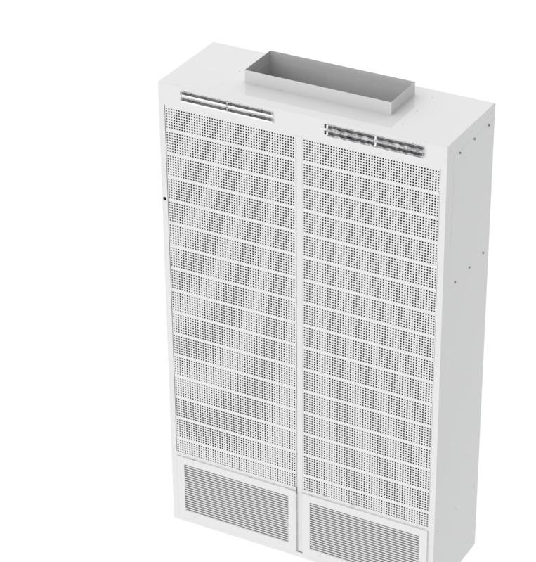
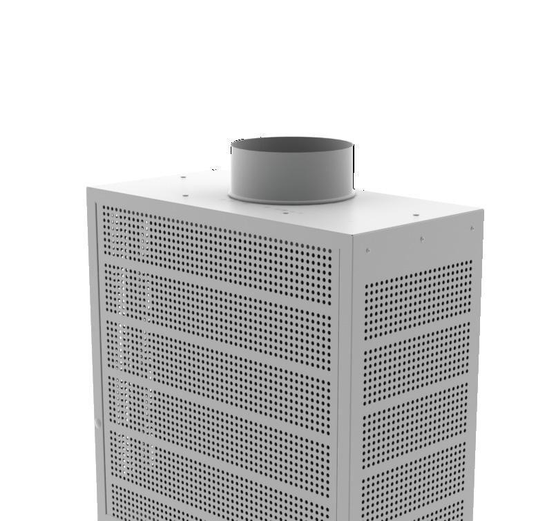
DLE-H LINEAR ENCLOSURE DISPLACEMENT DIFFUSER WITH INTEGRAL HEAT
 LINEAR ENCLOSURE DISPLACEMENT DIFFUSER WITH INTEGRAL HEAT The (DLE-H) uniquely combines natural convective heating with low level displacement cooling into one cabinet enclosure. The heating option is
YORK PASSIVE CHILLED BEAMS ENGINEERING GUIDE
 YORK PASSIVE CHILLED BEAMS ENGINEERING GUIDE Contents YORK Passive Chilled Beams 3 CB-PBE-YK / CB-PBR-YK Performance Data 5 CB-PBE-YK Dimensions 7 CB-PBR-YK Dimensions 8 Specifications 9 2 YORK Passive
PRODUCTS DISPLACEMENT VENTILATION ADVANCING THE SCIENCE OF AIR DISTRIBUTION. Redefine your comfort zone.
 A I R D I S T R I B U T I O N PRODUCTS C O R E 04 ADVANCING THE SCIENCE OF AIR DISTRIBUTION DISPLACEMENT VENTILATION Redefine your comfort zone. www.titus-hvac.com Rethink what air management systems can
APPLICATION GUIDE DISPLACEMENT
 DISPLACEMENT APPLICATION GUIDE HOW DOES DISPLACEMENT WORK? ventilation provides low velocity air at around 65 F that relies on buoyancy forces to drive the air motion. Supply air spreads across the floor
LEED v4 Building Design and Construction Quiz #8 EQ
 LEED v4 Building Design and Construction Quiz #8 EQ 1. Which of these is considered an unoccupied space? [Choose three] A. School classroom B. Mechanical room C. Meeting room D. Locker room E. Restroom
Chilled Beams Selection BY DAN INT-HOUT, FELLOW ASHRAE; AND LILLI WILBAR
 This article was published in ASHRAE Journal, November 2014. Copyright 2014 ASHRAE. Reprinted here by permission from ASHRAE at www.krueger-hvac.com This article may not be copied nor distributed in either
ENERGY EFFICIENT AIR QUALITY CONTROL IN LABORATORIES USING BENCH EXHAUSTS
 ENERGY EFFICIENT AIR QUALITY CONTROL IN LABORATORIES USING BENCH EXHAUSTS Farhad Memarzadeh 1, Jane Jiang 2, and Andy Manning 2 1 PhD, PE, National Institutes of Health, Bethesda, MD, USA 2 PhD, Flomerics,
EVALUATION OF DISPLACEMENT VENTILATION FOR HIGH-CEILING AREAS
 2 Elsevier Science Ltd. All rights reserved. Air Distribulion in Rooms, (ROOMVENT 2) Editor: H.B. Awbi 725 EVALUATION OF DISPLACEMENT VENTILATION FOR HIGH-CEILING AREAS Anthony Arens, Leon Glicksman, Qingyan
Designing Air-Distribution Systems To Maximize Comfort
 Designing Air-Distribution Systems To Maximize Comfort By David A. John, P.E., Member ASHRAE An air-distribution system that provides occupant thermal comfort can be a complicated system to predict and
TDPs provide you with new technical training materials designed to help your contractors, engineers, and designers to effectively design, specify,
 TDP Catalog TDPs provide you with new technical training materials designed to help your contractors, engineers, and designers to effectively design, specify, sell, and apply HVAC equipment in commercial
LIFE CYCLE COST OF DISPLACEMENT VENTILATION IN AN OFFICE BUILDING WITH A HOT AND HUMID CLIMATE
 LIFE CYCLE COST OF DISPLACEMENT VENTILATION IN AN OFFICE BUILDING WITH A HOT AND HUMID CLIMATE By LANE W. BURT A THESIS PRESENTED TO THE GRADUATE SCHOOL OF THE UNIVERSITY OF FLORIDA IN PARTIAL FULFILLMENT
Terminal. 3 Las Vegas, NV
 McCarran International Airport Terminal 3 Thesiss Proposal Mechanical Systems Project Proposal December 18, 2007 Prepared By: Jason A. Witterman Faculty Advisor: Dr. William Bahnfleth, Ph.D., P..E. Table
SOUND APPLICATION GUIDE
 SOUND APPLICATION GUIDE Vertical Stacked Water Source Heat Pump VPCS Models NEW RELEASE Form 1.-AG1 (8) LD9 FORM 1.-AG1 ISSUE DATE: 8// TABLE OF CONTENTS GUIDELINES AND EXAMPLES...3 Overview...3 Sound
HOW THE NUMBER AND PLACEMENT OF SENSORS CONTROLLING ROOM AIR DISTRIBUTION SYSTEMS AFFECT ENERGY USE AND COMFORT
 HOW THE NUMBER AND PLACEMENT OF SENSORS CONTROLLING ROOM AIR DISTRIBUTION SYSTEMS AFFECT ENERGY USE AND COMFORT Danni Wang Graduate Student Edward Arens Director Tom Webster Research Specialist Center
Fundamentals of Acoustics
 providing insights for today s hvac system designer Engineers Newsletter volume 47 4 Understanding VAV Sound Standards Acoustics are an important and often overlooked topic in HVAC&R. Many pieces of equipment
in UFAD Systems The control of room-air stratification is Design Guidelines for Stratification
 Design Guidelines for Stratification in UFAD Systems Guidance for sizing interior and perimeter zones of underfloor-air-distribution systems Editor s note: This is the first of two articles based largely
While underfloor air. Learning objectives
 Displacement ventilation best practices Displacement ventilation (DV) is a low-velocity, non-turbulent cooling system for commercial buildings that is not always fully understood. Learn when and where
Engineering Update JANUARY VOLUME 9 THIS PACKAGE INCLUDES A COLLECTION OF ARTICLES FROM VOLUME 9 OF THE JANUARY 2013 ENGINEERING UPDATE.
 Engineering Update JANUARY 2013 - VOLUME 9 THIS PACKAGE INCLUDES A COLLECTION OF ARTICLES FROM VOLUME 9 OF THE JANUARY 2013 ENGINEERING UPDATE. TABLE OF CONTENTS: Two Sides to Every Noise... 1 Product
CAE 331/513 Building Science Fall 2017
 CAE 331/513 Building Science Fall 2017 November 14, 2017 Heating load calculations Advancing energy, environmental, and sustainability research within the built environment www.built-envi.com Twitter:
ASHRAE Standard Ventilation Compliance Evaluation Mechanical Technical Report #1. Bronx School for Law, Government, & Justice Bronx, NY
 ASHRAE Standard 62.1 2004 Ventilation Compliance Evaluation Mechanical Technical Report #1 Bronx, NY Prepared By: Yulien Wong Faculty Advisor: Dr. Jelena Srebric October 4, 2005 TABLE OF CONTENTS 1.0 EXECUTIVE
COMPUTER MODELING OF UNDERFLOOR AIR SUPPLY SYSTEM
 COMPUTER MODELING OF UNDERFLOOR AIR SUPPLY SYSTEM JJ Kim, JD Chang, and JC Park Taubman College of Architecture and Urban Planning, University of Michigan, Ann Arbor, MI, USA ABSTRACT An underfloor air
FUNDAMENTALS OF CHILLED BEAMS ANSI/ASHRAE STANDARD , METHODS OF TESTING CHILLED BEAMS
 FUNDAMENTALS OF CHILLED BEAMS ANSI/ASHRAE STANDARD 200-2015, METHODS OF TESTING CHILLED BEAMS NEMIC 2017 Hello! I am Davor Novosel I am here because I love to share what I know about chilled beams with
Oklahoma University Children s Medical Office Building
 Oklahoma University Children s Medical Office Building Oklahoma City, O.K., BAE Advisor: Laura Miller Presentation Outline VRF System Dedicated Outdoor Air System Evaluation VRF Indoor Units Design Criteria
Spending Through the Roof: Tall Building Energy Wasted Through Passive Vents. Building Energy 2017 A presentation by: Jamie Kleinberg & Robin Neri
 Spending Through the Roof: Tall Building Energy Wasted Through Passive Vents Building Energy 2017 A presentation by: Jamie Kleinberg & Robin Neri Project Objective: Develop and test methods for estimating
PRODUCTS SOLAR PLEXICON PRODUCT: ADVANCING THE SCIENCE OF AIR DISTRIBUTION. Redefine your comfort zone.
 A I R D I S T R I B U T I O N PRODUCTS PRODUCT: SOLAR PLEXICON F O C U S 05 ADVANCING THE SCIENCE OF AIR DISTRIBUTION Redefine your comfort zone. www.titus-hvac.com Rethink what air management systems
Proposed Addendum L to Standard , Ventilation for Acceptable Indoor Air Quality
 BSR/ASHRAE Addendum L to ANSI/ASHRAE Standard 62.1-2016 Public Review Draft Proposed Addendum L to Standard 62.1-2016, Ventilation for Acceptable Indoor Air Quality Second Public Review (August 2018) (Draft
Mechanical Systems Proposal
 Mechanical Systems Proposal Prepared for: Dr. William Bahnfleth, Professor The Pennsylvania State University, Department of Architectural Engineering Prepared by: Chris Nicolais Mechanical Option December
NVR / NVS / NVF / NVA
 NVR / / NVF / NV Product Overview Models Rectangular Roof Stack Unit Square Roof Stack Unit Facade Mounted Natural Vent Wall Mounted Transfer Unit NVR NVF NV The Price natural ventilation system operates
The Pennsylvania State University. The Graduate School. Department or Architectural Engineering THERMAL AND VENTILATION PERFORMANCE
 The Pennsylvania State University The Graduate School Department or Architectural Engineering THERMAL AND VENTILATION PERFORMANCE OF COMBINED PASSIVE CHILLED BEAM DISPLACEMENT VENTILATION SYSTEMS A Thesis
Dan Int-Hout Chief Engineer, Krueger Richardson, Texas
 Effective Room Air Distribution Dan Int-Hout Chief Engineer, Krueger Richardson, Texas Where We Are Today: Agenda Overview LEED issues and Update Diffuser Selection Perimeter Acoustics Thermal Comfort
South Jefferson High School Huyett Road Charles Town, WV 25414
 Thesis Proposal Mechanical System Redesign Report Charles Town, WV 25414 Prepared for Dr. Jelena Srebric The Pennsylvania State University By Jonathon Gridley Friday, December 15, 2006 1.0 Table of Contents
Enhancing Acoustic Performance through the use of Window Shade Fabric White Paper
 Enhancing Acoustic Performance through the use of Window Shade Fabric White Paper As architecture and design evolve, more demand can be seen for obtaining creative solutions for occupancy comfort. In designing
ENGINEERING UPDATE JULY VOLUME 11 THIS PACKAGE INCLUDES A COLLECTION OF ARTICLES FROM VOLUME 11 OF THE JULY 2013 ENGINEERING UPDATE.
 ENGINEERING UPDATE JULY 2013 - VOLUME 11 THIS PACKAGE INCLUDES A COLLECTION OF ARTICLES FROM VOLUME 11 OF THE JULY 2013 ENGINEERING UPDATE. TABLE OF CONTENTS: Terminal Unit Acoustical Considerations...
Comparison of airflow and contaminant distributions in rooms with traditional displacement ventilation and under-floor air distribution systems
 Lee, K.S., Zhang, T., Jiang, Z., and Chen, Q. 2009. Comparison of airflow and contaminant distributions in rooms with traditional displacement ventilation and under-floor air distribution systems, ASRAE
Chilled Beams. The new system of choice?
 Chilled Beams The new system of choice? Presented By: Kevin M. Pope P.E. Jason Leffingwell Hammel Green And Abrahamson, Inc. and Ken Bauer, P.E., LEED AP Butters-Fetting Co., Inc. History of Chilled Beams
Design Standard Sustainability
 Design Standard Sustainability Purpose Educational institutions have the ability to influence the ideals and principles of our future decision makers; as such, East Side Union High School District (ESUHSD)
BUILDING DESIGN FOR HOT AND HUMID CLIMATES IMPLICATIONS ON THERMAL COMFORT AND ENERGY EFFICIENCY. Dr Mirek Piechowski 1, Adrian Rowe 1
 BUILDING DESIGN FOR HOT AND HUMID CLIMATES IMPLICATIONS ON THERMAL COMFORT AND ENERGY EFFICIENCY Dr Mirek Piechowski 1, Adrian Rowe 1 Meinhardt Building Science Group, Meinhardt Australia 1 Level 12, 501
From: Tyler Adams, Mei Wu Acoustics
 Experts in acoustics, noise and vibration To: Jim Inglis, Stanford University John D. Donahoe, Stanford University Doug Sams, ZGF jinglis@stanford.edu jdonahoe@stanford.edu doug.sams@zgf.com From: Tyler
McCarran International Airport Terminal 3
 McCarran International Airport Terminal 3 The Pennsylvania State University Architectural Engineering Senior Thesis Final Report Evaluation of Underfloor Air Distribution and Displacement Ventilation Systems
2015 International Mechanical Code Errata (Portions of text and tables not shown are unaffected by the errata)
") PIPING MATERIAL 1 ST PRINTING (September 1, 2015) CHAPTER 3 GENERAL REGULATIONS TABLE 305.4 PIPING SUPPORT SPACING a MAXIMUM HORIZONTAL SPACING (feet) MAXIMUM VERTICAL SPACING (feet) ABS pipe 4 10 c Aluminum
PIPING MATERIAL 1 ST PRINTING (September 1, 2015) CHAPTER 3 GENERAL REGULATIONS TABLE 305.4 PIPING SUPPORT SPACING a MAXIMUM HORIZONTAL SPACING (feet) MAXIMUM VERTICAL SPACING (feet) ABS pipe 4 10 c Aluminum
Numerical Investigation on Ventilation Strategy for Laboratories: A Novel Approach to Control Thermal Comfort Using Cooling Panels
 Numerical Investigation on Ventilation Strategy for Laboratories: A Novel Approach to Control Thermal Comfort Using Cooling Panels Farhad Memarzadeh 1, Andy Manning 2 and Zheng Jiang 2 1 National Institutes
Published in: Proceedings of the 7th International Conference on Healthy Buildings 2003, Singapore, December 2003, Vol. 2
 Aalborg Universitet Design Methods for Air Distribution Systems and Comparison Between Mixing Ventilation and Displacement Ventilation Nielsen, Peter Vilhelm; Larsen, Tine Steen; Topp, Claus Published
Ceiling Radiant Cooling Panels
 Copyright 2006, American Society of Heating, Refrigerating and Air-Conditioning Engineers, Inc This posting is by permission from ASHE Journal This article may not be copied nor distributed in either paper
A Sensitivity Analysis on Mixing Energy Loss in Air-Conditioned Rooms by Using CFD
 A Sensitivity Analysis on Mixing Energy Loss in Air-Conditioned Rooms by Using CFD S. Iizuka 1, S. Shiba 1,*, M. Sasaki 1, M. Okumiya 1 1 Nagoya University, Nagoya, Japan ABSTRACT In some office buildings,
NEW FOUR STORY MIXED USE RESTAURANT, RETAIL, LODGING, AND OFFICE BUILDING OWNER S PROJECT REQUIREMENTS
 NEW FOUR STORY MIXED USE RESTAURANT, RETAIL, LODGING, AND OFFICE BUILDING OWNER S PROJECT REQUIREMENTS TABLE OF CONTENTS Introduction Page 2 Project Description Page 2 Owner s Directives Page 4 Design
NUMERICAL MODELING OF THE INFLUENCE OF ANGLE ADJUSTMENT OF A/C DIFFUSER VANES ON THERMAL COMFORT IN A COMPUTER ROOM
 Seventh International IBPSA Conference Rio de Janeiro, Brazil August 13-15, 2001 NUMERICAL MODELING OF THE INFLUENCE OF ANGLE ADJUSTMENT OF A/C DIFFUSER VANES ON THERMAL COMFORT IN A COMPUTER ROOM Jan
Association of Australian Acoustical Consultants Guideline for Commercial Building Acoustics. May 2011
 Association of Australian Acoustical Consultants Guideline for Commercial Building Acoustics TABLE OF CONTENTS 1.0 INTRODUCTION... 3 2.0 OBJECTIVES... 3 3.0 CRITERIA... 5 2 1.0 INTRODUCTION Members of
15020 LABORATORIES. C. Section Building Automation and Control System Guidelines
 15020 LABORATORIES PART 1: GENERAL 1.01 RELATED SECTIONS A. Section 01004 Energy Guidelines B. Section 01008 Energy Modeling Guidelines C. Section 15955 Building Automation and Control System Guidelines
A. This Section includes ceiling- and wall-mounted diffusers, registers, grilles and louvers.
 SECTION 23 37 13 - PART 1 - GENERAL 1.1 RELATED DOCUMENTS A. Drawings and general provisions of the Contract, including General and Supplementary Conditions and Division 01 Specification Sections, apply
Ventilation. Demand-controlled ventilation (DCV) Demand-Controlled. With ASHRAE Standard Based
 Demand-Controlled. With ASHRAE Standard Based") CO Demand-Controlled 2 -Based Ventilation With ASHRAE Standard 62.1 Though not as straightforward as it once was, remains a practical way to reduce costs Editor s note: Following is an update of the November
CO Demand-Controlled 2 -Based Ventilation With ASHRAE Standard 62.1 Though not as straightforward as it once was, remains a practical way to reduce costs Editor s note: Following is an update of the November
Mechanical Technical Assignment One ASHRAE Standard Compliance Evaluation
 Mechanical Technical Assignment One ASHRAE Standard 62.1-2007 Compliance Evaluation The Prepared By: Maxwell S. Chien October 5 th, 2007 Prepared For: Dr. William P. Bahnfleth, Ph.D., P.E., Professor Department
Ceiling Radiant Cooling Panels
 2006, American Society of Heating, Refrigerating and Air-Conditioning Engineers, Inc (wwwashraeorg) Published in ASHE Journal Vol 48, Oct 2006 For personal use only Additional reproduction, distribution,
PRODUCT BROCHURE. Fixed Helical Swirl Diffuser HSC-FD HSC-FD : smartemp.com
 PRODUCT BROCHURE Fixed Helical Swirl Diffuser HSC-FD HSC-FD : 07 smartemp.com DESCRIPTION The SMARTEMP Fixed Helical Swirl Diffuser, type HSC-FD, produces highly inductive swirl discharge, diffusing the
The Creative and Performing Arts High School (CAPA) Pittsburgh, PA 9/30/2002 Andrew Tech Mechanical Option Prof. S. A. Mumma
 Pittsburgh, PA 9/30/2002 Andrew Tech Mechanical Option Prof. S. A. Mumma") LEED Green Building Certification The purpose of the LEED Green Building Rating is to provide a national standard that aims to improve environmental, health and economic performance of buildings using
LEED Green Building Certification The purpose of the LEED Green Building Rating is to provide a national standard that aims to improve environmental, health and economic performance of buildings using
Radiant Floor Cooling Combined with Mixing Ventilation in a Residential Room Thermal Comfort and Ventilation Effectiveness
 Downloaded from orbit.dtu.dk on: Apr 09, 2019 Radiant Floor Cooling Combined with Mixing Ventilation in a Residential Room Thermal Comfort and Ventilation Effectiveness Krajcik, Michal; Simone, Angela;
Cold Plane Innovative Method for Humidity Condition Control
 ISBN 978-93-84422-50-9 Proceedings of 2015 International Conference on Green Buildings, Civil and Architecture Engineering (ICGBCAE'15) Dubai, Dec. 25-26, 2015 pp. 93-97 Cold Plane Innovative Method for
THERMAL STRATIFICATION PERFORMANCE OF UNDERFLOOR AIR DISTRIBUTION (UFAD) SYSTEMS
 SYSTEMS") THEMAL TATIFICATION PEFOMANCE OF UNDEFLOO AI DITIBUTION (UFAD) YTEM TL Webster 1*, F Bauman 1, J eese 2 and M hi 1 1 Center for the Built Environment, University of California, Berkeley, CA, UA 2 York
THEMAL TATIFICATION PEFOMANCE OF UNDEFLOO AI DITIBUTION (UFAD) YTEM TL Webster 1*, F Bauman 1, J eese 2 and M hi 1 1 Center for the Built Environment, University of California, Berkeley, CA, UA 2 York
Thermal comfort study of a hawker center in Singapore
 September 004 Page of 6 Thermal comfort study of a hawker center in Singapore Song Jiafang, Wong Nyuk Hien, Agustinus Djoko Istiadji Department of Building, School of Design and Environment, National University
IMPACT OF THE AIRFLOW INTERACTION ON OCCUPANTS THERMAL COMFORT IN ROOMS WITH ACTIVE CHILLED BEAMS
 IMPACT OF THE AIRFLO INTERACTION ON OCCUPANTS THERMAL COMFORT IN ROOMS ITH ACTIVE CHILLED BEAMS Arsen Melikov 1, Boryana Yordanova 1, Lyuben Bozkhov 1, Viktor Zboril 1,2, and Risto Kosonen 3 1 International
Technical Development Program
 TDP Catalog TDPs provide you with new technical training materials designed to help your contractors, engineers, and designers to effectively design, specify, sell, and apply HVAC equipment in commercial
Ed Ferrier Applications Engineer LG Electronics USA, Inc. Commercial Air Conditioning Alpharetta, Georgia
 Ed Ferrier Applications Engineer LG Electronics USA, Inc. Commercial Air Conditioning Alpharetta, Georgia Email: ed.ferrier@lge.com 1 VRF-PI-HA-003-US 012L07 AHRI Standard 1230 2 VRF-PI-HA-003-US 012L07
LOW CARBON HEATING FOR COMMERCIAL BUILDINGS USING GRID SUPPLIED ELECTRCITY DURING-OFF PEAK PERIODS
 LOW CARBON HEATING FOR COMMERCIAL BUILDINGS USING GRID SUPPLIED ELECTRCITY DURING-OFF PEAK PERIODS R. Hutcheson, P.Eng. LEED AP, CxA, S. Jorens B.Eng., D. Knapp, PhD., P.Phys., LEED AP Arborus Consulting
LEED And Your Indoor Environment
 LEED And Your Indoor Environment An overview of LEED v3 and Indoor Air Quality David McCauley, CIE Council Certified Indoor Environmentalist ACAC CIE #1008005 USGBC's Mission To transform the way buildings
Retail Effects of ANSI/ASHRAE/IES Standard
 Retail Effects of ANSI/ASHRAE/IES Standard 90.1-2016 Prepared by Dialectic Inc. INTRODUCTION Background ANSI/ASHRAE/IES 90.1-2016 Energy Standard for Buildings Except Low-Rise Residential Buildings replaces
Aluminium Single Deflection Grilles. Model Series 5100
 Aluminium Single Deflection Grilles Model Series 5100 Aluminium Single Deflection Grilles Models 51SV and 51SH Single Deflection Supply Grilles are recommended for applications requiring pattern adjustment
Examples of IEQ factors. Healthy IEQ and energy efficiency. What type of system is the best? Ideas and concepts from research and reality.
 Healthy IEQ and energy efficiency Ideas and concepts from research and reality Lars Ekberg Energy Management AB A Chalmers Industriteknik Company 1 Examples of IEQ factors Thermal climate -operative temp.
NUMERICAL STUDY ON AIRFLOW IN AN OFFICE ROOM WITH A DISPLACEMENT VENTILATION SYSTEM Yukihiro Hashimoto 1 1
 Ninth International IBPSA Conference Montréal, Canada August 5-8, 5 NUMERICAL STUDY ON AIRFLOW IN AN OFFICE ROOM WITH A DISPLACEMENT VENTILATION SYSTEM Yukihiro Hashimoto Polytechnic University, Dept.
Modular Active Chilled Beams
 Modular Active Chilled Beams Presented by: Darren Alexander, P.Eng. Modular Active Chilled Beams Current System Solutions Fan Coil Units - Medium/High energy, medium noise solution. Output = 100-200 w/m
Noise-Foil Acoustic Metal Panels Sound Absorption Systems for Industry & Commerce
 Noise-Foil Acoustic Metal Panels Sound Absorption Systems for Industry & Commerce Abuse resistant metal jacketed constructions Lab certified acoustic performances Suitable for interior and exterior installations
LESSONS LEARNED IN MODELING UNDERFLOOR AIR DISTRIBUTION SYSTEM
 LESSONS LEARNED IN MODELING UNDERFLOOR AIR DISTRIBUTION SYSTEM Kwang Ho Lee 1, 2, Stefano Schiavon 1, Tom Webster 1, Fred Bauman 1, Jingjuan Feng 1, Tyler Hoyt 1 1 Center for the Built Environment, University
MEP's Letter of Assurance
 MEP's Letter of Assurance Instructions Multifamily Residential WELL Certification is determined by onsite Performance Verification and documentation, including Letters of Assurance from the appropriate
Demonstration of Load Shifting and Peak Load Reduction with Control of Building Thermal Mass
 Demonstration of Load Shifting and Peak Load Reduction with Control of Building Thermal Mass J. E. Braun and T. M. Lawrence, Ray W. Herrick Laboratories, Purdue University C. J. Klaassen and John M. House,
Air-Water Systems. Chilled Ceilings and Beams TROX USA. Principle of Operation. Radiant Effect on Occupants. Early 1980 s. Chilled Ceiling Panels
 Air-Water Systems and Beams Early 1980 s 1980 1990 2005 Buildings well insulated for heating Advent of personal computers Need to remove heat from space Limited space available TROX USA 1 2 Principle of
UC Berkeley HVAC Systems
 UC Berkeley HVAC Systems Title Outlook for underfloor air distribution Permalink https://escholarship.org/uc/item/5v60x57q Authors Bauman, Fred Webster, T. Publication Date 2001-06-01 Peer reviewed escholarship.org
County of Yolo Development Services Building Inspection Division
 County of Yolo Development Services Building Inspection Division 292 W. Beamer Street Woodland, CA. 95695 www.yolocounty.org (530) 666-8775 Mechanical Plan Review Comments Plan Review No. Owners Name Job
Higher Education Energy Efficiency Partnership Program BEST PRACTICES AWARDS
 Higher Education Energy Efficiency Partnership Program BEST PRACTICES AWARDS UC / CSU Sustainability Conference, June 2005 A program created by the UC/CSU/IOU Partnership and under the auspices of the
heating and the amount of * Depending on the design class and performance requirements:
 back and edge Losses Application Estimated load, Btu/ft 2 Interior floor warming 5 15 There is a difference between Interior floor heating 15 45 the amount of heat that a Exterior floor heating 60 80 room
LABORATORIES 1.01 RELATED CORNELL DESIGN AND CONSTRUCTION STANDARDS. A. Section Accessibility for People with Disabilities
 230540 LABORATORIES PART 1 GENERAL 1.01 RELATED CORNELL DESIGN AND CONSTRUCTION STANDARDS A. Section 013010 Accessibility for People with Disabilities B. Section 018120 Energy Guidelines C. Section 018130
Numerical Modeling of Buoyancy-driven Natural Ventilation in a Simple Three Storey Atrium Building
 Numerical Modeling of Buoyancy-driven Natural Ventilation in a Simple Three Storey Atrium Building Shafqat Hussain and Patrick H. Oosthuizen Department of Mechanical and Materials Engineering, Queen s
FRIDLEY SCHOOL DISTRICT West Moore Lake Drive Fridley, MN REVIEW AND COMMENT DOCUMENT
 FRIDLEY SCHOOL DISTRICT 14 6000 West Moore Lake Drive Fridley, MN 55432 REVIEW AND COMMENT DOCUMENT For submission to Minnesota Department of Education June 20, 2012 SUMMARY The Fridley Public Schools
Level 1 Modules tdp-101 hvac industry overview tdp-103 concepts of air conditioning tdp-102 abcs of comfort
 TDP-101 HVAC Industry Overview This TDP provides a general overview of the commercial HVAC industry and provides an awareness of the design process and construction. The documents involved in construction,
ORIGINAL YEAR OF CONSTRUCTION NUMBER OF BUILDING STORIES 02/06/2013 BUILDING SURVEY DATE
 0067 1110 WEST GREEN STREET URBANA, ILLINOIS 61801 SYSTEM CONDITION INDEX.810 PRIMARY BUILDING USE BUILDING SURVEY TEAM BUILDING SYSTEM REPLACEMENT COST $ 18,640,900 OFFICE BUILDING GROSS SQUARE FEET 175,513
Implementing Demand Controlled Ventilation to Meet ASHRAE Standard By KlasC. Haglid, P.E., R.A., CEM
 Implementing Demand Controlled Ventilation to Meet ASHRAE Standard 62.1-2010 By KlasC. Haglid, P.E., R.A., CEM 1 Klas C. Haglid, P.E., R.A., CEM - Bio ASHRAE Distinguished Service Award 2011 ASHRAE Handbook,
Standards for Ventilation and Indoor Air Quality in relation to the EPBD
 Standards for Ventilation and Indoor Air Quality in relation to the EPBD Bjarne W. Olesen International Center for Indoor Environment and Energy Technical University of Denmark, Denmark bwo@byg.dtu.dk
1.02 Related Sections A. Section Heating, Ventilation and Air Conditioning (HVAC). C. Section Pneumatic and Electric Control HVAC.
. C. Section Pneumatic and Electric Control HVAC.") PART 1: GENERAL 1.01 Section Includes A. Dual duct terminal units. B. Variable volume regulators. C. Integral damper motor operators. D. Integral controls. 1.02 Related Sections A. Section 23 00 00 Heating,
PART 1: GENERAL 1.01 Section Includes A. Dual duct terminal units. B. Variable volume regulators. C. Integral damper motor operators. D. Integral controls. 1.02 Related Sections A. Section 23 00 00 Heating,
1. ARI 410 Standard for chilled water, hot water and steam coils. 2. ARI 430 Central Station Air Handling Units
 PART 1: GENERAL 1.01 Purpose: A. This standard is intended to provide useful information to the Professional Service Provider (PSP) to establish a basis of design. The responsibility of the engineer is
Milwaukee, WI. Darron Rempel
 Application of Hydronic Radiant and Beam Systems ASHRAE Region IV Conference Milwaukee, WI May 14, 2010 Darron Rempel darronr@price hvac hvac.comcom Introduction Topics covered: o Theory of using water
Mechanical Systems Project Proposal
 Mechanical Systems Project Proposal December 15, 2006 Table of Contents 1.0 Executive Summary... 2 2.0 Building Background... 3 3.0 Proposal Objectives... 5 4.0 Initial Considerations... 6 5.0 Proposed