TECHNICAL MANUAL OF SOLAR THERMAL POWER PLANTS
|
|
|
- Arleen Chapman
- 5 years ago
- Views:
Transcription


1 TECHNICAL MANUAL OF SOLAR THERMAL POWER PLANTS FRANK RODRÍGUEZ TROUWBORST 1
2 INDEX I.- PURPOSE OF THE MANUAL 5 II.- GENERAL DESCRIPTION OF A PLANT 6 II.1.- Classification of collectors according to concentration ratio 6 II.2.- Parabolic Trough Collectors 10 II Parabolic Trough Collector Components 12 II Foundations and Supporting Structure 13 II Parabolic Trough Reflector 21 II Absorber or Receiver Tube 26 II Solar Tracking System 30 II Transfer Fluid 36 II Losses in a PTC 45 II Early Solar Thermal Plants 51 II Solar Thermal Parabolic Trough Collector and HTF Projects in Spain 59 II New Systems for Solar Thermal Plants using Parabolic Trough Collectors 63 II.3.- Storage for Solar Thermal PTC Plants 75 II Thermal energy storage 75 II Thermal Sensible Heat Storage 76 II Phase Change Thermal Storage 78 II Storage System Problem in Parabolic Trough Collectors Plants 80 II Thermal Storage with Oil 81 II Thermal Storage using concrete 82 II Thermal Storage using Molten Salts 83 II Prior Calculations for 10 hours of Thermal Storage 91 II.4.- Thermal Solar R&D 93 II.5.- Initial considerations for Solar Thermal Plant Commissioning and Construction 97 III.- STUDY ON THE DESIGN CONDITIONS FOR A 20 MWe SOLAR THERMAL 2
3 POWER PLANT 99 III.1.- Design Point for a Solar Field 99 III.2.- The Solar Thermal Plant Power Block under Nominal 101 III Characteristics of the Power Cycle 102 III Bypass Valves 103 III Condenser 103 III The Turbine 106 III Turbine Extractions 110 III Preheaters 110 III The Deaerator 111 III Steam Generator Feed Pumps 112 III Condensate Pumps 113 III Steam Generator 114 III Auxiliary Boiler 116 III.3.- BOP Characterisation (Auxiliary Systems) 121 III Water Treatment Plant 121 III Main Cooling System 126 III Equipment Cooling System 131 III Waste Water Treatment 131 III.4.- Study of Solar Field Design Conditions for a Solar Thermal Power Plant 137 III Various Solar Field Configurations 137 IV.- SOLAR THERMAL PLANT MAINTENANCE 144 IV.1.- Different Maintenance Strategies for a Solar Thermal Power Plant 144 IV.2.- Stages of a Maintenance Contract 145 IV.3.- Legal Maintenance 146 IV.4.- Solar Thermal Plant Maintenance 147 V.- OPERATIONAL SOLAR THERMAL PLANTS IN SPAIN 148 V.1.- Andasol V Site 148 V Project Milestones
4 V Plant Operations 149 V Electricity Production 151 V Current Regulations 151 V Solar Field. 151 V Parabolic Mirrors 155 V Absorber Tube 156 V Heat Transfer Fluid System 157 V Storage System 158 V Power Block 158 V Auxiliary Systems 162 V Control System 165 V Operations and Maintenance 165 V.2.- Alvarado V Solar Field 167 V Heat Fluid System 169 V Control over the Solar Field 171 V Power Block 171 V Auxiliary Facilities 173 V Control System 174 VI.- BIBLIOGRAPHY
5 I.- PURPOSE OF THE MANUAL The purpose of this manual is to serve as an introduction to thermoelectric solar or solar thermal technology for future prescribers, operators and maintainers of such plants. We will become acquainted with the equipment and components of a solar plant. These will include both the parts of a solar field, like collectors, loops, pipes, mirrors, receivers, etc., and the components of a power block, such as exchangers, generators, turbines, condensers and so on. We will place special emphasis on learning about the conditions required by a thermal solar plant to be manageable, as this is one of the main advantages of this technology. We will also briefly develop the basic engineering for a typical 20 MW plant, while studying the relationship between the solar field and the power block. Finally, we will study the intrinsic features of two of the first solar thermal plants to be developed in Spain. 5
6 II.- GENERAL DESCRIPTION OF A PLANT A solar thermal plant is composed of two quite distinct fields. First is the power block, which is quite similar to the power blocks installed in any electrical power plant. This power block is comprised of a series of units such as the turbine, alternator, condenser, exchangers, pumps, etc., which are units that have been extensively tested in the industrial market and are produced by a large number of manufacturers. Then, there is the solar field. Here we encounter the novelties found in this type of industrial plant, as this is main unit responsible for supplying heat to the plant. It consists of a set of mirrors that concentrate radiation in a receiving tube where it will be absorbed by a fluid. Subsequently, by means of an exchanger, it will vaporise water to be introduced into the turbine to produce electricity. The manual will lay special emphasis on this field. II.1.- Classification of collectors according to concentration ratio A solar collector is a special type of heat exchanger that transforms radiant energy from the sun into thermal energy. Collectors are different from conventional heat exchangers in a number of ways. In the latter, there is usually a fluid-to-fluid heat exchange, with high heat transfer values and no significant radiation. Solar collectors present special problems related to low and variable energy flows, where radiation is significant. Most studies on the thermal exploitation of solar radiation make their analyses on the basis of a traditional classification that distinguishes between collectors for low, medium and high temperatures. Mainly because the boundary between medium and high applications is not very clear, a more objective classification is used, depending on whether solar radiation is concentrated or not. This is why a new parameter is used: the C concentration ratio, the meaning of which is explained below. Low temperature solar applications always use solar collectors with no concentration: that is, C=1. In this case, all the components of the solar subsystem have the same physical location. In higher temperature applications, there are two clearly distinct parts of the collector with different functions and locations: the receptor and the concentrator. The receptor is the element in the system where radiation is absorbed and is converted into a different type of energy. 6
7 The concentrator or optic system is the part of the collector that directs the radiation towards the receiver. The aperture of the concentrator is the open space through which solar radiation enters the collector. The surface concentration ratio is the ratio between concentrator aperture area and the receptor area. This concentration ratio distinguishes the following solar thermal technologies Non-glass collectors 1. 2 Flat plate collectors 1. Without concentration C= Selective surface absorber 1. 3 Advanced collectors Collectors evacuated Types of collectors depending Vac uum tubes of the concentration ratio 2. 1 Parabolic trough syste ms C= With concentration C> Power tower systems C= Parabolic dishes or Stirling dish C= Non-concentrating collectors are designed for applications that demand a relatively low temperature, generally up to 100ºC, although with vacuum tubes they can reach up to 130ºC. They exploit both direct and diffuse radiation, do not require monitoring of the solar trajectory and need only minimal maintenance. They are also much simpler mechanically than concentrating collectors. According to the diagram above, this type of solar collectors is subdivided in turn into three groups, from lesser to greater technical complexity: - Non-glass collectors. - Flat plate collectors. 7


8 - Advanced collectors With regard to concentrating collectors, we have the following types, from lesser to greater concentration ratio: - Parabolic trough systems. - Power tower systems. - Parabolic dishes or Stirling disks We shall briefly define each type of concentrating collector. Parabolic trough systems consist of cylindrical mirrors whose transversal section is a parabola, thus concentrating solar radiation on the focal point. These collectors achieve concentration ratios between 30 and 90. This type of technology includes Fresnel collectors. Parabolic Trough Collectors Fresnel Collectors Power tower systems are composed of quasi-flat mirrors called heliostats distributed on a horizontal surface and tilted to reflect sunlight on the top of the tower, where the receiver is generally placed. The concentration factors range between 200 and 1,

9 Power Tower Parabolic dishes or Stirling dishes are parabolic rotating mirrors that move in such a way that they are always oriented towards the sun. This third type achieves the highest concentration ratios: between 1,000 and 5,
. Hence, the optimal geometry of the concentrator is that of a paraboloid of rotation that moves in such a way that it is always oriented towards the sun.")
10 Stirling Dish Each of these three technologies seeks to concentrate solar rays which are approximately parallel and incident on a large surface area (the concentrator), into a relatively small surface area (the receiver). Hence, the optimal geometry of the concentrator is that of a paraboloid of rotation that moves in such a way that it is always oriented towards the sun. This is precisely the geometry adopted by parabolic dishes, have the highest concentration levels. Other technologies also seek to attain these conditions. In parabolic trough systems, the transversal section is a parabola, thus allowing for sunlight to be concentrated throughout an axis. Of the three concentration collector technologies, this SOLAR THERMAL PLANT MANUAL will focus on parabolic trough collectors, as this is the technology now seeing very high rates of growth in Spain. II.2.- Parabolic Trough Collectors As noted, parabolic trough collectors (PTC) are concentrated solar collectors that transform direct sunlight into thermal energy by heating a working flow to temperatures that, until quite recently, could reach 400ºC. Thus, these are classified as medium 10
11 temperature solar collectors. This limitation was imposed not only by the working fluid (synthetic oil) but also by the maximum temperature allowable by the selective surface. With respect to the former limitation, working fluids that can sustain higher temperatures are now being used, such as molten salt and water vapour. For the latter limitation, new absorber tubes with selective surfaces that can sustain higher temperatures without deteriorating have been created. These tubes should be on the market in a relatively short time. At first, as these collectors could reach temperatures above 260 ºC, they were used and are still used - to provide a power supply for a wide variety of industrial processes that require heat processing. Although this application gave rise to the development of parabolic trough collectors in the 1970s and 1980s, there were three obstacles that prevented the technology from taking over the market. The first obstacle lay in the engineering and business effort that was required, even in small projects. The second lay in the decisions made by customers, many of which prevented a project from being completed successfully, when a major effort had already been undertaken to apply this technology. The last factor was performance, which did not always meet industrial standards for a profitable project. Even so, PTCs are still used to power a wide variety of industrial processes: Acetone production, the dairy industry and waste processing, among others, thus replacing traditional fossil fuels in these applications. Subsequently, research in cylindrical parabolic collectors began to focus on the production of electricity; soon giving rise to what is still a reliable test of the technological maturity of PTCs: Solar Electric Generating System (SEGS) power plants, with an approximate surface area of 2.5 million square meters in California, and a total net power of 340 MW. These plants appeared in parallel fashion with other demonstration projects for electricity production from solar energy, mainly in Europe: Eurelios in Italy, Themis in France, SSPS and CESA 1 in Spain, in Japan, the Soviet Union and the United States, in addition to SEGS plants and the Solar One solar thermal project. All of these plants were spurred by a surge in the oil prices in the 1970s. However, the fall in the price of oil in the 1980s brought to the fore the need to reduce costs and increase the efficiency of PTC solar systems to boost their competitiveness against conventional systems based on fossil fuels. The technology used in SEGS plants is called Heat Transfer Fluid (HTF), and it consists of using a means of heat transfer (usually synthetic oil) that transports the thermal energy supplied by a PTC solar field to the power block, where, by means of a heat exchanger, the energy is used to feed a Rankine water vapour cycle. For some time, studies had explored the possibility of generating vapour directly in collector tubes by means of a number of demonstration projects that had not resulted in the commercial exploitation of the technology owing to a number of technical issues that were essential for the process to be viable. These issues include the temperature gradients and 11
12 the stress produced in the absorbing tubes as a result of the two-phase water and vapour flow in its interior. Experimental research is also necessary into the different forms in which vapour can be produced directly in PTCs, as well as its control and storage. In order to resolve these and other issues, in 1996 the Direct Solar Steam (DISS) project was begun in the Solar Platform of Almeria (PSA in Spanish) with a limited number of collectors. The DVG process took place at this platform under real solar conditions, with two-phase water vapour flows under high pressure. Diss. Solar Plataform of Almería II Parabolic Trough Collector Components A parabolic trough solar collector consists of a cylindrical parabolic concentrator that reflects direct sunlight on the focal point of the parabola, located on the receiver: the absorption tube. From a structural point of view, these collectors consist of four main parts. 12

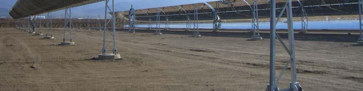
13 II Foundations and Supporting Structure The foundation sustains the collectors that are fastened to the ground to enable the frame to support the loads for which it was designed. The collector loads depend on the structural dimensions and characteristics and are reflected in the weight and wind load. Another important factor is the type of terrain. The material used is standard reinforced concrete. Depending on the characteristics of the site, one or another solution will be used; but one form of resolving the problem is to introduce six cylindrical reinforced concrete piles with a volume of 2.27 m 3 through a loop as the central support and 48 cylindrical 1.14 m 3 reinforced concrete piles as intermediate supports. In other projects, this problem has been solved with the use of reinforced piles that are 40 x 40 cm in width, 4 m in length, topped by a pile cap that will not protrude by more than 15 cm above ground level. In this case, the PTC structure shall comprise 12 pillars of metallic structure. Ten typical pylon to support the parabolas, one drive pylon and a shared pylon for a PTC that is joined with the adjacent one or an end pylon for the collector at the end of the loop. The pylons shall be placed as follows. The drive pylon is placed in the centre of the collector and will include the collector's drive and the local control panel to control the movements of the parabolas comprising the PTC. 13
14 Each drive pylon has a drive system, which is the hydraulic system that moves the parabolas. The most important components in plants are the radiation sensors, the position sensors, the hydraulic oil temperature sensors, automatisms (PLC and positioner card), hoses and hydraulic connections, electric pump and drive pistons. We will discuss these components further on. Collectors can be mounted horizontally or to make use of the natural inclination of the terrain. If given an east-west orientation, it will be horizontal - this configuration is not being used in plants in Spain - whereas, if given a north-south orientation, either of these options may be used, provided that the inclination is towards the south and the slope is small. The purpose of the collector frame is to lend rigidity to the set of elements comprising it, and to act as an interface with the foundations of the collector itself. To date, structures used in parabolic trough structures are all metallic, although research has begun into other materials, like glass fibre, plastic and even wood for the parabola itself. The supports or pillars are also metallic, but they may also be mounted with concrete, thus joining with the foundations as a single unit. Two main techniques are used to build the parabola structure: spatial and central support or torque tube. The former is used in LS-3 collectors by Luz and the second, which was used in LS-1 and LS-2 collectors, also by Luz. The LS-2 collector system is based on an axial tube that supports metallic profiles to which the mirrors are fastened and lends the entire structure the integrity and structural rigidity necessary. The structure of the LS-3 collector is not only larger than the LS-2 collector, but also represents a change of philosophy. While the mechanical components of the LS-2 model were designed with high degrees of tolerance and assembled at the installation site to attain the optic performance required, the LS-3 consists of a central frame comprising a guide pattern that is fine tuned before final installation. The result of this innovation is a lighter and more durable structure that is capable of operating with great precision under conditions of strong winds. The figures below depict the transversal sections of the LS-2 and LS-3 collectors. 14

15 LS-2 structure LS-3 structure The LS-3 collector has been used in the most recent SEGS plants (SEGS-VII to SEGS-IX). Furthermore, for Direct Steam Generation tests conducted in Almeria, a variation on the LS-3 collector was used which allowed a few degrees of inclination. Although the operational experience with the LS-3 collector has been excellent, showing a large capacity for tracking, the thermal performance of the collector and its maintenance were not the equal of its predecessor, the LS-2. Luz changed designs in order to lower the cost of the collector in large fields. It is not yet known if the design of the LS-3 will represent a capital benefit over the design of the LS-2, as the initial advantages of the former may be neutralised by issues of performance and maintenance. Based on the experience and the lessons learned with SEGS plants, there are now new collector designs in development, as described below. 15
 does")
16 The design of the Eurotrough collector belongs to a consortium of European companies and research laboratories: Inabensa, Fichtner Solar, Flabeg Solar, SBP, Iberdrola, Ciemat, DLR, Solel and CRES. The Eurotrough collector and its variations employ the philosophy of a central tube, but rather than mounting a helicoidal tube, a longitudinal square structure (support frame or torque box) does most of the work. Eurotrough Parabolic Trough Collector This design eliminates many of the problems associated with LS-2 and LS-3 collectors found in manufacture and operation. It basically consists of a rectangular frame with supporting arms for the mirrors that reduces the load on the glass panels by a factor of three and, thus, reduces breakage of glass under strong wind conditions. The rotation axis is in the centre of gravity, a few millimetres above the external frame. As the structure is subject to lower wind loads and dead weights, there are fewer deformations in operation, thus boosting optical performance. Its rigid design also allowed for the collector to be lengthened, thus yielding two different versions of the Eurotrough collector with 100 and 150 metres in total length for each collector, respectively, with only two differences between them: the number of parabolic trough modules included in each collector (eight in 16
17 the ET-100 and twelve in the ET-150) and the power of the hydraulic drive. It also allows for the possibility of mounting on inclined terrains (3% slope). As noted, although the total length is either 100 or 150 metres, the distinctive element of the Eurotrough collector is a steel support structure measuring metres in length called the module, with a straight rectangular section that sustains the support arms of the facets of a parabolic mirror with an aperture of 5.76 metres. Based on the experience acquired in two generations of Eurotrough solar collectors, a German development group comprised of Flagsol, Solar Millennium and the engineering firm SBP (Schlaich Bergermann und Partner) concentrated on systematically exploiting the design experiences of the ET collectors to enable their commercial use in the next generation of solar thermal plants with parabolic trough collectors. As a result of this work, a third generation emerged of the Eurotrough collector, the SKAL-ET, with an industrial design that reduced the cost of a collector to approximately 200 /m2. The reduction was achieved by means of the following measures: - Reducing the specific weight of the collector to approximately 28 kg/m2. - Reducing the number of components to improve large-scale production. - Allowing for on-site construction and reducing building costs. - Reducing operating and maintenance requirements. - Enhancing the rigidity of the collector, thus increasing the optical performance by up to 80%, whereby enabling operation in more unfavourable wind conditions and increasing annual output. Trials on a complete loop (4,360 m2) of SKAL-ET collectors have been ongoing in the SEGS-V plant for more than 3 years to improve the design. At present, three large-scale projects are using this type of collector: Andasol-1 and Puertollano (now complete) and Andasol-2 in Spain. In addition, this collector will be used in the Integrated Solar Combined Cycle Systems (ISCCS) plant to be installed in Kuraymat, Egypt. This represents 1.2 Million m2 of SKAL-ET collectors under construction, which is more than any other type of collector. 17

18 LS2 PTC Vs Eurotrough PTC The company Solargenix Energy (formerly Duke Solar) has developed a new parabolic trough collector, the Solargenix design, based on an aluminium space frame. Although the concept is patterned after the LS-2 collector, the new design is superior to the LS-2 in terms of structural properties, weight, manufacturing simplicity, corrosion resistance, manufactured cost and installation ease. The National Renewable Energy Institute (NREL) has been charged with evaluating the optical performance of several generations of Solargenix collectors and other optical issues to verify the accuracy of the parabolic shape and the alignment of the mirrors. The latest generation of these collectors, the Solargenix SGX-1, has been implemented in the Nevada Solar One solar thermal plant of 64 MW. In addition to these commercial collectors, noteworthy is the prototype developed by SENER; which is based on the concept of a central support tube or torque tube, like the LS- 1 and LS-2 collectors. 18


19 Senertrough Senertrough 19
20 Also notable are the collectors that the companies Abengoa and Acciona are implementing in their projects. Solar Field for the company Acciona The latest example of collectors based on metallic frames is a prototype that has been undergoing tests since September The collector is called HelioTrough and it was developed by the Solar Millennium Group, specifically a subsidiary called Flagsol. To test the response of the prototype, an 800 m-long loop has been set up, consisting of two rows of collectors in one of the solar thermal plants already operating in the southwest of the United States. These new collectors are 192 metres long and have an aperture of 6.7 metres (the SKAL-ET collectors measure 148 metres and have a width of 5.7 metres). The collectors have an uninterrupted mirror surface and a significantly larger aperture. This type of collectors reduces its predecessor s concentration ratio of 82 to 76. The diameter of the receiving tube has also been changed and increased from 70 mm to 89 mm, which allows for an increase in the flow of HTF, thus reducing the parasitic losses in pumping. For the commercial exploitation of these collectors, molten salts are to be used as a heat transfer fluid to attain working temperatures of 500ºC, which implies increased efficiency in the cycle. Another of the advantages of this collector is that it reduces the demand for labour, 20
 and greater cost savings of guide systems, hydraulic pumps and flow")
21 as its standard components allow for shorter building times. In short, new HelioTrough collectors achieve 10% greater efficiency than other collectors. This is because of their greater size (approximately 1,400 m 2 of aperture per collector, compared with 900 m 2 of the SKAL-ET) and greater cost savings of guide systems, hydraulic pumps and flow measuring equipment. II Parabolic Trough Reflector The purpose of a parabolic trough reflector is, as its name indicates, to reflect the sunlight it receives and to project it in a concentrated manner on the absorber tube on the focal point of the reflector. To perform these reflections, silver or aluminium films placed on supports lending sufficient rigidity are used. These support media may be metallic, plastic or glass sheeting. In the case of metallic sheet, the same material usually has a dual role of support and reflector. Thus, polished aluminium sheets with an approximate reflectance of 80% are commonly used. The main advantage of this system is its low cost. However, because the reflectance of aluminium quickly deteriorates when the material is exposed to the elements, aluminium sheet reflectors are not often used in applications that require high levels of durability Set of Collectors in a Solar Field 21
22 When the supporting medium of the reflecting film is plastic, a silver or aluminium film is placed on it, thus yielding a thin reflective plastic film that can be glued to any rigid support. The company 3M has a number of products of this kind, such as the ECP-305. As in the foregoing case, the main problem with these reflective films is their low durability to the elements, as the particles carried by the air scratch and erode the surface, causing a loss of specularity. Most often, glass is used as the supporting medium. In this case, a fine silver film protected by copper film and one of epoxy paint is placed on the reverse side of the glass. Depending on the thickness of the glass on which the reflective silver film is placed, there are two types of mirrors: a) thick glass (thickness > 3 mm), or b) thin glass (thickness < 1.5 mm). When thick glass is used as the support, prior to placement of the silver film, the glass is hot curved in special ovens to the parabolic shape, allowing the mirrors to be positioned directly on the collector s metallic frame. This type of mirrors are used in LS-3 and Eurotrough collectors. When the glass is not very thick (<1.5 mm), the mirrors have sufficient flexibility to be cold curved and they can be fastened directly onto the frame made of metal, glass fibre or other type of material, which ensures the correct curvature of the concentrator. If the frame is rigid enough, it will ensure the parabolic trough shape; if the frame is thin for example, a metal sheet of mm in thickness, the shape will be created by the frame itself. The reason silver and not aluminium is used is that silver has a significantly higher degree of reflectivity than aluminium, even though the manufacturing cost is similar. Recently installed glass mirrors with silver film can achieve a solar reflectivity of approximately 93.5%. In addition, the working experience with these mirrors in SEGS plants has been very good: reflectivity suffered practically no degradation and mirror failures were minimal, although some failures have been recorded on the sides of the Barlovento field, where there is no wind protection. As the mirror failures can damage the receptor tube and cause breakage in other mirrors, experiments are being conducted with a thicker and more resistant mirror to be placed in perimeter locations at the SEGS-VIII and SEGS-IX plants, where there is a greater wind load. 22


23 Thin Glass Thick Glass Set of Collectors in a Solar Field 23
24 The maker of Flabeg Solar mirrors is responsible for manufacturing mirrors for all the solar thermal plants being installed in Spain. The RP3 model mirrors are being installed in all of these plants, except in La Risca and Palma del Rio, where RP2 models have been installed. These mirrors are of the following sizes: RP3 Inner Mirror 1,700 mm x 1,641 mm = 2.79 m 2 Outer Mirror 1,700 mm x 1,568 mm = 2.67 m 2 RP2 Inner Mirror 1,570 mm x 1,400 mm = 2.2 m 2 Outer Mirror 1,570 mm x 1,324 mm = 2.08 m 2 Finally, the most innovative of the manufacturers of reflective mirrors is the German company Solarlite. These mirrors use ultrathin glass that is 0.95 mm thick to achieve reflectively above 94%. The glass is embedded in a self-carrying structure consisting of a resin composite that gives it a sandwich design. As they are fastened to the frame, the mirrors are not affected by gusts of wind and, hence, will attain better performance and the likelihood of detachment is practically non-existent. Set of parabolic trough collectors made by the company Solarlite. Their metallic frame is far inferior to other collectors owing to the lower weight of the collectors. The role of the frame is to reinforce the collector against moments of torsion. 24

25 Set of collectors by Solarlite Special vehicles have been developed to clean the mirrors, with the following characteristics: The chassis weighs 15 tn and the truck is 9.2 m long. The arm used to clean the mirrors and the receiver tube is automated. It is equipped with seven adjustable nozzles to clean the mirrors, plus one to clean the receiver tube. The vehicles carry two boilers of 240,000 kcal to heat the cleaning fluid to a temperature range between 30ºC and 75ºC. They carry a high-pressure pump. They have a 13 kw service generator. Two pressure pipes with 40-metre rollers. Each pipe supplies water under the following conditions (200 bar, 42 l/min). The vehicle has an auxiliary fire protection exit. The characteristics of the water it supplies are as follows: 7 bar, 172 l/min. They are equipped with a tank filling system. The fill intake measures 4. The water accumulation tank has a capacity of 5,000 l. The interior of the vehicle is equipped with a touch screen for operations and night-vision cameras with a 7 monitor to operate the cleaning arm and to 25
26 enable the vehicle to go into reverse. Lighting consists of three 150 w spotlights. Washing speed is between 7 and 10 km/h. In addition, other vehicles have been designed to drain the thermal oil circuits in solar thermal plants. Heat insulated and pressured INOX steel vat. 4,000 l capacity. Compressor with refrigeration dryer to drive HTF through loop. Extraction pump of up to 400ºC. Discharge pump of 16 bar and 100ºC. In order to empty a loop, dry air or N2 is introduced through the venting valve and through the intake valve. The oil is extracted and transferred to an expansion tank. II Absorber or Receiver Tube The linear receiver on the parabolic trough collector, also called a heat collector element (HCE), converts concentrated sunlight into thermal energy that transports the heat fluid. It is also on the focal line of the parabolic trough concentrator, fastened to the frame with support arms. This is one of the essential components of any PTC, as the overall performance of the collector largely depends on it. It consists of an absorber tube that is, in turn, comprised of two concentric tubes: an interior metallic tube through which the heat transfer fluid flows, and the other, exterior glass tube. The metallic tube carries a selective coating that lends it a high rate of absorptivity (~94%) in the range of sunlight and low emissivity in the infrared spectrum (~15%), which provides a high rate of thermal performance. For temperatures of up to 425ºC, selective coating consists of cermet (material composed of metallic and ceramic compounds) composites yielded by sputtering or the PVD (physical vapour deposition) process, which attain absorptivity levels above 95% and emissivity of 15% even at temperatures below 400ºC. The main problem with PVD coatings is that most of them degrade upon contact with the air when they are hot, thus requiring a high degree of vacuum in the chamber between the interior metallic tube and the glass envelope. The glass tube around the interior metallic tube has a twofold purpose: firstly, to protect the selective coating from meteorological conditions and secondly, to reduce thermal loss from convection in the absorber tube. The tube usually has antireflective treatment on both sides in order to increase transmissivity and, hence, the optical performance of the collector. 26
27 When a vacuum is created between the metallic tube and the glass tube to prevent the degradation of the selective surface, the ends of the tubes are joined using a glassmetal weld to a ball joint that is welded at the other end to the interior metallic tube. This achieves a water-tight annular space between the metallic inner tube and the exterior glass tube, while the ball joint compensates for the differing thermal dilation of the glass and metal tubes at working temperatures. To ensure the vacuum in the annular space, small parts called getters are usually attached to the metallic tube in order to absorb the scarce molecules from different substances that might penetrate this space over time. These molecules may come from the exterior owing to a failure in the glass-metal weld or a small crack or they may even come from within the metallic tube: for when oil surpasses 400ºC, it may decompose and release gases that can leak into the annular space. When absorbing impurities in the space, the getter changes colour, thus enabling plant personnel to detect any breakage in the receiver tube. To create the vacuum, once the tube has been manufactured, a vacuum pump is connected to a small intake in the glass envelope (evacuation nozzle), which is sealed when the desired vacuum is reached. Receiver Tube 27


28 The figure shows the absorber tube on the LS-3 collector, which was designed by the company Luz in the 1980s. The receiver is comprised of a stainless steel tube of 70 mm in exterior diameter, with a cermet absorbent surface, wrapped in an antireflective glass tube of 115 mm in exterior diameter, where a vacuum has been made in the annular space. Although their level of performance was quite high, the first Luz absorber tubes also had a high failure rate of approximately 4-5% a year. These failures included vacuum loss, breakage of the glass envelope and the degradation of the selective coating, which inevitably occurred in the presence of oxygen once the vacuum had been lost. Any one of these failures resulted in a major loss in thermal performance. In SEGS plants, the replacement of broken tubes, mostly due to inappropriate activities performed during installation or in subsequent operation, entailed high operating and maintenance costs. Even though this type of failures has been significantly reduced, it remains substantial. Breakage of the tube usually occurs in the glass-metal weld owing to the incidence of sunlight concentrated on the weld. At present, a number of projects are seeking to modify the configuration of this weld by protecting this part of the collector from sunlight in order to maintain the levels of thermal and mechanical stress below the glass breakage threshold. Joining of two Collectors (Andasol-1) 28
29 As noted, the company Luz manufactured the receivers for all SEGS plants. When this company went out of business, Solel Solar Systems acquired the Luz line of receiver production and continues to manufacture spare parts for SEGS facilities. Solel has continued to develop the absorber tube and sought to enhance its performance. This has led to an improved design called Universal Vacuum Heat Collector Element (UVAC-HCE). This tube includes an inner reflective coating that protects the interior of the glass-metal weld from low solar angles in working conditions. The UVAC also uses different compositions of selective cermet coating, thus eliminating the risk of oxidation from vacuum loss. The German tube maker Schott has solved this problem by giving the glass and metal the same dilation coefficient to minimise problems from thermal stress. With a view to enhancing the performance of parabolic trough collectors, the German company Schott has designed a new selective coating called New Absorber Coating or NAC that can work at temperatures of up to 550ºC with high solar absorptivity and low thermal emissivity. The absorber is comprised of a thin reflective cover, a high-quality cermet coating to absorb sunlight and, finally a thin coating with a very low refraction rate to enhance solar absorptivity. To replace absorber tubes that are no longer in existing plants, options with a lower cost and performance than those presented are preferred, thus giving rise to a series of modified designs with a lower cost. For example, Sunray Energy, the SEGS II plant operator, has developed a new receiver design with the support of Sandia National Laboratories (SNL). The receiver is made with recycled stainless steel tubes that can be repaired on site. A thin layer of black, 2500 series Pyromark paint is used as an absorber coating. The replacement of old tubes with this new design accounts for 90% of the performance of UVAC tubes and 30% of the cost. Another option presently under development for a low-cost absorber tube is based on the use of a new selective coating known as black crystal. It is being developed by Energy Laboratories, Inc. (ELI) and Sandia National Laboratories (SNL). This coating includes a layer of solgel that reduces oxidation in the presence of air in the annular space. Its solar absorptivity is 0.94 and thermal emissivity is 0.25 at 300ºC; it also presents thermal stability on stainless steel substrates up to temperatures of 375ºC and it can also be applied either to new stainless steel tubes or tubes in operation with damaged coating. These new tubes must be tested in the field in order to evaluate their long-term operation and durability. 29


30 II Solar Tracking System In order to concentrate sunlight on the absorber tube, the PTC must be focused towards the sun during the day. Thus, it needs a solar tracking mechanism to change the position of the collector with the apparent movements of the sun in the sky. The most common tracking system is a device that turns the collector s parabolic trough reflectors around on an axis. Although parabolic trough collectors that can turn on two axes have also been made, experience has shown that such collectors do not perform as well as those which track on a single elevation axis. In spite of the fact that the amount of energy captured by a collector with a two-axis tracking system is greater and has greater peak performance, thermal loss is also greater because the length of the passive tubes in the collector is also greater. Moreover, collectors with single-axis tracking have lower costs and are more cost-effective as they are simpler mechanically; they are also more robust, whereby resisting greater wind loads. This gives them long survival periods, fewer breakdowns or deformations and longer possible operating hours. Pilot Plant. Two-axis (PSA) 30

31 Normalmente, los CCPs se instalan de forma que su eje de giro quede orientado en la dirección Este-Oeste o Norte-Sur, aunque se pueden utilizar también orientaciones intermedias. La figura muestra las dos orientaciones más usuales. North South Orientation East West Orientation Eurotrough Collector Movement The rotation of the collector requires a drive mechanism that can be either electric or hydraulic to move the collector in line with the position of the sun. The figure shows the two most common types of drive mechanisms. 31


32 Electric motor with gear reducer Hydraulic mechanism In the most common case of autonomous or distributed collectors, the electrical mechanisms consist of a motor coupled to a gear reducer with an output axis that is rigidly joined to the collector s rotation axis, like the mechanism shown in the figure. This type of mechanism is suitable for small and medium-sized collectors that do not require high torques in the collector axis. In such mechanisms, like the LS-3 or Eurotrough models, the high torque levels required to rotate the collector demand the use of hydraulic mechanisms like the one shown in the figure. In these mechanisms, an electrical pump feeds the two hydraulic pistons, which rotate the collector frame throughout the tracking axis. To keep costs down and simplify the construction of the PTC collector, a single drive mechanism must be capable of moving several serially connected concentrator modules operated jointly as a single element. Thus, in LS-3 collectors, 8 modules are driven and in Eurotroughs, up to 12 units are driven simultaneously. 32

33 Details on Hydraulic Arms As noted above, the movement of the collector is controlled electronically to keep it perfectly focused towards the sun. Depending on their degree of complexity, a certain number of tasks can be automated. There are two concepts for this task: direct tracking with solar sensors (photocells) in an open loop or tracking with calculation of the sun s position with the use of angular encoders in the collector axis in a closed or mixed loop as a reference point. There are two basic approaches to solar sensors: shadow band sensors and flow line sensors. Shadow band sensors are made of two photocells mounted on a flat surface. The cells are separated by a thin wall (shadow band) and the sensor unit is mounted on the PTC so that the sun is at a normal angle from the surface when the collector is well focused and the shadow band is parallel to the collector s turn axis. Hence, when the collector is oriented in such a way that sunlight is perpendicular to the plane of the photocells, the shadow band will not throw a shadow on any of the photocells and the output signal will be balanced. As the sun moves across the sky, the shadow band begins to partially shadow one of the photocells and to cause an imbalance in the electrical signals sent by both photocells. This 33
34 imbalance between the outputs from the photocells is processed by an electronic comparator that, depending on the magnitude and the polarity of the difference between the signals, orders the drive mechanism to rotate the collector in the right direction until the shadow disappears and the signals from the photocells coincide. Flow line sensors are mounted on the absorber tube itself. They consist of two photocells on either side of the tube that detect the flow concentrated in the absorber. The collector is properly oriented when both sensors are identically lit and send the same signal. The two types of solar sensors described provide good tracking precision of up to 0.05º. The other way of making the PTC follow the sun is with mathematical algorithms that yield highly accurate calculations of the sun s coordinates in relation to the collector. Maintaining an angular encoder coupled to the collector s rotation axis provides precise and instantaneous data on the position of the collector, where the relation is 12,546 bits for 360º (an example). If the position of the collector indicated by the angular encoder is not correct for the collector to be properly focused according to the sun s position as calculated by the algorithm, an electronic controller orders the mechanism to move the collector until the position of its turn axis is correct. Each PTC has a local controller and a hydraulic drive unit. The local controller receives the position indicator signal and uses the temperature sensors to ensure that the thermal oil does not exceed the maximum temperature. The solar field is controlled from two points. From a field supervisor controller (FSC). This system is centralised in a field control room. From a local controller within each collector (LOC). The FSC monitors the insolation and wind conditions, as well as the circulation of thermal fluid through the status of the pumps, in communication with all the LOCs. If the proper working conditions are obtained, the FSC starts up plant operation by ordering the collectors to follow the solar position and to stop at night or in situations that endanger the integrity of the plant, such as strong winds above 20 m/s. Once the field is operating in a stable manner, the FSC renders control over each individual collector to its LOC. The solar field operates under the control of the field supervisor controller (FSC), which is a computer in the central control room that communicates with each of the local controllers and the plant s distributed control centre (LOC). The FSC starts up the solar field operations at dawn or when plant availability allows it, and stops operations at night or in the event of strong gusts of wind. 34

35 A meteorological station is installed near the area where the power system is located. The information it generates affects the operation of the solar field. Radiation data is used to determine the performance of the solar field and the wind speed data is necessary to stop the field in the event of high speeds. In short, the FSC communicates with the plant's distributed control system, which coordinates and integrates the power system, the thermal transfer system and the solar field. Each PTC functions as an independent unit, concentrating solar energy with a solar tracking system, and its own communications and control system. Hence, each unit is equipped with local measuring equipment and its own local controller (LOC) keeping the reflector panel facing the sun and protecting the absorber tubes from overheating. Each and every one of the local controllers will be linked to the field supervisor controller in the central control room. The FSC sends the local controllers the pertinent operating orders and receives information of their status and any alarms on any of them. In turn, the FSC will be part of a distributed control system comprising other control units responsible for other central equipment units, such as the turbo-generator, the vapour generators, the electricity system, water treatment, etc. The process when using solar calculations is as follows: - Calculation of the position of the sun. 35
36 - Measurement of the position of each collector. - Correction of position. - Management of communications with collectors. - Operating modes for each collector and set points - Detection of errors or disturbances and reporting to central control - Emergency actions and alarm triggers. Therefore, the most common set up involves six pumps feeding 12 hydraulic arms on the same loop. The electricity consumption of each pump is 0.55 kw and the working pressure is 120 bar. In addition to these elements, each loop will contain the following instrumentation: - 42 high-precision temperature sensors, PT100s for absolute measurement with 3 mm in diameter thermocouple temperature sensors to measure the input and output difference on collectors with a 2 mm exterior diameter. - 6 dataloggers (data retrieval hardware). - 6 EMCO (FLM1 and FLM3) flow meters to install in the input piping on the collectors. - 6 Endres + Hauser fluid velocity meters to be installed in collector loops. Once the collector has been analysed from a structural point of view, another important aspect is described below: the different heat transfer flows that can be used in this type of collector. II Transfer Fluid Parabolic trough collectors use a heat transfer fluid that absorbs sunlight in the form of thermal energy by circulating through the receiver tube and transfers it to the power block. The type of heat transfer fluid used will determine the working temperature range of the solar field and, consequently, the performance that can be yielded from the power cycle. One of the advantages of parabolic trough technology is its capacity to store thermal energy for use during non-insolation periods. Thermal storage implies over-dimensioning the solar field and an increase in the annual capacity factor of the plant. In good insolation conditions, a parabolic trough collector field has an annual capacity factor of 25%. With thermal storage, this capacity factor can be as high as 50% or more. 36
37 Although components are being developed to work at higher temperatures, the ideal working temperature range for parabolic trough collectors is 150ºC-400ºC. In higher temperatures, these collectors suffer from high thermal losses that reduce their performance. For temperatures below 150ºC, more cost-efficient collectors are available, such as vacuum tube collectors. If the temperatures to be reached are moderate (<175ºC), use of demineralised water as a working fluid is relatively problem-free, as the working pressure is not excessive. In contrast, synthetic oil is used in applications where higher temperatures are sought (125ºC < T < 400ºC). The reason lies in the fact that, under high temperatures, the pipes would be subject to high pressure if the working fluid is water, because keeping water from evaporating requires maintaining it at a pressure higher than the saturation pressure at the maximum temperature reached by water in solar collectors. With oil, the pressures required are much lower, as the vapour pressure at a given temperature is much lower than that of water. Working at lower temperatures allows us to use more cost-efficient materials for tubes and simplifies both installation and safety measures. The oil most commonly used in present-day parabolic trough collector solar plants is Therminol VP-1. This synthetic oil works well at 400ºC, although its handicap is that it has a freezing point of 12ºC, which means that the entire oil circuit must be kept above this temperature at all times. This is usually not a problem, as very little auxiliary power from the boilers is needed to maintain the oil above its freezing point. Although this will be discussed at length in the following sections, these auxiliary boilers are natural gas heaters with 50% of capacity, power of 350,000 kw, an oil input temperature of 288ºC and an output temperature of 391ºC. These boilers are supplemented by air preheaters, along with induced and forced ventilators. Auxiliary Boilers 37
38 Therminol VP-1 oil, which is a eutectic mixture meaning that its freezing point is lower than that of each of its separate components made up of biphenyl and diphenyl ether. In use over time, this oil will undergo degradation, which will significantly affect two important aspects such as cost-efficiency and safety, as these are hazardous substances. There are a number of reasons for this degradation, but three stand out in particular. - Owing to contamination or to residues of existing substances inside the receiver tube, or from contamination owing to a mix with water in the vapour generator. The first type of contamination can be prevented by flushing. Flushing involves circulating a fluid through the receiver tubes at a speed that is far greater than the usual working speed (3.5 m/sec), thus modifying the circulation system from laminar to turbulent. To carry out this process, the drivers must be disconnected valves, filters, pumps, etc. and a special pump connected that is capable of pumping twice the usual flow, thus attaining a turbulent system. To trap the dirt being released from the tubes, filters must be placed successively in a manner that reduces the passage width and the first filters will catch the largest particles and the rest will steadily diminish. Different fluids can be used in the flushing process, but using the actual heat carrying fluid is the most common approach. The second type of contamination, namely water, will occur in the vapour generator, specifically in the reheater, as it will be the exchanger with the largest temperature differences between the heat carrying fluid and the fluid in the water vapour circuit. The most failure-prone point is the weld between the tube plate and each of the tubes. - Leaks can cause oxidation of the oil in contact with ambient oxygen. - Cracking process whereby complex molecules are broken down into simpler ones owing to a momentary temperature spike above 400ºC. This can occur on the walls of the absorber tube and in the auxiliary boiler. Any of these three conditions can lead to either long-chain or short-chain hydrocarbons that can substantially alter the viscosity of the fluids, like easily burning acids that cause corrosion. The number of feed pumps in a solar field can vary, but three pumps are most commonly used to circulate the oil throughout the solar field. These are multi-stage horizontal 515 rpm x cm 3 pumps, with a total length of 220 metres, 2,600 kw of electrical power and a variable speed motor. Approximately 2.32 dm 3 /m 2 of collector oil is needed to operate the solar field. 38
39 Solar Field Feed Pumps Before the oil enters the pumps and after having released the heat it carried in the heat exchange processes, the oil is homogenised either through collectors that will lend the solar field s feed pumps the manometric delivery head; in which case, and to support cases of the solar field discharge, there will be four expansion tanks with horizontal trough HTF with a 4,300 mm in diameter, 18,000 mm in length, 13 mm in thickness, 30,800 kg in weight and they will be made of semi-hard steel. 39
40 Oil Homogenisation Collectors Expansion Tanks 40
41 The other alternative involves the four expansion tanks being used to homogenise the oil from the exchangers. In this case, one will be at placed in the upper part of the plant. Overflow tanks are also commonly used. These are a series of pressurised tanks at ground level that collect both the thermal fluid that overflows the expansion tanks and the clean thermal fluid from the thermal oil regeneration system. These two systems are known, respectively, as ullage systems and recovery systems. These overflow tanks are pressurised at 11.5 bar in normal operations by means of injecting nitrogen at the same pressure. Apart from containing the overflows from the expansion tank and the clean thermal fluid from the plant regeneration system, the overflow tanks are part of the main collector system, together with the auxiliary storage tank. This main collector system is a series of tanks that, in total, must have the capacity to store and contain all the thermal fluid in the facility. 1. Ullage System The Ullage system comprises a total of three pressurised tanks that fulfil two main functions: During the heating of the facility and the venting of nitrogen into the atmosphere, low-boiling vapour is released and the nitrogen and the lowboiling vapour from the ullage system are condensed in the reduction system. These condensed products are collected in the ullage system s drain tank. The ullage system separates the low-boiling vapour from the thermal fluid and collects it in order to check the purity of the thermal oil. Of the three tanks in the ullage system, two are located one after another and the third is the drain collection and final product collection tank. The first two tanks are set at high levels, while the drain tank is placed at zero elevation in the facility. The first of the two tanks in the ullage system is equipped with an external cooling system for the thermal fluid condensed in it. When the thermal fluid condenses in the first tank, it is pumped through an air cooler and then back into the tank to keep it at a temperature of about 175 ºC. The thermal fluid stored in the first tank is now clean. When the thermal fluid level in the first tank reaches a pre-determined level, another pump drives the now clean thermal fluid back into the thermal fluid circuit through one of the overflow tanks described above. Before reaching the second tank in the ullage system, the low-boiling vapour and nitrogen coming out of the first tanks goes through an air cooler where they condense at a 41
42 temperature of roughly 60ºC. In the second tank, the condensates are cooled to 38ºC with a cold water coil. When the condensation level reaches 3 m 3, the condensates go to the ullage system s drain tanks for collection and treatment. 2. Recovery System The recovery system, along with the ullage system, is part of the facility s thermal fluid regeneration system. The recovery system is made up of two pressurised tanks with the primary function of removing the low-boiling vapours caused by oil degradation from the thermal fluid before they exceed their maximum solubility and begin to enter the system. The recovery tanks are set at ground level. Along with these tanks, an auxiliary storage tank is also used during the facility filling process. As the thermal fluid is delivered to the site, it is kept temporarily in the storage tank until it is injected into the system. The storage tank is made of steel and pressurised with nitrogen in order to prevent contact with the air and oil degradation. This auxiliary tank is equipped with two immersed electrical resistors placed at different heights above the bottom of the tank to provide the power needed to keep the thermal fluid within at 50ºC and prevent the freezing of HTF on cold days. Finally, the fluid transfer system is equipped with an air cooler and an air condenser. These two units are either installed or they form part of the thermal fluid regeneration system. The air cooler uses air to cool the clean thermal fluid being stored in the first of the tanks in the ullage system from 180ºC to 170ºC. The fluid cooling pump of the ullage system vacuums the hot oil from the tanks and does so through a battery of air cooler tubes, where a current of air generated by the unit ventilators enables the necessary heat exchange. The air cooler s function is to condense the mix of vapours that are below boiling point and the nitrogen before they reach the second tank in the ullage system. Thus, the vapours go through the battery of tubes of the air condenser, where a flow of air generated by the fans enables the necessary heat exchange. To protect against fires, a nitrogen gas tank that is also horizontal cylindrical will also be included: it is 3,650 mm in diameter, 18,300 in length, 200 mm thick, weighs 38,500 kg and is made of semi-hard steel. 42
 above which they degrade.")
43 If one wishes to dispense with the problem of cooling, oils are available that can work at temperatures of roughly 400ºC and do not have such a high freezing point. For example, the freezing point of Syltherm-800 is -40ºC. In any event, synthetic oils always have the disadvantage of a temperature limit (400ºC) above which they degrade. Until relatively recently, this was not a disadvantage, as the tubes selective surface could not withstand such high temperatures. As we have seen, advanced components are being developed for tubes that can endure higher temperatures. In this case, the working fluid cannot be oil, but rather molten salts or water-vapour. Both the ENEA (Ente per le Nuove Tecnologie, l Energia e l Ambiente) and the SNL are conducting research on molten salts. The following salts are used in these applications: Solar Salt, Hitec and Hitec XL. The main problem with all of these is their high melting point: between 142ºC, for Hitec salt and 220ºC for Solar Salt, which demands electrical resistance in the interior of the absorber tubes, with the technical complexity this entails. As noted at the beginning, whether molten salts or oil are used, the technology used in a solar thermal plant to produce electricity is called Heat Transfer Fluid (HTF). As an alternative, the direct use of water in the absorber tubes has always been a quite attractive option, in spite of the high pressures that is required at high temperatures. This technology is called direct vapour generation (DVG). In short, we will now illustrate some of these components with a series of photographs taken at the Andasol-1 plant. Collector Stock (Andasol-1) 43
")

44 Assembly of the Structures (Andasol-1) Assembly of the Mirrors (Andasol-1) 44

45 Assembly of the Receiver (Andasol-1) II Losses in a PTC When solar radiation reaches the surface of a parabolic collector, a large amount of radiation is lost, owing to a number of factors. The total losses can be divided into three groups: - Geometric losses - Thermal losses from the receiver tube into the atmosphere - Optical losses 1. Geometric Losses Geometric losses cause a reduction in collectors effective capture area. PTC plants have two types of geometric losses: - Owing to the collectors relative position to each other. This first type is called shadow loss and it is caused by the partial shadow some collectors can cast onto adjacent collectors. Obviously, the greater the distance between the parallel collector rows, the less shadow they can cast on one another. Under the sunlight conditions of Spain, we can tentatively use three times the width 45
46 of the parabola as the distance between collector rows, as shown below. - Inherent to each collector. The geometric losses inherent to each PTC are caused by the fact that the collectors are equipped with a single-axis solar tracking system and, hence, can only rotate on this axis. This gives rise to the so-called incidence angle φ, which is the angle formed by direct sunlight on the aperture plane of the collector and the perpendicular to this aperture plane. This incidence angle depends on the time of day and the day of the year, as it depends on the coordinates of the sun against a Cartesian system originating in the collector, and it causes a loss of useful reflective space at the ends of the collector. The Figure shows a longitudinal cross-section of a PTC. The radiation reflected by the section of reflective surface with length L E cannot be intercepted by the absorber tube. The area of the collector lost owing to this phenomenon S E, is yielded in the following equations: 46
47 Where A is the width of the parabolic trough concentrator, L the length of the parabolic trough concentrator, F the focal distance from the parabola, Fm the average distance between the surface of the parabola and the absorber in the same transversal section of the collector and φ the incidence angle of direct solar radiation. The existence of an incidence angle not only reduces the effective capture area of the collector, but also affects reflectivity, absorptivity and transmissivity, as these parameters present a maximum value when the incidence angle is 0º. 2. Optical losses Optical losses occur when neither the reflective surface of the concentrator is a perfect reflector nor the glass covering the metallic absorbent tube is fully transparent and the selective surface of the metallic tube is not a perfect absorbent and the geometry of the parabolic concentrator is not perfect. These imperfections mean that only a part of the direct sunlight on the surface of the parabolic concentrator reaches the fluid circulating within the absorbent tube. The figure shows the four parameters involved in the optical losses of a PTC, which are: - Reflectivity of the surface of the concentrator ρ. The reflective surfaces of collectors are not perfect, so only a part of the incident radiation is reflected. Typical reflectivity levels are roughly 90%. However, reflectivity levels diminish progressively as dirt builds up on the surface. For example, the 47
48 reflectivity of the parabolic collectors in the Solar Platform of Almeria is 92% when the collectors are clean. These levels fall by 0.26% a day owing to the steady build up of dirt on the mirrors. Hence the importance of cleaning the collectors during maintenance. - Interception factor γ. A fraction of the solar radiation reflected off the mirrors does not reach the glass envelope of the absorber tube for a number of reasons: microscopic or macroscopic imperfections on the mirrors, collector positioning errors, or even blocking by the supports of the absorber tube. Imperfections in mirrors and possible errors in solar tracking prevent some rays from intercepting the absorber tube on the path after reflection. These losses are quantified by the so called interception factor. A typical value for this optical parameter is 95%. - Transmissivity of glass envelope, ζ. The metallic absorber tube is in the glass envelope to reduce thermal loss and protect the selective surface. A fraction of the solar radiation reflected off the mirrors that reaches the glass envelope of the absorber tube cannot pass through it. The ratio between the radiation that passes through the glass envelope and the total incident radiation yields the transmissivity of the glass envelope. The typical value of this parameter is 90-95%, depending on whether the glass has been subject to anti-reflective treatment or not. - Absorptivity of selective surface α. This parameter quantifies the amount of incident radiation on the selective surface that the surface can absorb. A typical level of absorptivity is between 90-96%. The product of the four parameters described above reflectivity, absorptivity, transmissivity and interception factor - is called the PTC s peak optical performance. 3. Thermal Losses Thermal losses are the second most important type of losses in a PTC, after optical losses. These occur mainly in two places: in the absorber tube and in the thermal fluid tubes, although the losses in the former are much larger. The thermal losses associated with the absorber tube comprise: heat losses from conduction through the supports of absorber tubes, losses from radiation, convection and conduction from the absorber metallic tube to the glass envelope and losses from convection and radiation from the glass tube into the atmosphere. In absorber tubes where there is a gap between the metallic tube and the glass tube, thermal losses from conduction and convection from the metallic tube to the glass envelope are eliminated and there are only radiation losses between the metallic tube and the glass envelope. 48
49 Each of the aforementioned thermal losses could be calculated analytically with the well-known equations that govern heat transfer processes by radiation, convection and conduction. However, in practice, overall thermal losses, QL, are calculated in a PTC with a global coefficient for thermal losses from the absorber tube into the atmosphere, U L : Where T abs is the average temperature of the metallic absorber tube, T amb is the ambient temperature, D 0 is the exterior diameter of the metallic absorber tube and L is the length of the tube (which is the same as the length of the PTC). In this equation, the global loss coefficient is given by the unit of the absorber tube area and its units are (W/m2 abs ºC). The global coefficient of thermal loss is a figure provided by the collector manufacturer and is determined in practice by subjecting the collector to a number of thermal loss tests in the temperature range for which the collector was designed. An approximate value of the global loss coefficient, UL abs, for a PTC with a vacuum absorber tube is approximately 4 W/m2 abs ºC for temperatures of roughly 350 ºC. As a result of all these losses optical, geometric and thermal - the useful thermal energy generated by a PTC is lower than it would be in ideal conditions, where such losses did not occur. PTC: There are usually three different performance types and a parameter defined in a - Optical performance with an incidence angle of 0º (peak optical performance), η opt,0º. This includes all the optical losses that occur in the collector with an incidence angle of 0º. Its value is given by the product of these four factors: the reflectivity of mirrors, the transmissivity of the glass tube, the interception factor (which includes the portion of radiation reflected that does not reach the absorber for some reason) and the absorptivity of the selective surface coating the absorber metallic tube. - Thermal performance, η th. It includes all the thermal losses occurring in the collector. - Global performance, η global. Includes all losses, whether optical, geometric or thermal, which occur in the collector. - Incidence angle modifier, K. Includes all the optical or geometric losses that occur in the collector for an incidence angle φ 0º and does not take into 49
50 account η opt,0º (geometric losses at the end of the collector, blocking of concentrated radiation by the supports of the absorber tube and influence of incidence angle on absorptivity and transmissivity of absorber tube and reflectivity of mirrors). The incident solar energy on a parabolic trough collector is yielded by: Where: Q sol = incident solar energy on the collector (W) S c = aperture area on the reflective surface of the collector (m2) I = direct sunlight (W/m2) φ = incidence angle On the other hand, useful thermal energy supplied by the collector is given in terms of the enthalpic gain of the collector working fluid, as: Where: Q útil = useful thermal energy supplied by the collector (W) q m = operating fluid mass flow (kg/s) h sal = enthalpic heat transfer fluid at the collector input (J/kg h ent = enthalpic heat transfer fluid at the collector output (J/kg) The global performance of the trough collector is given as the quotient between the useful thermal energy supplied by the collector and its incident solar energy: The following figure graphically represents the energy balance in a PTC, illustrating the significance of yields and the angle of incidence modifier explained previously. 50

51 Optimum performance η opt,0º does not depend on solar radiation, or on the temperature of the enthalpic heat transfer fluid, but on the fouling factor of the collectors. This factor affects mirror reflectivity and the transmissivity of the glass envelope for the absorber tube. This dependence means that when this value is given, the manufacturer must specify the degree of cleaning for which it is valid. The degree of cleaning refers to mirror reflectivity and the transmissivity of the glass tube. A typical optimum performance value is approximately 0.75, for a 100% degree of cleanliness. The angle of incidence modifier, K, is directly dependent on the angle of incidence, where K=1 for φ = 0º, and K=0 for φ = 90º. The value K is given as a function of K=K(φ), which is determined experimentally. The thermal yield directly depends on the temperature of the heat transfer fluid and on the direct sunlight. II Early Solar Thermal Plants Like other solar concentration technologies, the great development of parabolic trough collectors emerged in the mid-1970s, due to a sudden rise in the cost of petroleum. This development shaped into three different projects: - A 150 kw irrigation system, connected to a field of parabolic trough collectors, in Coolidge, AZ, USA (1979). - The experimental IEA-SSPS 500 kw plant (International Energy Agency Small Solar Power System) installed at PSA (1981), which was framed within a collaborative R & D project run by the International Energy Agency. 51
52 - SEGS plants (Solar Electricity Generating Systems), with a total nominal power of 340 MW, which was commercially developed by a group of American, Israeli and German companies and operated by Luz International Ltd., Los Angeles, CA, USA. Due to the importance of SEGS plants, this section is dedicated to them -- the last of the projects listed in the previous paragraph. Luz International Limited, founded in 1979, designed, marketed and installed the nine large solar energy production plants, named Solar Electric Generating System (SEGS), one of the greatest exponents for the viability of parabolic trough collector technology for electricity production. Of the nine SEGS plants installed by Luz in California (USA), eight are currently in daily operation, with a nominal power of 340MW. A fire in February 1999 in the first (SEGS- I) plant put it out of operation. The SEGS plants have been designed and operate as peak-load centres, in order to supply maximum power at peak demand times. This means that their capacity factor is low (30%), and the number of hours equivalent to full-load operation is 2,500 to 3,000 h/year. Another significant limitation in the SEGS plant design is that due to federal regulations (US Federal Energy Regulatory Commission), the consumption of fossil fuels by these plants (natural gas) is limited to 25% of the thermal energy contributed annually, if they wished to make use of the favourable tariff law. This, together with the high cost of thermal storage, is the cause of the low capacity factors for these plants. The California SEGS plants have a fairly conventional power block. In the first plants, the thermodynamic cycle used was a Rankine cycle without reheating, while the SEGS-VI plant used a Rankine cycle with reheating. All these cycles are highly regenerative, in contrast to the conventional thermal plant cycles which do not financially compensate the need for so many turbine extractions to reach these power levels. This difference is a common aspect to all solar thermal plants, and is due to the high cost of investment associated with the solar equipment for a solar thermal plant. Any improvement in the performance of the thermodynamic cycle employed means the ability to save on solar equipment. All the California SEGS plants use oil (at a pressure of approximately 35 bar) for their heat transfer fluid and oil-water exchangers, which limits the maximum temperature the cycle can reach. It is for this reason that despite using highly regenerative cycles, thermal yield is low (30%) compared with conventional fossil fuel plants. To overcome this limitation, SEGS-I to VII feature a hybrid system that allows for fossil fuel heat supply to increase the quality of the live steam and with it the thermal yield 52
53 of the cycle. However, this requires the use of a boiler, which means low operational flexibility which makes adequate connection with the solar field difficult. There are three basic systems of hybridisation implemented in SEGS: - Natural gas superheater. This is the system implemented in the SEGS-I, with fossil fuels contributing 18% of the total thermal yield of the plant. A significant inconvenience of this hybridization method is the limited flexibility of the plant, as it cannot operate without solar energy. To partially overcome this limitation, this plant is equipped with thermal storage equivalent to three hours of full load operation (140 MWth of capacity). - Fossil fuel boiler in conjunction with the solar system. SEGS-II to VII use this system. In these types a fossil fuel boiler is connected to the solar system and is capable of supporting and substituting it. With this configuration the plant can function in solar mode only, or fossil fuel mode, or in hybrid, which greatly increases its flexibility in terms of the requirements of the electricity network to which it is connected, given that it need not limit its operation to daylight hours. An added advantage of this hybridisation model was its ability to do without the storage system which would have been costly as the output of these types of plants was greater than that of SEGS-I. - Fossil fuel heater for the oil circuit. SEGS VIII-IX use this system. It consists of placing a fossil fuel heater along the oil circuit, in parallel with the solar field, to provide auxiliary energy in the case that the solar energy is insufficient to heat the oil to the required temperature. There are two main disadvantages to this hybridisation method. On the one hand, connecting the fossil fuel heater to the primary circuit makes it subject to the limited maximum temperature permitted for the oil, which limits the quality that can be obtained later in the live steam. On the other hand, the fossil energy is reduced due to losses in the oil-water heat exchangers, while in the previous systems the fossil energy was directly introduced into the water-steam circuit. The advantage of this system, which in an analysis of the viability of SEG-VIII to IX should compensate for the aforementioned disadvantages, is the greater agility of the oil heater with respect to the steam generator, as it reduces the heat lost during the boiler heating periods. 1. SEGS-I The oldest of the SEGS plants has a nominal power output of 13.8 MW, operating with a Rankine cycle with regeneration. Its construction began in October 1984 and it started operating on 20 December The solar field had a collector surface of 82,969 m2, comprised of 560 first generation modular collectors, (model LS-1), installed in 140 parallel rows. 53
54 Operational Diagram In accordance with the operational diagram, ESSO 500 oil is pumped from a cold oil tank to the solar field, where it is discharged at a temperature of 307ºC, then stored in the hot oil tank, and later passes through a steam generator to produce saturated steam at 36.3 bar. The saturated steam is reheated up to 415 ºC in a natural gas heater, and later expands when passing through the turbine. Following discharge from the steam turbine, it is condensed in the refrigeration system, then again passes through the steam generator in order to start the cycle again. With a relatively low live steam temperature and the cycle lacking the power from reheating, the live steam pressure must be low (35.3 bar) to avoid excessive humidity in the last stages of the turbine. With these live steam characteristics, the net thermal yield of the cycle is 29.6%. 2. SEGS-II Construction of the SEGS-II plant commenced in February 1985, with operations starting in December of that same year. The nominal power of the plant is 30 MW. The collector field covers a surface area of 165,376 m2. Type LS-1 collectors are used, as in the previous plant type. However, this plant exchanged the mineral oil used in the SEGS-I plant for synthetic oil, which allows for the solar field temperature to increase from 307 ºC to 316 ºC. This more expensive synthetic oil, together with the power output of the plant (double 54
55 that of SEGS-I), meant that the investment was cost prohibitive. The figure demonstrates the SEGS-II operating system. As can be seen from the figure, the idea of the gas superheater was maintained to improve the live steam characteristics. Furthermore, the absence of storage gave rise to the use of a hybridisation system with a natural gas boiler in parallel with the solar field, which offers the possibility of operating with fossil fuel only, increasing its reliability. The thermodynamic cycle used is the regenerative Rankine cycle without reheating. In solar-only operation, without the gas superheater, the characteristics of the live steam are even worse than those of the SEGS-I; therefore, with a live steam temperature in the order of 295 ºC ºC, the pressure is limited to some 27.2 bar, and the net thermal yield to 26.7%. However, in hybrid functioning or fossil fuel only, the live steam is generated at 510 ºC and 105 bar, so that a net thermal yield of 33.9% is reached. These very different characteristics of the live steam make it necessary to designate a high pressure turbine cylinder to the extra fossil fuel source and a low pressure cylinder that will be where the steam from solar energy is introduced in solar-only function, without using the high pressure cylinder in this case. This characteristic of the cycle is repeated in the SEGS III to SEGS VII plant systems. 3. SEGS-III to SEGS-V 55
56 All these plants have a nominal power of 30MW, with a regenerative Rankine cycle without reheating, similar to that of SEGS-II plants. These plants meant however, an advance in this type of installation, incorporating a new collector design, the LS-2, of a larger size and more economical than the LS1. The improvements in the collector design allow for an increased solar field output temperature of 349 ºC, and the live steam temperature in solar-only mode rose to 327 ºC, and therefore, the live steam pressure can rise to 43.5 bar. With these live steam characteristics in solar-only mode a net thermal cycle yield of 27.8% is obtained. In hybrid or fossil fuel-only mode the live steam can rise to 510 ºC and 105 bar, the same as SEGS-II, with which a net thermal yield of 33.9% is obtained. Construction of the SEGS-III and SEGS-IV plants commenced at the beginning of 1986, and they started operating on the 18th and 23rd December 1986, respectively. Both have a collector field with an area of 203,980 m2. The designs of these plants eliminated the SEGS-II plant gas superheater, and increased the oil temperature at the solar field output. As a result of the improvements introduced, each one of these plants generates 6% more electricity than the SEGS-II plant. The SEGS-V plant started operating in September of Its configuration is essentially the same as the SEGS-III and SEGS-IV plants. The collection area of its collector field is 233,120 m2. Because the working temperature of these plants is 40 ºC higher than the two previous types, they use another type of thermal oil, Therminol VP-1 (this type of oil is presently being used in plants), the price of which is considerably higher than ESSO 500. Although the increased working temperature inconveniently requires a more expensive oil, it carries a significant advantage as a counterbalance: the increased efficiency of the cycle. In these plants the oil is heated in the collector field from a temperature of 250 ºC to reach 350 ºC. The hot oil passes a steam generator with two vessels: an evaporator and a superheater. Water cooled to 177 ºC enters the evaporator and saturated steam at 259 ºC exits. This saturated steam is superheated in the second vessel of the steam generator up to a temperature of 330 ºC and a pressure of 43.4 bar. The superheated steam expands in the turbine's low pressure chamber, while the steam produced by the auxiliary boiler expands in the high pressure turbine chamber. 4. SEGS-VI and SEGS-VII From the SEGS-VI plants onwards, Luz incorporated improvements into the design of the parabolic trough collectors that increased the oil temperature at the solar field output up to 391 ºC. This temperature increase was accompanied by another series of design improvements, such as the introduction of reheating in the regenerative Rankine cycle. 56
57 The hybrid system chosen was the same as the SEGS-II to SEGS-V systems, with a gas boiler in parallel with the solar field, as can be seen in the figure. The nominal power of the plant was maintained at 30 MW. In solar-only functioning, the plant produced live steam with characteristics of 371 ºC and 100 bar. The pressure in these plants is considerably higher than in the previous plants due to the incorporation of reheating, which eliminates the problem of the presence of drips in the final turbine stages, despite the live steam temperature remaining low. The pressure and temperature of reheating are, respectively, 371 ºC and 17.2 bar. Under these conditions the net thermal yield of the cycle rises to 34.1%, which is considerably higher than previous models. In hybrid or fossil fuel-only functioning, the characteristics of the live steam are 510 ºC, 100 bar, with a reheating pressure of 17.2 bar, and a temperature of 371 ºC. Under these conditions the net thermal yield of the cycle is 35.9%. This precludes having to change the boiler injection pump pressure according to the plant's operating mode. This precludes having to change the boiler injection pump pressure according to the plant's operating mode. Furthermore, having a single operating pressure means that in all cases the turbine's high and the low pressure chambers are used, introducing the live steam into the high pressure turbine. This avoids the inconvenience of having an unused high pressure turbine when in solar-only functioning. From the time of the construction of the SEGS-VI and SEGS-VII plants, Luz began to 57
58 work on the development of an 80 MW plant. This size meant not only an advantage for the economy of scale; it improved the performance of the plant and significantly reduced the cost of operations and maintenance. Consequently, the size increase brought with it a 25% reduction in the cost of the electricity produced. 5. SEGS-VIII and SEGS-IX The first 80MW SEGS plant was the SEGS-VIII. Construction on this plant commenced 5 April 1989 and it came into service 28 December of the same year. Due to the natural slope of the land and in order to minimise earth movement works, the collector field is installed across four terraces. The two gas boilers of the SEGS-V, SEGS-VI and SEGS-VII plants were replaced with a single boiler paralleling the solar field, which simplified the plant's system. The SEGS-IX plant, which came into service in 1990, was the last plant installed by Luz before it closed in Although Luz had been running four plant projects at advanced stages, the company's financial bankruptcy led to the termination of these projects. The main difference between this and the previous plants was the substitution of the fossil fuel boiler for an oil heater placed in parallel with the collector field. Therefore, under 58
59 these conditions the thermodynamic cycle in solar-only functioning, hybrid or fossil fuel-only modes, is exactly the same, limited by the maximum oil temperature allowed. The advantage of the hybridisation mode is that it manages to disconnect the power cycle for the solar part of the plant, obtaining stationary conditions at the solar/fossil fuel system outlet. The thermodynamic cycle is a regenerative Rankine cycle without reheating. The live steam characteristics are 371 ºC and 100 bar, with a reheat pressure of 17.2 bar, and reheat temperature of 371 ºC. With these conditions, the net thermal yield reached in any of solar, hybrid or fossil fuel modes is 34.2%. In the months of June, July, August and September, the auxiliary gas boiler comes into operation in order to keep the turbine operating at full load during peak demand hours. The rest of the time the turbine operates in solar-only mode. This system is more flexible than the previous systems due to the lower thermal inertia of the boiler. However, the lower yields in hybrid and fossil fuel-only modes limit fuel exergy exploitation under these conditions. II Solar Thermal Parabolic Trough Collector and HTF Projects in Spain After the important developments in solar concentration technologies of the 1980s, the following years experienced stagnation, even a recession, in this field. Currently, various factors such as the general concern over climate change and sustainable development, as well as the rising cost of fossil fuels, has led to a renewed interest in solar energy by many companies and research groups. Fruit of these new objectives are several plants using solar tower technology (PS10, Solar Three, etc) and, above all, with parabolic trough collectors, some of which are already connected to the grid, such as the Andasol I and Puertollano plants. All of these types of plants, which are being built for commercial use, employ conventional technology using oil as heat fluid in the solar field. The following are three examples of this type of installation. 1. Andasol-1 Andasol is a solar complex in the province of Granada, comprised of three parabolic cylinder installations, 50MW each, called Andasol-1, Andasol-2 and Andasol-3. It is expected to be the largest solar thermal plant in Europe with more than 202 hectares and a production capacity of 179,000,000 kw of electricity per year, operating in solar-only mode. The Andasol-1 plant covers a total of 510,120 m2, with SKAL-ET parabolic trough collector loops and indirect molten salt tank storage with a 6-hour total capacity. This fact, 59
 makes greater production control possible")

60 together with the size of the field (the solar field is capable of supplying up to twice the thermal energy that the turbine can absorb) makes greater production control possible at this installation, which is able to deliver energy to the electrical grid according to needs. Photographs of Andasol-1 PTC Facility 2. Puertollano Sola Thermal Facility 60
61 The Puertollano solar thermal installation, property of Iberdrola (90%) and IDAE (10%), is a conventional plant of 50 MW oil parabolic trough collectors, located near the combined cycle Elcogas facility in Ciudad Real. The solar field contains 50km of mirrors, approximately, occupying a total of 135 hectares. The installation is comprised of 88 collector loops. Each loop has a configuration similar to that mentioned for the Andasol plant; with 4 ET-150 collectors, each one with 12 modules of metres, meaning the loop has a total length of 600 metres. Solar Field 3. Solnova-1 The Solnova-1 50 MW plant is the first of five parabolic trough collector plants that will be built in Sanlúcar la Mayor, in Seville. All of these plants use the conventional HTF technology system with oil as working fluid in the solar field. The Solnova-1 plant does not have storage and is hybrid with a conventional natural gas boiler. It is not currently known whether or not the rest of the plants to be built will have storage facilities or not. 61
62 The solar field has 90 loops and each loop has 4 collectors, developed by Abengoa, but with the same approximate measurements as the Eurotrough; each collector is comprised of 12 modules of approximately 12.5 m in length and 5.76 m in aperture width. Each module bends at its midpoint via a mechanism that allows it to track the sun on its axis. Photographs of Solnova 4. Andasol-3 This is one of the plants that will come into operation in The plant is located in the Municipalities of La Calahorra and Aldeire in Guadix (Granada). Construction on this plant began in 2008 and it will have a capacity of 50 MW. The plant covers an area of 200 hectares. It features 204,288 mirrors in rows and 608 solar collectors that occupy a solar length of 46 km and which have required the excavation of more than 2.5 million m 3. The number of employees for the construction stage was 350 people and during the O & M stage an estimated 31 people will be needed. Andasol-3 generates 102GW, sufficient to supply the needs of 28,000 homes. Capital equipment companies Duro Felguera, in consortium with the companies Ferrostaal, Solar Millennium and Flagsol, have signed a contract with the company Marquesado Solar, formed by Stadtwerke München, Rheinenergy, Ferrostaal and Solar Millennium, for the turnkey execution of the plant. Its investment exceeds 300 M. The scope of the work includes: basic and detailed engineering, supply of parabolic trough collectors model Skal-ET for the solar field, supply of the HTF area (oil-water/steam heat exchangers, expansion and overflow tanks, gas heaters) supply of thermal storage (salt tanks and oil-salt exchangers), supply to the power island, supply to the BOP (balance of plant) equipment, construction work, electromechanical assembly, start up and operations 62
63 maintenance of the plant for the first three years of operations. II New Systems for Solar Thermal Plants using Parabolic Trough Collectors All the previously-mentioned projects are based on technology used by the SEGS plants, which are characterised by their use of heat transfer fluid that absorbs thermal energy and a group of heat exchangers that generate steam to feed the conventional Rankine cycles. Currently, a series of alternative processes are being researched. The following are details of this research. 1. Integrated Solar Combined-Cycle Systems (ISCCS) This configuration is not exclusive to parabolic trough collectors; it has also been used in central receiver systems. These systems basically use heat generated in the solar field to produce steam to feed the combined-cycle integrated Rankine cycle. One of the key aspects of the ISCC configurations is its flexibility. The plant can operate under very diverse environmental conditions and with varying contributions from the solar field. In the ISCC plants, the steam produced by the solar field thanks to the parabolic trough collectors, can be used in the combined-cycle recovery boilers, in the heat exchanger to be superheated and reheated by the gas turbine output gases, or directly conducted to the steam turbine. The studies carried out demonstrate that the most efficient way to convert solar field thermal energy into electrical energy is to withdraw water at the final stage of the recovery boiler, which is to say the preheater, produce dry saturated steam in the solar field steam generator and conduct this steam to the first stage of the recovery boiler (superheater) and to the intermediate stage (reheater). Special attention must be paid to avoid drops in yields from the combined cycle due to the addition of the solar field. The optimisation of the design involves collaboration between a maximum solar contribution on summer days with a performance reduction of the gas turbine, and minimising the system's efficiency loss due to a partial load from the steam turbine when there is no sunlight. When there is no sunlight, there is less high pressure steam for the same amount of thermal energy contained in the gas turbine discharge gases, so that it causes an increased 63

64 steam temperature at the turbine inlet, which requires tempering or lowering the load in order to maintain the temperature within specific limits. The alternative would be to design and build a heat recovery boiler, in order to obtain the design temperature using only the flow from the recovery boiler fuel gases, which would give rise to a temperature reduction and therefore of the efficiency steam coming from the solar field. The solar contribution is defined as the quotient between the electrical energy obtained from the solar facility and the sum of this energy and the electrical energy provided by the combined cycle. Typical values range between 1% and 6%. Both the steam turbine and the heat recovery boiler are designed to a size that enables them to absorb the increase in steam from the solar field, meaning that when the solar field is not producing steam, the plant's performance is penalised because the turbine is working with partial loads. The configuration of this solar system integrated in the combined cycle (Integrated Solar Combined-Cycle System, ISCC) improves the profitability of the parabolic trough collector plants, given that the cost increase that accompanies the increased size of the steam turbine integrated in the combined-cycle is significantly lower than if it were just a Rankine cycle. However, although this configuration represents a lower cost for the plant, the technological risks for this new development are still high. The figure shows a flow diagram for an ISCC plant connected to a field of parabolic trough collectors. Diagram of a CC-integrated Solar Field 64
65 Compared with a conventional solar plant, we can affirm that the three main advantages are: - Solar energy can be converted into electrical energy with greater efficiency. - The increased cost of a steam turbine and a larger, more complex heat recovery boiler is lower than the unitary cost of a purely solar installation. - The ISCC installation does suffer from thermal inefficiencies associated with the daily start-up and stopping of the steam turbine. The most advanced example that exists of this type of plant is the ISCC Kuraymat plant located some 87 km south of Cairo in Egypt. This will be the first plant with these characteristics. The owner of this plant is New and Renewable Energy Authority (NREA) of the Ministry of Energy of Egypt. Four different contracts were drawn up to develop this project. - One contract for the solar field. The Egyptian company Orascom Industries, was awarded the EPC tender EPC (Engineering, Procurement & Construction), and its Operations & Maintenance for the first five years. This company will subcontract Flagsol, a subsidiary company of Solar Millennium. - A contract for the combined cycle that names Iberdrola as EPC, with a guarantee period of two years. - A contract for the complete engineering of the ISCC to be managed by Fichtner Solar. - A five-year O&M contract for the combined cycle. The design details for the solar field are the following: Solar field aperture area 130,800 m 2 Number of collectors 160 collectors Number of loops 40 loops Normal Direct Sunlight Design 700 W/m 2 Solar field thermal design capacity 50 MW Solar field input temperature 293 ºC Solar field output temperature 393 ºC 65

66 Due to the geographic location of the plant, on 21 March will be taken as the design day for the solar field, obtaining for this day a temperature of 20ºC, and normal direct sunlight of 700 W/m 2. The solar field area is proportional to a capacity of 50 MW with an HTF temperature of 293ºC, allowing the ISCC plant to generate MW of net production capacity. Without the solar capacity the plant generates MW. Following an on-site study, it was determined that the parabolic trough collectors will be subject to elevated stress levels due to the high wind factor. In order to minimise these loads, a 6.5 m high wall will be built on the eastern and western sides of the plant. Solar Field in an ISCC Plant The concrete footings to anchor the structures and prevent oscillation are two metres deep and have a surface area of 2.5 x 2.5 m 2. The collectors that have been used are SKAL-ET150. The mirrors will be 4 mm and 5 mm thick and are the brand FLABEG SOLAR. The absorber tube is SCHOTT and the model will be PTR 70. The transfer fluid is synthetic VP-1 oil with a mass flow of 250 kg/sg for a load of 100%. 66
67 Another example of a very advanced ISCC plant is the plant that ABENER and TEYMA are building at Ain Beni Mathar, in Morocco some 625 km from Rabat. This plant has a combined cycle of 450 MW and a solar field of 20 MW. The Construction and Maintenance contract of the installation was awarded to ABENER following an international public tender published by the Office National de l Electricité (ONE) of Morocco, owner of the plant that runs it in cooperation with Abengoa Solar. The construction contract is a turnkey contract with a value of 374 M. This figure is the main amount of investment in the installation's construction made by the developer (ONE). To this cost must be added the costs to the developers of purchasing or leasing the land, viability studies, environmental impact studies, licensing, etc. which all raise the cost of the total investment to 416 M. The investment has been largely financed externally by the African Development Bank, which granted two loans for the development of the project with a combined value of M. Other sources of funding include a 43 M$ credit granted through a development programme of the World Bank and another of 43 M$ granted by the Instituto de Crédito Oficial Español (Spanish Official Credit Institute), as well as the resources contributed by ONE, the main state electricity company of Morocco. In this combined cycle plant, two 150 MW unitary capacity gas turbines have been installed as well as a 150 MW capacity steam turbine. As mentioned previously, the recovery boilers are larger than the usual in order to be able to handle the extra steam from the solar field. The plant's refrigeration system is run via an air condenser ( Dry cooling ) due to the scarcity of water. The solar field is comprised of 224 parabolic trough collectors with a reflective surface area of 183,000 m 2. Thanks to the solar field the energy contributed is 1.5%. The collectors are arranged in loops of two rows each, each of these with four collectors, and there are 56 loops in total. These collectors implement mirrors made by the Spanish manufacturer Rioglass Solar and a total of 8,064 receiver tubes made by German company Schott. The output temperature of the transfer fluid from the solar field is the usual 393 ºC. 2. Organic Rankine Cycles (ORC) Research in this field focuses on the integration of geothermal power plant technology into parabolic trough collector technology. The basic system proposed is an organic Rankine cycle with air cooling. The size of the systems in consideration ranges from 100 kw up to 10 MW. The Organic Rankine Cycle (ORC) offers numerous advantages over conventional Rankine cycles. The main one is that ORC systems are much simpler as the working fluid can be condensed to pressures greater than atmospheric pressure, which simplifies both the 67
68 condenser and the subsequent heat exchangers. Also, ORC systems can operate at lower pressures, reducing component costs and parasitic loss from pump operation. A theoretical study has shown that these cycles can be more efficient than complex steam cycles that operate at the same output temperature as the solar field. These systems can reduce water consumption by 98% compared with conventional SEGS plants. Furthermore, ORC technology reduces the need for on-site maintenance personnel which helps to reduce the global cost of operating these plants and, consequently, the cost of the electricity produced. This figure demonstrates a possible organic Rankine cycle configuration connected to a parabolic trough collector plant. 3. Direct Steam Generation (DSG) The DSG configuration in parabolic trough collector plants eliminates the need for heat transfer fluid in the solar field. Although direct steam generation can increase the cost of the pipe system, as the optimum pressure for the working fluid (steam) can reach levels even higher than 100 bar, the amount of global investment in the plant is lower, given that it eliminates the intermediate heat exchangers for steam generation, as well as all the elements associated with the heat transfer fluid circuit (in the case of oil, fire-prevention system, expansion tank, heating systems for the storage tank, etc.). 68

69 The global yield is increased due to several factors: the absence of the intermediate steam generator, lower thermal losses from the improved collector heat transmission, and the higher temperatures and working pressures in the power cycle, which also reduce parasitic loss from pumping. Compared with conventional systems, this technology means a 7% increase in annual yields and a 9% reduction in the cost of the solar system, resulting in a 10% reduction of equivalent energy costs (LEC, Levelized cost of Energy). This data was obtained from a study on a 10 MW plant operating under specific conditions. Effective variations are dependent on each specific case. Direct steam generation has been proven successful at the Solar Platform of Almería (PSA in Spanish), in the project denominated DISS (Direct Solar Steam). Although initially it was thought that the collectors would need to be inclined at 8 degrees to the horizontal to maintain an adequate biphasic flow in the receiver pipe, it was checked (also at PSA) that the direct steam generation can also be produced without problems in horizontal LS-3 type collectors. The company Solarlite was the first parabolic trough collector manufacturer and EPCista the first solar field manufacturer, in the development of a commercial thermoelectric solar plant with Direct Steam Generation at an international level. Prior to the development of this project, in order to master the technology, Solarlite has carried out trials on three pilot projects implementing this solution with very positive results, which has allowed it to undertake its first commercial project. The main advantages of DSG technology are: 1. Due to concept itself, this technology is much less harmful to the environment than other technologies that use a heat transfer fluid. 2. It allows for a significant reduction in the investment required and in the generation of the electricity. 3. The operating temperature of these plants is higher than at plants in which the temperature is limited by the heat transfer fluid. 69
70 All of these concepts together with the guarantees that Solarlite offers, have meant that the first DSG commercial plant is financed by various different banking entities. The general technical characteristics of the first project are: Electrical capacity 5 MW Thermal capacity 19 MWth Temperature 330 ºC Pressure 30 bar Power block efficiency 26.4% Surface area of solar field 110,000 m2 Annual electricity production 9 Mio kwh/year Annual thermal production 38.5 Mio kwh/year Solarlite was given responsibility for the basic engineering of the entire plant. Later, the detailed engineering and the power block EPC was carried out by Thai Solar Energy. The solar field EPC as well as its own BOP, the design and control of the DSG and the control over the entire plant has been carried out by Solarlite. This first project is a world pioneer in at least three fundamental areas: The first commercial DSG plant. In contrast to the parabolic trough collectors existing in the market, Solarlite has developed the SL 4600 collector, whose structure is built with a new, very lightweight fibreglass material that, in contrast to other collector types, only needs a small amount of steel to increase its resistance to torsion. Once more the differences with the rest of the manufacturers of parabolic trough collectors, whose collectors are implemented in plants with a minimum of 50 MW, Solarlite was capable of building a 5 MW plant, demonstrating that there is no minimum limit for this type of plant. 70
71 The basic element of the Solarlite 4600 collector is a panel of composite resins with a 2.3m width and 1m length. These panels combine in such a way as to form a segment with 4.6 m width aperture and 12m of length. It is possible to join 10 of these segments and create a collector that is 120 m in length. These collectors combine to form rows (collectors aligned at the North-South direction axis) and loops (collectors connected in series where the cold fluid enters at one end and the hot fluid exits at the other end). The collector moves from east to west, following the movement of the sun, thanks to a hydraulic tracking system. Solarlite's modular concept allows for selection of the optimum length of the collector according to wind strength and depending on the facility's location. The combination of the lightweight composite and the fine steel structure mean a collector with a specific weight much lower than those of other manufacturers. The composite as a material used to hold the mirrors means that the mirrors allocated to reflect the sunlight may be very fine, reflecting more than 95% of the Direct Normal Irradiance (DNI) they receive over the absorber tube located in the focal line of the parabolic mirror. Conventional mirrors have 4mm thick glass and their reflectivity is 93%. In the Solarlite case, the mirrors implemented are 0.95 mm thick, this difference allowing for increases exceeding 1.5% at optimum peak efficiency. 71

72 Solarlite Parabolic Trough Collectors Solarlite's DSG concept is based on the combination between recirculation and injection. The advantage of combining these two technologies is improved control of the process parameters, including under unstable DNI conditions. The recirculation process helps to keep the receiver tubes well refrigerated during the evaporation stage and keep the internal pressure constant. The injection process improves control over the superheated steam conditions. The combination of these two systems optimises the results of temperature and pressure control for the superheated steam at the solar field outlet before it is introduced into the steam turbine. The entire solar field is designed according to the steam conditions the turbine requires. Solarlite has selected MAN MARC II turbines, which have been proved to be the most efficient turbines in the market today for a capacity lower than 30 MW in a Rankine cycle. In the case of the world-pioneering 5 MW plant, the solar field area was calculated according to the nominal and partial load of the MAN MARC II turbine. With this data and according to the dimensions and characteristics of the Solarlite 4600 collector, the number of segments and rows required was estimated. The number of collectors for the evaporation and superheating areas, as well as the number of loops and their dimensions were estimated on the basis of the following criteria. Maximum temperature difference in the receiver tube, according to the German regulation which is applied to steam generation and which ensures good refrigeration on the surface of the metal. 72

73 Minimum mass flow in each loop from the control point of view and the security of the process. Minimum pressure loss in each loop. The following layout represents the plant distribution of the solar field as well as the power block area. Layout of the first Commercial DSG Plant with Parabolic Trough Collectors The solar field in Kanchanaburi consists of 12 evaporator loops and 7 loops for dry steam superheating. Due to daily and annual DNI fluctuations, the plant operates at partial load. The solar field evaporation area is located on the left side of the plant. The wet steam generated in this area is taken to the steam separator located in the BOP (balance of plant) of the solar field. The dry steam is extracted from the deposit and is then conducted to the part of the solar field that generates the superheated steam, found on the right hand side of the site. Despite the complicated appearance of the system, it really is similar to a conventional boiler system. 73

74 The global cost of the plant is nearly 20 million. This includes the solar field, the turbine, the BOP, the land, construction works, the cost of infrastructure and project development costs. The solar field reaches a price of less than 300 per m². Thanks to Solarlite, a new stage in the development of thermoelectric solar energy has begun. The modular design based on combining a light composite structure with an efficient thin glass mirror has several advantages. For instance, the decentralisation of electrical production is independent of the power plant location, and it allows for different plant sizes with no limitations. The direct evaporation of water instead of using oil and the option of cogeneration of the thermal energy we extract, make the energy production nearly free of CO2 and environmentally friendly. Solarlite technology is able to reduce the total investment costs of a power plant project. The modular Solarlite system is unique in the world and can be used in various applications such as power production for feeding the grid or for use in different industrial processes. The construction method allows for isolated solutions and small solar thermal 74
75 plants (from 500 kw) due to the use of parabolic trough collector. Combining electricity generation with the use of thermal energy we can produce hot and cold via the absorption machines and even run seawater desalination. II.3.- Storage for Solar Thermal PTC Plants From an electrical energy production point of view, the ideal solar system gives a consistent output regardless of the variability of solar radiation. For this it is necessary to use a storage system that allows the power block to work continuously and prevent the risks derived from the aforementioned oscillations of direct sunlight. Reliability and performance are the basic conditions required to introduce half temperature electricity production systems into the market. There is a huge variety of storage technologies that can be applied to solar thermal systems, but only some of these are truly reliable these days, given that their complexity and high cost impede commercial profitability. Below is a list of the systems: - Electrochemical battery storage. - Chemical hydrogen storage. - Mechanical storage in flywheels, compressed air or elevation via water pumps in dams. - Magnetic storage in superconductors. - Thermal storage in the form of sensible heat, phase change or in reversible chemical reactions. Among all of these possibilities those that really are applied to solar thermal systems with parabolic trough collectors are the thermal storage options. II Thermal energy storage Thermal energy storage is thus named because the energy that enters and is released at both the system input and output is in the form of thermal energy. The basic types are sensible heat storage, phase change, and recombination heat in reversible thermochemical reactions. The most critical element of these systems from a technical viewpoint is their energy density, high values being desired in order to meet the functions required with a minimum 75
76 volume. The good heat transference between the means of storage and the heat fluid tends to be another key aspect, as well as the stability of the storage material. Another aspect to keep in mind when designing these systems is ambient thermal losses (aiming to minimise the relationship between the storage volume and the area exposed to ambient air, the thermal bridges and the support structure, the insulation...); likewise, the capacity of the means of storage to maintain very acute temperature differences in parts of the medium that are very near each other, meaning, to maintain good thermal stratification. The investment volume required is the final deciding factor that determines which of the alternative technical options to select. Although the materials, in general, are not expensive, in large amounts they require a large investment sum to be acquired. Furthermore, the tanks containing said materials represent an important part of the final cost of the installation. II Thermal Sensible Heat Storage This is known as storage in the form of sensible heat from the effect of raising the temperature of a material, its specific heat value and, if it is a large volume, its density. For some time there have existed in the industry high temperature storage devices that use the sensible heat of materials between 120 ºC and 1,250 ºC, the solar power systems under study being within this range. As storage means it is possible to use a solid, a liquid or a combination of both in some dual systems. The best liquid materials in ascending order of storage temperature are water, natural or synthetic oils, molten salts and liquid metals. Storage can take place in a tank, in two tanks or in a multi-tank system. All of these options are described below. Independent of this classification, storage types can be direct, when they use the same working fluid in the solar field as the storage fluid, and indirect, when the storage fluid used is different from the working fluid. Within the indirect methods, there is also the option of using two fluids with different characteristics, one to load the storage tank and the second to extract energy from it; thus the energy would pass from the first to the second fluid via storage in a third material. 1. Single-tank Storage Storage in a single tank can utilise the option of a single working fluid, making use of the thermocline effect, or it can use a fill material inside the tank to which the thermal energy is transferred. This scenario is called dual-tank storage. 76
77 1.1. Single-tank Storage with Thermocline Effect Thermocline storage is based on the stratification that is produced in the tank by different working fluid densities, with different degrees of temperatures. It is a dual-cycle operation with load and discharge. The load is produced by extracting the cold fluid from the deeper part of the tank, heating it in the solar field, and sending it, heated, to the higher section of the tank. The process continues until it is completely finished loading. The discharge process consists of removing hot fluid from the upper part and, once cooled, returning it to the lower part of the tank. The load and discharge processes can be carried out simultaneously maintaining the same flows and temperatures in both processes or creating beforehand a reserve that allows for extracting more than what enters. So that the fluid does not mix with the fluid that is already inside the tank when it enters, it is important to have a diffuser in the entrance to the upper part that distributes the fluid entering over the upper layer of fluid already stored, so that there is no disturbance that creates an undesirable mix. Similarly, the lower intake for the corresponding extraction pump, should not cause any eddies in the fluid mass that could cause a loss of stratification. This system is valid for fluids with low thermal conductivity such as water, oil and molten salts at low temperatures that are capable of maintaining their natural stratification in properly-designed deposits Single-tank Dual Storage Dual storage is based on the stratification that is produced in the material contained in the tank, as a consequence of its strong thermal inertia. During loading, the working fluid passes downstream through the tank, ceding its energy to the fill material. The temperature of the upper part of this material increases quickly, but the material near the outlet will stay virtually the same temperature as it was at the start. Over time, the temperature front moves towards the outlet, until it reaches it and then the temperature of the working fluid at the outlet begins to increase. The bed is considered completely loaded when its temperature is uniform. Then the flow direction reverses, ceding energy to the load: this is the discharge period. This means of storage by its own definition is indirect given that the storage system uses a different medium to the working fluid. In general, the fill material selected is low cost, such as concrete, about which more will be said below; metals (cast iron), rock, silica or quartzite, among others. A significant disadvantage to this method compared with thermocline is that the use of two different materials necessarily gives rise to a heat exchange between the two, 77
78 causing considerable inertia in the system operation, increasing the temperature of the output fluid during loading and reducing it during discharge. The main advantage of single-tank storage in the two aforementioned cases is that the cost can be 25% lower than dual-tank systems, which will be mentioned below. On the other hand, the volume required to reach a relatively small temperature difference tends to be very high (the height of a dual tank of silica or quartzite can vary between 1 and 2 metres for a temperature difference of 60 ºC between the hot spot and the cold spot). 2. Storage in Two Tanks This system has two thermically isolated tanks (a hot tank and a cold tank) so that the volume of each tank is able to contain all the working fluid. In this case it is possible to work at high temperatures and at atmospheric pressure or higher. During loading the hot tank is filled with the working fluid from the solar field and the cold tank is emptied, its fluid then feeding the solar field. During discharge, the hot fluid releases its energy to later introduce it into the cold tank. Two-tank storage is essential when using fluids with relatively high thermal conductivity such as sodium or molten salts. II Phase Change Thermal Storage The capacity of the majority of materials for sensible heat storage is small, which is a limitation. The most commonly used substances for heat transfer, such as organic oils, have a heat capacity in the order of 0.5 to 0.7 times that of water (4.186 kj/kg-k), which is not a means of heat storage with high energy density. Phase change storage accumulates thermal energy practically in an isothermal way in the form of latent heat: like melting heat (transition of solid to liquid), vaporisation heat (from liquid to vapour), or the transformation heat of the crystalline phase of a solid. Because normally the load temperature is significantly higher than the phase change, the load of this type of storage tends be accompanied by a considerable amount of sensible heat. In general, phase change materials tend to be materials with a considerably high melting heat. The phase change heat of solid to liquid is much lower than that of liquid to vapour. However, the large changes of volume that take place with this transition make its practical use impossible. 78


79 There are several factors that negatively affect this type of storage. From the moment that the phase change occurs, the system becomes very complicated, difficult to control and in the majority of cases, impossible to carry through. The use of more complex heat exchangers makes the system considerably more expensive compared with sensible heat storage systems. The following are further characteristics that negatively affect this type of storage. - The high cost of many higher-yield materials to store latent heat. - Some of these materials are not pure but mixes whose components tend to separate after successive cycles of freezing and fusion. - Some materials such as NaOH can react violently with organic oil used regularly as a heat transfer fluid in parabolic trough collector systems. - Excessive cooling of the substance can result in freezing it. On the positive side, it can be said that the size of the storage systems would be considerably less than that of a sensible heat accumulator for the same amount of energy. Phase change storage is the option selected for the DISTOR project, the objective of which is to develop a thermal storage system for parabolic trough plants that operates with direct steam generation in the solar field. The phase change materials to be used are salt mixes (nitrates and nitrites) whose fusion temperature is in accordance with the saturated steam 79

80 temperature provided by the solar field. To handle the low thermal conductivity of the salts that are suitable for this type of storage, consideration is being given to the option of soaking up the salt within a graphite matrix. The objective expected to be reached in terms of costs is estimated at 20 per kwh of capacity. Salt Storage Tanks II Storage System Problem in Parabolic Trough Collectors Plants For electricity production systems with solar concentration systems, the presence of a storage system carries additional advantages in terms of overcoming problems caused by the variability of solar radiation. In general, profits, yields and operation strategies benefit from their presence. If the solar thermal station is equipped with storage means and/or fossil fuel hybridisation, it is possible to carry out operations with multiple operation strategies, these being the manner of combining incident radiation, storage and the fossil fuel system - in the case of hybridisation, to produce a stable electrical output. Operation strategies include options as varied as pure solar tracking, which does not use storage or fossil fuel systems, to continuous operation reducing fossil fuel consumption during times of high exposure, and even the extraction of energy from storage in the absence of solar radiation. Most use one of the last two options. It is worth noting that almost all solar thermal plants have some type of storage system. 80
81 II Thermal Storage with Oil The first type of SEGS I plant implemented this type of storage. The system used 3,260 m3 of the mineral oil Caloria HT-43, which was stored in two tanks, one cold and one hot, at 307 ºC. The total storage capacity was MWth, which allowed the alternator to operate for approximately two and a half hours at full load, 14.7 MW. The tanks were made from carbon steel and had 12cm-thick fibreglass thermal insulation. This system was operational until 1999, when a fire destroyed it. Mineral oil is highly flammable, and afterwards was no longer used in later SEGS plants, which operated at higher temperatures. There were other reasons why this type of system was no longer used for oil plants, such as the total investment required, the demands of a large tank and its low flexibility compared with an auxiliary fossil fuel boiler. The storage trial of the IEA-SSPS, 0.5 MW project was of a lower magnitude. It used a single-tank system with the thermocline effect. As a thermal oil it used Therminol-55. The tank had a volume of 176 m3, with a capacity of 5 MWth up to 300 ºC, allowing the turbine generator to operate at full load for 1.6 hours. During loading, normally the upper section's temperature range is between 295 ºC and 300 ºC, and the lower part is 225 ºC. It used a 300mm fibreglass insulation. And the storage system yield was 92%. Also with the IEA-SSPS project, a trial was carried out on dual storage with the thermal oil Therminol-55. The tank, with a 100 m3 volume, was constructed in steel. It contained 115 cast iron circular plates that were 2.5 m in diameter and 23cm in height in its interior, piled so that the oil circulated in the spaces between the plates. The cycle of temperatures was 225 ºC to 295 ºC-300 ºC and the cycle yield was approximately 70%. In this case, the oil did not undergo any kind of degradation beyond its usual behaviour. The main inconvenience was the price given that in 1984, the investment was 100 $/kwhth for the 4 MWth tank. The solar thermal central receiver plant Solar One also used mineral oil in its thermal storage system. In this case it was a single-tank dual system. The thermal capacity was 182 MWth operating in a range from 218 ºC to 304 ºC. The tank was built with a steel alloy. Its dimensions were 18m in diameter by 14m in height, and it contained as fill a bed of compact sand and rock between which circulated the oil transferring heat to and from the bed. The maximum heat loss was 3 MWth in a 24 hour cycle, which corresponds to less than 2% of maximum capacity. The cycle yield was in the order of 70%. A significant problem was the cracking detected in the oil due in large part to the high amount of aluminium silicate; another inconvenience was the limited maximum temperature that could be reached, much lower than optimum profitability would have it. 81
 leads the research project, and has installed a small storage system with concrete, comprised of two 350kWh-capacity modules at the PSA.")

82 II Thermal Storage using concrete One of the R&D projects underway currently in Europe is the development of systems that use concrete as a means of sensible heat storage. The DLR (Deutsche Forschungsanstalt für Luft-und Raumfahrt) leads the research project, and has installed a small storage system with concrete, comprised of two 350kWh-capacity modules at the PSA. The objective is to experimentally study the behaviour of this type of storage medium under real operating conditions. Up until now, only the possibility of connecting this type of storage system to parabolic cylinder collector fields had been considered. Concrete is low cost and readily available. As thermal storage it has the following properties: - Specific high heat - Good mechanical properties. - A similar thermal expansion quotient to steel. - High mechanical resistance to successive thermal cycles. The great uncertainty of this type of technology lies now with the long-term stability of concrete, after being subject to long periods of loading and discharging. Storage in concrete. The REAL-DISS & GDV-500-PLUS Projects 82

83 II Thermal Storage using Molten Salts This system has been used for three tower-type pilot plants and for the Andasol-1 parabolic trough collector plant. Currently there are a good number of commercial plants in the construction stage in Spain. The three central receiver plants using molten salts as a storage medium were CESA-1 in Spain (PSA), Themis in France and Solar Two in the United States. Both in the CESA-1 and the Themis plant, the fluid used was the same: a eutectic mix of salts (53% KNO3, 40% NaNO2, 7% NaNO3), stored with a two-tank system. The main difference between the systems is that while in CESA-1 storage is indirect, using water-vapour as a heat fluid, the Themis plant employed a direct system, in which the heat fluid was the same as the one used later for storage. Storage Tank The most feasible solution currently for parabolic trough collector solar plants is indirect storage with molten salts in two tanks. The basic system involves circulating Therminol VP-1 or another fluid through the collector field and then later transferring its thermal energy via a heat exchanger to hot molten salts in a thermal storage tank. The molten salt used is the same as that used in the Solar Two pilot plant. When the power cycle stops, the salt flow is recirculated toward the heat exchanger to reheat the heat transfer fluid. The specific cost of this system is estimated at $40/kWhth. However, it is hoped that systems with more storage hours in relation to turbine capacity can lower specific costs, 83

84 given that the cost of the heat exchanger is what conditions the cost of the whole system. The figure shows the design of a storage system like the one described. Storage Tank Diagram Opening to pour in the Salts 84

85 Salt Diffusion System inside the Tank This system, which is being adopted and implemented in all solar thermal plants under development in Spain, is a two-tank system, with a so-called cold tank with a minimum temperature of 292 ºC to prevent solidification of the salts, and a hot tank at 386 ºC. This tank is heated with HTF from the solar field. If we take the solar thermal plant Andasol-1 as a reference, the characteristics of this storage type are the following: The volume of the tanks is designed to store thermal power of 1,010 MWh. The amount of salts needed to be able to store this thermal capacity is some 40,000 tonnes. Thermal loading takes 7.7 hours with a heat exchange HTF- salts of 131 MW. The storage discharge to empty the hot tank takes 8.5 hours with a heat exchange of 119 MW. 85
86 The flow of salts pumped from the cold tank to the hot tank is 935 kg/s, approximately. It is 847 kg/sat the time of discharge from the hot to the cold tank. Thus a temperature increase in the HTF of 287 ºC to 379 ºC is gained. The exchangers, valves and pipes all have electrical tracking to prevent the salts from freezing. The tanks have electrical resistance in the central zone and on the ground such that under no circumstances can they reach freezing point, which is around 220 ºC. In the case of a long stoppage, there is a system of salt mixing in the cold tank to prevent stratification and thus reach homogenisation. The tanks are rendered inert with nitrogen to prevent oxygen contact with the HTF in case of leak. A drainage tank collects drainage from pipes and exchangers and returns it to the cold tank. Therefore the storage system is comprised of the following elements: 1) Cold salts storage. - Cold salts storage tank. Calcium silicate and rock wool 300 mm insulation. - Electrical trace heaters submerged in the tank. Triphasic electrical consumption of 155 kw, 400 V and a 190 A intensity. Cold salt storage pumps with electric motors and speed variators. These are 2-stage pumps with an elongated axis, l/h flow, 60 m of main development, 1,300 kw of electrical power with a variable speed motor. 86


87 2) Heat exchangers for molten salts. The exchanger carriage (group of exchangers) is available in sequence, from the cold tank towards the hot tank. In the process of heating the salts, the HTF circulates through the pipes, while the molten salts circulate through the shell. It is vital that these pipes have electric heat tracing to stop the salts from freezing, thus they incorporate insulation in the form of a 200mm calcium silicate aluminium cover. The exchangers are comprised of 9 type-k thermocouples both for the salt pipes and the oil pipes. These thermocouples are located in the semi-hard steel pipes that protect the main assembly with an analogue/digital converter. Group of bedplates ready to receive the salt/ oil exchangers. 87

88 3) Hot salts storage. - Hot salts storage tank. Calcium silicate and rock wool 300 mm insulation. - Electrical trace heaters submerged in the tank. Triphasic electrical consumption of 190 kw, 400 V and intensity of 230 A. Hot salt storage pumps with electric motors and speed variators. These are 2-stage pumps with an elongated axis, 1,750 l/h flow, 60 m of main development, 1,300 kw of electrical power with a variable speed motor. Molten Salt Tank Outlet/Inlet 4) Drainage system - Drainage recipient to empty pipes and exchangers. It has a volume of some 30 m 3. It is located 2 metres below ground level and its function is to collect 88

89 drainage waste from the pipes and the exchangers. This element is also comprised of a tracer to stop the salts from solidifying. - Drainage pump to return the molten salts to the cold salts tank. - It has a detection system for leaks and HTF condensation. It detects them, separates the HTF from the circuit of molten salts and identifies the exact place where the leak is. Molten Salt Drainage Tank 89

90 Exhaust vent for the tank interior. Stops gases from building up inside Another innovative development is the use of molten salts as a heat transfer fluid at a lower temperature. This means the same fluid can be used in both the solar field and the storage system, giving rise to a direct storage system that eliminates the need for a costly intermediate heat exchanger. Furthermore, the solar field can operate at higher temperatures increasing the power cycle yield and reducing the cost of thermal storage. The main disadvantage is that the type of salt that melts at a lower temperature and can be found at a reasonable cost is Hitec XL, which freezes at approximately 120ºC, meaning that extreme precautions must be taken to ensure that the heat transfer fluid does not freeze inside the solar field. There are also disadvantages to the higher working temperatures of the solar field such as increased thermal losses, the possible deterioration of the selective covering and the need to use more expensive materials in the pipes. However, the first results of this new design appear promising, showing a significant cost reduction, especially when using the thermocline configuration. Finally, recent projects carried out by the University of Alabama and the NREL have carried out research into the possibility of using new fluids known as organic salts (or ionic liquids) both in the field of collectors as well as in thermal storage. Organic salts are in 90
91 many ways similar to inorganic salts, which historically have been used in solar applications. Their main advantage is that many of these salts are liquids at ambient temperatures. Furthermore, they can be artificially synthesized in order to meet the requisites of the solar application to which they are destined. Worthy of note among the optimum thermophysical properties are their low freezing point, high thermal stability, less corrosion compared to standard materials, strong thermal and heat transfer properties and heat transference, and a lower cost. Although several types of organic salts exist that meet these characteristics, it appears that cost is the limiting factor of these fluids. The development of organic salts is relatively new and until now, has only been used in industry in very small amounts. However, its characteristics render it very attractive for use in large-scale industrial processes such as solvents. It is likely that if commercial demand for it increases its cost will be reduced. The development of a viable, low cost storage system is essential for parabolic trough collector technology. Currently, it appears that the technology with the lowest technological risk factor in short-term projects is indirect storage in two tanks of molten salts, although many other technologies exist that could notably improve the cost and operations of thermal storage. II Prior Calculations for 10 hours of Thermal Storage Before looking at the storage tank volume dimensions, it is necessary to know the amount of energy needed to maintain a maximum load for 10 hours, for the supply of thermal energy the turbine requires, in order to make the most of performance within the Rankine cycle. First, the maximum normal direct radiation for the area needs to be estimated, such as the normal amount on a clear day, and from the energy leftover at times when there is no solar radiation, we would calculate the maximum thermal energy that the plant is able to store. The same formulas are applied as those used to estimate electrical production. The angle of incidence to be used is the most beneficial of the entire year, the summer solstice, June 21, when the Earth's axial tilt is at its greatest incline in respect to its orbit (variation = 23.5º). To calculate stored thermal energy, the hours the turbine works are calculated when it has enough energy from the collector field to start the power cycles, until the solar radiation from the collectors is below the maximum amount admissible by the turbine. At this point it begins discharging the energy from the salts storage. 91
92 Then, knowing the thermal production of the field of collectors, and knowing the number of hours that the turbine works when it has solar radiation, without considering the plant start-up (basically this is a process of the recirculation of oil via the collector field until obtaining the desired outlet temperature), thermal energy for storage can be obtained with the following formula. E a = E total - (n hours,without storage x E turbine, hour ) Where: E a : Energy destined for storage (MWht). n hours,without storage : Number of hours without storage (hours). Approx 12.5 hours. E turbine,hour : Thermal energy that the turbine needs to operate for one hour at its highest yield (MWht). Approx MWt. E Total : Energy obtained, over the day, absorbed by the collector field (MWht). As the turbine's hours of operation for this design radiation are 22.65, discounting the hours that the turbine works without storage (12.5), hours remain that are designated for storage. The molten salts used for thermoelectric solar plants are known as solar salts and have a composition, as previously mentioned, of 60% sodium nitrate and 40% potassium nitrate, a eutectic mix whose melting point is 223 ºC. As the output of the hot tank is 386 ºC to maintain high yields in the power cycle, the temperature rise that the heat transfer fluid will transfer is approximately 98 ºC. This will transfer the energy needed for the steam cycle, and the cold tank will maintain a temperature of 288 ºC, meaning it is operating above melting point. However, there is no danger to the change of conditions of the liquid to gas; for this a temperature above 600 ºC is needed. Density is set to 1,899 kg/m3 and specific heat to 1.45 kj/(kgºk) with a relation of the tonnes of salts required to store 1 MWht, of (Tn/MWht) to the design temperatures. By multiplying the storage energy by the ratio of mass to energy, we obtain the amount of salts necessary to cover the established demand. M salts = E a x R m,e Where: M salts : The mass of salts for thermal storage (Tons). 92
93 E a : Thermal storage energy (MWht). R m,e : The mass-energy ratio (Tn/MWht). Given that the density of the storage fluid is distinct depending on the temperature, the two storage tanks will have different volumes. Therefore they are calculated separately. It is sufficient to divide the tonnes of salts available by the density of the fluid by the temperatures of the tank according to the following formula. V salts = M salts / d salts Where: d salt : Density of the salts d salts, cold (288ºC) = kg/m3 d salts, hot (386ºC) = kg/m3 To maintain adequate temperatures and compensate for the losses produced in the tank (the decrease of the temperature inside the tank due to these losses is approximately 5 ºC), we need to install heaters that provide joule energy (P=I 2 R). These are trace heaters that were mentioned previously. These resistances take up an approximate volume in the order of 8% of the volume of salts, so that the tanks must have a value of: V tank,cold = V salts,cold + (V salts,cold x 0.08) V tank,hot = V salts,hot + (V salts,hot x 0.08) These are minimum values for the storage tanks to ensure a thermal load of 1, MWht. The heights of both tanks are the same. They only vary between them in diameters. The tanks proposed have dimensions of 16 metres of height and 42 metres of diameter for the cold tank and a 16 metre height and 42.5 metre diameter for the hot tank, respectively, in order to comply with the design expectations. II.4.- Thermal Solar R&D Despite having entered the commercial launching stage, solar thermoelectric plants are still in the development stage and show a strong potential for technological improvements, which may be specific to solar technology or to all technologies. In any case these improvements have three different focuses. 93
94 - Improved energy generation efficiency, mainly by increasing the temperature of operation which would mean increased turbine yields, but also through improvements in mirrors and absorber tubes. - Reduced solar field costs. - Reduced internal consumption. Mainly of water and auxiliary parasitic electrical consumption. Recently a research study was carried out that examined all possible lines that cold lead to significant advances in the reduction of costs for each of the technologies: parabolic trough collectors, central tower and heliostats, Stirling disks and linear Fresnel collectors. In the case of parabolic trough collectors, the improvements are in the following aspects. - New structures. Although the first solar thermal plants including SEGS were built according to the "torque box" model, there are already several solar thermal plants that have been built with a second generation of structures named torque tube. The solar companies Millennium and Sener are some of those who have used this system. Other systems also exist such as those of the companies Acciona and Grossamer, which are called spacial structures. The use of these new designs, together with the substitution of traditional materials for cold stamped steel and aluminium, has brought cost reductions of the structures of 25% in respect to the original. From now until 2012, new concepts and designs are expected to be developed. A reduced amount of steel, around 10%, together with optimisation at the site, are the main objectives of this phase. As well as the increased collector dimensions, the size of the solar field can be reduced while maintaining the same total collection area. The structure of HelioTroughs by the company Solar Millennium has shown savings of 8% for the support structure due to its increased measurements (mentioned previously in the manual). Keeping these factors in mind, it is not out of the question to foresee a third generation of support structures for 2012 that could reduce the cost of these components by up to 12%. One vital factor being comprehensively investigated is improved resistance to external forces, to allow for greater solar concentration precision, meaning an improved third generation in two more factors. From 2015 onwards, the most cutting-edge designs and the use of alternative materials such as composites could mean a reduction of up to 33%. - Alternative mirror materials. Many manufacturers are studying alternatives for the mirrors on the parabolic trough collectors currently in use, 94
95 which would produce an average reflectivity of 93.5%. Among these are Flabeg, Rioglass, Solarlite, Saint Gobain, Guardian, Hirtz, Alucoil, and 3M etc. The alternatives they present are the following: 1) Use of thinner mirrors allowing for greater reflectivity up to 95%, which also bring about cost savings. However, there are inconveniences in the characteristics of the substrates and in durability. 2) Mirrors with aluminised fronts that are 40% cheaper than glass, but offer higher reflectivity (90%). 3) Polymer reflectors on aluminium substrates that are 25% less expensive, although they do pose the inconvenience of light dissipation and degradation. 4) Polymer reflectors on substrates of the same material that can be up to 2/3 times cheaper, with reflectivity values up to 97%. The weakness of this is the low amount of research on its durability carried out until now. All this indicates that by around 2015 a material will exist with a 95% reflectivity index that is 25% less expensive. Parabolic Trough Collectors by the manufacturer Solarlite - Increased size of collectors. The increased size of the collectors, with larger mirror facets and a larger tube receiver diameter, could mean a reduction in the number of collectors on the solar field. Thus there would be a reduction, not just in the number of collectors but also in the length of the 95
96 pipes and in the number of tracking mechanisms. For 2020, the size increase could mean a 13% cost reduction. Following along the same lines, in the same way the size of the tube receivers would increase, reaching in 2015 a diameter of 10 or 12 cm (currently they are 7 cm). - Improved receiver tube characteristics. Although the thermal and optical characteristics of receiver tubes are near their physical limits, small improvements are possible in their optical capacity based on their stability under high temperatures, to allow for higher operating temperatures. Both Schott Solar and Siemens are working in this area. For 2011, results in this field could be achieved that would improve plant efficiency by 4%. Also under study is the possibility of differentiating receiver tubes at the start of the loop (283 ºC) and the receiver tubes at the end of the plant (393 ºC), given that the first would not need such specialised manufacturing. This would mean a savings of nearly 1%. An improved glass metal solder is also expected for Alternative thermal fluids. Currently, almost all plants work with oil as the heat transfer fluid, with a working temperature that cannot exceed 400 ºC, given that above this temperature the fluid degrades and loses its heat transfer properties. Other possibilities are being researched to overcome this obstacle: 1) Molten salts. The main advantage of these is that they can work in temperatures of up to 550 ºC. It must also be kept in mind that by using a storage system, we eliminate the entire exchange system, plus 2/3 of the volume of the storage is eliminated by working with higher temperatures, which means a 30% reduction in the cost of the storage system. The temperature increase in the heat transfer fluid means a 6% increase in the plant's efficiency. The main challenge for these systems is the extremely high freezing point of these salts (220 ºC). The development of this type of plant is expected for Direct Steam Generation (DSG). This technology needs collectors that are up to 20% more expensive, but they allow for operating at higher temperatures and eliminate the entire steam generation via exchangers system, as well as the oil system. All of this means a 5% cost reduction for the plant and a 7% increase in yields. 3) Nanotechnology. Nanotechnology can improve fluid absorption but it is at an incipient stage of development. 4) Inorganic fluids. Inorganic fluids can operate at higher temperatures and do not have such high freezing points as salts 6) Improvement of existing fluids. Some oil manufacturers support improving existing fluids by modifying the distribution of heat within the fluid, which would reduce the surface of the heat exchangers. Thanks to this, the cost of the storage exchangers would be reduced by 10% and the steam generators by 15 %. 96
97 - Piping reduction. The manufacturer Senior Berghöfer has designed a system that implements expansion gaskets and a flexible rotating tube, whereby reflecting a 4% reduction in the cost of the plant. II.5.- Initial considerations for Solar Thermal Plant Commissioning and Construction Before beginning construction on a solar thermal HTF plant with a 50 MW capacity, several aspects must be clear. - Reliable geotechnical study. If the study is incorrect or incomplete, it will mean that the entire process for the foundations and the site set-up will be inadequate. - Correct topographical study. This milestone will have a notable effect on the cost of the construction works, therefore the final ground level must necessarily be clearly detailed. - Detailed engineering completed. Before even beginning the first stage of construction of a solar thermal plant, which is the building works, all the detailed engineering with all its respective offprints must be completed including those of calculations and detail drawings. - Detail Drawings. The following are some of these drawings: detail drawings of building works, mechanical and electrical assembly of the solar field, mechanical assembly of the power island, electrical assembly of the power island, etc. Normally it is not expected that all detail engineering will be completed before the construction stage, but at least the detail drawings for the building works for the solar field and the power block must be finalised. The final plans for the underground systems are also a priority. Underground systems refer to grounding systems, fire protection, electrical cabling, control and instrumentation cabling, fluid conductors, etc. - Extreme climate conditions. periods of intense cold, rain and intense heat must be must be taken into serious consideration when building a solar thermal plant. Therefore, warehouses for mirror assembly and for the turbine, as well as the electrical building must be built as quickly as possible. At the time of organsing the project schedule, the area's climate conditions must be kept in mind in order to speed up works such as foundations or channelling so that periods with adverse weather conditions can be avoided. There are often a number of complications at plant start-up: 97
98 - When the plant is activated, or rather when the circuits are powered up, operating temperatures and pressures etc. are reached and this is when construction errors are detected. - Simply the lack of experience in this type of plant in the past has lead to a series of mistakes that are no longer being made and simple details like the exact number of qualified people required to conduct activation, was until recently unknown. Acceleration imposed by the client and the owner of the works. Unfortunately, solar thermal plants do not avoid one of the general ills of industrial plant execution, delays in the completion of works due to infinite causes. If delays have already occurred at the commissioning stage, and attemps to gain time at this stage are made, this results in tasks not getting done properly, and this leads to an even greater build-up of delays. 98
99 III.- STUDY ON THE DESIGN CONDITIONS FOR A 20 MWe SOLAR THERMAL POWER PLANT Operating solar thermal plants and their parabolic trough collectors depends mainly on the heat transfer fluid used in the solar field, because it not only determines the working temperature range, but other engineering aspects as well, such as heat storage and material selection. In this chapter we shall establish the most interesting and relevant aspects to begin calculating and measuring a solar thermal power plant, given that currently all solar thermal power plants in operation, commercially speaking, do so using oil as a heat transfer fluid. III.1.- Design Point for a Solar Field In order to correctly size the various heating systems that make up the solar field, and the solar field itself with respect to the power cycle, it is important to set a design point in which solar field operation is nominal. As a rule, this design point is usually taken at midday (12.00 solar time) on the summer solstice (21 June) at the solar thermal plant. The location will correspond to the coordinates of the Plataforma Solar de Almería (PSA) because it is considered a reference point in solar energy, not only in Spain but also on an international level. In this manner, direct solar radiation data has been collected with the required accuracy level. Values to be used in analysing the design point have been collected on the table below. Values of the design point (Almeria, Spain) Direct Solar Radiation (W/m2) 850 Longitude (º) 2º 21' 19'' W Latitude (º) 37º 05' 27.8'' N Altitude (m) 366 Zenithal angle (º) 13º 51' 18'' Azimuth angle (º) -10º 42' 46.8'' Temperature (ºC) 25 Incidence angle for solar radiation (º) 13º 39' 14.4'' The angle of incidence clearly corresponds to an N-S orientation. This positioning is recommended for solar thermal plants in Spain because, although there is a more discernible difference between energy collected in winter and summer, total annual power is greater than in the case of an E-W orientation. 99
100 There is an important parameter associated with the design point that gives us an idea about oversizing the solar field in terms of the power block: the solar multiple, defined as the thermal power a solar field is able to supply in the design point between thermal efficiency required by the power cycle to work under nominal conditions. SM Design _ Point Q Q = thsolarfield thpowerblock As was mentioned in the introduction to this chapter, the solar thermal power plant in question is a 20 MWe plant without storage or hybridisation. The optimal solar multiple for this type of plant ranges between 1 and 1.3. A greater solar multiple is chosen so that the turbine works under stationary conditions longer than if the field were scaled to give thermal power at one point, the design point, as appears in the figure. However, for plants without storage, this solar multiple cannot be exceeded because a great amount of energy would be lost. This fact leads to greater KWhe costs, although it makes the power cycle work longer under stationary conditions. Stored Energy Thermal Power needed by the Power Block Thermal Power (MWth) Time (h) SM = 1.15 SM =
101 III.2.- The Solar Thermal Plant Power Block under Nominal The connecting power cycle will be a conventional Rankine cycle. General cycle configuration shall depend on its size, in other words, on the electric power it produces. It is also important to bear in mind the specific application the power cycle is designed for: to produce electric power through thermal energy supplied by the solar field, because many of the characteristics of this cycle shall be conditioned by its connection to the solar field. The most common characteristics are shown in the following table for Rankine cycles according to power. Temperature Inlet turbine (ºC) Power (Mwe) Number of extractions Pressure Inlet Turbine (bar) 5 MWe MWe MWe MWe MWe MWe MWe MWe MWe Isentropic efficiency As was stated in the introduction to this chapter, the thermal power to be studied from a theoretical standpoint is 20 MWe. According to the table above, for this power it is normal for steam input temperature to be 550 ºC. However, this temperature shall be determined by the maximum temperature the working fluids can reach in the solar field. Assuming that optimised pipes that work at more than 500 ºC are used, the maximum temperature when using salts or water could be greater than 500 ºC (factoring in steam generator losses in the case of molten salts). When oil is used, this temperature is significantly less because synthetic oil does not allow working temperatures above 400º C. A certain safety margin must always be considered, therefore; in general maximum temperature is limited to 393º C. If in addition to this, the oil-water heat exchange carried out by the steam generator is taken into account, turbine input temperature is approximately 380º C
102 For the 20 MWe plant considered the Rankine cycle chosen has three turbine extractions. At first glance, this amount of extractions may seem excessive for such lowpower cycles, but in fact it is not. In solar applications, turbine performance is not the only consideration; the preheating level reached by the condensed water circuit and feed water is also important. The more water that is preheated the less heat that needs to be supplied by the steam generator. This means that for a certain electrical output and solar multiple, the size of the field can be reduced, which offers numerous advantages: less inertia and better control, less load loss, and above all less investment costs in land acquisition and solar collectors. Reheating shall be considered for steam pressure input (80 bar) because turbine inlet temperature is very low (380 ºC), and without reheating, the turbine output moisture would be excessive. Drops of water would damage the lower turbine blades, thereby reducing operating life. III Characteristics of the Power Cycle Before beginning a study of a 20 MWe solar thermal plant power cycle, it is important to briefly describe the equipment that makes up the power blocks for these plants. The main function of the water-steam cycle is to carry steam from the steam generator to the steam turbine, and once it has expanded in the turbine, to return condensed water from the condenser to the steam generator. Steam is used as fluid mainly because it is inexpensive and accessible virtually anywhere. It is possible to adjust its temperature with great precision owing to the relationship between pressure and temperature; this is controlled with pressure regulating valves. Another great advantage of this fluid is that it is able to carry large amounts of energy with little mass and can do so at a certain distance between generation and consumption points. However; this fluid does have some disadvantages; it must work at high temperatures, it requires very strict handling so that it does not to become corrosive or produce encrustations and a large volume is required. The following is the basic data from a power block on a 50 MWe plant: - It uses two generators, which are tubular exchangers
103 - There are two pressure levels. For a high-pressure unit the input pressure is 103 bar and for a low-pressure unit the pressure is 25 bar. In both cases, thanks to the intermediate superheating, the turbine input temperature is 385 ºC. - Vacuum pressure in the condenser is 0.08 bar if we use cooling towers. If aircooled condensers are used, this temperature may be greater, about 0.1 bar. In the following section we list some of the parts on a power block. III Bypass Valves The purpose of these valves is to transfer steam at exactly the same pressure and temperature conditions as the turbine. This refers to both high and low pressure turbines, therefore two valves are required. In order to adjust the pressure, and given that very high pressure steam is received, they are assisted by an expansion. To adjust the temperature they are equipped with an attemperator. Other characteristics include the need to constantly evacuate the entire steam flow. Adjustment of these valves is very sensitive and should be coordinated with the turbine inlet valve. This valve's commissioning is very delicate. III Condenser The condenser is located at the low pressure steam turbine outlet. Its main purpose is to condense steam. Another function this condenser must perform is to eliminate noncondensable and noxious gases, because some of these gases are very corrosive, such as oxygen, and must be physically or chemically eliminated


104 The turbine is connected to the condenser through an expansion joint; the turbine is also protected against overpressure with its corresponding valves. It also has cathodic protection to avoid corrosion. The turbine outlet to the condenser can be positioned in an axial or radial direction, depending on whether the steam outlet is in an axial or radial position. The main advantages of the axial outlet are less foundation height and greater efficiency, however; its shortcoming is the difficulty in accessing one of the bearings. If the outlet is radial, its main advantage is easy construction, its shortcomings are greater foundation height and greater construction costs. Axial Condenser Radial Condenser 104

105 Condensable gases make up 99% of the total; cold water is used for condensation which is sent through a tube bundle in the condenser at a lower temperature than the saturation temperature. To eliminate noncondensable gases, which make up the other 1%, two systems are used: either electric vacuum pumps with rotary lobes, a liquid ring, or oscillating piston, or through the use of chemical sequestration on the gases. Example of Connection between the Condenser and the Cooling Water 105

106 III The Turbine The steam turbine at a solar thermal power plant is very similar to those used at any other industrial plant. Possibly the most important feature of these turbines, which sets them apart from other turbines, is their ability to work with much lower loads. Turbine manufacturer Siemans currently offers turbines to connect to solar fields with parabolic trough collectors that are able to work with a 10% load, and the manufacturer MAN, guarantees 25 years of operation for their turbines, even with two daily shut-downs. The turbine is a simple piece of equipment, and as an industrial machine it is mature apparatus that is thoroughly tried and tested. We know practically everything there is to know about it. More than 70% of electric power generated in the world is produced everyday with steam turbines. Their operation is very simple: steam is introduced at a determined temperature and pressure (for solar thermal power plants at around T=380 ºC and P=100 bar) and this steam makes the blades on a rotor shaft spin. The steam has a lower temperature and pressure at the turbine outlet. Part of the energy lost by the steam is used to move the rotor. Some auxiliary equipment is also required such as a lubrication system, cooling system, friction bearings, and an adjustment and control system. Inside the Turbine The turbine is a well-known and robust piece of equipment with a long operating life that is generally trouble-free. However, there is a series of rules that must be respected: 106
107 - Use steam with the appropriate physical-chemical characteristics. - Follow operating instructions during equipment start-up, operation and shutdown. - Follow equipment protection instructions, and if any signs of malfunction appear (vibrations, high temperatures, loss of power, etc.) stop and check equipment. Never exceed the limits of certain parameters to continue production, or even to start the turbine. - Perform scheduled maintenance at regular intervals. These are simple standards, and yet almost all problems with turbines, large and small, are due to not following some or all of these 4 rules. When classifying turbines, there are various options depending on the criteria implemented, although the basic types are: - According to number of steps or stages: 1) Single-Stage Turbines are turbines used for small and medium-power requirements. As their name indicates, they consist of a single stage. 2) Multi-Stage Turbines are those used for a high power demand and very high yield is also required. -According to steam output pressure: 1) Counterpressure. In these turbines the exhaust steam is used later on in the process. 2) Open Exhaust. The exhaust steam goes into the atmosphere. This type of turbine wastes energy because it does not take advantage of the exhaust steam for other processes such as heating, etc. 3) Condensation. In condensation turbines the exhaust steam is condensed with cooling water. They are high-output turbines and are used in large-capacity machines. - According to the way in which thermal energy is converted into mechanical energy: 1) Action Turbines, in which transformation is carried out by stator blades. This type of turbine only takes advantage of the speed of steam flow
108 2) Reaction Turbines. In this type of turbine the transformation is carried out simultaneously by stator blades and rotor blades. Pressure loss is used as well as steam speed in this type of turbine. - According to Flow Direction in the Turbine Runner 1) Axials. The steam flows in the same direction as the turbine shaft. This is the most common case. 2) Radials. In this case, the steam flows perpendicular to the turbine shaft. - Extraction Turbines and Non-extraction Turbines In extraction turbines, a draught of steam is extracted from the turbine prior to reaching the outlet. The elements that make up a turbine are as follows: - Rotor, the moving part of a turbine. - Stator and casing; the immobile part that holds the rotor and frames and supports the turbine. - Blades are the parts of the turbine where steam expansion takes place. There are two types: stator blades and rotor blades. - The stator blades are connected to the stator. They direct the steam and push on the rotor blades which are connected to the rotor. - Diaphragms are discs that are found inside the casing perpendicular to the shaft and have the stator blades on their periphery. - The bearings are the parts that support the strain and weight of the turbine shaft. The bearings can be radial, which are those that support vertical shaft strain and weight, or axial, which support strain in the lengthwise direction of the shaft. Sealing Systems are systems the seal both ends of the turbine shaft to prevent steam escaping from the turbine
109 50 MWe Turbine Images 109
110 III Turbine Extractions There are various possible places in the turbine from which to extract steam to be used mainly by the condenser; in the deaerator to eliminate noncondensable gases and to preheat water. This will carry certain pressure and temperature values, depending on the area from which steam is extracted from the turbine. 50 MWe Steam Extraction Points III Preheaters These are U-shaped shell-and-tube heat exchangers. Their purpose is to preheat water from the deaerator. They preheat it through steam extracted from the turbines
111 Heat Exchanger Unit III The Deaerator Its purpose is to eliminate any gases that the condenser was unable to eliminate. As was previously mentioned, oxygen and carbon dioxide are the main gases that must be eliminated. This is performed through thermal deaeration supplemented by condenser deaeration and with the help of oxygen-sequestering products. It also simultaneously preheats the water using thermal deaeration. Thermal deaeration is more effective than chemical deaeration, which is also conducted in the condenser. This is based on oxygen being less soluble in hot water; as the temperature increases, it separates from the water. This element is not essential and some plants are not equipped with deaeration because the process is carried out by the condenser. In these cases, the condenser is fitted with nozzles at the bottom to heat the water using steam from the live-steam line
112 Deaerator III Steam Generator Feed Pumps These are pumps that force water from the deaerator or feedwater tank to the steam generator, thereby elevating the pressure to working pressure. Normally, these are mass produced multi-stage centrifugal pumps, and they are usually duplicated as a safety measure. The typical technical characteristics of these feed pumps for a 50 MWe plant are as follows: - 2 x 100% load l/h volume - 1,100 m total development 112
113 - Working temperature ºC, 5,500 hp(s), 4.16 kv, 1,750 rpm, vertical turbine. The main problem these pumps experience is cavitation because when pressure drops the liquid may evaporate. Bubbles formed by pump suction grow and explode thereby creating craters, vibrations, and increased wear on the pump interior. In order to prevent cavitation, it is important to ensure that NPSH (net positive suction head) is correct and the liquid inlet is not strangled. Steam Generator Feed Pump III Condensate Pumps These pumps send condensed water from the condenser to the deaerator after it has gone through the preheater. The typical technical characteristics of these feed pumps for a 50 MW plant are as follows: 113
114 - 2 x 100% load l/h volume m total development - Working temperature 45.6 ºC, 450 hp(s), 4.16 kv, 1,750 rpm, multi-stage vertical turbine installed with underground drums. Condensate Pumps III Steam Generator Overheated steam is generated in two heat exchanger trains using heat absorbed by thermal fluid in the solar field. This steam later passes to the high pressure unit on the turbine. The steam generator consists of two parallel heat exchanger trains (economiser, evaporator, and superheater). The system is comprised of shell and tube heat exchangers set up in series

115 Extraction manoeuvring of one of the steam generators by O&M
116 III Auxiliary Boiler As was previously mentioned, Spanish law permits installation of auxiliary boilers with a 50 MWth maximum output capacity in this type of plant to make up for excessive drops in radiation. These boilers use gas as fuel and are designed to work as support boilers in parallel to the solar field, providing power to the steam generators or in series as antifreeze heaters. The design characteristics for these types of boilers are as follows: - The pressure unit is designed to withstand at least 30 bar at maximum design material temperature. - Pressure unit is thoroughly sealed. - Fluid film temperature closest to the tube wall must be as low as possible because this affects fluid self consumption. - Able to be 100% emptied in case of malfunction. In these cases, because of fluid flammability, the safest course is to remove fluid and deactivate the boiler with nitrogen. - A heat recovery system must be used to preheat the air prior to combustion, whereby increasing power efficiency. - Low level of pollutant emissions. The exchange unit must be prepared to cyclically go from standby to 100% full load. It must be able to withstand the traction-compression strain the boiler will undergo during start-up and shutdown. Also, the pressure units must withstand the static pressure required for the fluid to remain in its liquid stage plus dynamic pressure from the pumps
117 Auxiliary Boilers In the following chart the power block characteristics for a 20 MWe power plant are shown under nominal conditions using oil as HTF
118 Main Parameters of Power Cycle Components Under Design Conditions TURBINE Turbine Input Temperature (ºC) 380 Turbine Input Pressure (bar) 80 Isentropic Efficiency 0.85 Alternator Electrical-Mechanical Efficiency 0.98 Intermediate Reheating Reheating Output Pressure (bar) Load Loss in Intermediate Reheating Line (% 11.73% with respect to output pressure) Turbine Input Pressure from Reheating (bar) Turbine Input Temperature from Reheating 380 (bar) First Extraction Output Pressure at First Extraction (bar) Load Loss in Extraction Line (% with respect 3% to output pressure) Second Extraction Output Pressure at Second Extraction (bar) Load Loss in Extraction Line (% with respect 4.7% to output pressure) Third Extraction Output Pressure at Third Extraction (bar) Load Loss in Extraction Line (% with respect 3.5% to output pressure) CONDENSATE PUMP P1 Pump Isentropic Efficiency 0.75 Condensate Pump Motor Electro-Mechanical 0.98 Efficiency FEED PUMP P2 Pump Isentropic Efficiency 0.75 Condensate Pump Motor Electro-Mechanical 0.98 Efficiency 118
119 WATER-COOLED SURFACE CONDENSER Terminal Temperature Difference (ºC) 1.5 Drain Cooling Approach (ºC) 5.5 FEEDWATER SURFACE CONDENSER Terminal Temperature Difference (ºC) 1.5 Drain Cooling Approach (ºC) 5.5 CONDENSER Condensation Pressure (bar) 0.07 It is clear that turbine isentropic efficiency has only been considered when the turbine consists of a high-pressure unit and an intermediate-low pressure unit. It is normal for the high-pressure unit to present slightly less efficiency than the intermediate-low pressure unit. For the power considered, these efficiencies usually oscillate between 84% and 86%, therefore an average efficiency of 85% has been considered. Extraction pressures under nominal conditions are calculated so that the enthalpy change measured over the turbine expansion line is the same in the four sections defining these extractions. This layout leads to maximum efficiency for each number of extractions considered
120 The condensate pressure value corresponds to a water condenser of this power. If an air-cooled condenser had been considered, this pressure would be greater, around 0.1 bar. Using equation series connecting water heating capacity, enthalpies, number of transmission units (NTU), etc, the interpretation of which is not the objective of this manual, we obtained the following results, which are worth interpreting. Mass Point Description Pressure Temperature Enthalpy Entropy Flow Steam (bar) (ºC) (Kj/Kg) (Kj/Kg.K) (Kg/s) Title 1 Outlet Condenser/Inlet Condensate Pump Outlet Condensate Pump/Inlet Surface Preheater C Outlet Surface Preheater C1/Inlet Deaerator Outlet Deaerator/Inlet Feed Pump Outlet Feed Pump/Inlet Surface Preheater C Outlet Surface Preheater C2/Inlet Economiser Steam Generator Outlet Economiser Steam Generator/Inlet Evaporator Steam Generator Outlet Evaporator Steam Generator/Inlet Superheater Steam Generator Outlet Superheater Steam Generator/Inlet Turbine High Pressure Outlet Turbine High Pressure Intermediate Reheating First Extraction from Turbine Inlet Turbine Middle-Low Pressure Second Extraction from Turbine Third Extraction Outlet Turbine/Inlet Condenser Outlet Extraction Nº1 Surface Preheater C Outlet Extraction Nº3 Surface Preheater C
121 III.3.- BOP Characterisation (Auxiliary Systems) The BOP (balance of plant) of a solar thermal power plant consists of systems that are not part of the power island; in other words, systems that do not directly intervene in power generation and transport. III Water Treatment Plant The BOP (balance of plant) of a solar thermal power plant consists of systems that are not part of the power island; in other words, systems that do not directly intervene in power generation and transport. 1) Softening or Desalination. The majority of salts in the water are eliminated in this phase. The process is called softening if the original water source is a river or fresh water body, because we eliminate water hardness. In the case of seawater, the process is called desalination. 2) Refining. In the second phase, the water must be refined thereby eliminating salts that the softened or desalinated water may contain because concentration should be 10 ppm or less if possible. In the photograph, the deposits contained in demineralised and raw water can be seen. The water is ready for the steam cycle to use. The raw water contains white deposits and the de-mineralised water contains greyish deposits. The processes used to purify the feedwater for use in the water-steam cycle are: SOFTENING OR DESALINATION The softening process is less demanding than desalination because it uses fresh water with much less dissolved salt that salt water. Consequently we focus on desalination 121
122 because it is the same as softening but under tougher conditions due to its high concentration of dissolved elements. Desalination processes can be separated into two different groups. Processes that require a phase change and processes that do not. A facility's efficiency is decided by the energy factor (EF). This measures the amount of water produced in relation to energy consumed. Obviously, a process will be more efficient when its energy factor is greater. The processes involved in a phase change are as follows: - Multiple-Effect Distillation and Multistage Flash Distillation Multiple-effect distillation and multi-stage flash distillation are known as MED and MSF respectively. Both processes achieve high quality distilled water from salt water. This method consists of separating the components of the mixtures based on the boiling point differences in these components. Therefore, we bring water to its boiling point using a feed system and collect the condensate which is then free of salt. Through distillation, normal water salinity is reduced to the ten-thousandth part. If sea water salinity is 35,000 ppm, its distilled water is about 10 ppm or even less. In order to reach higher EF values, a series of various simple distillers are connected creating what are called Multiple Effect Distillation plants (MED), where EF is greater when the number of effects (also called stages or cells) is greater. For financial reasons, the number of effects is usually greater than 14. In order to eradicate deposit formation and encrustations inside the cells, their working temperatures are often about 70 ºC. To produce evaporation and condensate at these temperatures, it is essential to have a certain empty space inside the cells to keep evaporation temperature at the desired level. Multi-stage flash (MSF) desalination plants are very similar to MED plants, although there are some differences: 1. Water evaporation in each stage is not produced by thermal energy from a heat exchanger but by flashing (sudden expansion of pressurised hot water up to a pressure lower than saturation). With this system a heat exchanger in each stage is eliminated. 2. Working temperature of an MSF plant is about 115 ºC-120 ºC, while in an MED it is around 70º C. Higher temperatures in an MSF plant require consistent 122
123 pretreatments for acidification, deaeration, and neutralisation, which results in higher costs. 3. The amount of seawater fed into an MSF plant should be 5 to 10 times greater than distilled water. - Cooling. Another method used to desalinate water is freezing, which consists of cooling the water until it freezes. When the water freezes, salt sinks to the bottom because it weighs more; in order to freeze, the salt would require a lower temperature. The surface ice then contains a lower salt concentration; this ice is extracted and later melted to obtain freshwater. The processes not involved in a phase change are: - Reverse Osmosis Osmosis is a physical-chemical phenomenon that occurs when two aqueous solutions of different concentrations come into contact through a semipermeable membrane. This membrane allows only water to pass through it. In this manner water tends to pass through the membrane from a less concentrated solution to a higher one in order to equalise both. However, if they are at different pressures the water passage may vary. As such, if the pressure on the higher saline concentrated side is greater than that of the lower concentrated side, the water passing through the membrane will lose salinity, as it will remain on the higher concentrated side. In reverse osmosis desalination systems, water is fed at high pressure to what are called "membrane racks." The pressure that makes the phenomenon take place is called osmotic pressure. A conventional reverse osmosis plant is made up of the following elements: water intake pumps, pretreatment, acid injection, filters, high pressure pumps, backwash tank, and final chemical treatment. Seawater pretreatment serves to guarantee optimal conditions for feedwater in reverse osmosis modules from both physical and chemical property viewpoints. It is essential in a reverse osmosis plant to have suitable pretreatment for raw water to ensure the facility operates satisfactorily and eliminate in the process substances that could damage the membrane. Since they considerably decrease proper functioning of reverse osmosis modules, pretreatment consists of various stages that seek to eliminate biological activity and organic and inorganic colloidal material in water. Pretreatment includes water acidification to prevent calcium carbonate scaling in the modules. Usually, chlorine that may be present in the water is also eliminated because it affects the life of the semipermeable membrane
124 Filtration is carried out following pretreatment to eliminate particles in suspension that may be contained in the water and foul the reverse osmosis membrane. Deposits with chemical compounds for the Water Treatment Plant (WTP). Compounds for acid treatment are stored in the orange deposits and basic compounds are in the purple deposits. Once pretreated and filtered, the water passes through a high pressure motor pump that injects it into the reverse osmosis modules at the required pressure. Not all water injected into osmosis modules passes through them and is desalinated. Some of it is rejected as brine and this brine is often utilised by a power recovery turbine to take advantage of its mechanical energy. This turbine shaft is directly connected to the motor pump shaft. - Electrodialysis Electrodialysis is another seawater desalination process without phase change. This type of plant is based on the fact that if an ionic solution flows in an alternating current, the positively charged ions (cations) travel in a negatively-charged electrode or cathodic direction. By the same token, negatively charged ions (anions) travel toward the positive electrode or anode. Therefore, if we place a pair of semipermeable membranes between an anode and a cathode, one of which is permeable to cations and the other to anions, it will gradually create a low salinity area between the two membranes. Much like the reverse osmosis plants, electrodialysis plants require careful pretreatment of intake water to avoid fouling the membranes. REFINING 124
125 Water obtained in some of the previously mentioned processes, depending on initial conditions, may be stored as desalinated water or go directly to the next process without an intermediary tank. Refining is the final quality adjustment process for steam generator feedwater. Any salts that may still remain are eliminated in this process. The process is carried out with ion-exchange resins. It may be performed in two phases, with cationic and anionic resins separately, or in a single step feeding water to be treated through a tank in which the cationic and anionic resins are mixed. These deposits are called mixed resin beds. Once having passed through these beds, water should have the necessary technical characteristics to be used in different processes. This demineralised water is often stored in a tank; it is pumped from there to the water-steam cycle point where it is added to the circuit, normally in the condenser or feedwater tank. Prior to this, certain chemical products are added, essentially to adjust its ph and its dissolved oxygen content
126 Drinking Water Storage III Main Cooling System Solar thermal power plants, just like other thermoelectric plants, need to be cooled because they generate more heat energy than the plant is able to turn into electric power and because of the excess energy that may be captured by solar collectors. Once used, steam turns into spent steam or "dead" steam, and must be converted again into a liquid to be able to receive heat transfer again. There are three conventional techniques for this evacuation: open loop cooling, semi-open loop cooling and air-cooled condensing. OPEN-LOOP COOLING Open-Loop Cooling: seawater or river water is pumped toward the air-cooled condenser causing heat exchange. Steam is then condensed and the cooling water registers a thermal increase between three and eight degrees. Having served its purpose, the water is returned to the sea. The most significant environmental aspect of this returned water is its increased temperature. This distorts the ecosystem at the discharge point, although in a 126
127 very isolated way. The water-collecting basin of open-loop cooling systems is often important. Another environmental aspect to consider is chlorination. Water returned to the sea or river-bed is not exactly the same as the water originally collected because a biocide must be added to prevent the spread of algae or other organisms in the condenser pipes or tube bundles. Owing to its price, bleach is the most commonly used biocide in quantities that vary from ppm. Occasionally bleach concentration must be suddenly increased. Nevertheless, sometimes it is necessary to resort to specific biocides or other substances to increase biocide action. Given that we are trying to combat the spread of organisms inside the plant, not the receiving environment, it is essential to control not only temperature increases but also biocide concentrations that end up in the public water system. SEMI-OPEN LOOP COOLING (COOLING TOWERS) A semi-open loop with cooling towers is used when a public channel from which to extract cold water and return it to at a higher temperature is not an option because of water availability, legal restrictions, or environmental issues. The main advantage is that feedwater supply is much less, and therefore so is the environmental impact of plants with cooling towers. The disadvantage is that the condenser, the cold source of the steam turbine, is at a higher energy level than the open-loop system, and thereby makes for less thermal change and efficiency for these types of plants than in open loop plants. There are two types of cooling towers: 1) The Induced Draught Tower. This tower is most often used in large-scale facilities. Hot water from the condensate process falls inside the cooling tower using a water distribution system that should distribute water uniformly. Some fans are placed in the top part of the tower to make the air counterflow against the water. The heat exchange phenomenon occurs due to the fact that when hot water comes into contact with rising air, a film of moist air forms around each drop of water. The evaporating water extracts heat needed for its own evaporation, thereby cooling it down. The moist air escapes through the top, and is visible under certain environmental conditions that make its dissolution difficult. The advantage of this type of tower is that they can be quite low to the ground, thereby decreasing the power needed by the water pump at the top of the tower
128 Semi-Open Loop Cooling System. Induced Draught Towers 128
129 Vertical Pumps to Route Water from the Cooling Tower to the Condenser 2) Forced Draught Towers. These towers are generally equipped with a horizontalshaft ventilator on the side of the tower that blows air into the tower. Air flow is directed upwards by screens that make it pass through the descending water flow, after which it is discharged through the top by a condensation eliminating system. Given that the entire surface of the top is used to ventilate air, air exhaust speed is lower than the exhaust speed of an induced draught tower. The elements that comprise these towers are almost the same as those of the induced draught tower. In the induced draught towers air moves by stack effect. It does not consume any type of energy to move this air. They are particularly safe in terms of their operation and are generally used to cool large water collecting basins. They cover a greater volume for the same cooling capacity as forced draught towers, and this is because air speeds are often low

130 Ground View of a Cooling Tower AIR-COOLED CONDENSER COOLING Of the three cooling systems used, the one that uses air-cooled condensers is less environmentally aggressive, but it is more expensive and produces the greatest drop in plant efficiency. Its operation is based on heat exchange between atmospheric air and dead steam from the turbine outlet. Steam passes through some tube bundles that increase steam contact surface. This cools when coming into contact with the air-cooled condenser metal, which in turn is cooled by the powerful air flow from giant ventilators that are normally installed horizontally. The tube bundles are roof-shaped and the ventilators are placed inside this roof. Plant efficiency loss is the result of decreasing thermal difference in the steam turbine because the turbine cold source (i.e. turbine outlet) is at a higher level. The loss can be quantified at 2.5% over the power reached by the same plant cooled with an open-loop system
131 III Equipment Cooling System In solar thermal plants, in addition to the main cooling system, there is also a secondary closed cooling system that cools the plant s auxiliary equipment. Each system may have its own closed cooling system or there may be a common system that cools each piece of equipment using heat exchangers. Normally, these loops are filled with demineralised water. A problem arises when conductivity is very low because it usually has corrosive properties. Therefore, water treatment for closed loops consists of preventing these corrosive characteristics and passivating (cleaning rust from) metal surfaces on loop components. Treatment usually consists of dosing them with a corrosion inhibitor and a biocide if necessary. III Waste Water Treatment Liquid effluents from a solar thermal plant come from the coolant loop and the various processes it carries out. Regarding cooling water, just as we have seen previously, its characteristics depend on the cooling system (open loop, semi-open loop, or closed-loop) and on the water used; seawater or fresh water. The water derived from the processes has several sources: Blowdown effluents from the generating system and therefore water that could have come into contact with oil or fuel. Effluents from the demineralisation plant and lavatory water. Normally, each of these effluents is purified separately, and once it has the necessary quality it flows into a common effluent settling pond where waste water from processing is analysed together to ensure it does not exceed the parameters set forth by various applicable regulations. Rain water collected in the solar thermal plant area is discharged without any type of treatment. The only requirement is to ensure that this water does not come into contact with any contaminants (chemical products, oils, etc) and that rainwater collection ducts are never used for other liquids. Finally, there is some water that is not discharged into the public water system and must be collected by authorised waste service agents such as in the case of cleaning water from the cooling tower, cleaning water from the generator, and generally all water that may contain pollutants that cannot be adequately purified. It is strictly prohibited to lower pollutant concentration limits through dilution. COOLING WATER 131
. In other plants, water is the fluid used to evacuate waste heat that cannot be used for energy production.")
132 The majority of solar thermal power plants are cooled with water, although some use atmospheric air directly through air-cooled condensers which condense turbine exhaust steam through heat exchange with atmospheric air (just as we have previously seen). In other plants, water is the fluid used to evacuate waste heat that cannot be used for energy production. In using an open-loop system, cooling water effluents that warrant concern are not produced. In working with a semi-open loop, effluents returned to the public water system will not be cooling water, but blowdown water from the tower. If we consider the main characteristic of open-loop water to be the increase in temperature, in the semi-open loop case this environmental aspect is almost insignificant given that, in general, water is returned at a similar temperature as the source from which is it taken. The most important environmental aspect is the increase in salt concentration, which is caused simply because evaporating water in the tower is pure water. Therefore, salt that could be carried in this water remains in the basin, thereby increasing concentration. Collecting Water from the Cooling Towers 132
133 Other environmental aspects to consider regarding cooling effluent in open and closed loop systems are the biocide concentration, the concentration of other chemical products involved in the process, and the ph variation. It should only be clearly understood that, due to regulations, periodic cleaning of the tower is required to prevent the spread of bacteria known as Legionella, a cause of potentially fatal respiratory illnesses. The tower is cleaned by increasing its biocide concentration, in doing so the substance discharge level must be respected for the effluent s receiving environment. Other chemical products added to cooling water in open and semi-open loop systems are called scale inhibitors and oxidation inhibitors, which protect the facility from scaling that may obstruct the pipes, and prevent the metal from rusting. The safety data sheets for these products indicate their composition and how they may affect the environment, although in general the products are usually not very aggressive. Also, their functioning is affected by cooling water ph; therefore it is often necessary to modify it, usually decreasing it with sulphuric acid. Control of ph in tower blowdown is also necessary to ensure that the receiving environment is not affected. PROCESS WATER After cooling water, blowdown from the generator is the second greatest effluent volume. The need to drain the generator comes from an increase in salt concentration in the liquid phase. These salts may be washed away by steam and cause various types of damage to the generator in the water-steam cycle or the steam turbine. Therefore, it is important to carry out ongoing blowdown discharges in various points of the facility in order to keep salt concentration under control
134 Process Water Storage Water added to the generator is demineralised and extremely pure, but a series of substances are added to it to control ph and oxygen dissolved during the liquid phase. In order to control ph, ammonia and phosphates are often added that act as a regulator during the liquid and steam phases. Hydrazine is added to control dissolved oxygen, although this product is being replaced by others because of suspicions that it is carcinogenic. Therefore, blowdown will contain ammonia, phosphates and hydrazine. Uncontrolled discharging of hydrazine will cause a decrease in dissolved oxygen in the receiving environment, which will affect the ecosystem. Phosphates are a powerful fertiliser that increase flora on the banks of the settling basin and increase the spread of algae. Ammonia is a biocide. Therefore, it is important to control the final concentration of these substances to ensure they comply with the limits set forth in various regulations. Water that may have come in contact with oil and fuel is lesser in amount but it does have certain toxicity. This water must be purified beforehand with specific treatment systems that facilitate separation between the two liquid phases. They are generally based on density difference. Oil that may be contained in the water must be removed from the treatment system by authorised waste service agents for further treatment. Water that has been in contact with oil refers to all discharge water collected from the facilities that house 134
135 the power trains, workshops, and in general any area with equipment that uses oil. These areas should be equipped with a drainage system that directs water collected from any spillage to the water and oil separating treatment system. Water Collecting Basin Water from the treatment plant is brine and wash water from ion-exchange resins. Brine does not contain any pollutants and from an environmental point-of-view, it has a greater concentration of mineral salts. Normally it is sent to the settling pond, which contains the remaining process water, without being purified because dilution would cancel its only environmental aspect. Regarding wash waster used to regenerate ion-exchange resins, the cationic resins and sodium hydroxide used to regenerate anionic resins, environmentally-speaking, their ph that may be acidic or basic depending on the amount of sulphuric acid or sodium hydroxide that was used. This water is directed to a neutralisation pond, where its ph is adjusted, and sent to the settling pond where it joins other process effluents. Lavatory water from office buildings or any other area equipped with lavatories should be pumped to a specific treatment system. These are small systems, very wellknown and thoroughly evaluated, which do not present any complications if they are correctly installed and maintained
136 RAINWATER In order to prevent rainwater accumulating in inappropriate places, it is important to channel this water and discharge it into the public water system, which may be part of the sewer system, or else in a nearby drainage channel, or discharge it along with the cooling water or process water. This water, if it is not contaminated by any type of substance, is usually discharged without purification. WATER FROM OTHER OCCASIONAL PROCESSES Certain processes generate other types of waste water that are not emptied into the public water system. Instead, they are removed in tanker lorries by authorised waste service agents. One of these processes in which water removal is necessary is in cleaning the various plant basins (tower basin, process water basin, neutralisation basin). Solid waste and cleaning water cannot be discharged at random; they must be removed by authorised waste service agents. Another process that requires discharging large quantities of water that do not meet dumping conditions is water used to clean equipment. Occasionally, after repairs or a plant shutdown in which wet maintenance has been carried out, a large amount of water is generated that exceeds ammonia and hydrazine discharge limits. Ammonia can be neutralised and hydrazine can be reduced to nitrogen and water. DISCHARGE MONITORING. We can distinguish between monitoring carried out inside the plant, prior to discharge, and monitoring that occurs outside the plant into the environment. Regarding cooling water discharge, prior to discharging the volume, ph, conductivity (as an indirect measure of salinity) and free chlorine concentration are verified. With regard to process water discharge, it should be kept in mind that lowering concentration to meet the limits for various contaminants through dilution is prohibited. Given that each of the process effluents has different compositions and features, if they are all directed to a common basin and analysed together, then some influential effluents in the basin will be diluting others. Therefore, all water to be discharged must be analysed, monitored, and registered separately, regardless of whether it is dumped into a shared basin or not
137 The receiving environment, in other words the sea or river into which the water will be discharged, must be checked periodically. To do this, the influence of discharging at various points located a certain distance from the outlet point is analysed and compared with a point located in an area that is unaffected by discharge; upstream for river water and various kilometres away for seawater. In addition to salinity, temperature, chlorine and ph, we must analyse the riverbed or seabed to see whether its flora and fauna has been affected. Regarding rainwater discharge, generally there is no monitoring because this water is not affected by processing. III.4.- Study of Solar Field Design Conditions for a Solar Thermal Power Plant One of the first requirements when designing a solar thermal power plant is to estimate the cost of a solar field. The main factors that influence this cost are going to be the solar collectors, monitoring system, pipe system, heat pumps and heat exchangers. III Various Solar Field Configurations The final configuration of a solar field is very important because the interconnecting pipes could involve up to 10% of investment costs. These pipes also affect solar field operations. The power required by pumps for this system constitutes one of the most significant parasitic losses. In addition, although to a lesser extent, heat loss in these pipes reduces the useful heat that the solar field could provide. To optimise this system it is important to find the optimal speed at which the working fluid can flow through the pipes. This speed will depend on the type of fluid used: oil, molten salts, or water-steam. Optimal design of collector pipes that distribute working fluid throughout the solar field consists of regularly changing pipe diameter in accordance with mass flow rate variations so that speed remains constant. In this manner the collector pipe distributing cold fluid will gradually constrict its diameter while the pipe that collects hot fluid from the loops of collectors expands its diameter. The optimal layout for a piping system would be one that gives the following three elements a minimum value. - Investment costs in pipes, insulators, and mounting systems. - The equivalent cost in heat loss from insulators

138 - The equivalent cost in electric power required for pumping. It seems clear that when the pipe system travels less distance the elements noted above are less, although flow volume in each case should be considered. Generally it can be said that there are two possible configurations for the solar field: H configuration for fields with more than 400,000 m 2 in collector area, and "I" configuration for fields with less than 400,000 m 2. In plants with an I configuration, the solar field is divided into two sections (east and west) with the power block located in the centre. The cold fluid pipe, parallel to the hot oil pipe, runs along the field in an east-west direction decreasing its diameter as it distributes fluid to the different loops while keeping its speed constant. Similarly, the hot collector pipe gradually increases its diameter as it collects fluid from the loops. Currently, solar thermal power plants in Spain have used or are trying to adapt to an H configuration, except for Acciona plants that model their plant design on the Nevada power plant. An example of an "H configuration solar field is the Andasol I plant, with m 2 of collector area. The layout of this plant has been represented in the figure. This type of field configuration is divided into 4 sections with the power block located in the centre of the field. The collector pipes run in an E-W direction and the collector axes are oriented due N-S
139 Aerial Photograph. Andasol I The fluid from the power block is distributed to all the loops through the cold collector pipe. This pipe gradually decreases its diameter as it distributes volume so that it maintains circuit velocity. In the loop, the fluid gradually increases temperature as it goes round the field, changes direction, and returns to the same point where it is collected by the hot collector pipe. Fluid load loss when it reaches the furthest loop is what will condition input pressure in all loops through valves because it tries to maintain the same pressure loss
140 Far End of a Solar Field Typical pressure for this type of plant is as follows. - At pump outlet (15 30 bar). - At solar field inlet (14 28 bar). - At solar field outlet (10 15 bar). The hot collector pipe increases its diameter to maintain design speed as it gradually collects fluid from the loops. The outgoing pipe and the incoming pipe are carbon steel with insulator coating and a galvanised sheet surface. These are subjected to strong temperature variations (expansions and heat stress). In all solar thermal power plants there are two parallel pipes, one for cold fluid and one for hot fluid. Each loop is connected to the cold pipe (inlet) and the hot pipe (outlet). These pipes need lyre type expansion pieces or lyres to absorb expansions because they 140
141 will undergo high temperature changes. The lyres will go more or less every 70 metres. In addition to these lyres, the pipes will also have expansion joints in certain points to absorb expansions. The joints between them cannot have flanges; they will have welded joints to prevent leaks. This is one of the aspects to consider most during the maintenance phase at a solar thermal power plant. Solar Field and Hot Pipes. The Cold Pipes have two Valves The north-south collectors distribute oil from the main pumps to the north and south sections of the solar field. These collectors have an isolation valve with its various distribution lines and some temperature relief valves as well as venting and drainage to fill and empty the line. Once the heat transfer fluid is hot, it passes through the heated northsouth collectors. The configuration of these collectors is similar to the one mentioned above. For plant start-up there is a bypass line with an isolation valve among the north-south cold collectors


142 North-South Cold Collector The east-west cold collectors distribute oil from the north-south collectors to the rest of the loops in the system. They consist of a motorised control valve at the inlet to control the flow to each sector and three isolation valves with lines and thermal relief valves. The configuration type has pressure and temperature transmitters that manage the flow with a control flow algorithm. The east-west hot collectors, on the other hand, collect hot oil from each sector's loops and return it to the power island. These collectors have an on-off motorised valve at the outlet and three thermal relief valves in their respective lines. The pumping system is made up of a series of pumps that circulate the thermal oil throughout the plant. The power of these pumps is usually around 1 MW, there are six 50 MWe pumps, of which 5 work in parallel and 1 is a back-up pump. The pressure is usually at 30 bar, Sulzer overhung impeller pumps are often used with double-sealing on one side and horizontal suction and vertical discharge. Other pumps with greater power may be used, 142
143 such as using 1 or 2 in series at 2MW per pump and pressure from bar. Novo Pignone pumps are often used with double bearings and double-sealing on both sides of the impeller, and vertical suction and discharge
144 IV.- SOLAR THERMAL PLANT MAINTENANCE IV.1.- Different Maintenance Strategies for a Solar Thermal Power Plant There are different maintenance management models for solar thermal power plants, depending on the commitments the maintenance company has with the client. It is relatively common to manage maintenance of a solar field using a different model from that of the power block. The different management models for industrial plants (let us not forget that a solar thermal power plant is an industrial plant) are as follows: - High Availability Support Contract. This model is applied to plants that must run at nearly 100% of their operational capacity and, therefore, frequent plant shutdowns for maintenance purposes are not an option. In these cases one shutdown is scheduled every so often (once a year or more) when pieces that have deteriorated or are likely to malfunction are replaced. If daily routine maintenance is carried out (lubrication, visual inspections, cleaning) it never requires plant shutdown. It is customary to perform interim repairs so that manufacturing activity continues while awaiting a final resolution from contract stipulated maintenance. - Systematic Contract. Here, as opposed to the previous case, manufacturing availability may be reduced by 20%. This time can be dedicated to performing repairs and preventative maintenance on the system. This type of plant shutdowns are carried out monthly and quarterly and shutdown time is much less than for the previous contract. Routine maintenance is also carried out as well as corrective maintenance. This case involves a systematic approach for equipment that requires servicing. - Conditional Contract. Applied to plants that do not require high availability (less than 80%). Equipment is serviced only when there are clear signs of malfunction. Basic cleaning, lubrication, and visual inspections are performed, however. - Corrective Contract. Applied to plants where equipment repair cost is presumably low, so maintenance is usually carried out when malfunctions occur. This is the simplest model of them all
145 For solar thermal power plants, corrective maintenance contract is normally drawn up for the solar field and a comprehensive maintenance contract for the power cycle, which we should remember includes some key equipment such as the turbine, the steam generator system, etc. IV.2.- Stages of a Maintenance Contract As with any other contract in any other sector, maintenance contracts between a maintenance company and the client undergo a series of stages, which are outlined below. - Service request by the customer. The company that owns the plant must be clear on what it needs from the maintenance company, and should therefore draw up a List of Terms and Conditions indicating these requirements. - Send the service out to tender. The List of Terms and Conditions compiled in the previous stage allows bidding companies to know exactly what it is that the customer needs, to therefore present their tender. - Comparison of the bids received. This can be a difficult process since, often, despite the existence of the List of Terms and Conditions, in which all aspects are clearly defined, bids can vary greatly in scope. - Drawing up the Contract. It must include all of the clauses required to avoid problems of any kind in the future. - Implementation. At this stage of the execution of a maintenance contract, the chosen maintenance company will commence its activity. When doing so, it should first consider the conditions of the plant, since there may be existing defects that were not stipulated in the contract and which the owner must be made aware of. For companies without an in-house team of staff, now is the time to start hiring and training personnel as required for the roles they will be performing. It should also arrange the necessary technical resources, spare parts and consumables. Once these steps have been taken, a Maintenance Plan, and a Health and Safety Plan should be drawn up and the necessary working practices should be devised. - Ongoing improvements. Throughout the duration of the contract, the service must undergo continuous improvement. The customer normally oversees the implementation of the contract and conducts audits. The customer must also be kept informed of the progress at regular intervals in the form of periodic reports, incident reports and any other reports the customer may require for 145
146 control purposes. A maintenance file should be created for management purposes in which work orders, service reports, breakdown logs, personnel files, inventories, etc. are to be saved. This file must be made accessible to the customer. - Termination. Once the period defined in the contract has elapsed, the contract can be renewed either with the same conditions or with modifications to any areas both parties wish to change. Alternatively it can be finalised. IV.3.- Legal Maintenance There is a type of maintenance whose regularity is set out by legal provisions, rather than by the customer or the plant supervisor or the manufacturers. Its stipulations must be complied with. This type of maintenance is known as legal maintenance. The primary objective of legal maintenance is to ensure that work is performed under optimal safety conditions. The equipment we will find at a solar thermal plant that requires this kind of maintenance is the following: - Boilers and steam generators - Pipes and pressure devices - Air conditioning - Bridge cranes and lifting equipment - Forklifts and other vehicles - Turbines - NG satellite plants - Fire protection system - Chemical product storage - Cooling towers - High and low voltage electrical systems 146
147 IV.4.- Solar Thermal Plant Maintenance In the specific case of solar thermal plant maintenance, it is stipulated that the number of people assigned to maintenance should be approximately 20 people in total, including direct and indirect staff. If we also include operation functions as a part of maintenance functions, the number of people rises to around 45. The solar field is made up of hundreds of thousands of fragile mirrors and collectors whose thin glazing can break easily. Thus, this will be one of the areas of the solar thermal power plant that will require the most maintenance. The large amount (around 600 in total) of hydraulic pistons fed by electric pumps should also be taken into consideration. The pumps used to push the heat transfer fluid towards the collectors are very delicate, and so are the vertical pumps that distribute this oil inside the storage tanks. The actual fluid must undergo comprehensive maintenance as well, since calculations indicate daily losses of between 200 and 500 kg of this oil, without factoring in its degradation. As for the legal maintenance of the water-steam cycle, we would highlight the requirement to maintain the turbine, generator and all the valves, seals and gaskets that form the cycle in good condition. For the BOP, we would highlight the fire protection system, water treatment plant, effluent treatment plant, cooling towers, and the high and low voltage systems
 to generate 49.")
148 V.- OPERATIONAL SOLAR THERMAL PLANTS IN SPAIN V.1.- Andasol-1 Andasol-1 comprises a single solar field with 510,120 m² of parabolic trough collectors, which concentrate normal radiation onto the receiver (tube) to generate 49.9 MW of electrical power. The most distinctive feature of this solar power plant is its thermal storage system, which uses molten salt to store a total of 7.5 hours of energy under nominal conditions, whereby increasing its hours of service per year at full capacity to 3,644 hours. V Site The Andasol-1 solar thermal power plant covers an area of 195 ha in the county of El Marquesado de Zenete, in the Municipality of Aldeire, Spain. The site sits at an altitude of around 1090 m., which means it enjoys one the best resources of direct solar radiation in the country. Aside from this, the site also has sufficient water supply for cooling purposes, originating from the Sierra Nevada mountain range, and a 400 kv power line to transfer the energy produced by its turbine. V Project Milestones The main objectives of this project are as follows: - To produce GWh of electrical energy. Andasol-1 is the largest commercial power plant with parabolic trough collectors in Europe, the second largest in the world, and leader in the use of molten salt to generate electrical energy. The owner of the plant is the company Andasol 1 Central Termosolar Uno, S.A., whose headquarters are located in the Municipality of Aldeire, as is the plant itself
 and")
149 - To generate a steady electrical output, without fluctuations or interruptions, with the help of its storage capacity. - To prevent 150 million kg. of CO 2 emissions from being produced - To be market leaders in solar thermal power plants with PTCs, which are developed in collaboration with the PSA (Solar Platform of Almeria, Spain) and commercially certified at SEGS plants in California. - To create 50 permanent employment opportunities during the plant s Operation & Maintenance phase. During the construction phase, this number of employees can periodically spike to up to 500 employees. - To source labour and construction materials locally. V Plant Operations As we have seen, the plant s basic operating principle is to convert the primary energy from the sun into electrical energy through the use of the 510,000 m² of parabolic trough collectors, a thermal energy storage system using molten salt with a storage capacity of 7.5 hours, and a water-steam cycle featuring a turbine with a power output of 49.9 MW. The field of cylindrical parabolic collectors follows the sun in its journey from east to west by means of a highprecision optical sensor. During sunlight hours, the collectors concentrate radiation onto the absorber tubes, heating the heat transfer fluid to a temperature of 293 ºC. Andasol-1 allows different operating modes in response to environmental conditions, sending the heat transfer fluid either to the steam generator or to the molten salt storage system, where it will be stored for later use
150 In the direct operating mode, the heat transfer fluid is pumped from the solar collector field to the generation system, where it will release the thermal energy it is transporting to produce steam at a temperature of 377ºC and a pressure of 98 bar. Specifically it will be sent fluid through four heat exchangers connected in series: preheater, evaporator, superheater and reheater. The process of releasing the thermal energy from the heat transfer fluid causes this fluid to cool, at which point it is sent back out to the solar field to be reheated. Essentially, the fluid acts as a vehicle transporting the heat energy between the solar field and the power block. The steam produced in the steam generator is sent to the high pressure section of the steam turbine, where it undergoes its first expansion. From the high pressure section outlet on the turbine, the steam is introduced into the reheater in order to increase its temperature before being directed to the mid and low pressure sections of the turbine. In these sections, the steam is expanded to produce electricity by means of the generator connected to the turbine. Any residual steam is condensed in a condenser which is kept cool by the action of the forced draft cooling towers. During hours of high insolation (greater than 400 W/m²), the excess solar radiation is used to charge the thermal storage system while continually generating electricity at the same time. As an estimate, half of the flow of heat transfer fluid is diverted towards to the storage system, where a blend of molten salts absorb the heat energy. During this process, the salt is fed from the cold storage tanks into the heat exchanger at a temperature of 293ºC and it leaves the tanks at a temperature of 386ºC, to be stored in the hot storage tanks. When radiation levels fall below the preconfigured range, heat energy is extracted from the hot storage tank via the reverse process: The hot salts are pumped from the hot tank through the heat exchanger to the cold salt tank, transferring their heat to the heat transfer fluid which, in this case, will be flowing in the opposite direction. When the sun sets, solar field operations stop and the electrical energy generate depends solely on the storage system. This system enables Andasol-1 solar thermal power plant to produce electricity without interruption throughout the whole of the day and most of the night, depending on the demand for electrical energy at any given time, thus guaranteeing production capacity. Since the melting points for the thermal storage salt and the heat transfer fluid stand at 221ºC and 12ºC, respectively, the plant has two auxiliary natural gas boilers to avoid the solidification of these fluids during periods of interrupted electricity production. Also, the provisions of (Spanish) Royal Decree 661/2007 authorise the use of these heaters to supplement the generation of solar energy at intervals of decreased solar radiation. Its storage system, and the presence of these two heaters, means that the Andasol-1 solar thermal power plant is classified as manageable
151 V Electricity Production With a direct normal radiation of 2136 kwh/m² per year, the 510,120m² of solar field receives an annual total of 1,089,616 MWh of direct radiation. Based on this level of insolation and the plant s 3,644 annual operating hours, the solar field is expected to generate a total of 465,000 MWht of thermal energy per year, in the form of steam used to power the turbo generator. This equates to an average annual thermal efficiency for the collectors of 43%. The turbo generator will use this thermal energy to generate around 182,000 MWhe of electrical energy a year. If we subtract transmission losses at a rate of 1.6% from this electrical power output, this will give us a net electrical energy of over 179,000 MWh. However, not all of this electrical energy is sent to the electricity company, since regulations dictate that these power plants source all such energy as they require for their operations from their own supply. This consumption represents approximately 10% of net electrical energy, meaning that around 160,000 MWh will be delivered to the grid. V Current Regulations The Andasol-1 solar thermal power plant is governed by RD 661/2007, which regulates the special regime for the production of electrical energy, and therefore by the provisions of this law, which, among other issues, limit the power output of these plants to 50 MWe. By law, energy can be sold to the national grid under two different pricing models: fixed tariff or market-based (market price plus a premium). With the fixed tariff model, up to 12% of the plant s annual electricity output can be generated using fossil fuels. The prices for this model stand at /kwh for the first 25 years of operation and /kwh thereafter. With market-based sales, regulations allow up to 15% of annual electricity output to be obtained using fossil fuels. For this model, the premium for the first 25 years can be as high as /kwh, dropping to /kwh from that point onwards. In both cases, price floors and ceilings are established by law for the maximum and minimum amounts chargeable per kwh delivered to the grid under this pricing model, namely /kwh and /kwh, respectively. V Solar Field. The solar field is made up of 624 collector units known as SCAs (Solar Collector Assembly) with an aperture area of 510,120m². These 624 units are arranged into 312 rows of 2 SCAs each. Each collector, as we have already seen, consists of 12 sub-modules, 12 metres long by 5.77 metres wide, known as SCEs (Solar Collector Elements), upon whose 151


152 structure 28 parabolic trough mirrors and three absorber tubes are mounted. The SCAs, each one 150m long, are grouped together in groups of four, arranged in two adjacent rows of two, 17 metres apart and connected in series to form a total 156 loops. Row of Collectors Since the surface area for Andasol-1 s solar field collectors, which generate 160 MWt of thermal energy, is larger than 400,000 m², the plant is arranged in an H formation. Within this layout, the solar field is divided into four sections, with the power block at the centre. As we have already seen, the collector pipes in this kind of plant run from east to west, which means that the collectors are aligned on a north-south axis. The geometry of the parabolic trough collectors means that they reflect direct solar radiation 82 times onto the absorber tube, which is located at the focal point of the reflective area. The collectors are connected to each other via pipes, which in turn join up with the solar field s entry and exit pipes, thus closing the circuit used to transport the heat transfer fluid between the solar field and the power block. The heat transfer fluid from the power block is distributed to all of the collector loops along the cold pipes. Within each loop, the temperature of the fluid rises as it runs through the outward pipe. It is then returned to the same point, where it is collected by the hot collector pipeline which, in contrast to what happens with the cold pipe, the diameter of which gets smaller, increases in diameter in order to maintain the constant speed of the fluid. The incoming pressure for all of the loops 152


153 will be determined by the pressure lost up to the loop furthest away from the power block. This pressure will be calibrated using the valves present in each loop. Photographs of the Solar Field A prefabrication workshop comprising 1,800m² of enclosed space and 400m² of open space was required at Andasol-1 for the prefabrication and assembly phases of the solar field pipelines. It was here that the handling equipment (bridge cranes, hoists, etc.) was set up, as well as the transformation machinery required for the prefabrication process. The use of lifting and handling equipment, means of transportation, an energy supply and welding was required to assemble these pipes on the solar field. Specifically, the following equipment was installed: three-inch diameter joints with their respective accessories and valves, as per isometric projections three-inch diameter crossover pipelines with their respective accessories and valves, as per isometric projections. - 4 collectors designed to send the cold fluid across the solar field from east to west and their respective accessories and valves. The diameter of these pipes can range between 6 and 18, as per isometric projections. - 4 collectors designed to send the hot fluid across the solar field from east to west and their respective accessories and valves. The diameter of these pipes can range between 6 and 20, as per isometric projections inch diameter central north-south cold and hot collectors and their respective accessories and valves, as per isometric projections


154 - To support the solar field s interconnecting pipelines and crossover pipes, 5,340 support structures of various sizes and types have been assembled. The mirrors and absorber tubes are assembled with great precision on the base structure already outlined, known as the collector. This collector is attached to the ground using concrete and steel pipe piles. At Andasol-1, mostly SKALET-ET 150 collectors were installed, the earliest prototype of which, known as Eurotrough, was wholly developed at the PSA with the Spanish Centre of Energy, Environmental and Technological Research (CIEMAT) and the German Aerospace Centre (DLR), with the clear objective of bringing parabolic trough technology to Europe, thereby positioning itself at the forefront of this technology with the European design of an advanced collector. Photographs of the PTC Eurotrough One of the new features of this collector was the use of a spatial lattice, which we have already described and designated torque box. The big advantage of using this lattice structure, aside from reducing the overall weight of the collector, is that it offers high resistance to torsion and bending, which means that the collectors can maintain high levels of precision even when working under strong wind conditions (wind speeds up to 49 km/h). At the newer plants being built at sites where the intensity of the wind is a serious factor, protective windbreak walls are being constructed. Each collector has two sensors. One for inclination and the other for fluid temperature. They also feature a hydraulic system consisting of an electric motor driving two pistons, which allows them to rotate in order to face the sun throughout the day, as well as bringing them into rest position, and to unfocus the collector when the fluid temperature sensor detects that the fluid is too hot
155 To form the 1,500m x 1,300m (195ha) solar field at Andasol-1 solar thermal power plant, a total of 7,488 SCE collectors were assembled on site. The prefabricated galvanised steel pieces, the mirrors and the absorber tubes were all transported in containers, unloaded and stored until their eventual assembly. The whole of this assembly was carried out at a plant measuring 5,000m² and using all such manufacturing tools as were required to achieve high levels of precision. Once the collectors were assembled, they were mounted on the pillars, a process that was followed by a topographical alignment, and a levelling and adjustment of both the pillars and the SCEs, before connecting them to the oil circuit and starting them up. The wind, as well as the vibrations associated with it, and temperature changes presented a great challenge with regard to the technology applied for the fixtures. At Andasol-1 bolts with retention collars were used for diameters 8, 13 and 25mm. Collector being raised for its Installation V Parabolic Mirrors Each SCA collector is made up of 336 mirrors (12 x 28), meaning there is a total of 209,664 mirrors across the entire power plant. Thanks to the tracking system, the mirrors always face in the direction of the sun and reflect the solar radiation onto the absorber tube


156 As we have seen in chapter two, the parabolic mirrors are made from white curved glass with a silver coating that is covered with several protective layers. The mirrors used in this plant are model RP-3 mirrors which, as indicated in the manufacturer s specifications, can achieve a level of reflection nearing 93%. The mirrors are assembled on the inside or outside of the collector depending on their size, either 2.79m² or 2.67m² respectively. Mirrors on a PTC The mirror is anchored to the structure at four different points. It is vital that the mirrors, fixtures and adhesive all have the same expansion coefficient so that, as the temperature changes, all parts undergo the same series of contractions and/or expansions and no tensions are produced between them. The material used to make the fixtures is ceramic, which means that they are resistant to corrosion, as well as having a high mechanical resistance. V Absorber Tube There are a total of 22,464 absorber tubes at the Andasol-1 plant, each one measuring 4 metres in length. As we have already seen in some detail, these receiver tubes 156
157 comprise a metal tube inside a glass tube, where the vacuum will be created. The function of the outer tube is to let through as much solar radiation as possible, while also serving to contain the vacuum surrounding the absorber. There are two types of receiver tube installed at Andasol-1: - The PTR-70 receiver. This tube has a selective absorber coating made of a ceramic/metal compound, with 95% solar absorption and a maximum thermal emission of 14% at a temperature of 400ºC. This tube is enclosed in a concentric, vacuum-insulated tube manufactured from a robust, highlytransparent borosilicate glass that incorporates an anti-reflective film with long-term resistance to abrasion and it also lets over 96% of solar radiation through. A borosilicate glass/nickel alloy has been developed for the junction between the glass and the metal, with both elements having the same thermal expansion coefficient. Also, the glass-metal seal and the bellow, in which the different linear expansions of the glass and metal are compensated for, are not positioned one after the other, but one on top of the other, allowing them to take advantage of a further 2% of the length of the tubes, to reach a total of 96%. - UVAC solar receivers are made up of a metal absorber tube that is 70mm in diameter and is protected by a selective ceramic/metal coating. Its absorptivity is greater than 96% and its emissivity lower than 10% at 400ºC. The diameter of the concentric glass tube is 115mm, and its transmissivity is over 96.5%. The inner and outer tubes are joined by means of a glass-metal seal and an expansion compensator. These receiver tubes, as we have already indicated, have a patented hydrogen-absorbing capacity. V Heat Transfer Fluid System More than 2000 t of heat transfer fluid flows through Andasol-1 s heat transfer fluid circuit. This fluid is made up of biphenyl and diphenyl oxide, with sufficient thermal stability at high temperatures to be able to absorb the heat energy from the sun. Production and delivery of this fluid at the correct temperature and within the agreed timescales was a process that posed something of a challenge, since it meant developing a customised logistics infrastructure in Spain, with terminals capable of supplying the finished product at a temperature of 40ºC. The main pump system is made up of six primary centrifugal pumps, each tasked with pumping 20% of the fluid with one back-up pump. Each pump is equipped with a 900 kw motor and a speed variator. The rest of the pump system is made up of two overflow return pumps, the solar field circulation pump, two antifreeze systems (one of them as back-up), a booster, an expansion volume circulation pump, 157

158 and an expansion volume discharge pump. All these pumps form part of the BOP on the thermal circuit. V Storage System The storage system at the Andasol-1 power plant, which allows electrical production to continue into the night and during hours of low normal direct radiation, is designed to store up to 1,010 MWht, which at full load constitutes an additional 7.5 hours. This system is equipped to store nearly 40,000 t of salt (60% NaNO 3 and 40% KNO 3 ). This salt is stored in two steel tanks, one hot and one cold, 38.5 metres in diameter and 14 metres in height. As we have seen in the section on storage, running between these tanks is an exchange system, as well as a pump and anti-freeze protection system. Oil/Salt Exchange System The 28,500 t of salt were melted at the site itself using a purpose-designed system whose main feature is an oven 4 m in diameter and 5 m in height, and equipped with a system of 12 burners that can achieve a combined power output of 12,400 kw. One hundred days were needed to melt the 28,500 t of salt which, once melted and heated to a temperature of 400ºC, was stored until the plant was put into operation. A total of six, shell and tube heat exchangers were installed at the Andasol-1 power plant, positioned in series. V Power Block The power block at the Andasol-1 power plant is a standard power block, very similar to those being installed at all the other solar thermal power plants. Using the heat absorbed 158


159 by the heat transfer fluid out in the solar field, a superheated steam is generated in two heat exchanger systems and then sent to the high pressure section of the turbine, where it is expanded to an intermediate pressure. Once extracted from the turbine, it is sent first to the reheater and then on to the low pressure section of the turbine, where it is expanded to the pressure required for the condenser. Once its heat has been transferred to the water in the cooling towers, it exits as a subcooled liquid and is directed to the preheaters, followed by the deaeration tank. From here it is pumped to power the steam generation system. The steam generator consists of two parallel heat exchanger trains (economiser, evaporator, and superheater). The system is comprised of shell and tube heat exchangers set up in series. The feedwater preheaters heat the water to the desired conditions using energy extracted from the steam turbine. This water will always be preheated to a temperature lower than its saturation temperature, in order to prevent vaporisation, which hinders the heat transfer. Once preheated, the water is sent to the kettle type evaporator, which was designed to produce steam in saturation conditions. Before being sent to the superheater, this saturated steam has to pass through a gas separator, which removes any liquid droplets to avoid their damaging the superheater. The evaporator is designed to absorb the transients produced during system start-up and shutdown. The saturated steam is fed into the superheater until reaching the temperature required for the turbine. Following this first expansion, the reheated cold steam is sent to the reheater to be re-expanded. The steam turbine has a power of 49.9 MWe, with two stages, intermediate reheating and five extractions in the low pressure section. It is a high-speed, high-pressure turbine optimised for use in solar thermoelectric energy applications. Its reheating system, which in a conventional thermoelectric plant would make the power cycle very expensive, leads to savings in the solar field context by improving the efficiency of its cycle. The turbine has also been designed to be able to provide fast activation and deactivation times, which are necessary to enable the plant s periods of inactivity. The high pressure section of the turbine is connected to the generator via a reduction gearbox, while the low pressure 159

160 section is connected directly. The steam that has passed through the turbine finally exits at a pressure of 0.06 bar and is fed into the condenser. The condenser is a single-unit surface condenser, with pressure sensor and tube bundle for the passage of the flow of steam. The passage of the cooling water through the tube bundle is double, exiting this bundle 10 ºC hotter than when it went in, which constitutes a transferral of 80 MW. One hundred percent of the condensed steam is pumped out using two condensate pumps, with one in use and the other there as back-up, which extract the condensates and send them on to the deaerator, via the (water) preheaters in the low pressure section powered by the extractions from the steam turbine. The condensate pumps are 4-stage centrifugal pumps, with 220 kw motors. From the deaerator, two 14-stage pumps, one of them in use and the other there as back-up and powered by a 1,550 kw motor, pump 100% of the water to the steam generator via two high pressure water heaters. The cooling system is made up of a single cooling tower split into five cells made from antigalvanised steel, with low volume corrosion induced-draft axial fans with aluminium fan blades. The system has already been described in the previous chapter. The fans are powered by low voltage, two-speed motors located outside. The heat transfer area is made up of a polypropylene fill that is chemically stable and biologically inert, with 19mm cells that offer low resistance to the flow of air and enhance air-water contact. The cells are located behind a drift elimination barrier which ensures that the maximum drift remains lower than 0.005% of the incoming flow of water. The hot water is distributed by means of some wide-head sprinklers, made from PVC. The towers are constructed over a concrete tank or pool where wastewater is expelled or new water introduced. Three vertical centrifugal pumps, two in operation and one there as back-up, collect the cooled water

161 Verticals Pumps The steam turbine is connected to a synchronous alternator of 49,9 MW y 50 Hz, which was built according to regulation DIN VDE The alternator works with a power factor of 0.9 at 11 Kv, and is cooled by air and air-water exchanges. The energy generated in the alternator is directed towards the main triple-stroke transformer for the plant with 50/65 MVA and 225/11 kv. This transformer is installed on the outside, at the base of the machine, with cooling and insulation in mineral oil and Yd11 phase displacement connection. The energy that is generated is transported along a high voltage 220 kv overhead line, from the main transformer to the 220 kv substation collector at the base of the plant. Andasol-1 installed an emergency diesel generator set of 1,900 kva. The generator set is mounted inside an ISO-40 sound-proof container. This set houses the diesel engine-alternator, the control panel, a horizontal cooler, a 500-litre fuel tank and the power cable outlet busbar
 during extended periods without sunlight.")
162 Substation V Auxiliary Systems The thermal fluid system is supported by two natural gas boilers with 15 MW of power each, which carry out a triple mission. Firstly, they maintain the temperature of the thermal fluid above its freezing point (above 12ºC in the case of Therminol VP1 oil) during extended periods without sunlight. Secondly, they protect the molten salts in the thermal storage system from solidifying. Lastly, they support the electrical energy generation system during the transitory periods of partial loss of solar radiation (eg. bank of clouds). The annual gas consumption for the boiler is limited according to RD 661/2.007, as mentioned earlier. A satellite plant located on the site supplies the natural gas consumed by the auxiliary boilers. This liquid natural gas storage and aeration plant is equipped with two tanks that hold 200 m 3 each. Trucks transport the natural gas to this plant. The plant is equipped with an outdoor auxiliary steam park. This facility, whose main objective is to supply gland steam for the turbine, is made up of the following parts: 162

163 - Steam boiler, shell & tube auxiliary boiler, equipped with steam superheater. - Thermal deaerator. - Chemical dosing equipment. - Attemperator. - Automatic sludge and salt purges with their corresponding collection tank. - Water, steam and natural gas meters. - Gas burner with full ramp. The system is administrated through a PLC with touch screen, which is equipped with a high level of security and features, including double redundancies in the actual PLC in security and pressure adjustment and in de-superheating temperature and triple redundancies in level adjustment. With regard to water supply for the Andasol-1 plant, it is located in an ideal spot for the water processing requirements within the plant, due to its proximity to the Sierra Nevada mountain range. The annual demand for this plant is 870,000 m 3, which is practically the same amount as would be consumed if this were a field of wheat crops, for instance. The majority of the water is consumed in cooling the water-steam circuit. Water supply to the plant is pumped from four wells located on the power island, which is first filtered and then transported to a 1,800 m 3 underground tank. This tank supplies water to the water treatment plant (WTP), which in turn supplies water to the cooling tower, to the drinking water network and to the salt removal chain. The water treatment plant involves a pre-treatment through filtration to produce 160m 3 /h, of which 140m 3 /h is sent to the cooling towers. The remaining water feeds a redundant salt removal system (two identical 163

164 lines), to guarantee the production of 11.5 m3/h of demineralised water (conductivity less than 0,1 micros/cm and 10 ppb of silica) for the boilers and for cleaning the mirrors on the solar field. The facility also produces 0.4 m 3 /h of drinking water, for human consumption and other solar thermal plant services, as well as a sewage water treatment system formed by a discharge homogenisation and ph control system. WTP The chemical dosing system is composed of the following subsystems: - Ammonia and carbohydazide doses in the condensate pump discharge, to maintain the ph and the oxygen content in the condensate within the design value determined for the water that feeds the deaerator. - Ammonia and carbohydazide doses in the feed water, to maintain the ph and the oxygen content in feed and steam water within the values determined by the boiler and turbine manufacturers. - Ammonia doses in demineralised water supplied to the condenser, to maintain the ph within the determined values. - Trisodium phosphate doses to boiler water to prevent and eliminate the salts that could enter into the cycle due to faults in the condenser or in other equipment, maintaining the quality of the boiler water according to the criteria set forth by its manufacturer. - Corrosion inhibitor doses to lower the corrosive characteristics of the demineralised water in the cooling circuit on boiler components and to passivate the metallic surfaces on this circuit. The system is capable of 164
165 operating continually during plant operation, including start-ups and stops. The system was designed to take into account the frequent nightly stoppages at the plant, with their corresponding start-ups afterwards. The system was designed to operate both manually and automatically, locally and remotely, controlling the entire operation of the system in the ways indicated, through the use of a PLC. It has made plans for four separate sanitation networks formed by PVC pipes, which are fully independent from one another. One network collects the waste water from the cooling tower, the ion exchanges and the steam cycle, and then transports it to the 80 m 3 standardisation sink, where its ph is neutralised, either by adding soda or acid to it, depending on its mix. There is a second network for lavatory water that collects waste water with oily effluents coming from building drainage and cleaning, areas for turbines, their components and equipment and transformers, etc. and takes them to the oil and grease separator. Similarly, in the workshop area next to the plant, there is another lavatory water network that takes this water to the oil and grease separator located in this area. For sanitary waste water, there is another sanitation network that takes it to the biological treatment systems. As in the previous case, there is a similar network and a purification facility in the office and buildings area next to the plant. Lastly, a rainwater network as designed using evacuation channels excavated in the ground and stabilised with cement. They also collect the already purified water and direct it to the discharge point. V Control System The plant is controlled by a control distribution system that is equipped with controllers and cards that govern the electrical system, the hot and cold salt exchanges, the entire thermal oil systems with its different operational modes, as well as the BOP and the communications with the different package plants. The control system sends the plant operators the information provided by the controllers and they send orders and commands back to the controllers. V Operations and Maintenance The solar collectors are cleaned by a vehicle that was specifically designed for this task, in collaboration with associated Spanish companies, including Cobra, the firm responsible for plant operations and maintenance. The vehicle built to clean the parabolic trough solar collectors is equipped with special ultrasound sensors that enable the articulated arm on the vehicle to wash the upper part of the collector (with a height of 6.4 m approximately) as well as the lower part. This is done at an optimal washing distance, while avoiding direct contact with the surface area

166 The vehicle yields a working speed of 6 km/h, as it moves up and down all the solar collector rows, washing them with pressurised water at 200 bars. The driver receives a full view of the process through video cameras and monitors. This cleaning, which is carried out once a week, ensures that the efficiency of the energy production plant is maintained within the commercially feasible range. The development team paid special attention to water consumption in the washing process, as well as focusing on vehicle autonomy. In a solar thermal plant with a power of 50MW, which covers a surface area of 2 km 2, having to constantly go back to a source to refill the vehicle with water would lengthen the cleaning times considerably. Another special vehicle is used for maintenance or repairs to the thermal oil circuits. This vehicle is especially designed to drain oil form the main pipes on the power plant and refill them again afterwards. To empty and refill the absorber tubes, the oil, with a working temperature of 390 ºC, must be cooled down to 90 ºC and stored in a 4 m3 tank on the vehicle that maintains the oil at a minimum temperature of 60 ºC. V.2.- Alvarado 1 The Alvarado-1 solar thermal power plant is located in the township of Badajoz, 15km away from the city. This plant is the first of four plants that Acciona wants to build in Spain. This solar thermal plant produces 50 net MW of power and the approximate investment was 236 million. This plant also uses the parabolic trough collector system. The company Acciona also implemented this system on the Nevada Solar One solar thermal power plant that produces 64 MW, in the United States. Solar Field 166
167 Alvarado-1 was inaugurated on 27 July 2009, in an act presided by Mr. Guillermo Fernández Vara, President of the Regional Government of Extremadura. This event was also attended by the CEO of the company, Mr. José Manuel Entrecanales and the Mayor of Badajoz, Mr. Miguel Celdrán. Through its three plants in full operation and another three in different stages of construction, Acciona has acquired direct, hands on know-how on all the different aspects of operating and maintaining a solar thermal power plant. Acciona has developed its own software to supervise and control operations, which has enabled it to reduce its corrective maintenance costs considerably. An important part of this know-how was gained by incorporating some of the technological engineers that participated in the plants in California. This has enabled the company to develop its own technology in parabolic trough collectors, among other aspects. It is considered to be the most highly-developed technology, with a proven useful life of over 35 years. The design for the aluminium structure also came from these experienced engineers. Plant start-up, along with its connection to the network, finalised in September The plant spans an area of 130 hectares (considerably smaller than the andasol-1 plant, because it does not have a storage facility). It includes 184,320 mirrors laid out in rows and 768 solar collectors with a total length of 74km. It took over a year and a half to build the plant and over one million cubic metres of earth had to be moved. The average number of employees during the construction phase was 350 people and there are 35 permanent employees working during the O&M phase. The plant will have a yearly production of approximately 102 million Kwh, which will avoid the emission of 98,000 tonnes of CO 2 that a coal-fuelled power plant running would produce. To sum up very briefly what we have discussed throughout this manual, the technology involved in parabolic trough collectors consists in rows of mirrors that concentrate solar radiation onto collector tubes that a transfer fluid flows through. This fluid will reach a temperature of approximately 400ºC. This fluid is directed to a steam generator where the steam will be produced that moves the turbine, whereby producing electricity. This plant will also adapt to the special production system and incorporates the use of natural gas as a support fuel, in a percentage equal to or less than 12-15%. The purpose of this support measure is to maintain the temperature of the fluid above its degradation degree, which is approximately 12º in the case of Therminol VP-1. V Solar Field The solar field covers a surface area of m 2, therefore, taking into account the specifications described in this manual, the collectors can be distributed in either an I 167


168 layout or an "H" layout. In this case, for design reasons, they chose to structure the plant into four sub-fields with 192 collectors each. This means there are 768 collectors in total, all of which are distributed over a surface are of 126 hectares, in a rectangular pattern, covering 1,484 x 852 m. The collector type they used is a SGNX-2, which is 100m in unitary length and has an aperture of 5m. The concentration ratio for this collector is 71 and its optimum efficiency is Each collector is made up of 12 modules just over 8m long, which the mirrors are mounted onto. Recall that in the case of the Eurotrough, the modules are 12m. Long and the total number of mirrors that are mounted is 28. The 20 collector mirrors are lined up into five rows with four mirrors each, adding up to a total of 184,320 mirrors, which means that the solar field produces approximately 160 MWt of nominal thermal power. The loops are each formed by eight collectors, which sum up to a total of 96 loops. Solar Field As discussed earlier, the total number of mirrors is 184,320. The company Flabeg supplied 165,426 model RP-2 mirrors. According to manufacturer specification, these mirrors can reach a reflection degree of over 93.5% for 4mm thick mirrors and over 92.5% for 5mm think mirrors. As we saw in the second section of this manual, the parabolic mirrors by Flabeg are manufactured from white curved glass with a silver coating that is covered with several protective layers. This company offers 4mm thick mirrors (standard proven thickness to reach resistance to breakage requirements) or 5mm thick mirrors for areas with high winds. Between 5 and 10% of the collectors for a plant have 5mm thick mirrors, which are normally positioned around the periphery of the plant, as these areas are more exposed to the wind. One of the characteristics that has the most influence on mirror efficiency is the precision of the mirror curvature. The manufacturer tests this curvature using a laser scanner. The following is a description of this scanning technique: The laser ray simulates the parallel structure of sunlight; a camera with a diameter of 70mm is positioned in the focal line, representing the absorber tube. The camera shows the degree of precision with which the reflected ray comes into contact with it. This system allows us to identify up to 1,000 measurement points on each mirror

169 Each collector installed in the plant is equipped with a total of 24 receiver tubes that are 4m long each. Thus, the total number of tubes is 18,432. The German manufacturer Schott Solar has supplied its receiver tube PTR-70 for this plant. This is a multi-laminated stainless steel receiver tube that is 4m long. It is vacuum sealed with a highly-transparent borosilicate glass envelope. Its noteworthy features were already discussed in the Andasol- 1 plant section. V Heat Fluid System The heat fluid this plant employs is Dowtherm TM A, which is manufactured and supplied by Dow Chemical. The product is a mixture of two components: biphenyl and diphenyl oxide. It has over one million litres of heat fluid available and the maximum flow is 57,682 l/min. The fluid runs through the pipes from the storage and expansion tanks to enter into the solar field at a temperature of 300ºC and it leaves the solar field at 390ºC. Solar Field Pipes The pipeline that distributes the oil from the power block to the loops has four pipes in one direction for the cold Collector transfer fluid and four as well in charge of collecting the "hot collector" fluid. These pipelines (about 15,000 m) are heat insulated from ½ to 32 in diameter. The metallic coating material used, which acts as a mechanic and 169

170 atmospheric insulation shield, is transformed, smooth aluminium plating with a thickness of 0.6 to 1mm. Loops. Expansion Tanks in the background The same company in charge of manufacturing the pipes, along with the support systems and accessories, was also responsible for their assembly. This same company is also responsible for assembling the receiver tubes. The majority of these receiver tubes were pre-mounted in the workshop, which enabled certain assembly tolerances and working conditions that would not be possible on the field. Due to the large number of soldered joints and seams in the solar field, technicians must test it after assembly to ensure the circuit was properly sealed. The system is also equipped with three expansion tanks that enable the fluid to expand during the start-up periods and to pressurise the system, thanks to an apparatus that injects pressurised nitrogen. This plant has six horizontal, centrifugal circulation pumps that are in charge of the oil. Five of them distribute the fluid to the four sub-fields, with four running and one in reserve. The sixth pump takes the oil to the auxiliary heat system. This system is made up of an auxiliary 35 net MW natural gas boiler. The output temperature for the oil is 380ºC and the maximum film temperature is 400ºC. The boiler has two different units; one is a radiation unit where the natural gas burner is housed with 170
171 a NO x reduction system and the other is a convection unit that takes advantage of the output gases from the first unit. The last phase involves a gas/air economiser that preheats the combustion air. The boiler is designed to work with a variable flow according to the solar field contribution. To summarise, as we have discussed, the boiler carries out the following functions: - To maintain oil temperature above its freezing point (12ºC). It is not recommendable for the temperature to ever drop below 38ºC, and therefore it is designed for a minimum temperature of 45ºC. In these cases, the boiler will run at very low loads. - As described earlier, to support the systems when there is a loss of normal radiation. - To enable plant start-up by heating the oil before the sun comes out and therefore extending the operating time to a small degree. - To enable the full power of the boiler to be taken advantage of, by running it directly on natural gas to produce electrical power, according to RD 661. This boiler is an essential part of the plant in that it enables the facility to be inscribed in to Special Regime, because this boiler provides the plant with the ability to be manageable. V Control over the Solar Field The temperature of the transfer fluid is a fundamental variable. The fluid will enter into the steam generator to produce steam. If the fluid entry conditions (mainly the temperature) are not ideal, the energetic exchange will not be optimal and therefore the desired amount of energy will not be produced. In order to control this variable, the appropriate sensors must be used within the solar field. These sensors will be specially designed to withstand high temperatures, due to three factors. Firstly, due to the ambient temperature. Secondly, they will receive an increase in the temperature due to the heat dissipation of the pipe that the oil circulates through. Lastly, the slant incidence of the sun rays on the mirrors means that 100% of the rays are not concentrated on the receiver tube, so it is one of the elements that will receive part of this energy. The temperature that these sensors will be working at is calculated to be approximately 230ºC. V Power Block 171

172 The building that houses the power block takes up a surface area of 0.18 hectares and it has two floors. The top floor houses a control room where the main operating parameters for the facility are controlled. For logistical reasons, the power block on this plant is located south of the solar field. Assembly Process As in the design for the Andasol-1 plant, the steam generator is formed by two heat exchange systems (preheater, evaporator, superheater and reheater). Each line generates a flow of 58.5 kg/sec of steam at 370ºC and pressure of 90 bar. The steam generator is comprised of shell and tube heat exchangers set up in series. Before the cooled water enters the steam generator, it is preheated in shell and tube preheaters, by using punctures made in the turbine. Downstream from the condensate pump, there are two low-pressure preheaters (condensed water surface heater and deaerator) and downstream from the deaerator there is a high-pressure preheater (feed water surface changer). The power generation process has already been discussed extensively in this manual. The turbine used in this plant is from Siemens and it operates according to the Ranking cycle. A synchronous, 55 MW electric generator is attached to this turbine, with 10.5 Kv voltage and a frequency of 50 Hz. The function of this electric generator is to transform the kinetic energy from the turbine into electrical energy to be transferred to the network. Aside from these two pieces of equipment, the generator is made up of various auxiliary systems (shut-off and control valves, bearings, turning gear, oil lubrication and control systems)
173 The condenser used on this plant is from the same manufacturer as the condenser used on the Andasol-1 plant. Its thermal characteristics are the following: - Nominal heat load. 90 MW. - Nominal flow extracted from the low-pressure turbine. 152 t/h - Condensation pressure bar - Cooling water temperature at the condenser inlet and outlet (28.5 ºC/38.5 ºC) - Steam flow from bypass valves. 280 t/h V Auxiliary Facilities As we saw in the Andasol-1 plant, solar thermal plants are equipped with auxiliary systems, just like other types of industrial plants are. These auxiliary systems include rainwater, industrial and sanitation networks, a water supply network, a fire protection system and a liquid natural gas station. The water treatment system provides water to suit needs with respect to both quantity and quality. Basically, it is made up for a raw water accumulation tank, water treatment systems and a closed circuit. The water is taken from a nearby river and stored in a tank. It is pumped from this tank to different treatment areas to make it viable for usage. The first treatment it undergoes is a settling treatment, followed by a filtration process using silex filters. The maximum flow we will obtain after these treatments is 150m 3 /h. This water then will be stored in a filtered water tank to be used for different consumption purposes. After this treatment, part of the water is pumped to the salt removal plant and another part is pumped to the drinking water plant, where it undergoes the processes that have been described in other sections. This type of plant usually uses an auxiliary steam boiler with a superheater module to supply the gland steam for the turbine. This steam that is generated using the auxiliary boiler, helps to minimise the loss of pressure in the turbine extractions and prevents air from getting into the condenser and causing it to lose vacuum. It is also very common to use this auxiliary steam during the period when the turbine is stopped, before starting it up again, due to the fact that steam obviously cannot be extracted from the turbine during this time. The auxiliary steam generator on this plant produces 1,000 kg/h of steam at 7 bar and 250 ºC. The boiler is equipped with self-checking control systems, automatic salt and sludge purges and modular natural gas burner with electronic management

174 Auxiliary Steam Boiler Electrical energy transmission from the electric generator to the main transformer is conducted by a busbar designed to transport a current of 4,500A and an insulation voltage of 17.5 kv. The electric facility also includes a boost converter for energy evacuation of 65 MVA with 10.5/220 kv and another 8 MVA transformer for auxiliary services of 220/0.725 kv. Once the voltage is raised to 220 kv, the electrical energy is conducted 4.7 km along an overhead power line to the Alvarado transformer substation, owned by REE (Spanish electricity network operator). It is equipped with a power generator with 1,400 kva to provide power in emergencies, which will generate a voltage of 400V. V Control System There are two different control systems on the Alvarado-1 plant. One is for the solar field and the other is for the parts that are integrated into the power block. The control system for the solar field was directly designed by the company Acciona and has been thoroughly tried and tested on the plant that the company has in Nevada Solar One. This system reflects the signals received from all the parabolic trough collectors, enabling the operator to make decisions from the control room
UNIT FOUR SOLAR COLLECTORS
 ME 476 Solar Energy UNIT FOUR SOLAR COLLECTORS Concentrating Collectors Concentrating Collectors 2 For many applications it is desirable to deliver energy at temperatures higher than those possible with
Trends in Linear Solar Concentrators
 Trends in Linear Solar Concentrators Eduardo Zarza CIEMAT-Plataforma Solar de Almería, P. Box 22, Tabernas, E-04200 Almería, Spain E-mail: eduardo.zarza@psa.es Slide: 1 Trends in Linear Solar Concentrators
CSP Parabolic Trough Technology for Brazil A comprehensive documentation on the current state of the art of parabolic trough collector technology
 CSP Parabolic Trough Technology for Brazil A comprehensive documentation on the current state of the art of parabolic trough collector technology 1. Introduction 1.1. History 1.2. Aspects for Parabolic
20-CSP Technologies. ECEGR 452 Renewable Energy Systems
 20-CSP Technologies ECEGR 452 Renewable Energy Systems Overview Parabolic Trough Collector (PTC) Centralized Receiver Systems (solar towers) Dish Thermal Energy Storage Hybrid Systems Dr. Louie 2 PTC Technology
The Status and Prospects of CSP Technologies
 International Executive Conference on Expanding the Market for Concentrating Solar Power (CSP) - Moving Opportunities into Projects 19-20 June 2002 Berlin, Germany The Status and Prospects of CSP Technologies
Funded by. EU GCC CLEAN ENERGY NETWORK II Join us: Contact us:
 EU GCC CLEAN ENERGY NETWORK II Join us: www.eugcc-cleanergy.net Contact us: contact@eugcc-cleanergy.net The sun as energy source The sun as energy source The sun as energy source The solar components Radiation
Solar power status and perspectives DESERTEC an update. Dr. Bernd Utz Head of the Project Desertec Initiative of the Renewable Energy Division
 Solar power status and perspectives DESERTEC an update Siemens Press Trip Seville, Lebrija April 13, 2010 Dr. Bernd Utz Head of the Project Desertec Initiative of the Renewable Energy Division Siemens
Solar Thermal Energy
 Solar Thermal Energy PHYS 4400, Principles and Varieties of Solar Energy Instructor: Randy J. Ellingson The University of Toledo February 13, 2014 What is solar thermal energy? Solar thermal energy refers
Guidance page for practical work 1: modeling of a thermodynamic solar plant
 Guidance page for practical work 1: modeling of a thermodynamic solar plant 1) Objectives of the practical work The project objective is to study the operation of thermodynamic solar plants, to show how
Solar Thermal Energy
 Solar Thermal Energy Content Fundamentals of Solar Energy Introduction to Solar Thermal Systems Solar Collectors Power Systems from Solar Thermal Fundamentals of Solar Energy Solar energy is the energy
Parabolic Trough Technology State of the Art and New Developments. Dipl.-Ing. Klaus Hennecke DLR Institute of Solar Research
 Parabolic Trough Technology State of the Art and New Developments Dipl.-Ing. Klaus Hennecke DLR Institute of Solar Research 3rd www.dlr.de IPES Symposium Chart > 2 Parabolic Trough Technology Content State
A Review of Solar Collectors in Solar Thermal Applications
 A Review of Solar Collectors in Solar Thermal Applications Kartik Somalwar Department of Mechanical Engineering,G.H. Raisoni College of Engineering, Nagpur, India Abstract - Thermal applications are drawing
Draft proposals for Test methods for close-coupled solar water heating systems - Reliability and safety
 IEA/SHC Task 57, Subtask B Draft proposals for new test procedures B4: Final Draft Draft proposals for Test methods for close-coupled solar water heating systems - Reliability and safety HE Zinian Beijing
SET PROJECT STRUCTURAL ANALYSIS OF A TROUGH MODULE STRUCTURE, IN OPERATION AND EMERGENCY Luca Massidda
 SET PROJECT STRUCTURAL ANALYSIS OF A TROUGH MODULE STRUCTURE, IN OPERATION AND EMERGENCY Luca Massidda Table of Contents Introduction... 2 Finite element analysis... 3 Model description... 3 Mirrors...
FLATE Hillsborough Community College - Brandon (813)
") The Florida Advanced Technological Education (FLATE) Center wishes to make available, for educational and noncommercial purposes only, materials relevant to the EST1830 Introduction to Alternative/Renewable
The Florida Advanced Technological Education (FLATE) Center wishes to make available, for educational and noncommercial purposes only, materials relevant to the EST1830 Introduction to Alternative/Renewable
Overview on use of a Molten Salt HTF in a Trough Solar Field
 Overview on use of a Molten Salt HTF in a Trough Solar Field D. Kearney Kearney & Associates U. Herrmann, P. Nava Flabeg Solar International B. Kelly Nexant, Inc. R. Mahoney, J. Pacheco Sandia Natl Labs
Introduction to Solar Energy Technology. Introduction to Solar Energy Technology. Introduction to Solar Energy Technology
 SOLAR ENERGY TECHNOLOGY Introduction Solar Energy Technology Gerrit Jacobs 14-18 June 2010 Jakarta Indonesia Training Course on Renewable Energy Part II - MEMR CASINDO 1 2 Climate Change 3 4 Green House
CMR Journal of Engineering and Technology Vol.2 Issue.2 April, 2018
 Desalination using Concentrated solar thermal plants with thermal energy storage systems 1.0 Introduction Pavan Kumar Bhagavathula PG Student, Rhine-Waal University of Applied Sciences Kleve, Germany Desalination
Solar Boiler Concept for Concentrating Solar Power Plants. Ulrich Hueck, Dr.-Ing. Co-Founder
 Solar Boiler Concept for Concentrating Solar Power Plants Ulrich Hueck, Dr.-Ing. Co-Founder ulrich.hueck@desertec.org www.desertec.org Frankfurt am Main June 5, 2013 Different designs exist for CSP units
DUKE: Solar Field Development for Direct Steam Generation
 DUKE: Solar Field Development for Direct Steam Generation DUKE and METAS Inauguration June 6, 2013 Fabian Feldhoff www.dlr.de/sf Slide 2 Concentrating Solar Power (CSP) Parabolic Trough (PSA) Solar Tower
EVALUATION OF SOLAR POWER GENERATION TECHNOLOGIES FOR SOUTHERN AFRICA
 EVALUATION OF SOLAR POWER GENERATION TECHNOLOGIES FOR SOUTHERN AFRICA Professor Nikolai V. Khartchenko Department of Mechanical Engineering University of Southern Africa Private Bag 0061, Gaborone Abstract
Concentrated Solar Power
 Professorship of Renewable Energy Carriers Institute of Energy Technology Concentrated Solar Power Martina Neises-von Puttkamer Department of Mechanical and Process Engineering, ETH Zurich 8092 Zurich,
Unit 7 Overview of Solar Thermal Applications
 ELTR 1223 Survey of Renewable Energy Technology Unit 7 Overview of Solar Thermal Applications REEC 120 Sustainability and Renewable Energy Source: Use Policy This material was developed by Timothy J. Wilhelm,
Sustainable Energy Science and Engineering Center. Concentrating Collectors - Power Generation
 Concentrating Collectors - Power Generation Solar Dish-Engine SAIC System SAIC Dish-Sterling System in Phoenix, Arizona Source: Dish Sterling Systems - overview, Thomas Mancini, ASME Journal of Solar Energy
Technology for Process Heat Applications. and Solar Field Optimization
 Technology for Process Heat Applications and Solar Field Optimization erfis PARABOLIC TROUGH Technical Data Sheet Parabolic Trough Collector Design Solar Field Engineering Construction Erection Fields
EUROTROUGH A NEW PARABOLIC TROUGH COLLECTOR WITH ADVANCED LIGHT WEIGHT STRUCTURE
 for submission to: Solar Thermal 2000 International Conference, 8 10 March 2000, Sydney, Australia. EUROTROUGH A NEW PARABOLIC TROUGH COLLECTOR WITH ADVANCED LIGHT WEIGHT STRUCTURE Eckhard Lüpfert, Michael
Solarlite Concentrated Solar Thermal (CST) Energy
 Energy") Solarlite Concentrated Solar Thermal (CST) Energy Technology and Applications Solarlite Company Background Competence: EPC of solar thermal parabolic trough plants (CSP) for power and process heat production
Solarlite Concentrated Solar Thermal (CST) Energy Technology and Applications Solarlite Company Background Competence: EPC of solar thermal parabolic trough plants (CSP) for power and process heat production
Grid Integration of Concentrating Solar Power Plant and Cost Analysis
 Grid Integration of Concentrating Solar Power Plant and Cost Analysis Prof. Mihir K.Patel 1, Hemish R.Choksi 2 Assistant Professor, Department of Electrical Engineering, SCET, Saij, Kalol, Gujarat, India
Heat Exchanger activities at TWI SOLEGLASS Project Overview All glass Mid temperature Direct flow thermal solar vacuum tube
 Heat Exchanger activities at TWI SOLEGLASS Project Overview All glass Mid temperature Direct flow thermal solar vacuum tube Maxime Mrovcak 20 th May 2014 Project Context Solar Thermal systems are rapidly
SUMMARY AND CONCLUSION
 5 SUMMARY AND CONCLUSION Energy in the form of heat is required for diverse applications in various sectors including domestic, agricultural, commercial and industrial sectors. As there is a gap between
Concentrated Solar Power (CSP)
") Concentrated Solar Power (CSP) A World Energy Solution NATIONAL BOARD MEMBERS TECHNICAL PROGRAM October 7, 2009 Steve Torkildson, P.E. Principal Engineer Concentrated Solar Power (CSP) Clean, sustainable
Concentrated Solar Power (CSP) A World Energy Solution NATIONAL BOARD MEMBERS TECHNICAL PROGRAM October 7, 2009 Steve Torkildson, P.E. Principal Engineer Concentrated Solar Power (CSP) Clean, sustainable
Direct Steam Generation
 International Workshop on: DESIGN OF SUBSYSTEMS FOR CONCENTRATED SOLAR POWER TECHNOLOGIES 19-22 December 2013. Jodhpur (India) Direct Steam Generation Eduardo Zarza Moya Loreto Valenzuela Gutiérrez CIEMAT-Plataforma
Performance evaluation of hybrid solar parabolic trough concentrator systems in Hong Kong
 Performance evaluation of hybrid solar parabolic trough concentrator systems in Hong Kong Huey Pang* 1, Edward W.C. Lo 1, TS Chung 1 and Josie Close 2 * 1 Department of Electrical Engineering, The Hong
CONCENTRATING SOLAR POWER, THE PANACEA TO NIGERIA S POWER SUPPLY
 CONCENTRATING SOLAR POWER, THE PANACEA TO NIGERIA S POWER SUPPLY Idongesit Archibong, MIEEE MNSE Vice Chair, GOLD Institute of Electrical Electronics Engineers. Nigeria Concentrating Solar Power Concentrating
Solar Flat Plate Thermal Collector
 Solar Flat Plate Thermal Collector 1 OBJECTIVE: Performance Study of Solar Flat Plate Thermal Collector Operation with Variation in Mass Flow Rate and Level of Radiation INTRODUCTION: Solar water heater
Industrial Solar Thermal Energy. P.Ravindran, Elective course on Solar Energy and its Applications August 2012:Solar Thermal Energy
 Industrial Solar Thermal Energy 1 Industrial Heating And primary sources of thermal energy are fossil fuels like coal, lignite, oil and gas. But upon combustion, these fuels release large quantities of
Why does a wind turbine have three blades?
 Why does a wind turbine have three blades? 1980 Monopteros 1983 Growian 1982 Darrieus Page 1 Why does a wind turbine have three blades? 1. It is because they look nicer? 2. Or because three blades are
NOTICE CONCERNING COPYRIGHT RESTRICTIONS
 NOTICE CONCERNING COPYRIGHT RESTRICTIONS This document may contain copyrighted materials. These materials have been made available for use in research, teaching, and private study, but may not be used
The Promise of Concentrating Solar Power Technology
 The Promise of Concentrating Solar Power Technology a Mature and Utility-Scale Renewable Peaking Power Option Eckhard Lüpfert, Robert Pitz-Paal DLR Solar Research Division, Cologne Stuttgart Almería Concentrating
Outlook on Concentrating Solar Power
 Outlook on Concentrating Solar Power Manuel Romero Director Renewable Energy Division CIEMAT Avda. Complutense 22 28040 Madrid Internacional Symposium: Energy and Sustainability Madrid, June 16-17, 2008
BASIC EUROPEAN GLAZED COLLECTORS & SOLAR DOMESTIC
 ISO 98061 ISO 98O62 ISO 9459-2 BASIC EUROPEAN AND INTERNATIONAL STANDARDS ON SOLAR THERMAL GLAZED COLLECTORS & SOLAR DOMESTIC HOT WATER SYSTEMS A brief review addressed to: Manufacturers, Retailers, Promoters,
DESIGN AND EXPERIMENT OF PARABOLIC TROUGH COLLECTOR WITH NORTH-SOUTH ORIENTATION
 DESIGN AND EXPERIMENT OF PARABOLIC TROUGH COLLECTOR WITH NORTH-SOUTH ORIENTATION Mr. Shailesh Prajapati 1 and Mr. Dip Shah 2 1,2 Assistant Proffesor,Mechanical Enginnering Department,Institute of Technolgy
Volume I Issue X Dec 2012 IJLTEMAS ISSN
 Volume I Issue X Dec 2012 IJLTEMAS ISSN 2278 2540 Solar photovoltaic cell Manish Pareek Technical Officer ARCO Industries Mumbai India. Email: pareekmanish2@gmail.com Vineet Kumar Sharma Jagan Nath University,
From Concept to Product
 From Concept to Product Solar Thermal Development at the Weizmann Institute Jacob Karni Environmental & Energy Research Department Weizmann October 30, 2011 1 The Problem Solar radiation is the most abundant
Handal, Alvarenga, Recinos GRC Transactions. Volume
 GEOTHERMAL STEAM PRODUCTION BY SOLAR ENERGY Handal, S., Alvarenga Y., Recinos, M. LaGeo, S.A. de C.V. El Salvador, Central América Keywords: Ahuachapán geothermal field, geothermal facilities, steam fraction,
Technical Guide to Solar Thermal. Better World Energy. How to harness the sun s energy and create hot water with a Solar Thermal System
 Technical Guide to Solar Thermal Better World Energy How to harness the sun s energy and create hot water with a Solar Thermal System Introducing Ritter XL Solar Ritter XL Solar Thermal Systems have been
Concentrated Solar Power (CSP) technology has the following important advantage:
 technology has the following important advantage:") Before Petroleum CSP vs. Other Renewable Energy Technologies Concentrated Solar Power (CSP) technology has the following important advantage: Augmenting existing coal power plants as well as industrial
Before Petroleum CSP vs. Other Renewable Energy Technologies Concentrated Solar Power (CSP) technology has the following important advantage: Augmenting existing coal power plants as well as industrial
Solar Wing EVO. Trivelli Energia srl. Via 1 Maggio. 23B Bressana Bottarone (PV), Italy. Tel Fax
, Italy. Tel Fax") - Trivelli Energia srl Via 1 Maggio. 23B 27042 Bressana Bottarone (PV), Italy Tel.+39 0382 18 55 848 Fax. +39 0382 18 54 848 www.trivellienergia.com info@trivellienergia.com Solar Wing EVO The micro-csp
- Trivelli Energia srl Via 1 Maggio. 23B 27042 Bressana Bottarone (PV), Italy Tel.+39 0382 18 55 848 Fax. +39 0382 18 54 848 www.trivellienergia.com info@trivellienergia.com Solar Wing EVO The micro-csp
Session 6. Solar Power Plant
 Session 6 Solar Power Plant What is Solar Energy? Originates with the thermonuclear fusion reactions occurring in the sun. Represents the entire electromagnetic radiation (visible light, infrared, ultraviolet,
FORUM Parabolic Trough Developments for Concentrating Solar Power Markets ESTABLISHING NEW BOUNDARIES
 FORUM 2001 Parabolic Trough Developments for Concentrating Solar Power Markets ESTABLISHING NEW BOUNDARIES Ken May President Industrial Solar Technology Corporation 1 IST innovation has produced major
ABENGOA SOLAR Solar Power for a Sustainable World
 Parabolic Trough Technology Solar Power International 2009 Hank Price Abengoa Solar Inc. Lakewood, Colorado Solnova 1 & 3-50 MWe Parabolic Trough Plants (Spain) Abengoa Solar in CSP ABENGOA SOLAR Develops
Building a parabolic solar concentrator prototype
 Journal of Physics: Conference Series Building a parabolic solar concentrator prototype To cite this article: J F M Escobar-Romero et al 2011 J. Phys.: Conf. Ser. 274 012104 View the article online for
Thermodynamic Simulation of an Advanced Hybrid Solar-Gas Seawater Desalination System
 SolarPACES 24 Oaxaca, Mexico 12th International Symposium on October 6-8, 24 Solar Power and Chemical Energy Systems Thermodynamic Simulation of an Advanced Hybrid Solar-Gas Seawater Desalination System
SkyTrough Low-cost Parabolic Trough for MENA
 SkyTrough Low-cost Parabolic Trough for MENA Kelly Beninga Chief Commercial Officer May 5, 2011 Menasol 2011 Company Overview Parabolic Trough Provider NOT a project developer or EPC Founded in 2007 Venture
Solar thermal energy: A promising source for Energy Intensive Industries
 Solar thermal energy: A promising source for Energy Intensive Industries Abhilash S G Lecturer, Department of Mechanical Engineering, University of Gondar, Ethiopia. Abstract: Sun is the basic source for
Fabrication of Paraboloid Solar Beam Collector
 IJIRST International Journal for Innovative Research in Science & Technology Volume 2 Issue 01 June 2015 ISSN (online): 2349-6010 Fabrication of Paraboloid Solar Beam Collector Krishna. S UG Student Department
SOLTRAIN II SOLAR WATER HEATING SYSTEM TEST AND DEMONSTRATION FACILITY
 SASEC2015 Third Southern African Solar Energy Conference 11 13 May 2015 Kruger National Park, South Africa SOLTRAIN II SOLAR WATER HEATING SYSTEM TEST AND DEMONSTRATION FACILITY Silinga C.* *Author for
HPS2 High Performance Solar 2. Évora Molten Salts Platform. Dipl.-Ing. Klaus Hennecke Dr. Michael Wittmann
 HPS2 High Performance Solar 2 Évora Molten Salts Platform Dipl.-Ing. Klaus Hennecke Dr. Michael Wittmann DLR.de Folie 2 > HPS2 Evora Molten Salts Platform > 3rd IPES Symposium on Solar Energy - Solar Concentration
Energy Technology & Conservation. Week_05. Instructor: Mr. Adnan Qamar. Mechanical Engineering Department
 1 Energy Technology & Conservation Week_05 Instructor: Mr. Adnan Qamar Mechanical Engineering Department 2 Lecture Contents Solar Air Heaters Energy Efficient Buildings Crop Driers Space Cooling Water
Evaluation of SHEC Energy s Solar Thermal Technology. SHEC Energy Corporation. July 4, 2012
 Evaluation of SHEC Energy s Solar Thermal Technology Prepared for: SHEC Energy Corporation July 4, 2012 By Sheldon Hill, P.Eng. SRC Publication No. 10479-1C12 TABLE OF CONTENTS THIRD PARTY DISCLAIMER...
Future Concepts in Solar Thermal Electricity Technology. Marc Röger. World Renewable Energy Congress XIV Bucharest, Romania, June 08-12, 2015
 Future Concepts in Solar Thermal Electricity Technology Marc Röger World Renewable Energy Congress XIV Bucharest, Romania, June 08-12, 2015 www.dlr.de Chart 2 > Future Concepts in Solar Thermal Electricity
Securing the future with the power of the sun
 Securing the future with the power of the sun Concentrated solar power technology for sustainable power generation Answers for energy. 2 Why can t all sources of energy be this efficient and environmentally
SOLAR COLLECTORS AND APPLICATIONS. Soteris A. Kalogirou Higher Technical Institute Nicosia-Cyprus
 SOLAR COLLECTORS AND APPLICATIONS Soteris A. Kalogirou Higher Technical Institute Nicosia-Cyprus SOLAR COLLECTORS Types of collectors Stationary Sun tracking Thermal analysis of collectors Performance
use Solar thermal for hot water production
 use Solar thermal for hot water production DESIGN STRATEGIES sustainable HOT WATER SOLUTIONS SOLAR HOT WATER Production of domestic hot water by converting direct sunlight into thermal energy through use
Digging Deeper SOLAR ENERGY. Forms of Solar Energy
 a) Is the wind speed the same in the morning; the afternoon; the evening? b) Move your anemometer to another location. Is it windier in other places? c) Do trees or buildings block the wind? 7. Back in
use Solar thermal for hot water production DESIGN APPROACHES
 use Solar thermal for hot water production DESIGN APPROACHES GLUMAC DESIGN APPROACHES sustainable HOT WATER SOLUTIONS S SOLAR HOT WATER Production of domestic hot water by converting direct sunlight into
Straight down the line: New linear tower tech in store for CSP sector
 Straight down the line: New linear tower tech in store for CSP sector Posted by [1] on Dec 11, 2009 CSP Today talks to SkyFuel founder and CEO, Arnold Leitner, to learn how SkyFuel s technology will reshape
Energy Resources. Assosciate Professor
 Energy Resources Dr. Fahad Noor Engr. Adnan Qamar Assosciate Professor Lecturer f.noor@uet.edu.pk adnan@uet.edu.pk Lecture Contents Solar Air Heaters Energy Efficient Buildings Crop Driers Space Cooling
Features: Specifications: Applications:
 SILVER MIRROR Silver Mirror is a kind of functional glass, which is produced through a series of processing work(cleaning,spraying-sensitized,silver-coated,copper-coated,second-time spraying-painted and
Raising the Lifetime of Functional Materials for Concentrated Solar Power Technology
 Raising the Lifetime of Functional Materials for Concentrated Solar Power Technology Edition: July 2016 Dear Readers, Our newsletters focus on raising the lifetime of key functional materials for concentrated
5 / KWh Electricity from Concentrated Solar Power (CSP) Finally a Reality
 Finally a Reality") 5 / KWh Electricity from Concentrated Solar Power (CSP) Finally a Reality The Renewable Energy industry has been projecting lower cost per KWh of electricity from CSP for many decades. Although steady
5 / KWh Electricity from Concentrated Solar Power (CSP) Finally a Reality The Renewable Energy industry has been projecting lower cost per KWh of electricity from CSP for many decades. Although steady
VVER-440/213 - The reactor core
 VVER-440/213 - The reactor core The fuel of the reactor is uranium dioxide (UO2), which is compacted to cylindrical pellets of about 9 height and 7.6 mm diameter. In the centreline of the pellets there
Solar Wing EVO. Trivelli Energia srl. P.Zza San Marco Gardone Val Trompia Bs Italy. Tel Fax.
 - Trivelli Energia srl P.Zza San Marco 5 25063 Gardone Val Trompia Bs Italy Tel.+41 919 714 344 Fax. +41 919 711 572 www.trivellienergia.com info@ssbc-cach.com A subsidiary of SSBC-CACH sa, Switzerland
With Intelligent Optimisation Strategies and Higher Temperatures to Better Performance and Lower Cost
 With Intelligent Optimisation Strategies and Higher Temperatures to Better Performance and Lower Cost SOLAR-ERA.NET - Information and Match Making Event Dr. Mark Schmitz February 24th, 2016 Issued date:
Radiant energy from the sun has powered life on Earth for many millions of years.
 Solar Where Solar is Found >> Solar Photovoltaic >> Solar Thermal Power Plants >) Solar Thermal Collectors )~ Solar Energy & the Environment Solar Basics Energy from the Sun The sun has produced energy
Direct Steam Generation in Linear Receivers: overview and key issues
 SFERA-2 Summer School (Almería 9-10 June, 2016) HEAT TRANSFER FLUIDS FOR CONCENTRATING SOLAR THERMAL SYSTEMS Direct Steam Generation in Linear Receivers: overview and key issues Eduardo Zarza Moya CIEMAT-Plataforma
JJMIE Jordan Journal of Mechanical and Industrial Engineering
 JJMIE Jordan Journal of Mechanical and Industrial Engineering Volume 8 Number 1, February. 2014 ISSN 1995-6665 Pages 1-5 Design and Performance Assessment of a Parabolic Trough Collector Jamil Al Asfar
CPC EVACUATED TUBE COLLECTOR SYSTEMS FOR PROCESS HEAT UP TO 160 C
 CPC EVACUATED TUBE COLLECTOR SYSTEMS FOR PROCESS HEAT UP TO 6 C Rolf Meissner Ritter XL Solar GmbH e-mail: r.meissner@ritter-xl-solar.com Introduction Using water as heat transfer fluid CPC evacuated tube
OVERVIEW OF SOLAR THERMAL TECHNOLOGIES
 Introduction There are three solar thermal power systems currently being developed by U.S. industry: parabolic troughs, power towers, and dish/engine systems. Because these technologies involve a thermal
Solar Thermal Heat & Power Parabolic Trough Technology for Chile. Current state of the art of parabolic trough collector technology
 Solar Thermal Heat & Power Parabolic Trough Technology for Chile Current state of the art of parabolic trough collector technology Edition: Deutsche Gesellschaft für Internationale Zusammenarbeit (GIZ)
Solar. Groundbreaking international leaders in large solar energy and industrial steam plants
 At Abengoa, we develop and apply technologies for generating electrical energy with the Sun. To this end, we promote, build and operate concentrated solar energy and photovoltaic electricity plants and
Receivers for Solar Tower Systems
 Receivers for Solar Tower Systems Prof. Dr. Bernhard Hoffschmidt June 25-27, 2014 Font Romeu, France CSP Characteristics η max = η th,carnot * η absorber Parabolic Dish Solar tower systems: higher concentration
A Review On Power Generation Methods Using Concentrating Solar Power.
 IOSR Journal of Mechanical and Civil Engineering (IOSR-JMCE) e- ISSN: 2278-1684,p-ISSN: 2320-334X PP. 05-15 www.iosrjournals.org A Review On Power Generation Methods Using Concentrating Solar Power. 1
Industrial Solar Company Presentation.
 Industrial Solar Company Presentation Company Achievements since 2008 Customers Partners Cooperations Investors R&D Partners Awards 2008 2012 YESTERDAY Seattle 1906, www.pauldorpat.co Company Structure
Optimisation and Cost Analysis of a Lithium Bromide Absorption Solar Cooling System
 Optimisation and Cost Analysis of a Lithium Bromide Absorption Solar Cooling System Georgios A. Florides and Soteris A. Kalogirou Mechanical Engineering Department, Higher Technical Institute, Nicosia,
Camel Solar brings you some of the most advanced solar thermal systems available on the market today through innovation, research and development.
 Camel Solar Our philosophy is very simple at Camel Solar. The target of our solar thermal collectors is to have the highest coefficient of efficiency, maximize the energy produced by solar collectors,
More affordable solar energy using astronomical know-how. Roger Angel, University of Arizona and REhnu Inc
 More affordable solar energy using astronomical know-how Roger Angel, University of Arizona and REhnu Inc 1 Optics/Telescope heritage. University of Arizona Mirror Lab makes the world s largest astronomical
The surface receives about 47% of the total solar energy that reaches the Earth. Only this amount is usable.
 Solar Energy: The Ultimate Renewable Resource Bhavik Shah What is Solar Energy? Originates with the thermonuclear fusion reactions occurring in the sun. Represents the entire electromagnetic radiation
Advanced Thermal Energy Storing with the most efficient use of the ressources. Peter Badstue Jensen Vice President - Partner
 Advanced Thermal Energy Storing with the most efficient use of the ressources Peter Badstue Jensen Vice President - Partner November 30, 2017 BUSINESS AREAS CSP power plant technologies Integrated Energy
NREL CSP WORKSHOP. Bright Source Energy Inc. Oakland, CA
 NREL CSP WORKSHOP Central Receiver Panel Presented by Yoel Gilon Bright Source Energy Inc. Oakland, CA LUZ II Ltd. - Israel A wholly owned subsidiary of Bright Source Energy March 7, 2007 1 Bright Source
DELIVERABLE 3.1 Documentation of the system installation and integration process Fleischwaren Berger, Austria 1 SOLERA
 ENER/FP7/296009/InSun InSun Industrial Process Heat by Solar Collectors DELIVERABLE 3.1 Documentation of the system installation and integration process Fleischwaren Berger, Austria 1 SOLERA Work Package
Concentrating Solar Power (CSP) Cornerstone of Future Energy Generation? ENERDAY 2009, April 3rd 2009
 Cornerstone of Future Energy Generation? ENERDAY 2009, April 3rd 2009") Concentrating Solar Power (CSP) Cornerstone of Future Energy Generation? AGENDA LAHMEYER INTERNATIONAL INTRODUCTION ON CSP TECHNOLOGY MARKETS BENEFITS AND CHALLENGES POLICY CONCLUSION Slide 2 Lahmeyer
Concentrating Solar Power (CSP) Cornerstone of Future Energy Generation? AGENDA LAHMEYER INTERNATIONAL INTRODUCTION ON CSP TECHNOLOGY MARKETS BENEFITS AND CHALLENGES POLICY CONCLUSION Slide 2 Lahmeyer
STUDY ON A FLAT PLATE SOLAR COLLECTOR
 STUDY ON A FLAT PLATE SOLAR COLLECTOR Eklabya Gupta 1, Shailendra kumar bohidar 2, Prakash kumar sen 3 1 Student Bachelor of Engg., 2,3 Faculty. Department of Mechanical Engg. Kirodimal Institute of Technology
ISSN: ISO 9001:2008 Certified International Journal of Engineering and Innovative Technology (IJEIT) Volume 4, Issue 3, September 2014
 Volume 4, Issue 3, September 2014") Evaluation of the Thermal Performance of a Thermo Syphon Water Heating System Using a Compound Parabolic Solar Collector Okoronkwo C.A, Nwufo, O.C, Ogueke, N.V, Nwaigwe, K.N, Anyanwu E.E Department of
Evaluation of the Thermal Performance of a Thermo Syphon Water Heating System Using a Compound Parabolic Solar Collector Okoronkwo C.A, Nwufo, O.C, Ogueke, N.V, Nwaigwe, K.N, Anyanwu E.E Department of
Concentrating Solar Power
 Concentrating Solar Power Mark Mehos, Chuck Kutscher National Renewable Energy Laboratory www.nrel.gov/csp September 19, 2007 CSP Technologies and Market Sectors Dispatchable Generation Parabolic trough
Dimensioning a small-sized PTC solar field for heating and cooling of a hotel in Almería (Spain)
") Available online at www.sciencedirect.com Energy Procedia 30 (2012 ) 967 973 SHC 2012 Dimensioning a small-sized PTC solar field for heating and cooling of a hotel in Almería (Spain) Manuel Quirante a,
Available online at www.sciencedirect.com Energy Procedia 30 (2012 ) 967 973 SHC 2012 Dimensioning a small-sized PTC solar field for heating and cooling of a hotel in Almería (Spain) Manuel Quirante a,
3rd International Conference on Engineering & Gaza Reconstruction DESIGN AND MANUFACTURING OF A SOLAR WATER DISTILLATION UNIT
 Abstract DESIGN AND MANUFACTURING OF A SOLAR WATER DISTILLATION UNIT Juma Yousuf Alaydi Assistant Professor, Industrial Engineering Department, IUG, Gaza During the ware on Gaza 2008-2009 there was real
A Research: High Efficiency Solar Thermal Power Plant
 Journal for Research Volume 03 Issue 10 December 2017 ISSN: 2395-7549 A Research: High Efficiency Solar Thermal Power Plant Anand Khokhar Faculty Department of Mechanical Engineering Marwadi education
Solar Tower Receivers. The Power to Change the World
 Solar Tower Receivers The Power to Change the World Solar Receiver Heliostats Hot Salt Tank Cold Salt Tank Steam Generator Steam Condensor 7 Central Tower Steam Turbine Absorber Tubes Heat Transfer Fluid
Solar Thermal Conversion
 Solar Thermal Conversion Major Functions: Solar Radiation collection and concentration Conversion to heat Storage of energy Generation of electricity Use of waste heat in refrigeration and air-conditioning